pulsed plasmoid propulsion: the elf thrustermsnwllc.com/papers/elf_iepc-2009-265.pdfpulsed plasmoid...
TRANSCRIPT
Pulsed Plasmoid Propulsion: The ELF Thruster IEPC-2009-265
31th International Electric Propulsion Conference, Ann Arbor, Michigan September 20-24, 2009
John Slough and David Kirtley
MSNW, Redmond, WA 98052, USA
and
Thomas Weber University of Washington, Seattle, WA 98195, USA
The Electrodeless Lorentz Force (ELF) thruster creates a high-density, magnetized plasmoid known as a Field Reversed Configuration (FRC) employing a Rotating Magnetic Field (RMF). The RMF driven azimuthal currents, coupled with the enhanced axial magnetic field gradient produced by the FRC inside the flux preserving conical thruster, produce a large axial JθxBr force that accelerates the plasmoid to high velocity. The ELF thruster has the potential to produce highly variable thrust and specific impulse at high efficiency in a single compact, lightweight thruster and PPU package. Presented are an ELF thruster primer, a thorough discussion detailing background physics, operating principles, as well as results from the initial set of experiments.
Nomenclature a = Hills Vortex radial scaling parameter A = magnetic vector potential (subscripts r, θ, z denote cylindrical components) B = magnetic field vector (subscripts r, θ, z denote cylindrical components) Bb, Bbias = magnitude of preexisting (vacuum) axial magnetic field Bω = amplitude of rf rotating magnetic field ΔBz = axial magnetic field change due to RMF driven currents (superscript M denotes maximum) Bext = magnitude of magnetic field external (radially) to the FRC β = plasma pressure normalized to external (vacuum) field C = capacitance value δ = classical skin depth = (2η/μ0ω)1/2 E = electric field vector (subscripts r, θ, z denote cylindrical components) e = unit of electron charge Ek = propellant kinetic energy Ek_RMF = kinetic energy derived from electromagnetic input Ek_th = kinetic energy derived from conversion of plasma thermal energy Eion = ionization energy EΩ = energy input from Ohmic heating ε = Hall scaling parameter f = specific force (subscripts r, θ, z denote cylindrical components) F = force vector (subscripts r, θ, z denote cylindrical components) FRC = field reversed configuration φ = magnetic flux ψ = poloidal magnetic flux 1
The 31st International Electric Propulsion Conference, University of Michigan, USA September 20 – 24, 2009
Ψ = poloidal flux function γ = ratio of electron angular frequency to electron-ion collision frequency I = current (subscripts r, θ, z denote cylindrical components) Isp = propellant specific impulse j = current density (subscripts r, θ, z denote cylindrical components) k = Boltzmann’s constant η = plasma resistivity ηe = thruster efficiency λ = ratio of plasma radius to classical skin depth δ lac = acceleration (thruster) length μ0 = magnetic permeability in vacuum m = electron mass νei = electron-ion collision frequency n = plasma density ne = electron density N = electron line density p = plasma pressure θ = azimuthal cylindrical coordinate Q = circuit quality factor r = radial cylindrical coordinate rp = plasma radius rs = magnetic separatrix radius RMF = rotating magnetic field T = plasma temperature Te = electron temperature τ = RMF pulse length ω = angular frequency of RMF ωce = electron angular frequency in rotating field ωci = ion angular frequency in rotating field z = axial cylindrical coordinate zs = separatrix length along axis of symmetry
I. Introduction Advancements in lightweight space power systems create a unique need for lightweight, higher power, and high
performance electric propulsion systems. The Electrodeless Lorentz Force (ELF) thruster is based on the creation of a high-density, magnetized plasmoid known as a Field Reversed Configuration (FRC) by employing a Rotating Magnetic Field (RMF) for the generation of large azimuthal currents. The RMF driven currents, coupled with the large axial magnetic field gradient produced inside the conically shaped flux-conserving thruster, produce a large axial JθxBr force that accelerates the plasmoid to high velocity. The axial force is thus overwhelmingly determined by the driven Jθ and resultant Br rather than thermal expansion forces, maximizing thrust efficiency.
The ELF thruster is electrodeless and the plasmoid propellant is magnetically isolated so that thermal and chemical wall interactions are negligible, maximizing lifetime. Unlike other pulsed inductive or field reversed devices, the large azimuthal current (up to 20 kA) is generated with an RF wave in the form of a steady rotating magnetic field in the r-θ plane. Power requirements can be easily met with high efficiency, light-weight modern solid-state power technology. Unlike other electromagnetic thrusters, the propellant is completely uncoupled from the driving and confining fields so no complex magnetic detachment is required. Higher internal plasma temperatures and densities significantly reduce ionization losses over traditional Electric Propulsion, while plasma expansion minimizes thermal and frozen flow losses maximizing total efficiencies. High plasma density, magnetic isolation, and simple magnetic geometry minimize thruster footprint. Additionally, lightweight materials and novel PPU advancements available to pulsed power systems will enable drastically lighter thruster and PPU systems.
2The 31st International Electric Propulsion Conference, University of Michigan, USA
September 20 – 24, 2009
For these reasons, it is believed that an ELF-based thruster system should have significant specific power and performance benefits over current electric propulsion devices. Based on the current laboratory results, the ELF would enable a range of high-power propulsion missions in the 10-100 kW class. Operation on Xenon will provide maximum efficiency and T/P and compatibility with existing spacecraft technologies. The ability to operate on Air would enable very eccentric orbit propulsion, refuelable orbital transfer vehicles, and even direct drag makeup for extremely low orbits. It is expected that the same operational flexibility would extend to operation on complex, combustible, and liquid fuels. Finally, extending this technology to the higher densities and powers demonstrated in lab experiments, there are mission applications in high-altitude, air-breathing, hypersonic flight and beamed-energy upper stage propulsion that are not feasible with current technologies. rz xBJF θ=
RMF generated plasma current
Steady magnetic field
Jθ12
3
rz xBJF θ=
RMF generated plasma current
Steady magnetic field
Jθ12
3
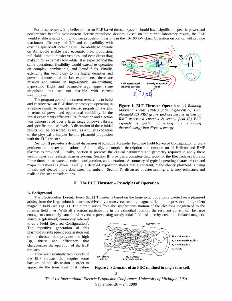
Figure 1. ELF Thruster Operation: (1) Rotating Magnetic Fields (RMF) form high-density, FRC plasmoid (2) FRC grows and accelerates driven by RMF generated currents & steady field (3) FRC expands as ejected, converting any remaining thermal energy into directed energy
The program goal of the current research is to build and characterize an ELF thruster prototype operating in a regime similar to current electric propulsion systems in terms of power and operational variability. In the initial experiments efficient FRC formation and ejection was demonstrated over a large range of power, thrust, and specific impulse levels. A discussion of these initial results will be presented, as well as a fuller exposition of the physical principles behind plasmoid propulsion with the ELF thruster.
.Section II provides a detailed discussion of Rotating Magnetic Field and Field Reversed Configuration physics pertinent to thruster applications. Additionally, a complete description and comparison of Helicon and RMF plasmas is provided. Finally, Section II presents the critical parameters and geometry required to apply these technologies in a realistic thruster system. Section III provides a complete description of the Electrodeless Lorentz Force thruster hardware, electrical configuration, and operation. A summary of typical operating characteristics and major milestones is given. Finally, a detailed exposition shows that a coherent, high-velocity plasmoid is being formed and ejected into a downstream chamber. Section IV discusses thruster scaling, efficiency estimates, and realistic thruster considerations.
II. The ELF Thruster – Principles of Operation
A. Background The Electrodeless Lorentz Force (ELF) Thruster is based on the large axial body force exerted on a plasmoid
arising from the large azimuthal currents driven by a transverse rotating magnetic field in the presence of a gradient magnetic field (see Fig. 1). The current arises from the synchronous motion of the electrons magnetized to the rotating field lines. With all electrons participating in the azimuthal rotation, the resultant current can be large enough to completely cancel and reverse a preexisting steady axial field and thereby create an isolated magnetic structure (plasmoid) commonly referred to as a Field Reversed Configuration1. The repetitive generation of this plasmoid its subsequent acceleration out of the thruster that provides the high Isp, thrust and efficiency that characterizes the operation of the ELF thruster.
3
EXTERNALFIELD
FRC CLOSED POLOIDAL FIELD
R – null radiusrs – separatrix radiusrc – coil radiusxs – rs/rc
EXTERNALFIELD
FRC CLOSED POLOIDAL FIELD
R – null radiusrs – separatrix radiusrc – coil radiusxs – rs/rc
Figure 2. Schematic of an FRC confined in single turn coil.
There are essentially two aspects of the ELF thruster that require some background and discussion in order to appreciate the transformational nature
The 31st International Electric Propulsion Conference, University of Michigan, USA September 20 – 24, 2009
of this new method of propulsion when compared to other electric propulsion devices. One concerns the generation mechanism and properties of the FRC plasmoid, and the second is the optimal deployment and wide application of the device to a number of unique space propulsion missions. The intent here is to address the first with a description of the FRC, the methods of formation, and in particular the novel method of generation employed in the ELF thruster.
A Field Reversed Configuration (FRC) plasmoid consists of a closed field line, fully ionized plasma confined by a large azimuthal self current (see Fig. 2). This plasma diamagnetic current flows opposite to the coil currents producing the external axial magnetic field. Typically FRC plasmoids are formed in a cylindrical coil with a fast (< 10 μs), and large (100’s kA) pulsed inductive discharge resulting in a stable, well-confined plasmoid that is neutral to translation. A simple conical coil can then be employed to produce the magnetic gradient desired for rapid ejection of the FRC for propulsion. The steeper the coil pitch (field gradient) and the shorter the length of the cone, the faster the more rapid will be the FRC acceleration and ejection. Typically this demands a very rapid and large flux change in order to generate a sufficiently large induced current. This method thus inherently requires a high voltage pulse power system for operation. As an aside it can be noted that the pulsed inductive thruster can be thought of in this way as the limit where the cone angle reaches 90°.
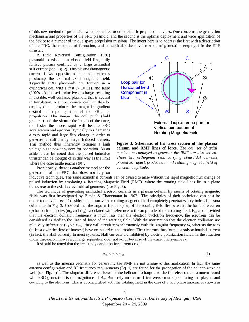
Propitiously, there is another method for the generation of the FRC that does not rely on inductive techniques. The same azimuthal currents can be caused to arise without the rapid magnetic flux change of pulsed induction by employing a Rotating Magnetic Field (RMF)2 where the rotating field lines lie in a plane transverse to the axis in a cylindrical geometry (see Fig. 3).
Jθ
⋅⋅
×
×
××Loop pair for Horizontal fieldComponent in blue
External loop antenna pair forvertical component of Rotating Magnetic Field
Jθ
⋅⋅
×
×
××Loop pair for Horizontal fieldComponent in blue
External loop antenna pair forvertical component of Rotating Magnetic Field
Figure 3. Schematic of the cross section of the plasma column and RMF lines of force. The coil set of axial conductors employed to generate the RMF are also shown. These two orthogonal sets, carrying sinusoidal currents phased 90° apart, produce an m=1 rotating magnetic field of constant amplitude.
The technique of generating azimuthal electron currents in a plasma column by means of rotating magnetic fields was first investigated by Blevin & Thonemann in 19623. The principles of their technique can best be understood as follows. Consider that a transverse rotating magnetic field completely penetrates a cylindrical plasma column as in Fig. 3. Provided that the angular frequency ω, of the rotating field lies between the ion and electron cyclotron frequencies (ωci and ωce) calculated with reference to the amplitude of the rotating field, Bω, and provided that the electron collision frequency is much less than the electron cyclotron frequency, the electrons can be considered as 'tied' to the lines of force of the rotating field. With the assumption that the electron collisions are relatively infrequent (νe << ωce), they will circulate synchronously with the angular frequency ω, whereas the ions (at least over the time of interest) have no net azimuthal motion. The electrons thus form a steady azimuthal current (in fact, the Hall current). In most systems, Hall currents are inhibited by electric polarization fields. In the situation under discussion, however, charge separation does not occur because of the azimuthal symmetry.
It should be noted that the frequency condition for current drive:
ωci < ω < ωce (1)
as well as the antenna geometry for generating the RMF are not unique to this application. In fact, the same antenna configuration and RF frequency requirements (Eq. 1) are found for the propagation of the helicon wave as well (see Fig. 4)4,5. The singular difference between the helicon discharge and the full electron entrainment found with FRC generation is the magnitude of Bω. Both rely on the m=1 transverse mode penetrating the plasma and coupling to the electrons. This is accomplished with the rotating field in the case of a two phase antenna as shown in
4The 31st International Electric Propulsion Conference, University of Michigan, USA
September 20 – 24, 2009
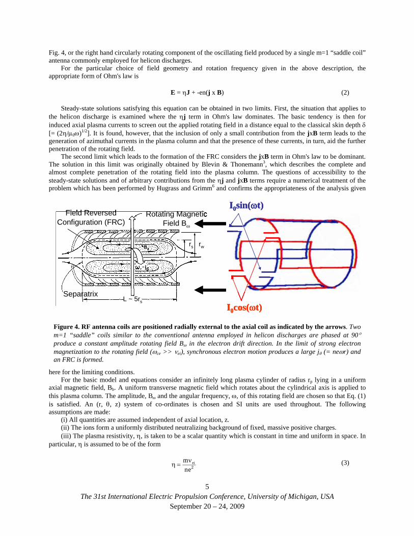
Fig. 4, or the right hand circularly rotating component of the oscillating field produced by a single m=1 “saddle coil” antenna commonly employed for helicon discharges.
For the particular choice of field geometry and rotation frequency given in the above description, the appropriate form of Ohm's law is
E = ηJ + -en(j x B) (2)
Steady-state solutions satisfying this equation can be obtained in two limits. First, the situation that applies to the helicon discharge is examined where the ηj term in Ohm's law dominates. The basic tendency is then for induced axial plasma currents to screen out the applied rotating field in a distance equal to the classical skin depth δ [= (2η/μ0ω)1/2]. It is found, however, that the inclusion of only a small contribution from the jxB term leads to the generation of azimuthal currents in the plasma column and that the presence of these currents, in turn, aid the further penetration of the rotating field.
The second limit which leads to the formation of the FRC considers the jxB term in Ohm's law to be dominant. The solution in this limit was originally obtained by Blevin & Thonemann3, which describes the complete and almost complete penetration of the rotating field into the plasma column. The questions of accessibility to the steady-state solutions and of arbitrary contributions from the ηj and jxB terms require a numerical treatment of the problem which has been performed by Hugrass and Grimm6 and confirms the appropriateness of the analysis given
here for the limiting conditions.
SeparatrixL ~ 5rs
Rotating MagneticField Bω
rs rw
Field ReversedConfiguration (FRC)
I0cos(ωt)
I0sin(ωt)
SeparatrixL ~ 5rs
Rotating MagneticField Bω
rs rw
Field ReversedConfiguration (FRC)
SeparatrixL ~ 5rs
Rotating MagneticField Bω
rs rw
Field ReversedConfiguration (FRC)
I0cos(ωt)
I0sin(ωt)
I0cos(ωt)
I0sin(ωt)
Figure 4. RF antenna coils are positioned radially external to the axial coil as indicated by the arrows. Two m=1 “saddle” coils similar to the conventional antenna employed in helicon discharges are phased at 90° produce a constant amplitude rotating field Bω in the electron drift direction. In the limit of strong electron magnetization to the rotating field (ωce >> νei), synchronous electron motion produces a large jθ (= neωr) and an FRC is formed.
For the basic model and equations consider an infinitely long plasma cylinder of radius rp lying in a uniform axial magnetic field, Bb. A uniform transverse magnetic field which rotates about the cylindrical axis is applied to this plasma column. The amplitude, Bω and the angular frequency, ω, of this rotating field are chosen so that Eq. (1) is satisfied. An (r, θ, z) system of co-ordinates is chosen and SI units are used throughout. The following assumptions are made:
(i) All quantities are assumed independent of axial location, z. (ii) The ions form a uniformly distributed neutralizing background of fixed, massive positive charges. (iii) The plasma resistivity, η, is taken to be a scalar quantity which is constant in time and uniform in space. In
particular, η is assumed to be of the form
2enm eiν
=η (3)
5The 31st International Electric Propulsion Conference, University of Michigan, USA
September 20 – 24, 2009
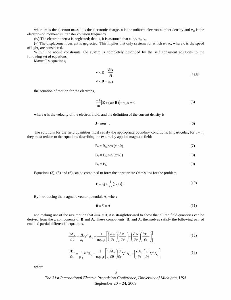
where m is the electron mass. e is the electronic charge, n is the uniform electron number density and νei is the electron-ion momentum transfer collision frequency.
(iv) The electron inertia is neglected; that is, it is assumed that ω << ωce,νei (v) The displacement current is neglected. This implies that only systems for which ωrp/c, where c is the speed
of light, are considered. Within the above constraints, the system is completely described by the self consistent solutions to the
following set of equations: Maxwell's equations,
jB
BE
0
tμ=×∇∂∂
=×∇ (4a,b)
the equation of motion for the electrons,
[ ] 0)(m
eei =ν−×+
− uBuE (5)
where u is the velocity of the electron fluid, and the definition of the current density is
J= neu . (6)
The solutions for the field quantities must satisfy the appropriate boundary conditions. In particular, for r ~ rp they must reduce to the equations describing the externally applied magnetic field:
Br = Bω cos (ωt-θ) (7)
Bθ = Bω sin (ωt-θ) (8)
Bz = Bb (9)
Equations (3), (5) and (6) can be combined to form the appropriate Ohm's law for the problem,
( BjjE ×+η=en
1 ) . (10)
By introducing the magnetic vector potential, A, where
AB ×∇= (11)
and making use of the assumption that ∂/∂z = 0, it is straightforward to show that all the field quantities can be derived from the z components of B and A. These components, Bz and Az themselves satisfy the following pair of coupled partial differential equations,
⎥⎦
⎤⎢⎣
⎡⎟⎟⎠
⎞⎜⎜⎝
⎛∂∂
⎟⎟⎠
⎞⎜⎜⎝
⎛θ∂
∂−⎟⎟⎠
⎞⎜⎜⎝
⎛θ∂
∂⎟⎟⎠
⎞⎜⎜⎝
⎛∂∂
μ+∇
μη
=∂∂
rBAB
rA
rne1A
tA zz
0z
2
0
z (12)
⎥⎦
⎤⎢⎣
⎡∇
θ∂∂
⎟⎟⎠
⎞⎜⎜⎝
⎛∂∂
−∇∂∂
⎟⎠⎞
⎜⎝⎛
θ∂∂
μ+∇
μη
=∂∂
z2z
z2z
0z
2
0
z Ar
AAr
Arne
1Bt
B (13)
where 6
The 31st International Electric Propulsion Conference, University of Michigan, USA September 20 – 24, 2009
2
2
22
r1
rr
rr1
θ∂∂
+⎟⎟⎠
⎞⎜⎜⎝
⎛∂∂
∂∂
=∇ .
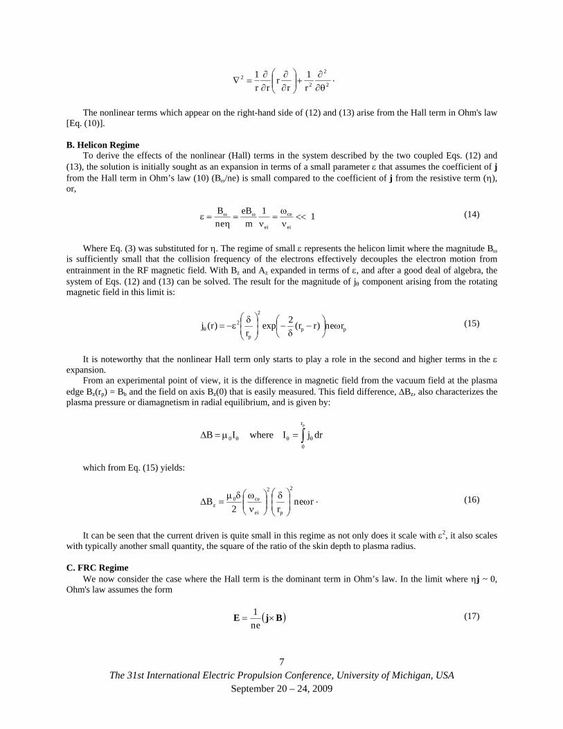
The nonlinear terms which appear on the right-hand side of (12) and (13) arise from the Hall term in Ohm's law [Eq. (10)].
B. Helicon Regime To derive the effects of the nonlinear (Hall) terms in the system described by the two coupled Eqs. (12) and
(13), the solution is initially sought as an expansion in terms of a small parameter ε that assumes the coefficient of j from the Hall term in Ohm’s law (10) (Bω/ne) is small compared to the coefficient of j from the resistive term (η), or,
11m
eBen
B
ei
ce
ei
<<νω
=ν
=η
=ε ωω (14)
Where Eq. (3) was substituted for η. The regime of small ε represents the helicon limit where the magnitude Bω is sufficiently small that the collision frequency of the electrons effectively decouples the electron motion from entrainment in the RF magnetic field. With Bz and Az expanded in terms of ε, and after a good deal of algebra, the system of Eqs. (12) and (13) can be solved. The result for the magnitude of jθ component arising from the rotating magnetic field in this limit is:
pp
2
p
2 ren)rr(2expr
)r(j ω⎟⎠⎞
⎜⎝⎛ −
δ−⎟
⎟⎠
⎞⎜⎜⎝
⎛ δε−=θ
(15)
It is noteworthy that the nonlinear Hall term only starts to play a role in the second and higher terms in the ε expansion.
From an experimental point of view, it is the difference in magnetic field from the vacuum field at the plasma edge Bz(rp) = Bb and the field on axis Bz(0) that is easily measured. This field difference, ΔBz, also characterizes the plasma pressure or diamagnetism in radial equilibrium, and is given by:
∫ θθθ =μ=Δpr
00 drjIwhereIB
which from Eq. (15) yields:
renr2
B2
p
2
ei
ce0z ω⎟
⎟⎠
⎞⎜⎜⎝
⎛ δ⎟⎟⎠
⎞⎜⎜⎝
⎛νωδμ
=Δ . (16)
It can be seen that the current driven is quite small in this regime as not only does it scale with ε2, it also scales with typically another small quantity, the square of the ratio of the skin depth to plasma radius.
C. FRC Regime We now consider the case where the Hall term is the dominant term in Ohm’s law. In the limit where ηj ~ 0,
Ohm's law assumes the form
( BjE ×=en
1 ) (17)
7The 31st International Electric Propulsion Conference, University of Michigan, USA
September 20 – 24, 2009
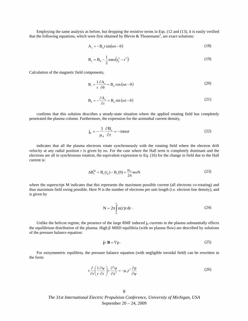
Employing the same analysis as before, but dropping the resistive terms in Eqs. (12 and (13), it is easily verified that the following equations, which were first obtained by Blevin & Thonemann3, are exact solutions:
( )θ−ω−= ω tsinrBAz (18)
( )22pbz rren
2BB −ω−=
1 . (19)
Calculation of the magnetic field components,
( θ−ω=θ∂
∂= ω tcosBA
r1B z
r ) (20)
( θ−ω=∂∂
−= ωθ tsinBr
AB z ) (21)
confirms that this solution describes a steady-state situation where the applied rotating field has completely penetrated the plasma column. Furthermore, the expression for the azimuthal current density,
renr
B1j z
0
ω−=∂∂
μ−=θ (22)
indicates that all the plasma electrons rotate synchronously with the rotating field where the electron drift velocity at any radial position r is given by rω. For the case where the Hall term is completely dominant and the electrons are all in synchronous rotation, the equivalent expression to Eq. (16) for the change in field due to the Hall current is:
Ne2
)0(B)r(BB 0zpz
Mz ω
πμ
=−=Δ (23)
where the superscript M indicates that this represents the maximum possible current (all electrons co-rotating) and thus maximum field swing possible. Here N is the number of electrons pre unit length (i.e. electron line density), and is given by
∫π=pr
0
drr)r(n2N . (24)
Unlike the helicon regime, the presence of the large RMF induced jθ currents in the plasma substantially effects the equilibrium distribution of the plasma. High β MHD equilibria (with no plasma flow) are described by solutions of the pressure balance equation:
p∇=×Bj . (25)
For axisymmetric equilibria, the pressure balance equation (with negligible toroidal field) can be rewritten in the form:
ψ∂∂
μ−=∂ψ∂
+⎟⎟⎠
⎞⎜⎜⎝
⎛∂ψ∂
∂∂ pr
zrr1
rr 2
02
2 (26)
8The 31st International Electric Propulsion Conference, University of Michigan, USA
September 20 – 24, 2009
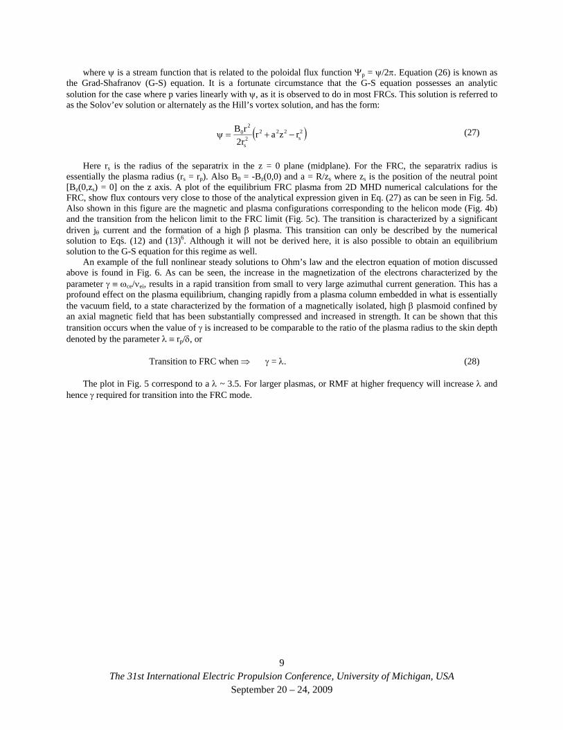
where ψ is a stream function that is related to the poloidal flux function Ψp = ψ/2π. Equation (26) is known as the Grad-Shafranov (G-S) equation. It is a fortunate circumstance that the G-S equation possesses an analytic solution for the case where p varies linearly with ψ, as it is observed to do in most FRCs. This solution is referred to as the Solov’ev solution or alternately as the Hill’s vortex solution, and has the form:
( 2s
2222s
20 rzarr2rB
−+=ψ ) (27)
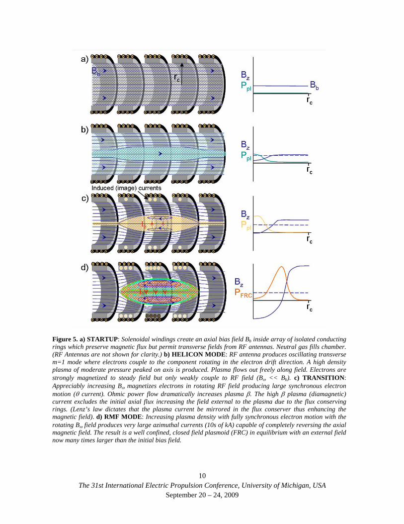
Here rs is the radius of the separatrix in the z = 0 plane (midplane). For the FRC, the separatrix radius is essentially the plasma radius (rs = rp). Also B0 = -Bz(0,0) and a = R/zs where zs is the position of the neutral point [Bz(0,zs) = 0] on the z axis. A plot of the equilibrium FRC plasma from 2D MHD numerical calculations for the FRC, show flux contours very close to those of the analytical expression given in Eq. (27) as can be seen in Fig. 5d. Also shown in this figure are the magnetic and plasma configurations corresponding to the helicon mode (Fig. 4b) and the transition from the helicon limit to the FRC limit (Fig. 5c). The transition is characterized by a significant driven jθ current and the formation of a high β plasma. This transition can only be described by the numerical solution to Eqs. (12) and (13)6. Although it will not be derived here, it is also possible to obtain an equilibrium solution to the G-S equation for this regime as well.
An example of the full nonlinear steady solutions to Ohm’s law and the electron equation of motion discussed above is found in Fig. 6. As can be seen, the increase in the magnetization of the electrons characterized by the parameter γ ≡ ωce/νei, results in a rapid transition from small to very large azimuthal current generation. This has a profound effect on the plasma equilibrium, changing rapidly from a plasma column embedded in what is essentially the vacuum field, to a state characterized by the formation of a magnetically isolated, high β plasmoid confined by an axial magnetic field that has been substantially compressed and increased in strength. It can be shown that this transition occurs when the value of γ is increased to be comparable to the ratio of the plasma radius to the skin depth denoted by the parameter λ ≡ rp/δ, or
Transition to FRC when ⇒ γ = λ. (28)
The plot in Fig. 5 correspond to a λ ~ 3.5. For larger plasmas, or RMF at higher frequency will increase λ and hence γ required for transition into the FRC mode.
9The 31st International Electric Propulsion Conference, University of Michigan, USA
September 20 – 24, 2009
The 31st International Electric Propulsion Conference, University of Michigan, USA
September 20 – 24, 2009
10
Figure 5. a) STARTUP: Solenoidal windings create an axial bias field Bb inside array of isolated conducting rings which preserve magnetic flux but permit transverse fields from RF antennas. Neutral gas fills chamber. (RF Antennas are not shown for clarity.) b) HELICON MODE: RF antenna produces oscillating transverse m=1 mode where electrons couple to the component rotating in the electron drift direction. A high density plasma of moderate pressure peaked on axis is produced. Plasma flows out freely along field. Electrons are strongly magnetized to steady field but only weakly couple to RF field (Bω << Bb). c) TRANSITION: Appreciably increasing Bω magnetizes electrons in rotating RF field producing large synchronous electron motion (θ current). Ohmic power flow dramatically increases plasma β. The high β plasma (diamagnetic) current excludes the initial axial flux increasing the field external to the plasma due to the flux conserving rings. (Lenz’s law dictates that the plasma current be mirrored in the flux conserver thus enhancing the magnetic field). d) RMF MODE: Increasing plasma density with fully synchronous electron motion with the rotating Bω field produces very large azimuthal currents (10s of kA) capable of completely reversing the axial magnetic field. The result is a well confined, closed field plasmoid (FRC) in equilibrium with an external field now many times larger than the initial bias field.
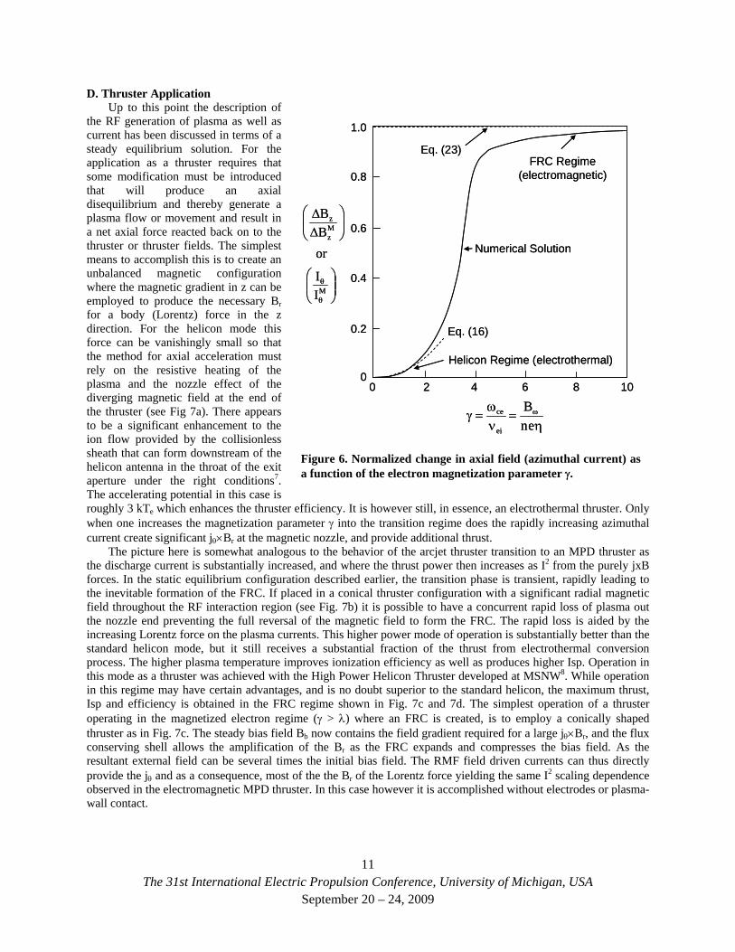
D. Thruster Application Up to this point the description of
the RF generation of plasma as well as current has been discussed in terms of a steady equilibrium solution. For the application as a thruster requires that some modification must be introduced that will produce an axial disequilibrium and thereby generate a plasma flow or movement and result in a net axial force reacted back on to the thruster or thruster fields. The simplest means to accomplish this is to create an unbalanced magnetic configuration where the magnetic gradient in z can be employed to produce the necessary Br for a body (Lorentz) force in the z direction. For the helicon mode this force can be vanishingly small so that the method for axial acceleration must rely on the resistive heating of the plasma and the nozzle effect of the diverging magnetic field at the end of the thruster (see Fig 7a). There appears to be a significant enhancement to the ion flow provided by the collisionless sheath that can form downstream of the helicon antenna in the throat of the exit aperture under the right conditions7. The accelerating potential in this case is roughly 3 kTe which enhances the thruster efficiency. It is however still, in essence, an electrothermal thruster. Only when one increases the magnetization parameter γ into the transition regime does the rapidly increasing azimuthal current create significant jθ×Br at the magnetic nozzle, and provide additional thrust.
0 2 4 6 8 10
1.0
0.8
0.6
0.4
0.2
0
⎟⎟⎠
⎞⎜⎜⎝
⎛
⎟⎟⎠
⎞⎜⎜⎝
⎛ΔΔ
θ
θM
Mz
z
II
orBB
Helicon Regime (electrothermal)
FRC Regime(electromagnetic)
η=
νω
=γ ω
enB
ei
ce
Eq. (16)
Eq. (23)
Numerical Solution
0 2 4 6 8 10
1.0
0.8
0.6
0.4
0.2
0
⎟⎟⎠
⎞⎜⎜⎝
⎛
⎟⎟⎠
⎞⎜⎜⎝
⎛ΔΔ
θ
θM
Mz
z
II
orBB
Helicon Regime (electrothermal)
FRC Regime(electromagnetic)
η=
νω
=γ ω
enB
ei
ce
Eq. (16)
Eq. (23)
Numerical Solution
Figure 6. Normalized change in axial field (azimuthal current) as a function of the electron magnetization parameter γ.
The picture here is somewhat analogous to the behavior of the arcjet thruster transition to an MPD thruster as the discharge current is substantially increased, and where the thrust power then increases as I2 from the purely jxB forces. In the static equilibrium configuration described earlier, the transition phase is transient, rapidly leading to the inevitable formation of the FRC. If placed in a conical thruster configuration with a significant radial magnetic field throughout the RF interaction region (see Fig. 7b) it is possible to have a concurrent rapid loss of plasma out the nozzle end preventing the full reversal of the magnetic field to form the FRC. The rapid loss is aided by the increasing Lorentz force on the plasma currents. This higher power mode of operation is substantially better than the standard helicon mode, but it still receives a substantial fraction of the thrust from electrothermal conversion process. The higher plasma temperature improves ionization efficiency as well as produces higher Isp. Operation in this mode as a thruster was achieved with the High Power Helicon Thruster developed at MSNW8. While operation in this regime may have certain advantages, and is no doubt superior to the standard helicon, the maximum thrust, Isp and efficiency is obtained in the FRC regime shown in Fig. 7c and 7d. The simplest operation of a thruster operating in the magnetized electron regime (γ > λ) where an FRC is created, is to employ a conically shaped thruster as in Fig. 7c. The steady bias field Bb now contains the field gradient required for a large jθ×Br, and the flux conserving shell allows the amplification of the Br as the FRC expands and compresses the bias field. As the resultant external field can be several times the initial bias field. The RMF field driven currents can thus directly provide the jθ and as a consequence, most of the the Br of the Lorentz force yielding the same I2 scaling dependence observed in the electromagnetic MPD thruster. In this case however it is accomplished without electrodes or plasma-wall contact.
11The 31st International Electric Propulsion Conference, University of Michigan, USA
September 20 – 24, 2009
zc
BrFjxB
zc
BrFjxB
zc
BrFjxB
zc
BrFjxB
Br(vac)
a)
b)
c)
d)
zc
BrFjxB
zc
BrFjxB
zc
BrFjxB
zc
BrFjxB
Br(vac)
zc
BrFjxB
zc
BrFjxB
zc
BrFjxB
zc
BrFjxB
zc
BrFjxB
zc
BrFjxB
zc
BrFjxB
zc
BrFjxB
zc
BrFjxB
zc
BrFjxB
zc
BrFjxB
zc
BrFjxB
Br(vac)
a)
b)
c)
d)
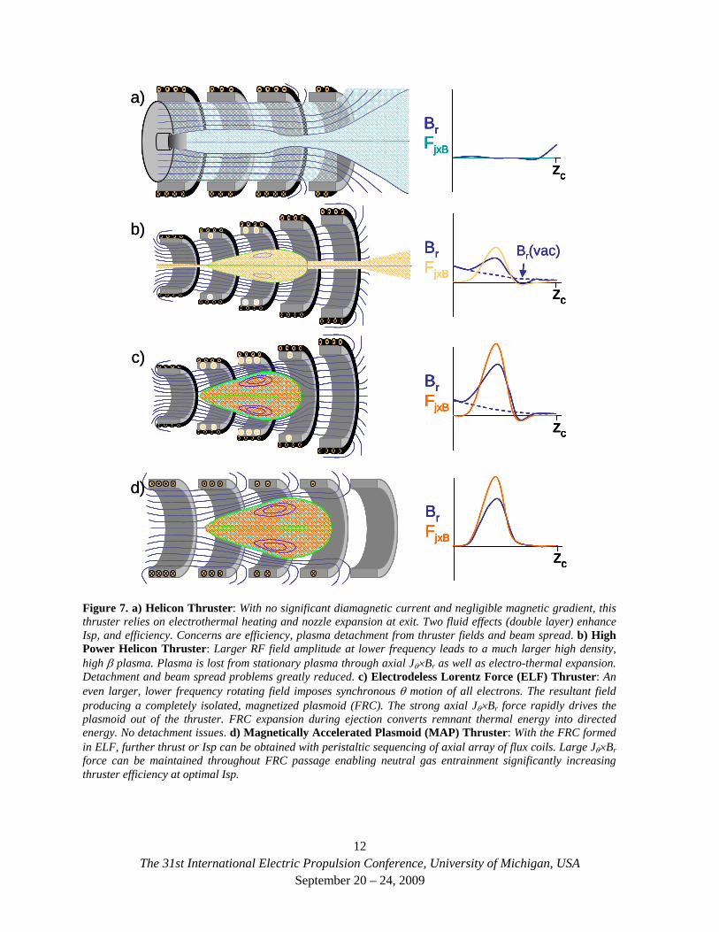
Figure 7. a) Helicon Thruster: With no significant diamagnetic current and negligible magnetic gradient, this thruster relies on electrothermal heating and nozzle expansion at exit. Two fluid effects (double layer) enhance Isp, and efficiency. Concerns are efficiency, plasma detachment from thruster fields and beam spread. b) High Power Helicon Thruster: Larger RF field amplitude at lower frequency leads to a much larger high density, high β plasma. Plasma is lost from stationary plasma through axial Jθ×Br as well as electro-thermal expansion. Detachment and beam spread problems greatly reduced. c) Electrodeless Lorentz Force (ELF) Thruster: An even larger, lower frequency rotating field imposes synchronous θ motion of all electrons. The resultant field producing a completely isolated, magnetized plasmoid (FRC). The strong axial Jθ×Br force rapidly drives the plasmoid out of the thruster. FRC expansion during ejection converts remnant thermal energy into directed energy. No detachment issues. d) Magnetically Accelerated Plasmoid (MAP) Thruster: With the FRC formed in ELF, further thrust or Isp can be obtained with peristaltic sequencing of axial array of flux coils. Large Jθ×Br force can be maintained throughout FRC passage enabling neutral gas entrainment significantly increasing thruster efficiency at optimal Isp.
12The 31st International Electric Propulsion Conference, University of Michigan, USA
September 20 – 24, 2009
There is an alternate method to the conical coil for generating the axial magnetic gradient field (i.e. Br) required for strong jθ ×Br thrust generation, and that is to produce it actively by sequencing an array of theta coils along the length of the thruster (see Fig. 7d) rather than maintain a fixed bias field with flux conserving rings. In this thruster, no bias field is required as the FRC is constantly being kept from the thruster wall by the activation of the coils as it passes resulting in the maximum possible magnetic force. Since the magnetic gradient is actively produced by the difference created by the sequential firing, it can be sustained undiminished throughout the length of the thruster. In the conical thruster the radial magnetic field pressure drops rapidly as the plasma expands and exits. Continually higher voltage operation of each coil is required if high Isp is desired. The results from the Magnetically Accelerated Plasmoid (MAP) thruster, which employed this technique, attest to this fact where Isp’s in the range of 18 to 22 ks were obtained9. The formation technique used in these experiments for the FRC was the field reversed technique so that high voltage was employed throughout.
With the ability form the FRC with the RMF technique, it would be possible to operate with this thruster geometry at much lower voltage. However a much more promising application would be to employ an array of such coils on the exit of the ELF thruster of Fig. 7c. With the Isp already in the optimal range (3-5 ks), increasing the Isp is probably not required. Instead neutral gas can be introduced into the FRC as it passes down the thruster body shown in Fig. 7d. With the charge exchange cross section much larger than the ionization cross section, the neutrals will be entrained with the electrons passing between neutrals and ions “herding” both along with the FRC. The FRC mass is thus increased but without the large ionization penalty. The effect of this additional mass would normally be a reduction in the velocity of the FRC as momentum is conserved. This is where the ability to continually push on the FRC with the plasmoid accelerator provides a way to maintain the FRC velocity while the mass is added. In this manner it is possible to significantly increase the thrust and efficiency of the thruster without resorting to high Isp. An ELF thruster has not yet been configured for neutral entrainment, but plans are currently underway to test this very promising enhancement.
E. Thruster Scaling and Energy Deposition The use of the RMF to generate the plasma and magnetic field currents radically changes both the manner in
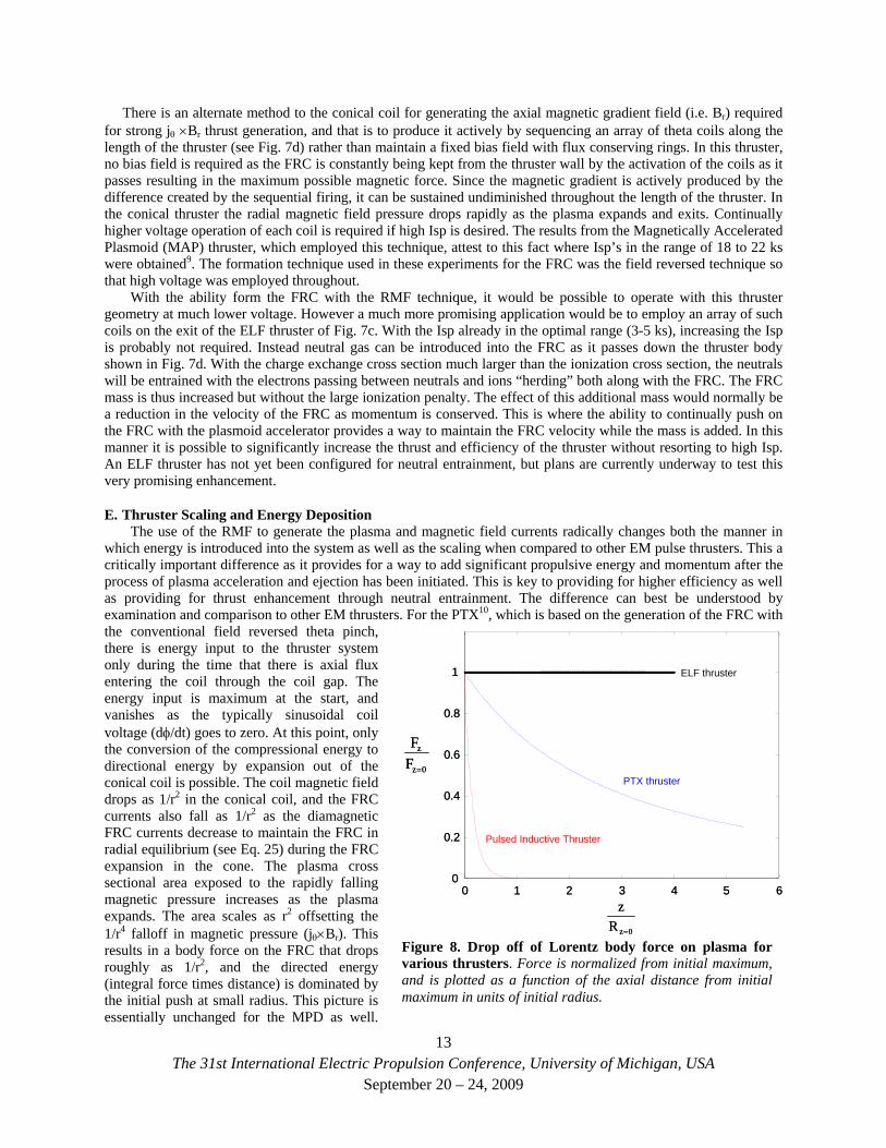
which energy is introduced into the system as well as the scaling when compared to other EM pulse thrusters. This a critically important difference as it provides for a way to add significant propulsive energy and momentum after the process of plasma acceleration and ejection has been initiated. This is key to providing for higher efficiency as well as providing for thrust enhancement through neutral entrainment. The difference can best be understood by examination and comparison to other EM thrusters. For the PTX10, which is based on the generation of the FRC with the conventional field reversed theta pinch, there is energy input to the thruster system only during the time that there is axial flux entering the coil through the coil gap. The energy input is maximum at the start, and vanishes as the typically sinusoidal coil voltage (dφ/dt) goes to zero. At this point, only the conversion of the compressional energy to directional energy by expansion out of the conical coil is possible. The coil magnetic field drops as 1/r2 in the conical coil, and the FRC currents also fall as 1/r2 as the diamagnetic FRC currents decrease to maintain the FRC in radial equilibrium (see Eq. 25) during the FRC expansion in the cone. The plasma cross sectional area exposed to the rapidly falling magnetic pressure increases as the plasma expands. The area scales as r2 offsetting the 1/r4 falloff in magnetic pressure (jθ×Br). This results in a body force on the FRC that drops roughly as 1/r2, and the directed energy (integral force times distance) is dominated by the initial push at small radius. This picture is essentially unchanged for the MPD as well.
0 1 2 3 4 5 60
0.2
0.4
0.6
0.8
1
0z
z
FF
=
0zRz
=
ELF thruster
PTX thruster
13
Pulsed Inductive Thruster
1
0 1 2 3 4 5 60
0.2
0.4
0.6
0.8
0z
z
FF
=
0zRz
=
ELF thruster
PTX thruster
Pulsed Inductive Thruster
Figure 8. Drop off of Lorentz body force on plasma for various thrusters. Force is normalized from initial maximum, and is plotted as a function of the axial distance from initial maximum in units of initial radius.
The 31st International Electric Propulsion Conference, University of Michigan, USA September 20 – 24, 2009
The body force is applied for only a short time as the plasma passes through the region of high jr and Bθ. The falloff in force as the plasma leaves the thruster is similar to the PTX FRC thruster. The Pulsed Inductive Thruster (PIT)11 is possibly the most extreme case of the force falloff as the plasma moves out away from the driver coils. In fact, it is usually modeled as falling exponentially in z (see Fig. 8).
The RMF generated FRC represents a significant change in the manner in which energy is introduced into the thruster. No longer is it necessary to have a high voltage power source or electrodes to introduce and apply the driving electric field to the plasma. The required electric field (see Eq. 17) can instead be introduced through the Hall Effect from the rotating transverse magnetic field produced by antenna coils external to the thruster. It is important to note that the ELF thruster is not a monolithic conducting structure as the MPD nozzle or conical theta pinch coil. Electrically, it is an axially segmented coil. The conductance in the azimuthal (θ) direction can be infinite, but the thruster must be constructed so that the axial currents are prohibited from flowing in response to the antenna currents (as in Fig. 4 for example). This break can take many forms from a few well isolated coils as in Fig. 7c, or a large stack of pancake coils with only the minimal insulation gap between them. Even a solenoidal winding is acceptable. These gaps provide for essentially the same capability as the flux gap in a theta pinch coil – a method for introducing energy into the thruster. The crucial difference here is that the energy enters through the action of a steady transverse rotating magnetic field and not from a pulsed coil. The other great advantage in this approach is there is no geometric limitation placed on the spatial variation of the RMF field. The magnitude can vary axially as needed along the thruster and does not have to fall off as 1/r2.
Possibly the most significant aspect for the RMF generation of the currents and fields that comprise the Lorentz force on the plasma is the fact that the magnitude of the RMF field and currents can be significantly smaller than the fields and plasma currents that are generated by the RMF. The Lorentz force scales with the product of the steady radial magnetic field and theta currents which, for the high β FRC, scale with Bext
2. With RMF current drive, the external field, Bext, after FRC generation to the RMF field, Bω, is typically 4 to 5 times larger. The energy required to generate the vacuum RMF can be a small fraction of the energy that flows into the thruster when the FRC is generated, and thus the RMF provides for a very efficient method to transfer translational energy to the FRC.
The scaling of the force for the RMF based FRC thruster can be obtained once the temporal and spatial extent of the RMF waveform is specified. For concreteness, the antenna employed for the initial ELF thruster will be assumed, that is, an antenna loop that is contoured to fit axially along the conical thruster wall. For this antenna then, Bω scales as 1/r reflecting the falloff inside the loop as one moves further away from the loop radial axis as the cone size increases. It should be noted that both Iθ and Bext scale with the plasma line density and RMF frequency (see Eq. 23), due to the fact that the electrons remain synchronously tied to the RMF field. The frequency is assumed a constant during RMF operation, and the line density, at least to first order, does not change as the FRC plasma expands. This means that both Iθ and Bext also remain constant as the FRC expands and moves down the thruster. Another way of viewing this is as follows. Even though the plasma density ne falls as 1/r2 as the FRC expands, the current density falls only as 1/r due to the increase in electron velocity with radius for synchronous motion at fixed ω, as expressed in Eq. (22). The total current integrated over r now scales as r as the FRC expands so that the total force remains constant. The applied forces for the various EM thrusters are given in Fig. 8. Since the RMF field amplitude can fall of due to plasma loading as well as the 1/r falloff as in the ELF thruster, it is important that the initial RMF amplitude be sufficient to drive the necessary currents at all locations and time, i.e. satisfy Eq. (28)
III. The ELF Thruster – Hardware Description
A. ELF Hardware The ELF thruster consists of a truncated conical quartz chamber/insulator 5mm in thickness, 420 mm long, large radius of 14 cm, and a cone angle of 8 degrees. into a resistive but conducting, stainless-steel chamber. The drift chamber is outfitted with external magnetic field diagnostics and a relatively slow axial magnetic field which provides for the control of the downstream acceleration and expansion of an ejected FRC. Additionally, the suitable magnetic nozzle and expansion regime can be created with simple electrical circuits. The entire assembly is shown in Fig. 10.
14The 31st International Electric Propulsion Conference, University of Michigan, USA
September 20 – 24, 2009
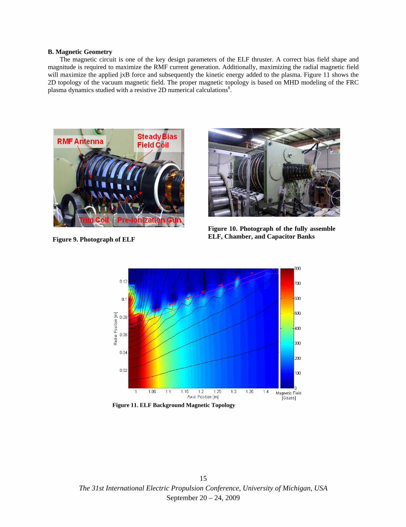
B. Magnetic Geometry The magnetic circuit is one of the key design parameters of the ELF thruster. A correct bias field shape and
magnitude is required to maximize the RMF current generation. Additionally, maximizing the radial magnetic field will maximize the applied jxB force and subsequently the kinetic energy added to the plasma. Figure 11 shows the 2D topology of the vacuum magnetic field. The proper magnetic topology is based on MHD modeling of the FRC plasma dynamics studied with a resistive 2D numerical calculations8.
Figure 10. Photograph of the fully assemble ELF, Chamber, and Capacitor Banks
Figure 9. Photograph of ELF
Figure 11. ELF Background Magnetic Topology
15The 31st International Electric Propulsion Conference, University of Michigan, USA
September 20 – 24, 2009
C. Circuit Design
Figure 12 Driver circuit with RMF antenna and tuning capacitor
0 0.05 0.1 0.15 0.20
0.5
1
1.5
2 x 10⁴
Time [ms]
Coi
l Vol
tage
[Vol
ts] Vacuum
Nitrogen
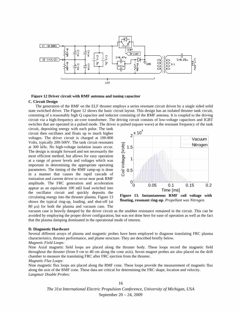
Figure 13. Instantaneous RMF coil voltage with floating, resonant ring-up. Propellant was Nitrogen.
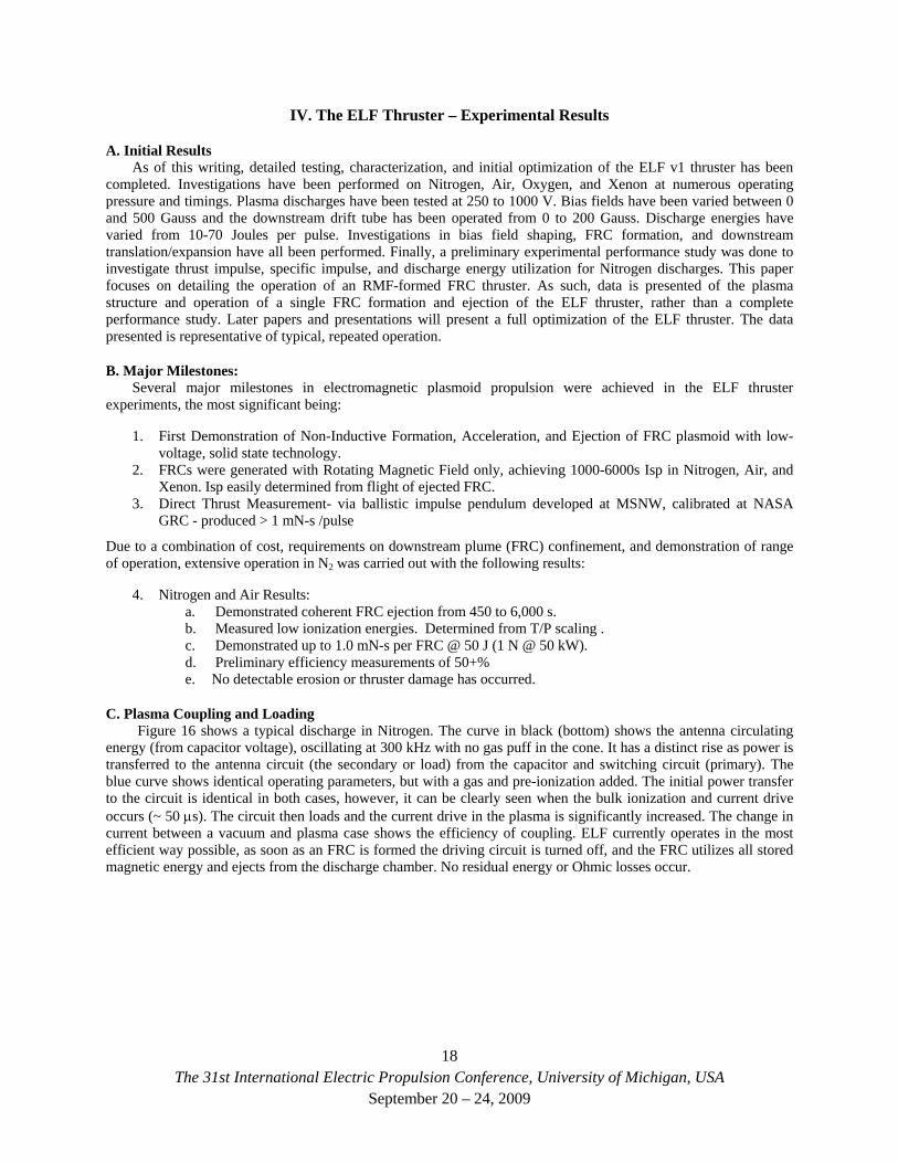
The generation of the RMF on the ELF thruster employs a series resonant circuit driven by a single sided solid state switched driver. The Figure 12 shows the basic circuit layout. This design has an isolated thruster tank circuit, consisting of a reasonably high Q capacitor and inductor consisting of the RMF antenna. It is coupled to the driving circuit via a high-frequency air-core transformer. The driving circuit consists of low-voltage capacitors and IGBT switches that are operated in a pulsed mode. The driver is pulsed (square wave) at the resonant frequency of the tank circuit, depositing energy with each pulse. The tank circuit then oscillates and floats up to much higher voltages. The driver circuit is charged at 100-800 Volts, typically 200-500V. The tank circuit resonates at 300 kHz. No high-voltage isolation issues occur. The design is straight forward and not necessarily the most efficient method, but allows for easy operation at a range of power levels and voltages which was important in determining the appropriate operating parameters. The timing of the RMF ramp-up is done in a manner that causes the rapid cascade of ionization and current driver to occur near peak RMF amplitude. The FRC generation and acceleration appear as an equivalent 100 mΩ load switched into the oscillator circuit and quickly deposits the circulating energy into the thruster plasma. Figure 13 shows the typical ring-up, loading, and shut-off (at 80 μs) for both the plasma and vacuum case. The vacuum case is heavily damped by the driver circuit as the snubber resistance remained in the circuit. This can be avoided by employing the proper driver configuration, but was not done here for ease of operation as well as the fact that the plasma damping dominated in the operational mode of interest. D. Diagnostic Hardware Several different arrays of plasma and magnetic probes have been employed to diagnose translating FRC plasma characteristics, thruster performance, and plume structure. They are described briefly below. Magnetic Field Loops: Nine Axial magnetic field loops are placed along the thruster body. These loops record the magnetic field throughout the thruster (from 0 cm to 40 cm along the cone axis). Seven magnet probes are also placed on the drift chamber to measure the translating FRC after FRC ejection from the thruster. Magnetic Flux Loops: Nine magnetic flux loops are placed along the RMF cone. These loops provide the measurement of magnetic flux along the axis of the RMF cone. These data are critical for determining the FRC shape, location and velocity. Langmuir Double Probes:
16The 31st International Electric Propulsion Conference, University of Michigan, USA
September 20 – 24, 2009
Internal double probes are utilized to collect downstream plasma density and velocity data. These probes are standard, asymmetric double probe. Probe current is collected with isolated, 30-Mhz bandwidth current transformers. The triple probe consists of a 1 m–long alumina rod with tungsten leads. Two such probes for a time-of-flight array described later. Additionally, radially integrated density and velocity yield a simple impulse measurement. Internal Magnetic Field Probe: An internal magnetic field probe is place in both the discharge cone and downstream to measure the field reversal of a translated FRC. It is swept radially for complete internal magnetic profiles of the FRC.
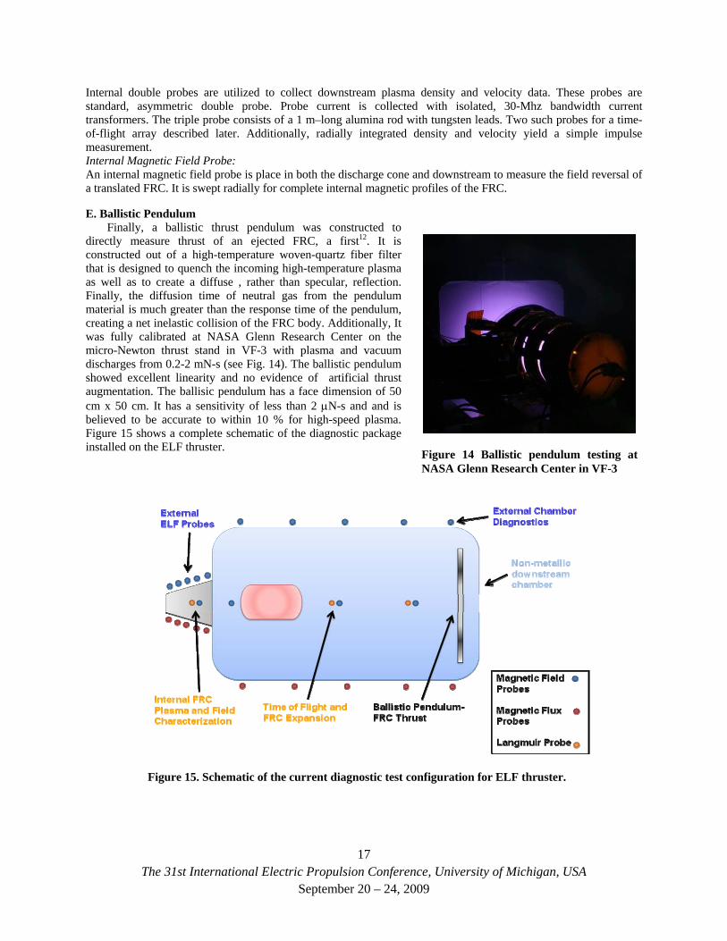
E. Ballistic Pendulum Finally, a ballistic thrust pendulum was constructed to
directly measure thrust of an ejected FRC, a first12. It is constructed out of a high-temperature woven-quartz fiber filter that is designed to quench the incoming high-temperature plasma as well as to create a diffuse , rather than specular, reflection. Finally, the diffusion time of neutral gas from the pendulum material is much greater than the response time of the pendulum, creating a net inelastic collision of the FRC body. Additionally, It was fully calibrated at NASA Glenn Research Center on the micro-Newton thrust stand in VF-3 with plasma and vacuum discharges from 0.2-2 mN-s (see Fig. 14). The ballistic pendulum showed excellent linearity and no evidence of artificial thrust augmentation. The ballisic pendulum has a face dimension of 50 cm x 50 cm. It has a sensitivity of less than 2 μN-s and and is believed to be accurate to within 10 % for high-speed plasma. Figure 15 shows a complete schematic of the diagnostic package installed on the ELF thruster.
Figure 14 Ballistic pendulum testing at NASA Glenn Research Center in VF-3
Figure 15. Schematic of the current diagnostic test configuration for ELF thruster.
17The 31st International Electric Propulsion Conference, University of Michigan, USA
September 20 – 24, 2009
IV. The ELF Thruster – Experimental Results
A. Initial Results As of this writing, detailed testing, characterization, and initial optimization of the ELF v1 thruster has been
completed. Investigations have been performed on Nitrogen, Air, Oxygen, and Xenon at numerous operating pressure and timings. Plasma discharges have been tested at 250 to 1000 V. Bias fields have been varied between 0 and 500 Gauss and the downstream drift tube has been operated from 0 to 200 Gauss. Discharge energies have varied from 10-70 Joules per pulse. Investigations in bias field shaping, FRC formation, and downstream translation/expansion have all been performed. Finally, a preliminary experimental performance study was done to investigate thrust impulse, specific impulse, and discharge energy utilization for Nitrogen discharges. This paper focuses on detailing the operation of an RMF-formed FRC thruster. As such, data is presented of the plasma structure and operation of a single FRC formation and ejection of the ELF thruster, rather than a complete performance study. Later papers and presentations will present a full optimization of the ELF thruster. The data presented is representative of typical, repeated operation.
B. Major Milestones: Several major milestones in electromagnetic plasmoid propulsion were achieved in the ELF thruster
experiments, the most significant being:
1. First Demonstration of Non-Inductive Formation, Acceleration, and Ejection of FRC plasmoid with low-voltage, solid state technology.
2. FRCs were generated with Rotating Magnetic Field only, achieving 1000-6000s Isp in Nitrogen, Air, and Xenon. Isp easily determined from flight of ejected FRC.
3. Direct Thrust Measurement- via ballistic impulse pendulum developed at MSNW, calibrated at NASA GRC - produced > 1 mN-s /pulse
Due to a combination of cost, requirements on downstream plume (FRC) confinement, and demonstration of range of operation, extensive operation in N2 was carried out with the following results:
4. Nitrogen and Air Results: a. Demonstrated coherent FRC ejection from 450 to 6,000 s. b. Measured low ionization energies. Determined from T/P scaling . c. Demonstrated up to 1.0 mN-s per FRC @ 50 J (1 N @ 50 kW). d. Preliminary efficiency measurements of 50+% e. No detectable erosion or thruster damage has occurred.
C. Plasma Coupling and Loading Figure 16 shows a typical discharge in Nitrogen. The curve in black (bottom) shows the antenna circulating
energy (from capacitor voltage), oscillating at 300 kHz with no gas puff in the cone. It has a distinct rise as power is transferred to the antenna circuit (the secondary or load) from the capacitor and switching circuit (primary). The blue curve shows identical operating parameters, but with a gas and pre-ionization added. The initial power transfer to the circuit is identical in both cases, however, it can be clearly seen when the bulk ionization and current drive occurs (~ 50 μs). The circuit then loads and the current drive in the plasma is significantly increased. The change in current between a vacuum and plasma case shows the efficiency of coupling. ELF currently operates in the most efficient way possible, as soon as an FRC is formed the driving circuit is turned off, and the FRC utilizes all stored magnetic energy and ejects from the discharge chamber. No residual energy or Ohmic losses occur.
18The 31st International Electric Propulsion Conference, University of Michigan, USA
September 20 – 24, 2009
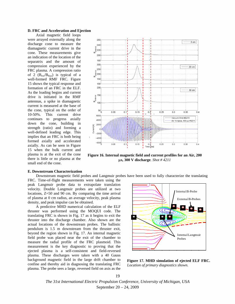
D. FRC and Acceleration and Ejection Axial magnetic field loops
were arrayed externally along the discharge cone to measure the diamagnetic current drive in the cone. These measurements give an indication of the location of the separatrix and the amount of compression experienced by the FRC plasma. A compression ratio of 2 (Bext/Bbias) is typical of a well-formed RMF FRC. Figure 15 shows the typical response and formation of an FRC in the ELF. As the loading begins and current drive is initiated in the RMF antennas, a spike in diamagnetic current is measured at the base of the cone, typical on the order of 10-50%. This current drive continues to progress axially down the cone, building in strength (ratio) and forming a well-defined leading edge. This implies that an FRC is both being formed axially and accelerated axially. As can be seen in Figure 15 when the bulk current and plasma is at the exit of the cone there is little or no plasma at the small end of the cone.
Figure 16. Internal magnetic field and current profiles for an Air, 200 μs, 300 V discharge. Shot # 4211
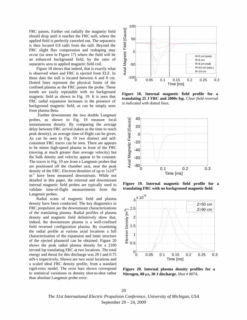
E. Downstream Characterization
External B-Probes
Internal B-Probe
Internal Langmuir Probes
Figure 17. MHD simulation of ejected ELF FRC. Location of primary diagnostics shown.
Downstream magnetic field probes and Langmuir probes have been used to fully characterize the translating FRC. Time-of-flight measurements were taken using the peak Langmuir probe data to extrapolate translation velocity. Double Langmuir probes are utilized at two locations, Z=50 and 90 cm. By comparing the time arrival of plasma at 0 cm radius, an average velocity, peak plasma density, and peak impulse can be obtained.
A predictive MHD numerical calculation of the ELF thruster was performed using the MOQUI code. The translating FRC is shown in Fig. 17 as it begins to exit the thruster into the discharge chamber. Also shown are the actual locations of the downstream probes. The ballistic pendulum is 1.5 m downstream from the thruster exit, beyond the region shown in Fig. 17. An internal magnetic field probe was placed near the exit of the chamber to measure the radial profile of the FRC plasmoid. This measurement is the key diagnostic to proving that the ejected plasma is a self-consistent and field-reversed plasma. These discharges were taken with a 40 Gauss background magnetic field in the large drift chamber to confine and thereby aid in diagnosing the translating FRC plasma. The probe sees a large, reversed field on axis as the
19The 31st International Electric Propulsion Conference, University of Michigan, USA
September 20 – 24, 2009
0 0.05 0.1 0.15 0.2 0.25 0.3-100
-50
0
50
100
Time [ms]
Axi
al M
agne
tic F
ield
[Gau
ss]
R=0 cm (axis)R=4 cmR=8 cm (null)R=10 cm (sep.)R=14 cm
Figure 18. Internal magnetic field profile for a translating 25 J FRC and 2000s Isp. Clear field reversal is indicated with dotted lines.
FRC passes. Farther out radially the magnetic field should drop until it reaches the FRC null, where the applied field is perfectly canceled out. The separatrix is then located 0.8 radii from the null. Beyond the FRC slight flux compression and reshaping may occur (as seen in Figure 17) where the field will be an enhanced background field, by the ratio of separatrix area to applied magnetic field coil.
Figure 18 shows that indeed, that is exactly what is observed when and FRC is ejected from ELF. In these data the null is located between 6 and 8 cm. Dotted lines represent the physical limits of the confined plasma as the FRC passes the probe. These trends are easily repeatable with no background magnetic field as shown in Fig. 19. It is seen that FRC radial expansion increases in the presence of background magnetic field, as can be simply seen from plasma Beta.
20
0 0.05 0.1 0.15 0.2 0.25 0.30
0.5
1
1.5
2
2.5
3 x 10¹⁸
Time [ms]
Ele
ctro
n D
ensi
ty [m
-3]
Z=50 cmZ=90 cm
Figure 20. Internal plasma density profiles for a Nitrogen, 80 μs, 30 J discharge. Shot # 8074.
Farther downstream the two double Langmuir probes, as shown in Fig. 19 measure local instantaneous density. By comparing the average delay between FRC arrival (taken as the time to reach peak density), an average time-of-flight can be given. As can be seen in Fig. 19 two distinct and self-consistent FRC traces can be seen. There are appears to be minor high-speed plasma in front of the FRC (moving at much greater than average velocity) but the bulk density and velocity appear to be constant. The traces in Fig. 19 are from a Langmuir probes that are positioned off the chamber axis, near the peak density of the FRC. Electron densities of up to 1x10¹⁹ m-3 have been measured downstream. While not detailed in this paper, the external and downstream internal magnetic field probes are typically used to validate time-of-flight measurements from the Langmuir probes.
0 0.1 0.2 0.3-80
-60
-40
-20
0
20
40
Time [ms]
Axi
al M
agne
tic F
ield
[Gau
ss]
Figure 19. Internal magnetic field profile for a translating FRC with no background magnetic field.
Radial scans of magnetic field and plasma density have been conducted. The key diagnostics in FRC propulsion are the downstream characterizations of the translating plasma. Radial profiles of plasma density and magnetic field definitively show that, indeed, the downstream plasma is a well-confined field reversed configuration plasma. By examining the radial profile at various axial locations a full characterization of the expansion and inner structure of the ejected plasmoid can be obtained. Figure 20 shows the peak radial plasma density for a 2100 second Isp translating FRC at two locations. The total energy and thrust for this discharge was 28 J and 0.75 mN-s trspectively. Shown are two axial locations and a scaled ideal FRC density profile, from a standard rigid-rotor model. The error bars shown correspond to statistical variations in density shot-to-shot rather than absolute Langmuir probe error.
The 31st International Electric Propulsion Conference, University of Michigan, USA September 20 – 24, 2009
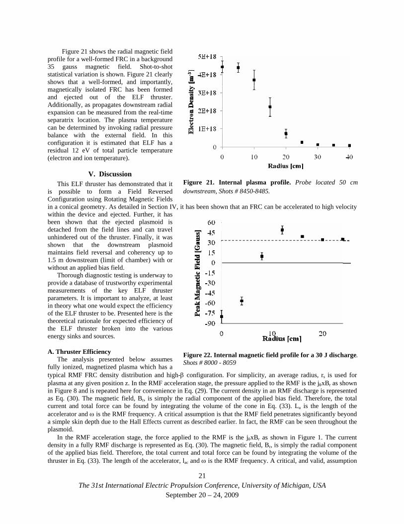
Figure 21 shows the radial magnetic field profile for a well-formed FRC in a background 35 gauss magnetic field. Shot-to-shot statistical variation is shown. Figure 21 clearly shows that a well-formed, and importantly, magnetically isolated FRC has been formed and ejected out of the ELF thruster. Additionally, as propagates downstream radial expansion can be measured from the real-time separatrix location. The plasma temperature can be determined by invoking radial pressure balance with the external field. In this configuration it is estimated that ELF has a residual 12 eV of total particle temperature (electron and ion temperature).
Figure 21. Internal plasma profile. Probe located 50 cm downstream, Shots # 8450-8485.
V. Discussion
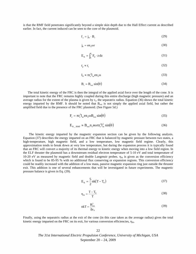
Figure 22. Internal magnetic field profile for a 30 J discharge. Shots # 8000 - 8059
This ELF thruster has demonstrated that it is possible to form a Field Reversed Configuration using Rotating Magnetic Fields in a conical geometry. As detailed in Section IV, it has been shown that an FRC can be accelerated to high velocity within the device and ejected. Further, it has been shown that the ejected plasmoid is detached from the field lines and can travel unhindered out of the thruster. Finally, it was shown that the downstream plasmoid maintains field reversal and coherency up to 1.5 m downstream (limit of chamber) with or without an applied bias field.
Thorough diagnostic testing is underway to provide a database of trustworthy experimental measurements of the key ELF thruster parameters. It is important to analyze, at least in theory what one would expect the efficiency of the ELF thruster to be. Presented here is the theoretical rationale for expected efficiency of the ELF thruster broken into the various energy sinks and sources.
A. Thruster Efficiency The analysis presented below assumes
fully ionized, magnetized plasma which has a typical RMF FRC density distribution and high-β configuration. For simplicity, an average radius, rs is used for plasma at any given position z. In the RMF acceleration stage, the pressure applied to the RMF is the jθxBr as shown in Figure 8 and is repeated here for convenience in Eq. (29). The current density in an RMF discharge is represented as Eq. (30). The magnetic field, Br, is simply the radial component of the applied bias field. Therefore, the total current and total force can be found by integrating the volume of the cone in Eq. (33). La is the length of the accelerator and ω is the RMF frequency. A critical assumption is that the RMF field penetrates significantly beyond a simple skin depth due to the Hall Effects current as described earlier. In fact, the RMF can be seen throughout the plasmoid.
In the RMF acceleration stage, the force applied to the RMF is the jθxBr as shown in Figure 1. The current density in a fully RMF discharge is represented as Eq. (30). The magnetic field, Br, is simply the radial component of the applied bias field. Therefore, the total current and total force can be found by integrating the volume of the thruster in Eq. (33). The length of the accelerator, lac and ω is the RMF frequency. A critical, and valid, assumption
21The 31st International Electric Propulsion Conference, University of Michigan, USA
September 20 – 24, 2009
is that the RMF field penetrates significantly beyond a simple skin depth due to the Hall Effect current as described earlier. In fact, the current induced can be seen to the core of the plasmoid.
rz Bjf ⋅= θ (29)
renj eω=θ (30)
(31) ∫ ⋅=0 ZK dzzFE al
rr ≈
ωπ≈ 3 enlrI
(32) sp
(33) θ eacs
( ) = θsinBB extr (34)
The total kinetic energy of the FRC is then the integral of the applied axial force over the length of the cone. It is important to note that the FRC remains highly coupled during this entire discharge (high magnetic pressure) and an average radius for the extent of the plasma is given by rs, the separatrix radius. Equation (36) shows the total kinetic energy imparted by the RMF. It should be noted that Bext is not simply the applied axial field, but rather the amplified field due to the presence of the FRC plasmoid. (See Figure 5d.)
( )θωπ= sinBenlrF exteac3sz (35)
( )θωπ≈ 23 sinlrenBE acseextRMF_K (36)
The kinetic energy imparted by the magnetic expansion section can be given by the following analysis. Equation (37) describes the energy imparted on an FRC that is balanced by magnetic pressure between two states, a high-temperature, high magnetic field, and a low temperature, low magnetic field regime. Clearly, this approximation tends to break down at very low temperature, but during the expansion process it is typically found that an FRC will convert a majority of its thermal energy to kinetic energy when moving into a low field region. In the ELF thruster the plasmoid has a downstream residual electron temperature of 5-10 eV and total temperature of 10-20 eV as measured by magnetic field and double Langmuir probes. ηth is given as the conversion efficiency which is found to be 85-95 % with no additional flux conserving or expansion regions. This conversion efficiency could be readily increased with the addition of a low mass, passive magnetic expansion ring just outside the thruster exit. This addition is one of several enhancements that will be investigated in future experiments. The magnetic pressure balance is given in Eq. (39).
( 0K TTnk25E −= ) (37)
T
0th
TT −=η (38)
0
ext
2BnkTμ
=2
(39)
Finally, using the separatrix radius at the exit of the cone (in this case taken as the average radius) gives the total kinetic energy imparted on the FRC on its exit, for various conversion efficiencies, ηth.
22The 31st International Electric Propulsion Conference, University of Michigan, USA
September 20 – 24, 2009
⎟⎟⎠
⎞⎜⎜⎝
⎛π
μη≈ ac
2s
0
2ext
thTh_K lr2BE (40)
FRC based propulsion utilizes high density plasma that is formed and ejected in ~ 20 μsec. Complete ionization happens in less than 1 μs. This rapid, high-collision-rate ionization process is exceedingly efficient and minimizes wall collision, recombination, and radiation loss mechanisms. This is of interest because ionization is a major loss mechanism in traditional electric propulsion devices, and is particularly dominant at low specific impulses (particle kinetic energy) in Hall Effect and ion thrusters. This ionization loss energy is the full energy required to get a neutral particle to the exit of the thruster and includes radiation, excitation, recombination, electron bombardment ionization, and wall energy losses. A basic analysis of plasma ionization, excitation, and charge-exchange collisions for a given plasma temperature and density show that increasing density and/or temperature drastically decreases excitation and ionization losses 8,13. Additionally, pulsed plasmas even further reduce radiation losses due to the time required for excitation. It has been demonstrated that ionization energies approaching the theoretical minima can be achieved in a pulsed inductive source of this type. For the temperature and densities of the ELF thruster the expected ionization potential and excitation energies are 20-40 eV/ion, dependent on propellant and operating condition. Finally, the magnetic confinement of an ELF thruster drastically reduces wall collisions. Therefore, given a per-ion ionization and excitation loss of 40 eV/ion, ionization losses are simply:
]eV/J[e*]eV[40*MmE
0
bition = (41)
Mbit is the total propellant mass in the FRC and M0 is the atomic mass of the propellant. Ohmic coil losses are taken to be the resistive losses in the magnetic coils (RCoil), capacitors, transmission lines and antenna (Rcircuit) over the discharge length. Bias capacitor bank and pre-ionization circuit are simply the energy utilized in the bias and pre-ionization discharge circuits during the discharge.
( ) 2RMSCircuitCoil IRRESRE ++τΔ=Ω (42)
The thruster efficiency ηELF can now be evaluated:
Ω+++
η+=η
EEEEEE
ionthRMF_K
ththRMF_KELF
(43)
where Eth is the total thermal energy input into the FRC. Using representative numbers from a Xenon, 50 J ELF discharge, with a separatrix radius ~ 0.8r and measured density and mass bits the following table can be compiled. It can be clearly seen that for these operating conditions an RMF FRC system can be highly efficient as shown in Table 1.
Energy Terms for 50 J total input Contribution Kinetic - RMF Acceleration – EK_RMF 40 Kinetic – Thermal Expansion – EK_th 8 Thermal – Unrecovered (1-ηth) Eth <1 Ionization, Excitation, and Wall Losses -Eion 2 Ohmic – Antenna and Capacitor resistance 2 Ohmic – Bias coil and flux coil resistance <1 Ohmic – discharge initiator (PI) <1 Total Thruster Efficiency (from Eq.43) 85+%
Table 1. ELF Energy Distribution
In conclusion, the ELF thruster has been operated at MSNW LLC and has demonstrated the successful RMF formation, acceleration, and ejection of an FRC. Presented has been a detailed discussion of background physics and operating principles of the ELF thruster. Additionally discussed are the initial experimental results showing the successful operation of the ELF thruster and a full characterization of resulting, translated plasmoids. Hopefully this document will serve as a fundamental primer for RMF-formed FRC propulsion systems.
23The 31st International Electric Propulsion Conference, University of Michigan, USA
September 20 – 24, 2009
The 31st International Electric Propulsion Conference, University of Michigan, USA
September 20 – 24, 2009
24
Acknowledgments This work was funded under an STTR grant sponsored by the Air Force Office of Scientific Research. The
authors would particularly like to thank Dr. Mitat Birkan and Dr. Jean Luc Cambier for support of the ELF thruster program.
References 1M. Tuszewski, “Field Reversed Configurations”, Nuclear Fusion Vol. 28, 2033 (1988) 2I.R. Jones, “A review of rotating magnetic current drive …”, Phys. of Plasmas, 6, 1950 (1999) 3H.A. Blevin and P.C. Thonemann, “Plasma Confinement using an Alternating Magnetic Field”, Nucl. Fus. Suppl. Part I, 55
(1962). 4Francis F. Chen, “Physics of helicon discharges”, Phys. Plasmas 3, 1783 (1996). 5Yasuyoshi Yasaka and Yoshiaki Hara, “Role of Helicon Waves on High-Density Plasma Production”, Jpn. J. Appl. Phys., 33
5950 (1994). 6W.N. Hugrass and R.C. Grimm, “A numerical study of the generation of an azimuthal current in a plasma cylinder using a
transverse rotating magnetic field”, J. Plasma Physics, 26 455 (1981). 7Christine Charles and Rod Boswell, “Current-free double-layer formation in a high-density helicon discharge”, Appl. Phys.
Lett., 82, 1356 (2003). 8John Slough, Robert Winglee, and Timothy Ziemba, “Performance Enhancement and Modeling of the High Power Helicon
Plasma Thruster”, AIAA2006-5257, 42nd AIAA/ASME/SAE/ASEE Joint Propulsion Conference and Exhibit, Sacramento, CA, 9 - 12 July 2006.
9John Slough, Arthur Blair, Chris Pihl, and George Votroubek, “Magnetically Accelerated Plasmoid (MAP) Thruster – Initial Results and Future Plans”, IEPC-2007-16, The 30th International Electric Propulsion Conference, Florence, Italy, September 17-20, 2007
10Adam Martin, R. E., Michael Lee. “The Plasmoid Thruster Experiment (PTX)”. 2004 APS Division of Plasma Physics Meeting November 19, 2004.
11Daily, C.L. and Lovberg, R.H. “The PIT MkV Pulsed Inductive Thruster”. NASA Contractor Report 19115. 12John Slough, David Kirtley, and Thom “Quartz Fiber Ballistic Thrust Stand for Pulsed Plasma Impulse Measurements”.
Review of Scientific Instruments (Pending) 2009. 13Lieberman, M. and A. Lichtenberg. Principles of plasma discharges and materials processing, Wiley, 2005.