m-508 - artila four dual color leds indicate the data traffic at the serial ports. when rxd line is...
TRANSCRIPT

M-508Linux ARM9 System on Module
User GuideVersion 1.0
Copyright © Artila Electronics Co., Ltd. All Rights Reserved.

Table of Contents
1. Introduction ................................................................................................................ 1
1.1 Features .............................................................................................................................. 1
1.2 Packing List ......................................................................................................................... 1
1.3 Optional Accessory ............................................................................................................. 1
2. Layout ......................................................................................................................... 2
3. Pin Assignment and Definition .................................................................................. 3
3.1 Power LED (PWR) .............................................................................................................. 3
3.2 Ready LED (RDY) ............................................................................................................... 3
3.3 LAN1 / Act (LAN)................................................................................................................. 3
3.4 Serial Port LED (LD3 ~ LD6) .............................................................................................. 3
3.5 Debug LED (LD1 ~ 2) ......................................................................................................... 3
3.6 Serial Port Pin Definition (DB9 Male) .................................................................................. 4
3.7 Serial Console Port ............................................................................................................. 4
3.8 Power Connector ................................................................................................................ 5
3.9 Ethernet Port ....................................................................................................................... 5
3.10 SD Socket ........................................................................................................................... 5
3.11 USB Port ............................................................................................................................. 5
3.12 Reset Button ....................................................................................................................... 5
3.13 General Purpose IO (GPIO) ................................................................................................ 6
3.14 CN1 JTAG Header .............................................................................................................. 6
3.15 COM2 TTL Header ............................................................................................................. 6
3.16 JP2 Boot Manager Selection .............................................................................................. 7
3.17 USB Client Connector (J3) .................................................................................................. 7
3.18 RS-485 Terminator Jumper (J5, J7, J8, J9) ........................................................................ 7
3.19 USB Host Connector (J2) ................................................................................................... 7
3.20 Factory Default Settings ...................................................................................................... 7
3.21 Network Settings ................................................................................................................. 8
3.22 Wireless LAN Configuration ................................................................................................ 8
3.23 File System ......................................................................................................................... 9
3.24 Devices list .......................................................................................................................... 9
3.25 Utility Software .................................................................................................................. 10
4. Artila Utility Software ................................................................................................11
4.1 update ............................................................................................................................... 11
4.2 setuart ............................................................................................................................... 11
4.3 gpioctl ................................................................................................................................ 11
4.4 How to Make More Utility Software ................................................................................... 12
4.5 Mounting External Storage Memory ................................................................................. 12
4.6 Welcome Message ........................................................................................................... 12
4.7 Web Page Directory .......................................................................................................... 12
4.8 Adjust the System Time .................................................................................................... 13
4.9 SSH Console ..................................................................................................................... 13
4.10 Install GNU Toolchain ....................................................................................................... 13
4.11 Getting Started with the Hello Program ............................................................................ 14
4.12 Enable Serial Console Port ............................................................................................... 14
5. Frequently Asked Question ......................................................................................16
5.1 Forgot Password ............................................................................................................... 16
5.2 Reset M-508 to Factory Default Setting ............................................................................ 16
5.3 Forgot the IP Address ....................................................................................................... 16
M-508 User Guide
‧1‧
1. Introduction M-508 is a Linux ready Single Board Computer featuring four serial ports, 10/100Mbps Ethernet, USB
port and SD socket for flash disk expansion. The pre-install Linux OS and GNU tool chain make
M-508 ready for your application development.
1.1 Features ARM920T ARM Thumb Processor with 200MIPS at 180MHz, Memory Management Unit
16-KByte Data Cache and 16-KByte Instruction Cache
64MB SDRAM, 32MB Flash on board
512KB non-volatile FRAM (M-508T only)
One 10/100Mbps Ethernet
Two USB 2.0 full speed (12Mbps) Host Ports
Multimedia Card Interface for SD memory card
Four RS-232/485 ports software selectable
Port 4 also supports RS-422
32 General Purpose DIO
+5VDC power input
Pre-installed Standard Linux 2.6.14 OS
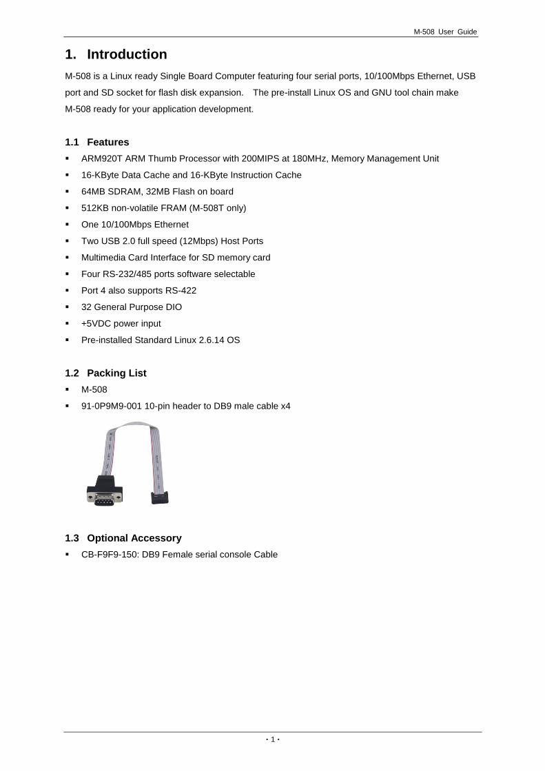
1.2 Packing List M-508
91-0P9M9-001 10-pin header to DB9 male cable x4
1.3 Optional Accessory CB-F9F9-150: DB9 Female serial console Cable
M-508 User Guide
‧2‧
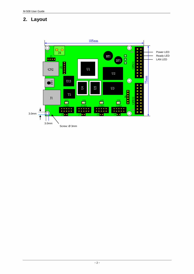
2. Layout
JTAG CN1
3.0mm
3.0mm Screw: Ø 3mm
Power LED Ready LED LAN LED

M-508 User Guide
‧3‧
3. Pin Assignment and Definition 3.1 Power LED (PWR) Power LED will keep solid green when power is applied.
3.2 Ready LED (RDY) After Power ON, M-508 will decompress the kernel and root file system to RAMDISK. Once system is
boot up, the Ready LED will show solid green. The Ready LED will be turned off after M-508 received
“halt” command.
3.3 LAN1 / Act (LAN) When Ethernet port are connected to the network, Link/Act will show solid green and if there is traffic in
the Ethernet, this LED will flash.
3.4 Serial Port LED (LD3 ~ LD6) These four dual color LEDs indicate the data traffic at the serial ports. When RXD line is high then
Orange light is ON and when TXD line is high, Green light is ON.
3.5 Debug LED (LD1 ~ 2) The debug LEDs are located near LAN LED and are used for system boot debug. If system are
correctly boot, they are switch off.
Serial Ports (COM1/COM2/COM3/COM4)
Pin No. RS-232 RS-485 RS-422**
1 DCD* - Tx-
2 DSR* - -
3 Rx - Tx+
4 RTS - -
5 Tx Data+ Rx+
6 CTS - -
7 DTR* Data- Rx-
8 - - -
9 GND GND GND
10 - - -
Note: * Port 2 only ** Port 4 only

M-508 User Guide
‧4‧
3.6 Serial Port Pin Definition (DB9 Male) The serial port pin assignment is shown as follow:
Port 1, 3: RS-232 / 485 (software selection)
RS-232: RXD, TXD, RTS, CTS, GND
RS-485: Data+, Data-, GND
Port 2: RS-232 / 485 (software selection)
RS-232: RXD, TXD, RTS, CTS, DSR, DTR, DCD, GND
RS-485: Data+, Data-, GND
Port 4: RS-232 / 422 / 485 (software selection)
RS-232: RXD, TXD, RTS, CTS, GND
RS-422: TXD+, TXD-, RXD+, RXD-, GND
RS-485: Data+, Data-, GND
Pin No. RS-232 RS-422 RS-485
1 DCD* TXD- -
2 RXD TXD+ -
3 TXD RXD+ DATA+
4 DTR* RXD- DATA-
5 GND GND GND
6 DSR* - -
7 RTS - -
8 CTS - -
9 - - -
3.7 Serial Console Port Serial console port is used to access M-508 using RS-232. At factory, serial console port is disabled
because serial console port shares the COM3 serial port connector with the pin definition as shown:
Pin No. RS-232
1 -
2 -
3 -
4 -
5 GND
6 -
7 TXD
8 RXD
9 -
User need to prepare or order a serial console cable (CB-F9F9-100) and enable the serial console port
Port 1~4
Note: * Port 2 only
Port 3
Baud Rate: 115200 Data bits: 8 Parity: N Stop bit: 1 Terminal type: ANSI

M-508 User Guide
‧5‧
as described in Enable Serial Console port section.
3.8 Power Connector Connect the +5VDC power line to M-508. If the power is properly supply, the power LED
will show a solid green color.
Note
Please check the power voltage and polarity before connecting it.
3.9 Ethernet Port Pin No. Signal
1 ETx+
2 ETx-
3 ERx+
6 ERx-
The Ethernet Port uses RJ45 connector.
3.10 SD Socket The SD socket is compatible with SD memory card specification version 1.0. The SD Socket is
located in the back panel of the PCB.
3.11 USB Port The USB port is a USB2.0 high speed host port. It can be used to expand the hardware function of
M-508 and exchange file and data between PC. Currently the hardware support by M-508 USB is
shown as follow:
USB Storage Device
USB to Wireless LAN Adaptor (Ralink RT2571)
USB to Modem (CDC compliant)
USB Camera
Contact Artila if you find your hardware is not shown on the list.
3.12 Reset Button Press the “Reset” button to activate the hardware reset. Please always use “reboot” command to
reset M-508. You should only use this function if the software reboot does not function properly.
M-508 User Guide
‧6‧
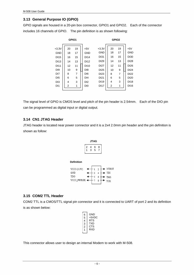
3.13 General Purpose IO (GPIO) GPIO signals are housed in a 20-pin box connector, GPIO1 and GPIO2. Each of the connector
includes 16 channels of GPIO. The pin definition is as shown following:
The signal level of GPIO is CMOS level and pitch of the pin header is 2.54mm. Each of the DIO pin
can be programmed as digital input or digital output.
3.14 CN1 JTAG HeaderJTAG header is located near power connector and it is a 2x4 2.0mm pin header and the pin definition is
shown as follow:
3.15 COM2 TTL HeaderCOM2 TTL is a CMOS/TTL signal pin connector and it is connected to UART of port 2 and its definition
is as shown below:
This connector allows user to design an internal Modem to work with M-508.
+-
12345678910
11121314151617181920
DI0DI2DI4DI6DI8DI10DI12DI14GND+5V
DI1DI3DI5DI7DI9DI11DI13DI15GND
+3.3V
12345678910
1112
1314151617181920
DI16DI18DI20DI22DI24DI26
DI28DI30GND+5V
DI17DI19DI21DI23DI25DI27
DI29DI31GND
+3.3V
GPIO1 GPIO2
2 4 6 81 3 5 7
JTAG
Definition
654321
GND+5VDCRTSTXDCTSRXD

M-508 User Guide
‧7‧
3.16 JP2 Boot Manager Selection JP2 is boot selection jumper near CN1. Set to position 2-3 always. Change the setting will cause
incorrectly boot up.
3.17 USB Client Connector (J3)USB client port is reserved for future enhancement. This function is disabled by software.
Pin definition is as follow:
1. Data +
2. Data -
3. Host_detect
4. GND
3.18 RS-485 Terminator Jumper (J5, J7, J8, J9) Short the jumper will enable the 120ohm terminator as shown below:
3.19 USB Host Connector (J2)USB host connector is designed for internal USB device connection. The connector is a six pins wafer
box with lock 1.0mm wire to board connector and its pin definition is as shown below:
wafer box with lock 1.0 mm
3.20 Factory Default Settings
LAN 1 IP Address: 192.168.2.127
Login: guest
Password: guest
Supervisor: root (use ssh to login)
Password: root
Serial Console: Disabled
3 2 1
1 2 3 4
123456
+5VDCHDMAHDPAGNDN/CGND
M-508 User Guide
‧8‧
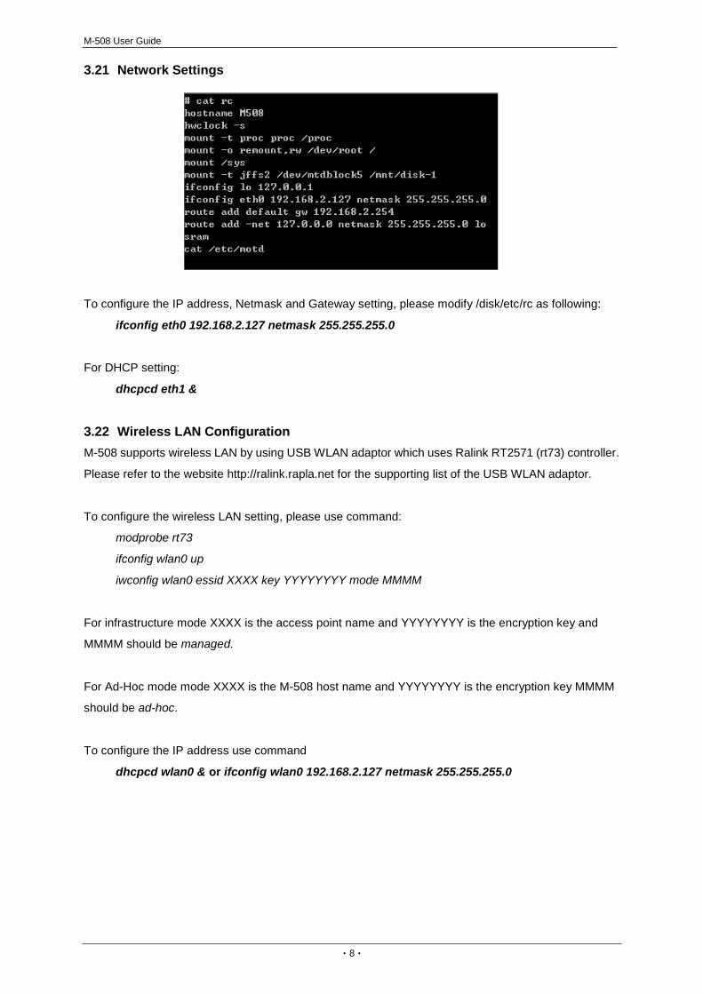
3.21 Network Settings
To configure the IP address, Netmask and Gateway setting, please modify /disk/etc/rc as following:
ifconfig eth0 192.168.2.127 netmask 255.255.255.0
For DHCP setting:
dhcpcd eth1 &
3.22 Wireless LAN Configuration M-508 supports wireless LAN by using USB WLAN adaptor which uses Ralink RT2571 (rt73) controller.
Please refer to the website http://ralink.rapla.net for the supporting list of the USB WLAN adaptor.
To configure the wireless LAN setting, please use command:
modprobe rt73
ifconfig wlan0 up
iwconfig wlan0 essid XXXX key YYYYYYYY mode MMMM
For infrastructure mode XXXX is the access point name and YYYYYYYY is the encryption key and
MMMM should be managed.
For Ad-Hoc mode mode XXXX is the M-508 host name and YYYYYYYY is the encryption key MMMM
should be ad-hoc.
To configure the IP address use command
dhcpcd wlan0 & or ifconfig wlan0 192.168.2.127 netmask 255.255.255.0
M-508 User Guide
‧9‧
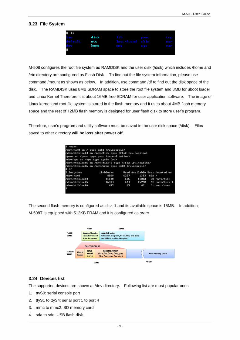
3.23 File System
M-508 configures the root file system as RAMDISK and the user disk (/disk) which includes /home and
/etc directory are configured as Flash Disk. To find out the file system information, please use
command /mount as shown as below. In addition, use command /df to find out the disk space of the
disk. The RAMDISK uses 8MB SDRAM space to store the root file system and 8MB for uboot loader
and Linux Kernel Therefore it is about 16MB free SDRAM for user application software. The image of
Linux kernel and root file system is stored in the flash memory and it uses about 4MB flash memory
space and the rest of 12MB flash memory is designed for user flash disk to store user’s program.
Therefore, user’s program and utility software must be saved in the user disk space (/disk). Files
saved to other directory will be loss after power off.
The second flash memory is configured as disk-1 and its available space is 15MB. In addition,
M-508T is equipped with 512KB FRAM and it is configured as sram.
3.24 Devices listThe supported devices are shown at /dev directory. Following list are most popular ones:
1. ttyS0: serial console port
2. ttyS1 to ttyS4: serial port 1 to port 4
3. mmc to mmc2: SD memory card
4. sda to sde: USB flash disk

M-508 User Guide
‧10‧
5. ttyUSB0 to ttyUSB1: USB RS-232 adaptor (fdti_sio.ko)
6. rtc: Real Time Clock
7. gpio: General Purpose digital I/O
8. ttyACM0 and ttyACM1: USB Modem (CDC compliant)
3.25 Utility Software M-508 includes busybox utility collection and Artila utility software as follow:
M-508 User Guide
‧11‧
4. Artila Utility Software The introduction of Artila utility software as follow:
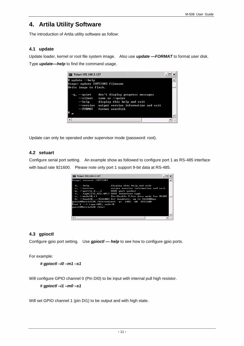
4.1 update Update loader, kernel or root file system image. Also use update —FORMAT to format user disk.
Type update—help to find the command usage.
Update can only be operated under supervisor mode (password: root).
4.2 setuart Configure serial port setting. An example show as followed to configure port 1 as RS-485 interface
with baud rate 921600. Please note only port 1 support 9-bit data at RS-485.
4.3 gpioctl Configure gpio port setting. Use gpioctl — help to see how to configure gpio ports.
For example:
# gpioctl –i0 –m1 –s1
Will configure GPIO channel 0 (Pin DI0) to be input with internal pull high resistor.
# gpioctl –i1 –m0 –s1
Will set GPIO channel 1 (pin DI1) to be output and with high state.

M-508 User Guide
‧12‧
4.4 How to Make More Utility Software You might also find utility software available on Artila FTP under /Matrix and iPAC/utility such as
ntpclient, ssh, scp, bluez and ssh-keygen. If you want, you can ftp or copy the utility software to
M-508 user disk (/disk). Also you can use find the source code and use the GNU Toolchain to make
the utility by yourself.
4.5 Mounting External Storage Memory To find out the device name of the external memory device which plug into M-508, you can use the
command
/dmesg | grep sd
or
/dmesg | grep mmc
Type
mount /dev/sda1 to mount the USB disk and
mount /dev/mmc0 to mount SD card
4.6 Welcome Message To modify the welcome message, user can use text edit to modify the /etc/motd.
4.7 Web Page Directory The web pages are placed at /home/httpd and the boa.conf contains the boa web server settings. The
home page name should be index.html.

M-508 User Guide
‧13‧
4.8 Adjust the System Time To adjust the RTC time, you can follow the command:
/date MMDDhhmmYYYY
where
MM=Month (01~12)
DD=Date (01~31)
hh=Hour
mm=minutes
YYYY= Year
/hwclock –w
To write the date information to RTC.
User can also use NTP client utility on Artila FTP to adjust the RTC time.
/ntpclient [time server ip]
4.9 SSH Console M-508 support SSH. If you use Linux computer, you can use SSH command to login M-508. The
configuration of SSH and key are located at /etc/config/ssh
The key generation program is available on Artila FTP: /matrix and ipac /utility/ssh_keygen
User can copy this program to M-508 to generate the key.
4.10 Install GNU Toolchain Find a PC with Linux 2.6.X Kernel installed and login as a root user then copy the
arm-linux-3.3.2.tar.gz to root directory of PC. Under root directory, type following command to install
the M-508 Gnu Toolchain.
#tar zxvf arm-linux-3.3.2.tar.gz

M-508 User Guide
‧14‧
4.11 Getting Started with the Hello Program There are many example programs on Artila FTP. To compile the sample you can use the Make file to
and type:
make
To compile and link the library. Once done, use ftp command
ftp 192.168.2.127
And bin command to set transfer mode to binary
ftp>bin
To transfer the execution file to M-508 user disk (/disk) and use
chmod +x file.o
To change it to execution mode and
./file.o
to run the file.
4.12 Enable Serial Console Port The serial console port is disabled as factory default setting. To enable the serial console, you need
to use the serial console cable (91-RJCON-100) and connect it to port 3. Use any terminal software
such as hyper terminal and setting as follow:
Baud Rate: 115200
Data bits: 8
Parity: N
Stop bit: 1
Terminal type: ANSI

M-508 User Guide
‧15‧
Right after powering on the system, keep typing $ continuously until you see the message as shown in
the figure followed. Console (ttyS0) stands for console port ttyS0 is enabled. Repeat this procedure
will disable the serial console and screen will show “Console (null)”.
M-508 User Guide
‧16‧
5. Frequently Asked Question 5.1 Forgot Password If you forgot the password for login, please use serial console to modify the password.
5.2 Reset M-508 to Factory Default Setting The factory default setting is available at /default directory. User can copy the default setting to /etc
and /home directories manually or format the user disk to set M-508 to factory default setting.
Performing disk format will erase all the files in user disk. Therefore please backup the files you need
in USBDISK first before format the disk. Use command:
#update —FORMAT
To format disk.
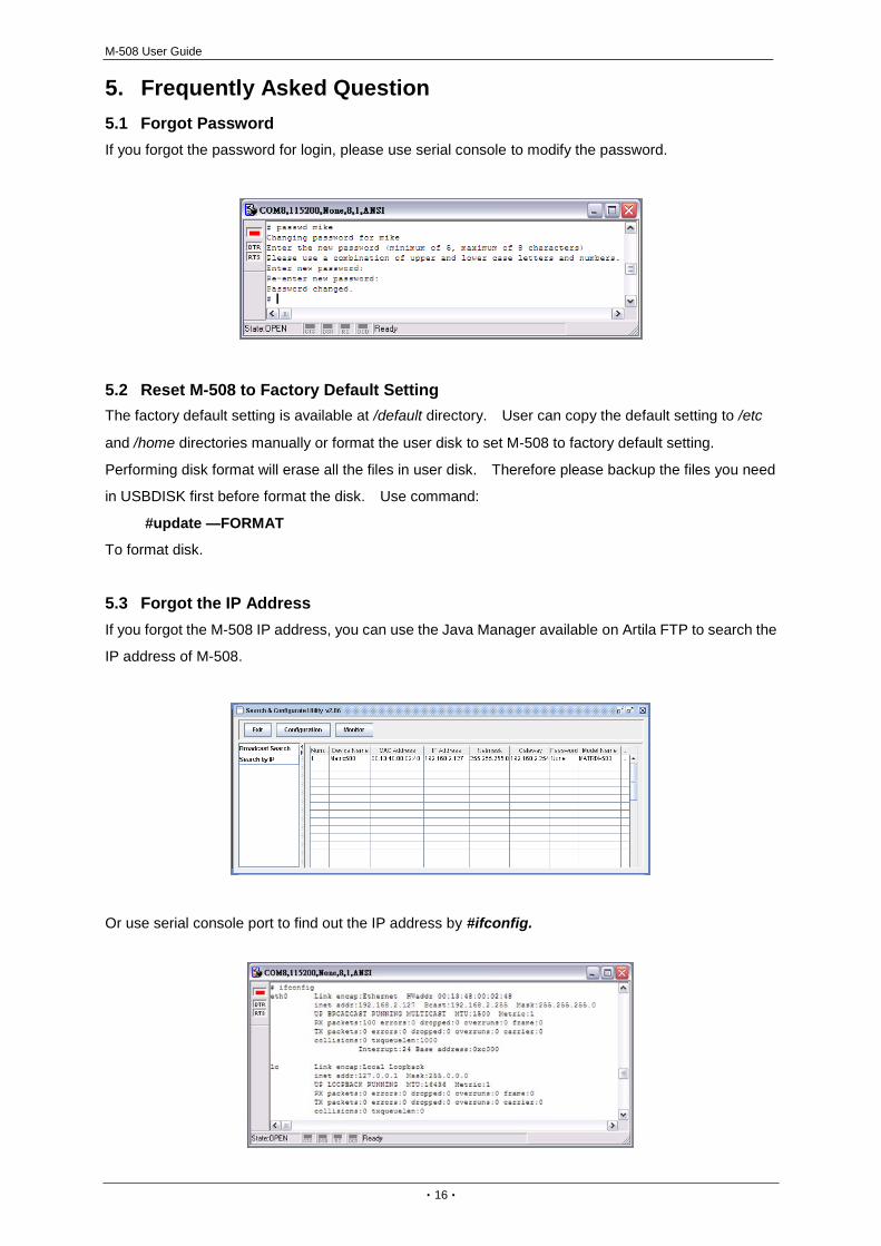
5.3 Forgot the IP Address If you forgot the M-508 IP address, you can use the Java Manager available on Artila FTP to search the
IP address of M-508.
Or use serial console port to find out the IP address by #ifconfig.