istruzioni per l'uso i instructions for use … possible interference, data transmission is...
TRANSCRIPT

I
GB
D
F
E
NL
ISTRUZIONI PER L'USO
INSTRUCTIONS FOR USE
BEDIENUNGSANLEITUNG
NOTICE D'UTILISATION
INSTRUCCIONES PARA EL USO
GEBRUIKSAANWIJZING

ENG
LISH
GB
20
Thank you for choosing the Super Crono
Wireless.
The Super Crono Wireless is a completely wire-
less home trainer. All the information is transmit-
ted via radio by the transmission unit to the
computer on a frequency of 433MHz. In order to
avoid possible interference, data transmission is
coded so that only the correct information, rele-
vant to training, is displayed on the computer
(even in the presence of interference on the same
frequency). The coding also enables the simulta-
neous training of several cyclists training with the
Super Crono Wireless.
IMPORTANT
• Do not stop the rotation of the bicycle
wheel by using caliper or disk brake. This
seriously damages the roller and the tire.
• If the training data is not correctly displa-
yed during the first use, the resistance unit
must be synchronised with the computer
(see the section “Synchronisation”).
INTRODUCTION
Check the presence of all the following compo-
nents.
1 Wireless Fluid unit with two AA batteries (Ref. A)
1 stand (Ref.B)
1 left bushing pin (Ref.C)
1 ring (Ref.D)
1 right bushing pin (Ref.E)
1 fixing lever (Ref.F)
1 unit support upper base (Ref.G)
1 unit support lower base (Ref.H)
1 screw M6 x45 mm (Ref.I)
1 washer Ø6 mm (Ref.L)
1 nut M6 (Ref.M)
1 bag of unit accessories:
1 hex wrench
2 screws M6 x 55 mm (Ref.N)
2 washers Ø6 mm (Ref.O)
1 Quick release (Ref.P)
1 Travel Block (Ref.Q)
1 receiver (Ref.R)
1 console with two AA batteries (Ref.S)
GBEN
GLISH
21
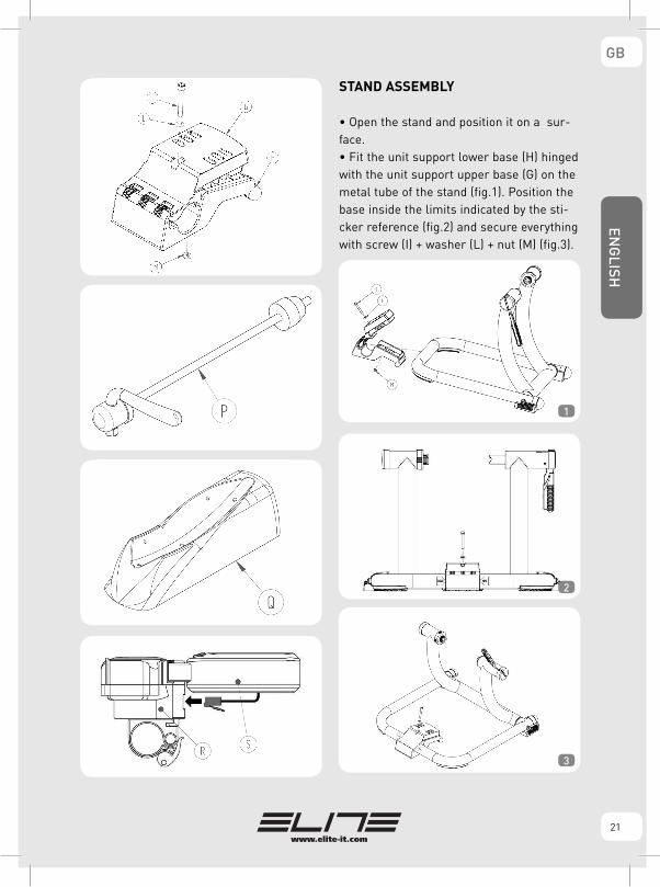
STAND ASSEMBLY
• Open the stand and position it on a sur-face.• Fit the unit support lower base (H) hinged with the unit support upper base (G) on the metal tube of the stand (fig.1). Position the base inside the limits indicated by the sti-cker reference (fig.2) and secure everything with screw (I) + washer (L) + nut (M) (fig.3).
1
2
3

22
ENG
LISH
GB
TRANSMITTER BATTERIES ASSEMBLY
1 Remove the resistance unit from its package
and place it turned upside down on a table or a
plain surface.
2 Remove the cover placed under the resistance
unit by unscrewing the two screws. Insert the two
AA type batteries taking care to note the polarity
indicated on the cover and on the sticker applied
on the rear side of the resistance unit.
3 Replace the cover and fasten it with the two self
– tapping screws Ø 3.5 (fig. 4).
UNIT INSTALLATION
• Fix the resistance unit on the base (G,H) with screws (N) + washers (O) (fig.5).
• On the base (G) the are three pairs of holes; use the various holes according to the diameter of the bicycle wheel: for 29” wheels, pair of rear holes (fig.6); for 28” wheels, pair of middle holes (fig.7); for 26” wheels, pair of front holes (fig.8).
4
6
7
8
5

23
ENG
LISHGB
• Tighten down the screws (N) (fig.9).
FITTING THE BICYCLE• Make sure the quick release of the bicycle rear wheel is properly fixed.• Turn the lever (F) to the “open” position (fig.10).
• Release the ring (D) by unscrewing it (fig.11).
• Put the bicycle in position, inserting the left end of the rear quick release in the left bushing (C)
(fig.12). For safer clamping of the bicycle on the stand, make sure the lever of the quick release is horizontal (fig.13).
• Close the lever (F), making sure it starts pres-sing the quick release inside the predefined workarea; between 30° and 45° (fig. 14 and fig.15).
9
10
13
12
11
14
15

24
ENG
LISH
GB
• If the lever (F) starts pressing the quick release in the advanced work position (fig.16), screw theleft bushing pin (C) (fig.17) so that the lever starts working inside the predefined work area (between30° and 45°).
• If the lever (F) starts pressing the quick release in the delayed work position (fig.18), unscrew theleft bushing pin (C) (fig.19) so that the lever starts working inside the predefined work area (between30° and 45°).
• After establishing the correct position of the left bushing pin (C), hold the left bushing pin with one hand (C) and with the other, tighten the ring (D) (fig.20) thus clamping everything.
• Close the lever (F) in the “close” position, pushing it only with the palm of the hand (fig.21 and 22) and taking care not to put fingers between the lever and frame (fig.23).
16
17
18
19
20
21

25
ENG
LISHGB
• Make sure the lever of the quick release is inside the grooves of the left bushing pin (C) (fig.24).
• If the wheel is too far away with respect to the middle of the roller (fig.25), shift the resistan-ce unit (A) by loosening the unit fixing screws (N) and secure them in the more correct position (fig.26 and 27).
22
23
24
25
26
27
26
ENG
LISH
GB
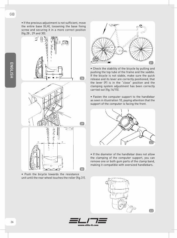
• If the previous adjustment is not sufficient, move the entire base (G,H), loosening the base fixing screw and securing it in a more correct position (fig.28 , 29 and 30).
• Push the bicycle towards the resistance unit until the rear wheel touches the roller (fig.31).
• Check the stability of the bicycle by pulling and pushing the top tube of the frame and the saddle. If the bicycle is not stable, make sure the quick release and its lever are correctly positioned, that the lever (F) is in the “close” position and the clamping system adjustment has been correctly carried out (fig.14/15).
• Fasten the computer support to the handlebar as seen in illustration 10, paying attention that the support of the computer is facing the front.
• If the diameter of the handlebar does not allow the clamping of the computer support, you can remove one or both gum parts of the clamp band, making it compatible with oversized handlebars.
28
31
29
30
32
33

27
ENG
LISHGB
COMPUTER INSTALLATION• Open the battery housing under the display and place the two AA type batteries that are in the computer box. Observe the polarity indicated on the batteries housing.• Attach the computer to the support, as seen in(fig. 34).
• Connect the cable, that is on the rear side of the computer, to its correspondent connection loca-ted on the support (fig. 35).
• Make sure that the computer is securely fixed to the handlebar and that its position allows a clear view of the display when pedaling. • Now it is possible to begin training and to check all the training data on the display.
COMPUTER USE
SWITCHING ON
• If not already done, insert the batteries in the computer. • For computers provided with a switch, turn the switch to "ON".• For computers without switch, press one of the two buttons.
SETTINGS
To use the Super Crono Wireless correctly it is needed to first set the parameters. To do this you must enter the SET UP screen. To enter the SET UP screen keep the right button (MODE) pressed for at least three seconds. The SET UP message will appear. When the button is released, the computer shows the first screen of the SET UP phase.Attention: it is possible to enter the SET UP
phase only at zero speed. During this operation
we suggest to detach the cable M on the rear side
of the computer.
The first step is to choose the unit of measure-ment between the metric and imperial systems.To do this it is needed to push the left button (SET). On the screen METER (Meters), KM/H (Kilometers per hour) and KILO (Kgs) or FOOT (Foot), M/H (Miles per hour) and LB (Pounds / ounces) will appear alternatively. By pressing the MODE button the units chosen are confirmed and you pass on to the next screen.
In the upper part of this screen there is a three digit number that indicates rider weight plus the bike weight, shown in the previously chosen measurement unit. The weight set by the manufacturer or the last data inserted will appear. To modify this data, push the SET button to modify the digit that is flashing and the MODE button to confirm the chosen value and pass on to the next digit that will start flashing/blinking. Repeat the operation to set all three digits of the weight. Push the MODE button to confirm the
34
35
Screen for the setting of the athlete’s weight.
Screen that shows the choice of the measures unit.

28
ENG
LISH
GB
weight and pass on to the next screen.
This screen is used to choose the resistance unit type. To correctly set the computer for the Super
Crono Wireless set number “3”. This number should already be set, in case it isn’t, press the SET button until the digit turns to 3. Push the MODE button to go out of the SET UP screen.ATTENTION: A wrong TYPE number leads to the
wrong calculation and display of data.
Example: If you want to set the unit as Kg,Meters, Km, as weight 78 Kg and type 3, you will have to follow the steps as follows: To enter the SET UP screen press the MODE button for 3 seconds. Press the SET button until on the screen appears the following: METER, KILO e KM/H. Press the MODE button. Press the
SET button until the digit that blinks (the one on the rightmost part) becomes an “8”. Press the MODE button. Press the SET button until the digit that blinks (the central one) becomes “7”. Press the MODE button. Press the SET button until the digit on the leftmost part becomes “0”. Press the MODE button. Press the SET button until the blinking digit becomes “3”. Press the MODE but-ton. End of set up.
USAGE
During the training there are three different screens available. Each screen is divided in six areas with information that varies between the screens you may choose from. During the race there is the chance to pass from one screen to another to review the data that has the most relevance. To do this press the MODE button (fig. 36).
TO START A RUN
To run on the computer simply press SET or MODE.
actual values average values max values
Mode Mode Mode
Unit type choosing screen.

29
ENG
LISHGB
END OF THE TRAINING SESSION
At the end of the session it is possible to see the maximum and average datas for power and speed, the elevation gain and the overall time. If you start pedaling again, the data will be updated as if part of the same session.
At the end of training:• For computers provided with a switch, switch off the computer by turning it to "OFF".• For computers without switch, disconnect the cable M from the support. After 2 minutes the computer will switch off automatically.
ERASING DATA
After two minutes of inactivity, that is without pedaling or pressing the console buttons, the program goes into its standby mode. When this happens, all the information for the session that has just finished is memorized. In case you want to start a new session and erase the data, you just have to start the CLEAR proce-dure. To execute the CLEAR procedure you have to press the SET button for at least 6 seconds.
A
B
C
D
E
F A
B
C
D
E
F A
B
C
D
E
F
1ST SCREEN:
A Current Power B Current Speed C Grade D Distance E Race Time F Indicator ��
2ND SCREEN:
A Average Power B Average Speed C Average Grade D Distance E Race Time F Indicator ��
3RD SCREEN:
A Maximum Power B Maximum Speed C Elevation Gain D Total Distance E Total Time F Indicator ��
AVAILABLE INFORMATION DURING THE RACE
Icon/Feature Screen Information
WATT 1 Current Power. Power expressed at the exact moment when the value is being read. Km/h 1 Speed. Speed at the exact moment when the value is being read.% 1 Grade. The grade seen is in function of the weight of the cyclist and the speed.DST 1 and 2 Distance covered. Distance since the beginning of the training session. TIME 1 and 2 Race Time. Time since beginning of the training session.�� 1,2 and 3 Indicator ��. Indicates if the current speed is higher (�) or lower (�) than the average speed.AVG WATT 2 Average Power. Average power since the beginning of the training session.AVG Km/h 2 Average speed. Average speed since the beginning of the training session. % AVG 2 Average grade. Average grade of the session.MAX WATT 3 Maximum Power. Maximum power developed during the training session. MAX Km/h 3 Maximum speed. Maximum speed reached during the training session. ELV.G 3 Elevation Gain. Indicates the difference of altitude gained during the training session.ODO 3 Total Distance run. Odometer / Total Distance covered using the Super Crono Wireless.
TOTAL TIME 3 Total Time. Total Time using the Super Crono Wireless.

30
ENG
LISH
GB
Attention: It is possible to execute the erasing
procedure only at zero speed. During this
operation we suggest you detach the cable on
the rear side of the computer.
Press the SET button. For the first three seconds the screen doesn’t change. By pressing the SET button, after the first three seconds, the CLEAR message will appear, showing that you’re about to erase the data - it is possible to interrupt the erasing of the data sim-ply by stopping pressing the button. After having pressed the SET button for six seconds a screen with CLEAR & DONE showing will appear. This means that the erasing of data has been done. Now you can stop pressing the button. Hereafter you will see the screens that will appe-ar during the procedure.
SYNCHRONISATION
The synchronisation procedure allows the tran-smission of data to be coded in such a way that only the correct information, relevant to training, is displayed on the computer (even in the presen-ce of several people using different SuperCrono Wireless units or the presence of interference on the same frequency).
Synchronization procedure:1. Remove the resistance unit from the base. 2. Remove the cap closing the tube protruding from the bottom by about 1 cm. Inside this tube there is a button.3. Turn off the computer (for the version with switch, place it on “off”; for the version without switch, wait for 2 minutes).4. Turn on the computer (for the version with switch, place it on “on”; for the version without
switch, push one of the 2 digits).5. Press the button present on the transmission unit twice within 15 seconds after the computer is switched on. If you cannot reach the button with your fingers, use a pencil or something similar.6. If the procedure is has been carried out correct-ly, a speed of 99.9 Km/h appears on the screen for one second.Now the computer will only receive data from the resistance unit to which its has been linked. This link will always remain even when the batte-ries are changed.
BATTERIES
The Supercrono Wireless computer uses two AA type batteries.
To optimize power consumption during the
standby phase it is recommended to detach the
computer cable from the support.
In the best conditions, normal alkaline batteries should last about 200 hours. It is not possible to use rechargeable batteries that are not 1,5 Volt. The radio transmitter placed in the resistance unit also uses two AA type batteries. The electric circuit that controls this part consume power only when the roller is turning. So there’s no need to turn off the transmitter.

31
ENG
LISHGB
When the computer batteries are about to lose all of their power, the battery icon will start flashing on the screen ( ). To prevent sudden loss of data, the symbol starts flashing some hours before the computer batteries completely lose their power.When the computer batteries are completely powerless the screen will turn off but the program will save all the data in its memory. So the repla-cement of the batteries doesn't delete the stored data. Thanks to this data memorization, the Super Crono Wireless can remain inactive for a long time but without losing any information.ATTENTION: Please dispose of used batteries
responsibly - do not carelessly leave them to
harm the environment.
BIKE REMOVAL1 Remove the computer from the handlebar. 2 IMPORTANT: Always detach the cable placed
under the computer from the connector placed
on the support.
3 Hold the bicycle with one hand and with the other open the lever (F), turning it to the “open” position (fig.37). Remove the bicycle.
• For carrying, or storage, it is advisable to close the stand by turning the unit base (G, H) (fig.38) or turning the upper part (fig.39).
ATTENTION
• The resistance unit becomes warm when in use. Wait until it has cooled before touching the alumi-nium shells. • Do not brake when using the trainer, as this can permanently damage the roller and the tyre. • The stand is designed for use by just one cyclist. • Check the safety and stability of the bicycle before every training session. • If the quick release is not compatible with the bushings of the stand, replace it with the one supplied (P).• The computer that is applied on the handlebar is not waterproof. Take care not to sweat over the display, because it could damage the electronic circuit.• Do not store the Super Crono Wireless in damp or wet places. This could damage the electronic components. • If the trainer is not going to be used for a long time, it is advisable to remove the batteries from the computer and the transmitter.• There are no individually usable components on the inside. The warranty is invalidated if the unit is opened or tampered with.
37
38
39

32
ENG
LISH
GB
• Since the feet are made from soft non-slip material, during use they may leave rubber marks on the floor.• During use of the Super Crono Wireless with Elastogel roller, slight wear of the roller is to be considered normal. Tests carried out at Elite show that after continuous use for 20,000 km, roller wear is around 0.1 mm, and as the total thickness is 17.5 mm, far greater wear does not prevent correct operation of the trainer. • Claims due to improper or careless use will not be acknowledged. Possible slight wear of the rubber part comes within the norm. • Use with narrow tyres or with non-optimum tyre pressures can permanently damage the Elastogel roller.• If slipping of the wheel on the Elastogel roller is noticed, apply a more gradual force on the pedal. Training with the tyre slipping can permanently damage the Elastogel roller.
ADVICE ON USE:• For less tyre wear and better grip on the roller, it is advisable to use tyres of 23 mm width. • Recommended rear wheel pressure: 7 -8 atmospheres for racing tyres; 3.5 - 4 atmospheres for MTB tyres. For particular cases, comply with the pressure recommended by the tyre manufac-turer. • For quieter use, better grip of the tyre on the roller and reduced vibration, use slick tyres (also for Mountain bikes).• Before use, clean the tyre with alcohol or water. • If the pin of the quick release supplied protrudes more than 3 mm from the fixing nut, cut off the protruding part (fig. 40).
PROBLEM SOLVING1 When starting to pedal, speed and power
values remain at zero.
The synchronization between the transmitter and
receiver may have been lost. Proceed with re-synchronization. (refer to the relevant section).
2 Speed is much lower than the correct value
and other values are wrong also.
Most likely the computer has been set for a resi-stance unit different to the Supercrono Wireless one. Control that in the SET UP phase (see “Set Up” paragraph) TYPE number is “3”.
3 While you’re pedaling, the values of speed,
power, time and distance do not change as they
should (in the current values screen, speed and
power are zero, while other values do not chan-
ge).
If the information concerning speed is not registe-ring on the head unit. Check the condition of the batteries in the transmitter and the computer.If the batteries are charged, try a synchronization (see “synchronization” paragraph).
4 Sometimes speed suddenly drops down for a
brief moment.
This is caused by strong electromagnetic interfe-rences that disturb the signal of the receiver.
5 Slope value is always positive
Slope value is given by the difference between the resistance on the roller and the one on the road (at the same speed). The difference between the resistances is given to a “virtual” slope that depends also on the speed and for this reason the value of slope changes following the value of the speed.6 The computer won’t turn on.
The batteries sold nowadays have variable dimen-sions. There may not be a good connection between the battery and contact. Try to adjust the contact so that it sticks out a little more.7 Every digit on the screen continuously switches
on and off.
Try to reset the computer. Push both buttons for 10 seconds until the following indications appear on the screen: “Clear” and “Done”
8 Grade value is too high.
Control the weight set (See Settings paragraph). The equivalent grade value is inversely proportional to cyclist’s weight, and if the weight set is too low, that value results wrong.
40


NOTES

NOTES

GARANZIA1.In accordo al DL n. 24, del 02/02/2002 e alla direttiva CE 1999/44, ELITE s.r.l. garantisce il proprio prodotto e i materiali impiegati per un periodo di due (2) anni dalla data di acquisto dello stesso.
2.Esclusione della garanzia: per cause diverse da quelle imputabili al costruttore, quali ad esempio negligenza o trascuratezza nell’uso, urti, manutenzioni operate da personale non autorizzato, danni di trasporto, normale usura. Determinano, inoltre, l’esclusione dalla garanzia: l’uso non appropriato allo scopo per cui è stato realizzato il prodotto e l’installazione dello stesso non conforme alle istruzioni fornite da ELITE s.r.l., per i quali, in ogni caso, si declina qualsiasi responsabilità per eventuali danni che ne possano direttamente od indirettamente derivare.
3.Per i prodotti riparati o sostituiti presso la Casa Costruttrice o presso uno dei suoi Centri Assistenza, ELITE s.r.l. non è responsabile di eventuali smar-rimenti o danneggiamenti che avvengano durante il trasporto degli stes-si.
4.Per usufruire del servizio di garanzia è necessario compilare attentamen-te, e per intero, la “CARTA DI ASSISTENZA AL CLIENTE” e di allegarla, assieme ad una copia dello scontrino fiscale o altro documento probante rilasciato dal venditore, che riporti il nominativo dello stesso e la data in cui è stata effettuata la vendita, all’eventuale reso. La mancanza di uno dei suddetti documenti determina l’esclusione dalle condizioni di garanzia.
5.Tutte le informazioni fornite dal consumatore e riportate nella “Carta di assistenza al cliente” verranno trattate in accordo alla norma di cui alla legge 31/12/1996 n°675.
6.Qualora, tra la documentazione allegata al prodotto, sia presente un disegno del prodotto in oggetto, indicare le parti difettose o malfunzio-nanti oggetto del reclamo contrassegnando con una croce i bollini nume-rati presenti sul disegno. Allegare quindi il disegno alla “CARTA DI ASSISTENZA AL CLIENTE”.
7.Elite s.r.l. si riserva il diritto di apportare modifiche tecniche ed estetiche ai propri prodotti senza alcun obbligo di preavviso.
WARRANTY1.In accordance with the law no. 24 of 02/02/2002 and CE directive 1999/44, ELITE s.r.l. guarantees its products and the components used for a period of two (2) years from the date of purchase.
2.Warranty is void for defects caused by reasons not chargeable to the manufacturer such as negligence or carelessness whilst using the product, impacts, maintenance done by non-authorised personnel, damage caused by transportation, normal wear. Additionally, warranty is void in case of improper use of the product, wrong observation of instruction, especially the notice concerning installation and use supplied by ELITE s.r.l. for which in any case it is not responsable for eventual direct or indirect damages.
3.In case of repaired or replaced product done by the Factory or in one of its authorized Service Centers, ELITE s.r.l. is not responsable for any loss or damage during transportation.
4.To take advantage of the warranty service it is necessary to carefully fill in all its parts the “CUSTOMER ASSISTANCE CARD” which needs to accompany, along with the fiscal receipt or other document issued by the Seller which bears the name of the Seller and date selling, the eventual returned product. Warranty is void in case one of these documents are missing.
5.All the information supplied by the Purchaser on the “CUSTOMER ASSISTANCE CARD” will be handled in accordance with the rules of the law no. 675 of 31/12/1996.
6.In case there is, along with the documentation supplied with the pro-duct, a technical drawing of the product itself, indicate the defective or malfunctional part by signing on the correspondant number. The drawing needs to be attached to the “CUSTOMER ASSISTANCE CARD”.
7.ELITE s.r.l. reserves the right to apply technical and aesthetic modifica-tions to its products without obligation of notice.
GARANTIE1.Firma ELITE srl garantiert - gemäß Gesetzesverordnung Nr. 24 vom 02.02.2002 und EG-Richtlinie 1999/44- das eigene Produkt und die für die Herstellung desselben verwendeten Materialien für einen Zeitraum von zwei Jahren ab Anschaffungsdatum.
2.Von dem Garantieanspruch ausgeschlossen sind Schäden, die dem Hersteller nicht zuzuschreiben sind, wie z. B. Fahrlässigkeit und Nachlässigkeit bei der Bedienung und unsachgemässe Behandlung; Schäden, die durch Stösse verursacht werden oder infolge von Wartungsarbeiten auftreten, die von nicht autorisiertem Personal durchgeführt wurden; Transportschäden; normaler Verschleiss. Der Gewährleistungsanspruch verfällt, wenn der Einsatz des Produktes nicht dem Zwecke dient, wofür es hergestellt wurde, und dessen Installation nicht gemäss den Anleitungen von ELITE srl durch-geführt wurde, wofür in jedem Falle jegliche Verantwortung für eventuelle Schäden, die direkt oder indirekt entstehen könnten, abgelehnt wird.
3.ELITE srl ist für den Verlust oder die Beschädigung der Produkte während des Transportes zur Herstellerfirma oder zu einer von ihr eingerichteten Kundendienststelle, wo die Produkte repariert bzw. ersetzt werden, nicht verantwortlich.
4.Die Garantie darf nur beansprucht werden, wenn die “KUNDENDIENSTKARTE” sorgfältig in allen ihren Teilen ausgefüllt und der eventuellen Retourware beigegeben wird – zusammen mit dem Kassabeleg, de Rechnung oder sonstiger Quittung, die vom Verkäufer ausgestellt wurde (darauf müssen Name und Anschrift des Verkäufers sowie das Anschaffungsdatum klar ersichtlich sein). Fehlt eines der hier angeführten Dokumente, verfällt der Garantieanspruch.
5.Alle vom Konsumenten auf der “Kundendienstkarte” angeführten Informationen werden laut den im Gesetz Nr. 675 vom 31.12.1996 festge-schriebenen Normen behandelt.
6.Für den Fall, daß die dem Produkt beiliegende Dokumentation eine Zeichnung des Produktes umfasst, sind die fehlerhaften oder nicht funktio-nierenden Bestandteile, die Gegenstand der Reklamation sind, zu kenn-zeichnen, indem die nummerierten Kreise auf der Zeichnung entsprechend angekreuzt werden. Die Zeichnung ist dann der “KUNDENDIENSTKARTE” beizugeben.
7.ELITE srl behält sich das Recht vor, die eigenen Produkte - ohne Vorankündigung - technisch und optisch zu verbessern.
GARANTIE1.Dans le respect des normatives de la Communauté Européennes, ELITE s.r.l. garantit les propres produits et les matériaux employés pour une pério-de de deux ans (2) à partir de la date d’achat de celui-ci.
2.Exclusions de la garantie: les défauts des produits ELITE S.r.l. créés par des causes diverses de celles imputables au constructeur, comme par exemple la négligence ou le mauvais traitement du produit durant son utilisation, chocs, opérations de manutention effectuées par des personnes non auto-risées, transport, usure normale. Déterminent également l’exclusion de la garantie : l’utilisation non appropriée à la destination pour laquelle le pro-duit a été réalisé et une installation non conforme aux instructions fournies par ELITE s.r.l., et pour lesquels de toute manière, l’on décline toute respon-sabilité pour d’éventuels dommages qui peuvent en dériver directement ou indirectement.
3.Pour les produits réparés ou remplacés par le fabricant ou par un de ses Centres d’Assistance, ELITE s.r.l. n’est pas responsable n’est de pertes éven-tuelles ou dommages intervenus durant le transport.
4.Pour bénéficier du service de garantie, il est nécessaire de remplire comp-lètement et avec précision, la “BON DE GARANTIE DU CLIENT” et de le joindre au produit rendu, avec une copie du reçu de caisse ou tout autre document relâché par le vendeur, indiquant le nom de ce dernier et la data à laquelle a été effectuée la vente. L’absence de l’un de ces docu-ments déterminera l’exclusion des conditions de garantie.
5.Toutes les informations fournies par l’utilisateur et reportées sur le « bon de garantie du client » seront traitées en plein accord avec les normes indiquées par la loi du 31/12/1996 n°675.
6.Si par hasard, dans la documentation jointe au produit rendu, était pré-sent un dessin figurant le produit en objet, indiquer les parties défectueuses ou qui ne fonctionnent pas bien et qui font objet de la réclamation, indi-quant avec une croix les bulles numérotées présentes sur le dessin. Joindre le dessin au “BON DE GARANTIE DU CLIENT ”.
7.ELITE s.r.l. se réserve le droit d’apporter des modifications techniques ou esthétiques à ses propres produits sans aucune obligation de préavis.GARANTIA1.De acuerdo con el DL nº 24 de fecha 02/02/2002 y con la directiva CE
ITALIANO
ENGLISHFRANÇAIS
DEUTSCH

1999/44, ELITE s.r.l. garantiza el propio producto y los materiales emplea-dos por un periodo de dos (2) años a partir de la fecha de compra.
2.Anulación de la garantía: Por causas ajenas no imputables al fabricante tales como negligencia y mal trato durante el uso, robo, mantenimiento efectuado por personal no autorizado, daños de transporte, desgaste normal, etc. Además, la garantía queda anulada por una utilización dife-rente de aquella para la que el producto ha sido concebido y por la insta-lación y montaje del mismo no siguiendo las instrucciones suministradas por Elite s.r.l. por lo que en cada caso se declina todo tipo de responsabilidad para eventuales daños que directa o indirectamente pudieran derivarse.
3.Para los productos reparados o sustituidos por la Casa Constructora o en alguno de sus Centros de Asistencia, Elite s.r.l. no es responsable de even-tuales desperfectos o daños originados durante el transportede los mismos.
4.Para hacer uso del servicio de garantía es necesario cumplimentar aten-tamente y en su totalidad la “CARTA DE ASISTENCIA AL CLIENTE” y de adjuntarla al producto, junto a una copia de la factura u otro documento justificativo emitido por el vendedor en el que se haga constar el nombre y dirección del mismo así como la fecha en la cual ha sido efectuada la venta.
5.Todas las informaciones suministradas por el consumidor e indicadas en la “Carta de Asistencia al cliente” serán tratadas conforme a la normativa incluida en la ley 31/12/1996 nº 675.
6.Cuando, entre la documentación que acompañe al producto, esté pre-sente un diseño del mismo, indicar las partes defectuosas o mal funcionan-tes motivo de la reclamación, marcando con una cruz los cuadros numera-dos presentes en el diseño. Adjuntar por tanto el diseño a la “CARTA DE ASISTENCIA LA CLIENTE”.
7.Elite s.r.l. se reserva el derecho de aportar modificaciones técnicas y de diseño a sus productos sin previo aviso.GARANTIE1.In overeenkomst met (rechts)artikelnr 24 van 02-02-2002 en CE richtlij-
nen, geeft ELITE s.r.l. garantie op haar producten en componenten voor een periode van 2 jaar vanaf het moment van aankoop.
2.Garantie geldt niet voor defecten veroorzaakt door redenen die niet balastbaar zijn aan de fabrikant, zoals nalatigheid of onzorgvuldigheid tijdens het gebruik van het product., stoten/ botsen, handelingen gedaan door niet – geautoriseerd c.q.onprofessioneel personeel, schade door transport of normale slijtage. Bovendien geldt er geen garantie door onge-schikt gebruik van het product, gebruik van verkeerde instructie of obser-vatie, Ook als men de gebruiksaanwijzing voor wat betreft het installeren en gebruik, aangegeven door ELITE s.r.l., niet opvolgt, wordt er in geen geval garantie gegeven aan directe of indirecte schade.
3.In geval van reparatie en/ of vervanging van onderdelen gedaan door de fabrikant, of van een van onze geautoriseerde service centers, is ELITE s.r.l. niet verantwoordelijk voor schade of verlies tijdens transport.
4.Om voor garantie in aanmerking te komen is het van groot belang om alle gegevens op de ‘CUSTOMER ASSISTANCE CARD’ in te vullen. Deze moet samen met een aankoopbon of bewijs, getekend door de verkoper met de gegevens van het product, de aankoopdatum en bedrijf-snaam verstuurd worden. Garantie is niet mogelijk bij het ontbreken van een van deze documenten.
5.Alle informatie, gegeven door de koper op de ‘CUSTOMER ASSISTANCE CARD’ wordt behandeld volgens (rechts)artikelnr. 675 van 31-12-1996.
6.In het geval er een document aanwezig is bij het product met een tech-nische tekening, waar u een indicatie op kunt aangeven wat er defect is, moet u het corresponderende nummer aangeven. De tekening moet samen met de ‘CUSTOMER ASSISTANCE CARD’ card opgestuurd worden
7.ELITE heeft het recht om technische en uiterlijke modificaties bij haar producten aan te brengen, zonder enige verplichte aankondiging.
Supercrono Wireless 06/2010
ESPAÑOL DUTCH

ELITE srl - 35014 Fontaniva (PD) - ITALY - Fax +39 049 594 0064 - e-mail: [email protected]
cod.
605
4282