for undergraduate teams the list of rule revisions ideers rules for undergraduate teams...
TRANSCRIPT

2016 IDEERS Rules
for Undergraduate Teams
IDEERS2016-V1
2016-06-24
1 of 21
The List of Rule Revisions
Version No. Date Remarks
V1
2016-06-24
None

2016 IDEERS Rules
for Undergraduate Teams
IDEERS2016-V1
2016-06-24
2 of 21
The content presented below serves as the primary rules of this competition. However, if there
are cases not stipulated or clearly defined in the rules, the organizer reserves the right of final
interpretation of the cases.
1. The overview of this competition
Each team is required to design and construct a building model at the competition venue. The model should be able to resist the earthquakes generated by the shaking table at National Center for Research on Earthquake Engineering (NCREE).
This is a two-day competition. On the first day, each team has 6.5 hours (including a lunch break) for constructing the building model. All the materials and tools are provided by the organizer.
On the second day, all models will be tested on the shaking table at NCREE. The artificial earthquakes with various intensities will be generated by using the shaking table. The peak ground acceleration (PGA) will gradually increase to 800 gal (gal = cm/sec2).
All models are ranked by using the efficiency ratio (ER). The value of ER is computed based on the mass of the model itself, the number of mass blocks supported by the model and the PGA eventually resisted by the model. The winner will be the team whose model obtains the largest value of ER.
In order to increase the challenge and interest of this competition, the theme of this year’s competition is to construct a leisure hotel within the assigned building site. The shapes of floor plans are not restricted. Nevertheless, because the lobby and banquet halls of the hotel are to be set in the first and second stories, these two stories (i.e., the 1st and 2nd stories) should be elevated and be larger in floor areas than the other stories. Therefore, a certain extent of setback is required for the 3rd and upper stories. Additionally, there is an outdoor swimming pool at the top of the hotel. All teams are encouraged to exert their knowledge and creativity to construct effective and efficient building models.
2. The composition of team members
Each team consists of four students registered in the same university/college and one instructor, who is a teacher at the same school. During the two-day competition, the instructor is not allowed to use hands on constructing the model.

2016 IDEERS Rules
for Undergraduate Teams
IDEERS2016-V1
2016-06-24
3 of 21
3. Materials and tools
Only the materials and the tools provided by the organizer can be used in this competition. Stationeries, e.g. pencils, rulers, erasers, and calculators, can be prepared by the teams. Nevertheless, these stationeries can be used only for computing and marking the materials. They cannot be used for cutting and drilling.
3.1 Materials
The materials provided by the organizer include:
Item Quantity Details 1. Wooden base board 1
It is made of medium density fiberboard (MDF). The size of the board is about 0.55 cm thick, 26 cm (L) × 26 cm (W) (±0.3 cm).
2. Wooden stick 40
They are made of MDF. They are used for constructing the model. Each stick is 70 ± 0.5 cm long with a 5.5 mm × 4 mm (±1 mm) rectangular cross section.
3. Hot-melt glue stick 20
Each stick is about 30 cm long and 6 mm in diameter. These glue sticks cannot be used as the members of the building model.
4. Rubber band 16
Each rubber band is 3 mm wide, 1.5 mm thick, and the perimeter is about 240 mm.
5. A4-size paper 12 12 sheets of A4-size paper 6. String 1 A tinted cotton string with 4 m long 7. Bamboo stick 1 This item is used for making the team flag.
3.2 Tools
The tools provided by the organizer include:
Item Quantity Details 1. Check frame 1 This tool is used for checking the building area. 2. Scissors 1 It is a general office scissors. 3. Wire saw 1 0.9 cm wide and 30 cm long 4. Tape measure 1 The total length is 5.5 m. 5. Manual drill 1 Its bit is 8 mm. 6. Hot-melt glue gun 1 It is a general hot-melt glue gun 7. Large utility knife 2 The width of the blade is about 1.8 cm. 8. Pencil 1 It is a general office pencil. 9. Pencil sharpener 1 It is for sharpening the pencils. 10. Protractor 1 It is a general office plastic semicircular protractor. 11.Marker pen 1 It is a general office marker pen. 12.Ruler 1 30cm long plastic straight ruler
13. Cotton gloves 2 The participators can wear the cotton gloves to avoid burns when using the hot-melt glue gun.

2016 IDEERS Rules
for Undergraduate Teams
IDEERS2016-V1
2016-06-24
4 of 21
Before constructing the model, each team should make sure that they have received all the materials and tools list above. If any material/tool is missed or damaged, please report to the judges for assistance.
The tools provided by the organizer
4. The features of the model
All teams are encouraged to exert their creativity on constructing the model. Nevertheless, the following rules related to the models need to be complied with.:
Item Details
4.1 Basic structure
4.1.1 All models must follow the common rules of building construction. That is to say, the models are composed of the basic structural components of building structures, e.g., beams, columns, slabs, walls, and bracings.
4.1.2 The structural components should be composed of the materials provided by the organizer. For example, the structural components can be composed of a single wooden stick, multiple wooden sticks, strings, rubber bands and papers.
4.1.3 It is not necessary to add claddings/decorations to the models for the purpose of aesthetic appearance. Even if claddings/decorations are added into the model, the clearance requirements stated in section 4.7 should be still met. It should be feasible for the judges to inspect and compute the building area of the model.

2016 IDEERS Rules
for Undergraduate Teams
IDEERS2016-V1
2016-06-24
5 of 21
Figure 1. Schematic drawing of the building model.
4.2 Site area of the model
4.2.1 Models must be constructed on the base board (26 cm × 26 cm × 0.55 cm) provided by the organizer. A 3 cm clearance around the edges of the base board must be kept in order to fix the model onto the shaking table. Teams violating this rule will be disqualified or punished by adding penalty weights to the models.
4.2.2 The allowable site area is the 20 cm × 20 cm square shown as the dotted lines in Figure 2. The projection of the entire model onto the base board must be within this 20 cm × 20 cm square.
Figure 2. The allowable site area of the model.

2016 IDEERS Rules
for Undergraduate Teams
IDEERS2016-V1
2016-06-24
6 of 21
4.3 Number of wooden sticks fixed on the base board
4.3.1 It is allowed to drill holes on the base board for fixing columns. There is no restriction on the number of columns fixed on the base board.
4.3.2 It is acceptable to carry out enhanced measures (e.g., enlarged holes, cotton strings running in a ditch, etc.) to fix columns on the base board.Nevertheless, the enlarged holes, ditches, etc. arising from the enhanced measures should be backfilled with hot-melt glue to avoid intended reduction of the base board weight.
4.3.3 The base board should be kept flat and integral such that it can be mounted onto the shake table without troubles.
4.3.4 All of the columns must be fixed on the base board. Isolated system is not allowed.
4.4 Floors 4.4.1 Figure 3 shows the definition of floor number and the minimum area of each floor. There are at least four complete floors in the model (Figure 3). That is to say, except the 1FL, there are at least four floors can be loaded with mass blocks.
4.4.2 The total height of the model, measured from the top of the base board to the top of the RFL, must be not less than 45 cm and not larger than 70 cm.
4.4.3 All floors, including the RFL but excluding the 1FL, will be loaded with mass blocks. The weight factor for the mass blocks on every floor, which will be used to compute the ER, is shown in Figure 3.
1FL
2FL
3FL
4FL
5FL
6FL
RFL
Weighting
3
3
2
2
1
1
6 Floors
Floor Area(cm2)
250
150
250
150
150
150
Mini. req. floors
1FL
2FL
3FL
4FL
RFL
Figure 3. Floor layout.
4.5 Floor area
4.5.1 The floor area is defined as the area enclosed by the edge beams. The floor area is measured along the outer edges of the edge beams shown as the black dashed lines in Figure 4. The two ends of the edge beams should be
2016 IDEERS Rules
for Undergraduate Teams
IDEERS2016-V1
2016-06-24
7 of 21
connected to the columns, which are fixed on the base board and are continuous from the ground to the floor. The minimum floor area for each of the 2FL and 3FL is 250 cm2. The minimum floor area for each of the other floors is 150 cm2. The total floor area, excluding the 1FL, of the model must be between 1000 cm2 and 2000 cm2. There is no mass block placed on the 1FL. The 1FL area is also not counted in.
4.5.2 Setback is required for the 4FL and the upper floors. Each floor area of the 4FL and the upper floors should be 60% to 80% of that of the 3FL.
Figure 4. The floor area is the area enclosed by the black dashed lines.
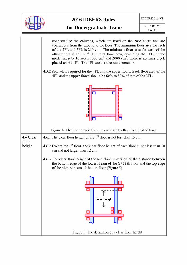
4.6 Clear floor height
4.6.1 The clear floor height of the 1st floor is not less than 15 cm.
4.6.2 Except the 1st floor, the clear floor height of each floor is not less than 10 cm and not larger than 12 cm.
4.6.3 The clear floor height of the i-th floor is defined as the distance between the bottom edge of the lowest beam of the (i+1)-th floor and the top edge of the highest beam of the i-th floor (Figure 5).
Figure 5. The definition of a clear floor height.

2016 IDEERS Rules
for Undergraduate Teams
IDEERS2016-V1
2016-06-24
8 of 21
4.7 Exterior clearance
4.7.1 There are openings for installing doors and windows on every floor of a real building. Therefore, every floor of the model must keep some exterior clearance Xi, in which there is no material/member installed along the perimeter Li of the floor (Figure 6). The ratio of Xi to Li for each floor should be no less than a certain value (to be specified later). It should be noted that both of the upward and downward projected lengths of bracings, walls and columns should be considered.
igure 6 Figure 7
4.7.2 Li (Figures 6 and 7) is the sum of the floor perimeter defining the floor area shown as Figure 4. Xi is the sum of the parts of the floor perimeter, which are not occupied by the projection of walls, bracings and columns.
4.7.3 The exterior clearance ratio of a floor is defined as:
ΣXi /ΣLi * 100% (1)
4.7.4 When the elevation of a floor in a certain direction is a trapezoid, Li is the larger length of the top side and the bottom side. For example, when the bottom side is wider than the top side (Figures 8a and 8b), Li is the length of the bottom side of the trapezoid. The corresponding Xi is the part of the bottom floor perimeter, which is not occupied by the projection of walls, bracings and inclined columns. On the contrary, when the top side is wider than the bottom side (Figures 9a and 9b), Li is the length of the top side of the trapezoid. The corresponding Xi is the part of the top floor perimeter, which is not occupied by the projection of walls, bracings and inclined columns.

2016 IDEERS Rules
for Undergraduate Teams
IDEERS2016-V1
2016-06-24
9 of 21
Figure 8a Figure 8b
Figure 9a Figure 9b
4.7.5 The space occupied by any materials, e.g., wooden sticks, cotton string, paper, etc., cannot be included into Xi when computing the exterior/interior clearance.
4.7.6 The exterior clearance ratio of each floor (ΣXi /ΣLi *100%), except the 1st floor, must be larger than 45%.
4.7.7 The exterior clearance ratio (ΣXi /ΣLi *100%) of the first floor must be larger than 70%.
4.8 Interior clearance
4.8.1 In order to keep passages inside a floor, any vertical cross section of a floor must not be fully blockaded. A fully blockaded vertical cross section is the width of the vertical cross section all occupied by the projection of materials/members. The width of the passage is the so-called interior clearance.
Figure 10 Figure 11

2016 IDEERS Rules
for Undergraduate Teams
IDEERS2016-V1
2016-06-24
10 of 21
4.8.2 The passage should be kept in all directions. That is to say, the vertical cross sections in all directions are not fully blockaded. For example, the projection of Figure 10 is shown as Figure 11. The dashed lines shown in Figure 11 are the passages.
4.8.3 When the distance between the end of a vertical member/material and the floor edge is less than 2.5 cm, this member/material is considered as an exterior bracing (Figure 12). An exterior bracing affects only the computation of the exterior clearance rather than the interior clearance.
Figure 12. An exterior bracing.
4.8.4 The interior clearance in any direction must be not less than 5 cm.
4.8.5 It should be noted that the interior bracings cannot touch with the mass blocks. The detail explanation of this item is stated in section 5.
4.8.6 The interior clearance of the 1st floor must be kept maximum. In other words, it is not allowed to install any interior braces or walls inside the 1st floor.
5. The placement of mass blocks
In reality, buildings are subjected to various types of loading. In this competition, mass blocks are used to simulate the vertical loading occurred in real buildings. The rules of placing the mass blocks are:
5.1 The material of the mass blocks is steel. The dimension of each mass block is 6.0 cm × 4.5 cm × 3.0 cm (±2 mm). The weight of each mass block is about 635 g. The average vertical loading on each unit floor area is 10 to 12 g/cm2 (denoted as wr) for all floors except the RFL and 1FL. The value of wr can be different for every floor. For the RFL, the average vertical loading on each unit floor area is 14 to 16 g/cm2 (denoted as wt). There is no need of mass blocks on 1FL. The required number of mass blocks on each floor is computed by using Equation (2). Then the computed value should be rounded off to the integer place.

2016 IDEERS Rules
for Undergraduate Teams
IDEERS2016-V1
2016-06-24
11 of 21
For all floors except the RFL and 1FL, the number of mass blocks = floor area (cm2) × wr / 635, where wr = 10 ~ 12. (2a)
For the RFL, the number of mass blocks = floor area (cm2) × wt / 635, where wt = 14 ~ 16. (2b)
5.2 All models should be loaded with at least the number of mass blocks computed from Rule 5.1. All of the mass blocks must be in compliance with Rules 5.3 to 5.6. Otherwise, the penalty weight is imposed on the model (Table 1). The number of mass blocks of each floor cannot be changed after the referee’s approval in the model inspection.
5.3 Mass blocks may be placed horizontally or vertically on the floors. Nevertheless, mass blocks cannot not be stacked up.
5.4 Mass blocks cannot extrudes beyond the boundary of a floor ≧ 5 mm, and cannot touch columns or bracings. If the mass blocks touch columns or bracings, the mass blocks would be treated as a part of the structure. Therefore, the clear floor height of that floor will be computed starting from the highest contact point instead of the top edge of the highest beam.
5.5 Mass blocks are fixed to the floors while mounting the model to the shaking table. Only hot-melt glue can be used to fix mass blocks to the floors. Other materials, such as paper, cotton string, rubber bands etc., are not permitted to fix mass blocks.
5.6 If one mass block installed onto the model floors is found to have one or more of the following conditions, 50 grams of penalty weight would be imposed for that particular mass block. In addition, that mass block will not be counted into the calculation of Efficiency Ratio.
5.6.1 A mass block extrudes beyond the boundary of a floor ≧ 5 mm.
5.6.2 A mass block touches columns, or bracings.
5.6.3 Mass blocks are stacked up vertically.
5.6.4 The actual number of installed mass blocks does not conform to the approved number shown in the Calculation Sheet (caused by either mistakes or uncompleted installation).
Example:
Floor no. Floor area
(cm2)
Calculated number of mass blocks Actual number of installed mass
blocks WeightingLower bound
(wt=14g, wr=10g) Upper bound
(wt=16g, wr=12g)RFL 200 4 5 5 3 6FL 200 3 4 4 3 5FL 250 4 5 5 2 4FL 250 4 5 5 2 3FL 320 5 6 6 1 2FL 350 6 7 6 1

2016 IDEERS Rules
for Undergraduate Teams
IDEERS2016-V1
2016-06-24
12 of 21
6. The grading rules
The criterion used for grading the performance of the models is the efficiency ratio (ER). The ER is computed as:
(3)
where:
I: The maximum seismic intensity resisted by the model (gal).
iW : The total weighted number of mass blocks supported by the model. The number of
mass blocks on different floors is multiplied by different weight factors (Figure 3).
The weight factor for the mass blocks on the 2FL and 3FL is equal to one. The weight
factor for the mass blocks on the 4FL and 5FL floors is two. The weight factor for the
mass blocks on the 6FL and upper floors is three.
MM: The mass of the model itself (including the base board, but excluding the mass blocks)
MB: The mass of the base board.
MP: The penalty mass, which penalizes the violation of the competing rules. The detail of the penalty mass is shown in Table 1.
PBM
i
MMM
WIRatioEfficiencyER

2016 IDEERS Rules
for Undergraduate Teams
IDEERS2016-V1
2016-06-24
13 of 21
Table 1. The penalty mass.
Rule No. Violations Penalty mass 15.3 Clean up the working area and arrange the tools in order 500 g 4.2.1 4.2.2
The site area of the model and the clearance along the edge of the base board ( 3 cm)
500 g
4.4.1 Except the 1FL, there are at least four floors can be loaded with mass blocks.
500 g
4.4.2 The total height of the model (45 cm H 70 cm) 200 g
4.5.1 Except the 1FL,the total floor area (1000 cm2 A 2000 cm2) 100 g
4.8.6 The interior clearances for the 1FL 500 g
5.1 5.6
Violation of mass block installation requirements 50 g /block
4.6.1 4.6.2
The clear floor height (1FL ≧ 15 cm, 10 cm ≦ all other floors ≦ 12 cm) 50 g / cm
4.7.6 4.7.7
Exterior clearance ΣXi /ΣLi (1FL>70%, OTHER FLRS > 45%) 10 g / %
4.8.4 Interior clearance (must 5 cm for all floors) 100 g / cm 4.4.1 Floor area (2-3FL: 250 cm2; 4FL-RFL 150 cm2) 5 g / cm2
4.5.2 Each floor area of the 4th and the upper floors should be 60% to 80% of that of the 3FL.
10g / %
Example: There is a model with the mass of the model itself, MM, equal to 750 g, and the mass of the base board, MB, equal to 275 g. In addition, the penalty mass, MP, is 50 g because the clear height of one floor is only 9.6 cm. There are 6, 6, 5, 5, 4, and 5 mass blocks placed on the 2FL, 3FL, 4FL, 5FL, 6FL, and RFL, respectively. This model passes the shaking test with a PGA equal to 700 gal (i.e., I =700), but fails at the subsequent shaking test with a PGA equal to 800 gal. The efficiency ratio of this model is computed as:
67.7850275750
)353425251616(700
pBM
i
MMM
WIER
7. Mounting models onto the shaking table
Before the models are tested on the shaking table, there are periods allowing all teams to mount their models onto the shaking table and fix mass blocks on the floors of models.
7.1 Only two members of each team are allowed to mount their model onto the shaking table and fix the mass blocks. This task should be completed within 15 minutes. The team members are responsible for the completion of this task.

2016 IDEERS Rules
for Undergraduate Teams
IDEERS2016-V1
2016-06-24
14 of 21
7.2 The organizer will provide a screwdriver and screws to each team for mounting the model onto the shaking table.
7.3 The organizer will provide a hot-melt glue gun and hot-melt glue to each team for fixing the mass blocks on the floors of the model.
7.4 The materials and tools not provided by the organizer cannot be used to mount the models onto the shaking table and fix the mass blocks.
7.5 During the period of mounting the models onto the shaking table and fixing the mass blocks, it is not allowed to strengthen the structure of the model.
7.6 The team members mounting the models onto the shaking table should be careful not to touch other teams’ models, which have already been mounted on the table.
7.7 After all teams completed the task of mounting their models onto the shaking table and fixing the mass blocks, IDEERS staff will check whether or not all models are safely mounted on the shaking table and make necessary reinforcement. Nevertheless, each team is still completely responsible for the fixture of the model and the mass blocks.
7.8 The judges will examine all models mounted on the shaking table. The model with the following conditions stated in 7.8.1 to 7.8.3 will be required to make modifications of the model within an allowed time period. Otherwise, a certain penalty will be given to the model by the judges. Sometimes, in the worst case, the team may be disqualified for ranking in this contest.
7.8.1 The number of mass blocks on each floor is not consistent with that reported in the check table.
7.8.2 Mass blocks are attached to columns/bracings by using hot-melt glue.
7.8.3 Mass blocks are beyond the boundary of the supporting floor ≧ 5 mm.
Figure 13. The orientation of the model fixed on the shaking table.

2016 IDEERS Rules
for Undergraduate Teams
IDEERS2016-V1
2016-06-24
15 of 21
7.9 The side of the base board marked with a sticker is where the model should be built on. In addition, when mounting the model onto the shaking table, the sticker should be on the northwest corner (shown as Figure 13). If there is any question about the relative positions or directions shown in Figure 13, please ask the staffs/judges for assistance.
7.10 The base board is fixed to the shaking table by using a metal plate (Figure 14). Please note the orientation of the metal plate because the layouts of the holes on the four sides of the metal plate are not the same.
Figure 14. The metal plate for fixing the base board
8. Loading protocols
All models will be tested simultaneously on the shaking table. The artificial earthquakes generated by the shaking table contain a broadband of sweeping excitation frequencies. The intensity of each artificial earthquake is represented by using the peak ground acceleration (PGA). The PGA increases from one test to another. Figure 15 shows the two components of the displacement time histories of the artificial earthquake with the PGA equal to 250 gal.
8.1 There will be at most six tests, in which the PGAs are arranged in the sequence of 250 gal, 400 gal, 500 gal, 600 gal, 700 gal, 800 gal.
8.2 The teams whose models pass the test with the PGA equal to 400 gal, which is equivalent to an earthquake with the intensity VI in Taiwan, will receive the Quake-Resistant Certificate.
8.3 Only the models passing the test with the PGA equal to 600 gal are qualified for ranking in this contest.
振動台控制室(Control Room)

2016 IDEERS Rules
for Undergraduate Teams
IDEERS2016-V1
2016-06-24
16 of 21
8.4 The bidirectional time histories of the artificial earthquakes are available on the IDEER’s website. All teams are encouraged to download these data.
8.5 The mentioned directions are according to those specified in the lab. Figure 13 shows the directions and the orientation for mounting the models to the shaking table.
0 20 40 60 80
Time (sec)
-15
-10
-5
0
5
10
15
Dis
pla
cem
en
t (m
m)
Figure 14. The E-W and N-S components of displacement time histories of the artificial earthquake with the PGA equal to 250 gal.
9. The failure criteria
A model will be judged to fail the test when the following conditions occur:
9.1 Any floor is unstable or collapsed.
9.2 Any mass block falls off, significantly dislocates, sways, or rocks.
9.3 The number of columns detached from the base board is larger than or equal to one half of
the total number of columns.
9.4 The residual displacement of the inclined model, which is the horizontal distance
measured from the original roof position to the final roof position, is greater than or equal
to 10 cm.
9.5 The jury has the consensus that a model fails in the test.

2016 IDEERS Rules
for Undergraduate Teams
IDEERS2016-V1
2016-06-24
17 of 21
10. The check frame
A check frame shown as Figure 16 is provided to each team by the organizer. In order to make sure that the models are built within the allowable area, all teams are suggested to utilize the check frame by putting this frame through the models. Every horizontal cross section of the model should be within the opening of the check frame. The model violating this rule will be punished by adding 500 g penalty mass.
Figure 16. The shape of the check frame.
11. The Exhibition Object
Each team must prepare an exhibition object displaying the design concept and creativity of the model. This exhibition object is done before this two-day competition. The object could be either two-dimensional or three-dimensional. The way of exhibition could be in a static and/or dynamic style. The space for this exhibition is limited to 35 cm (height) × 25 cm (width) × 25 cm (depth) shown as Figure 17. The Design-Concept Exhibition Award is granted based on the clarity and creativity of displaying the design concept of the model. The affiliation of the team including the department and the university/college should be presented in the exhibition object. If the exhibition object uses electronic products, the team is responsible for the safe keeping of the electronic products. In addition, the team is responsible for the power supply to the electronic products.

2016 IDEERS Rules
for Undergraduate Teams
IDEERS2016-V1
2016-06-24
18 of 21
Figure 17. The allowable exhibition space
12. The team flag
Each team must design a team flag, which is installed on the model during the first day of this contest. This flag may be drawn before or during this contest. All possible shapes of this flag are allowed. Nevertheless, the size of this flag should be no larger than that of a sheet of A6-size paper (14.4 cm L × 10.5 cm W, i.e., a quarter of an A4-size paper). This flag can be installed on the model by using any provided materials, such as the bamboo sticks.
13. Model inspection
The period of the model inspection begins at the end of the model construction and ends at the start of the shaking table tests.
13.1 The procedures of the model inspection are: (1) The host calls the team number. (2) The team members weigh the model. (3) The judges inspect the model and then fill in the inspection form. (4) The staffs take a picture of the model and the exhibition object. (5) The team members place the model and the exhibition object on the designated table for displaying. On the second day, all competitors and judges vote models and exhibition objects for some special prizes. (6) Two team members mount the model onto the shaking table for the tests.
13.2 The items submitted to the judges for inspection are: (1) the model, (2) the model inspection form, (3) the calculation sheet of the floor area, (4) the check frame and (5) the exhibition object. All of the abovementioned items are taken to the judges by two members of each team.

2016 IDEERS Rules
for Undergraduate Teams
IDEERS2016-V1
2016-06-24
19 of 21
13.3 During the model inspection period, judges have the right to request the model to be modified or to make penalties to the model if the model violates the contest rules. During the two-day contest, jury has the right to re-inspect any models. The team, whose model needs to be re-inspected by the jury, cannot reject this request.
14. Architectural Aesthetic Awards, Structural Design Awards, and Design-Concept Exhibition Awards
14.1 Aesthetic Architecture Awards are granted on the basis of the architectural features, the efficiency of using the site area, and the plan of inner space. The jury chooses at most three models for these awards. The team winning this award will be granted NT$5000 and a certificate for each team member. The evaluated items and the corresponding weights for these awards are:
item weight contents
architectural features 70% Aesthetic of architecture Architectural feature and creativity
the efficiency of using the site area and the plan of inner space
30% The rationality and comfort of inner space The rationality of using the site area
14.2 Structural Design Awards are granted on the basis of the structural design of models, the concept and creativity of seismic resistance. The jury chooses at most three models for these awards. The team winning this award will be granted NT$5000 and a certificate for each team member. The evaluated items and the corresponding weights for these awards are:
item weight contents
Structural design 70% The arrangement of structural members The rationality of loading path
the concept and creativity of seismic resistance
30%
The rationality of the concept of seismic resistance
The creativity of the concept of seismic resistance
14.3 Design-Concept Exhibition Awards are granted on the basis of the clarity and creativity of displaying the design concept of the model. The jury chooses at most three models for these awards. The team winning this award will be granted NT$3000 and a certificate for each team member. The evaluated items and the corresponding weights for these awards are:

2016 IDEERS Rules
for Undergraduate Teams
IDEERS2016-V1
2016-06-24
20 of 21
item weight contents Introduction of the design concept
60% The clarity of introducing the design concept
The way of showing the design concept
40%
The vividness of the way showing the design concept
The creativity of the way showing the design concept
15. Special notices
15.1 In comparison with the contest rules adopted in previous years, there are significant modifications in this year’s contest rules. All participants should read all contest rules in detail. The main modifications of this year’s contest rules are:
15.1.1 The shape of building site has been changed.
15.1.2 The floor area of each floor and the total floor area of the model have been changed.
15.1.3 The requirement of setback for the 4FL to RFL.
15.1.4 The average vertical loading on each unit floor area is 10 to 12 g/cm2 for all floors except the RFL and 1FL. For the RFL, the average vertical loading on each unit floor area is 14 to 16 g/cm2. The required number of mass blocks on each floor is computed accordingly.
15.1.5 The minimum number of mass blocks for each floor is computed from Equation 2. Then the computed number should be rounded off to the integer place. There is no upper limit for the total number of mass blocks.
15.1.6 In order to check the number of mass blocks, the relationships between the floor area and the number of mass blocks are listed in the below two tables.
(a) The RFL
Number of mass
block Lower limit < floor area < Upper limit
3 150 < floor area < 158.75
4 150 < floor area < 204.11
5 178.59 < floor area < 249.46
6 218.28 < floor area < 294.82
7 257.97 < floor area < 320
8 297.66 < floor area < 320

2016 IDEERS Rules
for Undergraduate Teams
IDEERS2016-V1
2016-06-24
21 of 21
(b) All floors except the RFL and 1FL
Number of mass
block Lower limit < floor area < Upper limit
3 150 < floor area < 222.25
4 185.21 < floor area < 285.75
5 238.13 < floor area < 349.25
6 291.04 < floor area < 400
7 343.96 < floor area < 400
8 396.88 < floor area < 400
15.2 In order to save the inspection time, each team should complete the model inspection form, the calculation sheets of the floor area and the number of mass blocks before submitting the model to the judges for inspection.
15.3 Each team must clean their working area and arrange the tools in order after completing their models. Otherwise, the team will be punished by adding a penalty weight equal to 500 g.

2016 IDEERS- Undergraduate Teams
Floor Area Calculation Form
IDEERS2016
2016-06-24
1 of 2
Floor
No.
Floor Area
(cm2) Floor Dimension Drawing & Floor Area Calculation
__FL
__FL
__FL
__FL

2016 IDEERS- Undergraduate Teams
Floor Area Calculation Form
IDEERS2016
2016-06-24
2 of 2
__FL
__FL
__FL
__FL
總面積
Total

Check Table of 2016 IDEERS Undergraduate Teams Team No. School Name
MM (Mass of the Model) g Reviewer
MB (Mass of the Base Board) g
MP (Weight Penalty) g
MM - MB + MP = g
1.Field cleanup &tools collation Penalty (500g)
□ O.K. □ N.G.
2.Building range & board boundary clear width ( ≥ 3 cm)
Penalty (500g)
cm
3. Except the 1FL, there are at least four floors can be loaded with mass blocks.
Penalty (500g)
□ O.K. □ N.G.
4.Height (45cm ≤ H ≤ 70cm) Penalty (200g)
cm
5. Except the 1FL, total floor area (1000 cm2≤A≤2000cm2)
Penalty (100g)
cm2
6. Interior clearance of 1FL Penalty (500g)
□ O.K. □ N.G. 7. Violation of mass block installation
requirements Penalty (50g /
per Steel Block)
blocks 8.Seback of floor areas (the floor area of
4FL and upper floors is 60~80% of that of 3FL)
Penalty (10g / %)
9.Clear height ( 1FL≥15cm; 10cm≤ OTHER FLRS ≤ 12cm)
Penalty (50g/cm)
__FL cm g
__FL cm g
5FL cm g
4FL cm g
3FL cm g
2FL cm g
1FL cm g
10.Exterior clearance ΣXi /ΣLi (1FL>70%, OTHER FLRS > 45%) Penalty
(10g/ 1%) ΣLi ΣXi ΣXi/ΣLi
__FL % g
__FL % g
5FL % g
4FL % g
3FL % g
2FL % g
1FL % g
11.Interior clearance (≧5cm) Penalty (100g/cm)
__FL cm g
__FL cm g
5FL cm g
4FL cm g
3FL cm g
2FL cm g
1FL cm g 2
12.Floor area (each floor) Penalty
(5g/cm2)
__FL cm2 ≥ 150cm2 g
__FL cm2 ≥ 150cm2 g
5FL cm2 ≥ 150cm2 g
4FL cm2 ≥ 150cm2 g
3FL cm2 ≥ 250cm2 g
2FL cm2 ≥ 250cm2 g
Total cm2
13.Number of steel blocks of each floor
Weighting Wi
__FL x 3 =
__FL x 3 =
5FL x 2 =
4FL x 2 =
3FL x 1 =
2FL x 1 =
Total ΣWi =
Unit: Area: cm2 Length & Height: cm Mass: gram