electricity and magnetism mutual inductance...
TRANSCRIPT

Electricity and MagnetismMotional EMFFaraday’s Law
Lana Sheridan
De Anza College
Mar 6, 2018

Last time
• relativity and electromagnetic fields

Overview
• motional emf
• induction
• Faraday’s law
• Lenz’s law

Magnetic Moment of Atoms
In atoms with many electrons, the electrons tend to cancel outeach other’s magnetic moments, but outer-shell, unpaired electronscan contribute a significant magnetic moment.
The particles in the nucleus also have magnetic moments, but theyare much smaller.
Most of an atom’s magnetic moment comes from unpairedelectons.
These tiny magnetic moments add up to big effects in bulkmaterials.

Three Types of Bulk Magnetism
• ferromagnetism
• paramagnetism
• diamagnetism

Ferromagnetism
Atoms of ferromagnetic materials have non-zero magneticmoments.
Interactions between outer electrons in different atoms causesalignment of each atom’s magnetic moment.
Magnetic moments reenforce each other and will tend tospontaneously align within domains.
Examples of ferromagnetic materials:
• iron
• nickel
• cobalt
• gadolinium
• dysprosium

Ferromagnetism
No external B-field
30.6 Magnetism in Matter 921
oriented so that the net magnetic moment is zero as in Figure 30.26a. When the sam-ple is placed in an external magnetic field B
S, the size of those domains with mag-
netic moments aligned with the field grows, which results in a magnetized sample as in Figure 30.26b. As the external field becomes very strong as in Figure 30.26c, the domains in which the magnetic moments are not aligned with the field become very small. When the external field is removed, the sample may retain a net magnetiza-tion in the direction of the original field. At ordinary temperatures, thermal agita-tion is not sufficient to disrupt this preferred orientation of magnetic moments. When the temperature of a ferromagnetic substance reaches or exceeds a critical temperature called the Curie temperature, the substance loses its residual magne-tization. Below the Curie temperature, the magnetic moments are aligned and the substance is ferromagnetic. Above the Curie temperature, the thermal agitation is great enough to cause a random orientation of the moments and the substance becomes paramagnetic. Curie temperatures for several ferromagnetic substances are given in Table 30.2.
ParamagnetismParamagnetic substances have a weak magnetism resulting from the presence of atoms (or ions) that have permanent magnetic moments. These moments inter-act only weakly with one another and are randomly oriented in the absence of an external magnetic field. When a paramagnetic substance is placed in an external magnetic field, its atomic moments tend to line up with the field. This alignment process, however, must compete with thermal motion, which tends to randomize the magnetic moment orientations.
DiamagnetismWhen an external magnetic field is applied to a diamagnetic substance, a weak magnetic moment is induced in the direction opposite the applied field, causing diamagnetic substances to be weakly repelled by a magnet. Although diamagne-tism is present in all matter, its effects are much smaller than those of paramagnet-ism or ferromagnetism and are evident only when those other effects do not exist. We can attain some understanding of diamagnetism by considering a classical model of two atomic electrons orbiting the nucleus in opposite directions but with the same speed. The electrons remain in their circular orbits because of the attractive electrostatic force exerted by the positively charged nucleus. Because the magnetic moments of the two electrons are equal in magnitude and opposite in direction, they cancel each other and the magnetic moment of the atom is zero. When an external magnetic field is applied, the electrons experience an additional mag-netic force q vS 3 B
S. This added magnetic force combines with the electrostatic
force to increase the orbital speed of the electron whose magnetic moment is anti-parallel to the field and to decrease the speed of the electron whose magnetic moment is parallel to the field. As a result, the two magnetic moments of the elec-trons no longer cancel and the substance acquires a net magnetic moment that is opposite the applied field.
a
c
b
In an unmagnetized substance, the atomic magnetic dipoles are randomly oriented.
BS
BS
dAS
BS
When an external field is applied, the domains with components of magnetic moment in the same direction as grow larger, giving the sample a net magnetization.
BS
BS
As the field is made even stronger, the domains with magnetic moment vectors not aligned with the external field become very small.
Figure 30.26 Orientation of magnetic dipoles before and after a magnetic field is applied to a fer-romagnetic substance.
Table 30.2 Curie Temperatures for Several Ferromagnetic SubstancesSubstance TCurie (K)
Iron 1 043Cobalt 1 394Nickel 631Gadolinium 317Fe2O3 893

FerromagnetismApplied external B-field
30.6 Magnetism in Matter 921
oriented so that the net magnetic moment is zero as in Figure 30.26a. When the sam-ple is placed in an external magnetic field B
S, the size of those domains with mag-
netic moments aligned with the field grows, which results in a magnetized sample as in Figure 30.26b. As the external field becomes very strong as in Figure 30.26c, the domains in which the magnetic moments are not aligned with the field become very small. When the external field is removed, the sample may retain a net magnetiza-tion in the direction of the original field. At ordinary temperatures, thermal agita-tion is not sufficient to disrupt this preferred orientation of magnetic moments. When the temperature of a ferromagnetic substance reaches or exceeds a critical temperature called the Curie temperature, the substance loses its residual magne-tization. Below the Curie temperature, the magnetic moments are aligned and the substance is ferromagnetic. Above the Curie temperature, the thermal agitation is great enough to cause a random orientation of the moments and the substance becomes paramagnetic. Curie temperatures for several ferromagnetic substances are given in Table 30.2.
ParamagnetismParamagnetic substances have a weak magnetism resulting from the presence of atoms (or ions) that have permanent magnetic moments. These moments inter-act only weakly with one another and are randomly oriented in the absence of an external magnetic field. When a paramagnetic substance is placed in an external magnetic field, its atomic moments tend to line up with the field. This alignment process, however, must compete with thermal motion, which tends to randomize the magnetic moment orientations.
DiamagnetismWhen an external magnetic field is applied to a diamagnetic substance, a weak magnetic moment is induced in the direction opposite the applied field, causing diamagnetic substances to be weakly repelled by a magnet. Although diamagne-tism is present in all matter, its effects are much smaller than those of paramagnet-ism or ferromagnetism and are evident only when those other effects do not exist. We can attain some understanding of diamagnetism by considering a classical model of two atomic electrons orbiting the nucleus in opposite directions but with the same speed. The electrons remain in their circular orbits because of the attractive electrostatic force exerted by the positively charged nucleus. Because the magnetic moments of the two electrons are equal in magnitude and opposite in direction, they cancel each other and the magnetic moment of the atom is zero. When an external magnetic field is applied, the electrons experience an additional mag-netic force q vS 3 B
S. This added magnetic force combines with the electrostatic
force to increase the orbital speed of the electron whose magnetic moment is anti-parallel to the field and to decrease the speed of the electron whose magnetic moment is parallel to the field. As a result, the two magnetic moments of the elec-trons no longer cancel and the substance acquires a net magnetic moment that is opposite the applied field.
a
c
b
In an unmagnetized substance, the atomic magnetic dipoles are randomly oriented.
BS
BS
dAS
BS
When an external field is applied, the domains with components of magnetic moment in the same direction as grow larger, giving the sample a net magnetization.
BS
BS
As the field is made even stronger, the domains with magnetic moment vectors not aligned with the external field become very small.
Figure 30.26 Orientation of magnetic dipoles before and after a magnetic field is applied to a fer-romagnetic substance.
Table 30.2 Curie Temperatures for Several Ferromagnetic SubstancesSubstance TCurie (K)
Iron 1 043Cobalt 1 394Nickel 631Gadolinium 317Fe2O3 893

Ferromagnetism
Strong external B-field
30.6 Magnetism in Matter 921
oriented so that the net magnetic moment is zero as in Figure 30.26a. When the sam-ple is placed in an external magnetic field B
S, the size of those domains with mag-
netic moments aligned with the field grows, which results in a magnetized sample as in Figure 30.26b. As the external field becomes very strong as in Figure 30.26c, the domains in which the magnetic moments are not aligned with the field become very small. When the external field is removed, the sample may retain a net magnetiza-tion in the direction of the original field. At ordinary temperatures, thermal agita-tion is not sufficient to disrupt this preferred orientation of magnetic moments. When the temperature of a ferromagnetic substance reaches or exceeds a critical temperature called the Curie temperature, the substance loses its residual magne-tization. Below the Curie temperature, the magnetic moments are aligned and the substance is ferromagnetic. Above the Curie temperature, the thermal agitation is great enough to cause a random orientation of the moments and the substance becomes paramagnetic. Curie temperatures for several ferromagnetic substances are given in Table 30.2.
ParamagnetismParamagnetic substances have a weak magnetism resulting from the presence of atoms (or ions) that have permanent magnetic moments. These moments inter-act only weakly with one another and are randomly oriented in the absence of an external magnetic field. When a paramagnetic substance is placed in an external magnetic field, its atomic moments tend to line up with the field. This alignment process, however, must compete with thermal motion, which tends to randomize the magnetic moment orientations.
DiamagnetismWhen an external magnetic field is applied to a diamagnetic substance, a weak magnetic moment is induced in the direction opposite the applied field, causing diamagnetic substances to be weakly repelled by a magnet. Although diamagne-tism is present in all matter, its effects are much smaller than those of paramagnet-ism or ferromagnetism and are evident only when those other effects do not exist. We can attain some understanding of diamagnetism by considering a classical model of two atomic electrons orbiting the nucleus in opposite directions but with the same speed. The electrons remain in their circular orbits because of the attractive electrostatic force exerted by the positively charged nucleus. Because the magnetic moments of the two electrons are equal in magnitude and opposite in direction, they cancel each other and the magnetic moment of the atom is zero. When an external magnetic field is applied, the electrons experience an additional mag-netic force q vS 3 B
S. This added magnetic force combines with the electrostatic
force to increase the orbital speed of the electron whose magnetic moment is anti-parallel to the field and to decrease the speed of the electron whose magnetic moment is parallel to the field. As a result, the two magnetic moments of the elec-trons no longer cancel and the substance acquires a net magnetic moment that is opposite the applied field.
a
c
b
In an unmagnetized substance, the atomic magnetic dipoles are randomly oriented.
BS
BS
dAS
BS
When an external field is applied, the domains with components of magnetic moment in the same direction as grow larger, giving the sample a net magnetization.
BS
BS
As the field is made even stronger, the domains with magnetic moment vectors not aligned with the external field become very small.
Figure 30.26 Orientation of magnetic dipoles before and after a magnetic field is applied to a fer-romagnetic substance.
Table 30.2 Curie Temperatures for Several Ferromagnetic SubstancesSubstance TCurie (K)
Iron 1 043Cobalt 1 394Nickel 631Gadolinium 317Fe2O3 893

Paramagnetism
Atoms of paramagnetic materials have non-zero dipole moments,but electrons of different atoms do not interact with each other.
They can interact with a strong magnetic field, and will align withthe field.
Paramagnetic effects tend to be much smaller than ferromagneticones.
Examples of paramagnetic materials:
• Tungsten
• Cesium
• Aluminium
• Lithium
• Magnesium
• Sodium

Paramagnetism
Liquid oxygenstream deflectedin a strongmagnetic field.The streamcollects in thefield.
1Image created by Pieter Kuiper.
DiamagnetismDiamagnetism occurs in all materials, but is a weak effect, so it is“drowned out” if a material is ferro- or paramagnetic.
It is the dominant (but weak) effect when the net magneticmoment of a material’s atoms is zero.
The field magnetizes the atoms and the resulting magneticmoments oppose the external magnetic field.
Examples of diamagnetic materials:
• Pyrolytic carbon
• Bismuth
• Mercury
• Silver
• diamond (form of Carbon)
• water
Also superconductors can be said to exhibit extreme diamagnetism.

Diamagnetism
1Levitating pyrolytic carbon on neodymium magnets. Image by Splarka.

Diamagnetism
1Magnet photo by Mai-Linh Doan, Wikipedia; Frog photo by LijnisNelemans/High Field Magnet Laboratory/Radboud University Nijmeg.

Motional EMFIf a conductor moves through a magnetic field at an angle to thefield, an emf is induced across the conductor.
940 Chapter 31 Faraday’s Law
The straight conductor of length , shown in Figure 31.7 is moving through a uni-form magnetic field directed into the page. For simplicity, let’s assume the conductor is moving in a direction perpendicular to the field with constant velocity under the influence of some external agent. From the magnetic version of the particle in a field model, the electrons in the conductor experience a force F
SB 5 q vS 3 B
S (Eq. 29.1)
that is directed along the length ,, perpendicular to both vS and BS
. Under the influence of this force, the electrons move to the lower end of the conductor and accumulate there, leaving a net positive charge at the upper end. As a result of this charge separation, an electric field E
S is produced inside the conductor. Therefore,
the electrons are also described by the electric version of the particle in a field model. The charges accumulate at both ends until the downward magnetic force qvB on charges remaining in the conductor is balanced by the upward electric force qE. The electrons are then described by the particle in equilibrium model. The condi-tion for equilibrium requires that the forces on the electrons balance:
qE 5 qvB or E 5 vB
The magnitude of the electric field produced in the conductor is related to the potential difference across the ends of the conductor according to the relationship DV 5 E, (Eq. 25.6). Therefore, for the equilibrium condition,
DV 5 E, 5 B,v (31.4)
where the upper end of the conductor in Figure 31.7 is at a higher electric potential than the lower end. Therefore, a potential difference is maintained between the ends of the conductor as long as the conductor continues to move through the uni-form magnetic field. If the direction of the motion is reversed, the polarity of the potential difference is also reversed. A more interesting situation occurs when the moving conductor is part of a closed conducting path. This situation is particularly useful for illustrating how a changing magnetic flux causes an induced current in a closed circuit. Consider a circuit con-sisting of a conducting bar of length , sliding along two fixed, parallel conducting rails as shown in Figure 31.8a. For simplicity, let’s assume the bar has zero resistance and the stationary part of the circuit has a resistance R. A uniform and constant magnetic field B
S is applied perpendicular to the plane of the circuit. As the bar is
pulled to the right with a velocity vS under the influence of an applied force FS
app, free charges in the bar are moving particles in a magnetic field that experience a magnetic force directed along the length of the bar. This force sets up an induced current because the charges are free to move in the closed conducting path. In this case, the rate of change of magnetic flux through the circuit and the corresponding
BinS
!
!!
""
ES
FeS
FBS
vS
Due to the magnetic force on electrons, the ends of the conductor become oppositely charged, which establishes an electric field in the conductor.
In steady state, the electric and magnetic forces on an electron in the conductor are balanced.
"
Figure 31.7 A straight electrical conductor of length , moving with a velocity vS through a uniform magnetic field B
S directed perpen-
dicular to vS.
a b
vS
R # B!v
I
I
R
x
!
I
e
A counterclockwise current I is induced in the loop. The magnetic force on the bar carrying this current opposes the motion.
FappS
FBS
FBS
BinS
"
!
Figure 31.8 (a) A conducting bar sliding with a velocity vS along two conducting rails under the action of an applied force F
Sapp.
(b) The equivalent circuit dia-gram for the setup shown in (a).
There are two ways to see this:
1 force on conduction charges F = q v × B
2 (relativity: in the rest frame of the conductor there is also anelectric field as soon as the conductor moves)

Motional EMF
940 Chapter 31 Faraday’s Law
The straight conductor of length , shown in Figure 31.7 is moving through a uni-form magnetic field directed into the page. For simplicity, let’s assume the conductor is moving in a direction perpendicular to the field with constant velocity under the influence of some external agent. From the magnetic version of the particle in a field model, the electrons in the conductor experience a force F
SB 5 q vS 3 B
S (Eq. 29.1)
that is directed along the length ,, perpendicular to both vS and BS
. Under the influence of this force, the electrons move to the lower end of the conductor and accumulate there, leaving a net positive charge at the upper end. As a result of this charge separation, an electric field E
S is produced inside the conductor. Therefore,
the electrons are also described by the electric version of the particle in a field model. The charges accumulate at both ends until the downward magnetic force qvB on charges remaining in the conductor is balanced by the upward electric force qE. The electrons are then described by the particle in equilibrium model. The condi-tion for equilibrium requires that the forces on the electrons balance:
qE 5 qvB or E 5 vB
The magnitude of the electric field produced in the conductor is related to the potential difference across the ends of the conductor according to the relationship DV 5 E, (Eq. 25.6). Therefore, for the equilibrium condition,
DV 5 E, 5 B,v (31.4)
where the upper end of the conductor in Figure 31.7 is at a higher electric potential than the lower end. Therefore, a potential difference is maintained between the ends of the conductor as long as the conductor continues to move through the uni-form magnetic field. If the direction of the motion is reversed, the polarity of the potential difference is also reversed. A more interesting situation occurs when the moving conductor is part of a closed conducting path. This situation is particularly useful for illustrating how a changing magnetic flux causes an induced current in a closed circuit. Consider a circuit con-sisting of a conducting bar of length , sliding along two fixed, parallel conducting rails as shown in Figure 31.8a. For simplicity, let’s assume the bar has zero resistance and the stationary part of the circuit has a resistance R. A uniform and constant magnetic field B
S is applied perpendicular to the plane of the circuit. As the bar is
pulled to the right with a velocity vS under the influence of an applied force FS
app, free charges in the bar are moving particles in a magnetic field that experience a magnetic force directed along the length of the bar. This force sets up an induced current because the charges are free to move in the closed conducting path. In this case, the rate of change of magnetic flux through the circuit and the corresponding
BinS
!
!!
""
ES
FeS
FBS
vS
Due to the magnetic force on electrons, the ends of the conductor become oppositely charged, which establishes an electric field in the conductor.
In steady state, the electric and magnetic forces on an electron in the conductor are balanced.
"
Figure 31.7 A straight electrical conductor of length , moving with a velocity vS through a uniform magnetic field B
S directed perpen-
dicular to vS.
a b
vS
R # B!v
I
I
R
x
!
I
e
A counterclockwise current I is induced in the loop. The magnetic force on the bar carrying this current opposes the motion.
FappS
FBS
FBS
BinS
"
!
Figure 31.8 (a) A conducting bar sliding with a velocity vS along two conducting rails under the action of an applied force F
Sapp.
(b) The equivalent circuit dia-gram for the setup shown in (a).
Once the charge distribution reachesequilibrium, the net force on eachcharge:
Fnet = q(E + v × B) = 0
E = vB (v ⊥ B)
E
`= vB
E = vB`

Motional emf in rotating bar (Ex 31.4)
A conducting bar of length `, rotates with a constant angularspeed ω about a pivot at one end. A uniform magnetic field B isdirected perpendicular to the plane of rotation. Find the motionalemf induced between the ends of the bar.
31.2 Motional emf 943
Answer Increasing vi would make the bar move farther. Increasing R would decrease the current and therefore the magnetic force, making the bar move farther. Decreasing B would decrease the magnetic force and make the bar move farther. Which method is most effective, though?
Rearrange terms:dvv
5 2aB 2, 2
mRb dt
Finalize This result is the same expression to be integrated that we found in part (A).
Suppose you wished to increase the distance through which the bar moves between the time it is initially projected and the time it essentially comes to rest. You can do so by changing one of three variables—vi , R, or B—by a factor of 2 or 12 . Which variable should you change to maximize the distance, and would you double it or halve it?
WHAT IF ?
Use Equation (1) to find the distance the bar moves by integration:
v 5dxdt
5 vi e2t/t
x 5 3`
0vi e2t/t dt 5 2vi te2t/t ` `
0
5 2vi t 10 2 1 2 5 vi t 5 vi a mRB 2,2b
This expression shows that doubling vi or R will double the distance. Changing B by a factor of 12, however, causes the
distance to be four times as great!
Example 31.4 Motional emf Induced in a Rotating Bar
A conducting bar of length , rotates with a con-stant angular speed v about a pivot at one end. A uniform magnetic field B
S is directed perpendic-
ular to the plane of rotation as shown in Figure 31.10. Find the motional emf induced between the ends of the bar.
Conceptualize The rotating bar is different in nature from the sliding bar in Figure 31.8. Con-sider a small segment of the bar, however. It is a short length of conductor moving in a magnetic field and has an emf generated in it like the sliding bar. By thinking of each small segment as a source of emf, we see that all segments are in series and the emfs add.
Categorize Based on the conceptualization of the problem, we approach this example as we did in the discussion lead-ing to Equation 31.5, with the added feature that the short segments of the bar are traveling in circular paths.
S O L U T I O N
BinS
!
drr
Pivot
vS
Figure 31.10 (Example 31.4) A conducting bar rotating around a pivot at one end in a uniform magnetic field that is perpendicular to the plane of rotation. A motional emf is induced between the ends of the bar.
continued
Analyze Evaluate the magnitude of the emf induced in a segment of the bar of length dr having a velocity vS from Equation 31.5:
de 5 Bv dr
▸ 31.3 c o n t i n u e d
Find the total emf between the ends of the bar by adding the emfs induced across all segments:
e 5 3Bv dr
The tangential speed v of an element is related to the angular speed v through the relationship v 5 rv (Eq. 10.10); use that fact and integrate:
e 5 B 3v dr 5 Bv3,
0 r dr 5 1
2 Bv,2

Motional emf in rotating bar (Ex 31.4)Each infinitesimal slice of the bar, dr, is moving at a differentspeed v(r) = rω.
31.2 Motional emf 943
Answer Increasing vi would make the bar move farther. Increasing R would decrease the current and therefore the magnetic force, making the bar move farther. Decreasing B would decrease the magnetic force and make the bar move farther. Which method is most effective, though?
Rearrange terms:dvv
5 2aB 2, 2
mRb dt
Finalize This result is the same expression to be integrated that we found in part (A).
Suppose you wished to increase the distance through which the bar moves between the time it is initially projected and the time it essentially comes to rest. You can do so by changing one of three variables—vi , R, or B—by a factor of 2 or 12 . Which variable should you change to maximize the distance, and would you double it or halve it?
WHAT IF ?
Use Equation (1) to find the distance the bar moves by integration:
v 5dxdt
5 vi e2t/t
x 5 3`
0vi e2t/t dt 5 2vi te2t/t ` `
0
5 2vi t 10 2 1 2 5 vi t 5 vi a mRB 2,2b
This expression shows that doubling vi or R will double the distance. Changing B by a factor of 12, however, causes the
distance to be four times as great!
Example 31.4 Motional emf Induced in a Rotating Bar
A conducting bar of length , rotates with a con-stant angular speed v about a pivot at one end. A uniform magnetic field B
S is directed perpendic-
ular to the plane of rotation as shown in Figure 31.10. Find the motional emf induced between the ends of the bar.
Conceptualize The rotating bar is different in nature from the sliding bar in Figure 31.8. Con-sider a small segment of the bar, however. It is a short length of conductor moving in a magnetic field and has an emf generated in it like the sliding bar. By thinking of each small segment as a source of emf, we see that all segments are in series and the emfs add.
Categorize Based on the conceptualization of the problem, we approach this example as we did in the discussion lead-ing to Equation 31.5, with the added feature that the short segments of the bar are traveling in circular paths.
S O L U T I O N
BinS
!
drr
Pivot
vS
Figure 31.10 (Example 31.4) A conducting bar rotating around a pivot at one end in a uniform magnetic field that is perpendicular to the plane of rotation. A motional emf is induced between the ends of the bar.
continued
Analyze Evaluate the magnitude of the emf induced in a segment of the bar of length dr having a velocity vS from Equation 31.5:
de 5 Bv dr
▸ 31.3 c o n t i n u e d
Find the total emf between the ends of the bar by adding the emfs induced across all segments:
e 5 3Bv dr
The tangential speed v of an element is related to the angular speed v through the relationship v 5 rv (Eq. 10.10); use that fact and integrate:
e 5 B 3v dr 5 Bv3,
0 r dr 5 1
2 Bv,2
Using our previous result:
dE = vB dr
E =
∫ `0ωrB dr
=1
2Bω`2

Motional emf and loops
Imagine a loop of wire that moves in a uniform magnetic field,B, directed into the page.
vS
a b
Imagine the loop is composed of a pair of curved rods cut alongthe lines shown.
Which way (left or right) is the emf directed in the top half? Inthe bottom? How do the magnitudes compare?

Motional emf and loops
Imagine a loop of wire that moves in a uniform magnetic field,B, directed into the page.
vS
a b
In this case, part of the loop near a develops a negative charge andthe part near b a positive charge, but overall no steady currentflows around the loop.

Motional emf and loops
Now imagine a loop of wire that moves in a non-uniformmagnetic field falling towards a wire.
I
vS
a b
How do the magnitudes of the emfs in the top and bottomcompare?
They are not the same! A current can flow.

Motional emf and loops
Now imagine a loop of wire that moves in a non-uniformmagnetic field falling towards a wire.
I
vS
a b
How do the magnitudes of the emfs in the top and bottomcompare?
They are not the same! A current can flow.

Motional emf and loopsNow imagine a loop of wire that moves in a non-uniformmagnetic field falling towards a wire. (Quiz 31.3)
I
vS
a b
What is the direction of the induced current in the loop of wire?
(A) clockwise
(B) counterclockwise
(C) zero
(D) impossible to determine

Motional emf and loopsNow imagine a loop of wire that moves in a non-uniformmagnetic field falling towards a wire. (Quiz 31.3)
I
vS
a b
What is the direction of the induced current in the loop of wire?
(A) clockwise
(B) counterclockwise←(C) zero
(D) impossible to determine

Motional emf and loops
What was different in the two cases (uniform vs. non-uniformfield)?
→ The field at different parts of the loop was different.
→ The magnetic flux through the loop was changing.
When we have a loop with a changing magnetic flux through it, wecan predict the EMF around the loop (Faraday’s Law).
Reminder: Magnetic Flux
30.5 Gauss’s Law in Magnetism 917
arbitrarily shaped surface as shown in Figure 30.19. If the magnetic field at this element is B
S, the magnetic flux through the element is B
S? d A
S, where d A
S is a vec-
tor that is perpendicular to the surface and has a magnitude equal to the area dA. Therefore, the total magnetic flux FB through the surface is
FB ; 3 BS
? d AS
(30.18)
Consider the special case of a plane of area A in a uniform field BS
that makes an angle u with d A
S. The magnetic flux through the plane in this case is
FB 5 BA cos u (30.19)
If the magnetic field is parallel to the plane as in Figure 30.20a, then u 5 908 and the flux through the plane is zero. If the field is perpendicular to the plane as in Figure 30.20b, then u 5 0 and the flux through the plane is BA (the maximum value). The unit of magnetic flux is T ? m2, which is defined as a weber (Wb); 1 Wb 5 1 T ? m2.
�W Definition of magnetic flux
Figure 30.20 Magnetic flux through a plane lying in a mag-netic field.a
d
The flux through the plane is zero when the magnetic field is parallel to the plane surface.
AS
BS
b
dAS
BS
The flux through the plane is a maximum when the magnetic field is perpendicular to the plane.
Example 30.7 Magnetic Flux Through a Rectangular Loop
A rectangular loop of width a and length b is located near a long wire carrying a current I (Fig. 30.21). The distance between the wire and the closest side of the loop is c. The wire is parallel to the long side of the loop. Find the total magnetic flux through the loop due to the current in the wire.
Conceptualize As we saw in Section 30.3, the magnetic field lines due to the wire will be circles, many of which will pass through the rectangular loop. We know that the magnetic field is a function of distance r from a long wire. Therefore, the magnetic field varies over the area of the rectangular loop.
Categorize Because the magnetic field varies over the area of the loop, we must integrate over this area to find the total flux. That identifies this as an analysis problem.
S O L U T I O N
continued
br
I
c a
dr
Figure 30.21 (Example 30.7) The magnetic field due to the wire carrying a current I is not uniform over the rectangular loop.
Analyze Noting that BS
is parallel to d AS
at any point within the loop, find the magnetic flux through the rect-angular area using Equation 30.18 and incorporate Equa-tion 30.14 for the magnetic field:
FB 5 3 BS
? d AS
5 3 B dA 5 3 m0I2pr
dA
BS
u
d A S
Figure 30.19 The magnetic flux through an area element dA is B
S? d A
S5 B dA cos u, where
d AS
is a vector perpendicular to the surface.
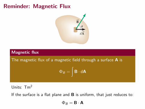
Magnetic flux
The magnetic flux of a magnetic field through a surface A is
ΦB =
∫B · dA
Units: Tm2
If the surface is a flat plane and B is uniform, that just reduces to:
ΦB = B · A

Changing flux and emf
When a magnet is at rest near a loop of wire there is no potentialdifference across the ends of the wire.
936 Chapter 31 Faraday’s Law
is moved either toward or away from it, the reading changes from zero. From these observations, we conclude that the loop detects that the magnet is moving relative to it and we relate this detection to a change in magnetic field. Therefore, it seems that a relationship exists between a current and a changing magnetic field. These results are quite remarkable because a current is set up even though no batteries are present in the circuit! We call such a current an induced current and say that it is produced by an induced emf. Now let’s describe an experiment conducted by Faraday and illustrated in Figure 31.2. A primary coil is wrapped around an iron ring and connected to a switch and a battery. A current in the coil produces a magnetic field when the switch is closed. A secondary coil also is wrapped around the ring and is connected to a sensitive ammeter. No battery is present in the secondary circuit, and the secondary coil is not electrically connected to the primary coil. Any current detected in the second-ary circuit must be induced by some external agent. Initially, you might guess that no current is ever detected in the secondary cir-cuit. Something quite amazing happens when the switch in the primary circuit is either opened or thrown closed, however. At the instant the switch is closed, the ammeter reading changes from zero momentarily and then returns to zero. At the instant the switch is opened, the ammeter changes to a reading with the opposite sign and again returns to zero. Finally, the ammeter reads zero when there is either a steady current or no current in the primary circuit. To understand what happens in this experiment, note that when the switch is closed, the current in the primary circuit produces a magnetic field that penetrates the secondary circuit. Further-more, when the switch is thrown closed, the magnetic field produced by the cur-rent in the primary circuit changes from zero to some value over some finite time, and this changing field induces a current in the secondary circuit. Notice that no current is induced in the secondary coil even when a steady current exists in the primary coil. It is a change in the current in the primary coil that induces a current in the secondary coil, not just the existence of a current. As a result of these observations, Faraday concluded that an electric current can be induced in a loop by a changing magnetic field. The induced current exists only while the magnetic field through the loop is changing. Once the magnetic field reaches a steady value, the current in the loop disappears. In effect, the loop behaves as though a source of emf were connected to it for a short time. It is cus-tomary to say that an induced emf is produced in the loop by the changing mag-netic field.
Michael FaradayBritish Physicist and Chemist (1791–1867)Faraday is often regarded as the great-est experimental scientist of the 1800s. His many contributions to the study of electricity include the invention of the electric motor, electric generator, and transformer as well as the discovery of electromagnetic induction and the laws of electrolysis. Greatly influenced by religion, he refused to work on the development of poison gas for the Brit-ish military.
© iS
tock
phot
o.co
m/S
teve
n W
ynn
Phot
ogra
phy
IN S
When a magnet is moved toward a loop of wire connected to a sensitive ammeter, the ammeter shows that a current is induced in the loop.
N S
When the magnet is held stationary, there is no induced current in the loop, even when the magnet is inside the loop.
a b
I
N S
c
When the magnet is moved away from the loop, the ammeter shows that the induced current is opposite that shown in part .a
Figure 31.1 A simple experiment showing that a current is induced in a loop when a magnet is moved toward or away from the loop.

Changing flux and emfWhen the north pole of the magnet is moved towards the loop, themagnetic flux increases.
936 Chapter 31 Faraday’s Law
is moved either toward or away from it, the reading changes from zero. From these observations, we conclude that the loop detects that the magnet is moving relative to it and we relate this detection to a change in magnetic field. Therefore, it seems that a relationship exists between a current and a changing magnetic field. These results are quite remarkable because a current is set up even though no batteries are present in the circuit! We call such a current an induced current and say that it is produced by an induced emf. Now let’s describe an experiment conducted by Faraday and illustrated in Figure 31.2. A primary coil is wrapped around an iron ring and connected to a switch and a battery. A current in the coil produces a magnetic field when the switch is closed. A secondary coil also is wrapped around the ring and is connected to a sensitive ammeter. No battery is present in the secondary circuit, and the secondary coil is not electrically connected to the primary coil. Any current detected in the second-ary circuit must be induced by some external agent. Initially, you might guess that no current is ever detected in the secondary cir-cuit. Something quite amazing happens when the switch in the primary circuit is either opened or thrown closed, however. At the instant the switch is closed, the ammeter reading changes from zero momentarily and then returns to zero. At the instant the switch is opened, the ammeter changes to a reading with the opposite sign and again returns to zero. Finally, the ammeter reads zero when there is either a steady current or no current in the primary circuit. To understand what happens in this experiment, note that when the switch is closed, the current in the primary circuit produces a magnetic field that penetrates the secondary circuit. Further-more, when the switch is thrown closed, the magnetic field produced by the cur-rent in the primary circuit changes from zero to some value over some finite time, and this changing field induces a current in the secondary circuit. Notice that no current is induced in the secondary coil even when a steady current exists in the primary coil. It is a change in the current in the primary coil that induces a current in the secondary coil, not just the existence of a current. As a result of these observations, Faraday concluded that an electric current can be induced in a loop by a changing magnetic field. The induced current exists only while the magnetic field through the loop is changing. Once the magnetic field reaches a steady value, the current in the loop disappears. In effect, the loop behaves as though a source of emf were connected to it for a short time. It is cus-tomary to say that an induced emf is produced in the loop by the changing mag-netic field.
Michael FaradayBritish Physicist and Chemist (1791–1867)Faraday is often regarded as the great-est experimental scientist of the 1800s. His many contributions to the study of electricity include the invention of the electric motor, electric generator, and transformer as well as the discovery of electromagnetic induction and the laws of electrolysis. Greatly influenced by religion, he refused to work on the development of poison gas for the Brit-ish military.
© iS
tock
phot
o.co
m/S
teve
n W
ynn
Phot
ogra
phy
IN S
When a magnet is moved toward a loop of wire connected to a sensitive ammeter, the ammeter shows that a current is induced in the loop.
N S
When the magnet is held stationary, there is no induced current in the loop, even when the magnet is inside the loop.
a b
I
N S
c
When the magnet is moved away from the loop, the ammeter shows that the induced current is opposite that shown in part .a
Figure 31.1 A simple experiment showing that a current is induced in a loop when a magnet is moved toward or away from the loop.
A current flows clockwise in the loop.(Magnetic moment of current loop point to the right.)

Changing flux and emfWhen the north pole of the magnet is moved away from the loop,the magnetic flux decreases.
936 Chapter 31 Faraday’s Law
is moved either toward or away from it, the reading changes from zero. From these observations, we conclude that the loop detects that the magnet is moving relative to it and we relate this detection to a change in magnetic field. Therefore, it seems that a relationship exists between a current and a changing magnetic field. These results are quite remarkable because a current is set up even though no batteries are present in the circuit! We call such a current an induced current and say that it is produced by an induced emf. Now let’s describe an experiment conducted by Faraday and illustrated in Figure 31.2. A primary coil is wrapped around an iron ring and connected to a switch and a battery. A current in the coil produces a magnetic field when the switch is closed. A secondary coil also is wrapped around the ring and is connected to a sensitive ammeter. No battery is present in the secondary circuit, and the secondary coil is not electrically connected to the primary coil. Any current detected in the second-ary circuit must be induced by some external agent. Initially, you might guess that no current is ever detected in the secondary cir-cuit. Something quite amazing happens when the switch in the primary circuit is either opened or thrown closed, however. At the instant the switch is closed, the ammeter reading changes from zero momentarily and then returns to zero. At the instant the switch is opened, the ammeter changes to a reading with the opposite sign and again returns to zero. Finally, the ammeter reads zero when there is either a steady current or no current in the primary circuit. To understand what happens in this experiment, note that when the switch is closed, the current in the primary circuit produces a magnetic field that penetrates the secondary circuit. Further-more, when the switch is thrown closed, the magnetic field produced by the cur-rent in the primary circuit changes from zero to some value over some finite time, and this changing field induces a current in the secondary circuit. Notice that no current is induced in the secondary coil even when a steady current exists in the primary coil. It is a change in the current in the primary coil that induces a current in the secondary coil, not just the existence of a current. As a result of these observations, Faraday concluded that an electric current can be induced in a loop by a changing magnetic field. The induced current exists only while the magnetic field through the loop is changing. Once the magnetic field reaches a steady value, the current in the loop disappears. In effect, the loop behaves as though a source of emf were connected to it for a short time. It is cus-tomary to say that an induced emf is produced in the loop by the changing mag-netic field.
Michael FaradayBritish Physicist and Chemist (1791–1867)Faraday is often regarded as the great-est experimental scientist of the 1800s. His many contributions to the study of electricity include the invention of the electric motor, electric generator, and transformer as well as the discovery of electromagnetic induction and the laws of electrolysis. Greatly influenced by religion, he refused to work on the development of poison gas for the Brit-ish military.
© iS
tock
phot
o.co
m/S
teve
n W
ynn
Phot
ogra
phy
IN S
When a magnet is moved toward a loop of wire connected to a sensitive ammeter, the ammeter shows that a current is induced in the loop.
N S
When the magnet is held stationary, there is no induced current in the loop, even when the magnet is inside the loop.
a b
I
N S
c
When the magnet is moved away from the loop, the ammeter shows that the induced current is opposite that shown in part .a
Figure 31.1 A simple experiment showing that a current is induced in a loop when a magnet is moved toward or away from the loop.
A current flows counterclockwise in the loop.(Magnetic moment of current loop point to the left.)

Faraday’s Law
Faraday’s Law
If a conducting loop experiences a changing magnetic flux throughthe area of the loop, an emf EF is induced in the loop that isdirectly proportional to the rate of change of the flux, ΦB withtime.
Faraday’s Law for a conducting loop:
EF = −dΦB
dt
Note: If there is a changing flux, there will be an induced emf,however, if dΦB
dt = 0 there could still be emf in a wire from othereffects. (Enet = EF + Eother)

Faraday’s Law
Faraday’s Law
If a conducting loop experiences a changing magnetic flux throughthe area of the loop, an emf EF is induced in the loop that isdirectly proportional to the rate of change of the flux, ΦB withtime.
Faraday’s Law for a conducting loop:
EF = −dΦB
dt
Note: If there is a changing flux, there will be an induced emf,however, if dΦB
dt = 0 there could still be emf in a wire from othereffects. (Enet = EF + Eother)
Faraday’s Law
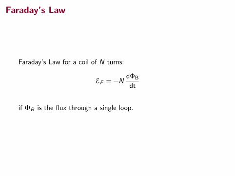
Faraday’s Law for a coil of N turns:
EF = −NdΦB
dt
if ΦB is the flux through a single loop.

Changing Magnetic Flux
The magnetic flux might change for any of several reasons:
• the magnitude of B can change with time,
• the area A enclosed by the loop can change with time, or
• the angle θ between the field and the normal to the loop canchange with time.

Lenz’s Law
794 CHAPTE R 30 I N DUCTION AN D I N DUCTANCE
30-4 Lenz’s LawSoon after Faraday proposed his law of induction, Heinrich Friedrich Lenzdevised a rule for determining the direction of an induced current in a loop:
Additional examples, video, and practice available at WileyPLUS
Fig. 30-3 A coil C is located inside a solenoid S, which carries current i.
Axis
i
i
C
S
An induced current has a direction such that the magnetic field due to the currentopposes the change in the magnetic flux that induces the current.
Fig. 30-4 Lenz’s law at work.As themagnet is moved toward the loop, a currentis induced in the loop.The current producesits own magnetic field, with magnetic di-pole moment oriented so as to opposethe motion of the magnet.Thus, the in-duced current must be counterclockwise as shown.
!:
N
S
i
N
S
µ µ
The magnet's motioncreates a magneticdipole that opposesthe motion.
Furthermore, the direction of an induced emf is that of the induced current. To geta feel for Lenz’s law, let us apply it in two different but equivalent ways to Fig. 30-4,where the north pole of a magnet is being moved toward a conducting loop.
1. Opposition to Pole Movement. The approach of the magnet’s north pole inFig. 30-4 increases the magnetic flux through the loop and thereby induces acurrent in the loop. From Fig. 29-21, we know that the loop then acts as a mag-netic dipole with a south pole and a north pole, and that its magnetic dipolemoment is directed from south to north. To oppose the magnetic fluxincrease being caused by the approaching magnet, the loop’s north pole (andthus ) must face toward the approaching north pole so as to repel it (Fig.30-4). Then the curled–straight right-hand rule for (Fig. 29-21) tells us thatthe current induced in the loop must be counterclockwise in Fig. 30-4.
If we next pull the magnet away from the loop, a current will again beinduced in the loop. Now, however, the loop will have a south pole facingthe retreating north pole of the magnet, so as to oppose the retreat. Thus, theinduced current will be clockwise.
2. Opposition to Flux Change. In Fig. 30-4, with the magnet initially distant, nomagnetic flux passes through the loop. As the north pole of the magnet then
!:!:
!:
because the final current in the solenoid is zero. To find theinitial flux "B,i, we note that area A is pd2 (# 3.464 $ 10%41
4
4. The flux through each turn of coil C depends on the areaA and orientation of that turn in the solenoid’s magneticfield . Because is uniform and directed perpendicularto area A, the flux is given by Eq. 30-2 ("B # BA).
5. The magnitude B of the magnetic field in the interior of a so-lenoid depends on the solenoid’s current i and its number nof turns per unit length,according to Eq.29-23 (B # m0in).
Calculations: Because coil C consists of more than oneturn, we apply Faraday’s law in the form of Eq. 30-5(! # %N d"B/dt), where the number of turns N is 130 andd"B/dt is the rate at which the flux changes.
Because the current in the solenoid decreases at asteady rate, flux "B also decreases at a steady rate, and so wecan write d"B/dt as &"B/&t. Then, to evaluate &"B, we needthe final and initial flux values. The final flux "B, f is zero
B:B
:
m2) and the number n is 220 turns/cm, or 22 000 turns/m.Substituting Eq. 29-23 into Eq. 30-2 then leads to
Now we can write
We are interested only in magnitudes; so we ignore the mi-nus signs here and in Eq. 30-5, writing
(Answer)# 7.5 $ 10 %2 V # 75 mV.
! # N d"B
dt# (130 turns)(5.76 $ 10 %4 V)
# %5.76 $ 10 %4 Wb/s # %5.76 $ 10 %4 V.
#(0 % 1.44 $ 10 %5 Wb)
25 $ 10 %3 s
d"B
dt#
&"B
&t #
"B, f % "B,i
&t
# 1.44 $ 10 %5 Wb. $ (3.464 $ 10 %4 m2)
# (4' $ 10 %7 T (m/A)(1.5 A)(22 000 turns/m)
"B, i # BA # (!0 in)A
halliday_c30_791-825hr.qxd 11-12-2009 12:19 Page 794
Lenz’s Law
An induced current has a direction such that themagnetic field due to the current opposes thechange in the magnetic flux that induces thecurrent.
Basically, Lenz’s law let’s us interpret the minussign in the equation we write to representFaraday’s Law.
E = −−−dΦB
dt
1Figure from Halliday, Resnick, Walker, 9th ed.

Faraday’s and Lenz’s Laws
What about this case? We found the current should flowcounterclockwise.
31.3 Lenz’s Law 945
produce a field directed out of the page. Hence, the induced current must be directed counterclockwise when the bar moves to the right. (Use the right-hand rule to verify this direction.) If the bar is moving to the left as in Figure 31.11b, the external magnetic flux through the area enclosed by the loop decreases with time. Because the field is directed into the page, the direction of the induced current must be clockwise if it is to produce a field that also is directed into the page. In either case, the induced current attempts to maintain the original flux through the area enclosed by the current loop. Let’s examine this situation using energy considerations. Suppose the bar is given a slight push to the right. In the preceding analysis, we found that this motion sets up a counterclockwise current in the loop. What happens if we assume the cur-rent is clockwise such that the direction of the magnetic force exerted on the bar is to the right? This force would accelerate the rod and increase its velocity, which in turn would cause the area enclosed by the loop to increase more rapidly. The result would be an increase in the induced current, which would cause an increase in the force, which would produce an increase in the current, and so on. In effect, the sys-tem would acquire energy with no input of energy. This behavior is clearly inconsis-tent with all experience and violates the law of conservation of energy. Therefore, the current must be counterclockwise.
Q uick Quiz 31.3 Figure 31.12 shows a circular loop of wire falling toward a wire carrying a current to the left. What is the direction of the induced current in the loop of wire? (a) clockwise (b) counterclockwise (c) zero (d) impossible to determine
BinS
vSI
R
a b
IR
vS
As the conducting bar slides to the right, the magnetic flux due to the external magnetic field into the page through the area enclosed by the loop increases in time.
BinS
By Lenz’s law, the induced current must be counterclockwise to produce a counteracting magnetic field directed out of the page.
Figure 31.11 (a) Lenz’s law can be used to determine the direction of the induced current. (b) When the bar moves to the left, the induced current must be clockwise. Why?
I
vS
Figure 31.12 (Quick Quiz 31.3)
Conceptual Example 31.5 Application of Lenz’s Law
A magnet is placed near a metal loop as shown in Figure 31.13a (page 946).
(A) Find the direction of the induced current in the loop when the magnet is pushed toward the loop.
As the magnet moves to the right toward the loop, the external magnetic flux through the loop increases with time. To counteract this increase in flux due to a field toward the right, the induced current produces its own magnetic field to the left as illustrated in Figure 31.13b; hence, the induced current is in the direction shown. Knowing that like
S O L U T I O N
continued
The flux from the wire is into the page and increasing.
The field from the current in the loop is out of the page.
There is an upward resistive force on the ring. (cf. HW3, #3.)

Loops in B-Fields Question
The figure shows four wire loops, with edge lengths of either L or2L. All four loops will move through a region of uniform magneticfield B (directed out of the page) at the same constant velocity.
Rank the four loops according to the maximum magnitude of theemf induced as they move into the field, greatest first.
800 CHAPTE R 30 I N DUCTION AN D I N DUCTANCE
Eddy CurrentsSuppose we replace the conducting loop of Fig. 30-8 with a solid conducting plate.If we then move the plate out of the magnetic field as we did the loop (Fig. 30-10a),the relative motion of the field and the conductor again induces a current in theconductor. Thus, we again encounter an opposing force and must do work becauseof the induced current. With the plate, however, the conduction electrons makingup the induced current do not follow one path as they do with the loop. Instead, theelectrons swirl about within the plate as if they were caught in an eddy (whirlpool)of water. Such a current is called an eddy current and can be represented, as it is inFig. 30-10a, as if it followed a single path.
As with the conducting loop of Fig. 30-8, the current induced in the plateresults in mechanical energy being dissipated as thermal energy. The dissipationis more apparent in the arrangement of Fig. 30-10b; a conducting plate, free torotate about a pivot, is allowed to swing down through a magnetic field likea pendulum. Each time the plate enters and leaves the field, a portion of itsmechanical energy is transferred to its thermal energy. After several swings, nomechanical energy remains and the warmed-up plate just hangs from its pivot.
CHECKPOINT 3
The figure shows four wire loops, with edge lengths of either L or 2L. All four loopswill move through a region of uniform magnetic field (directed out of the page) atthe same constant velocity. Rank the four loops according to the maximum magnitudeof the emf induced as they move through the field, greatest first.
B:
a b
c d
B
30-6 Induced Electric FieldsLet us place a copper ring of radius r in a uniform external magnetic field, as inFig. 30-11a.The field—neglecting fringing—fills a cylindrical volume of radius R.Suppose that we increase the strength of this field at a steady rate, perhaps byincreasing—in an appropriate way—the current in the windings of the electro-magnet that produces the field. The magnetic flux through the ring will thenchange at a steady rate and—by Faraday’s law—an induced emf and thus aninduced current will appear in the ring. From Lenz’s law we can deduce that thedirection of the induced current is counterclockwise in Fig. 30-11a.
If there is a current in the copper ring, an electric field must be present along thering because an electric field is needed to do the work of moving the conductionelectrons. Moreover, the electric field must have been produced by the changing
Fig. 30-10 (a) As you pull a solid con-ducting plate out of a magnetic field, eddycurrents are induced in the plate.A typicalloop of eddy current is shown. (b) A con-ducting plate is allowed to swing like a pen-dulum about a pivot and into a region ofmagnetic field.As it enters and leaves thefield, eddy currents are induced in theplate.
Eddy current loop
Pivot
(a) (b)
B
B
halliday_c30_791-825hr.qxd 11-12-2009 12:19 Page 800
A a, b, c, d
B (b and c), (a and d)
C (c and d), (a and b)
D (a and b), (c and d)
1Halliday, Resnick, Walker, page

Loops in B-Fields Question
The figure shows four wire loops, with edge lengths of either L or2L. All four loops will move through a region of uniform magneticfield B (directed out of the page) at the same constant velocity.
Rank the four loops according to the maximum magnitude of theemf induced as they move into the field, greatest first.
800 CHAPTE R 30 I N DUCTION AN D I N DUCTANCE
Eddy CurrentsSuppose we replace the conducting loop of Fig. 30-8 with a solid conducting plate.If we then move the plate out of the magnetic field as we did the loop (Fig. 30-10a),the relative motion of the field and the conductor again induces a current in theconductor. Thus, we again encounter an opposing force and must do work becauseof the induced current. With the plate, however, the conduction electrons makingup the induced current do not follow one path as they do with the loop. Instead, theelectrons swirl about within the plate as if they were caught in an eddy (whirlpool)of water. Such a current is called an eddy current and can be represented, as it is inFig. 30-10a, as if it followed a single path.
As with the conducting loop of Fig. 30-8, the current induced in the plateresults in mechanical energy being dissipated as thermal energy. The dissipationis more apparent in the arrangement of Fig. 30-10b; a conducting plate, free torotate about a pivot, is allowed to swing down through a magnetic field likea pendulum. Each time the plate enters and leaves the field, a portion of itsmechanical energy is transferred to its thermal energy. After several swings, nomechanical energy remains and the warmed-up plate just hangs from its pivot.
CHECKPOINT 3
The figure shows four wire loops, with edge lengths of either L or 2L. All four loopswill move through a region of uniform magnetic field (directed out of the page) atthe same constant velocity. Rank the four loops according to the maximum magnitudeof the emf induced as they move through the field, greatest first.
B:
a b
c d
B
30-6 Induced Electric FieldsLet us place a copper ring of radius r in a uniform external magnetic field, as inFig. 30-11a.The field—neglecting fringing—fills a cylindrical volume of radius R.Suppose that we increase the strength of this field at a steady rate, perhaps byincreasing—in an appropriate way—the current in the windings of the electro-magnet that produces the field. The magnetic flux through the ring will thenchange at a steady rate and—by Faraday’s law—an induced emf and thus aninduced current will appear in the ring. From Lenz’s law we can deduce that thedirection of the induced current is counterclockwise in Fig. 30-11a.
If there is a current in the copper ring, an electric field must be present along thering because an electric field is needed to do the work of moving the conductionelectrons. Moreover, the electric field must have been produced by the changing
Fig. 30-10 (a) As you pull a solid con-ducting plate out of a magnetic field, eddycurrents are induced in the plate.A typicalloop of eddy current is shown. (b) A con-ducting plate is allowed to swing like a pen-dulum about a pivot and into a region ofmagnetic field.As it enters and leaves thefield, eddy currents are induced in theplate.
Eddy current loop
Pivot
(a) (b)
B
B
halliday_c30_791-825hr.qxd 11-12-2009 12:19 Page 800
A a, b, c, d
B (b and c), (a and d)
C (c and d), (a and b)←D (a and b), (c and d)
1Halliday, Resnick, Walker, page

Summary
• motional emf
• Faraday’s law
• Lenz’s law
• applications
Next Test this Friday, Mar 9.
HomeworkSerway & Jewett:
• NEW: Ch 31, Obj. Qs: 1, 3, 5, 7; Conc. Qs: 3, 5; Problems:1, 5, 9, 13, 21, 27, 31, 33 (hint: use the Lorentz force on theelectrons in the spinning disk)