configuration guide for vmware™ esx server host … . xi. configuration guide for vmware™ esx...
TRANSCRIPT

Configuration Guide for VMware™ ESX Server Host Attachment
Hitachi Virtual Storage Platform Hitachi Universal Storage Platform V/VM
Hitachi TagmaStore® Universal Storage Platform Hitachi TagmaStore® Network Storage Controller
FASTFIND LINK
S
Document Organization
Product Version
Getting Help
Contents
MK-98RD6716-03

ii
Configuration Guide for VMware™ ESX Server Host Attachment
Copyright © 2011 Hitachi, Ltd. All rights reserved.
No part of this publication may be reproduced or transmitted in any form or by any means, electronic or mechanical, including photocopying and recording, or stored in a database or retrieval system for any purpose without the express written permission of Hitachi, Ltd. (hereinafter referred to as “Hitachi”) and Hitachi Data Systems Corporation (hereinafter referred to as “Hitachi Data Systems”).
Hitachi Data Systems reserves the right to make changes to this document at any time without notice and assumes no responsibility for its use. This document contains the most current information available at the time of publication. When new or revised information becomes available, this entire document will be updated and distributed to all registered users.
All of the features described in this document may not be currently available. Refer to the most recent product announcement or contact your local Hitachi Data Systems sales office for information about feature and product availability.
Notice: Hitachi Data Systems products and services can be ordered only under the terms and conditions of the applicable Hitachi Data Systems agreements. The use of Hitachi Data Systems products is governed by the terms of your agreements with Hitachi Data Systems.
Hitachi is a registered trademark of Hitachi, Ltd. in the United States and other countries. Hitachi Data Systems is a registered trademark and service mark of Hitachi, Ltd. in the United States and other countries.
All other trademarks, service marks, and company names are properties of their respective owners.
Microsoft product screen shots reprinted with permission from Microsoft Corporation.
Contents iii
Configuration Guide for VMware™ ESX Server Host Attachment
Contents
Preface................................................................................................... v
Intended Audience .............................................................................................. vi Product Version................................................................................................... vi Document Revision Level ..................................................................................... vi Source Documents for this Revision ...................................................................... vi Changes in this Revision ..................................................................................... vii Referenced Documents....................................................................................... vii Document Organization ..................................................................................... viii Document Conventions...................................................................................... viii Convention for Storage Capacity Values .................................................................x Accessing Product Documentation .........................................................................x Getting Help ....................................................................................................... xi Comments .......................................................................................................... xi
Overview ............................................................................................. 1-1
About the Hitachi RAID Storage Systems.............................................................1-2 About the VMware ESX Platform.........................................................................1-3 Installation and Configuration Roadmap..............................................................1-4
Hardware Installation............................................................................ 2-1
Installation and Configuration Requirements........................................................2-2 Hitachi RAID Storage System Requirements..................................................2-2 Storage Area Network Requirements ............................................................2-2 VMware Host Server Requirements ..............................................................2-2 Host Bus Adapter Requirements...................................................................2-3
Installing the Hitachi RAID Storage System .........................................................2-4
Hitachi RAID Storage System Configuration ............................................ 3-1
Configuring the Hitachi RAID Storage System......................................................3-2

iv Contents
Configuration Guide for VMware™ ESX Server Host Attachment
Setting the Host Mode................................................................................ 3-2 Setting the Host Mode Options.................................................................... 3-3 Setting the System Option Modes................................................................ 3-4 Configuring the Fibre-Channel Ports ............................................................ 3-5
Configuring the Fibre-Channel HBAs................................................................... 3-6 Setting the Queue Depth Parameter ............................................................ 3-7
Setting the Queue Depth on QLogic HBAs ............................................. 3-7 Setting the Queue Depth on Emulex HBAs............................................. 3-8
Configuring the HBA BIOS .......................................................................... 3-9 Configuring the QLogic HBA BIOS......................................................... 3-9 Configuring the Emulex HBA BIOS ...................................................... 3-10
Connecting the Storage System to the VMware Server....................................... 3-11 Storage Provisioning ....................................................................................... 3-12
Creating a VMFS and Attaching Raw Devices .......................................... 4-1
Creating a Virtual Machine File System ............................................................... 4-2 Attaching a Raw Device .................................................................................. 4-10
Troubleshooting ................................................................................... 5-1
General Troubleshooting ................................................................................... 5-2 Calling the Hitachi Data Systems Support Center................................................. 5-4
Specifications for Device Types................................................................. 1
Using VMware with Hitachi RAID Storage Systems ..................................... 1
VMware ESX Server and VirtualCenter Compatibility ............................................... 2 Installing and Configuring VMware........................................................................ 3
Installing and Configuring VMware ESX Server ................................................ 3 Upgrading an ESX Server and VirtualCenter Environment ................................. 3
Creating and Managing VMware Infrastructure Components.................................... 4
Acronyms and Abbreviations

Preface v
Configuration Guide for VMware™ ESX Server Host Attachment
Preface
This document describes and provides instructions for installing and configuring the devices on the Hitachi RAID storage systems for operations in a VMware™ ESX Server environment. The Hitachi RAID storage system models include the Hitachi Virtual Storage Platform (VSP), Hitachi Universal Storage Platform V and VM (USP V/VM), and the Hitachi TagmaStore Universal Storage Platform and Network Storage Controller (USP/NSC).
Please read this document carefully to understand how to use this product, and maintain a copy for reference purposes.
This preface includes the following information:
Intended Audience
Product Version
Document Revision Level
Source Documents for this Revision
Changes in this Revision
Referenced Documents
Document Organization
Document Conventions
Convention for Storage Capacity Values
Accessing Product Documentation
Getting Help
Comments

vi Preface
Configuration Guide for VMware™ ESX Server Host Attachment
Intended Audience
This document is intended for system administrators, Hitachi Data Systems representatives, and authorized service providers who are involved in installing, configuring, and operating the Hitachi RAID storage systems.
Readers of this document should meet the following requirements:
• You should have a background in data processing and understand RAID storage systems and their basic functions.
• You should be familiar with the Hitachi RAID storage system(s), and you should have read the User and Reference Guide for the storage system.
• You should be familiar with the Storage Navigator software for the Hitachi RAID storage system(s), and you should have read the Storage Navigator User’s Guide.
• You should be familiar with the VMware ESX Server operating system and the hardware hosting the VMware ESX Server system.
• You should be familiar with the hardware used to attach the Hitachi RAID storage system to the VMware ESX Server host, including fibre-channel cabling, host bus adapters (HBAs), switches, and hubs.
Product Version
This document revision applies to the following microcode levels:
• Hitachi Virtual Storage Platform microcode 70-02-0x or later.
• Hitachi Universal Storage Platform V/VM microcode 60-03-2x or later.
• Hitachi TagmaStore USP/NSC microcode versions 50-09-3x or later.
Document Revision Level
Revision Date Description
MK-98RD6716-P August 2008 Preliminary Release
MK-98RD6716-00 October 2008 Initial release, supersedes and replaces MK-98RD6716-P
MK-98RD6716-01 July 2010 Revision 1, supersedes and replaces MK-98RD6716-00
MK-98RD6716-02 October 2010 Revision 2, supersedes and replaces MK-98RD6716-01
MK-98RD6716-03 April 2011 Revision 3, supersedes and replaces MK-98RD6716-02
Source Documents for this Revision • RSD-98RD6716-03a

Preface vii
Configuration Guide for VMware™ ESX Server Host Attachment
Changes in this Revision • Added new host mode option 54 for the VSP storage system (Table 3-1).
• Added information about vStorage API for Array Integration (VAAI) (VMware Host Server Requirements).
Referenced Documents
Hitachi Virtual Storage Platform documentation:
• Provisioning Guide for Open Systems, MK-90RD7022
• Storage Navigator User Guide, MK-90RD7027
• Storage Navigator Messages, MK-90RD7028
• User and Reference Guide, MK-90RD7042
Hitachi Universal Storage Platform V/VM documentation:
• LUN Manager User’s Guide, MK-96RD615
• LUN Expansion User’s Guide, MK-96RD616
• Storage Navigator User’s Guide, MK-96RD621
• Virtual LVI/LUN and Volume Shredder User’s Guide, MK-96RD630
• Storage Navigator Messages, MK-96RD633
• User and Reference Guide, MK-96RD635
Hitachi Universal Storage Platform and Network Storage Controller documentation:
• Storage Navigator Error Codes, MK-94RD202
• LUN Manager User’s Guide, MK-94RD203
• LUN Expansion and Virtual LVI/LUN User’s Guide, MK-94RD205
• Storage Navigator User’s Guide, MK-94RD206
• User and Reference Guide, MK-94RD231
VMware ESX Server user documentation: refer to www.VMware.com.

viii Preface
Configuration Guide for VMware™ ESX Server Host Attachment
Document Organization
The following table provides an overview of the contents and organization of this document. Click the chapter title in the left column to go to that chapter. The first page of each chapter provides links to the sections in that chapter.
Chapter Description
Chapter 1, Overview Provides a brief overview of the Hitachi RAID storage systems, the VMware ESX Server host, and the installation procedure.
Chapter 2, Hardware Installation
Provides instructions for installing and connecting the Hitachi RAID storage system to the VMware ESX Server host.
Chapter 3, Hitachi RAID Storage System Configuration
Describes how to configure the Hitachi RAID storage system for operation with the VMware host.
Chapter 4, Creating a VMFS and Attaching Raw Devices
Provides instructions for creating VMFS and attaching raw devices.
Chapter 5, Troubleshooting Provides troubleshooting information for VMware host attachment.
Appendix A, Specifications for Device Types
Provides specifications for the device emulation types in the Hitachi RAID storage systems.
Appendix B, Using VMware with Hitachi RAID Storage Systems
Contains reference information to help you implement VMware software with the Hitachi RAID storage systems.
Document Conventions
The terms “Virtual Storage Platform” and “VSP” refer to all models of the Hitachi Virtual Storage Platform storage system, unless otherwise noted.
The terms “Universal Storage Platform V” and “Universal Storage Platform VM” refer to all models of the Hitachi Universal Storage Platform V/VM storage systems, unless otherwise noted.
The terms “TagmaStore Universal Storage Platform” and “TagmaStore Network Storage Controller” refer to all models of the Hitachi TagmaStore USP/NSC storage systems, unless otherwise noted.

This document uses the following typographic conventions:
Convention Description
Bold Indicates text on a window, other than the window title, including menus, menu options, buttons, fields, and labels. Example: Click OK.
Italic Indicates a variable, which is a placeholder for actual text provided by the user or system. Example: copy source-file target-file
Note: Angled brackets (< >) are also used to indicate variables.
screen/code Indicates text that is displayed on screen or entered by the user. Example: # pairdisplay -g oradb
< > angled brackets Indicates a variable, which is a placeholder for actual text provided by the user or system. Example: # pairdisplay -g <group>
Note: Italic font is also used to indicate variables.
[ ] square brackets Indicates optional values. Example: [ a | b ] indicates that you can choose a, b, or nothing.
{ } braces Indicates required or expected values. Example: { a | b } indicates that you must choose either a or b.
| vertical bar Indicates that you have a choice between two or more options or arguments. Examples:
[ a | b ] indicates that you can choose a, b, or nothing.
{ a | b } indicates that you must choose either a or b.
This document uses the following icons to draw attention to information:
Icon Meaning Description
Note Calls attention to important or additional information.
Tip Provides helpful information, guidelines, or suggestions for performing tasks more effectively.
Caution Warns the user of adverse conditions or consequences (e.g., disruptive operations).
WARNING Warns the user of severe conditions or consequences (e.g., destructive operations).
Preface ix
Configuration Guide for VMware™ ESX Server Host Attachment

x Preface
Configuration Guide for VMware™ ESX Server Host Attachment
Convention for Storage Capacity Values
Physical storage capacity values (e.g., disk drive capacity) are calculated based on the following values:
Physical capacity unit Value
1 KB 1,000 (103) bytes
1 MB 1,000 KB or 1,0002 bytes
1 GB 1,000 MB or 1,0003 bytes
1 TB 1,000 GB or 1,0004 bytes
1 PB 1,000 TB or 1,0005 bytes
1 EB 1,000 PB or 1,0006 bytes
Logical storage capacity values (e.g., logical device capacity) are calculated based on the following values:
Logical capacity unit Value
1 block 512 bytes
1 KB 1,024 (210) bytes
1 MB 1,024 KB or 1,0242 bytes
1 GB 1,024 MB or 1,0243 bytes
1 TB 1,024 GB or 1,0244 bytes
1 PB 1,024 TB or 1,0245 bytes
1 EB 1,024 PB or 1,0246 bytes
Accessing Product Documentation
The user documentation for the Hitachi RAID storage systems is available on the Hitachi Data Systems Portal: https://hdssupport.hds.com. Check this site for the most current documentation, including important updates that may have been made after the release of the product.

Preface xi
Configuration Guide for VMware™ ESX Server Host Attachment
Getting Help
The Hitachi Data Systems customer support staff is available 24 hours a day, seven days a week. If you need technical support, log on to the Hitachi Data Systems Portal for contact information: https://hdssupport.hds.com
Comments
Please send us your comments on this document: [email protected]. Include the document title, number, and revision, and refer to specific sections and paragraphs whenever possible.
Thank you! (All comments become the property of Hitachi Data Systems.)

xii Preface
Configuration Guide for VMware™ ESX Server Host Attachment
1
Overview 1-1
Configuration Guide for VMware™ ESX Server Host Attachment
Overview
This chapter provides an overview of the Hitachi RAID storage systems, the VMware host platform, and the installation and configuration activities:
About the Hitachi RAID Storage Systems
About the VMware ESX Platform
Installation and Configuration Roadmap

1-2 Overview
Configuration Guide for VMware™ ESX Server Host Attachment
About the Hitachi RAID Storage Systems
The Hitachi RAID storage systems offer a wide range of storage and data services, including thin provisioning with Hitachi Dynamic Provisioning™ software, application-centric storage management and logical partitioning, and simplified and unified data replication across heterogeneous storage systems. These storage systems are an integral part of the Services-Oriented Storage Solutions architecture from Hitachi Data Systems, providing the foundation for matching application requirements to different classes of storage and delivering critical services such as:
• Business continuity services
• Content management services (search, indexing)
• Non-disruptive data migration
• Volume management across heterogeneous storage arrays
• Thin provisioning
• Security services (immutability, logging, auditing, data shredding)
• Data de-duplication
• I/O load balancing
• Data classification
• File management services
The Hitachi RAID storage systems include the Virtual Storage Platform (VSP), Universal Storage Platform V and VM (USP V/VM), and the TagmaStore Universal Storage Platform and Network Storage Controller (USP/NSC). These storage systems provide heterogeneous connectivity to support multiple concurrent attachment to a variety of host operating systems (OS), including VMware® as well as Windows®, UNIX®, Linux®, and mainframe servers, enabling massive consolidation and storage aggregation across disparate platforms. The storage systems can operate with multi-host applications and host clusters, and are designed to handle very large databases as well as data warehousing and data mining applications that store and retrieve terabytes of data.
The Hitachi RAID storage systems are configured with OPEN-V logical units (LUs) and are compatible with most fibre-channel (FC) host bus adapters (HBAs). Users can perform additional LU configuration activities using the LUN Manager, Virtual LVI/LUN (VLL), and LUN Expansion (LUSE) features provided by the Storage Navigator software, which is the primary user interface for the storage systems.
For more information about storage solutions and the Hitachi RAID storage systems, please contact your Hitachi Data Systems account team.

Overview 1-3
Configuration Guide for VMware™ ESX Server Host Attachment
About the VMware ESX Platform
The VMware ESX Server product is a “bare-metal” hypervisor that partitions physical servers in multiple virtual machines. Each virtual machine represents a complete system, with processors, memory, networking, storage and BIOS. VMware ESX enables multiple virtual machines to share physical resources, run unmodified operating systems and applications, and run the most resource-intensive applications side-by-side on the same server.
For more information about the VMware ESX Server host platform, please refer to the VMware user documentation, or contact VMware technical support.

1-4 Overview
Configuration Guide for VMware™ ESX Server Host Attachment
Installation and Configuration Roadmap
Table 1-1 shows the activities that are performed to connect the Hitachi RAID storage system to the VMware ESX Server host and configure the new logical devices (LDEVs) on the storage system for operations with the VMware host. Some activities are performed by the Hitachi Data Systems representative, while other activities are performed by the user:
• The Hitachi Data Systems representative performs the physical installation of the Hitachi RAID storage system and connection to the host.
• The user prepares for the installation and configures the new devices, with assistance from the Hitachi Data Systems representative.
Table 1-1 Installation and Configuration Roadmap
Task
1. Verify that the installation and configuration requirements have been met.
2. Prepare the Hitachi RAID storage system, VMware host, and HBAs for the installation.
4. Connect the Hitachi RAID storage system to the VMware ESX Server host.
5. Configure the new devices for operation with the VMware host.
6. Create and manage the VMware infrastructure components.

2
Hardware Installation 2-1
Configuration Guide for VMware™ ESX Server Host Attachment
Hardware Installation
This chapter describes preparation for hardware installation:
Installation and Configuration Requirements
Installing the Hitachi RAID Storage System

2-2 Hardware Installation
Configuration Guide for VMware™ ESX Server Host Attachment
Installation and Configuration Requirements
Hitachi RAID Storage System Requirements
The Hitachi Storage Navigator software must be installed and operational. The Hitachi LUN Manager software on Storage Navigator must also be installed and operational. For details, see the Storage Navigator User’s Guide for the storage system.
For information about supported fibre-channel adapters, cables, hubs, and switches, refer to the Hitachi Data Systems interoperability site: http://www.hds.com/products/interoperability
Storage Area Network Requirements
A storage area network (SAN) is required for connecting the Hitachi RAID storage system to the VMware ESX Server host. VMware does not support FC-AL and direct-connect connections to storage systems.
For information about supported fibre-channel switches, topology, and firmware versions for SAN configurations, see the Hitachi Data Systems interoperability site: http://www.hds.com/products/interoperability
VMware Host Server Requirements
Verify that you have reviewed the latest hardware, system, and software requirements for attaching new storage to the Vmware ESX Server host. Refer to the VMware ESX Server user documentation for information:
http://www.VMware.com/support.
Verify that the OS version, architecture, relevant patches, and maintenance levels are supported by Hitachi Data Systems. Refer to the Hitachi Data Systems interoperability site for information about supported versions: http://www.hds.com/products/interoperability
Verify that you have the VMware ESX Server software installation media.
The Hitachi VSP supports VMware vStorage API for Array Integration (VAAI). VAAI enables the offload of specific storage operations from the VMware ESX host to the VSP for improved performance and efficiency. These APIs, available in VMware’s vSphere 4.1, provide integration with the advanced features and capabilities of the Hitachi VSP such as thin provisioning, dynamic tiering, and storage virtualization. For more information, see the following sites:
www.hds.com/go/vmware/
www.vmware.com/products/vstorage-apis-for-array-integration/
Hardware Installation 2-3
Configuration Guide for VMware™ ESX Server Host Attachment
Host Bus Adapter Requirements
Verify that the HBAs that will be connected to the Hitachi RAID storage system and the associated drivers and BIOS are supported by the Hitachi RAID storage system. For information about supported HBAs and drivers, refer to the Hitachi Data Systems interoperability site: http://www.hds.com/products/interoperability/
For HBA installation information, check the documentation or website of the HBA vendor. Verify that the HBAs are functioning properly.

2-4 Hardware Installation
Configuration Guide for VMware™ ESX Server Host Attachment
Installing the Hitachi RAID Storage System
The Hitachi RAID storage systems come with all the hardware and cabling required for installation. The Hitachi Data Systems representative follows the instructions and precautions in the Maintenance Manual for the storage system for installing the product. The installation tasks include:
• Checking all specifications to ensure proper installation and configuration.
• Assembling all hardware and cabling.
• Verifying that the Storage Navigator software has been installed and is ready for use. For more information, refer to the Storage Navigator User’s Guide for the storage system.
• Installing and formatting the logical devices (LDEVs). Be sure to get the desired LDEV configuration information from the user, including the desired number of OPEN-V, LUSE, VLL, and VLL LUSE devices. For further information:
– Hitachi VSP: see the Provisioning Guide for Open Systems.
– Hitachi USP V/VM, USP/NSC: see the LUN Manager User’s Guide, LUN Expansion User’s Guide, and Virtual LVI/LUN User’s Guide.
Table 2-1 describes the types of logical devices that can be configured on the Hitachi RAID storage systems for operation with the VMware host system. For detailed specifications on the device emulation types, see Appendix A.
• Installing the fibre-channel HBAs and cabling. The total fibre-channel cable length attached to each HBA must not exceed 500 meters (1,640 feet). When installing HBAs, do not connect any OFC-type connectors to the Hitachi RAID storage system.

Hardware Installation 2-5
Configuration Guide for VMware™ ESX Server Host Attachment
Table 2-1 Logical Device Types
Device Type Description
OPEN-V Devices OPEN-V logical units (LUs) are logical devices of variable sizes as defined by the user.
LUSE Devices (OPEN-V*n)
LUSE devices are LUs that are created by combining up to 36 LUs. The LUN Expansion (LUSE) software on Storage Navigator enables you to configure these devices. LUSE devices are designated as OPEN-x*n, where x is the LU type (e.g., OPEN-V) and n is the number of combined devices. For example, a LUSE device created from 10 OPEN-V LUs is designated as an OPEN-V*10 device. This enables the host to access the data stored on the storage system using fewer LU numbers.
VLL Devices (OPEN-V VLL)
VLL devices are customized LUs that are configured using the Virtual LVI/LUN software on Storage Navigator. The VLL devices are configured by “slicing” a single LU into several smaller LUs that best fit your application needs to improve host access to frequently used files. VLL devices are designated as OPEN-V-CVS devices, where “CVS” stands for custom volume size.
VLL LUSE Devices (OPEN-V*n VLL)
The VLL LUSE feature allows you to combine Virtual LVI/LUN devices (instead of standard OPEN-V LUs) into LUSE devices. For example, a VLL LUSE device created by using LUSE to combine 10 OPEN-V VLL (OPEN-V-CVS) volumes into a single logical device is designated as an OPEN-V*10-CVS device.
OPEN-x Devices The OPEN-x LUs (e.g., OPEN-3, OPEN-9) are logical devices of predefined sizes. The Hitachi RAID storage system supports OPEN-3, OPEN-8, OPEN-9, OPEN-E, and OPEN-L devices. For more information about these device types, contact your Hitachi Data Systems account team.

2-6 Hardware Installation
Configuration Guide for VMware™ ESX Server Host Attachment

3
Hitachi RAID Storage System Configuration 3-1
Configuration Guide for VMware™ ESX Server Host Attachment
Hitachi RAID Storage System Configuration
This chapter describes how to configure the Hitachi RAID storage system for attachment to the VMware host.
Configuring the Hitachi RAID Storage System
– Setting the Host Mode
– Setting the Host Mode Options
– Setting the System Option Modes
– Configuring the Fibre-Channel Ports
Configuring the Fibre-Channel HBAs
– Setting the Queue Depth Parameter
– Configuring the HBA BIOS
Connecting the Storage System to the VMware Server
Storage Provisioning
3-2 Hitachi RAID Storage System Configuration
Configuration Guide for VMware™ ESX Server Host Attachment
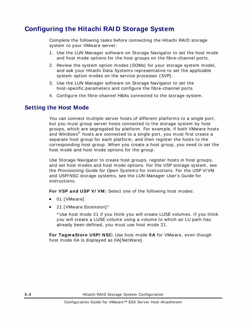
Configuring the Hitachi RAID Storage System
Complete the following tasks before connecting the Hitachi RAID storage system to your VMware server:
1. Use the LUN Manager software on Storage Navigator to set the host mode and host mode options for the host groups on the fibre-channel ports.
2. Review the system option modes (SOMs) for your storage system model, and ask your Hitachi Data Systems representative to set the applicable system option modes on the service processor (SVP).
3. Use the LUN Manager software on Storage Navigator to set the host-specific parameters and configure the fibre-channel ports.
4. Configure the fibre-channel HBAs connected to the storage system.
Setting the Host Mode
You can connect multiple server hosts of different platforms to a single port, but you must group server hosts connected to the storage system by host groups, which are segregated by platform. For example, if both VMware hosts and Windows® hosts are connected to a single port, you must first create a separate host group for each platform, and then register the hosts to the corresponding host group. When you create a host group, you need to set the host mode and host mode options for the group.
Use Storage Navigator to create host groups, register hosts in host groups, and set host modes and host mode options. For the VSP storage system, see the Provisioning Guide for Open Systems for instructions. For the USP V/VM and USP/NSC storage systems, see the LUN Manager User’s Guide for instructions.
For VSP and USP V/VM: Select one of the following host modes:
• 01 [VMware]
• 21 [VMware Extension]*
*Use host mode 21 if you think you will create LUSE volumes. If you think you will create a LUSE volume using a volume to which an LU path has already been defined, you must use host mode 21.
For TagmaStore USP/NSC: Use host mode 0A for VMware, even though host mode 0A is displayed as 0A[NetWare].

Setting the Host Mode Options
When you create a host group, you need to set the host mode and host mode options (HMOs) for the group. Table 3-1 lists the host mode options that apply to VMware host attachment.
Note: There may be additional host mode options that can be set for VMware operations. For a complete list of host mode options, see the Provisioning Guide for Open Systems for VSP, and see the LUN Manager User’s Guide for USP V/VM and USP/NSC.
Table 3-1 Host Mode Options for VMware Operations
Host Mode Option
Hitachi Storage System Model
Function Comments
13 VSP
USP V/VM
USP/NSC
This function provides SIM notification when the number of link failures detected between ports exceeds the threshold.
Optional
Configure this host mode option only when you are requested to do so.
16 USP/NSC only OPEN-V Geometry
When Host Mode Option 16 is ON or SOM 313 is ON, the same geometry shared by USP/NSC and 9900V can be responded to the host.
Power off the connected server when changing Host Mode Option 16 or SOM 313.
19 USP/NSC only Select this option when registering VMware server hosts in the host group.
This function reduces the processing time for the reserve command during I/O processing.
This function is enabled by default on the VSP and USP V/VM.
54 VSP
Select this option when using VAAI function.
70-01-6x-00/00 or later
Hitachi RAID Storage System Configuration 3-3
Configuration Guide for VMware™ ESX Server Host Attachment

3-4 Hitachi RAID Storage System Configuration
Configuration Guide for VMware™ ESX Server Host Attachment
Setting the System Option Modes
To provide greater flexibility and enable the Hitachi RAID storage system to be tailored to unique customer operating requirements, additional operational parameters called system option modes (SOMs) are available. At installation, the SOMs are set to their default values. The SOMs are set on the service processor (SVP) and can only be changed by the Hitachi Data Systems representative.
To ensure that the appropriate SOMs are set:
1. Review the SOMs for your storage system model. The SOMs are described in details in the User and Reference Guide for your storage system model:
– Hitachi VSP User and Reference Guide, MK-90RD7042
– Hitachi USP V/VM User and Reference Guide, MK-96RD635
– Hitachi USP/NSC User and Reference Guide, MK-94RD231
2. Discuss the SOMs with your Hitachi Data Systems representative, and ask the representative to set the SOMs that apply to your configuration and environment.

Configuring the Fibre-Channel Ports
The LUN Manager software on Storage Navigator is used to configure the FC ports. Table 3-2 explains the LUN Manager settings. Using LUN Manager, select the appropriate settings for each FC port based on the device to which the port is connected. Determine the topology parameters supported by the device and port type, and set your topology accordingly. For details and instructions, see the Provisioning Guide for Open Systems for VSP, and see the LUN Manager Users Guide for USP V/VM and USP/NSC.
Port address. In fabric environments, the port addresses are assigned automatically by fabric switch port number and are not controlled by the storage system port settings. If you plan to connect different types of servers to the storage system via the same fabric switch, use the zoning function of the fabric switch.
Topology. For information about port topology configurations supported by VMware versions and HBA/switch combinations, refer to the Hitachi Data Systems interoperability site: http://www.hds.com/products/interoperability.
Table 3-2 Fibre Parameter Settings
Hitachi RAID Storage System Configuration 3-5
Configuration Guide for VMware™ ESX Server Host Attachment
Fabric Connection Parameter Supported/Not Supported
Enable FC-AL Not supported
Enable Point-to-Point Supported
Disable FC-AL Supported
Disable Point-to-Point Not supported

3-6 Hitachi RAID Storage System Configuration
Configuration Guide for VMware™ ESX Server Host Attachment
Configuring the Fibre-Channel HBAs
Before connecting the Hitachi RAID storage system to the VMware system, configure the fibre-channel HBAs to be connected to the Hitachi RAID storage system. For information about supported HBAs, refer to the Hitachi Data Systems interoperability site: http://www.hds.com/products/interoperability
Check the manufacturer’s documentation for your fibre-channel HBAs for these options that are required to meet your operational requirements:
• Queue depth, BIOS, target reset, and FC topology parameters.
• Determine whether the BIOS must be disabled to prevent the system from booting from the Hitachi RAID storage system.
To prepare for connecting the Hitachi RAID storage system, configure the fibre-channel HBAs connected to the storage system. For information about configuring your HBAs, refer to these sources:
• Documentation that came with your HBA
• HBA vendor’s website
• Hitachi Data Systems interoperability site: http://www.hds.com/products/interoperability
• VMware Server Configuration Guide
The HBAs may require additional configuration. Refer to the user documentation for your HBA to ensure that all options required for your operational environment are set. After configuring the HBA, you may have to reset the VMware server to have the change take effect before restarting the VMware server.
Use the same settings and device parameters for all Hitachi RAID storage systems. Then, after configuring the HBAs, reset the VMware ESX Server to have the change take effect before booting to the VMware ESX Server.
The following subsections describe:
• Setting the queue depth parameter
• Configuring the BIOS of the HBAs for use with the Hitachi RAID storage system.

Hitachi RAID Storage System Configuration 3-7
Configuration Guide for VMware™ ESX Server Host Attachment
Setting the Queue Depth Parameter
You may need to change the queue depth value on the server. If the number is small, I/O performance can deteriorate and when this happens, the Hitachi RAID storage system reports a queue full status (because the queue depth exceeds an allowable limit). The system may not operate correctly when the queue is full and a large value is set. Set an appropriate number according to your configuration. If necessary, set a queue depth number for each server. Refer to the documentation for your HBA before setting a value.
Guidelines for settings:
• Queue depth: 32 commands per LU
• Commands per port:
– VSP: 2048
– USP V/VM: 2048
– TagmaStore USP/NSC: 1024
The following subsections provide sample procedures for setting queue depth on QLogic and Emulex HBAs. For information about other HBAs, refer to the documentation for your HBA or the HBA vendor’s website.
Setting the Queue Depth on QLogic HBAs
To set the queue depth parameter on QLogic HBAs:
1. Issue the following command to identify the HBA's driver name:
# vmkload_mode -l | grep qla
Sample output: qla2300_707_vmw
2. Issue the following command lines, with the following considerations:
Substitute the name output for <driver_name> parameter.
Substitute the queue depth value calculated for the "nn" parameter.
The last line reboots the server.
# esxcfg-module -s "ql2xmaxqdepth=nn" <driver_name>
# esxcfg-boot -b
# reboot

3-8 Hitachi RAID Storage System Configuration
Configuration Guide for VMware™ ESX Server Host Attachment
Setting the Queue Depth on Emulex HBAs
To set the queue depth parameter on Emulex HBAs:
1. Issue the following command to identify the driver name of each HBA: # vmkload_mode -l | grep lpfcdd
Sample output: lpfcdd_7xx
2. Issue one of the following command lines, with the following considerations:
Substitute the name output for <driver_name> parameter.
Substitute the queue depth value calculated for the "nn" parameter.
If your server has one Emulex HBA, issue the following command:
# esxcfg-module -s “lpfc0_lun_queue_depth=nn” <driver_name>
If your server has two Emulex HBAs, issue the following command:
# esxcfg-module -s "lpfc0_lun_queue_depth=nn lpfc1_lun_queue_depth=nn" <driver_name>
3. Issue the following command lines. The last line reboots the server.
# esxcfg-boot –b
# reboot

Configuring the HBA BIOS
This section provides sample instructions for configuring the BIOS on QLogic and Emulex HBAs. For information about other HBAs, refer to the documentation for your HBA or the HBA vendor’s website.
Configuring the QLogic HBA BIOS
The default VMware ESX Server driver is based on the QLogic-provided qla2x00 v6.07 driver. This driver has been tested with VMware ESX Server in various SAN fabric configurations. FC-AL configurations are currently not supported. The firmware for these devices is loaded by the driver. Point-to-point or direct connections are not supported unless otherwise noted.
Note: Normal traffic (I/O) may be suspended for up to 30 seconds before and after a firmware upgrade procedure is performed.
For information about supported HBAs for VMware ESX Server hosts, refer to the Hitachi Data Systems interoperability matrix: http://www.hds.com/products/interoperability
Use the following procedure to configure the QLogic HBA on the VMware ESX Server host for operation with the Hitachi RAID storage system. Other parameters may need to be configured depending on the environment.
1. Reboot the server.
2. During system startup, press CTL+Q to access the QLogic adapter settings menu.
3. Enter the QLogic HBA configuration utility during boot-up.
4. Access the Select Host Adapter page, select the HBA to be configured, and press Enter.
5. From the Configuration Settings, enter Restore Default Settings.
6. From the Host Adapter Settings, verify the following settings:
– BIOS Revision: 1.34 as the minimum level (check the VMware documentation for current QLogic firmware support).
– Host Adapter BIOS: Disabled
– Connection Options: 1 (Point-to-Point only) Default value is 2, press Enter and change the value to 1.
Hitachi RAID Storage System Configuration 3-9
Configuration Guide for VMware™ ESX Server Host Attachment

7. Return to the Configuration Settings, access the Advanced Adapter Settings window, and verify/set the number of LUNs per target (a number that adjusts to the number of LUNs of your configuration). Multiple LUN support is typically for RAID arrays that use LUNs to map drives. The default is 8. If you do not need multiple LUN support, set the number of LUNs to 0.
a. Enable LIP Reset: No
b. Enable LIP Full Login: Yes
c. Enable Target Reset: Yes
8. Save your changes, and repeat the configuration for the other HBAs.
Configuring the Emulex HBA BIOS
The VMware ESX Server drivers are based on the Emulex-provided lpfcdd-2xx 2.01g driver. This driver has been tested with VMware ESX Server in various fabric configurations. FC-AL configurations are not supported. Point-to-point and direct connections are not supported unless otherwise noted.
For information about supported HBAs for VMware ESX Server hosts, refer to the Hitachi Data Systems interoperability matrix: http://www.hds.com/products/interoperability
Note: Normal traffic (I/O) may be suspended for up to 30 seconds before and after a firmware upgrade procedure is performed.
For the latest information about supported Emulex HBA models, contact Hitachi Data Systems.
Use the following procedure to configure the Emulex HBA on the VMware ESX Server host for operation with the Hitachi RAID storage system. Other parameters may need to be configured depending on the environment.
1. Reboot the server.
2. During startup, press ALT+E to access the Emulex HBA settings menu.
3. Enter the Emulex HBA configuration utility during boot-up, and set these parameters:
– Enter a number to select the HBA to be configured, and press Enter.
– From the Adapter menu, enter 2 to configure the HBA’s parameters.
– HBA Firmware: at the minimum level (3.90a7 for LP9002, 1.00a4 LP9802DC).
– Host Adapter BIOS: Disabled (option 1)
– Topology Selection: Fabric Point-to-Point (option 4)
4. Repeat the configuration for the other HBAs.
5. Press X to exit, save your changes, and reboot the server.
3-10 Hitachi RAID Storage System Configuration
Configuration Guide for VMware™ ESX Server Host Attachment

Connecting the Storage System to the VMware Server
After you have prepared the Hitachi RAID storage system (host modes, host mode options, system option modes, fibre-channel ports) and configured the HBAs, the Hitachi RAID storage system can be connected to the VMware system. Some of these steps are performed by the Hitachi Data Systems representative, while other steps are performed by the user.
Note: The Hitachi Data Systems representative must use the Maintenance Manual during all installation activities. Follow all precautions and procedures in the Maintenance Manual, and always check all specifications to ensure proper installation and configuration.
To connect the Hitachi RAID storage system to the VMware Server host:
1. Verify the system installation. The Hitachi Data Systems representative verifies the configuration and operational status of the Hitachi RAID storage system fibre-channel ports, LDEVs, and paths.
2. Shut down and power off the VMware host. The user shuts down and powers off the VMware host. The power must be off when the FC cables are connected.
3. Connect the Hitachi RAID storage system to the VMware system. The Hitachi Data Systems representative connects the fibre-channel cables between the Hitachi RAID storage system and the VMware host or fabric switch. Verify the ready status of the storage system and peripherals.
4. Power on and boot the VMware system. The user powers on and boots the VMware system after the storage system has been connected:
a. Power on the VMware system display.
b. Power on all peripheral devices. The Hitachi RAID storage system must be on, and the fibre-channel ports must be configured. If the fibre-channel ports are configured after the VMware system is powered on, the system may need to be restarted to recognize the new devices.
c. Confirm the ready status of all peripheral devices, including the Hitachi RAID storage system.
d. Power on and boot the VMware system.
Hitachi RAID Storage System Configuration 3-11
Configuration Guide for VMware™ ESX Server Host Attachment

3-12 Hitachi RAID Storage System Configuration
Configuration Guide for VMware™ ESX Server Host Attachment
Storage Provisioning
The Hitachi LUN Manager software on Storage Navigator enables you to configure and manage host groups, ports, and LUN security. Host groups must be created to allow and control host access to LUNs. They are created per VMware cluster or per ESX host on the fibre channel ports on each storage cluster that the VMware cluster or the ESX hosts can access.
While host groups can be created with more than one WWN, it is recommended that you create one host group for each HBA and name the host group the same as the nickname for the HBA. Creating one host group per HBA provides flexibility and is the only supported configuration when booting hosts from a SAN.
If you are planning to use the the Hitachi Command Control Interface (CCI) software to perform operations on the storage system, you will use LUN Manager to set the command device for the Hitachi CCI software.
The LUN Expansion (LUSE) and Virtual LVI/LUN (VLL) software on Storage Navigator enable you to configure, reconfigure, and customize the logical devices on the Hitachi RAID storage system.
For information and instructions on these operations, see the applicable user documents for your storage system model (see Referenced Documents).

4
Creating a VMFS and Attaching Raw Devices 4-1
Configuration Guide for VMware™ ESX Server Host Attachment
Creating a VMFS and Attaching Raw Devices
This chapter provides instructions for creating a Virtual Machine File System (VMFS) and attaching raw devices:
Creating a Virtual Machine File System
Attaching a Raw Device
Creating a Virtual Machine File System
To create a VMFS:
1. Log on to your VMware ESX host or to your virtual center using VMware Infrastructure Client.
2. When the VMware Infrastructure page appears (see Figure 4-1), select a VMware host and click the Configuration tab in the VMware Infrastructure page.
Figure 4-1 Initial VMware Configuration Client Page
3. Under Hardware on the left side of the page, click Storage Adapters. A page similar to the one in Figure 4-2 appears. The storage adapters are named vmhba0, vmhba1. Each FC host port on the storage system becomes a SCSI target numbered in the order they have been discovered.
4-2 Creating a VMFS and Attaching Raw Devices
Configuration Guide for VMware™ ESX Server Host Attachment

4. Click Rescan in the top-right area above Storage Adapters (see Figure 4-2) to scan the fibre channel HBAs in your system for LUNs.
Figure 4-2 Storage Adapters Detail of Client Page
5. Select a fibre channel HBA under Storage Adapters. Then right-click a LUN in the lower part of the screen (under SCSI Target 0 in the figure above) and click Properties. A SAN_LUN Properties dialog box similar to the one in Figure 4-3 appears.
Figure 4-3 LUN Properties Dialog Box
Creating a VMFS and Attaching Raw Devices 4-3
Configuration Guide for VMware™ ESX Server Host Attachment

6. In the SAN_LUN_0 Properties dialog box, click Manage Paths. A Manage Paths dialog box similar to the one in Figure 4-4 appears. This dialog box shows the paths defined for the selected LUN. In the example, below, one path is active while the other path is on.
Figure 4-4 Manage Paths Dialog Box
7. In the Policy area, click the Change button. The Manage Paths - Selection Policy dialog box appears. The default policy is Fixed. The recommended path policy is Fixed as shown in Figure 4-5.
Figure 4-5 Manage Paths Selection Policy Dialog Box
4-4 Creating a VMFS and Attaching Raw Devices
Configuration Guide for VMware™ ESX Server Host Attachment
8. Click OK to exit the Manage Paths - Selection Policy dialog box.
9. When the Change Path State dialog box appears, click the Change button in the lower right side of the dialog box. The Change Path State dialog box appears (see Figure 4-6).
Figure 4-6 Change Path State Dialog Box
10. Confirm that Preferred is checked and that under State Enabled is selected.
11. Click OK to exit the Change Path State dialog box.
12. Click OK to exit the Managed Paths dialog box.
13. Click Close to exit the LUN Properties dialog box.
14. From the VMware Infrastructure page, select a VMware host in the left pane and click Storage under Hardware.
15. Click Add Storage in the top right the top-right area above Storage. When the Add Storage Wizard starts the Select Storage Type screen displays (see Figure 4-7).
Creating a VMFS and Attaching Raw Devices 4-5
Configuration Guide for VMware™ ESX Server Host Attachment

Figure 4-7 Add Storage Wizard Screen
16. Under Storage Type, select Disk/LUN (if it is not already selected), then click Next. The Select Disk /LUN screen appears (see Figure 4-8 ).
Figure 4-8 Select Disk/LUN Screen
4-6 Creating a VMFS and Attaching Raw Devices
Configuration Guide for VMware™ ESX Server Host Attachment

17. Select the LUN on which you want to create the VMFS and click Next. The Current Disk Layout screen appears (see Figure 4-9).
Figure 4-9 Current Disk Layout Screen
18. Click Next. The Disk/LUN Properties screen appears (see Figure 4-10).
Figure 4-10 Disk/LUN Properties Screen
Creating a VMFS and Attaching Raw Devices 4-7
Configuration Guide for VMware™ ESX Server Host Attachment

19. Under Datastore Name, enter a name for the VMFS volume and click Next. The Disk/LUN Formatting screen in Figure 4-11 appears.
Figure 4-11 Add Storage Wizard Disk Formatting Screen
20. Accept the default selection in the Disk LUN Formatting screen and confirm that Maximize capacity under Capacity is checked and click Next. The Ready to Complete screen appears (see Figure 4-12).
4-8 Creating a VMFS and Attaching Raw Devices
Configuration Guide for VMware™ ESX Server Host Attachment
Figure 4-12 Ready to Complete Screen
21. Review the summary information displayed. If you need to change a setting, click Back to return to the appropriate screen, change the setting, and click Next until you return to the Ready to Complete screen.
22. When you are satisfied that the settings are correct, click Finish.
23. If needed, repeat steps 15 through 22 to create additional VMFSes.
TIP: On any additional hosts that will need access to the LUN you just created, you do not have to create the VMFSes again. Instead, on the other host, click Refresh above Storage on the VMware Infrastructure page.
This completes the procedure for creating a VMFS. Proceed to the section below for instructions on attaching a raw device.
Creating a VMFS and Attaching Raw Devices 4-9
Configuration Guide for VMware™ ESX Server Host Attachment
Attaching a Raw Device
The following procedure describes how to attach a raw device, such as a command device, to a virtual machine.
1. From the VirtualCenter client, right-click a virtual machine and select Edit Settings. The Virtual Machine Properties dialog box appears (see Figure 4-13).
Figure 4-13 Virtual Machine Properties Dialog Box
2. Select Add. The Add Hardware Device wizard starts, with the Select Device Type screen displayed (see Figure 4-14).
4-10 Creating a VMFS and Attaching Raw Devices
Configuration Guide for VMware™ ESX Server Host Attachment

Figure 4-14 Select Device Type Screen
3. Select Hard Disk and click Next. The Select a Disk Screen appears.
4. Select Raw Device Mappings, as shown in Figure 4-15.
Figure 4-15 Select a Disk Screen
Creating a VMFS and Attaching Raw Devices 4-11
Configuration Guide for VMware™ ESX Server Host Attachment

5. Click Next. The Select and Configure a Raw LUN screen appears (see Figure 4-16).
Figure 4-16 Select and Configure a Raw LUN Screen
6. Select the LUN you want to use for the raw device (Command Device) and click Next. The Select a Datastore screen appears (see Figure 4-17).
Figure 4-17 Select a Datastore Screen
4-12 Creating a VMFS and Attaching Raw Devices
Configuration Guide for VMware™ ESX Server Host Attachment

7. Confirm that Store with Virtual Machine is selected. If it is not, select it and click Next. The Select Compatibility Mode screen appears (see Figure 4-18).
Figure 4-18 Select a Datastore ScreenSelect Compatibility Mode
8. Under Compatibility, confirm that Physical is selected. If it is not selected, select it. Click Next. The Specify Advanced Options screen appears (see Figure 4-19).
Figure 4-19 Specify Advanced Options Screen
Creating a VMFS and Attaching Raw Devices 4-13
Configuration Guide for VMware™ ESX Server Host Attachment

9. Under Virtual Device Node, select a virtual device node local to the Virtual Machine and click Next. The Ready to Complete Screen appears (see Figure 4-20).
Figure 4-20 Ready to Complete Screen
10. Review the summary information displayed. To change a setting, click the Back button to return to the appropriate screen, change the setting, and click Next until you return to the Ready to Complete screen.
11. After confirming that the settings are correct, click Finish. The Virtual Machine Properties dialog box appears (see Figure 4-21).
4-14 Creating a VMFS and Attaching Raw Devices
Configuration Guide for VMware™ ESX Server Host Attachment

Figure 4-21 Virtual Machine Properties Dialog Box
12. Click OK to exit the Virtual Machine Properties dialog box.
13. Right-click the same virtual machine and select Edit Settings. The Virtual Machine Properties dialog box appears, with the new SCSI controller and hard disk you added (see Figure 4-22).
Figure 4-22 Virtual Properties Dialog Box with New SCSI Controller and Hard Disk Added
14. Click Cancel to exit the Virtual Properties dialog box.
Creating a VMFS and Attaching Raw Devices 4-15
Configuration Guide for VMware™ ESX Server Host Attachment

4-16 Creating a VMFS and Attaching Raw Devices
Configuration Guide for VMware™ ESX Server Host Attachment

5
Troubleshooting 5-1
Configuration Guide for VMware™ ESX Server Host Attachment
Troubleshooting
This chapter provides troubleshooting information for VMware host attachment and includes instructions for calling technical support.
General Troubleshooting
Calling the Hitachi Data Systems Support Center

5-2 Troubleshooting
Configuration Guide for VMware™ ESX Server Host Attachment
General Troubleshooting
Table 5-1 lists potential error conditions during device configuration and provides instructions for resolving each condition. If you cannot resolve an error condition, contact your Hitachi Data Systems representative, or call the Hitachi Data Systems Support Center for assistance (see Calling the Hitachi Data Systems Support Center for instructions).
For troubleshooting information for the Hitachi RAID storage system, see the User and Reference Guide for the storage system (e.g., Hitachi Virtual Storage Platform User and Reference Guide).
For troubleshooting information for Hitachi Storage Navigator, see the Storage Navigator User’s Guide for the storage system (e.g., Hitachi Virtual Storage Platform Storage Navigator User’s Guide).
For information about error messages displayed by Storage Navigator, see the Storage Navigator Messages document for the storage system (e.g., Hitachi Virtual Storage Platform Storage Navigator Messages).

Troubleshooting 5-3
Configuration Guide for VMware™ ESX Server Host Attachment
Table 5-1 General Troubleshooting
Error Condition Recommended Action
Virtual Machine HBA does not see Lun8 and greater.
Verify cabling, storage LUN, switch and storage security and LUN masking. Verify that the Disk.MaxLUN parameter in the Advance Settings (VMware Management Interface) is set to more than 7.
Guest OS virtual machine booting up but not installing the OS.
It is possible that there is an existing corrupted vmdk file (due to an incomplete installation). Delete the vmdk file from the File Manager and remove it from the Guest OS. Add a new device for the Guest OS and recreate a new vmdk image file.
Cannot add Meta Data File for raw device.
The Meta Data File for the raw device may have existed. Selected the existing Meta Data File or delete the old Meta Data File and create a new one.
Guest OS virtual machine boots up, but does not install the operating system.
There may be a corrupt vmdk file (usually because of previous incomplete installation). Delete the vmdk file from the File Manager and remove it from the Guest OS. Add a new device for the Guest OS and recreate a new vmdk image file.
Cannot add Meta Data File for raw device.
The Meta Data File for the raw device may have existed. Selected the existing Meta Data File or delete the old Meta Data File and create a new one.
Volume label is not successful. Limit the number of characters to 30.
Cannot delete a VMFS file. It is possible that there is an active swap file on the same extended partition. Manually turn off the swap device (using vmkfstools command) from the service console and try again. Relocate the swap file to another disk.
Guest OS cannot communicate with the server or outside network.
Make sure a virtual switch is created and bound to a connected network adapter.
Vmkfstools –s does not add LUN online.
Delete the LUN. Select and add another LUN and retry the process again. Repeat the command or perform the Rescan SAN function in the Storage Management of the VMware Management Interface and display again.
Service console discovers online LUN addition but the Disks and LUNs does not.
Rescan SAN and refresh.
VMware ESX Server crashes while booting up.
Check for the error message on the screen. It could be because of mixing different types of HBA in the server.
5-4 Troubleshooting
Configuration Guide for VMware™ ESX Server Host Attachment
Calling the Hitachi Data Systems Support Center
If you need to call the Hitachi Data Systems Support Center, make sure to provide as much information about the problem as possible, including:
• The circumstances surrounding the error or failure.
• The content of any error messages displayed on the host systems.
• The content of any error messages displayed on Storage Navigator.
• The Storage Navigator configuration information (use the FD Dump Tool).
• The service information messages (SIMs), including reference codes and severity levels, displayed by Storage Navigator.
The Hitachi Data Systems customer support staff is available 24 hours a day, seven days a week. If you need technical support, log on to the Hitachi Data Systems Portal for contact information: https://hdssupport.hds.com

A
Specifications for Device Types A-1
Configuration Guide for VMware™ ESX Server Host Attachment
Specifications for Device Types
Table A-1 provides the specifications for the device emulation types that can be configured on the Hitachi RAID storage systems. Some device types and parameters may not be relevant to your storage system model.
For more information about device emulation types and configuring devices other than OPEN-V on your storage system, please contact your Hitachi Data Systems account team.
Please note the following:
• The logical devices on the Hitachi RAID storage systems are defined to the host as SCSI disk devices, even though the interface is fibre channel.
• The sector size for the device types is 512 bytes.
Table A-1 Device Specifications
Device Type (Note 1)
Product Name(Note 2)
No. of Blocks (512 B/blk)
Number of Cylinders
No. of Heads
# of Sectors per Track
Capacity (MB)
(Note 3)
OPEN-3 OPEN-3 4806720 3338 15 96 2347
OPEN-8 OPEN-8 14351040 9966 15 96 7007
OPEN-9 OPEN-9 14423040 10016 15 96 7042
OPEN-E OPEN-E 28452960 19759 15 96 13893
OPEN-L OPEN-L 71192160 49439 15 96 34761
OPEN-V OPEN-V 125827200 max Note 4
Note 5 15 128 Note 6
OPEN-3*n OPEN-3*n 4806720*n 3338*n 15 96 2347*n
OPEN-8*n OPEN-8*n 14351040*n 9966*n 15 96 7007*n
OPEN-9*n OPEN-9*n 14423040*n 10016*n 15 96 7042*n
OPEN-E*n OPEN-E*n 28452960*n 19759*n 15 96 13893*n
OPEN-L*n OPEN-L*n 71192160*n 49439*n 15 96 34761*n
OPEN-3 VLL OPEN-3-CVS Note 4 Note 5 15 96 Note 6
OPEN-8 VLL OPEN-8-CVS Note 4 Note 5 15 96 Note 6

A-2 Specifications for Device Types
Configuration Guide for VMware™ ESX Server Host Attachment
Device Type (Note 1)
Product Name(Note 2)
No. of Blocks (512 B/blk)
Number of Cylinders
No. of Heads
# of Sectors per Track
Capacity (MB)
(Note 3)
OPEN-9 VLL OPEN-9-CVS Note 4 Note 5 15 96 Note 6
OPEN-E VLL OPEN-E-CVS Note 4 Note 5 15 96 Note 6
OPEN-V VLL OPEN-V Note 4 Note 5 15 128 Note 6
OPEN-3*n VLL OPEN-3*n-CVS Note 4 Note 5 15 96 Note 6
OPEN-8*n VLL OPEN-8*n-CVS Note 4 Note 5 15 96 Note 6
OPEN-9*n VLL OPEN-9*n-CVS Note 4 Note 5 15 96 Note 6
OPEN-E*n VLL OPEN-E*n-CVS Note 4 Note 5 15 96 Note 6
OPEN-V*n VLL OPEN-V*n Note 4 Note 5 15 128 Note 6
Note 1: The availability of specific device types depends on the storage system model and the level of microcode installed on the storage system.
Note 2: The command device (used for Command Control Interface operations) is distinguished by -CM on the product name (e.g., OPEN-3-CM, OPEN-3-CVS-CM). The product name for VLL devices is OPEN-x-CVS, where CVS stands for custom volume size.
Note 3: This capacity is the maximum size that can be configured on the host. The device capacity can sometimes be changed by the BIOS or host bus adapter. Also, different capacities may be due to variations such as 1 MB = 10002 or 10242 bytes.
Note 4: The number of blocks for a VLL volume is calculated as follows:
# of blocks = (# of data cylinders) × (# of heads) × (# of sectors per track)
The number of sectors per track is 128 for OPEN-V and 96 for the other emulation types.
Example: For an OPEN-3 VLL volume with capacity = 37 MB:
# of blocks = (53 cylinders – see Note 2) × (15 heads) × (96 sectors per track) = 76320
Note 5: The number of data cylinders for a VLL volume is calculated as follows (↑…↑ means that the value should be rounded up to the next integer):
• Number of data cylinders for OPEN-x VLL volume (except for OPEN-V) = # of cylinders = ↑ (capacity (MB) × 1024/720 ↑
Example: For OPEN-3 VLL volume with capacity = 37 MB:
# of cylinders = ↑37 × 1024/720↑ = ↑52.62↑ = 53 cylinders

Specifications for Device Types A-3
Configuration Guide for VMware™ ESX Server Host Attachment
• Number of data cylinders for an OPEN-V VLL volume = # of cylinders = ↑ (capacity (MB) specified by user) × 16/15 ↑
Example: For OPEN-V VLL volume with capacity = 50 MB:
# of cylinders = ↑50 × 16/15↑ = ↑53.33↑ = 54 cylinders
• Number of data cylinders for a VLL LUSE volume (except for OPEN-V) = # of cylinders = ↑ (capacity (MB) × 1024/720 ↑ × n
Example: For OPEN-3 VLL LUSE volume with capacity = 37 MB and n = 4:
# of cylinders = ↑37 × 1024/720↑ × 4 = ↑52.62↑ × 4 = 53 × 4 = 212
• Number of data cylinders for an OPEN-V VLL LUSE volume = # of cylinders = ↑ (capacity (MB) specified by user) × 16/15 ↑ × n
Example: For OPEN-V VLL LUSE volume with capacity = 50 MB and n = 4:
# of cylinders = ↑50 × 16/15↑ × 4 = ↑53.33↑× 4 = 54 × 4 = 216
Note 6: The size of an OPEN-x VLL volume is specified by capacity in MB, not number of cylinders. The size of an OPEN-V VLL volume can be specified by capacity in MB or number of cylinders. The user specifies the volume size using the Virtual LVI/LUN software.

A-4 Specifications for Device Types
Configuration Guide for VMware™ ESX Server Host Attachment

B
Using VMware with Hitachi RAID Storage Systems B-1
Configuration Guide for VMware™ ESX Server Host Attachment
Using VMware with Hitachi RAID Storage Systems
This appendix provides reference information to help you implement VMware software with the Hitachi RAID storage systems:
VMware ESX Server and VirtualCenter Compatibility
Installing and Configuring VMware
Creating and Managing VMware Infrastructure Components

B-2 Using VMware with Hitachi RAID Storage Systems
Configuration Guide for VMware™ ESX Server Host Attachment
VMware ESX Server and VirtualCenter Compatibility
VMware recommends that you install VirtualCenter with the ESX Server software. VirtualCenter lets you provision virtual machines and monitor performance of physical servers and virtual machines, monitor performance and utilization of physical servers and the virtual machines they are running, and export VirtualCenter data to HTML and Excel formats for integration with other reporting tools.
It is vital that you make sure that your ESX server and VirtualCenter versions are compatible. For information about the VirtualCenter versions compatible with the VMware ESX server versions, please refer to your VMware Release Notes and the VMware website at www.vmware.com.

Using VMware with Hitachi RAID Storage Systems B-3
Configuration Guide for VMware™ ESX Server Host Attachment
Installing and Configuring VMware
For your VMware installation to succeed, it is important to verify that your server, I/O, storage, guest operating system, management agent, and backup software are all compatible before you install and configure VMware.
The following sections identify the VMware documentation to consult for information about installing and configuring VMware ESX Server. These documents also contain compatibility information.
Installing and Configuring VMware ESX Server
Refer to the VMware documentation when installing and configuring VMware ESX Server. Be sure to follow the configuration steps for licensing, networking, and security.
Upgrading an ESX Server and VirtualCenter Environment
Refer to the VMware documentation when upgrading an ESX Server and VirtualCenter environment.

B-4 Using VMware with Hitachi RAID Storage Systems
Configuration Guide for VMware™ ESX Server Host Attachment
Creating and Managing VMware Infrastructure Components
After you install VMware ESX Server on a host, you have completed the installation of all the major components of the VMware Infrastructure. You can then perform the following steps to manage your VMware infrastructure components.
• Use the VI client to manage your ESX Server hosts either as a group through VirtualCenter or individually by connecting directly to the host.
• Set up a datacenter to bring one or more ESX Server hosts under VirtualCenter management, create virtual machines, and determine how you want to organize virtual machines and manage resources.
• Create a Virtual Machine manually, from templates, or by cloning existing virtual machines.
• Configure permissions and roles for users to allocate access to VirtualCenter, its administrative functions, and its resources.
• Use resource pools to partition available CPU and memory resources hierarchically.
• Configure network connections to ensure that virtual machine traffic does not share a network adapter with the service console for security purposes.
• Install a guest operating system in a virtual machine.
• Manage virtual machines to learn how to power them on and off.
• Monitor the status of your virtual infrastructure using tasks and events.
• Schedule automated tasks to perform actions at designated times.
• Configure alarm notification messages to be sent when selected events occur to or on hosts or virtual machines.

Acronyms and Abbreviations Acronyms-1
Configuration Guide for VMware™ ESX Server Host Attachment
Acronyms and Abbreviations
AL arbitrated loop AL-PA arbitrated loop physical address
blk block
CU control unit CVS custom volume size
FC fibre-channel FC-AL Fibre-channel arbitrated loop FCP fibre-channel protocol
GB gigabyte
HBA host bus adapter HMO host mode option
I/O input/output
LDEV logical device LU logical unit LUN logical unit, logical unit number LUSE LU Size Expansion
MB megabyte
NSC Hitachi TagmaStore Network Storage Controller
OFC open fibre control
PA physical address PB petabyte PC personal computer system
RAID redundant array of independent disks
SCSI small computer system interface SIM service information message SOM system option mode
TB terabyte

Acronyms-2 Acronyms and Abbreviations
Configuration Guide for VMware™ ESX Server Host Attachment
USP Hitachi TagmaStore Universal Storage Platform USP V Hitachi Universal Storage Platform V USP VM Hitachi Universal Storage Platform VM
VLL Hitachi Virtual LVI/LUN VSP Hitachi Virtual Storage Platform

Configuration Guide for VMware™ ESX Server Host Attachment
Hitachi Data Systems
Corporate Headquarters 750 Central Expressway Santa Clara, California 95050-2627 U.S.A. Phone: 1 408 970 1000 www.hds.com [email protected]
Asia Pacific and Americas 750 Central Expressway Santa Clara, California 95050-2627 U.S.A. Phone: 1 408 970 1000 [email protected]
Europe Headquarters Sefton Park Stoke Poges Buckinghamshire SL2 4HD United Kingdom Phone: + 44 (0)1753 618000 [email protected]
MK-98RD6716-03