cnc 2 axis control system - dc services. services 2 axis controller page 4 of 19 1. overview the...
TRANSCRIPT

CNC
2 Axis
Control System
Revision 1.01
Vision
Thursday, 16 August 2007

D.C. Services 2 Axis Controller Page 2 of 19
D.C. Services 2 Axis Controller Page 3 of 19
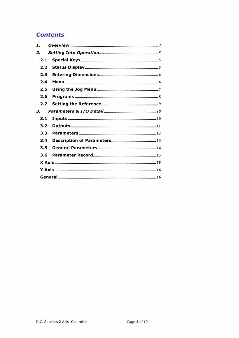
Contents
1. Overview ....................................................................................... 4
2. Setting Into Operation.......................................................... 5
2.1 Special Keys ............................................................................ 5
2.2 Status Display ........................................................................ 5
2.3 Entering Dimensions .......................................................... 6
2.4 Menu ............................................................................................ 6
2.5 Using the Jog Menu ............................................................ 7
2.6 Programs .................................................................................. 8
2.7 Setting the Reference........................................................ 9
3. Parameters & I/O Detail ................................................... 10
3.1 Inputs ....................................................................................... 10
3.2 Outputs .................................................................................... 11
3.3 Parameters ............................................................................ 12
3.4 Description of Parameters............................................ 13
3.5 General Parameters.......................................................... 14
3.6 Parameter Record.............................................................. 15
X Axis .................................................................................................... 15
Y Axis .................................................................................................... 16
General................................................................................................. 16

D.C. Services 2 Axis Controller Page 4 of 19
1. Overview
The control system is a CNC Controller for providing 2 axis control for two speed motors.
The controllers actual position is constantly monitored against the software limits. The
system cannot be driven past these limits in either manual jog mode or normal running mode.
This software monitoring also slows the motor down as the limits are approached.
There are 200 programs arranged as program numbers 1 – 200. each program can consist of
a maximum of 20 lines of both X and Y positions.

D.C. Services 2 Axis Controller Page 5 of 19
2. Setting Into Operation
When the machine is switched on and the initialisation process completed the controller will
be in the program/run screen.
No axis movement can take place until the system status reads “OK” i.e. the “STOP” input
must not be activated.
2.1 Special Keys
Enter Key - Used to accept the data entry
ESC - Reset the system to data entry mode. Any partially completed input will
be ignored. If held down for 1 second will revert the program to line
number 1.
F3 - Moves the program to the previous line
F6 - Moves the program to the next line
2.2 Status Display
System Status displays the following Messages
OK - The Stop input is in active, which usually indicates that the safety circuit is
on.
STOP! - The stop input has been activated
MOVING - An axis is currently moving
S.LIMIT - Software Limit has been activated whilst trying to move
X – H.LIMIT - The X axis “Hard limit” has been activated
Y – H.LIMIT - The Y axis “Hard limit” has been activated
ENTRY ERROR - The data entered is beyond the programmed software limits

D.C. Services 2 Axis Controller Page 6 of 19
2.3 Entering Dimensions
1. Press the ESC key 2. The cursor in front of the demand X value will flash 3. Type in the required dimension and press ENTER 4. The cursor moves to the Y demand 5. Enter the required demand and press ENTER 6. The cursor will be switched off indicating that data entry is complete
F2 can be used to toggle the program end.
At any point data entry can be abandoned by pressing the ESC key.
The system will check the dimensions against software limits and should a value be entered
that is erroneous a message will be displayed.
Whilst any of the axes are moving the Machine Blocked Output is de-energises. This can be
used to prevented unwanted machine operation
2.4 Menu
There is a System Menu which allows the user access to further operations of the system
From the Operating Screen press the F1 key
The System Menu will be displayed
F1 - Back to the Program/Run Screen
F2. - Recalibrate the actual positions
F3 - Access the configuration parameters
F4 - Jog the axis using keyboard buttons
F5 - Select and manage programs
F6 - Return to Run/Prog screen
ESC - Return to the Operating Screen

D.C. Services 2 Axis Controller Page 7 of 19
2.5 Using the Jog Menu
In some instances it may be necessary to jog either the X or Y axis. This can be done by
selecting Manual Option from the System Menu
The X axis can be jogged using the following buttons
1 - Slow Forward
2 - Fast Forward
+/- - Slow Reverse
3 - Fast Reverse
The Y axis can be jogged using the following buttons
7 - Slow Forward
8 - Fast Forward
0 - Slow Reverse
9 - Fast Reverse
To return to the Operating Screen press F6

D.C. Services 2 Axis Controller Page 8 of 19
2.6 Programs
There are 200 programs available fro the user. These are numbed 1 – 200. From the System
Menu using F5
The menu allows the user to
1. Select the program number to use. Select F5 . Enter the program number to use
then press enter.
2. Erase the data in the currently selected program. Press F3. The user will be
asked to confirm this by pressing F3
3. Erase all the data in the controller memory. Press F3. The user will be asked to
confirm this.
When options 2 and 3 are complete the user is automatically returned to the program menu.,

D.C. Services 2 Axis Controller Page 9 of 19
2.7 Setting the Reference
Should the actual position no longer represent the real positions of the axes it will be
necessary to recalibrate the controller. This situation can arise if any of the axes are moved
with the power to the controller switched off, for example during maintenance.
Resetting the reference is achieved as follows
1. Jog the X to an accurately measured position. 2. From the System Menu select “SET REF” 3. press F1 or F2 to select the axis to reference 4. Enter the measured value 5. Select F3to reference X axis 6. Select F6 to return

D.C. Services 2 Axis Controller Page 10 of 19
3. Parameters & I/O Detail
3.1 Inputs
Input No Designation Description
I0.0 Encoder X A Channel
I0.1 Encoder X B Channel
I0.2 Encoder Y A Channel
I0.3 Encoder Y B Channel
I0.4 Stop Cancels all moves
I0.5 Start X Start X axis. If Start X & Y is set
then this input will start both axis
simultaneously
I0.6 Increment Program Increment the program to the next
line
I0.7 Start X Start Y
I0.8
Limit X Positive Hard Limits
I0.9 Limit X Negative
I1.0 Limit Y Positive
I1.1 Limit Y Negative
I1.2 Unused
I1.3 Unused
I1.4 Unused
I1.5 Simulation Mode Simulates movement of the axis.

D.C. Services 2 Axis Controller Page 11 of 19
3.2 Outputs
Output No Designation Description
Q0.0 Machine Blocked A move is in operation
Q0.1 Forward Output On when driving to a lower position than the
demand,
Q0.2 Reverse Output On when driving to a higher position than the
demand
Q0.3 Fast Energised when
(Demand – Actual Position) >Slow
Q0.4
Q0.5 Forward Output On when driving to a higher position than the
demand
Q0.6 Reverse Output On when driving to a higher position than the
demand
Q0.7 Fast Energised when
(Demand – Actual Position) >Slow
Q0.8
Q0.9 Program End The program is complete

D.C. Services 2 Axis Controller Page 12 of 19
3.3 Parameters
The parameters define how the control system should operate and should only be changed by
trained personnel or under the supervision of one. To prevent accidental overwriting of the
data the parameter screen is passcode protected.
Select "PARAMS" from the System Menu and operator is prompted for access code.
The access code is 6809
The parameter screen will now be displayed. There are three screens which can be accessed
by pressing the left or right arrow keys. If a mistake is made the ESC key will abandon all
data entry.
F6 will return the user to the Operation Screen.
D.C. Services 2 Axis Controller Page 13 of 19
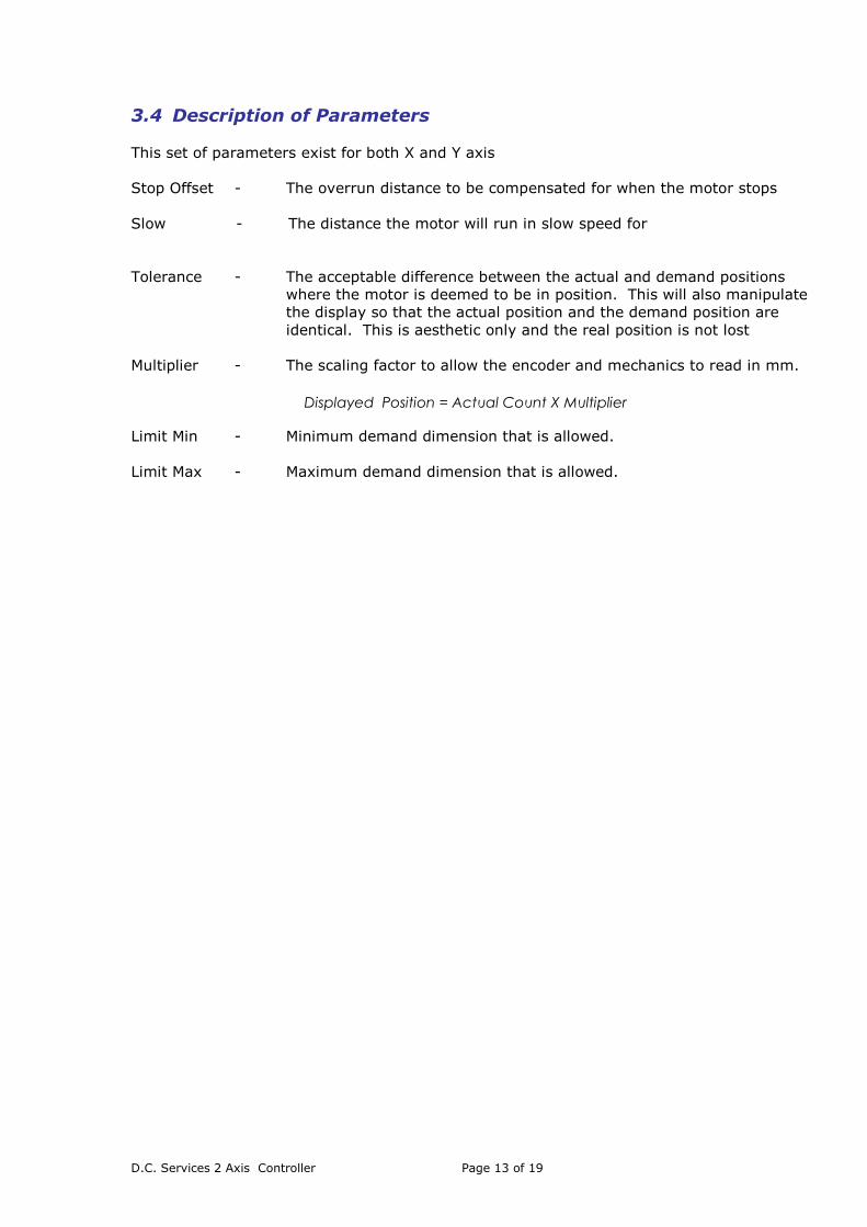
3.4 Description of Parameters
This set of parameters exist for both X and Y axis
Stop Offset - The overrun distance to be compensated for when the motor stops
Slow - The distance the motor will run in slow speed for
Tolerance - The acceptable difference between the actual and demand positions
where the motor is deemed to be in position. This will also manipulate
the display so that the actual position and the demand position are
identical. This is aesthetic only and the real position is not lost
Multiplier - The scaling factor to allow the encoder and mechanics to read in mm.
Limit Min - Minimum demand dimension that is allowed.
Limit Max - Maximum demand dimension that is allowed.
Displayed Position = Actual Count X Multiplier
D.C. Services 2 Axis Controller Page 14 of 19
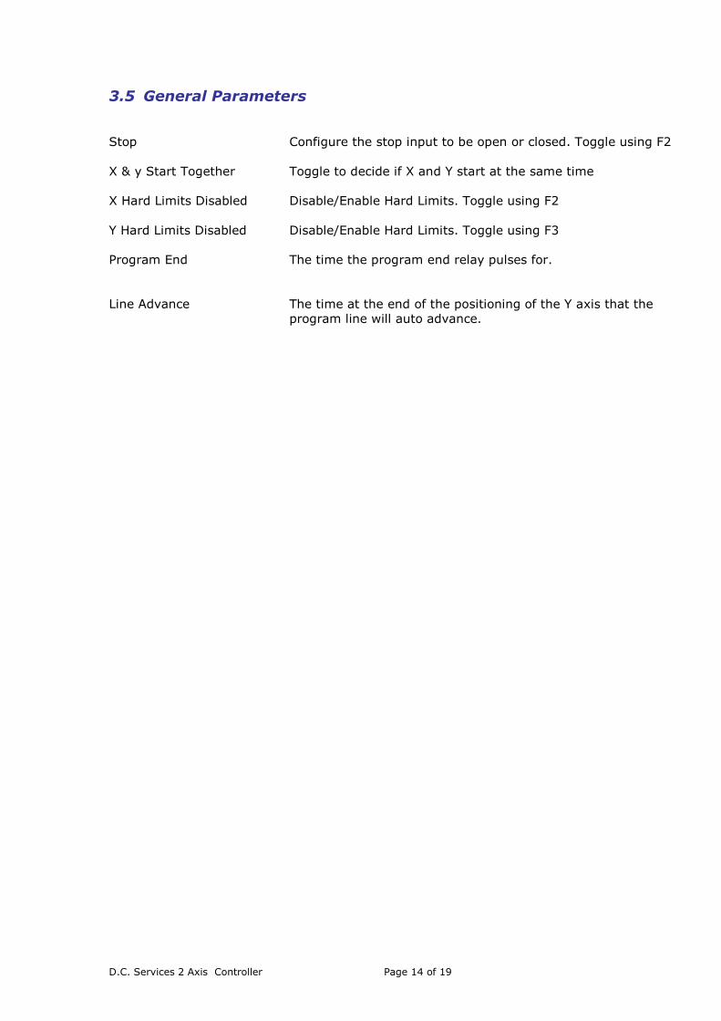
3.5 General Parameters
Stop Configure the stop input to be open or closed. Toggle using F2
X & y Start Together Toggle to decide if X and Y start at the same time
X Hard Limits Disabled Disable/Enable Hard Limits. Toggle using F2
Y Hard Limits Disabled Disable/Enable Hard Limits. Toggle using F3
Program End The time the program end relay pulses for.
Line Advance The time at the end of the positioning of the Y axis that the
program line will auto advance.

D.C. Services 2 Axis Controller Page 15 of 19
3.6 Parameter Record
Once the system has been commissioned we advise that all parameter settings are noted so
that in the event of a failure data can easily be re-entered.
X Axis
Parameter Value
Stop offset
Creep
Slow
Tolerance
Backlash
Multiplier
Limit Min
Limit Max

D.C. Services 2 Axis Controller Page 16 of 19
Y Axis
Parameter Value
Stop offset
Creep
Slow
Tolerance
Backlash
Multiplier
Limit Min
Limit Max
General
Parameter Value
Stop Active
X & Y Start Together
X Hard Limits Disabled
Y Hard Limits Disabled

D.C. Services 2 Axis Controller Page 17 of 19
Notes

D.C. Services 2 Axis Controller Page 18 of 19

D.C. Services 2 Axis Controller Page 19 of 19
Copyright D.C. Services 2007 all rights reserved.
This manual is copyright of D.C. Services and all rights are reserved. This document may not,
in whole or in part, be copied or reproduced in any form whatsoever without the prior written
consent of D.C. Services.
D.C. Services makes no representations or warranties with respect to the contents hereof and
specifically disclaims any implied warranties of fitness for any particular purpose. The
information in this document is subject to change without notice. D.C. Services assumes no
responsibility for any errors that may appear in this document.