chapter 2 diode applications - educypediaeducypedia.karadimov.info/library/ch_2_pdf.pdfchapter 2...
TRANSCRIPT

Chapter 2Diode Applications
� In general, approximate model of diode is used in applications because of non-ideal real life conditions (tolerance, temperature effect, etc) never allow an ideal case to be applied
Load Line Analysis
� The load of a circuit determines the point or the region of operation of a diode (or device)
� The method: A line is drawn on the characteristic of the device
� The intersection point gives the point of operation


Load Line Analysis
� In the above figure, E has to be in the forward bias direction and > VT of the diode, in order for the current to flow. Using KVL:
� -E + VD + VR = 0� E = VD + VR = VD + IDR� Notice: Variables VD , ID are
same in the above equation� For VD=0: ID = E/R� For ID=0: E = VD + IDR

Load Line Analysis
� The intersection point is called Q point
� Same solution can be found by using nonlinear diode equation
� We can avoid heavy math using load line analysis.
� Exp from notes 1� Exp from notes 2� Exp from notes 3

Example 1
� For below figure, determine VDQ, IDQ and VR

Solution
� Refer to notes for the solution

Example 2
� Repeat the previous example using approximate model of the Si diode
� Solution: Refer to notes and see the next figure

Solution to Example 2.

Example 3
� Repeat the same example using ideal model of the diode
� Solution: Refer to notes and see next figure

Solution to example 3 using ideal model

Diode Approximations
� As an engineer, we will generally use approximate models to avoid extensive mathematical calculations
� This is achieved by using approximate model of a device whenever it is possible
� Approximate model of diodes are given in Table 2.1
� Also see Figure 2.11

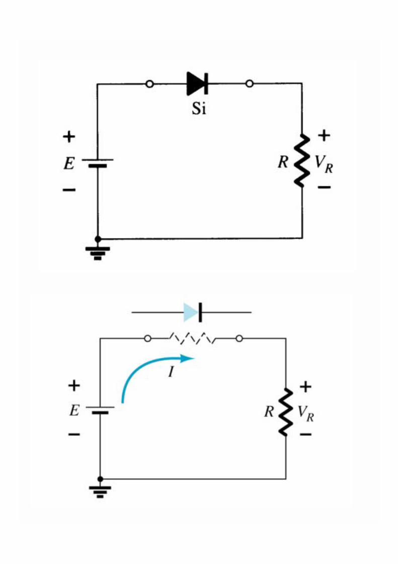
Series Diode Config. with DC Inputs
� When connected to voltage sources in series, the diode is on if the applied voltage is in the direction of forward-bias and it is greater than the VT of the diode
� When a diode is on, we can use the approximate model for the on state
� See next two figures

Using equivalent model of the diode in the forward-bias region
Series Diode Config. with DC Inputs
� Here, VD = VT, VR = E - VT
� ID = IR = VR / R� When the diode is in the off
state, the model for the off state is used
� See two figures� Here, VD = E, VR = 0, ID = 0� Keep in mind that KVL has to
be satisfied under all conditions� Exp from notes 1,2,3,4,5


Example 4
� For the figure below, determine VD, ID, and VR
� Refer to notes for the solution

� For the figure below, determine VD, ID, and VR
� Refer to notes for the solution
Example 5

� Determine VD2 , ID and V0 for the figure below
� Refer notes for the solution
Example 6

� Determine I1 , V1 , V2 and V0 for the figure below
� Refer to notes for the solution
Example 7

Parallel Diode Configurations
� Determine I1 , VD1 , VD2 and V0 for the paralel doide circuit in below figure
� Refer to notes for the solution

Determining unknown quantities

Example 9
� Determine the current I for the circuit below
� Refer to notes for the solution
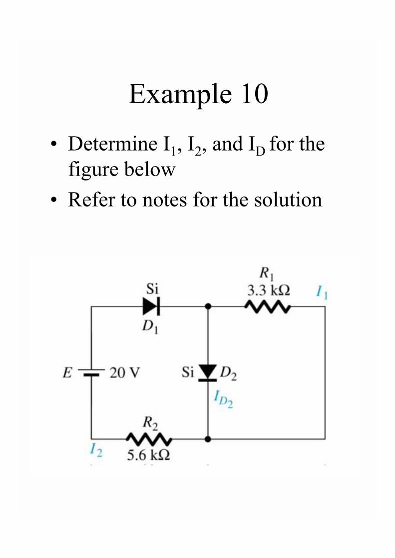
� Determine I1, I2, and ID for the figure below
� Refer to notes for the solution
Example 10
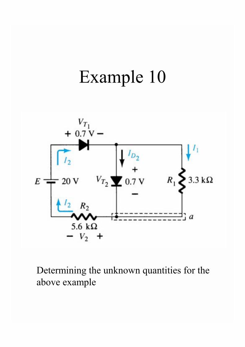
Example 10
Determining the unknown quantities for the above example

Sinusoidal Inputs:Half-wave Rectifier
� We expand our analysis to include time varying signals
� Such a network is shown as in the next figure
� This circuit is called half-wave rectifier
� For the positive and negative cycles, the circuit is approximated as in below
� See following 2 figures

Half-wave Rectifier


Half-wave Rectifier
� The total effect of diode on the output signal is given in below

Half-wave Rectifier
� For the half-wave rectified signal:
Vdc = 0.318 Vm
� If the effect of VT is also considered, the output of the system will as below
� Vdc = 0.318 (Vm- VT)� See next Figure

Effect of VT on half-wave rectified signal

PIV rating of Half-wave Rectifiers
� PIV rating is very important consideration for rectifier circuits
� For the half-wave rectifier:� PIV ≥ Vm

Full-wave RectifiersBridge Networks
� The dc level obtained from a sinusoidal input to the half-wave rectifier can be improved to 100% using full wave rectifiers
� Bridge networks are used for this purpose
� See Figure 2.54� For positive and negative
cycles, network acts as below � See Figures 2.55 � 2.58