“bridge in a backpack” inflatable bridge‐in‐a‐backpack” inflatable...
TRANSCRIPT

“Bridge‐in‐a‐Backpack”Inflatable Composite ConcreteInflatable Composite‐Concrete
Bridges
Dr. H. J. Dagher, P.E.Director, AEWC Advanced Structures and Composites Center
University of Maine

OutlineOutline
• UMaine Composites Center
• Governor’s Composites Initiative
• Bridge‐in‐a‐Backpack• Bridge‐in‐a‐Backpack– Why and how
8 Years of R&D– 8 Years of R&D
– 2 demonstration projects
f d• Benefits and next steps
• Video
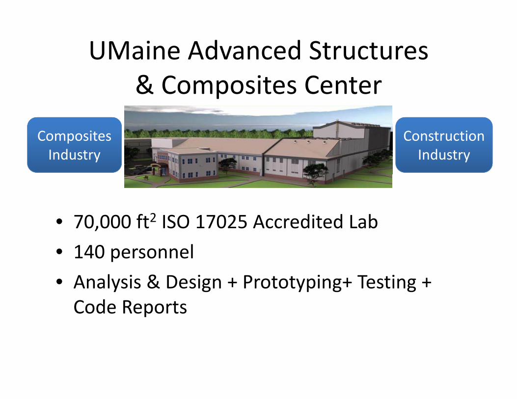
UMaine Advanced Structures& Composites Center
Composites Industry
Construction Industry
• 70 000 ft2 ISO 17025 Accredited Lab70,000 ft ISO 17025 Accredited Lab
• 140 personnel
A l i & i i i• Analysis & Design + Prototyping+ Testing + Code Reports
UMaine Composites CenterUMaine Composites Center
• 200+ Clients Globally
• Prototyping/testing up to 230 ft spans
• Nanocomposites• Nanocomposites
• Global Impactd l– 3 ACMA ACE awards in last 2 years
– 2009 Champion for Economic Development Award
– Over 400 publications in last 10 years

Maine’s Composites InitiativeMaine s Composites Initiative
• Governor John Baldacci
• Up to 10% composites for bridgesUp to 10% composites for bridges
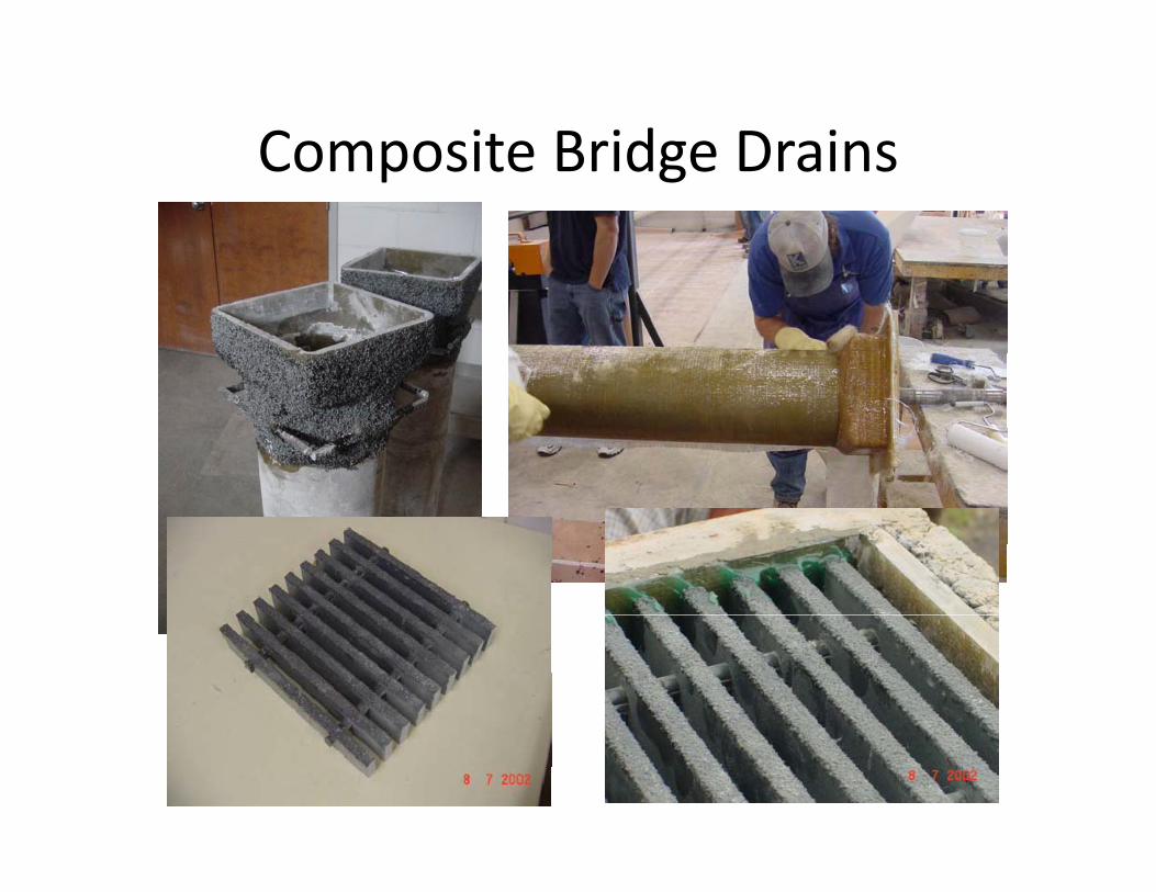
Composite Bridge DrainsComposite Bridge Drains

Maine DOT Collaboration
• Hillman Composite Beam• Hillman Composite Beam– Static and fatigue testing
00 f b id d– 500 ft bridge under contract
• Composite Culvert LiningLining– Composite liner repairs degraded metal culvertsdegraded metal culverts

Penobscot Narrows Bridge
CFRP Strands
• Maine DOT, FHWA, Figg Engineering Group, UMaine• Steel strands replaced with carbon composite strands• Long term performance monitoring
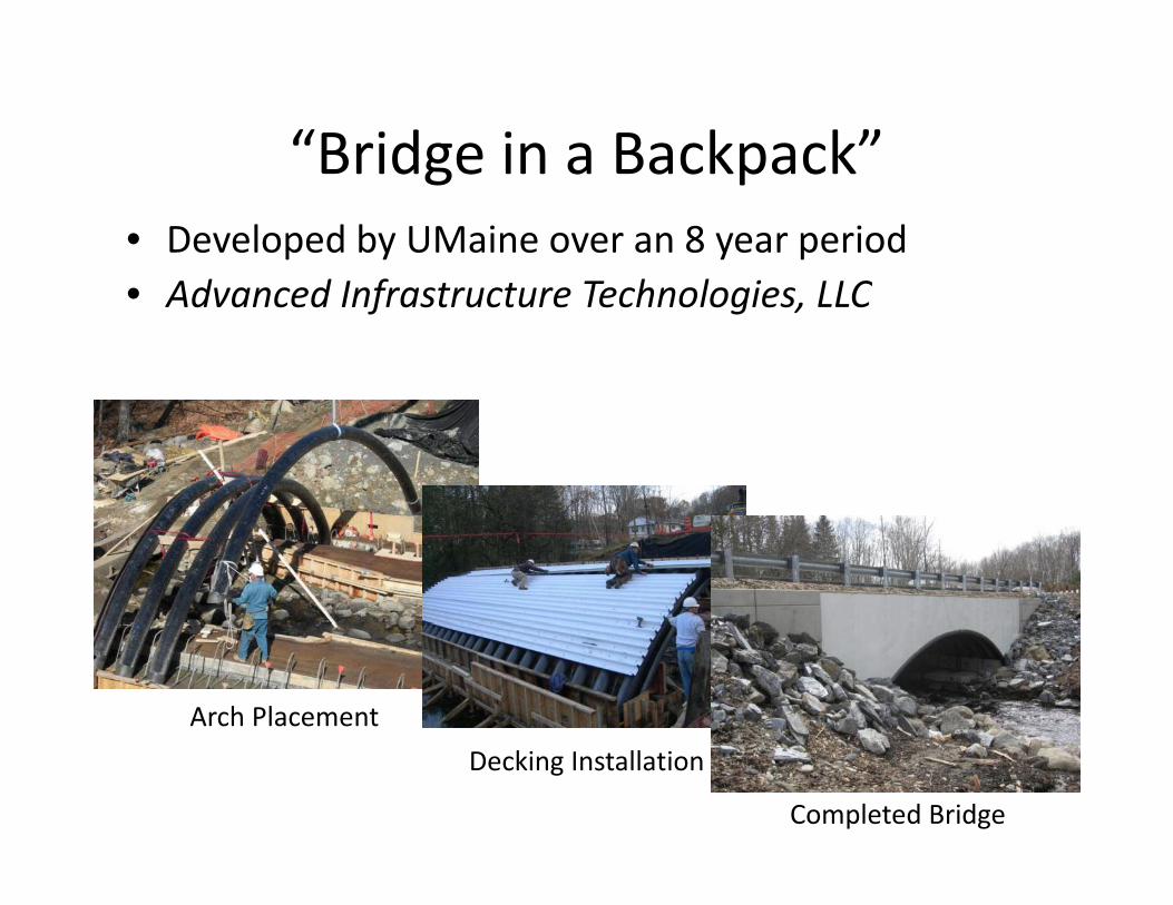
“Bridge in a Backpack”Bridge in a Backpack• Developed by UMaine over an 8 year periodAd d I f T h l i LLC• Advanced Infrastructure Technologies, LLC
Arch Placement
Decking Installation
Completed Bridge

On‐Site Production: d h d h dl lReduce shipping and handling logistics
A h F kArch Formwork
• Geometries completely customizable for site requirements• Spans made up to 90’, tube thickness up to ½”
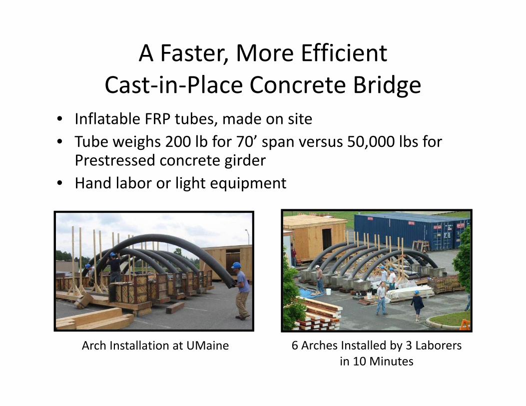
A Faster, More Efficientl dCast‐in‐Place Concrete Bridge
• Inflatable FRP tubes, made on site,• Tube weighs 200 lb for 70’ span versus 50,000 lbs for
Prestressed concrete girderH d l b li h i• Hand labor or light equipment
6 Arches Installed by 3 Laborers in 10 Minutes
Arch Installation at UMaine
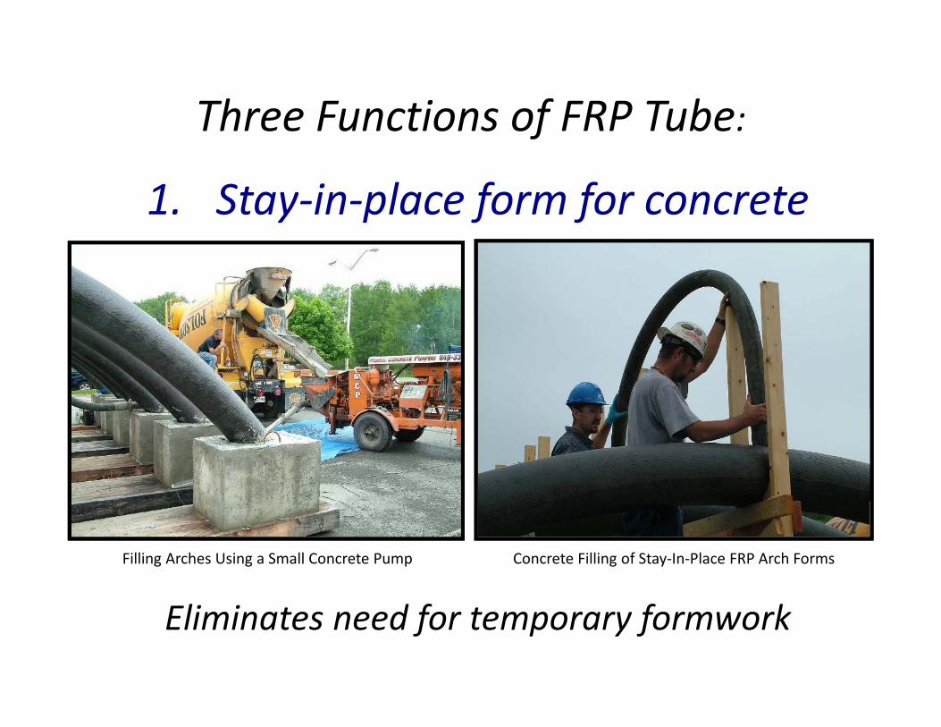
Three Functions of FRP Tube:f
1. Stay‐in‐place form for concrete
Concrete Filling of Stay‐In‐Place FRP Arch FormsFilling Arches Using a Small Concrete Pump
Eliminates need for temporary formwork
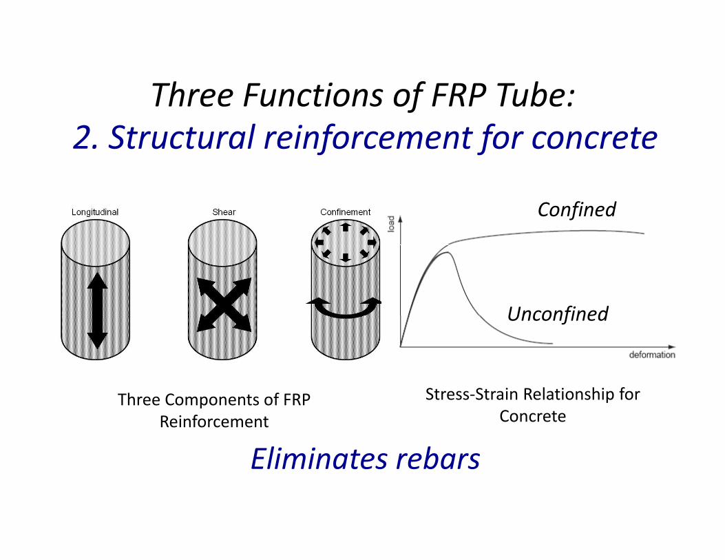
Three Functions of FRP Tube:Three Functions of FRP Tube:2. Structural reinforcement for concrete
Confined
UnconfinedUnconfined
Eliminates rebars
Three Components of FRP Reinforcement
Stress‐Strain Relationship for Concrete
Eliminates rebars
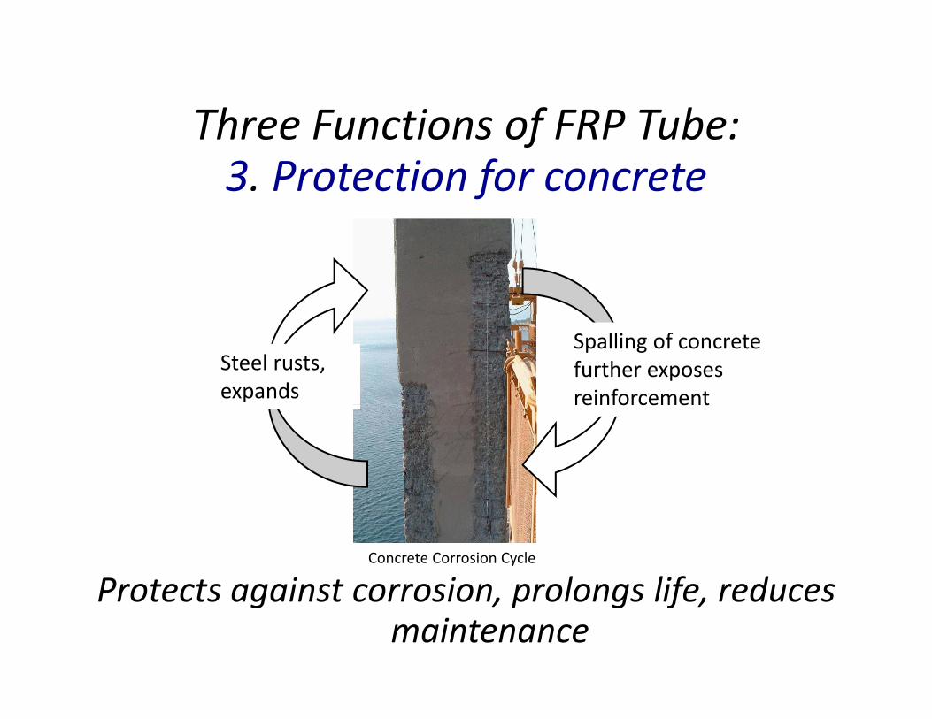
Three Functions of FRP Tube:Three Functions of FRP Tube:3. Protection for concrete
Steel rusts, expands
Spalling of concrete further exposes reinforcemente o ce e t
Protects against corrosion prolongs life reducesConcrete Corrosion Cycle
Protects against corrosion, prolongs life, reduces maintenance

8 Years of Design & Testing at UMaine8 Years of Design & Testing at UMaine
Hydraulic Actuator
Arch Specimen
DIC Targets
Concrete End Support Block
Static & fatigue testing f 40 i
Simple Support
of over 40 specimens

Experimental and Predicted ResponseArch Deflected Shape, Experimental and Predicted
(Deflections Magnified 15X)30
P
10
10
P
DIC Targets
-30
-10
atio
n (in
)
-70
-50Loca
P di t d
-110
-90
PredictedExperimental
-140 -120 -100 -80 -60 -40 -20 0 20 40 60 80 100 120 140
Location (in)

Experimental and Predicted Responsep p
Load (kip) COV specimens Difference( p) p
InitialExperimental 72.0 2.55% 3
4.14%Predicted 69.0 ‐‐‐‐‐‐‐‐ ‐‐‐‐‐‐‐‐
SecondaryExperimental 57.6 7.75% 3
1.10%Predicted 57.0 ‐‐‐‐‐‐‐‐ ‐‐‐‐‐‐‐‐
Load-Deflection Response of Concrete-Filled FRP Tubular Arch
60
70
80
)
Initial hinge at crown
20
30
40
50
App
lied
Load
(kip
Subsequent 0
10
0 1 2 3 4 5 6 7 8 9 10
Vertical Deflection at Crown (in)
Initial Static Test to Failure Post-Failure Behavior
qhinges at shouldersl

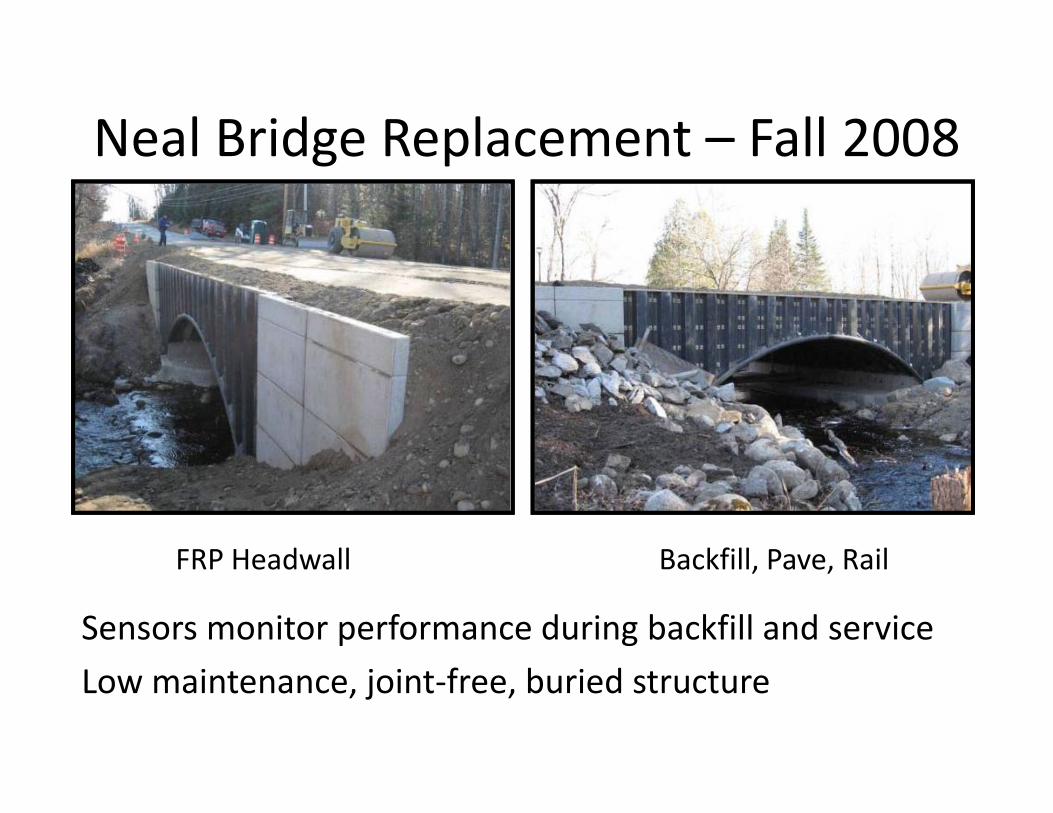
Neal Bridge Replacement – Fall 2008
• First Bridge‐in‐a‐Backpack, 34’ span, 44’ wide
• 23 arches installed in one day
• Arches filled with concrete (1 hour)
• FRP decking
Neal Bridge Replacement – Fall 2008Neal Bridge Replacement Fall 2008
FRP Headwall Backfill Pave Rail
Sensors monitor performance during backfill and service
FRP Headwall Backfill, Pave, Rail
Low maintenance, joint‐free, buried structure

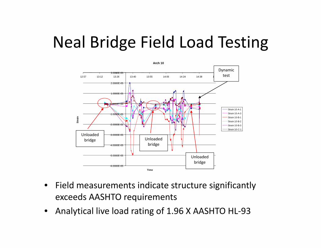
Neal Bridge Field Load TestingNeal Bridge Field Load Testing
• Performed April 2009• 2 fully loaded tandem axle dump trucks (66 kip total weight)total weight)
• Loading configurations in parallel and series, quasi static and dynamicquasi‐static and dynamic
• Instrumentation:– Arches – strain and
Soil Pressure Gages
deflection– Soil – vertical and radial soil pressure Strain & Deflection Gages
Neal Bridge Field Load TestingNeal Bridge Field Load Testing
3.0000E-0512:57 13:12 13:26 13:40 13:55 14:09 14:24 14:38 14:52
Arch 10
Dynamic test
0.0000E+00
1.0000E-05
2.0000E-05
12:57 13:12 13:26 13:40 13:55 14:09 14:24 14:38 14:52
-3.0000E-05
-2.0000E-05
-1.0000E-05
Str
ain
Strain 10-A-1
Strain 10-A-3
Strain 10-B-1
Strain 10-B-2
Strain 10-B-3
Strain 10-C-1
Unloaded bridge Unloaded
-6.0000E-05
-5.0000E-05
-4.0000E-05
Time
bridge Unloaded bridge
Unloaded bridge
• Field measurements indicate structure significantly exceeds AASHTO requirements
• Analytical live load rating of 1.96 X AASHTO HL‐93

McGee Bridge Replacementg p• Composite low bid against Steel, Concrete, and Wood
• August 2009: installation in North Anson ME• August 2009: installation in North Anson, ME
Bid # Bridge Type % Over Low Bid
1 Bridge‐in‐a‐ ‐‐‐1 Bridge in aBackpack
2 Steel on concrete 6.8%
3 St l t 18 4%3 Steel on concrete 18.4%
4 Steel on concrete 23.4%
5 Concrete 23.5%
6 Timber on concrete 30.0%
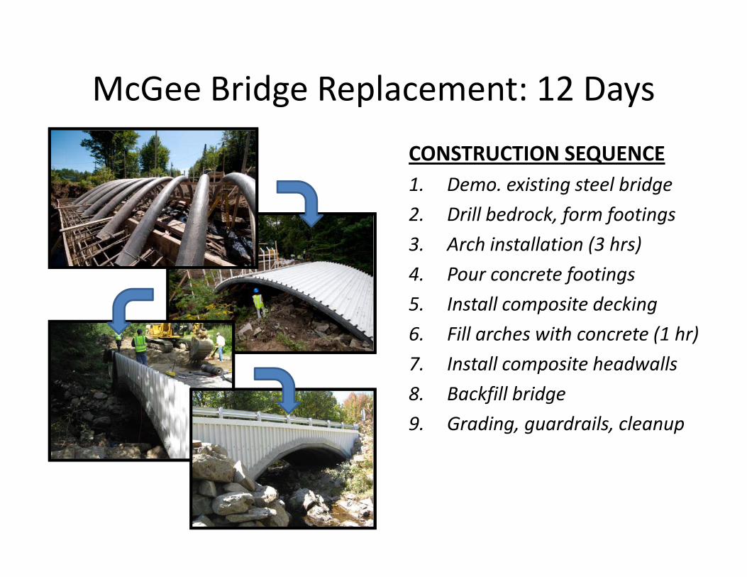
McGee Bridge Replacement: 12 Daysg p y
CONSTRUCTION SEQUENCE1 D i ti t l b id1. Demo. existing steel bridge
2. Drill bedrock, form footings
3. Arch installation (3 hrs)( )
4. Pour concrete footings
5. Install composite decking
6. Fill arches with concrete (1 hr)
7. Install composite headwalls
8 Backfill bridge8. Backfill bridge
9. Grading, guardrails, cleanup

Where we’re goingWhere we re going…

2010‐2011 Governor’s Composite dBridge Construction
• 5 more Maine bridges in 2 years• 5 more Maine bridges in 2 years
• Spans from 24’ – 72’
• Currently in design phaseCurrently in design phase
1
12
2 32
3
4
45
56 6

Continuing R&D PlanContinuing R&D Plan
Expand Geometric Capabilities
• Spans up to 90 ft
• Diameters up to 26”
• Rigid frame and girder designs
d f i bili iExpand Manufacturing Capabilities
• Onsite manufacturing
• Versatile resin packageVersatile resin package
• Large scale production

Bridge‐in‐a‐Backpack Capabilities:Interstate OverpassInterstate Overpass

Bridge‐in‐a‐Backpack Capabilities:Stream Crossings/Railway CrossingsStream Crossings/Railway Crossings
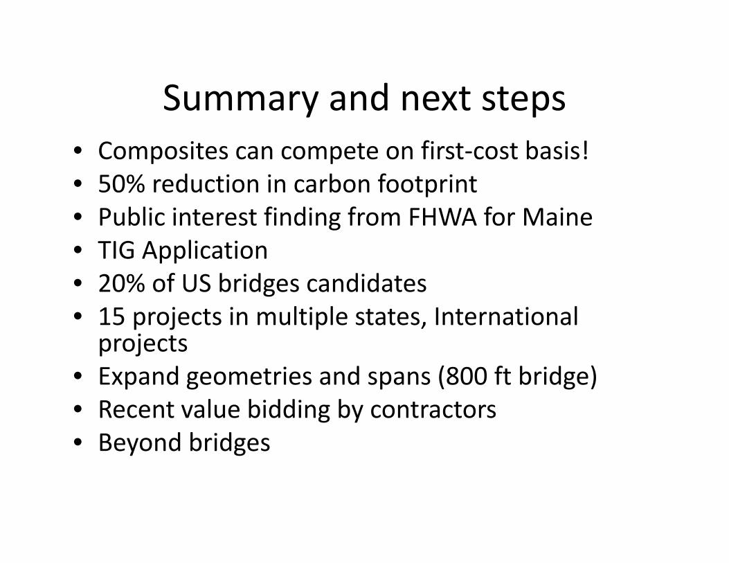
Summary and next stepsSummary and next steps• Composites can compete on first‐cost basis!50% d i i b f i• 50% reduction in carbon footprint
• Public interest finding from FHWA for Maine• TIG Application• TIG Application• 20% of US bridges candidates• 15 projects in multiple states International• 15 projects in multiple states, International projects
• Expand geometries and spans (800 ft bridge)p g p ( g )• Recent value bidding by contractors• Beyond bridges

Th k !Thank you!
Contact:
Dr. Dagher, P.E., Directorg , ,
Advanced Structures and Composites Center
University of MaineUniversity of Maine
(207) 581‐2138