aluminum hardtop gazebo assembly instructions … instructions ltem: aluminum hardtop gazebo model:...
TRANSCRIPT
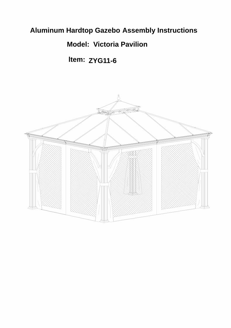
Assembly Instructions
ltem:
Aluminum Hardtop Gazebo
Model: Victoria Pavilion
ZYG11-6

P1
ALUMINUM HARDTOP GAZEBO ASSEMBLY INSTRUCTION
Note:THIS UNIT IS HEAVY! For safety, Do NOT assemble this item alone. six people are recommended for a safe assembly. A screw driver, hammer, two ladders (not included) with height no less than
2.5m are needed to install. For ease of identification when installing, all parts are labeled. This product takes at least two hours to set up. When unpacking the product, please discard the metal
, protecting frames included in the shipping cartons.
e part is used.
Step.3
Step.2
Step.4
Step.1
Step.5
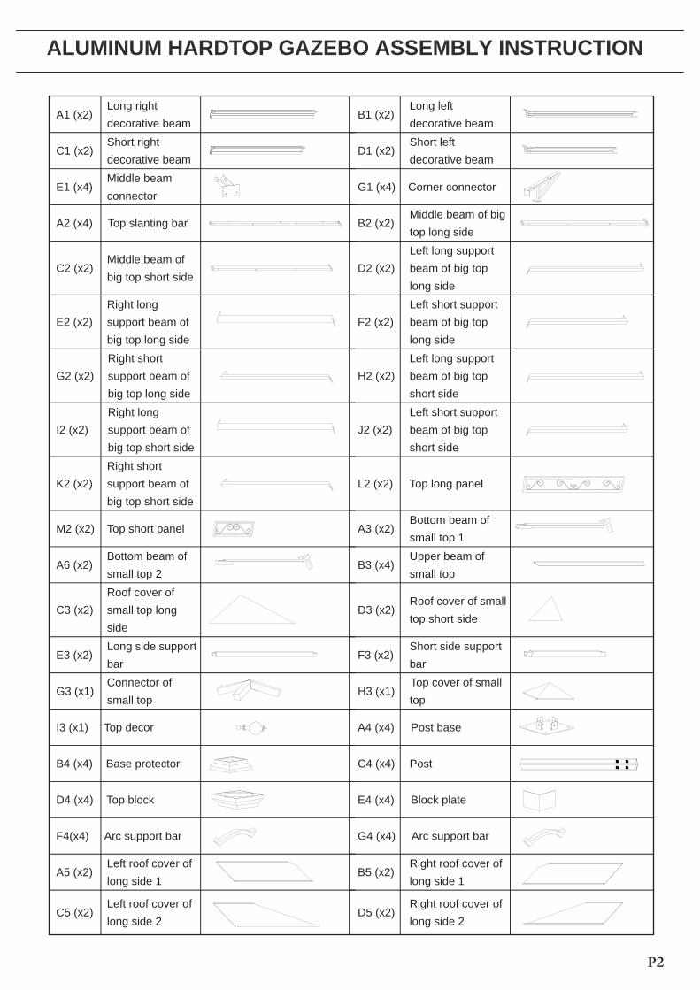
A1 (x2) Long right decorative beam
B1 (x2)Long left decorative beam
C1 (x2) Short right decorative beam
D1 (x2)Short left decorative beam
E1 (x4) Middle beam connector
G1 (x4) Corner connector
A2 (x4) Top slanting bar B2 (x2)Middle beam of big top long side
C2 (x2) Middle beam of big top short side
D2 (x2)Left long support beam of big top long side
E2 (x2) Right long support beam of big top long side
F2 (x2)Left short support beam of big top long side
G2 (x2) Right short support beam of big top long side
H2 (x2)Left long support beam of big top short side
I2 (x2) Right long support beam of big top short side
J2 (x2)Left short support beam of big top short side
K2 (x2) Right short support beam of big top short side
L2 (x2) Top long panel
M2 (x2) Top short panel
A3 (x2) Bottom beam of small top 1
A6 (x2) Bottom beam of small top 2
B3 (x4) Upper beam of small top
C3 (x2) Roof cover of small top long side
D3 (x2)Roof cover of small top short side
E3 (x2) Long side support bar
F3 (x2)Short side support bar
G3 (x1) Connector of small top
H3 (x1)Top cover of small top
I3 (x1) Top decor A4 (x4) Post base
B4 (x4) Base protector C4 (x4) Post
D4 (x4) Top block E4 (x4) Block plate
F4(x4) Arc support bar G4 (x4) Arc support bar
A5 (x2) Left roof cover of long side 1
B5 (x2)Right roof cover of long side 1
C5 (x2) Left roof cover of long side 2
D5 (x2)Right roof cover of long side 2
P2
ALUMINUM HARDTOP GAZEBO ASSEMBLY INSTRUCTION
P3
E5
(x2) Left
roof
cover
of long
side
3 F5
(x2)Right
roof
cover
of long
side
3
G5
(x2) Roof
cover
of
short
side
1 H5
(x2)Left
roof
cover
of Short
side
2
I5 (x2) Right
roof
cover of
short
side
2 J5
(x2)
Left
roof
cover
of Short
side
3
K5 (x2) Right
roof
cover of
short
side
3 L5
(x4)
Top
cover
M5
(x1)
Pothook N5 (x18) Roof press sheet
Hardware Pack
1
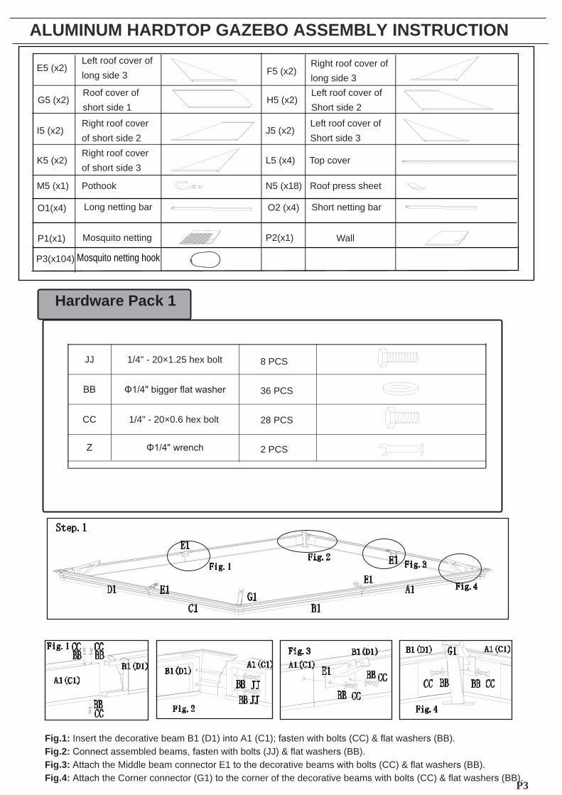
JJ
1/4" - 20×1.25
hex bolt
CC
1/4" -
20×0.6
hex bolt
8 PCS
36 PCS
28 PCS
2 PCS
Fig.1: Insert the decorative beam B1 (D1) into A1 (C1); fasten with bolts (CC) & flat washers (BB).Fig.2: Connect assembled beams, fasten with bolts (JJ) & flat washers (BB). Fig.3: Attach the Middle beam connector E1 to the decorative beams with bolts (CC) & flat washers (BB). Fig.4: Attach the Corner connector (G1) to the corner of the decorative beams with bolts (CC) & flat washers (BB).
Long netting
bar
O1(x4) Short
netting
bar
O2 (x4)
Wall P2(x1)
P1(x1)
ALUMINUM HARDTOP GAZEBO ASSEMBLY INSTRUCTION
P3(x104) Mosquito netting hook
Mosquito netting
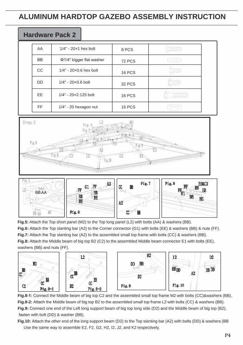
AA 1/4" - 20×1 hex bolt 8 PCS
72 PCS
16 PCS
32 PCS
16 PCS
16 PCS
CC 1/4" - 20×0.6 hex bolt
DD 1/4" - 20×0.6 bolt
EE 1/4" - 20×2.125 bolt
FF 1/4" - 20 hexagon nut
Hardware Pack 2
Fig.5: Attach the Top short panel (M2) to the Top long panel (L2) with bolts (AA) & washers (BB). Fig.6: Attach the Top slanting bar (A2) to the Corner connector (G1) with bolts (EE) & washers (BB) & nuts (FF). Fig.7: Attach the Top slanting bar (A2) to the assembled small top frame with bolts (CC) & washers (BB). Fig.8: Attach the Middle beam of big top B2 (C2) to the assembled Middle beam connector E1 with bolts (EE), washers (BB) and nuts (FF).
Fig.8-1: Connect the Middle beam of big top C2 and the assembled small top frame M2 with bolts (CC)&washers (BB).Fig.8-2: Attach the Middle beam of big top B2 to the assembled small top frame L2 with bolts (CC) & washers (BB).Fig.9: Connect one end of the Left long support beam of big top long side (D2) and the Middle beam of big top (B2), fasten with bolt (DD) & washer (BB). Fig.10: Attach the other end of the long support beam (D2) to the Top slanting bar (A2) with bolts (DD) & washers (BB
Use the same way to assemble E2, F2, G2, H2, I2, J2, and K2 respectively.
P4
ALUMINUM HARDTOP GAZEBO ASSEMBLY INSTRUCTION
BB AA
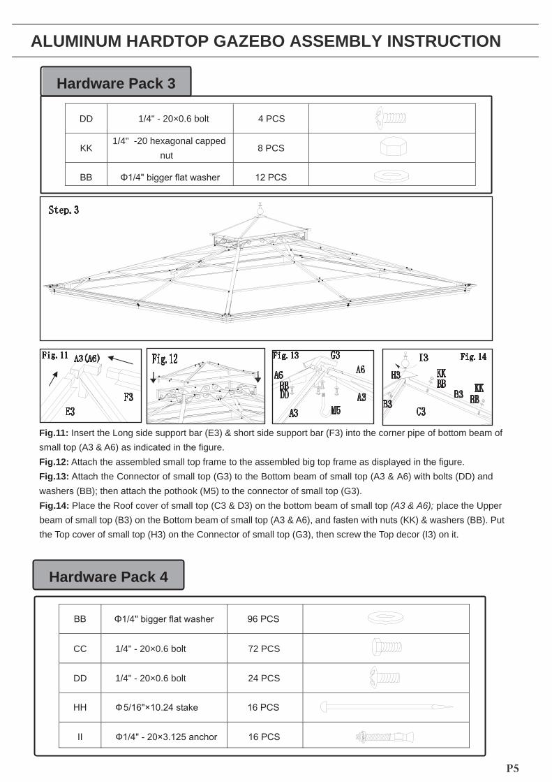
Fig.11: Insert the Long side support bar (E3) & short side support bar (F3) into the corner pipe of bottom beam of small top (A3 & A6) as indicated in the figure. Fig.12: Attach the assembled small top frame to the assembled big top frame as displayed in the figure. Fig.13: Attach the Connector of small top (G3) to the Bottom beam of small top (A3 & A6) with bolts (DD) and washers (BB); then attach the pothook (M5) to the connector of small top (G3). Fig.14: beam of small top (B3) on the Bottom beam of small top (A3 & A6), and fasten with nuts (KK) & washers (BB). Put the Top cover of small top (H3) on the Connector of small top (G3), then screw the Top decor (I3) on it.
Hardware Pack 4
CC 1/4" - 20×0.6 bolt 72 PCS
DD 1/4" - 20×0.6 bolt 24 PCS
P5
Hardware Pack 3
DD 1/4" - 20×0.6 bolt 4 PCS
KK 1/4" -20 hexagonal capped
nut 8 PCS
ALUMINUM HARDTOP GAZEBO ASSEMBLY INSTRUCTION
Place the Roof cover of small top (C3 & D3) on the bottom beam of small top place the Upper(A3 & A6);

Fig.15: Lift the Base protector (B4), attach the post base (A4) to the post (C4) with bolts (DD) & washers (BB). Fig.16: Attach the top block (D4) to the post (C4) with bolts (CC) & washers (BB). (Note: the screw holes on the post and the screw holds for installing the block plate (E4) should be in the same direction as shown in the figure) Fig.17: Lift the assembled pavilion roof and attach the assembled posts to the corners of the roof with bolts(CC) & washers (BB). (Note: The screw holes on the post must be directed inward. 6 people are needed here.) Fig.18: Attach the Corner connector (G1) to the top block (D4) with bolts (CC) & washers (BB).
Fig.19: Attach the block plate (E4) to the top block (D4) with bolts (DD) & washers (BB). Fig.20: Attach the arc support bar (F4/G4) to the post (C4) & decorative beam with bolts (CC) & washers (BB). Fig.21: If placing the gazebo on soft ground, use ground stakes (HH) for added stability. Fig.21-1: If placing the gazebo on the cement ground, fasten with concrete anchors (II).
P6
ALUMINUM HARDTOP GAZEBO ASSEMBLY INSTRUCTION
Fig.15 B4 A4
B4 A4
C4
G4D4
Fig.20
F4G4
D4
C4 C4
Fig.21 Fig.21-1
F4Fig.16
Fig.17
D4
Fig.18Fig.19
Hardware Pack 5
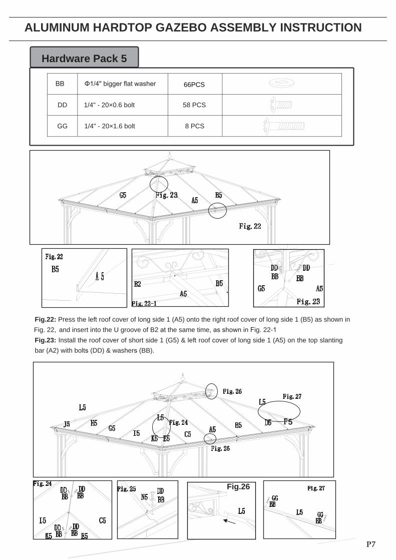
Fig.22: Press the left roof cover of long side 1 (A5) onto the right roof cover of long side 1 (B5) as shown in Fig. 22, and insert into the U groove of B2 at the same time, as shown in Fig. 22-1 Fig.23: Install the roof cover of short side 1 (G5) & left roof cover of long side 1 (A5) on the top slanting bar (A2) with bolts (DD) & washers (BB).
DD 1/4" - 20×0.6 bolt 58 PCS
GG 1/4" - 20×1.6 bolt 8 PCS
P7
ALUMINUM HARDTOP GAZEBO ASSEMBLY INSTRUCTION
5
Fig.26
66PCS
IMPORTANT:1.
Keep
all
children
and
pets
away
from
assembly
area.
Children
and
pets
should
be
supervised
when
they
are
in the
area
of
pavilion
construction. 2.
The
area
for
assembly
should
not
be
less
than
6
feet
from
any
obstruction
such
as
fence,
garage,
house, overhanging
branches,
laundry
line
or
electrical
wires.
3.
This
unit
is
heavy.
Do
not
assemble
this
item
alone,
six people
are
recommended
for
safe
assembly. 4.
Some
parts
may
contain
sharp
edges.
Wear
protective
gloves
if
necessary
during
assembly. 5.
When
assembling
and
using
this
product,
basic
safety
precautions
should
always
be
followed
to
reduce
the
risk of
personal
injury
and
damage
to
equipment.
Please
read
all
instructions
before
assembly
and
use. 6.
For
outdoor
use
only.
Install
on
level
ground.
16
stakes
are
provided
to
secure
the
pavilion
in
the
ground.
If
you wish
to
secure
the
pavilion
to
a
wood
deck
surface,
you
will
need
to
purchase
fasteners
appropriate
for
these
surfaces.
These
are
readily
available
at
your
local
hardware
store
or
home
center.
7.
Check
all
bolts
for
tightness
before
and
during
usage.
8. Please check your state and local
regulations
prior
to
purchasing. Some
jurisdictions
may
require
permits
for,
or otherwise
regulate,
installation
and
use.
9.
While
this
pavilion
is
manufactured
to
withstand
gale
force
winds
utilizing
only
the
supplied
ground
stakes,
in
areas
subject
to
frequent
severe
weather,
securing
the
pavilion
to
a
deck,
concrete
patio
or
footings
should
be
considered.
10.
Your
pavilion
has
been
engineered
to
accommodate
winter
snow
loads
incurred
in
most
areas.
Removal
of accumulated
snow
on
the
pavilion
roof
with
a
roof
rake
is
recommended.
In
areas
that
are
regularly
subject
to
blizzard
conditions
however,
removal
of
the
roof
panel
is
suggested.
The
assembled
roof
structure
can
simply
be
left
intact
until
warmer
conditions
return.
Fig.24: Attach the
roof
covers
C5,
D5,
E5,
F5,
H5,
I5,
J5,
K5
to
the
top
slanting
bar
(A2)
with
bolts
(DD)
& washers
(BB).
Fig.25: Press up
the
roof
cover
with
the
roof
press
sheet
(N5),
and
fix
N5
on
the
decorative
beam
with
bolt (DD)
& washer
(BB).
Fig.26: Insert the
top
cover
(L5)
into
the
hole
of
the
small
top
frame
corner.
Fix the
top
cover
(L5)
on
the
top
slanting
bar
(A2)
with
bolts
(GG)
& washers
(BB).
P8
ALUMINUM HARDTOP GAZEBO ASSEMBLY INSTRUCTION
Now, your Sunoma Pavilion is ready for use.
Fig.28
Fig.29
Fig.27:
Fig.28: :
DDDD
DD
DD
BB
BB
BB
BB
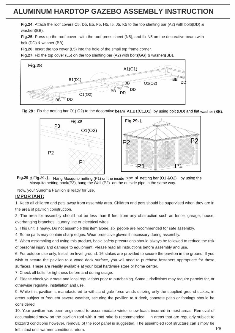
Fix the netting bar O1( O2) to the decorative washer (BB). beam A1,B1(C1,D1) by using bolt (DD) and flat
A1(C1)
B1(D1)O1(O2)
O1(O2)
Fig.29 Hang Mosquito netting (P1) on the inside netting bar (O1 &O2) by using the pipe of on the outside pipe in the same way. Mosquito netting hook (P3), hang the Wall (P2)
P1P1
P2P2
Fig.29 -1
& Fig.29 -1 :
P3O1(O2)
P2
P1
P9
ALUMINUM HARDTOP GAZEBO ASSEMBLY INSTRUCTION
CUSTOMER SERVICE Zenith Industries, LCC warrants to the original purchaser that this item is free from defects in work-manship and materials of your item provided the item was factory-sealed at the time of purchase and is maintained with care and used only for personal, residential purposes. The item is warranted to be free from defects in material or workmanship for a period of 1 year. Should any manufacturing defect arise within this warranty period, Zenith Industries, LLC will repair or replace (at our option) any defective merchandise upon proof of purchase receipt with date at no charge to the customers for replace parts and labor; however, transportation and delivery costs, remain the responsibility of the purchaser. A purchaser of an "open box," previously-returned, or "clearance" item, as well as original purchasers outside of the warranty period, may obtain replacement parts from Zenith Industries forproducts in current production, at nominal cost.
If you are within the return policy that most stores have, you do have the option of returning this item back to the store which you bought it from for an exchange of the same item, or a refund of the purchase.
If you are within or beyond the return policy that most stores have, and need tech. assistance or replacement parts, please call Zenith Industries, LLC at 1(855)-6-ZENITH from 9:30 am to 6:30 pm eastern standard time or e-mail to [email protected] or fax your parts replacement order form together with the purchase receipt to 1 (513) 217-9415 for assistance.
CARE & Maintenance Our steel components for garden accessories and furniture are treated with rust inhibiting paint that protects it from rusting. However, due to the nature of steel, surface oxidation (rusting) will occur once these protective coatings are scratched. This is a natural process and is not a defect! To minimize this condition, we recommend care when assembling & handling the product to prevent scratching the paint. Should any scratching or damage occur, we
Surface rust can also recommend immediate touch-up with rust inhibiting paint. be easily removed with a very light application of common cooking oil. If surface oxidation (rusting) occurs and if no measure is taken to prevent this, the oxidation may start dripping on to deck or patio and caused damaging stains, which may be difficult to remove.
This can be prevented if the measure is taken to keep the product from oxidizing.