pdf vectus prt concept and 420.67 kb 02-05-2013
TRANSCRIPT

VECTUS PRT CONCEPT AND TEST TRACK EXPERIENCE
Jörgen Gustafsson1 and Svante Lennartsson
2
1 Chief Technical Officer, Vectus Ltd, Husargatan 2, S-752 37 Uppsala, Sweden;
[email protected] 2VP Engineering, Vectus Ltd, Husargatan 2, S-752 37 Uppsala, Sweden;
Abstract
PRT, Personal Rapid Transit, is a transportation concept with small vehicles on a
low-weight structure offering a high level of service to its passengers. Vectus, with
operations in Korea and Sweden, is at the forefront of PRT technology. Vectus has
built a test track in Sweden where the system functionality and performance has been
verified. Authority approval has been obtained including a complete safety case. The
test track concept and the key features of the Vectus system are described along with
the current operational experience. This includes two full winter seasons, proving the
system’s capability to cope with various ice and snow conditions. Test activities are
now in the final stages of reliability and endurance testing, verifying the long term
operational aspects of the system.
Introduction
PRT has been discussed as a concept for decades, and extensive research and various
investigations have been done to determine its potential as a transportation system for
tomorrow. Vectus is one of the few systems that has been built and that has
experienced full testing. Vectus is able to fully demonstrate a PRT concept (see
Figure 1) with the following key features:
Flexible mechanical guidance system with:
Vehicles that are captive on the track
Vehicles that are mechanically guided along the track
Vehicles that are mechanically steered through switches
Headway down to 3 seconds, fulfilling brick-wall stop requirement,
also in winter conditions
Top speed about 45 km/h
Asynchronous control system, maintaining highest performance under
all operating conditions

Dynamic moving-block vehicle separation maximizing vehicle flow
and allowing speed restrictions without capacity reductions
Distributed, reliable control with dynamic routing capable of virtually
unlimited expansion
Full winter operability with linear motor technology
Complete and approved safety case
Full RAM and LCC analysis
Vectus has built and operates a test track in Uppsala, Sweden. It has 400 meters (m)
of track, three vehicles and one station. The test track construction started in the
spring of 2006. In December the first trial runs were made with a chassis to verify the
propulsion system and basic controls. The first complete vehicle arrived in the
summer of 2007. Since then, tests and verifications have been made, step by step,
with increasingly more complex functionality to cover all aspects envisaged to be
needed in a commercial application. A thorough design process has been applied,
covering safety, reliability etc., not only for the test track itself, but also for a generic
PRT system. The test track has been approved by the Swedish Rail Agency for
operation with passengers.
Figure 1. First complete vehicle in full operation, summer, 2007
Vectus Test Track
The test track built by Vectus in Uppsala, Sweden is a key component of Vectus PRT
development. Prior to the test track being built, various studies had been conducted
over several years. One important aspect of these studies was the overall control and
the logistics solutions of a real system, which were studied using advanced simulation
tools. Based on these studies, the key parameters for a commercially viable system
were identified. From these system characteristics, the different sub-systems and key
technologies were selected. Again, for selected areas, more studies were conducted in
test rigs, simulators, scaled models, etc. Most of these studies were conducted in
England and Sweden. It is noteworthy that Vectus PRT development did not originate
from a technical concept for e.g. track and vehicle, but rather from a rigorous top-
down process. Development began using the complete system as the main focus with
special considerations for safety and control aspects. Systems and components were
then selected to suit these criteria.
Having these steps accomplished, it was time to build the first full-scale system in
2005. Selection of a suitable site was important; a site where there was availability of
good communications, possibility for testing in winter conditions, internationally
recognized authorities for approval, and complementary university and industrial
structures. The site selection process finally ended with the choice of Uppsala, just
north of Stockholm, Sweden.
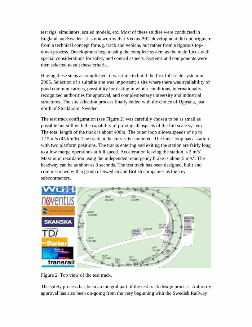
The test track configuration (see Figure 2) was carefully chosen to be as small as
possible but still with the capability of proving all aspects of the full scale system.
The total length of the track is about 400m. The outer loop allows speeds of up to
12.5 m/s (45 km/h). The track in the curves is cambered. The inner loop has a station
with two platform positions. The tracks entering and exiting the station are fairly long
to allow merge operations at full speed. Acceleration leaving the station is 2 m/s2.
Maximum retardation using the independent emergency brake is about 5 m/s2. The
headway can be as short as 3 seconds. The test track has been designed, built and
commissioned with a group of Swedish and British companies as the key
subcontractors.
Figure 2. Top view of the test track.
The safety process has been an integral part of the test track design process. Authority
approval has also been on-going from the very beginning with the Swedish Railway

Authority, with the same set-up and general requirements as are applied when e.g.,
building a new metro (subway).
The detailed planning for the selected site in Uppsala started in late autumn, 2005. In
April 2006 the ground-breaking ceremony was held, and then the first track sections
were delivered in August. Running tests with only a chassis vehicle started in
December, 2006 and the first run around the outer loop was accomplished just before
Christmas. In the spring of 2007 the inner loop and the station were finalized. The
first complete vehicle arrived on-site in the summer of 2007 and the second vehicle
arrived shortly afterwards. The system was displayed for a larger audience at the PRT
seminars held in Uppsala in the autumn of 2007.
Finalization of the commissioning, safety case, and various testing led to an approval
of the safety case in December, 2007, approval for test runs with visitors in March,
2008, and full approval with multiple vehicles and third party passengers in
September, 2008.
The test track is a complete and genuine representation of a full scale PRT-system, in
particular the function of the control system. The vehicles have been given a realistic
design for the look and feel of a real application, whereas the track and parts of the
electrical installations have been selected for ease of testing and quick installation
rather than from an aesthetic point of view (see Figure 3).
Figure 3. Test track with three vehicles and sample 2-berth station.
The main purpose of the test track is to verify the technical design, and particularly
the control aspects. It also makes it possible to carry out a complete safety case
including verification and validation on a real application. Another key aspect has
been the authority process itself, to identify the “real” requirements for all aspects of
a system. There has been ample thought given to various passenger aspects, such as
access for the disabled and guidance for the visually impaired. There is an example of
a ticketing system, and complete passenger interfaces in the vehicles with displays,
intercom, etc.
Another objective is to determine long-term performance. Detailed modeling of the
reliability and availability and life-cycle cost were part of the design process, which
requires verification. The test track also provides a proving ground for continued
development, both for Vectus internal R&D as well as being able to test client-
specific modifications at an early stage.
The Vehicle
The vehicle for the test track was designed to give a realistic impression of form,
shape, and function. It has low weight and high rigidity. It is vandal resistant, easy to
clean, maintain, and repair with no sharp corners or edges. The cabin’s interior design
is determined by safety requirements and complies with European disability
discrimination and accessibility legislation. The layout of seating, grab handles and
control devices follows recommended ergonomic practices for mass transit vehicles.
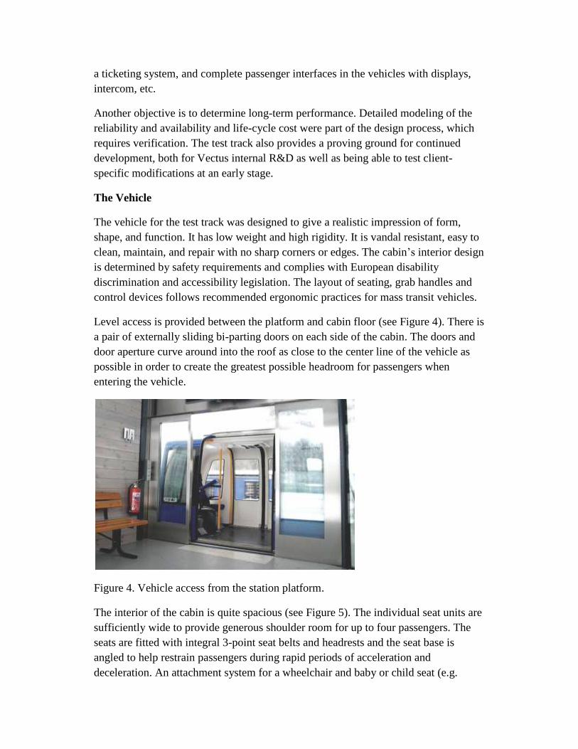
Level access is provided between the platform and cabin floor (see Figure 4). There is
a pair of externally sliding bi-parting doors on each side of the cabin. The doors and
door aperture curve around into the roof as close to the center line of the vehicle as
possible in order to create the greatest possible headroom for passengers when
entering the vehicle.
Figure 4. Vehicle access from the station platform.
The interior of the cabin is quite spacious (see Figure 5). The individual seat units are
sufficiently wide to provide generous shoulder room for up to four passengers. The
seats are fitted with integral 3-point seat belts and headrests and the seat base is
angled to help restrain passengers during rapid periods of acceleration and
deceleration. An attachment system for a wheelchair and baby or child seat (e.g.

between the two adult seats) can be provided.
Interior styling will be developed according to
customer specifications.
LED reading lights are available for each
passenger which can be adjusted individually
with control buttons on the control panel box
located between each pair of seats. The control
panel box incorporates illuminated disability-
compliant push-buttons taken from public
transport standard components. The panel also
incorporates the vehicle’s door control button and
alarm call button that activates communication
with the system operator. An LCD display/touch
screen can also be incorporated for passenger
information and entertainment system. The
interior temperature is thermostatically controlled
with an HVAC (heating, ventilation and air
conditioning) unit which can also be adjusted by
the passenger.
A “FeONIC, Whispering Windows” sound system, using advanced
“magnetostrictive” technology, provides passenger audio. This system effectively
uses the whole interior body shell as a loudspeaker.
The chassis’s wheel arrangement and emergency brake system have been designed to
meet operational and safety requirements with a minimum of equipment and with as
low a building height as possible (see Figure 6). Vectus uses hard tires running on
steel track to minimize rolling resistance, giving low energy consumption and less
sensitivity to vehicle weight.
Vectus employs switching wheels in the chassis for directional control in junctions.
One of the safety advantages of mechanical vehicle-based switching is that direction
selection can be made well in advance, before the junction, allowing time for the
activation mechanisms to be secured in position and locked. There is also positive
mechanical guidance and locking between vehicle and track throughout the whole
junction. There are no moving parts at all in the track.
Effective braking in all conditions is a key function to provide a system with short
headway and still maintain a brick-wall stop requirement. Specially-developed
spring-applied caliper brakes acting directly on the surfaces of the guide rail produce
a constant brake force under all track conditions.
Figure 5. Vehicle interior with
display panel between individual
seats and roof-mounted
ventilation unit.

Figure 6. First chassis tested for clearance on a section of track.
Track
The Vectus design philosophy has been to develop a simple rail and guidance system
independent of the support structure. This allows the architect or system designer the
freedom to develop the type of support structure most suitable for the application.
The track design at the test track was selected primarily for testing purposes. The
guidance system (in blue, see Figure 7) is mounted on a steel support tube as the main
structural component. Only the top portion is required (blue) when being installed
inside a building or in a tunnel, giving a low overall height requirement. A
commercial design may look quite different, while still having the same guidance
concept.
Figure 7. Test track guidance system in blue on steel tube support structure. To the
right above is a possible future design of a track.
The Propulsion System
In order to run with a short headway, and with minimal margins for unwarranted
safety brake applications, precise and consistent performance of the drive system is a
vital component. Linear induction motor (LIM) drives have often been the choice in
various PRT concepts. This is also the case in the Vectus system. Vectus has built its
Typical Track Section
own control system to be able to handle
all types of propulsion, and for the test
track the choice fell to an in-track LIM
propulsion solution.
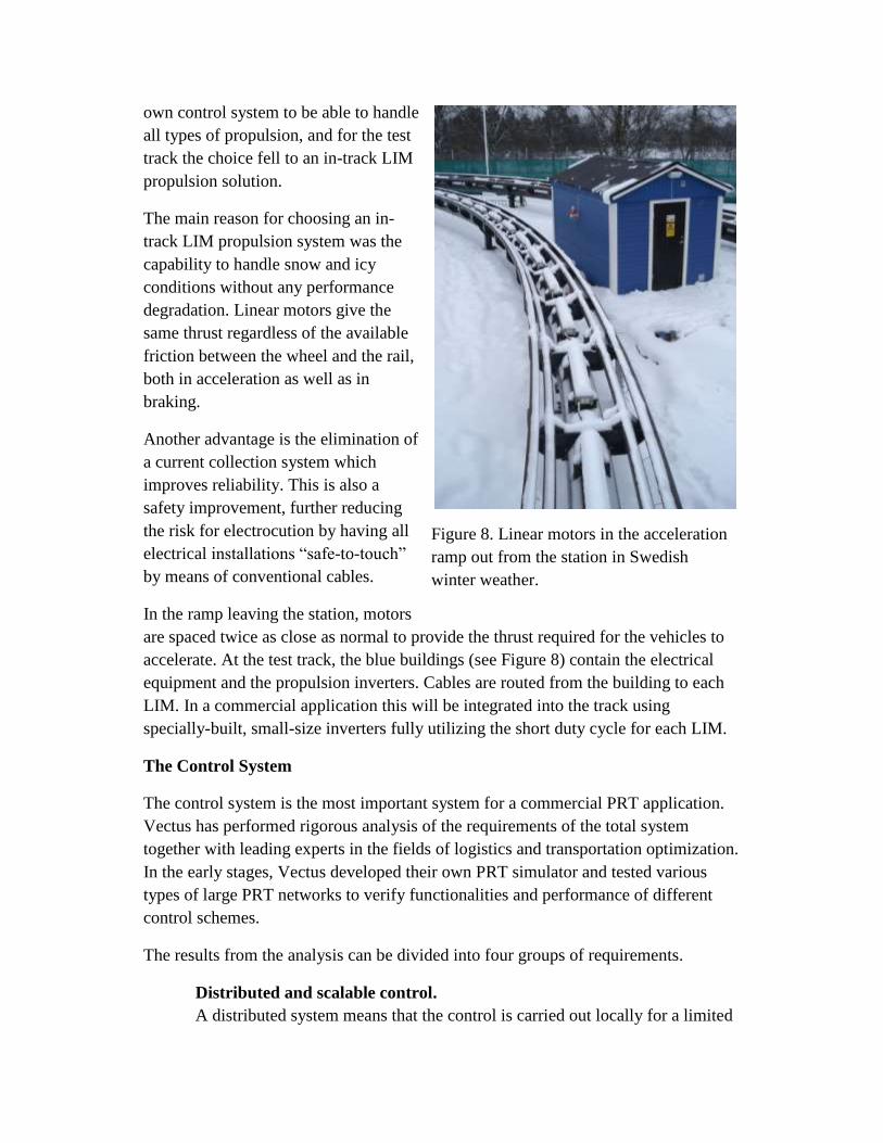
The main reason for choosing an in-
track LIM propulsion system was the
capability to handle snow and icy
conditions without any performance
degradation. Linear motors give the
same thrust regardless of the available
friction between the wheel and the rail,
both in acceleration as well as in
braking.
Another advantage is the elimination of
a current collection system which
improves reliability. This is also a
safety improvement, further reducing
the risk for electrocution by having all
electrical installations “safe-to-touch”
by means of conventional cables.
In the ramp leaving the station, motors
are spaced twice as close as normal to provide the thrust required for the vehicles to
accelerate. At the test track, the blue buildings (see Figure 8) contain the electrical
equipment and the propulsion inverters. Cables are routed from the building to each
LIM. In a commercial application this will be integrated into the track using
specially-built, small-size inverters fully utilizing the short duty cycle for each LIM.
The Control System
The control system is the most important system for a commercial PRT application.
Vectus has performed rigorous analysis of the requirements of the total system
together with leading experts in the fields of logistics and transportation optimization.
In the early stages, Vectus developed their own PRT simulator and tested various
types of large PRT networks to verify functionalities and performance of different
control schemes.
The results from the analysis can be divided into four groups of requirements.
Distributed and scalable control.
A distributed system means that the control is carried out locally for a limited
Figure 8. Linear motors in the acceleration
ramp out from the station in Swedish
winter weather.

part of the system. If there is a fault, it only effects a small part of the system.
The rest of the system will continue to work. With the distributed system there
is no increase in the load for each individual control segment when the system
is expanded.
Asynchronous Control.
With asynchronous control the flow of vehicles is handled as they travel along
their path to their destinations. Merging of vehicles is managed as required on
a local basis. Occasionally there may be a need to slow down to facilitate
merging in switches; there may even be short queues along the route at times.
Travel time may be prolonged by a few seconds, but the overall capacity of
the system is maintained, which is essential to the overall ability to transport
passengers during periods of high system loads (rush hours, events, etc.).
Vehicle Spacing – Dynamic Moving Block.
A moving-block system is superior to any fixed-block vehicle protection
system, even if the fixed blocks are very short. The moving-block system
continuously updates each vehicle with information on the position of the
vehicle in front of it. With this information, each vehicle can run with the
shortest allowed vehicle spacing based on the worst case brake performance.
With a dynamic moving block, the distance between the vehicles can also be
varied depending on the speed of the vehicle (or rather the actual stopping
distance depending on the speed). At lower speeds the vehicles run closer to
each other; at higher speeds the distance is increased. This allows queuing on
the track if required (see Figure 9) without backing up the system for long
distances (the vehicles will stop almost bumper to bumper instead of one in
each fixed block). Most importantly, it enables varying speed along the track,
e.g. in curves, without impacting the flow of the vehicles in that track section,
hence overall capacity of the system remains.
Optimal Control.
The above systems are the building blocks in providing safety, as well as
adequate capacity. Then it is a matter of optimizing the logistics of the
vehicles. Vectus has an adaptive-control which learns from travel patterns of
traffic from previous days. This can be manually altered in the event of e.g.,
delays in a train arriving at one station, special events generating large
crowds, etc. Effective empty vehicle management is another key feature,
reducing the mileage of empty vehicles.

Figure 9. With the dynamic moving block control, vehicles can run with
shorter distance between them at lower speeds.
Safety
The overall safety process in Vectus' PRT project follows the standard EN
50126/IEC62278 "Railway applications – specification and demonstration of
reliability, availability, maintainability and safety (RAMS)”. This is a standard that is
well-implemented in the European Union and defines a process to support the
identification of factors which influence the RAMS of railway systems. This safety
work has been an integral part of Vectus’ development from the beginning.
A number of safety targets were formulated and are as follows:
The safety level for the PRT system shall be better than the safety
levels applicable for competing transport systems such as buses, trams
and taxis.
No single failures in the PRT system shall lead to an accident with
serious consequences.
The PRT system shall be designed so that passengers feel safe and
secure during the whole journey, including their time in the station
areas.
The PRT system shall be built without any serious accidents during
the construction phase.
There shall be no accidents with human injuries during the test phase
of the system.
For the overall PRT system the following risk acceptance criteria was agreed upon
with The Swedish Rail Agency to be met by Vectus (and PRT in general):

Maximum 0.3 fatalities per billion person kilometres for passengers in
PRT system.
A fatality risk of maximum 1·10-6 per year for the most exposed third
person.
For each of the sub-systems, there must be documentation that there
are no single failures that can cause a severe accident.
Safety work has involved various activities such as establishing safety plans and
performing safety analysis, FMECAs (Failure Mode Effect and Criticality Analysis),
fault trees, safety audits, etc. in order to establish a complete safety case. The safety
case was completed in 2007. The required authority approvals to carry passengers
were obtained in the spring of 2008.
Wherever applicable, the safety analysis has not only been done for the test track, “as
built”, but also with considerations for a large, commercial system. The overall safety
targets have been verified for a sample large system by performing a QRA
(Quantitative Risk Assessment).
The QRA includes 78 different sensitivity calculations to verify the criticality of
different input factors. For the larger system that was modeled, passenger risk is
quantified to 0.165 fatalities per billion person kilometers, which is well below the
acceptance criterion of 0.3 fatalities per billion person kilometers.
RAM and LCC
The RAM-process has resulted in the following:
Generation of a qualitative and quantitative model of the PRT system,
modeling the availability and reliability characteristics of all the
components of the system, vehicle, track, station, etc.
Comparison of system RAM characteristics to target values
Contribution to a balanced design by identifying the main factors in
providing adequate availability of the PRT system
Early assessment of needs and possibilities for changes and redesigns
based on a (preliminary) design phase RAM analysis
Follow-up of RAM characteristics during test operation (see Figure
10)
Input for maintenance planning, including definition of a necessary
spare-part inventory

All relevant components in the system have
been identified and each component has
been assigned values for failure rate,
MTTR (mean time to repair) and failure
criticality. Wherever possible, sub-supplier
data is used. However, most of the data is
collected from generic data sources (IEEE
STD-500, NPRD, etc.) and (in some cases)
based on engineering judgment. For the
control system, reliability is calculated
using the reliability model RDF 2000.
The analysis for a typical commercial
application has shown results in both
station and line availability higher than
99%. System reliability is also very good,
with corrective maintenance consisting of
about 10% of overall maintenance. The
vehicles account for about 75% of the total
maintenance of the system. Items such as
the on-board batteries (24V for on-board control), speed encoders and other sensors
on the vehicle, doors, and some of the hydraulics are the main contributors.
A simplified life cycle cost model has been done as well. In this model, parameters
can be chosen for system size, operation hours, mileage, cost of labor, energy, etc.
and a good quality estimate of the operational cost can be obtained. It uses the RAM
analysis combined with spare-part costs as input for all corrective maintenance. It
also incorporates the actual maintenance plan with costs for consumables as a basis
for planned maintenance.
Operational Experience
One of the key challenges of PRT is to run vehicles with a short headway, and even
more so, to be able to merge vehicles in a junction while still maintaining a short
headway. With three vehicles on the test track this has been successfully
demonstrated at nominal speeds.
Extensive testing has been carried out on all systems. Operation in winter conditions
has been one key test area (see Figure 11). In quite dramatic conditions with
extensive amounts of snow, and also in conditions with very difficult ice crust
situations on the steel track surfaces, the vehicles have cleared their way and run with
minimal problems (to the contrary of most other public transport in similar
Figure 10. A full set of maintenance
procedures has been developed that are
verified during test track operation.

situations). Most importantly of all, the brakes have also functioned under these
extreme climatic conditions, and decelerations of more than 4 m/s2 have been
achieved even with the guide rail almost totally covered with solid ice.
Another important issue has been external noise. Measurements according to ISO
3095 (7.5 m to the side and 1.5m above top of rail) have been performed. Noise
levels are just below 70 dBA at nominal speed, significantly lower than what is
normally registered in LRTs and buses.
The propulsion system with the in-track linear motors has shown an actual
performance very close to the initial calculations. Maintaining air gap has not been an
issue at all and there has not been any need for re-adjustment or corrections of the
LIM height settings in the track. No noticeable wear has occurred yet on the running
wheels.
The main challenges that have been encountered at the test track have primarily been
a result of geometrical constraints due to the limited size of the test track. The overall
length of the track is relatively short, resulting in only short stretches of straight track,
and it is not possible to have proper transition curves. The curve radii combined with
the design speed require super-elevation for passenger comfort. This increases the
transition-curve problem further. As a result of this, specific track alignment issues
particular to the test track have been a complication in the testing and evaluation of
some parameters.
The reliability and availability targets for the system have been set very high. So far,
with approximately two years of trial operation, there have been very few failures
actually requiring replacement of a component. As for the propulsion and electrical
Figure 11. Vehicle clearing its way in severe ice and snow at 5m/s.
systems, there has been only one faulty component, a communication board for a
CAN bus (Controller Area Network), which was automatically diagnosed and
repaired in a matter of minutes. The fault had no real impact on operation of the track,

and would have caused neither a stop nor a delay in a commercial application. The
few components that have been necessary to replace on the vehicle have been speed
encoders, some sensors, and batteries on a few occasions. There have also been the
usual door problems, but so far these have been more of an engineering kind rather
than actual reliability issues.
Conclusions
Vectus set out to build a test track for its concept for Personal Rapid Transit with
several objectives in mind. One of the most important goals was to prove a control
concept using distributed asynchronous control based on a dynamic moving-block
vehicle protection system. Proving the function itself was not the only target, but also
to make a complete safety case and to obtain approval from the relevant authorities.
This has been successfully completed, along with safety approval for the other
systems required for PRT, i.e. track, vehicles, station, etc., and also other aspects such
as operation and maintenance.
The track, the vehicle, the switching mechanism, etc., have been designed to optimize
an elevated PRT-system application. Safety, reliability and performance, with
headways of 3 seconds at speeds of 45 km/h, have been key design targets taking into
consideration weather conditions with snow and ice. The vehicles are captive to the
track and employ positive mechanical guidance through switches as important safety
characteristics. The Vectus PRT concept is adaptable to a variety of propulsion
system solutions. The test track has been built using in-track linear motors for
propulsion. Testing has proved that the functional and performance requirements set
forth for a large scale PRT system can be achieved, including successful operation in
a winter climate.
The test site has provided an opportunity for an increasing number of visitors to
appreciate PRT’s potential to provide an attractive and modern method of
transportation which includes good passenger comfort, low external noise, and high
levels of security. Ongoing activities include further testing to verify reliability and
also evaluation of various operational aspects of the system.