-d solid rocket motor consists of a high energy propellant grain stored within an inert combustion...
TRANSCRIPT
- 53
J Fechnical e2953; -- '-
cq~ /PRELIIIINARYSOLID ROCKET MIOTOR
.DESIGN I TECHINIQUES,-
by
H .jPlatzekjPropul t!a1o Systems flvision
Propulsion Development Department .
CA-(Approved for public release; distribution unlimited)
=L.L (ikj Al.l•PIIi i /V / cv - S3
........ _ ... -D 197199NAVAL WEAPONS CENTER
China Lake, California 93555
U
I.
FOREWORD
This report is intended for use at the working level and does not reflect
the official view or final judgement of the Naval Weapons Center. it's main
purpose is to insure that solid motor preliminary design studies maintain the
sam level of technical expertise and reality which currently characterize
ramjet preliminary design studies. This is particularly important when com-
petitive rocket and ramjet designs are evaluated in the same mission analyses.
R. A. Milleriledd Propulsion Systems DivisionPropulsion Development Department
2 December 1975
NWC TM 2953, published by Code 327, 16 copies.
GOV ERNMNITIN'r OJ$STRY DATA EXCHANGE PROGRAM
GENERAL DOCUMENT SUMMARY SHEET 1 ,,P .c,. Ty. All 10 -. .. S ..- n .IV 6 .-
1. ACCE•S NU6eER 2. COMPONE TIPART NAME PIER 01091b SUIJECr THESAURUS
2. 0 APPICAIO 7Prv siW Parts and Materials [ngine-_,_uel, So id3.~~~~I DOLCAINT *0CUMENT ISSUE (M.MVY-ed
"Engi need ng NOTIFIED E NOT APPLICABLE December 19754. ORIGINATOR'7, DOCUMENT TITLE 7. DOCUMENT TYPE
Preliminary Solid Rocket Motor Design Techniques J GEN RPT DNONSTD PART [SPEC
6. ORIINATOR'S IOOJMINT NULEIR / 9. OAIGINATOW' PART NAME/IEI4MTIFICATiO '
NWC TM 2953/ N/A10. DOCUMENT (SUPERSEOSS) ISUPPLIMENTS) ACCRU NO. TT7I fl, IU7INfA[ EXPLRIE C0DE1
None N/A12. MMEJUFACTUREN IS3, MANUFACTURER PART NUM91ENA I'. INDUSTRY,/OOVJt NMIT7 STANDARD NUIEP
N/A N/A N/AIS. OIITULIHE TASLE OF CONTENTS, SUMMARY. OR EQUIVALENT DESCRIPTION
"General techniques to calculate solid rocket motor performance
characteristics to determine if certain designs are feasible or to
obtain more realistic preliminary design data are described in this
report. There are many designs that can be used to produce specified
motor performance characteristics and the possibility of using the
cookbookt approach to achieve *the t correct design is a non-existent
distant dream.
Solid rocket motor design requires repetitive estimates and cal-
culations where rough approximations are made and by repeated estimates
and calculations, a refined motor is achieved that delivers the re-
quired performance. By this iterative process, an acceptable motor
design is achievable.
This report can then serve as a practical primer for solid pro-
pellant rocket motor design. It may not solve all one's design pro-
blems but will help in many small ways.
I!
S.. . . , .., _-4" '
,,. MyEWORDSOR IKNDEINO Propellants; Combustor; Case Materials; Insulation Materials: Nozzle uesign;
Stress Relief Boots; Liner Materials: Grain Design (Doc Des--P)17.T PARTICPANT ACTIVITY AND R EN T
M. ) lan Naval Weapons Center, China Lake, CA (X7)
0 17 200 REPRODUCTION OR DISPLAY OF THIS OATERIAL pORnAft SALE OR PUBLICITY PURPOSES IS PROHIBITED f

NWC TM 2953
I .. , .
CONITENTS
* Page No.
1. Introduction . . . . . . . . . . . . . . . . . . . .
A. Motor Drawing
2. Performance Requirements .... ...... ........ 2
A. Grain DesignB. Web Burn-BackC. Surface Area VariationD. Pressure PerformanceE. Pressure Performance
3. Propellant . . . . . . . . . . . . . . . . . . . . . 13
A. Ballistic Pronprtipe"B. Burn Rate CharacteristicsC. Pressure SensitivityD. Temperature SensitivityE. Characteristic Exhaust VelocityF. Specific ImpulseG. Pressure-TimeH. Thrust-Time
4. Motor Components .. .. .. .. ... ... ..... ... ....... 24
A. Combustor CalculationsB. Case MaterialsC. Insulation MaterialsD. Stress Release BootsE. Liner MaterialsF. Nozzle Design
#i5. Performance Equations Summarized ...... .......... 25
6. Calculation Sequence ..... .......... ....... . 26
7. Computer Program ...... .................. 37
r • - --. "j *
11 -
INWC TM 2953'
FIGURES
1. Solid Rocket Motor Design ....... ................ 3
2. Thrust-Time Performance ........ ................ 4
3. Other Thrust-Time Performance Histories .... .......... 5
4. Propellant Grain Geometries ............... 7
5. Web Burn-Back Variation ...... ...... ........... 8 0
6. Area Variation and Web Burn-Back ...... ............ 10
7. Coefficient of Thrust Graph . .. ....... ............ 14
8. Burn Rate and Area Ratio Variation with Pressure , , , 16 0
9. Pressure-Time Performance History . ..... ............ 22
10. Thrust-Time Performance History . .......... . 23
11. Various Performance ..... ................... ... 26 0 "
12. Strength Variation with Temperature . . .. ....... 30
13. Booster Nozzle Arrangement ....... ............... 38
14. Performance Variations ......... ................ 42
TABLES
1. Surface Area and Web Burn-Back ............. 9
2. General Propellant Properties ................. 15
3. Performance Equation Summary .... ............... . 25
4. Case Materials and Physical Properties ..... ......... 29
5. Ablative Materials Summary . . . . . . ........ 32
6. Heat Sink Material Summary . . . . . .......... 33
i9

I,NWJC T.1 295
GUIDE TO INTERNlATIONAL SYSTEM OF UNITS (SI)
The Metric Practice GuideI deals with the conversion of quantities invarious systems of measurement to the International System of Units, whichis officially abbreviated SI in all languages. Certain customary units,both U.S. and "metric," will gradually be phased out of existence, and thisand other countries will use the common international measurement language,SI.
Therefore, since this memorandum was written with English Units, variousbase and derived units and conversion factors are included in this sectionto convert to the new SI.
Base Units
quantity Unit Symbol
Length Metre M
Mass Kilogram kg
Time Second S
Temperature Kelvin K
Derived Units
Quanty Unit S1 Symbol Formula
Acceleration Metre per second squared - M/S2
Area Square meter - 2
Density kilogram per cubic meter - kg/M3
Force newton N kg M/S2
Pressure pascal Pa N/M2
Power watt W J/SStress pascal - Pa N/M? IVelocity metre per second - M/S
Work joule a N M
' 1 ASTM E 380-74 of 24 February 1975.
iv
NWC TM 2953.
GUIDE TO INTERNATIONAL SYSTEM OF UNITS (SI) - Continued
Conversion Factors 9
From To Multiply by
in2 M2 6.451 X 10⁻⁴
pound (F)/in2 pascal 6.894 X 10³
pound (F)avoir newton 4.448
pound (F)/in 3 kilogram/metre3 2,768 X 104
in/sec metre/sec 2.540 X 10⁻²
foot/sec2 metre/sec' 3.048 X 10'-
BTU/ft 2 _sec watt/M2 1.135 X 10⁴
degree Fahrenheit Kelvin (K) toK =(toF+459.67)/1.8
K .F
0
*

INWC "fM 29.5
I NIINODUCT ION
General techniques to calculate solid rocket motor perforniance character-
istics to determine if certain designs are feasible or to obtain more realistic
preliminary design data are described in this report. There are many designs
that can be used to produce specified motor performance characteristics and the
possibility of using the "cookbook" approach to achieve "the" correct design is
a non-existent distant dream.
Solid rocket motor design requires repetitive estimates and calculations
where rough approximations are made and by repeated estimates and calculations,
a refined motor is achieved that delivers the required performance. By this
iterative process, an acceptable motor design is achievable.
This report can then serve as a practical primer for solid propellant rocket
motor design. it -ay not solve all one's design problems but will help in many
small ways.
The theoreticcl design of a solid propellant rocket motor is, in general,
simple but not necessarily straight forward. This paper will review arnd discuss
the approach to the design philosophy required to engineer a solid propellant
rocket motor.
Simplicity is the main feature of a solid motor. The lack of valves and
plumbing serves to increase performance reliability, reduce inert component
weight, and make them relatively easy to use. Along with the simplicity are the
limitations. The main limitation is the relatively short burn time achievable;
in general, the burn times vary from a few seconds up to a maximum burn time of
about 180 seconds.
A solid rocket motor consists of a high energy propellant grain stored within
an inert combustion chamber capable of withstanding high pressure and high tem-
perature conditions. An igniter is positioned In the comnbustor to Ignite the
grain and at one end of the combustor Is a nozzle to direct the discharge of the
11
SI
NWC IM 2953
combustion gases. Insulation material lines the com'bustor from the high tempera-
ture gases, inhihitor material controls the propellant burnincl surfaces, and
liner material insures a good bond between the propellant and insulation. Often,
the liner and inhibitor are the same material. Once ignited, the propellant
burns uniformly on the uninhibited surface and regresses in a direction perpendi-
cular to the burning surface. Therefore, by proper grain design and inhibiting
a wide variety of performance characteristics is achievable. Figure 1 represents
a typical solid propellant rocket showing component arrangement and three bub-
bles magnify the specific points of interest.
Rigorous proofs and derivations of equations a,-e beyond the scope of this
memorandum.
PERFORMANCE REQUIREMENTS
Mutor design begins when motor performance characteristics can be speci- .
fied in specific terms. Specifically, the total impulse is defined and the way
that impulse is to be delivered and the restraining limitations of the dimen-
sional envelope.
Figure 2 shows three ideal ways that a constant 75,000 lb-sec total impulse
can be delivered and each type o1 aoeivecy requires a different design and dif-
ferent type of propellant formulation. The high thrust (15,000 lbs) short burn
time (5 sec) shows the characteristics of a booster motor. Performance as shown
will require a large exposed surface area for propellant burning and a high burn
rate propellant. To achieve tho desired performance, the motor will operate at2a chamber pressure of 1500-2000 lbs/in . Thi! performance is similar to that
produced by booster motors.*
The low thrust (2500 lbs) long.burn time (30 sec) are the characteristics of
a sustainer motor that would require a very small burning area, end-burn, and a
slow burn rate propellant. This motor would probably operate at a chamber pres-
sure of about 500-800 lin2. The performance is similar to that produced by
sustainer motors.
i. 2

11(C INl ?953
-, ' i., ,,i•., /
'I,
QCN
t N '
L i-
•f
NI.C TM 2953
1 G000 - 0
----b 8,- --- -.- 2 a rdio .... /- I.,t .,-. -, - -
mi . T
p ina thrust-time performance waould probably operate at a chamber olepressure of about 800-1200 lbs/in2, as a compromise between booster and sustainer
rocket motor performance.
Though these impulse performance histories are shown as flat square ideal 0
histories, in general th~ey are never achieved but can be reasonably well esti-
mated as shown by the broken lines on Figure 2. These types of curves are :,ore
typical of results obtainable.0
Often, other specific irregular shaped p,2rformance histories may be required
and some of these are reproduced in Figure 3.
4
IM
t S
II I I II - L I

IINWC TM 2953 1
LII
N9(l-)k" - -I
"IJ I
!__ _II
Curve "A" shows a high thrust initial boost followed by a low thrust long dura-
tion sustain operation. At times, a high thrust at the end**of-burn may be
required as siown by the broken lines. Curve "B" shows the pragreSsive typeperformance that often occurs where the propellant loading is increased. This
arrangement is not perticularly desirable since the maximum pressure is achieved
at the end-of-burn when the case is hottest and the case strength reduced. This
performance is generally undesirable since the highest thrust is achieved when
the missile weight is minimum resulting in extwemely great acceleration "q" loads.
The neutral thrust-time performance as shown by curve "C" is quite desirv.ble sincethis is the most effective use of the combustor. The c-'mbustor wall thickness
is determined by the maia~mumr pressure achieved, regardless of the length of timethe load is applicd. This design car;, therefore, result in the thinnest t:ombustor
5
/t

NWC TM 2953
wall and a lower inert case vieight. A definite advantage, A regressive thrust-
time history is shown by curve "D". This performance can be required when 0
a constant acceleration motor is needed. As can be noted, as the motor weight is
reduced, by consuming propellant, the thrust is reduced maintaining a constant
acceleration. The disadvantages are that the coMbustor wall thickness is calcula-
ted using the maximum pressure and this maximum pressure is achieved when igniter 9
spikes develop to augment the high pressure.
In general, no matter how complicated the desired performance characteristics
may be, a good approximation can be achieved by varying the grain geometry and 0
the areas that are inhibited to control propellant burning. Designs are only
limited by the ingenuity of the engineer. Of course, the problem may develop
when the performance impulse requirements are incompatible with the dimensional
envelope limitations. These conflicts do require compromises.- or more ingenious 0
designers.
How surface areas vary with web burnback for a few of the multitude of grain
designs can be seen in Figure 4.
Though these graphs show the surface area variations as the propellant burns back,
the pressure and thrust performances will follow the surface area variations
closely. All these surface area graphs assume a constant length propellant grain
as the surface recedes.
A more detailed diagram showing how the surface area variations with web
burn-back are determined is shown in Figure 5 whcre the case diameter is assumed
to be known.
These diagrams are carefully drawn and scaled and web burn-back surfaces drawn
In as showm by the broken lines. These can be drawn in at any interval, usually
varying from 0.1 to 05-inch, depending on the accuracy desired. But, it is
fisential that the distances be measured perpendicular to the burning surface.
These surfaces can-be accurately calculated, but they can be rapidly and
accurately determined with the use of a map-reader. The little wheel of the
6

NWC TM 2953I
__ __ __ (i')
___ - -- t�J-- N4 N
* Nb> N S
ii -1- -
* N /N. Xv - 'xx 4
N�QI\k VN�
N
-- - Ng
/ ± N
- V
7 1'/
t•;WC "I1 2953
r-----... CO ( //S/ISj•, p,7A
- -- -1/ /S-W / 7
//
N/• ;" -" '
/o•o/ / / <1A
- .S
/k
I /
pMW/-I9C C.ve6/A .. 1i !I

NWC TM 2953
map-rp,ider is placed on the drawing and carefully pushed along each line and
a dial gage records the distances that the wheel rolled. At this time, it isalso Iimportant to planimeter the port area of the propellant grain.
After measuring these perimeter values quite accurately, the grain lengthsat tho same burn-back distances are determined from side view drawings of themotor. The product of the perimeter and grain length indicates the propellantsurface! areas at specific web burn-back intervals. Values determined for atypical booster motor are tabulated in Table 1 and these figures graphed in
Figure 6. For this motor, a reascnably neutral performance was desired and a
propellant weight of about 400 pounds.
TABLE 1. Surface Area and Web-Burn Back
dw, in q/4, in q, in L, in S, in 2
0 8.2 32.8 43.5 1427
0.5 8.5 34.0 43.4 1476
1.0 8.8 35.2 43.3 1524
1.5 9.0 36.0 " 43.3 1559
2.0 9.2 36.8 42.9 1579
2.5 9.8 39.2 42.2 1654
3.0 10.5 42.0 41.0 1722n% -- Afr ^ IM AI nf'. 6 5 41tU.L I J .'t I
4.05 1.5 6.0 39.0 234
The surface variation appeared reasonably neutral and the area under the Icurve was planimetered to determine the propellant volume. The volume multi-plied by the density indicates the propellant weight. Now, if the combustoris too short to contain this amount of propellant, or if the surface area vari-ation With web burn-back is unacceptable, it will be necessary to beginredesign efforts on the propellant grain or selecting a candidate propellantformulation with a greater density. If the preliminary design appears accept-able, the propellant burn rate required can be determined by dividing the web
thickness by the burn time, rb - webin/burn time, sec. This burn rate should2be achievable at a chamber pressure of about 1000 lb/in
ii 9

0
Nwc TM, 2953 .,
0 0
x,,ý0 0
i qn0 '4
Fin
AV0 .o / 9 - .....,a.

NWC TM 2953
With both a burn rate and density known at this. time,.a literature search
Is necessary to dtermine which formulations appear acceptable for this specific
application. Generally, there will be more than one formulation capable of
producing these requirements. Therefore, a throat area can be calculated for
each formulation by assuming equilibrium conditions from:
SAT C C.*S.-. .(1-n )
* In this equation, the'designer determined the surface area(s) and set the.chamber pressure (PC). By selecting a certain formulation, the density (
temperature constant (C), and the characteristic exhaust velocity (C*), and
the pressure sensitivity of the propellant (n) are all known from the propellant
handbook. Therefore, the nozzle throat area necessary to achieve a chamber pres-
sure of 1000 psi when the propellait surface area is maximum can be calculated.
Once this throat area-sets the m ax~imu.m pressure, the equation is rearranged so
that: 1 1 H
PC g AT { e-- "
and the remaining pressures can be calculated for the smaller surface areas.
In this equation, S/AT is designated as.KN: the area ratio, and is the only
part of the equation that the designer has control over. Needless to say, none
of these pressures can exceed the original 1000 psi pressure limit. With the
pressures calcrulated at specified points on the web burn-back,, thCse pressure
values can b-ý-rnwerted4to -burn--ate--if-nrmation-4-ince.-. "-
:-- . .: . - -r= CP" -• - : - -: - - - -
"ahd ,sinice the burn distances-.are -known, from the drawing the surface area-web
6urn-back graph car, be converted to a pressure-time performance history quite
-.: ad -- .:. - -1 - --: ' . - . . . : - . . ..-...... .'- --"T:'
"" At:t-histime,b6th the'port area (Ap):and throat area (AT $Are known
-" and-It is-important to calculate the -J" factor which is the throat-area to
port area ratio. . . -
- :--- -- *J AjfAp -
S11

N1WC TM 2953
The "J" factor controls the pressure drop along the propellant grain and this,
in turn, determines the gas velocity as it flows towards the nozzle. Only the 0
initial "J" factor is critical. A "J" factor of unity indicates that the throat
and port areas are equal so that the propellant gases are flowing at sonic
velocity at the end of the grain. The high velocity hot gases produce erosive
or excessively high burn rates causing excessively high pressure peaks on igni- 0
tion that can produce motor blow-ups. High "J" factors can be reduced by
redesigning the grain by opening up the port area, by operating at higher pres-
sures so that the throat aea size is reduced, or a combination of both approaches.
The "J" factor is a good measure of how full the combustor is loaded with
propellant. Values from 0.95 and above show high loading fractions but are
generally unacceptable due to erosive burning complications; values from 0.70
to 0.95 generally indicate acceptable propellant loading characteristics; values •
less than 0.70 show poor loading characteristics. A good design approach would
be to design for the lowest possible "J" factor consistent with achieving the
required motor performance characteristics. This will minimize the possibility
of encountering erosive burning problems while delivering the required performance.
After calcuiating the pressure-time performance of the motor, the pressure is
readily converted to thrust-time by the following equation:Fý r AT P
rF.FT C
At this time it is necessary to roughly design the rocket nozzle around the throat.
area, that was previously calculated, to obtain pressure and area ratios as well
as a half-angle expansion factor. TheY~is an inefficiency factor due to incom-
plete combustion, two phase flow, heat losses, and friction effects due to non-
ideal conditions. From past experience this inefficiency factor generally varies
from about 0.93 to 0.95. The \ýterm results from the diverging portion of the
rocket nozzle and corrects for the non-axial component of the exhaust gas direction.
It is calculated from:
S=1/2 0l + cos <
Itereo•Is the half-angle of the expansion cone. In general, the nozzle half-angle
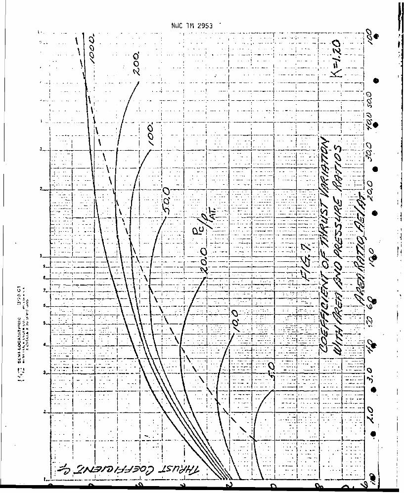
will not e xceed about 200 so that kwill be about 0.97. The theoretical coeffi-1 cient of thrust, CFT, can be calculated from:F,,TI I I I I I II

NWC TM 2953
where k is the specific heat ratio, PC' the chamber pressure, PE' the exit pres-sure, and P the atmospheric pressure. Though it can be calculated extremelyaccurately, the value is generally found on a graph where the values are plottedfor specific values of k, (AE/AT) area ratios, and pressure ratios. A typicalgraph is reproduced in Figure 7.
Therefore, all the values are known from the thrust equation and the pressure-
time history can be converted to a thrust-time history.
One other small refinement is generally applied and that is an estimation of&II I... . * r adi-=•...... ýeron rate. With graphite inserts in the throat, past
experience indicates that the radius increases at a rate of about 0.001 in/sec.
Once the thrust-time values are calculated and graphed, the area is plani-metered to determine the total impulse delivered by this specific motor design.The propellant weight was determined from planimetering the surface area-webburn-back graph so that the specific impulse can now be calculated for this pro-
pellant formulation in this motor design by:
XFdt . IT4 Jsp WTp
Though transient operating conditions have not been investigated, sufficientinformation should now be available to determine if this grain and nozzle designand the general propellant properties are capble of fulfilling the motor perform-ance requirements. If not, redesign efforts should be initiated.
PROPELLANTS
* Propellant formulations mainly contain an oxidizer and a fuel capable of
burning to completion once ignited. The properties can vary considerably depend-ing on the type and particle size of the oxidizer, the type of fuel, and the minor
13
NUC IM 2953- .. . . . . . . . : 9 - " ' " " • . . . . . . . . . .i • -. . r
. .. ._, " -. ., ... . i .t ..- :. - *,-,*-.. -. .o ... .....
* .. .'1. . . . : . .. .• . .. . .... : .. . . _ ... . .:. .. . ..r . . . .. .9 " ,. , ". . . . . .- ..- . .... - : I
9 ,:: " l . . . . , ... . . . . . -L-.- . . )
S..., •.,... i: :. i --i - I-: :: .? : -i :. ! . [.- :•i -
.. . .i , .. [ .- , - . ,.... . . ... ,,S.............. ... . . r .... 0 . . .. - - . .. ~... ... ,.. . , .
-. :' .. __._ . .- _ ... :...- ____ . - - --:-.i:- --.: * - • -'"::"
-- jI::.. :- ::,,-.- -• ... " ...- : :"- '1! ::--:•
8 -- . . .. ..... -. . . .....-- . . . .. - . . ... I- -'' -,__-,__-- '• -
•" ; . ..... T -__- .--- 9......... -... .. - " -. , -
- -- .- -- ", .. . .. "
. .... -: -.-. -.. - - , r ' - T
S. ... . .. .. . . :. I : . ... .- .-I ):- - - . - - -- - : . .: . . . ... .~--- . . . 9- - .--- -- I,---_.-.. ----....-.-.---.-. _•;# -•.... ......... ...... ,
" Ii; ..'" ... r." : j _ ! ' :T . ':3' : I .. '.,-:: "--:."I";
,.. ::::.-, :-: :- -i -._\. ' • I :I::: •- .. -.. -•- L :--i--: ,•" • : :S ; •• T -- '- .. .. rA-t-- ":/"V- -/-..-;m -Y--3-..', .. ' .--" .-7- .- Y-U -- ILt _-'-
4[. 4

NVIC TM 2953
ingredients used as ballistic modifiers. Often, propellant formulations can be
tailored to specific requirements -and motor applications-when necessary. Table 2
shows the extent to which the propellant properties will -vary:
TABLE 2. General Propellant Properties
_ - . Type Motors
Gas Generators Sustainers Boosters
rblO00 psi-70F 0.005 - 0.10 0.20 - 0.40 0.50 1.20
-n .3 -. 8 .3 - .8.8Isp 160 -180 180 - 210 210 -250C* 3000 - 4000 3500 - 4500 4000 - 5200
0 .057 - .059 .059 - .062 .062- .065- - .100- .400 .100 - .400 .100 - .450
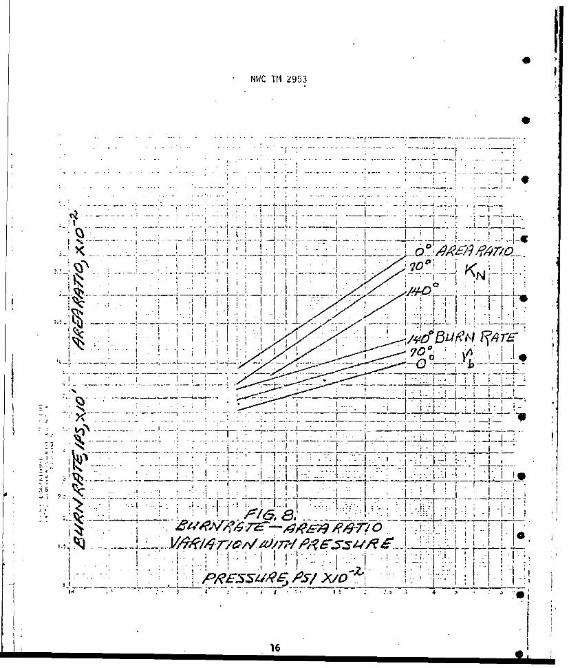
The pressure developed in a rocket motor depends on the burn rate of the pro-
*pellant which in turn depends upon the temperature of the grain and the pressure
-in. the combustor. Figure 8-shows the dependence of the burn rate and the KN
.area ratio on the pressure and temperature for a 'specific propellant formulation.....................................
Bis faImily of curves 6an-be-described by an exponential equation:
In r ='n In P + In C
.Here !n .C is'theY-iniercept and is controlled-by the temperature; an d n is theslope and is centrolled by the pressure: -It is important to select propellantfo'rmulations'with low pressure sensitivity constants that do not exceed aboutn 0.1,. The problein can be~explained from:-. . - -
" " ° ".......
:15
P . , , , , , ,
NVJC TM 2953
r sw .. AI ____
- ~7f:7Y I ~7>iIiK16
NWC TM 2953
As can be noted, as the n term increases approaching unity, the 1/1-n amplifi-
cation factor gro:vs rapidly. Now. for a propellant with n = 0.9 and a 10 percent
increase of surface, the pressure is amplified 159 percent to insure a motor
blow-up. If n = 0.8, and the burning area is increased by 10 percent, the pres-
sure is increased by 61 percent. The increased burning surface area can result
from a cracked propellant grain or possibly uninhibited areas that should have
been coated.
Two other important parameters obtained from the K and rb-PC curves are the
temperature sensitivity factors defined as:
rT - and
where ITTk
so that:
"P P ik(Te and r ro ecpPTT)
both theTTK and CT'p constants have units of % change per 'F and show how pressure
and burn rate vary with temperature, respectively.
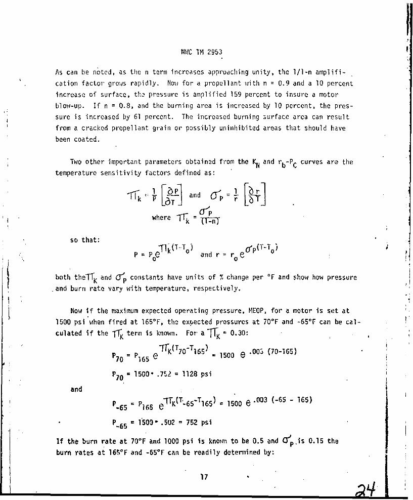
Now If the maximum expected operating pressure, MEOP, for a motor is set at
1500 psi when fired at 165°F, the expected pressures at 70°F and -65°F can be cal-
culated if the ITK term is known. For a K = 0.30:PTO P15 TeFI(T7-TI6)-"50rK~~ ~ T -T6005 (70-165)= 65 e 1500e
P70 1500" .7U2 = 1128 psi
andand5 P e'tK(T`T6T6 5-T16 5 ) 1500 e .003 (-65 - 165)P-65 = P65 e
P-6 5 = 1500- .5U2 - 752 psi
If the burn rate at 70°F and 1000 psi is knoin to be 0.5 and Cjpois 0.15 the
burn rates at 165OF and -65*F can be readily determined by:
17

NWC TM 2953
r 16 5 =r 70 0P(T165-T70) = o.5 e .0015 (165 - 70)
r 16 5 = 0.5-1.153 = 0.577 in/sec
and
r.5 5 rTO0 O7" s(T- 6 5 -T70 ) = 0.5 C.. 0 0 1 5 (-65 - 70)
r 65 = 0.5 -. 817 = 0.408 in/sec
These temperature sensitivity terms are very important to determine the effect
on motor performance. Low values are extremely desirable and values of zero
for bothl-T-K and T would be ideal and show that temperature has no effect on
the propellant performance.
Another important performance characteristic of the propellant formulation
is the characteristic exhaust velocity, designated as C*. This tern shows the
inherent energy content of the formulation independent of the nozzle design and
expansion characteristics. it is defined by this equation.
W Pdt
For most high energy propellants the characteristic exhaust velocity will vary
from about 4700 ft/sec to 5300 ft/sec. Lower energy gas generator propellants 0are generally cooler and have correspondingly lower values varying from about
3000 ftisec to 4000 ft/sec. The term is generlly m.easured -.by f"irin r'n1 test
motors and planimetering the pressure-time integral and knowing the throat area,
ATI and the propellant weight, WTp. . •
Once the nozzle design and operating characteristics are known so that a
thrust coefficient, CFT can be calculated, the characteristic exhaust velocity
can be converted to the specific impulse, Isp, by: •
I * F C*
Sp
This term has the units of lb-sec/lb and can also be determined from:
I 4dsp P
1851'5 L

NWC TM 2953
Example:
From the grain design sho;,n in Figure 5 and tabulated in Table 1 and the
prope'lant properties shown bWlow, convert this information to pressure-time
and thrust-time performance histories at 700 F. Assume the maximum chamber
pressure at 79VF is set at 1100 psi.
Propellant Properties:
C* 5060 ft/sec r = CP n
P = 0.063 lb/in3 r = 0.116 P.285
IT, 0.216 %/OF rl000 = 0.831 in/sec
Cj- =0.154 %/-F
First set the throat area so that the maximum surface will allow 1100 psi chamber
to be developed. Therefore,
SC C* 179d .063 1A T = 1•i-n 'I - 2853 lb'~£
g 32.2i11001.285
A 66339.4 13.782 in2AT 4 •&83.4
D= A = 4.189 in1.78 54
Now that the throat area is set, the pressures to be developed by the remaining
surfaces can be calculated and none can exceed the ilO0 psi. From
only the surface, S, will be varying so that:
[Qcc*] .063.116-5060 0.0833.o
1-T 1 -22a 1_7
and T-_ n 1.40
19
e-•to
NWC TM 2953 *
P1 = [1427 .0833]1.4 = [118.9]1.4 . 804 psi
P2 = [1476 1.0833]1.4 = [123.0]1"4 = 843 psi
P3 = [1524 .0833'1.4 = [127.0)1.4 = 882 psi
P4 [1559 0.0833]1"4 = [130.0)1.4 = 911 psi
P5 = [1579 0.0833]1'4 = [131.5 1.4 = 926 psi
P6 = [1654 * .0833)1.4 = [137.8]=.4 988 psi
P7 = [1722 -. 0833]1.4 = [143.431.4 = 1046 psiP8 = [1794' .0833]l"4 = [149.4]1.4 = 1100 psi
P9 = [234 4.0833]1"4 = [19.5)1'4 = 64 psi
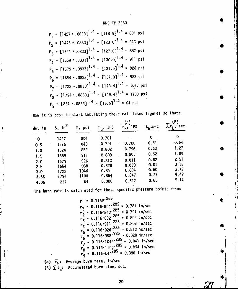
N.ow it is best to start tabulating these calculated figures so that:
i(A) (B)
dw, in S, in2 P, psi rbp US rb, IPS tbsec F-tb, sec
0 1427 804 0.781 - 0 0
0.5 1476 843 0.791 0.785 0.64 0.64
1.0 1524 882 0.802 0.796 0.63 1.27
1.5 1559 911 0.809 0.805 0.62 1.89
2.0 1579 926 0.813 0.811 0.62 2.51
2.5 1654 988 0.828 0.820 0.61 3.12
3.0 1722 1046 0.841 0.834 0.60 3.72
3.65 1794 1100 0.854 0.847 0.77 4.49
4.05 234 64 0.380 0.617 0.65 5.14
The burn rate is calcj•uated for these .•,p.cfir. pressure points from:
r - 0.116P'" 285
r, - 0.116,804"285 = 0.781. in/sec
r2 0.116,843.285 0.791 in/sec
r = 0.116.882"285 - 0.802 in/sec3 0.116.911. = 0.809 in/secr' 0.116-926.285 = 0.813 in/sec
r 0.116-988.285 = 0.828 in/sec
r 0.116,1046.285 = 0.841 in/sec7= 0.1161100"285 . 0.854 in/sec
r9 8 0.116,64.285 = 0.380 in/sec
(A) rb: Average burn rate, in/sec
(B) •tb: Accumulated burn time, sec.
20 i
NWC TM 2953
These burn rate data points are tabulated with the web burnback distances and
averaged so that by knowing the average burn rate and distance burned, burn
times can be calculated and accumulated burn times. Therefore, the pressure-
time performance can be graphed as shown in Figure 9.
The thrust-time history can now be calculated from the pressure-time data
points using the equation below:
r = Y CFT AT P C
At this time additional nozzle design data can be determined. From the average
pressure determined from Figure 9, the chamber to atmospheric pressure ratio can
be determined as about 68 (1000/14.7) and from Figure 7 the coefficient of thrust
and expansion ratio can be determined for optimum expansion. These values
are found to be: CFT = 1.60 and AE/AT = 9.0. Since the throat area was
found to be 13.782 in 2 earlier, the exit area should be 9.0-13.782 = 124.0 in 2
or a diameter of 12.6 in. Now if the nozzle is designed with an 180 half-angle,
the thrust can be estimated as:
F = 0. 94, 0 . 9 76 -1. 60 -13 . 7 82-PC
F = 20.23 Pc
and the data tabulated as:
dw, in Yt, sec p F, lbs
0 0 804 16265
0.5 0.64 843 17054
1.0 1.27 882 17843
1.5 1.89 911 184302.0 2.51 926 18734
2.5 3.12 988 199883.0 3.72 1046 21161
3.65 4.49 1100 22254
4.05 5.18 64 1295
These thrust-time data points can now be graphed as shown in Figure 10.
At this time all the important motor performance characteristics havebeen estimated for a 70'F motor test. These characteristics are sunrnarized
below:
21

NWC TM-1 2953 0
I22
I I
).7
V .* H
Vi
0
22•
I I I I f l

fIWC TM, 2953r
,a,
A k•
C I

NWC I'M 2953
Rocket Motor Performance Data*
Total impulse, lb-sec 95250
Integrated pressure, psi-sec 4615
Burn time, sec 4.37
Action time, sec 4.70
Maximum pressure, psi 1100
Average pressure, psi 1000
Maximum thrust, lb 22254
Average thrust, lb 21167
Specific impulse, lb-sec/lb 241.4
Propellant weight, lb 396.0
From the information supplied, it should be possible to calculate the
pressure-time and thrust-time performance histories at both +165°F and -65°F.
Once the motor performance has been estimated, surface area data refined,
and propellant characteristic data firm, the information can be programmed
for future performance information.
A summarization of many of' the motor perforqance equations is included
In Table 3 and Figure 11 shows various performance characteristics.
MOTOR COMPONENTS
From earlier discussions and the general motor drawing as shown in Figure l,. *it is obvious that a considerable number of inert components are necessary in
the rocket motor. These components must be able to withstand high temperature
and pressure loads and yet be lightweight and safe. Large safety factors can be
utilized in many fields of engineering to increase safety, but for flightweight
components the weight must be minimized. These inert components will account
for 15-20 percent of the total motor weight and should be minimized. Extremely
high performance motors will reduce the inert weight to about 5 percent. These
high propellant loading fraction motors generally produce the highest burn-
velocity missiles. A few of these components will be discussed:
24
r I I I I I I I i I I I i

NWC TM 2953
F
LJ
- 1j
~~~~-4 ...- m 1.T " •
_ ,
x - i; • ,. - I• •'•- -1 ,• •
I 25
1l INIC T.1 2953
7,g
el i
: u m -,,F y .l .t2 J
KqI
I
,---,
.cZ•?4'z6A/C ,
/•-•T, 1-II
NWC TM 2953,
Combustor:
The combustor is a thin-walled cylindrical pressure vessel with a head
closure at one end and a nozzle at the other. Case viall thickness must be
sufficient to withstand the maximum expected operating pressures when the case
is at the maximum expected temperature. The wall thickness car be estimated
from the yield stress of the metal selected for fabrication of a case of
radius R: - yt= y ield
Ymin
in this equation the Pyield is about 20 percent greater than the nominal value
calculated at the maximum operating temperature. *This value can be estimated
from:
P Fsp cc*71 1Lg'ATJ.]""
where the average plus one standard deviation value is used for C, ,-and C*.
The average less one standard deviation is used for AT. From typical experi-
ence this becomes: --""- ~ 1*
1. • 1.002-1I.05-1.005•1 .0',2
PMEOP ' .. 999 058412
" PMEOP 1 1.15 or 15% above nominal performance at the
maximum temperature due to variations of the-propellant properties and fabri-
cation of the nozzle. A set of arbitrary pressure design factors used for
booster motor design is summarized below: -
PROM = 1224 psi PNOM/PNOM = 1.00PMEOP 1400 P Eo/PNo!4 1.14
PHST 'ST1500 NOsT/ M = 1.22
.YIELD = 1680 .YIELD/PRON - 1.37
-__ PFAIL * 2100 .ýFAIL/PNoM 1.72
"C "" 27:i I II I
NWC T1 2953
The metal case material, Inconel 718, has a minimum yield of 150,000 psi and
a minimum ultimate of 190,000 psi. Therefore, for this case a wall thickness
estimate is:
P R 1680 7.5t -= T50000W 0MIN
tw = O.OB3 in.
Stress distributions in a combustor are extremely complex and this equation
can only be expected to produce approximate results. It does not consider
local loads at attachment points, bending loads, or thermal stresses. For
these reasons, reasonable safety factors must be utilized supplemented by
hydrostatic testing to demonstrate an acceptable design. While designing 4
for safety, excessive safety factors should not be used since weight must
be saved as the unit must fly.
Case Materials:
Since weight is a critical factor in moeor design, steel is mainly
used in construction due to thq high ultimate and yield strengths with
moderate densities. But, material selection is generally based on combustor
design and motor application.
Aluminum can often be used as a material of construction for small diameter
cases where the wall is not directly exposed to the propellant flames. Due to
the differences in strength, the wall thickness for an aluminum case is three
times that of a steel wall. Therefore, for a small motor case fabricated from
steel may be 0.020 in. thick and an aluminum case would be 0.060 in. Fabrica-
tion of case walls having thicknesses less than 0.050 in. will be extremely
difficult using ordinary techniques. Hence, comfibustors for large motors are
often fabricated from steel and small diameter motors utilize aluminum since
it's easier to maintain closer tolerances with thicker case walls. The main
disadvantage to using aluminum is that the strength rapidly decreases with 0
increasing temperature.
~28
NVIC TM 2953
Occasionally pressure vessels are fabricated from fiberglass filaments
bended with epoxy resins to produce a high strength material with a very low
density. Strength to density ratio may be as high as 1.3 x 10⁶ in; wihereas,
for steel it may only be about 0.6 x 106 in. Limitation of the fiberglass is
also the rapid loss of strength with increasing temperature.
For combustors that are required to operate for extended durations, high
strength high temperature materials will be required. This situation may beencountered for ramjets operating for about 180-240 seconds. Two materials
are often selected for this application: a nickel base alloy designated as
INCONEL, or a cobalt base material. Both materials, 1-718 nickel base and
L-605 cobalt base, were evaluated for potential application in an integral
rocket/ramjet application. Though both materials showed desirable high strengthhigh temperature properties, the 1-718 was selected due to the better machin-
ability characteristics.
Table 4 shows some candidate case materials and the physical properties.
TABLE 4. Case Materials and Physical Properties
Tensile Ultimate Density Tensile/DensityMatria h/in22 " b/in3 in
4130 Steel 180000 0.283 37
4140 Steel 220.000 0.283 778,000
7075-T6 Al 60,000 0.100 600,0002024-T4 Al 50,000 0.100 500,000
1-718 NI base 162,000 0.298 544,000
L-605 Co base 155,000 0.328 473,000
Fiberglass(filament/epoxy) 90,000 0.070 1.300,000
The extent to which the strength decreases as the temperature increases for
some of.these materials is shown in Figure 12.
29
HIWC ifl 2953t
1449
LI
I'Qj -Iri7_
1T T~TL rTH r-,T11 j7j I-
'7
I a
+1 T
7 f I
O\LT-, I-- --- ý I -H--
'171 . .7,
4-i-1
I~T I~~ I I1- -7
1*14-
................. ~I,''~~ i t--- ---- 7
30 ~5or
NIWC TM 2953,
Jo~ulation Materials: ... .. .. . ...
One of the more serious problems in rocket motor design is the high flame
temperatures developd in the combustor from burning high-energy propellants.
The problem of protecting metal parts from temperatures that exceed the melting
point of the material has received considerable attention in order to prevent
motor failure due to excessive heating of the combustor. This protective
material is designated as insulation and often completely coats the surface of
the component being protected. In Figure I it is shown as the material that
completely lines the internal surface of the combustor. An ideal heat--
resistant material, insulation, should be lightweight, occupy a minimum volume,
resist- chemical degradation, and resist thermal stresses.
Solutions to the high temperature problem are generally approached along
one of two paths: (1) ablation or (2) heat-sink. A brief description of each
t chn"••,que and some candid-ate materials tabulated below.
Ablative materials:
Materials for ablative cooling either sublime, decompose, or melt after
absorbing-a--certain amount of .heat. _1ass flow from-the ablative s ur-face.
reduces the amount of heat transferred to the motor wall. The heat of ablation
is .a.function of heat-flux measured in BTU/FT2-sec; each material has a minimum
heat-flux value below which ablation will notoccur. Above this value, the
higher the stagnation temperature, the greater.r>'ill be the rate of energy dis-
sipation. Many insulating materials are available. In general, it has been
determined that organic-fiber-reinforced plastics can withstand higher tempera-
tures for longer durations than asbestos or glass reinforced plastics. A rela-
tively rnew insulator is a silicone elastomer based compound, designated as
DC 93-104.. This material has been found effective in both-a rocket and a ramjet
--T-i•e-r-eTfmeiiet.- A -partial- I Is- ful-abtivematerial s-- is- summarized in
.- Table.5,. . . . -" ' ." " "-. . ... - - T .Z : . " - "
*1',.. .J-- :. , -_ -. .. . - -.. . -.. ...
Heat Sink Materials:
j Heat sink materials may take one or a combination of the following form.,:
31
NWC TM 2953
S
TABLE 5. Ablative Material Summary
Material Heat flux, Btu/sq ft/sec
Glass-phenolic fiberI 100
Nylon-phenolic fiber1 100
11Pure silica-phienolic fiberI 1,000
Graphite 2,000 (sublimes)QuartzI 2,000 (sublimes)
Teflon1 100
Silicone elastomers 2 7601
Oxy-acetylene flame torch.Oxy-kerosene flame torch.
1. Greater than normal thickness of structural components. ,
2. Lining layer of non-structural material with high heat capacity.
3. Liquid coolant circulating adjacent to the structural shell
internal surface.
The usefulness of heat-sink devices is confined to a narrow heat-flux
range of 0.1 to 10 BTU/Ft 2-sec. Table 6 is a partial lit of various heat-
sink materials in use.
An "In-Use" combustor is presently insulated with about O.80 ir. of zirmonia
applied by the plasma spray technique. Though a good insulator, the cLramic
material is quite brittle and easily damaged. Therefore, the DC 93-104 silicone
elastomer is being considered as a replacement. This material can be readily
spun in place and is quite pliable; unfortunately, about 0.375 in. is required
to insulate the combustor which reduces the propellant weight by about twenty 9
32
LH e'

NWC TM 2953
TABLE 6. Heat-Sink Materials Summary
Material Specific he0at' -TemperatureBtu/lb/°F range, OF
Metals
Beryllium 0.49 - 0.78 200 - 1,800
Magnesium 0.25 - 0.31 200 1,200
Aluminum 0.23 0.27 200 - 1,000
Chromium 0.12 - 0.18 200 - 2,000
Copper 0.09 - 0.12 200 - 1,800
Molybdenum 0.06 - 0.07 200 - 2,000
Ceramics
Beryllia 0.30 - 0.52 200 - 1,800
Magnesia 0.25 - 0.29 400 - i,800Aluminia 0.22 - 0.30 200 - 2,000
Quartz 0.18 - 0.29 200 - 2,000
Zirconia 0.12 - 0.14 200 - 1,6C0
Reinforced Plastics
Asbestos- I Iphenolic 0.31 - 0.36 100 - 500
Glass- I I
phenolic 0._3- 0,29 100 - 500
pounds. 1his represents abc .t 5 percent of the total propellant weight.
Asbestos-phenolic insulation was investigated but rejected since hand layup
would require considerable time and expense.
In general, there a-e no accepted equations that can be used tor selecting
the most desirable insulating material. The heat Oistrib'tion in a combustor
is quite complex and often an experts opinion is needed and this is followed
by extensive testing with well thermocoupled unit%. In addition, tiot only
thermal properties but physical properties and the ease of insulating the con,-
ponents must be considered.
33
NWC TM 2953
One technique to reduce the insulation problem is to design the motor with
a case bondd grain. This technique reduces the area of the combustor exposed
to the propellant flame to minimize the possibility of case burn-through.
Figure 1 shows this technique to keep the hot gases from the combustor wall.
Stress Release Bouts:
The propellant grain is -subjected to a number of stresses that must be
identified and compensated for. The principle stresses are due to pressure
gradients, flight acceleration, shrinkage during polymerization of the fuel-
binder, and differential expansion, during thermal cycling, between the case
and propellant bonded to it.
Propellant grains are cast at elevated temperatures and allowed to cool •
and polymerize. The resultant shrinkage develops residual stresses in the
propella. -harg'n arc not relieved by plastic deformation. These stresses
can result in ban' failure between propellant and liner or case to liner. If
liner or the bond is high streng~h, the propellant charge wrill probably fail
by cracking down the base of the star point. The result can be a catastropic
failure due to the increased burning surface area.
A technique to overcome this weakness is shown in Figure 1 and is called
the "stress release boot". The boot as shown is fabricated as two individual
items and bonded out at the maximuJn diameter area. Each piece is about
0.100 in. thick and made from a rubbery flexible material. Present booster
motors utilize nitrile-butadiene rubber filled with hydrated silica designated 0
as GEN GUARD V-45. In addition, boots fabricated from DC 93-104, a silicone
elastomer, have been successfully utilized.
The outside boot is bonded to the case or insulation and the inside boot
Is bonded to the propellant with the liner. When first cast, the split in the
release boot is closed, but, as tne propellant cools and polymerizes, the
split opens to release these grain stresses and minimize the possibility of
grain failure. The release boots also allow the rocket motor to be cycled
"over much greater temperature ranges than would otherwise be possible.
34
lI I

NWC TM 2953.
Though boots are'desirable, they should be minimized in size since they
reduce the volume inside the combustor allocated for propellant use. Often,
the relief boot can be a single layer with the insulation serving as the outer
boot. In addition, if the length-to-diameter is small enough, a boot at one
end may be sufficient to reduce grain stresses to an acceptable level.
Liner Materials:
Liner materials serve two specific functions: (1) insures a good interfacebond of propellant to boot and insulation and (2) inhibits burning so that
propellant burning only occurs on the unlined surfaces. In general, the liner
material is the bonding matrix or fuel material in the propellant. This
insures a good propellant to liner bond.
It is desirable that the propellant to liner bond be stronger than any
other bond. Therefore, if thermal or mechanical 5tresses are excessive, the
bond failitre will not occur between liner and propellant exposing new pro-
pellant snrfaces where burning can occur. When new uncontrolled areas become
exposed and burning is initiated, catastropic failures from motor blow-ups
usually occur.
The liner material is generally applied to the cylindrical section of
the combustor hy nouuring in a predetermined weight of material and spinning
on rollers for uniform distribution. On each ena, the boots are lined by
painting the material on to a predetermined thickness. The spun section thick-
ness can be as thin as 0.020 in. or as thick as 0.060 in.; these thicknesses
can be controlled within about 0.005 in. In general, thinner liners produce
greater bond strengths and increase the propellant loading fractions. There-
fore, the thin liners are much preferred and it is extremely desirable to
have both liner and propellant fuel from the same materials.
Motor Nozzle Design:
The nozzle is that part of a combustor which serves to direct and
accelerate the combustion gases to high velocities. A maximum thrust
coefficient consistent with minimum nozzle weight is the desired goal of
S35
NWC T14 2953,
the designer. A general view of a solid propellant motor is shown in
Figure 1 and the graph to estimate the theoretical coefficient of thrust is
included as Figure 7.
The nozzle throat area controls the chamber pressure; whereas, the pres-
sure ratio (PC/PA), area ratio (AE/AT), and the nozzle divergent half angle(N<} control the thrust amplification through the coefficient of thrust. Most
nozzles are of conical contour since they can be easily designed and readily
fabricated. Bell-shaped type nozzles have been developed as a technique to
improve the thrust coefficient while reducing weight but the complexity of the
curves for designing and fabricating reduce the desirability of this contour.
Most nozzles have half-angles (c<) around 100 to 200 to achieve the desired
expansion area ratio within a reasonable length. The convergent section can
have almost any symmetrical well-rounded shape with a radius approximately
equal to the throat diameter that faires into the expansion cone. The throat
area should have a short flat section about 5 percent of the throat diameter to
maintain the throat diameter during motor operation. Occasionally nozzles will
be partially or totally submerged within the combustor in order to achieve the
required expansion within a limited overall length. *1
Solid rocket nozzles are rarely cooled and, therefore, must retain shape
and strength at extremely high propellant combustion temperatures. Because
of the severe environment, very few materials function properly. Steel and
copper have been successfully employed in many applications; steel for a short
and copper for long burn times. In general copper is prohibitive due to the
excessive weight. Steel is acceptable for short durations; but as the burn
times are extended, thin coatings of zircnnia (ZrO2 ). or alumina (Al2 03 ) flame
sprayed on the surface increase erosion resistance with high performance pro-
pellants. Coatings should not exceed 0.00 'in. as excessively thick sections 0
will flake, spall, or crack due to variations in the coefficients of thermal
expansion.
The use of graphite as a small throat insert or Ls a full throat section
is extremely advantageous especially where the heat transfer is greatest.
36 •

NWC IM 2953 3,
Because of the high thermal conductivity and low thermal coefficient of expan-sion, graphite resists failure by thermal expansion. It has also been deter-mined that the tensile strength of graphite increases up to 5000'F. At thattemperature, and at 55,000 psi stress, the material displays an elongation of53 percent. Two materials used on booster motor programs and found acceptable
were H205 and ATJ graphite.
Figure 13 shows a booster motor nozzle which was designed for about 60 per-cent submergence within the combustor. After preliminary calculations werecompleted on this design, a detailed stress analysis was conducted using thefinite element stress technique for axisymmetric solids with orthotropictemperature dependent material properties. The computer program, designatedas SAAS II, is capable of predicting total stresses resulting from thermaland pressure loads. Results indicate marginal areas where design modificationsmay be necessary. Nozzle weight was found to be proportional to the totalimpulse and can bue estimated from:
WT 2.5 x 10⁴ dt
where jFdt, impulse, is given in lb-sec and WTN is in lbs. Though these
guidelines will help, nozzle design for solid propellant rocket motors is
"largely emperical.
INTERNAL BALLISTICS COMPUTER PROGRAM
The Internal Ballistics Computer Program (420004) is a proprietary programobtained from the Lockheed Propulsion Company. This program calculates the
pressure-time and thrust-time histories of a motor including accurate theoreti-cal calculations of both ignition and tail-off transients. The program tapenumber is 6369 and has been used on many local booster motor performance pre-dictions and has been found completely satisfactory.
Main assumptlons made to obtain this computer program were:
1. 'Combustion products are ideal gases.
Cl .37

-fWC Tf-I 2953
* -
38

NWC TM 2953en
2. Burning rate foliows Viejille's law, r CPn, from zero to
maximum pressure.
3. Effects of mass addition and erosive burning can be ignored.
4. The combustion chamber gases have negligible inertia.
5. Variation of C* with chamber pressure follows the relationship:
C*10 00 (P/P)100x
6. Propellant burn rate can be corrected for ambient temperature
(other than 70°F reference temperature) of the propellant by
the relation:
r =rREFe
where (
In order for the program to be used, thr motor must be designed and the
propellant properties knot-n. The information supplied to the computer falls
into two main categories:
. Su......... .a.... k an,,..n- t in as manv inrrements as desired.
II. Motor design and propellant properties:
1. Area, throat, in 2
2. Area, exit, in 2
3. Volume, motor, in 3
4. Temperature, ambient, OF
5. Pressure, ambient, psi
6. Pressure, blowout, psi
7. Lambda,8. Dischare, coefficient, C.
9. Gani•a,
39w
NWC TM 2953
10. Erosion, throat, in/sec ',11. Burn rate, in/sec
12. Exponent, pressure, n13. Temperature sensitivity,JTK, %/OF
14. Characteristic exhaust velocity, C*, ft/sec15. Density,p, lb/in3
16. Ignition time, sac
17. Burn reference pressure, psi
With this amount of information required aý input data, it is obvious 0
that the motor must be mainly designed and the propellant formulation selected.
"ihe program output is subdivided into three main tables of tabulated data as
summarized below:
Table I:
1. Time2. Pressure .01
3. Pressurization rate
4. Free volume5. Propellant weight consumed6. Propellant zonsumption rate
7. Insulation weight ablated
8. Insulation ablation rate
S. Current throat area values
Table II:
1. Time
2. Web burn-back
3. Propellant burning area
These values are greatly expanded by interpolating between
the values supplied from the input data. •
40
(1
NVWC TM 2953
Table III:
1. Time
2. Pressure
3. Thrust
4. Integrated pressure
5. Integrated thrust
6. Weight consumed
7. Current coefficient of thrust values
In addition to these three tables of inlormation, the program also handles
niozzle flow separation effects and denotes the times at which the flow is
separated by an "S." in the extreme right hand column. Concurrentiy wiLh the
tabulated data, pressure-time and thrust-time performance characteristics aregraphed for rapid visual inspection.
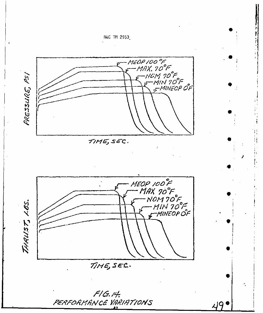
How the pressure and thrust performance varies with variations of ballistic
and fabrication components, in addition to temperature is included in Figure 14.
.
I I-
, • -~~~41 •,.j .
HVIC li 2953 P
04
MIN 70
A/FOP /0 -
,N0/4?O'oc

NWC TM 2953
BIBLIOGRAPHY
Vogel, J. M., Solid and Hbrici Rocket Technology, Volume I, Stanford University-
National Science Foundation, 1961.
Seifert, H. S.,. Spacc Technology, Based on Univers~ity of California Engineering
Course, 1959, John Wiley and Sons.
Sutton, G. P., Rocket Propulsion Elements, 1967, John Wiley and Sons.
Wimpress, R. N., Internal Ballistics of Solid-Fuel Rockets, 1950, McGraw-Hill
Book Co., Inc.
Barrere, M., Rocket Propulsion, Science Et Lettres, S.A., Liege, 1959.
Escallier, P., Internal Ballistics Computer Program (42004), description of
(NWC Reg. 4574-71-68), 1968.
Chemical Propulsion Information Agency. Solid Propellant Manual, CPIA/M2,
The Johns Hopkins University-Applied Physics Laboratory.
43