pdf 8/8: glossary rolling bearings - schaeffler group · pdf 8/8: glossary rolling bearings ......
TRANSCRIPT
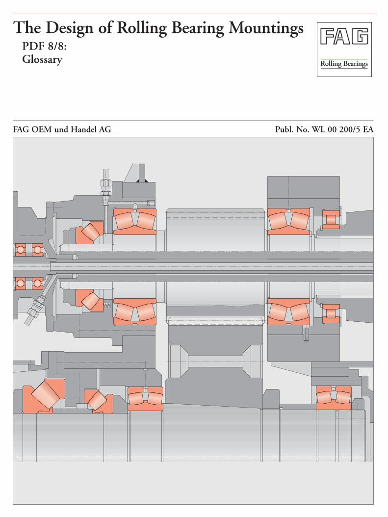
The Design of Rolling Bearing MountingsPDF 8/8:Glossary Rolling Bearings
FAG OEM und Handel AG Publ. No. WL 00 200/5 EA
The Design of Rolling Bearing Mountings
Design Examples covering Machines, Vehicles and Equipment
Publ. No. WL 00 200/5 EA
FAG OEM und Handel AGA company of the FAG Kugelfischer Group
Postfach 1260 · D-97419 SchweinfurtTelephone (0 97 21) 91-0 · Telefax (0 97 21) 91 34 35Telex 67345-0 fag d
Preface
This publication presents design examples coveringvarious machines, vehicles and equipment having onething in common: rolling bearings.
For this reason the brief texts concentrate on the roll-ing bearing aspects of the applications. The operationof the machine allows conclusions to be drawn aboutthe operating conditions which dictate the bearingtype and design, the size and arrangement, fits, lubri-cation and sealing.
Important rolling bearing engineering terms are print-ed in italics. At the end of this publication they aresummarized and explained in a glossary of terms, somesupplemented by illustrations.
Contents
Example Title PDF
GLOSSARY . . . . . . . . . . . . . . . . . . . . . . 8/8
Glossary
Additives
Additives are oil-soluble substances added to mineraloils or mineral oil products. By chemical or physicalaction, they change or improve lubricant properties(oxidation stability, EP properties, foaming, viscosity-temperature behaviour, setting point, flow properties,etc.). Additives are also an important factor in calculat-ing the attainable life (cp. also Factor K).
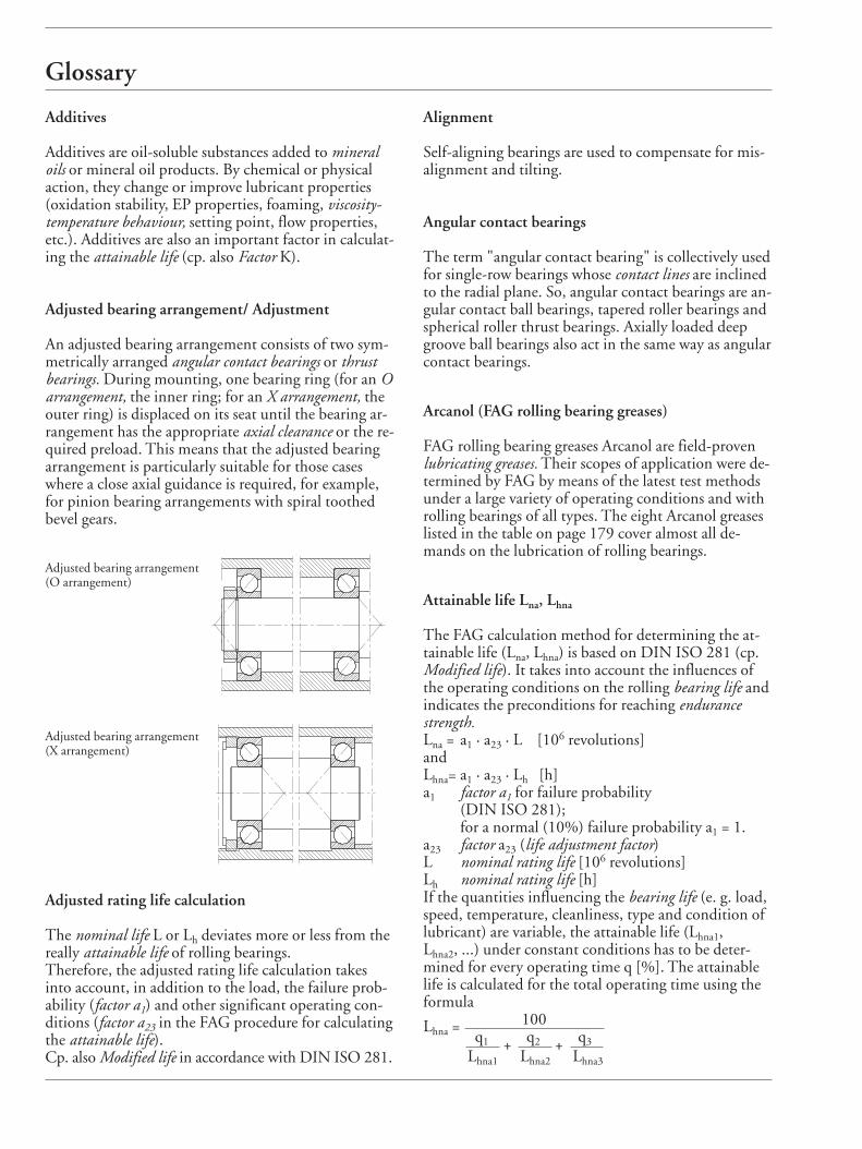
Adjusted bearing arrangement/ Adjustment
An adjusted bearing arrangement consists of two sym-metrically arranged angular contact bearings or thrustbearings. During mounting, one bearing ring (for an Oarrangement, the inner ring; for an X arrangement, theouter ring) is displaced on its seat until the bearing ar-rangement has the appropriate axial clearance or the re-quired preload. This means that the adjusted bearingarrangement is particularly suitable for those caseswhere a close axial guidance is required, for example,for pinion bearing arrangements with spiral toothedbevel gears.
Alignment
Self-aligning bearings are used to compensate for mis-alignment and tilting.
Angular contact bearings
The term "angular contact bearing" is collectively usedfor single-row bearings whose contact lines are inclinedto the radial plane. So, angular contact bearings are an-gular contact ball bearings, tapered roller bearings andspherical roller thrust bearings. Axially loaded deepgroove ball bearings also act in the same way as angularcontact bearings.
Arcanol (FAG rolling bearing greases)
FAG rolling bearing greases Arcanol are field-provenlubricating greases. Their scopes of application were de-termined by FAG by means of the latest test methodsunder a large variety of operating conditions and withrolling bearings of all types. The eight Arcanol greaseslisted in the table on page 179 cover almost all de-mands on the lubrication of rolling bearings.
Attainable life Lna, Lhna
The FAG calculation method for determining the at-tainable life (Lna, Lhna) is based on DIN ISO 281 (cp.Modified life). It takes into account the influences ofthe operating conditions on the rolling bearing life andindicates the preconditions for reaching endurancestrength.Lna = a1 · a23 · L [106 revolutions]andLhna= a1 · a23 · Lh [h]a1 factor a1 for failure probability
(DIN ISO 281); for a normal (10%) failure probability a1 = 1.
a23 factor a23 (life adjustment factor)L nominal rating life [106 revolutions] Lh nominal rating life [h]If the quantities influencing the bearing life (e. g. load,speed, temperature, cleanliness, type and condition oflubricant) are variable, the attainable life (Lhna1, Lhna2, ...) under constant conditions has to be deter-mined for every operating time q [%]. The attainablelife is calculated for the total operating time using theformula
Lhna = 100q1 + q2 + q3
Lhna1 Lhna2 Lhna3
Adjusted bearing arrangement (O arrangement)
Adjusted bearing arrangement (X arrangement)
Adjusted rating life calculation
The nominal life L or Lh deviates more or less from thereally attainable life of rolling bearings. Therefore, the adjusted rating life calculation takesinto account, in addition to the load, the failure prob-ability (factor a1) and other significant operating con-ditions (factor a23 in the FAG procedure for calculatingthe attainable life).Cp. also Modified life in accordance with DIN ISO 281.
Glossary
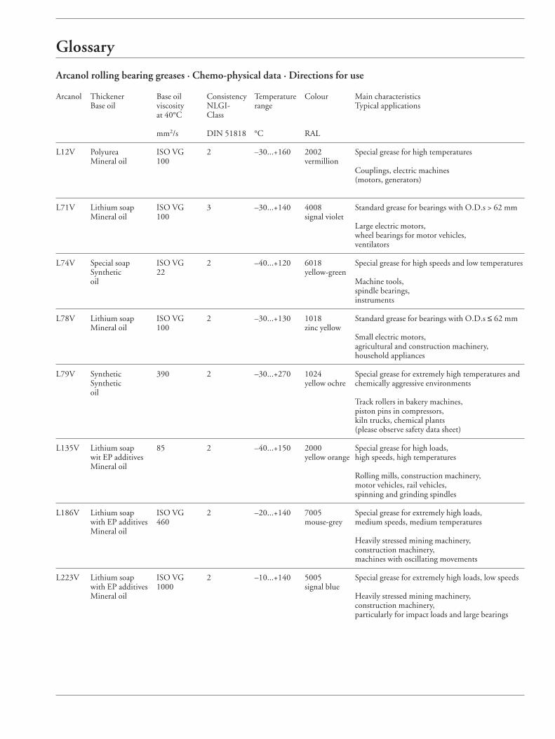
Arcanol rolling bearing greases · Chemo-physical data · Directions for use
Arcanol Thickener Base oil Consistency Temperature Colour Main characteristicsBase oil viscosity NLGI- range Typical applications
at 40°C Class
mm2/s DIN 51818 °C RAL
L12V Polyurea ISO VG 2 –30...+160 2002 Special grease for high temperaturesMineral oil 100 vermillion
Couplings, electric machines (motors, generators)
L71V Lithium soap ISO VG 3 –30...+140 4008 Standard grease for bearings with O.D.s > 62 mmMineral oil 100 signal violet
Large electric motors, wheel bearings for motor vehicles,ventilators
L74V Special soap ISO VG 2 –40...+120 6018 Special grease for high speeds and low temperaturesSynthetic 22 yellow-greenoil Machine tools,
spindle bearings, instruments
L78V Lithium soap ISO VG 2 –30...+130 1018 Standard grease for bearings with O.D.s ≤ 62 mmMineral oil 100 zinc yellow
Small electric motors, agricultural and construction machinery, household appliances
L79V Synthetic 390 2 –30...+270 1024 Special grease for extremely high temperatures and Synthetic yellow ochre chemically aggressive environmentsoil
Track rollers in bakery machines,piston pins in compressors, kiln trucks, chemical plants (please observe safety data sheet)
L135V Lithium soap 85 2 –40...+150 2000 Special grease for high loads, wit EP additives yellow orange high speeds, high temperatures Mineral oil
Rolling mills, construction machinery,motor vehicles, rail vehicles,spinning and grinding spindles
L186V Lithium soap ISO VG 2 –20...+140 7005 Special grease for extremely high loads, with EP additives 460 mouse-grey medium speeds, medium temperaturesMineral oil
Heavily stressed mining machinery, construction machinery, machines with oscillating movements
L223V Lithium soap ISO VG 2 –10...+140 5005 Special grease for extremely high loads, low speeds with EP additives 1000 signal blueMineral oil Heavily stressed mining machinery,
construction machinery,particularly for impact loads and large bearings
Glossary
Axial clearance
The axial clearance of a bearing is the total possible ax-ial displacement of one bearing ring measured withoutload. There is a difference between the axial clearanceof the unmounted bearing and the axial operating clear-ance existing when the bearing is mounted and run-ning at operating temperature.
Base oil
is the oil contained in a lubricating grease. The amountof oil varies with the type of thickener and the greaseapplication. The penetration number and the frictionalbehaviour of the grease vary with the amount of baseoil and its viscosity.
Basic a23II value
The basic a23II value is the basis for determining factora23, used in attainable life calculation.
Bearing life
The life of dynamically stressed rolling bearings, as de-fined by DIN ISO 281, is the operating time until fail-ure due to material fatigue (fatigue life). By means of the classical calculation method, a com-parison calculation, the nominal rating life L or Lh, isdetermined; by means of the refined FAG calculationprocess, the attainable life Lna or Lhna is determined (seealso factor a23).
Cage
The cage of a rolling bearing prevents the rolling ele-ments from rubbing against each other. It keeps themevenly spaced and guides them through unloaded sec-tions of the bearing circumference.The cage of a needle roller bearing also has to guidethe needle rollers parallel to the axis. In the case of sep-arable bearings the cage retains the rolling element set,thus facilitating bearing mounting. Rolling bearingcages are classified into the categories pressed cages andmachined/moulded cages.
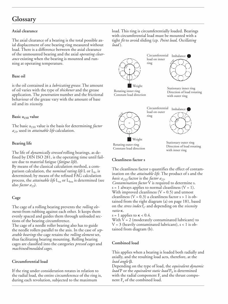
Circumferential load
If the ring under consideration rotates in relation tothe radial load, the entire circumference of the ring is,during each revolution, subjected to the maximum
load. This ring is circumferentially loaded. Bearingswith circumferential load must be mounted with atight fit to avoid sliding (cp. Point load, Oscillating load ).
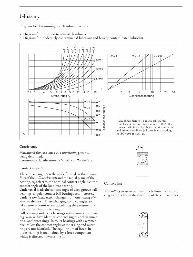
Cleanliness factor s
The cleanliness factor s quantifies the effect of contam-ination on the attainable life. The product of s and thebasic a23II factor is the factor a23.Contamination factor V is required to determine s. s = 1 always applies to normal cleanliness (V = 1).With improved cleanliness (V = 0.5) and utmostcleanliness (V = 0.3) a cleanliness factor s > 1 is ob-tained from the right diagram (a) on page 181, basedon the stress index fs* and depending on the viscosity ratio k. s = 1 applies to k < 0.4.With V = 2 (moderately contaminated lubricant) to V = 3 (heavily contaminated lubricant), s < 1 is ob-tained from diagram (b).
Combined load
This applies when a bearing is loaded both radially andaxially, and the resulting load acts, therefore, at theload angle b.Depending on the type of load, the equivalent dynamicload P or the equivalent static load P0 is determinedwith the radial component Fr and the thrust compo-nent Fa of the combined load.
Circumferentialload on innerring
Circumferentialload on outerring
Weight
Imbalance
Imbalance
Weight
Rotating inner ringConstant load direction
Rotating outer ringConstant load direction
Stationary inner ringDirection of load rotatingwith outer ring
Stationary outer ringDirection of load rotatingwith inner ring
Glossary
Consistency
Measure of the resistance of a lubricating grease to being deformed.Consistency classification to NLGI, cp. Penetration.
Contact angle a
The contact angle a is the angle formed by the contactlines of the rolling elements and the radial plane of thebearing. a0 refers to the nominal contact angle, i.e. thecontact angle of the load-free bearing. Under axial loads the contact angle of deep groove ballbearings, angular contact ball bearings etc. increases.Under a combined load it changes from one rolling ele-ment to the next. These changing contact angles aretaken into account when calculating the pressure dis-tribution within the bearing. Ball bearings and roller bearings with symmetrical roll-ing elements have identical contact angles at their innerrings and outer rings. In roller bearings with asymmet-rical rollers the contact angles at inner ring and outerring are not identical. The equilibrium of forces inthese bearings is maintained by a force componentwhich is directed towards the lip.
α
Contact line
The rolling elements transmit loads from one bearingring to the other in the direction of the contact lines.
Diagram for determining the cleanliness factor s
a Diagram for improved to utmost cleanlinessb Diagram for moderately contaminated lubricant and heavily contaminated lubricant
1
V = 1
2.5 3 4 5 6 7 8 9 10 12 14 16 20 2 3 5 10 15 20 30
κ=1
κ=0.7
κ=0.5
1
V = 0.5 V = 0.3
κ=0.6
κ=0.
9κ=
0.8
κ=1.
5
κ=2
κ=2.
5κ=
3
κ=3.
5
κ=4
0.1
0.2
0.3
0.70.5
V = 1
V = 2
V = 3
0.05
0.03
a
b
Cleanliness factor sStress index fs*
Cle
anlin
ess
fact
or s
A cleanliness factor s > 1 is attainable for full-complement bearings only if wear in roller/rollercontact is eliminated by a high-viscosity lubricantand utmost cleanliness (oil cleanliness accordingto ISO 4406 at least 11/7).
Glossary
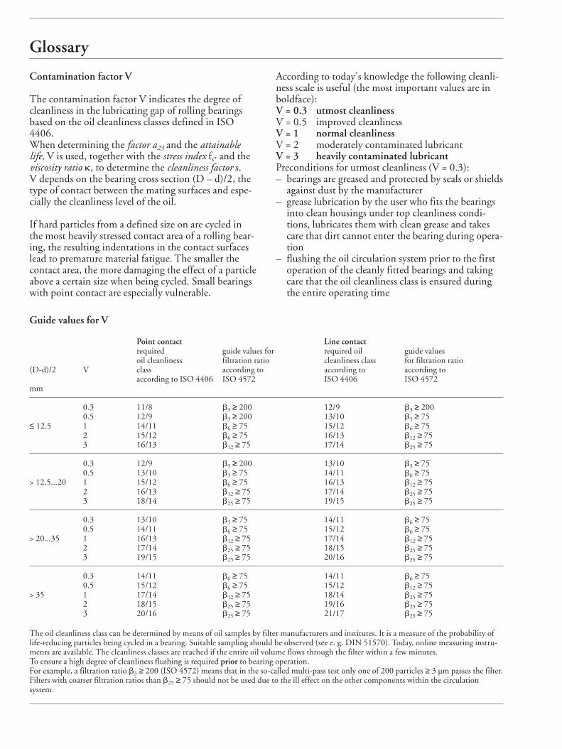
Contamination factor V
The contamination factor V indicates the degree ofcleanliness in the lubricating gap of rolling bearingsbased on the oil cleanliness classes defined in ISO4406. When determining the factor a23 and the attainablelife, V is used, together with the stress index fs* and theviscosity ratio k, to determine the cleanliness factor s.V depends on the bearing cross section (D – d)/2, thetype of contact between the mating surfaces and espe-cially the cleanliness level of the oil.
If hard particles from a defined size on are cycled inthe most heavily stressed contact area of a rolling bear-ing, the resulting indentations in the contact surfaceslead to premature material fatigue. The smaller thecontact area, the more damaging the effect of a particleabove a certain size when being cycled. Small bearingswith point contact are especially vulnerable.
According to today's knowledge the following cleanli-ness scale is useful (the most important values are inboldface):V = 0.3 utmost cleanliness V = 0.5 improved cleanliness V = 1 normal cleanlinessV = 2 moderately contaminated lubricantV = 3 heavily contaminated lubricantPreconditions for utmost cleanliness (V = 0.3):– bearings are greased and protected by seals or shields
against dust by the manufacturer– grease lubrication by the user who fits the bearings
into clean housings under top cleanliness condi-tions, lubricates them with clean grease and takescare that dirt cannot enter the bearing during opera-tion
– flushing the oil circulation system prior to the firstoperation of the cleanly fitted bearings and takingcare that the oil cleanliness class is ensured duringthe entire operating time
Guide values for V
Point contact Line contactrequired guide values for required oil guide valuesoil cleanliness filtration ratio cleanliness class for filtration ratio
(D-d)/2 V class according to according to according toaccording to ISO 4406 ISO 4572 ISO 4406 ISO 4572
mm
0.3 11/8 b3 ≥ 200 12/9 b3 ≥ 2000.5 12/9 b3 ≥ 200 13/10 b3 ≥ 75
≤ 12.5 1 14/11 b6 ≥ 75 15/12 b6 ≥ 752 15/12 b6 ≥ 75 16/13 b12 ≥ 753 16/13 b12 ≥ 75 17/14 b25 ≥ 75
0.3 12/9 b3 ≥ 200 13/10 b3 ≥ 750.5 13/10 b3 ≥ 75 14/11 b6 ≥ 75
> 12.5...20 1 15/12 b6 ≥ 75 16/13 b12 ≥ 752 16/13 b12 ≥ 75 17/14 b25 ≥ 753 18/14 b25 ≥ 75 19/15 b25 ≥ 75
0.3 13/10 b3 ≥ 75 14/11 b6 ≥ 750.5 14/11 b6 ≥ 75 15/12 b6 ≥ 75
> 20...35 1 16/13 b12 ≥ 75 17/14 b12 ≥ 752 17/14 b25 ≥ 75 18/15 b25 ≥ 753 19/15 b25 ≥ 75 20/16 b25 ≥ 75
0.3 14/11 b6 ≥ 75 14/11 b6 ≥ 750.5 15/12 b6 ≥ 75 15/12 b12 ≥ 75
> 35 1 17/14 b12 ≥ 75 18/14 b25 ≥ 752 18/15 b25 ≥ 75 19/16 b25 ≥ 753 20/16 b25 ≥ 75 21/17 b25 ≥ 75
The oil cleanliness class can be determined by means of oil samples by filter manufacturers and institutes. It is a measure of the probability oflife-reducing particles being cycled in a bearing. Suitable sampling should be observed (see e. g. DIN 51570). Today, online measuring instru-ments are available. The cleanliness classes are reached if the entire oil volume flows through the filter within a few minutes. To ensure a high degree of cleanliness flushing is required prior to bearing operation.For example, a filtration ratio b3 ≥ 200 (ISO 4572) means that in the so-called multi-pass test only one of 200 particles ≥ 3 µm passes the filter.Filters with coarser filtration ratios than b25 ≥ 75 should not be used due to the ill effect on the other components within the circulationsystem.
Glossary
Preconditions for normal cleanliness (V = 1):– good sealing adapted to the environment– cleanliness during mounting– oil cleanliness according to V = 1– observing the recommended oil change intervals
Possible causes of heavy lubricant contamination (V = 3):– the cast housing was inadequatly cleaned– abraded particles from components which are sub-
ject to wear enter the circulating oil system of themachine
– foreign matter penetrates into the bearing due tounsatisfactory sealing
– water which entered the bearing, also condensationwater, caused standstill corrosion or deterioration ofthe lubricant properties
The necessary oil cleanliness class according to ISO4406 is an objectively measurable level of the contami-nation of a lubricant.
In accordance with the particle-counting mehod, thenumber of all particles > 5 µm and all particles > 15 µmare allocated to a certain ISO oil cleanliness classs.For example, an oil cleanliness class 15/12 accordingto ISO 4406 means that between 16,000 and 32,000particles > 5 µm and between 2,000 and 4,000 parti-cles > 15 µm are present per 100 ml of a fluid.
A defined filtration ratio bx should exist in order toreach the oil cleanliness required.
The filtration ratio is the ratio of all particles > x µmbefore passing the filter to the particles > x µm whichhave passed the filter. For example, a filtration ratio b3 ≥ 200 means that in the so-called multi-pass test(ISO 4572) only one of 200 particles ≥ 3 µm passesthe filter.
Counter guidance
Angular contact bearings and single-direction thrustbearings accommodate axial forces only in one direc-tion. A second, symmetrically arranged bearing mustbe used for "counter guidance", i.e. to accommodatethe axial forces in the other direction.
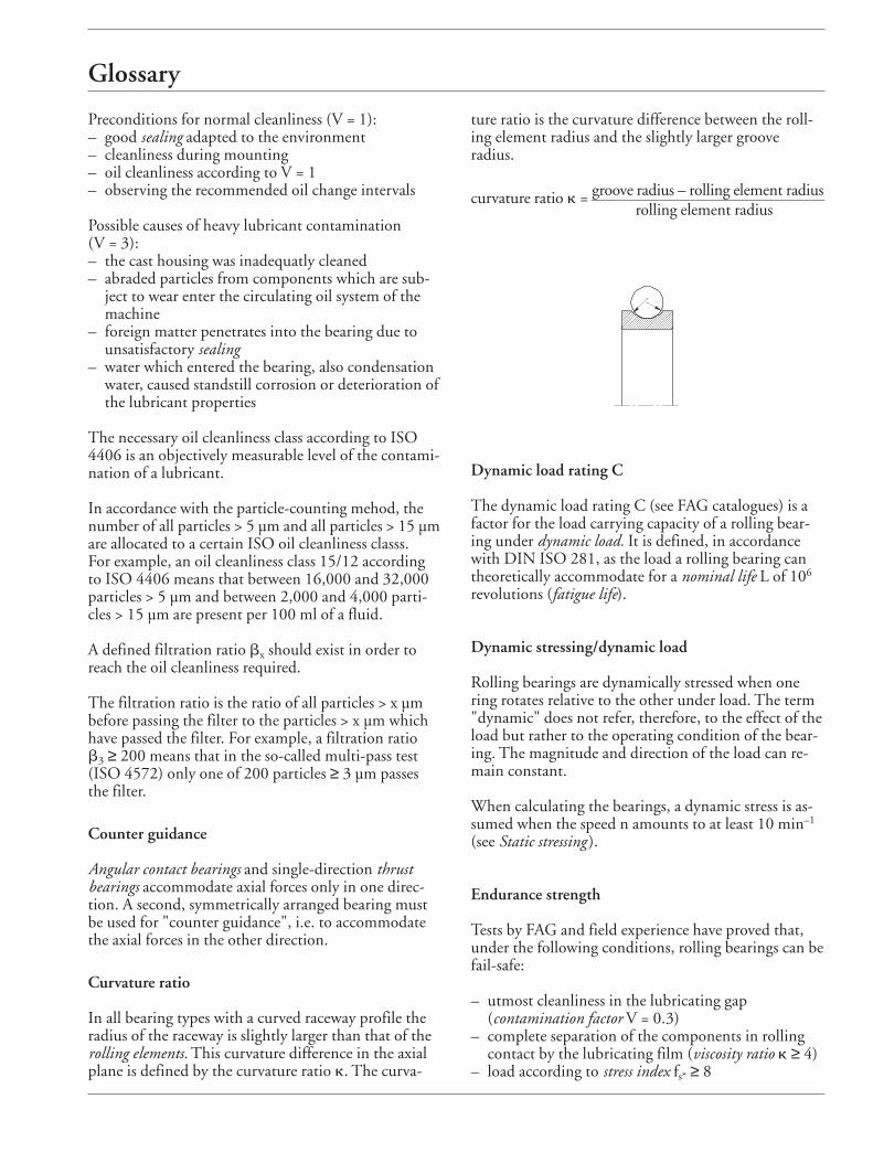
Curvature ratio
In all bearing types with a curved raceway profile theradius of the raceway is slightly larger than that of therolling elements. This curvature difference in the axialplane is defined by the curvature ratio k. The curva-
ture ratio is the curvature difference between the roll-ing element radius and the slightly larger groove radius.
curvature ratio k = groove radius – rolling element radiusrolling element radius
Dynamic load rating C
The dynamic load rating C (see FAG catalogues) is afactor for the load carrying capacity of a rolling bear-ing under dynamic load. It is defined, in accordancewith DIN ISO 281, as the load a rolling bearing cantheoretically accommodate for a nominal life L of 106
revolutions (fatigue life).
Dynamic stressing/dynamic load
Rolling bearings are dynamically stressed when onering rotates relative to the other under load. The term"dynamic" does not refer, therefore, to the effect of theload but rather to the operating condition of the bear-ing. The magnitude and direction of the load can re-main constant.
When calculating the bearings, a dynamic stress is as-sumed when the speed n amounts to at least 10 min–1
(see Static stressing ).
Endurance strength
Tests by FAG and field experience have proved that,under the following conditions, rolling bearings can befail-safe:
– utmost cleanliness in the lubricating gap (contamination factor V = 0.3)
– complete separation of the components in rolling contact by the lubricating film (viscosity ratio k ≥ 4)
– load according to stress index fs* ≥ 8
Glossary
EP additives
Wear-reducing additives in lubricating greases and lubri-cating oils, also referred to as extreme pressure lubri-cants.
Equivalent dynamic load P
For dynamically loaded rolling bearings operatingunder a combined load, the calculation is based on theequivalent dynamic load. This is a radial load for radialbearings and an axial and centrical load for axial bear-ings, having the same effect on fatigue as the combinedload. The equivalent dynamic load P is calculated bymeans of the following equation:
P = X · Fr + Y · Fa [kN]
Fr radial load [kN]Fa axial load [kN]X radial factor (see FAG catalogues)Y thrust factor (see FAG catalogues)
Equivalent static load P0
Statically stressed rolling bearings which operate undera combined load are calculated with the equivalent stat-ic load. It is a radial load for radial bearings and an axial and centric load for thrust bearings, having thesame effect with regard to permanent deformation asthe combined load.The equivalent static load P0 is calculated with the formula:
P = X0 · Fr + Y0 · Fa [kN]
Fr radial load [kN]Fa axial load [kN]X0 radial factor (see FAG catalogues)Y0 thrust factor (see FAG catalogues)
Factor a1
Generally (nominal rating life L10), 10 % failure prob-ability is taken. The factor a1 is also used for failureprobabilities between 10 % and 1 % for the calcula-tion of the attainable life, see following table.
Failure probability % 10 5 4 3 2 1
Fatiguelife L10 L5 L4 L3 L2 L1Factor a1 1 0.62 0.53 0.44 0.33 0.21
Factor a23 (life adjustment factor)
The a23 factor is used to calculate the attainable life.FAG use a23 instead of the mutually dependent adjust-ment factors for material (a2) and operating conditions(a3) indicated in DIN ISO 281.
a23 = a2 · a3
The a23 factor takes into account effects of:
– amount of load (stress index fs*), – lubricating film thickness (viscosity ratio k), – lubricant additives (value K), – contaminants in the lubricating gap (cleanliness
factor s),– bearing type (value K).
The diagram on page 185 is the basis for the determi-nation of the a23 factor using the basic a23II value. Thea23 factor is obtained from the equation a23II · s (s be-ing the cleanliness factor).
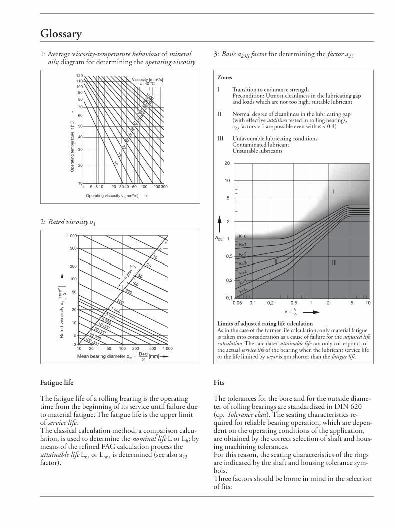
The viscosity ratio k = n/n1 and the value K are requiredfor locating the basic value. The most important zone(II) in the diagram applies to normal cleanliness (s = 1).
The viscosity ratio k is a measure of the lubricating filmdevelopment in the bearing.
n operating viscosity of the lubricant, depending on thenominal viscosity (at 40 °C) and the operating tem-perature t (fig. 1). In the case of lubricating greases,n is the operating viscosity of the base oil.
n1 rated viscosity, depending on mean bearing diameterdm and operating speed n (fig. 2).
The diagram (fig. 3) for determining the basic a23IIfactor is subdivided into zones I, II and III.
Most applications in rolling bearing engineering arecovered by zone II. It applies to normal cleanliness(contamination factor V = 1). In zone II, a23 can be de-termined as a function of k by means of value K.
With K = 0 to 6, a23II is found on one of the curves inzone II of the diagram.
With K > 6, a23 must be expected to be in zone III. Insuch a case conditions should be improved so thatzone II can be reached.
Glossary
1: Average viscosity-temperature behaviour of mineral oils; diagram for determining the operating viscosity
3: Basic a23II factor for determining the factor a23
1500100068046032022015010068
4632
2215
10
12011010090
80
70
60
50
40
30
20
104 6 8 10 20 30 40 60 100 200 300
Viscosity [mm2/s]at 40 °C
Op
erat
ing
tem
per
atur
e t
[°C
]
Operating viscosity ν [mm2/s]
Mean bearing diameter dm = D+d2
[mm]
n [m
in-1 ]
100 000
50 000
20 000
10 000
5 000
2 000
1 000
500
200
100
50
20
10
5
21 000
500
200
100
50
20
10
5
310 20 50 100 200 500 1 000
Rat
ed v
isco
sity
ν1
mm
2
s
2: Rated viscosity n1
Fatigue life
The fatigue life of a rolling bearing is the operatingtime from the beginning of its service until failure dueto material fatigue. The fatigue life is the upper limitof service life.The classical calculation method, a comparison calcu-lation, is used to determine the nominal life L or Lh; bymeans of the refined FAG calculation process the attainable life Lna or Lhna is determined (see also a23factor).
κ = ν1
ν
a23II
20
10
5
2
1
0,5
0,2
0,10,05 0,1 0,2 0,5 1 2 5 10
K=0
K=1
K=2
K=3
K=4
K=5
K=6
I
II III
Zones
I Transition to endurance strengthPrecondition: Utmost cleanliness in the lubricating gap and loads which are not too high, suitable lubricant
II Normal degree of cleanliness in the lubricating gap (with effective additives tested in rolling bearings, a23 factors > 1 are possible even with k < 0.4)
III Unfavourable lubricating conditionsContaminated lubricantUnsuitable lubricants
Limits of adjusted rating life calculationAs in the case of the former life calculation, only material fatigueis taken into consideration as a cause of failure for the adjusted lifecalculation. The calculated attainable life can only correspond tothe actual service life of the bearing when the lubricant service lifeor the life limited by wear is not shorter than the fatigue life.
Fits
The tolerances for the bore and for the outside diame-ter of rolling bearings are standardized in DIN 620(cp. Tolerance class). The seating characteristics re-quired for reliable bearing operation, which are depen-dent on the operating conditions of the application,are obtained by the correct selection of shaft and hous-ing machining tolerances.For this reason, the seating characteristics of the ringsare indicated by the shaft and housing tolerance sym-bols. Three factors should be borne in mind in the selectionof fits:
Glossary
1. Safe retention and uniform support of the bearingrings
2. Simplicity of mounting and dismounting3. Axial freedom of the floating bearingThe simplest and safest means of ring retention in thecircumferential direction is achieved by a tight fit. A tight fit will support the rings evenly, a factor whichis indispensable for the full utilization of the load car-rying capacity. Bearing rings accommodating a circum-ferential load or an oscillating load are always fittedtightly. Bearing rings accommodating a point load maybe fitted loosely.The higher the load the tighter should be the interfer-ence fit provided, particularly for shock loading. Thetemperature gradient between bearing ring and matingcomponent should also be taken into account. Bearingtype and size also play a role in the selection of the cor-rect fit.
Floating bearing
In a locating/floating bearing arrangement the floatingbearing compensates for axial thermal expansion.Cylindrical roller bearings of NU and N designs, aswell as needle roller bearings, are ideal floating bear-ings. Differences in length are compensated for in thefloating bearing itself. The bearing rings can be giventight fits.Non-separable bearings, such as deep groove ball bear-ings and spherical roller bearings, can also be used asfloating bearings. In such a case one of the two bearingrings is given a loose fit, with no axial mating surfaceso that it can shift freely on its seat.
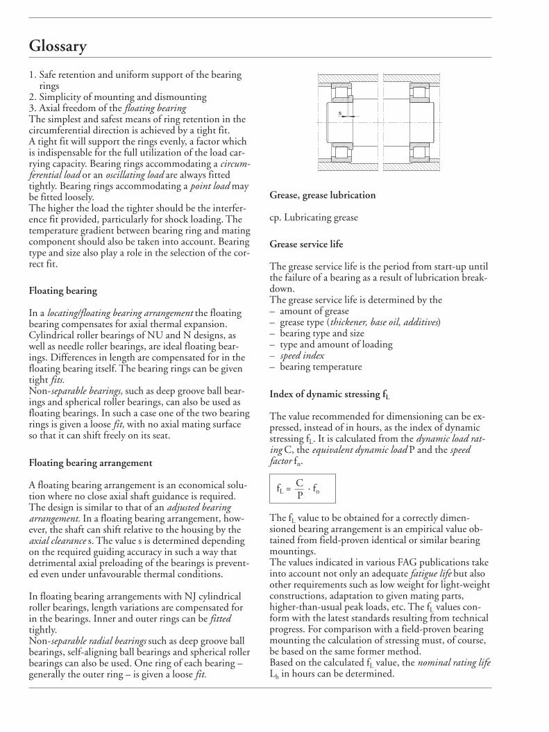
Floating bearing arrangement
A floating bearing arrangement is an economical solu-tion where no close axial shaft guidance is required.The design is similar to that of an adjusted bearing arrangement. In a floating bearing arrangement, how-ever, the shaft can shift relative to the housing by theaxial clearance s. The value s is determined dependingon the required guiding accuracy in such a way thatdetrimental axial preloading of the bearings is prevent-ed even under unfavourable thermal conditions.
In floating bearing arrangements with NJ cylindricalroller bearings, length variations are compensated forin the bearings. Inner and outer rings can be fittedtightly. Non-separable radial bearings such as deep groove ballbearings, self-aligning ball bearings and spherical rollerbearings can also be used. One ring of each bearing –generally the outer ring – is given a loose fit.
Grease, grease lubrication
cp. Lubricating grease
Grease service life
The grease service life is the period from start-up untilthe failure of a bearing as a result of lubrication break-down.The grease service life is determined by the – amount of grease – grease type (thickener, base oil, additives) – bearing type and size – type and amount of loading – speed index– bearing temperature
Index of dynamic stressing fL
The value recommended for dimensioning can be ex-pressed, instead of in hours, as the index of dynamicstressing fL. It is calculated from the dynamic load rat-ing C, the equivalent dynamic load P and the speed factor fn.
fL = C · fnP
The fL value to be obtained for a correctly dimen-sioned bearing arrangement is an empirical value ob-tained from field-proven identical or similar bearingmountings.The values indicated in various FAG publications takeinto account not only an adequate fatigue life but alsoother requirements such as low weight for light-weightconstructions, adaptation to given mating parts, higher-than-usual peak loads, etc. The fL values con-form with the latest standards resulting from technicalprogress. For comparison with a field-proven bearingmounting the calculation of stressing must, of course,be based on the same former method.Based on the calculated fL value, the nominal rating lifeLh in hours can be determined.
s
Glossary
Lh = 500 · fLp [h]
p = 3 for ball bearings
p = 10 for roller bearings and needle roller bearings3
Index of static stressing fs
The index of static stressing fs for statically loaded bear-ings is calculated to ensure that a bearing with an ade-quate load carrying capacity has been selected. It is cal-culated from the static load rating C0 and the equiva-lent static load P0.
fs = C0P0
The index fs is a safety factor against permanent defor-mations of the contact areas between raceway and themost heavily loaded rolling element. A high fs value isrequired for bearings which must run smoothly andparticularly quietly. Smaller values suffice where amoderate degree of running quietness is required. Thefollowing values are generally recommended:
fs = 1.5...2.5 for a high degreefs = 1...1.5 for a normal degreefs = 0.7...1 for a moderate degree
K value
The K value is an auxiliary quantity needed to deter-mine the basic a23II factor when calculating the attain-able life of a bearing.
K = K1 + K2
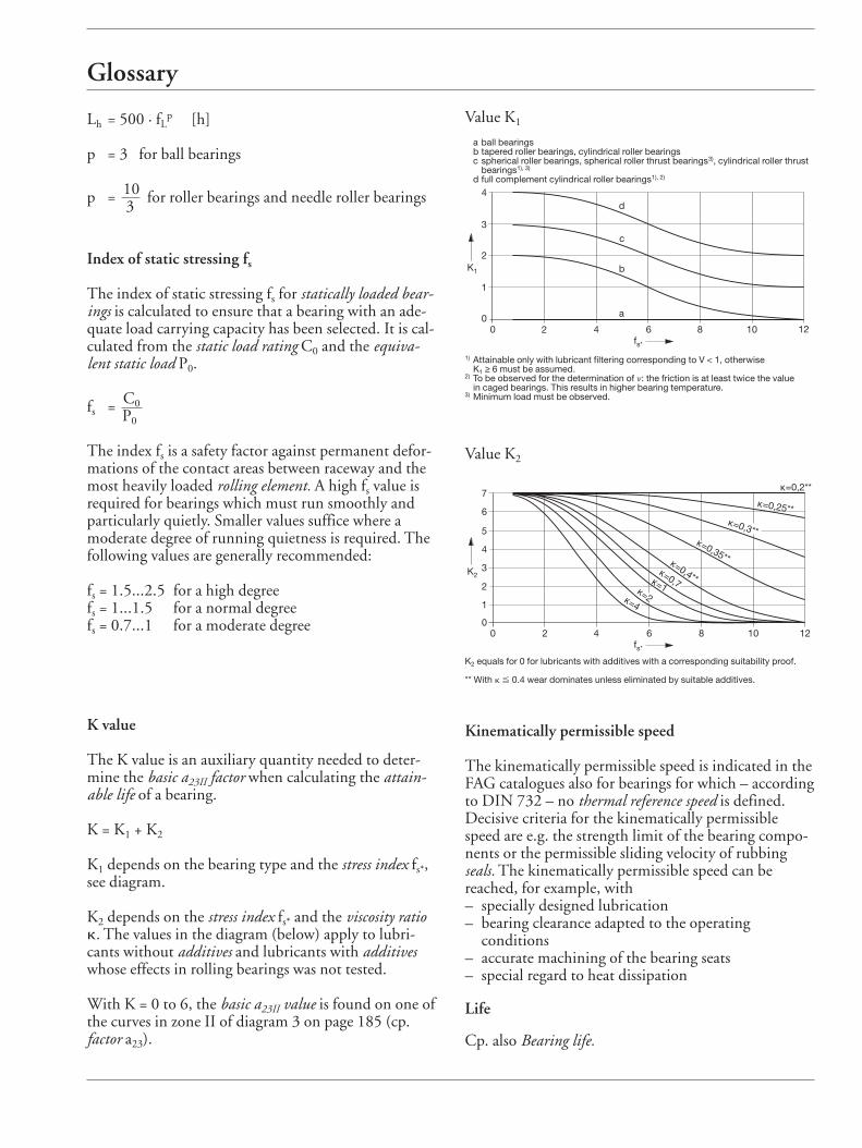
K1 depends on the bearing type and the stress index fs*,see diagram.
K2 depends on the stress index fs* and the viscosity ratiok. The values in the diagram (below) apply to lubri-cants without additives and lubricants with additiveswhose effects in rolling bearings was not tested.
With K = 0 to 6, the basic a23II value is found on one ofthe curves in zone II of diagram 3 on page 185 (cp.factor a23).
Value K1
4
3
2
1
00 2 4 6 8 10 12
a
K1
fs*
b
c
d
a ball bearingsb tapered roller bearings, cylindrical roller bearingsc spherical roller bearings, spherical roller thrust bearings3), cylindrical roller thrust
bearings1), 3)
d full complement cylindrical roller bearings1), 2)
1) Attainable only with lubricant filtering corresponding to V < 1, otherwise K1 ≥ 6 must be assumed.
2) To be observed for the determination of n: the friction is at least twice the value in caged bearings. This results in higher bearing temperature.
3) Minimum load must be observed.
Value K2
7
6
5
4
3
2
1
00 2 4 6 8 10 12
fs*
K2
κ=0,25**κ=0,3**
κ=0,35**κ=0,4**κ=0,7κ=1κ=2κ=4
κ=0,2**
K2 equals for 0 for lubricants with additives with a corresponding suitability proof.
** With k % 0.4 wear dominates unless eliminated by suitable additives.
Kinematically permissible speed
The kinematically permissible speed is indicated in theFAG catalogues also for bearings for which – accordingto DIN 732 – no thermal reference speed is defined. Decisive criteria for the kinematically permissiblespeed are e.g. the strength limit of the bearing compo-nents or the permissible sliding velocity of rubbingseals. The kinematically permissible speed can bereached, for example, with – specially designed lubrication– bearing clearance adapted to the operating
conditions– accurate machining of the bearing seats– special regard to heat dissipation
Life
Cp. also Bearing life.
Glossary
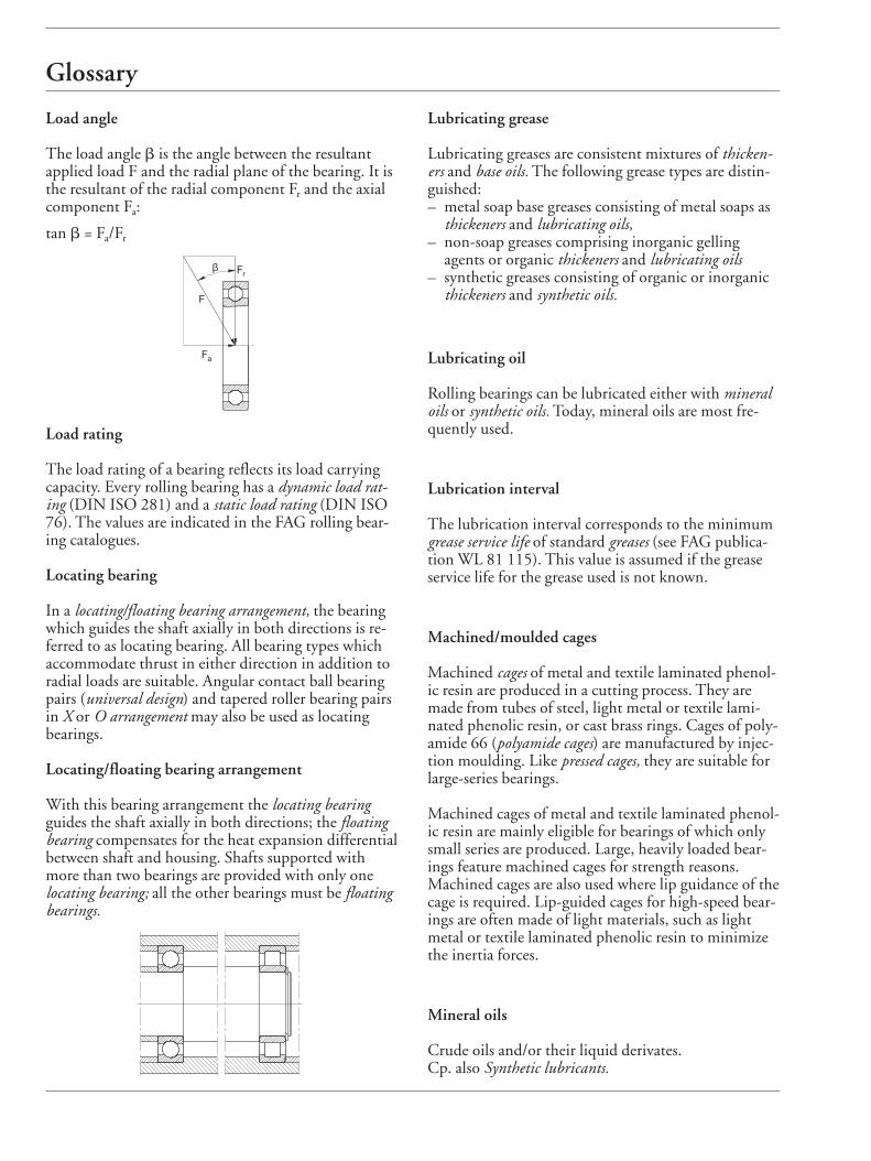
Load angle
The load angle b is the angle between the resultant applied load F and the radial plane of the bearing. It isthe resultant of the radial component Fr and the axialcomponent Fa:
tan b = Fa/Fr
Lubricating grease
Lubricating greases are consistent mixtures of thicken-ers and base oils. The following grease types are distin-guished:– metal soap base greases consisting of metal soaps as
thickeners and lubricating oils,– non-soap greases comprising inorganic gelling
agents or organic thickeners and lubricating oils– synthetic greases consisting of organic or inorganic
thickeners and synthetic oils.
Lubricating oil
Rolling bearings can be lubricated either with mineraloils or synthetic oils. Today, mineral oils are most fre-quently used.
Lubrication interval
The lubrication interval corresponds to the minimumgrease service life of standard greases (see FAG publica-tion WL 81 115). This value is assumed if the greaseservice life for the grease used is not known.
Machined/moulded cages
Machined cages of metal and textile laminated phenol-ic resin are produced in a cutting process. They aremade from tubes of steel, light metal or textile lami-nated phenolic resin, or cast brass rings. Cages of poly-amide 66 (polyamide cages) are manufactured by injec-tion moulding. Like pressed cages, they are suitable forlarge-series bearings.
Machined cages of metal and textile laminated phenol-ic resin are mainly eligible for bearings of which onlysmall series are produced. Large, heavily loaded bear-ings feature machined cages for strength reasons. Machined cages are also used where lip guidance of thecage is required. Lip-guided cages for high-speed bear-ings are often made of light materials, such as lightmetal or textile laminated phenolic resin to minimizethe inertia forces.
Mineral oils
Crude oils and/or their liquid derivates.Cp. also Synthetic lubricants.
β
F
Fr
Fa
Load rating
The load rating of a bearing reflects its load carryingcapacity. Every rolling bearing has a dynamic load rat-ing (DIN ISO 281) and a static load rating (DIN ISO76). The values are indicated in the FAG rolling bear-ing catalogues.
Locating bearing
In a locating/floating bearing arrangement, the bearingwhich guides the shaft axially in both directions is re-ferred to as locating bearing. All bearing types whichaccommodate thrust in either direction in addition toradial loads are suitable. Angular contact ball bearingpairs (universal design) and tapered roller bearing pairsin X or O arrangement may also be used as locatingbearings.
Locating/floating bearing arrangement
With this bearing arrangement the locating bearingguides the shaft axially in both directions; the floatingbearing compensates for the heat expansion differentialbetween shaft and housing. Shafts supported withmore than two bearings are provided with only one locating bearing; all the other bearings must be floatingbearings.
Glossary
Modified life
The standard Norm DIN ISO 281 introduced, in ad-dition to the nominal rating life L10, the modified lifeLna to take into account, apart from the load, the influence of the failure probability (factor a1), of thematerial (factor a2) and of the operating conditions(factor a3). DIN ISO 281 indicates no figures for the factor a23(a23 = a2 · a3). With the FAG calculation process for theattainable life (Lna, Lhna), however, operating condi-tions can be expressed in terms of figures by the factora23.
NLGI class
Cp. Penetration.
Nominal rating life
The standardized calculation method for dynamicallystressed rolling bearings is based on material fatigue (for-mation of pitting) as the cause of failure. The life for-mula is:
L10 = L = ( C )p[106 revolutions]
P
L10 is the nominal rating life in millions of revolutionswhich is reached or exceeded by at least 90 % of a largegroup of identical bearings.In the formula,C dynamic load rating [kN]P equivalent dynamic load [kN]p life exponentp = 3 for ball bearingsp = 10/3 for roller bearings and needle roller bearings.
Where the bearing speed is constant, the life can be ex-pressed in hours.
Lh10 = Lh = L · 106[h]
n · 60
n speed [min–1]Lh can also be determined by means of the index of dy-namic stressing fL. The nominal rating life L or Lh applies to bearingsmade of conventional rolling bearing steel and the usu-al operating conditions (good lubrication, no extremetemperatures, normal cleanliness).The nominal rating life deviates more or less from thereally attainable life of rolling bearings. Influences suchas lubricating film thickness, cleanliness in the lubri-cating gap, lubricant additives and bearing type aretaken into account in the adjusted rating life calculationby the factor a23.
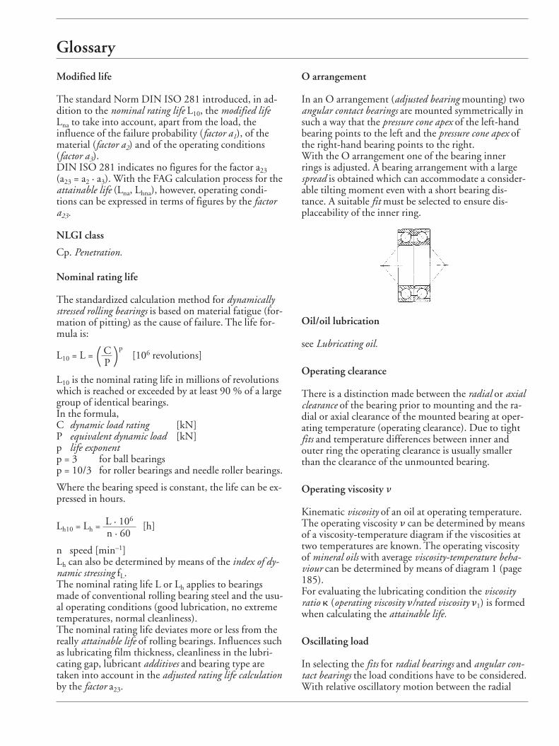
O arrangement
In an O arrangement (adjusted bearing mounting) twoangular contact bearings are mounted symmetrically insuch a way that the pressure cone apex of the left-handbearing points to the left and the pressure cone apex ofthe right-hand bearing points to the right.With the O arrangement one of the bearing innerrings is adjusted. A bearing arrangement with a largespread is obtained which can accommodate a consider-able tilting moment even with a short bearing dis-tance. A suitable fit must be selected to ensure dis-placeability of the inner ring.
Oil/oil lubrication
see Lubricating oil.
Operating clearance
There is a distinction made between the radial or axialclearance of the bearing prior to mounting and the ra-dial or axial clearance of the mounted bearing at oper-ating temperature (operating clearance). Due to tightfits and temperature differences between inner andouter ring the operating clearance is usually smallerthan the clearance of the unmounted bearing.
Operating viscosity n
Kinematic viscosity of an oil at operating temperature.The operating viscosity n can be determined by meansof a viscosity-temperature diagram if the viscosities attwo temperatures are known. The operating viscosityof mineral oils with average viscosity-temperature beha-viour can be determined by means of diagram 1 (page185).For evaluating the lubricating condition the viscosityratio k (operating viscosity n/rated viscosity n1) is formedwhen calculating the attainable life.
Oscillating load
In selecting the fits for radial bearings and angular con-tact bearings the load conditions have to be considered.With relative oscillatory motion between the radial
Glossary
load and the ring to be fitted, conditions of "oscillat-ing load" occur. Both bearing rings must be given atight fit to avoid sliding (cp. circumferential load ).
Penetration
Penetration is a measure of the consistency of a lubricat-ing grease. Worked penetration is the penetration of agrease sample that has been worked, under exactly de-fined conditions, at 25 °C. Then the depth of penetra-tion – in tenths of a millimetre – of a standard coneinto a grease-filled vessel is measured.
Penetration of common rolling bearing greases
NLGI class Worked penetration(Penetration classes) 0.1 mm
1 310...3402 265...2953 220...2504 175...205
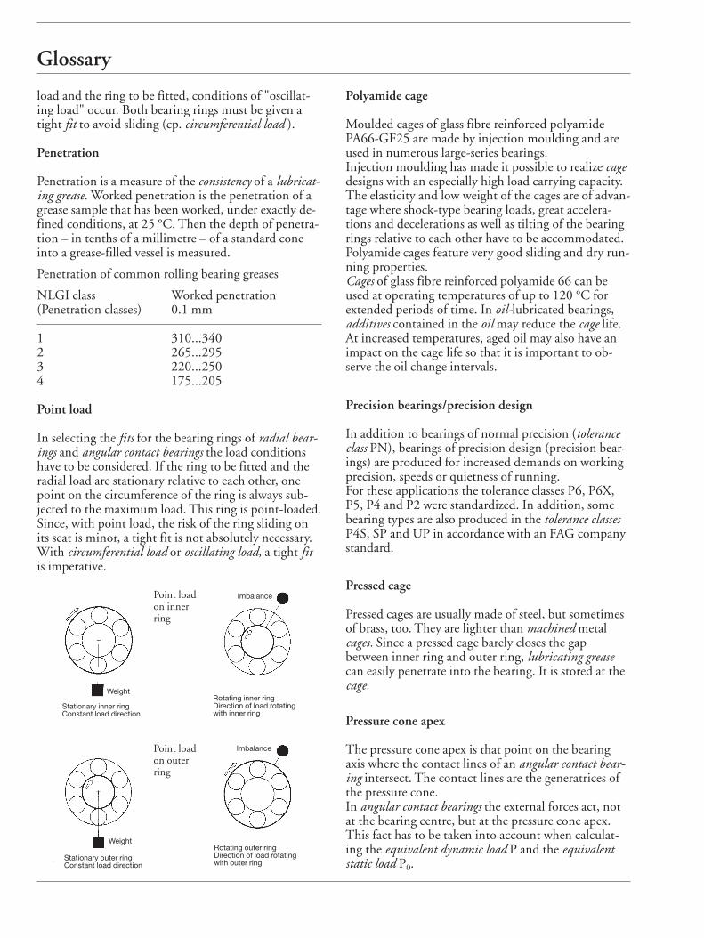
Point load
In selecting the fits for the bearing rings of radial bear-ings and angular contact bearings the load conditionshave to be considered. If the ring to be fitted and theradial load are stationary relative to each other, onepoint on the circumference of the ring is always sub-jected to the maximum load. This ring is point-loaded.Since, with point load, the risk of the ring sliding onits seat is minor, a tight fit is not absolutely necessary.With circumferential load or oscillating load, a tight fitis imperative.
Polyamide cage
Moulded cages of glass fibre reinforced polyamidePA66-GF25 are made by injection moulding and areused in numerous large-series bearings. Injection moulding has made it possible to realize cagedesigns with an especially high load carrying capacity.The elasticity and low weight of the cages are of advan-tage where shock-type bearing loads, great accelera-tions and decelerations as well as tilting of the bearingrings relative to each other have to be accommodated.Polyamide cages feature very good sliding and dry run-ning properties.Cages of glass fibre reinforced polyamide 66 can beused at operating temperatures of up to 120 °C for extended periods of time. In oil-lubricated bearings,additives contained in the oil may reduce the cage life.At increased temperatures, aged oil may also have animpact on the cage life so that it is important to ob-serve the oil change intervals.
Precision bearings/precision design
In addition to bearings of normal precision (toleranceclass PN), bearings of precision design (precision bear-ings) are produced for increased demands on workingprecision, speeds or quietness of running. For these applications the tolerance classes P6, P6X,P5, P4 and P2 were standardized. In addition, somebearing types are also produced in the tolerance classesP4S, SP and UP in accordance with an FAG companystandard.
Pressed cage
Pressed cages are usually made of steel, but sometimesof brass, too. They are lighter than machined metal cages. Since a pressed cage barely closes the gapbetween inner ring and outer ring, lubricating greasecan easily penetrate into the bearing. It is stored at thecage.
Pressure cone apex
The pressure cone apex is that point on the bearingaxis where the contact lines of an angular contact bear-ing intersect. The contact lines are the generatrices ofthe pressure cone.In angular contact bearings the external forces act, notat the bearing centre, but at the pressure cone apex.This fact has to be taken into account when calculat-ing the equivalent dynamic load P and the equivalentstatic load P0.
Point loadon innerring
Point loadon outerring
Weight
Imbalance
Imbalance
Weight
Stationary inner ringConstant load direction
Stationary outer ringConstant load direction
Rotating inner ringDirection of load rotatingwith inner ring
Rotating outer ringDirection of load rotatingwith outer ring
Glossary
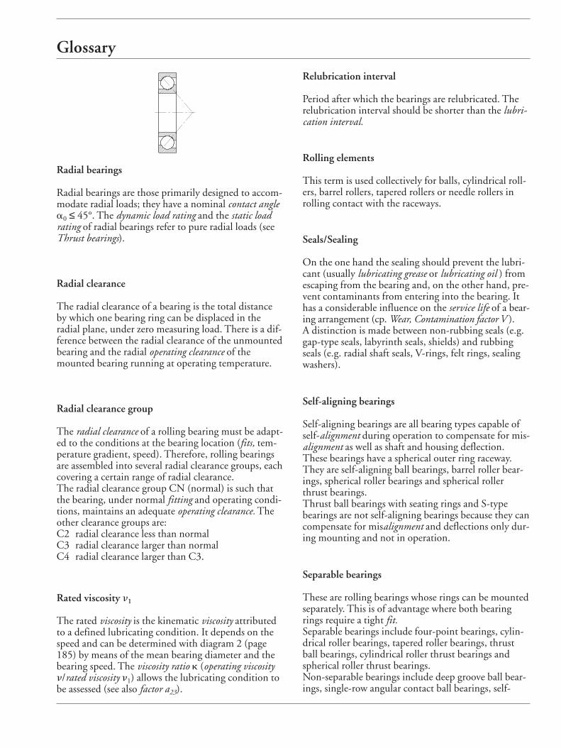
Radial bearings
Radial bearings are those primarily designed to accom-modate radial loads; they have a nominal contact anglea0 ≤ 45°. The dynamic load rating and the static loadrating of radial bearings refer to pure radial loads (seeThrust bearings).
Radial clearance
The radial clearance of a bearing is the total distanceby which one bearing ring can be displaced in the radial plane, under zero measuring load. There is a dif-ference between the radial clearance of the unmountedbearing and the radial operating clearance of themounted bearing running at operating temperature.
Radial clearance group
The radial clearance of a rolling bearing must be adapt-ed to the conditions at the bearing location (fits, tem-perature gradient, speed). Therefore, rolling bearingsare assembled into several radial clearance groups, eachcovering a certain range of radial clearance.The radial clearance group CN (normal) is such thatthe bearing, under normal fitting and operating condi-tions, maintains an adequate operating clearance. Theother clearance groups are:C2 radial clearance less than normalC3 radial clearance larger than normalC4 radial clearance larger than C3.
Rated viscosity n1
The rated viscosity is the kinematic viscosity attributedto a defined lubricating condition. It depends on thespeed and can be determined with diagram 2 (page185) by means of the mean bearing diameter and thebearing speed. The viscosity ratio k (operating viscosityn/rated viscosity n1) allows the lubricating condition tobe assessed (see also factor a23).
Relubrication interval
Period after which the bearings are relubricated. Therelubrication interval should be shorter than the lubri-cation interval.
Rolling elements
This term is used collectively for balls, cylindrical roll-ers, barrel rollers, tapered rollers or needle rollers inrolling contact with the raceways.
Seals/Sealing
On the one hand the sealing should prevent the lubri-cant (usually lubricating grease or lubricating oil ) fromescaping from the bearing and, on the other hand, pre-vent contaminants from entering into the bearing. Ithas a considerable influence on the service life of a bear-ing arrangement (cp. Wear, Contamination factor V ).A distinction is made between non-rubbing seals (e.g.gap-type seals, labyrinth seals, shields) and rubbingseals (e.g. radial shaft seals, V-rings, felt rings, sealingwashers).
Self-aligning bearings
Self-aligning bearings are all bearing types capable ofself-alignment during operation to compensate for mis-alignment as well as shaft and housing deflection.These bearings have a spherical outer ring raceway.They are self-aligning ball bearings, barrel roller bear-ings, spherical roller bearings and spherical rollerthrust bearings.Thrust ball bearings with seating rings and S-typebearings are not self-aligning bearings because they cancompensate for misalignment and deflections only dur-ing mounting and not in operation.
Separable bearings
These are rolling bearings whose rings can be mountedseparately. This is of advantage where both bearingrings require a tight fit. Separable bearings include four-point bearings, cylin-drical roller bearings, tapered roller bearings, thrustball bearings, cylindrical roller thrust bearings andspherical roller thrust bearings. Non-separable bearings include deep groove ball bear-ings, single-row angular contact ball bearings, self-
Glossary
aligning ball bearings, barrel roller bearings and spheri-cal roller bearings.
Service life
This is the life during which the bearing operates reli-ably.The fatigue life of a bearing is the upper limit of its ser-vice life. Often this limit is not reached due to wear orlubrication breakdown (cpl. Grease service life).
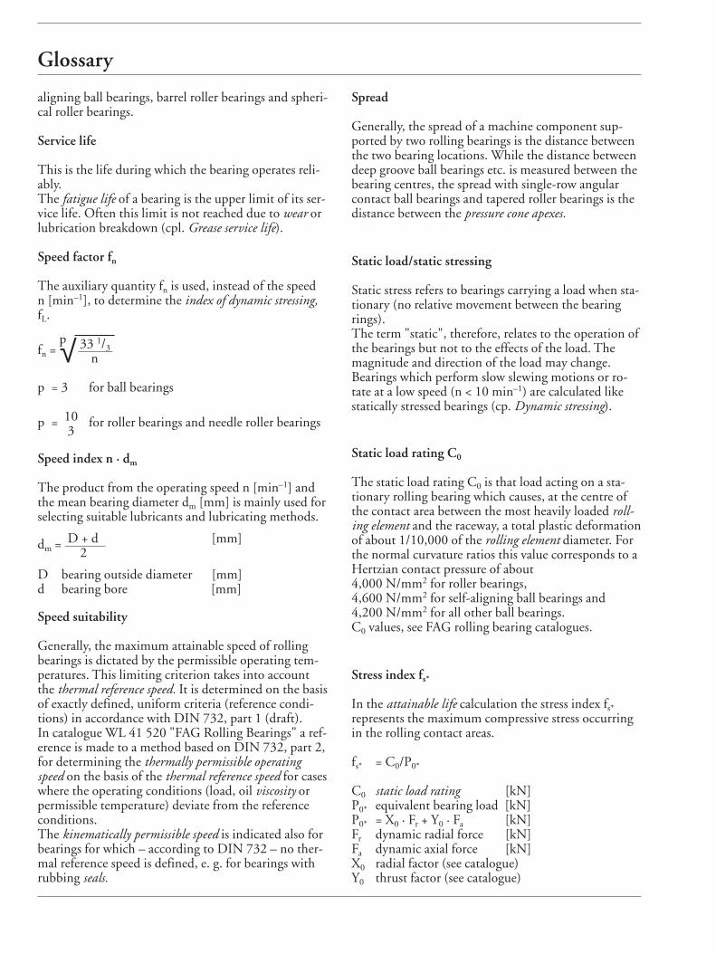
Speed factor fn
The auxiliary quantity fn is used, instead of the speed n [min–1], to determine the index of dynamic stressing,fL.
fn =p√ 33 1/3
n
p = 3 for ball bearings
p = 10 for roller bearings and needle roller bearings3
Speed index n · dm
The product from the operating speed n [min–1] andthe mean bearing diameter dm [mm] is mainly used forselecting suitable lubricants and lubricating methods.
dm = D + d [mm]2
D bearing outside diameter [mm]d bearing bore [mm]
Speed suitability
Generally, the maximum attainable speed of rollingbearings is dictated by the permissible operating tem-peratures. This limiting criterion takes into accountthe thermal reference speed. It is determined on the basisof exactly defined, uniform criteria (reference condi-tions) in accordance with DIN 732, part 1 (draft). In catalogue WL 41 520 "FAG Rolling Bearings" a ref-erence is made to a method based on DIN 732, part 2,for determining the thermally permissible operatingspeed on the basis of the thermal reference speed for caseswhere the operating conditions (load, oil viscosity orpermissible temperature) deviate from the referenceconditions. The kinematically permissible speed is indicated also forbearings for which – according to DIN 732 – no ther-mal reference speed is defined, e. g. for bearings withrubbing seals.
Spread
Generally, the spread of a machine component sup-ported by two rolling bearings is the distance betweenthe two bearing locations. While the distance betweendeep groove ball bearings etc. is measured between thebearing centres, the spread with single-row angularcontact ball bearings and tapered roller bearings is thedistance between the pressure cone apexes.
Static load/static stressing
Static stress refers to bearings carrying a load when sta-tionary (no relative movement between the bearingrings).The term "static", therefore, relates to the operation ofthe bearings but not to the effects of the load. Themagnitude and direction of the load may change. Bearings which perform slow slewing motions or ro-tate at a low speed (n < 10 min–1) are calculated likestatically stressed bearings (cp. Dynamic stressing).
Static load rating C0
The static load rating C0 is that load acting on a sta-tionary rolling bearing which causes, at the centre ofthe contact area between the most heavily loaded roll-ing element and the raceway, a total plastic deformationof about 1/10,000 of the rolling element diameter. Forthe normal curvature ratios this value corresponds to aHertzian contact pressure of about 4,000 N/mm2 for roller bearings,4,600 N/mm2 for self-aligning ball bearings and4,200 N/mm2 for all other ball bearings.C0 values, see FAG rolling bearing catalogues.
Stress index fs*
In the attainable life calculation the stress index fs*represents the maximum compressive stress occurringin the rolling contact areas.
fs* = C0/P0*
C0 static load rating [kN]P0* equivalent bearing load [kN]P0* = X0 · Fr + Y0 · Fa [kN]Fr dynamic radial force [kN]Fa dynamic axial force [kN]X0 radial factor (see catalogue)Y0 thrust factor (see catalogue)
Glossary
Synthetic lubricants/synthetic oils
Lubricating oils produced by chemical synthesis; theirproperties can be adapted to meet special require-ments: very low setting point, good V-T behaviour,small evaporation losses, long life, high oxidationstability.
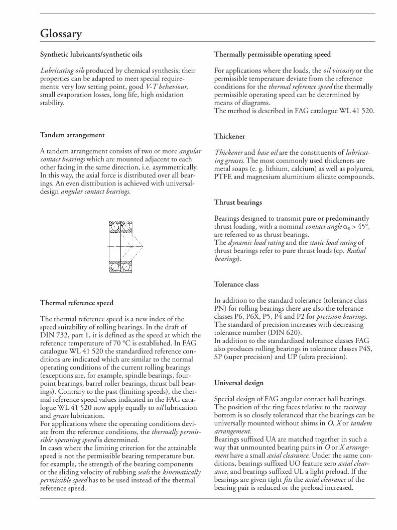
Tandem arrangement
A tandem arrangement consists of two or more angularcontact bearings which are mounted adjacent to eachother facing in the same direction, i.e. asymmetrically.In this way, the axial force is distributed over all bear-ings. An even distribution is achieved with universal-design angular contact bearings.
Thermally permissible operating speed
For applications where the loads, the oil viscosity or thepermissible temperature deviate from the referenceconditions for the thermal reference speed the thermallypermissible operating speed can be determined bymeans of diagrams.The method is described in FAG catalogue WL 41 520.
Thickener
Thickener and base oil are the constituents of lubricat-ing greases. The most commonly used thickeners aremetal soaps (e. g. lithium, calcium) as well as polyurea,PTFE and magnesium aluminium silicate compounds.
Thrust bearings
Bearings designed to transmit pure or predominantlythrust loading, with a nominal contact angle a0 > 45°,are referred to as thrust bearings.The dynamic load rating and the static load rating ofthrust bearings refer to pure thrust loads (cp. Radialbearings).
Tolerance class
In addition to the standard tolerance (tolerance classPN) for rolling bearings there are also the toleranceclasses P6, P6X, P5, P4 and P2 for precision bearings.The standard of precision increases with decreasingtolerance number (DIN 620).In addition to the standardized tolerance classes FAGalso produces rolling bearings in tolerance classes P4S,SP (super precision) and UP (ultra precision).
Universal design
Special design of FAG angular contact ball bearings.The position of the ring faces relative to the racewaybottom is so closely toleranced that the bearings can beuniversally mounted without shims in O, X or tandemarrangement.Bearings suffixed UA are matched together in such away that unmounted bearing pairs in O or X arrange-ment have a small axial clearance. Under the same con-ditions, bearings suffixed UO feature zero axial clear-ance, and bearings suffixed UL a light preload. If thebearings are given tight fits the axial clearance of thebearing pair is reduced or the preload increased.
Thermal reference speed
The thermal reference speed is a new index of thespeed suitability of rolling bearings. In the draft ofDIN 732, part 1, it is defined as the speed at which thereference temperature of 70 °C is established. In FAGcatalogue WL 41 520 the standardized reference con-ditions are indicated which are similar to the normaloperating conditions of the current rolling bearings(exceptions are, for example, spindle bearings, four-point bearings, barrel roller bearings, thrust ball bear-ings). Contrary to the past (limiting speeds), the ther-mal reference speed values indicated in the FAG cata-logue WL 41 520 now apply equally to oil lubricationand grease lubrication.For applications where the operating conditions devi-ate from the reference conditions, the thermally permis-sible operating speed is determined.In cases where the limiting criterion for the attainablespeed is not the permissible bearing temperature but,for example, the strength of the bearing componentsor the sliding velocity of rubbing seals the kinematicallypermissible speed has to be used instead of the thermalreference speed.
Glossary
Viscosity
Viscosity is the most important physical property of alubricating oil. It determines the load carrying capacityof the oil film under elastohydrodynamic lubricatingconditions. Viscosity decreases with rising temperatureand vice-versa (see V-T behaviour). Therefore it is nec-essary to specify the temperature to which any givenviscosity value applies. The nominal viscosity n40 of anoil is its kinematic viscosity at 40 °C. SI units for the kinematic viscosity are m2/s andmm2/s. The formerly used unit Centistoke (cSt) corre-sponds to the SI unit mm2/s. The dynamic viscosity isthe product of the kinematic viscosity and the densityof a fluid (density of mineral oils: 0.9 g/cm3 at 15 °C).
Viscosity ratio k
The viscosity ratio, being the quotient of the operatingviscosity n and the rated viscosity n1, is a measure of thelubricating film development in a bearing, cp. factora23.
Viscosity-temperature behaviour (V-T behaviour)
The term V-T behaviour refers to the viscosity varia-tions in lubricating oils with temperature. The V-T be-haviour is good if the viscosity varies little with chang-ing temperatures.
Wear
The life of rolling bearings can be terminated, apartfrom fatigue, as a result of wear. The clearance of aworn bearing gets too large. One frequent cause of wear are foreign particles whichpenetrate into a bearing due to insufficient sealing andhave an abrasive effect. Wear is also caused by starvedlubrication and when the lubricant is used up. Therefore, wear can be considerably reduced by pro-viding good lubrication conditions (viscosity ratiok > 2 if possible) and a good degree of cleanliness inthe rolling bearing. Where k ≤ 0.4 wear will dominatein the bearing if it is not prevented by suitable addi-tives (EP additives).
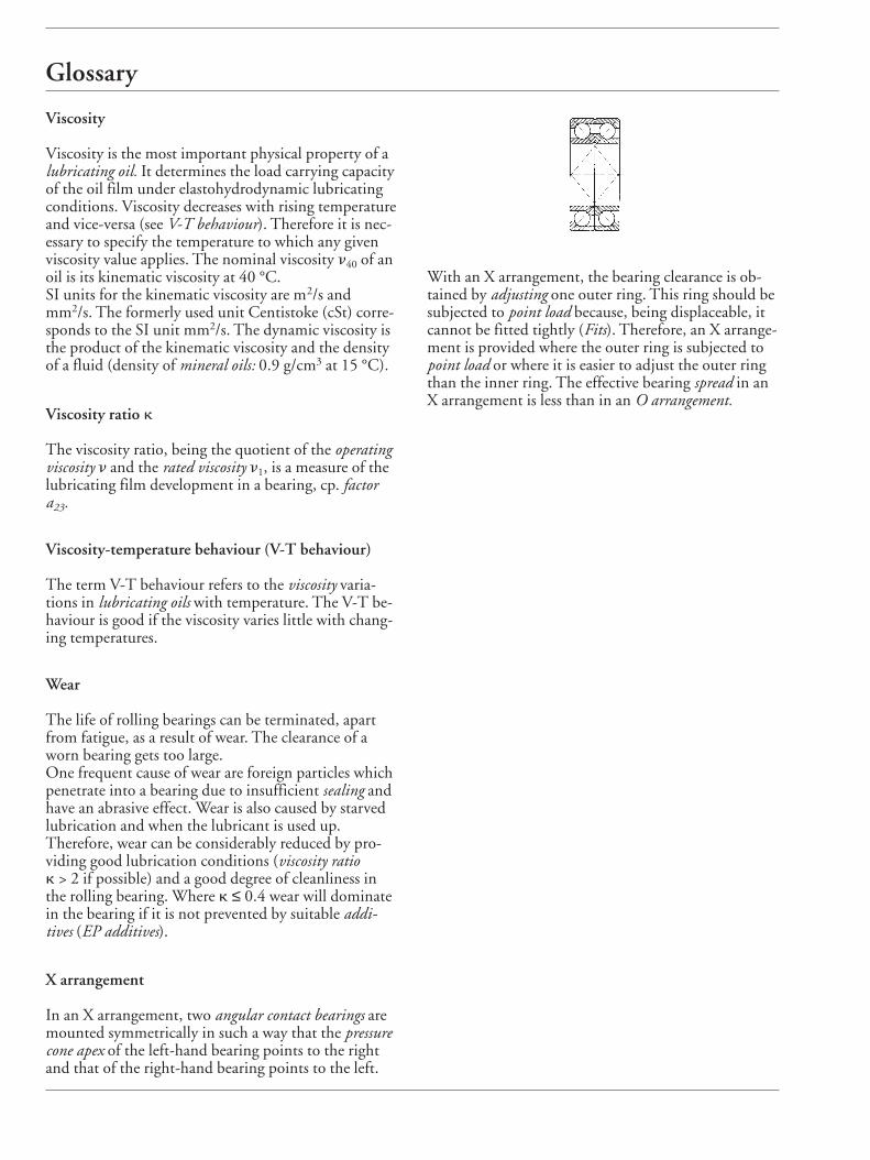
X arrangement
In an X arrangement, two angular contact bearings aremounted symmetrically in such a way that the pressurecone apex of the left-hand bearing points to the rightand that of the right-hand bearing points to the left.
With an X arrangement, the bearing clearance is ob-tained by adjusting one outer ring. This ring should besubjected to point load because, being displaceable, itcannot be fitted tightly (Fits). Therefore, an X arrange-ment is provided where the outer ring is subjected topoint load or where it is easier to adjust the outer ringthan the inner ring. The effective bearing spread in anX arrangement is less than in an O arrangement.