pcu 8510 / 8520 - pitri-tv.ru filespecial features of the polytron compact headends are...
TRANSCRIPT

PCU 8510 / 8520
User manual
MADE IN GERMANY
0901842 V1

2
Contents
1. Mounting and safety instructions 3
2. General information 5
3. Description 5
4. Scope of delivery 5
5. Input circuit 5
6. Assembly 6
6.1. Grounding 6
7. Installation 7
7.1. Pre-programming 7
7.2. Input level 8
7.3. Output level 8
8. General programming 8
8.1. Software installation 8
8.1.1. Installation of the driver 9
8.1.2. Installation of the programming software 10
8.2. Programming of the device parameters 10
8.2.1. Input parameters SAT reception 11
8.2.2. Output parameters DVB-C 12
8.2.3. Output parameters DVB-T 14
8.3. Function >Service list< (Program list) 15
8.3.1. Delete and add Services (Programs) 16
8.3.2. LCN function 18
8.3.3. SID-Remapping – manual assignment of Service-IDs 19
8.3.4. NIT-processing (Network Information Table) 22
8.4. Storage of the programming 33
8.4.1. Storage of settings 33
8.4.2. Loading of settings 33
8.5. LAN function 34
8.6. Diagnostics 35
8.7. LED key 35
8.8. Firmware update 36
8.8.1. Firmware version overview 36
8.8.2. Changing the output signal 37
8.8.3. Password function 38
9. Application examples 40
10. Technical data 42

3
Mounting and safety instructions 1.

4
ATTENTION
This module contains ESD components! (ESD = Electrostatic Sensitive Device). An electrostatic
discharge is an electrical current pulse, which can flow also through an electrically insulated material, when triggered by large voltage difference.
To ensure the reliability of ESD components, it is necessary to consider their most important handling rules:
Electrostatic sensitive components can be processed only on electrostatic protected area (EPA)!
Pay attention permanently to potential equalization (equipotential bonding)!
Use wrist straps, approved footwear for personnel grounding!
Avoid electrostatically chargeable materials such as normal PE, PVC, polystyrene!
Avoid electrostatic fields >100 V/cm !
Use only labeled and defined packing and transportation materials!
Damage caused by faulty connections and / or improper handling are excluded from any liability.
Waste disposal
Electronic equipment is not household waste but should be properly disposed on electrical and electronic
equipment waste - in accordance with Directive 2002/96/EC OF THE EUROPEAN PARLIAMENT AND COUNCIL.
Please take this device at the end of its use for proper disposal at the designated public collection points.
WEEE-Reg.-Nr. DE 51035844
Changes to the NIT table(s) first become effective after closing the PC software.
Please wait approx. 1 min. after closing the PC software until the changes become
effective in all relevant systems.

5
General information 2.
The new compact HDTV-headends from the PCU 8000-series are implementing signals from 8 satellite
transponders into 8 DVB-C or DVB-T channels, optionally.
An intervention in the transport stream is possible to delete such programs, to adapt NIT / ONID data or to
implement a program assignment using the LCN function. The possibility of allocating new TS IDs or SIDs via
the remapping function completes the practical functionality of the PCU 8000-series.
Special features of the Polytron compact headends are temperature-controlled fans as part of the Polytron
long-life concept and the intuitive programming of devices using the standard built -in control options via USB
and LAN. All models of the PCU compact headend series can be combined via a common NIT table.
The quality of every single “Made in Germany” headend of the PCU 8000-series is ensured by a 24 hours test
run prior to delivery.
Description 3.
The compact headend PCU 85x0 from POLYTRON converts 8 input signals (DVB-S/S2) into DVB-C/DVB-T
output signals. For example, it’s conceivable to use the device as free-to-air basic supply in a small boarding
house or hotel, because around 40 programmes of 8 transponders are already available. The headend can
easily and quickly be programmed via the USB interface. No knowledge whatsoever the assigning and
administration of IP addresses is required for this. The selected settings can be printed and saved and also
transferred to other devices with a USB-stick. Due to the integrated LAN connection, it is possible to remotely
control all parameters. The headend works in the frequency range 112 to 860 MHz and converts the selected
satellite transponders completely including the additional services Teletext, EPG etc. The output is also
suitable for adjacent channels and has a level of 90 dBμV. The PCU 85x0 is equipped with an energy-saving
switching power supply which also serves for the supply of the LNB (tuner 1 and tuner 2). The supply voltages
can be switched on or off by means of jumpers.
PCU 8510 = DVB-C at the output
PCU 8520 = DVB-T at the output
Scope of delivery 4.
1 x PCU 85x0
1 x Power cable
1 x USB-cable
1 x USB-Stick (Programming software)
1 x LAN patch cable
1 x Operating instructions
1 x Installation accessories
Input circuit 5.
In the PCU 85x0, signals are directly fed to the input tuners. There are 8 ports for SAT signals. As factory
default, there is an additional 12V DC input for LNB supply on the SAT input tuner 1 and tuner 5. This input
can be switched off using the jumpers J1 and J2. The operating states are indicated by LEDs.

6
Assembly 6.
The installation of the compact headend must take place in a well ventilated room. The ambient temperature
must not be more than 45°C. It must be ensured that the air can circulate through the ventilation holes. There
must be at least 15 cm of space around the device, so that the air can circulate properly. The plug must be
pulled from the socket before installation or work on the cabling.
Grounding 6.1.
The device must be grounded in accordance with EN 60728-11.
- Strip approx. 15 mm of the cable insulation of the grounding cable (4mm2).
- Push stripped end under the earth screw and tighten the screw.
J1 > 12V on/off
Sat-Tuner 1
J2 > 12V on/off
Sat-Tuner 5
15 cm
15 cm

7
Installation 7.
Connection of the Input Signals
Connect SAT signals directly or via splitter to the sat tuner inputs.
At the SAT input tuner 1 and tuner 5 is a 12 V DC voltage for the LNB power supply's.
Please note that the consumption of each input must not exceed 250 mA.
Pre-programming 7.1.
The inputs and outputs of the device are pre-programmed ex-factory with a German standard frequency
allocation. A separate supplementary sheet with the pre-programming is enclosed with the device.
Tuner 1
LNB-DC
Tuner 5
LNB-DC

8
Input level 7.2.
In order to ensure flawless reception, make sure that the level at the inputs is between 50 and 80 dBµV.
If the input level is too high, an attenuator is to be used.
When receiving digital signals it is advantageous to have a lower input level instead
of an excessively high one.
If the input level is too high, an attenuator is to be used.
Output level 7.3.
Upon delivery, the output level is 90 dBµV. This can be changed via the device programming. There is an
output level reduced by 20 dB at the TEST socket.
General programming 8.
After the mains cable is connected, the device runs through an internal routine and all 4 channels are set with
the previously stored data. During this, the status LED next to the USB socket flashes green.
Only after the status LED is continuously green or orange, contact is possible between PCU 85x0 and
PC/Laptop.
Software installation 8.1.
Download the software package from the homepage www.polytron.de (satc12_Vxxx.zip) and unzip in the
directory of your choice (e.g. C:\ PCU 85x0).
The software can also be loaded from the enclosed USB stick.
Test -20 dB Output 112…860 MHz

9
8.1.1. Installation of the driver
Start Instal_driver.cmd
Follow the instructions on the screen.
In some first installations the following dialog can appear. This depends on the operating system. Carry out
the following instructions and select the selection fields:
no, not this time
next
install Software automatically
next
If this notice is displayed:
Continue the installation

10
The installation of the driver software is now complete.
8.1.2. Installation of the programming software
Install the software by starting the "Setup.exe" program in the desired folder.
Follow the instructions on the screen.
Close the screen displays once the installation has ended.
After the installation of the programming software on the PC, the PCU 85x0 can be
connected to the PC with an USB cable.
Only connect the device
to the PC once the
software installation has
been completed.
Programming of the device parameters 8.2.
Start the program – SATC12 –
Click on Menu at the top left
The following menu points are available:
Program Menu
Diagnostic
Firmware Update
Exit
Select Program Menu: all adjustments of the input and output parameters are carried out here. After calling on
the menu, all 8 channels and the respective adjusted parameters are displayed.
The software was installed for
the following hardware
finish
USB socket

11
In the top part of the menu, the device data is displayed, such as type, serial number, hardware version and the
software states for CPU and FPGA (software is up-to-date, if the corresponding field is highlighted in green).
8.2.1. Input parameters SAT reception
DVB > Input signal
Input signal indication
Auto > LO. -frequency
TP > Transponder frequency
Enter transponder frequency
SR > Symbolrate
AUTO sets the required
frequency automatically.
Can however be set to 09750 ,
10600 or another
OTHER frequency.
Search >
After the button Search has
Enter symbol rate
Tuner Locked
If the tuner finds the transponder
Tuner Locked is displayed in the upper
field.
been activated, the data is
accepted and the desired
transponder is set.

12
Receiving Conditions
The quality of the input signal can be
evaluated using the bit error ratio
BER and the signal-to-noise ratio SNR .
8.2.2. Output parameters DVB-C
OP > Operating Mode
Normal> normal mode
Single > single carrier for
level measurement
with an analog antenna measuring device
Zero > digital channel with
content 0 (constant
level without fluctuations)
F > Output Frequency
Frequency freely selectable.
It is recommended to stick to the corresponding TV standard channel spacing.
The frequency of the channel middle is set. (e.g. channel 21, 410- 478 MHz, set 474 MHz)
BW > Bandwidth
Choose bandwidth depending on output frequency between 7 MHz and 8 MHz
QM > QAM Mode
Setting of the possible QAM mode (16, 32, 64, 128, 256) dependent on the data rate of the input
transponder.

13
SR > Symbol Rate
Up to 7.200 kilo symbols/ sec.
(used setting in cable networks: 256 QAM / SR 6.900).
SP > Spectrum
Normal > normal mode
Inverted > Useful signal can be
inverted in its spectral position. Inversion is only necessary in
exceptional cases.
On OFF > Switching Off
Output Channel
If not all 4 output channels are to be assigned, each channel can be switched off individually with
OFF.
ATT > Output Level
The output level at the output is 90dBµV and can be weakened in each channel by up to 12 dB in
1dB steps.
Set > Accept Programming
After the setting of all parameters press the Set button. With this, the adjusted data is accepted.
Repeat steps for other channels.
N.B.: The DVB-C / QAM receivers must be programmed in
accordance with the set parameters (search).

14
8.2.3. Output parameters DVB-T
OP > Operating Mode
Normal> normal mode
Single > single carrier for
level measurement
with an analog antenna measuring device
Zero > digital channel with
content 0 (constant
level without fluctuations)
F > Output Frequency
Frequency freely selectable. It is recommended to stick
to the corresponding TV standard channel spacing. The frequency of the channel middle is set.
(e.g. channel 21, 410- 478 MHz, set 474 MHz)
BW > Bandwidth
Choose bandwidth depending on output frequency between 7 MHz and 8 MHz
CR > Code Rate
Setting of the possible Code rate (1/2, 2/3, 3/4, 5/6, 7/8)
GI > Guard Intervall
Setting of the possible Guard intervall (1/4, 1/8, 1/16, 1/32)
CM > Carrier Modulation
Setting of the possible carrier (2k, 8k)

15
QM > QAM Mode
Setting QAM mode
(16, 32, 64)
SP > Spectrum
Normal > normal mode
Inverted > Useful signal can be
inverted in its spectral position. Inversion is only necessary in exceptional cases.
On OFF > Switching Off
Output Channel
If not all 4 output channels are to be assigned, each channel can be switched off individually with
OFF .
ATT > Output Level
The output level at the output is 90dBµV and can be weakened in
each channel by up to 12 dB in 1dB steps.
Set > Accept Programming
After the setting of all parameters press the Set button. With this, the adjusted data is accepted.
Repeat steps for other channels.
N.B.: The DVB-T / COF receivers must be programmed in
accordance with the set parameters (search).
Function >Service List< 8.3.
If certain services within a transponder are not desired at the output, they can be removed.

16
8.3.1. Delete and add services (programs)
Clicking on this button opens the following window. The list of services available at the input is shown on the
left. On the right, one can see the services contained in the output signal.
The button Service List is only active if the tuner is locked.
If the data rate at the input is higher than the data rate that is possible at
the output due to the set parameters an error message appears and the
button for the Service List turns red. In this case, a reduced selection of
the desired services must be made.
If the data rate at the output is too high,
the word "Overflow" appears in the field
“Rem. Bitrate”. This means that the data
rate is too high for the set parameters,
and services must be removed.
Undesired services can of course also be
deleted if there is no overflow.
The field Bitrate is marked by colors.
Green means: The remaining bitrate is higher than 10000 kSym. Yellow means: The remaining bitrate is
less than 10000 kSym. Red means: The remaining bitrate is less than 5000 kSym.
Overflow means: The data rate is too high in accordance to the adjusted DVB-C or DVB-T parameters.
Ov erflow

17
By clicking on a service in the input list and clicking on the command Add, this service is added to the output
list (also double-clicking on a service in the input list automatically adds it to the output list).
Clicking on a service in the output list and clicking on the command Remove removes this service from the
output list (also double-clicking on a service in the output list removes the service automatically).
By single-clicking on the Save/Back button, the output list is saved and the window is automatically closed.
If you want to choose only a few services from a transponder containing many services, you can first click on
Remove ALL and then select the required services.
The still available data rate is
shown in the field “Rem. Bitrate”.
This should be at least 5.000 kSym.

18
8.3.2. LCN function for the allocation of program positions
Precondition is that the TVs/receivers support LCN.
Click on LCN / Remap Settings.
The CHANNEL index indicates the
channel strip that contains the channel.
In the LCN column, you can enter the desired
program position. These programs are then sorted in
order in the table. Programs that didn’t get a position
code will follow behind the marked programs.
Storing the
LCN settings
PCU 8520

19
8.3.3. SID-Remapping – manual assignment of Service-IDs
With the functionality SID-remapping new programs can be transmitted without retuning the receivers.
Selected services are assigned with a new Service ID = (SID).
Important: Please ensure that a unique SID is assigned to the programs which are changed.
The max. number of programs to be remapped must be assigned and scanned at first installation (some
may be used as „placeholder“).
- changes to less numbers of programs -> no new channel search is needed
- changes to higher numbers of programs -> new channel search is required
Important: If service-remapping should be applied, this adjustment has to be done before creating the
combined NIT.
Settings:
Click on the tab NIT / LCN.
Afterwards click on LCN / Remap Settings.
Example 1 (continuous allocation of Service IDs over all transponders):
PCU 8520
PCU 8520

20
Example 2 (continuous allocation of Service IDs for every transponder):
Service IDs are entered manually. We recommend to use hexadecimal values within the range of F001 and FFFE.
Important: The allocation of the Service ID can be continuously (example 1).
A service is referenced inside of a transponder by the unique pairing of ONID/TSID/SID.
That’s why the same SID can be used again in another transponder (example 2).
Within one transponder the same SID must not be used twice.
Click Save to apply the changes.
Indication of fault case (the same SID is used twice for transponder 1):
Error correction: By manually change of the SID and Save.

21
Indication for the case, that instead of originally 6 programs of transponder 1 only 4 programs were fed into
after changing:
Important: A new channel search is not required for this example but the picture on the receivers site will remain
„black“ for the 2 services with the SID F005 and F006.
Add LCN numbers:
Enter the corresponding LCN numbers manually.
Click Save to apply the changes.

22
8.3.4. NIT-processing (Network Information Table)
NIT stands for a transponder table which includes information for direct reception of digital programmes.
NIT-processing requires advanced skills of DVB-standards!
The combined NIT includes all relevant data of all connected devices and contains information about all
receivable programmes in the network.
Important: Place output channels within a combined NIT onto the lower frequency range, if possible. Many
receivers start scanning at the lower end of the band ensuring that the combined NIT is found at
first. This is particularly the case if existing systems with devices from other manufacturers will
be upgraded and the combined NIT is missing.
Important: The skilled employee should create a precise system and programming plan before
installation/programming.
Important: If service-remapping should be applied, this adjustment has to be done before
creating the combined NIT.
Process scheme:
2. create a combined NIT using the
individual device parameters
3. upload the combined NIT upon
all devices, separately
4. in case of later changes:
- set all devices separately
- create a new combined NIT
- upload the combined NIT upon all devices, separately
1. set all devices separately, store the
parameters and document them

23
Settings:
Click on the tab NIT / LCN.
Afterwards click on NIT Mode to determine which NIT should be used.
No NIT: No NIT will be sent (for special applications, not according to DVB-standard).
Device NIT: A valid NIT will be sent automatically for the actual device (factory setting).
Combined NIT: A cross-device NIT will be sent. Assumed, that the user has created and stored a cross-device NIT
onto the device.
Click Save to apply the change.
PCU 8520
PCU 8520

24
Device NIT:
After clicking on Device NIT following screen window appears:
Note: Be aware of the plausibility and/or overlaps of the data before being entered!
Network ID: DVB-C at the output -> factory setting FF01 (modification possible)
DVB-T at the output -> factory setting 3002 (modification possible)
Network Name: Can be defined by the user.
Country: DVB-C at the output -> factory setting Original (modification possible, by choosing Original the
received ONID from the satellite will be used)
DVB-T at the output -> factory setting Germany (modification possible)
The country setting should be the same as the receiver settings.
TSID New: If using the dual modulators, the original TSID is assigned twice. Therefore a new TSID has to be
created in this box. We recommend to use hexadecimal values within the range of F001 and FFFE.
Click Save to apply the changes.
The pairs of ONID and TSID are
identifying the transponder.
PCU 8520

25
Combined NIT:
The settings of the individual devices must be stored before creating the combined NIT.
By choosing the menu point Settings it is possible to save existing settings on a PC/Laptop or to load it from a
PC/Laptop.
With the menu point Save Settings it is possible to save the programming onto the PC/Laptop.
A folder and a file name (e.g. object) has to be entered. The file name must retain the ending .c12!!
The settings are also saved to an *.rtf-file. This file format can be opened, edited and printed with e.g. Microsoft
Word, Open Office or WordPad.
Additionally to that a *.hdb-file is created, which is needed to create a combined NIT.
All three files are located in the predetermined directory.

26
After selecting Combined NIT the screen window below appears:
By the NIT tab the individually devices could be combined.
1. Search the folder containing the setting files of the individual devices and select it.
2. Double-click on the required *.hdb-files.
3. The selected files will be listed under Files to Combine and can be deselected by double-click, if desired.
4. If a combined NIT already exists, press button Open NIT to load it from the PC/Laptop.
5. Download of a stored NIT-table from the headend.
6. Click on Create Combined NIT after entering and checking all data to create the combined NIT. This NIT
will be stored in a folder on the PC/Laptop.
1.
2.
3.
4.
5.
6.
PCU 8520

27
Click on the TS-Data tab for showing the transport stream-data of the combined NIT.
This user interface allows to check the programming data and to add an external output channel
(DVB-C = QAM or DVB-T = COFDM) to the list.
The plausibility check of the pre-programmed data runs automatically.
Existing plausibility problems and overlaps will be highlighted with coloured background (see example
above). A few combinations ONID/TSID of the device 1 and 2 (Anlage1 / 2) in the example above are the
same, which must be avoided within a network.
Important: Set all devices separately first. Afterwards create a new combined NIT and upload the
combined NIT upon all devices, separately!
Note: At the user interface only manual added entries can be modified!
Error message

28
Adding of an external output channel (e.g. additional modulator) via the TS-Data tab. Click on the tab
Add QAM Channel (DVB-C) or Add COFDM Channel (DVB-T). Following menu appears:
Note: Be aware of the plausibility and/or overlaps of the data before being entered!
Headend ID: Can be defined by the user. Should be documented for later reference.
Channel: Set the individual playback channel.
Frequency: Enter the frequency of the output channel.
QAM-Mode: Select the relevant QAM-Mode.
Symbolrate: Define the required symbol rate.
ONID / TSID: Enter the ONID and the TSID. We recommend to use hexadecimal values within the range of F001
and FFFE.
Click Save to apply the changes.

29
The data of the added output channel will be shown after storing and after the plausibility and overlaps
checks have been done:
Note: Manually added output channels will be displayed with a white background.
The functions Edit and Delete are only available for manually added output channels.
Click on the corresponding line to activate the boxes.
Click on the line to
activate the boxes

30
By the LCN-Data tab the corresponding data of the combined NIT will be shown.
Click on Add Service to add LCN to the “manually added” channels.
Following input mask appears:
Note: Be aware of the plausibility and/or overlaps of the data before being entered!
Headend ID: Select the added device.
Channel: Set the individual playback channel.
Service Name: Can be defined by the user.
Service ID: Enter a Service ID. We recommend to use hexadecimal values within the range of F001 and FFFE.
Service Type: Choice between the options TV and Radio.
LCN: Determination of the program number in the LCN-system.
Click Save to apply the changes.

31
Note: Manually added output channels will be displayed with a white background.
The functions Edit and Delete are only available for manually added output channels.
Click on the corresponding line to activate the boxes.
The plausibility check of the pre-programmed data runs automatically.
Existing plausibility problems and overlaps will be highlighted in coloured background (see example above). In the example above two program numbers in the LCN-system are the same, which must be
avoided within a network.
Error correction for the example above: Click on the LCN-program number of the line with the white
background (HDMI1) and then click on Edit. Change the LCN-program number in the input mask
accordingly and store the setting by click on Save.
Click on the line to
activate the boxes
Error message

32
Using the NIT tab, finally upload the combined NIT to the headends.
The button Upload NIT to Headend is now active. After clicking on this button the created „Combined NIT“ is
transferred to the device and transmitted to the output channels.

33
Storage of the programming 8.4.
It is possible to save existing programming on a PC and/or to load it from a PC.
Program combinations can thus be archived.
The main program is opened
with the menu point
Settings
8.4.1. Storage of settings
With the menu point
Save Settings
it is possible to save the programming onto the
PC. A directory and file name
(e.g. object) are to be entered for this.
The file name must retain the ending .c12!!
The settings are also saved in an rtf-file. This file format can be opened, edited and printed with e.g.
Microsoft Word, Open Office or WordPad.
8.4.2. Loading of settings
With the menu point
Load Settings
it is possible to load existing programming
from the PC onto a PCU 85x0.
For this, the desired file name is to be
selected and opened in the register.
The date is automatically loaded.

34
LAN function 8.5.
Click on Program Menu to open the programming
environment. The basic settings are loaded and the
user interface is started.
The PCU 85x0 possesses the IP address:
192.168.1.227 as a standard setting.
If the system is used in a network with a different
network address, the IP address of the PCU 85x0
must be accordingly altered.
This change is carried out under the menu point
LAN-Control.
Example:
The PC operated in the network has the following settings:
IP address: 192.168.010.068
network share host share
The IP address of the PCU 85x0 must only differ in the last block
(host share) compared with that of the connected PC. The figures
0, 255 and all figures already used are not permitted!
Example IP address: 192.168.010.100
All changes are saved with Save.
Please note:
The listed IP addresses are intended as examples.
All addresses must be adapted to the network at the location.
If this information is not known, the responsible
IT specialist should be contacted!
The progress of saving is displayed on the bar diagram.
This process can last up to a minute.

35
Diagnostics 8.6.
The "Diagnostic“ menu is for service purposes and can be helpful during error analysis by telephone on the
Hotline +49 (0)7081 1702-0. The displayed data can be updated with REFRESH.
Menu Header Display:
Actual Operating Temperature: approx. current ambient temperature
Total Operating Hours: operating hours
Maximum Operating Temperature: maximum measured ambient temperature
Critical Operating Hours: operating hours at ambient temperature of over 45°C
The temperatures shown only correspond to the actual values in the case of correct , vertical installation with a
closed housing cover.
LED key 8.7.
a.) LNB green: 12V output voltage
off: no output voltage
b.) Tuner green continuous: tuner logged
green flashing: tuner not logged
c.) FPGA green: configured, ready to operate
off: error
d.) RF green: output OK
off: error
e.) 12 V green: 12 V power adaptor OK
off: power adaptor error
f.) Status green: all tuners logged, ready for use
orange: different functions in programming

36
Firmware-update 8.8.
The menu “firmware update” is used to refresh the firmware of the device. In this way, the basic software of
the device will be updated.
The programming of the input and output parameters carried out under 8.2 is not influenced by this.
8.8.1. Firmware version overview
The appropriate display boxes of the firmware overview are highlighted in coloured background.
Green indicates that the firmware is up to date.
Yellow indicates that a new firmware is available.
Double click on the display box which shows the firmware, opens automatically the update menu.
If the firmware is up-to-date, following picture appears:
PCU 8520

37
8.8.2. Changing the output signal
Update by Laptop/PC:
Select menu item DVB-Output
Select menu item Change Output Standard
Choose DVB-T or DVB-C
After clicking on the Update button the
new FPGA- Software will be loaded.
The FPGA update takes approx. 15 minutes!
PCU 8520

38
8.8.3. Password function
Protection against unauthorized access to the Program-Menu.
The password function isn’t activated in the factory settings and can be switched on from
µC-SW-Version 1.31 on, like described as follows:
Klick on Extras in the upper row.
Klick on Password Settings. It appears following pop-up window, please urgently note the serial no.
because this will be needed to reset the password, if required.
Place a tick in the check-box to select Use Password.
Enter the password (min.6 / max.10 digits) in the input field Password (consisting of letters, numbers or
special characters in random sequence) and retype the password in the input field Retype Password.
By clicking on Change Password a new password can be created.
Klick on Save to store the password-settings.
Exit the program [SATC12] or go on with the settings, if necessary.
Start program [SATC12]
PCU 8520

39
After next time starting the program [SATC12] please enter the password in the input field and then click on OK to
confirm the password or click on Cancel to correct the password, if required.
Please note: In this pop-up window is no change of the password possible.
--------------------------------------------------------------------------------------------------------------------------------------
Should the password get lost or has fallen into oblivion we willingly help you relating to the generally password-reset.
For this purpose we urgently need the serial-number of the device, as already mentioned on page 1. The serial-
number you can also find on the label which is affixed on the outer side of the housing.
The generally password-reset can only be applied by POLYTRON, for this procedure you will get a new password to
reactivate the access to the device again.
By removing the tick in the check-box Use Password you can certainly also deactivate the password function, but
you will need the password to log on before.

40
9. Application examples
One satellite, all four polarization planes via splitter at
input 1-8 in conjunction with HDMI signal feed:

41
One satellite, two polarization planes via splitters at
input 1-8 in conjunction with decrypted DVB-T/T2
programs:
42
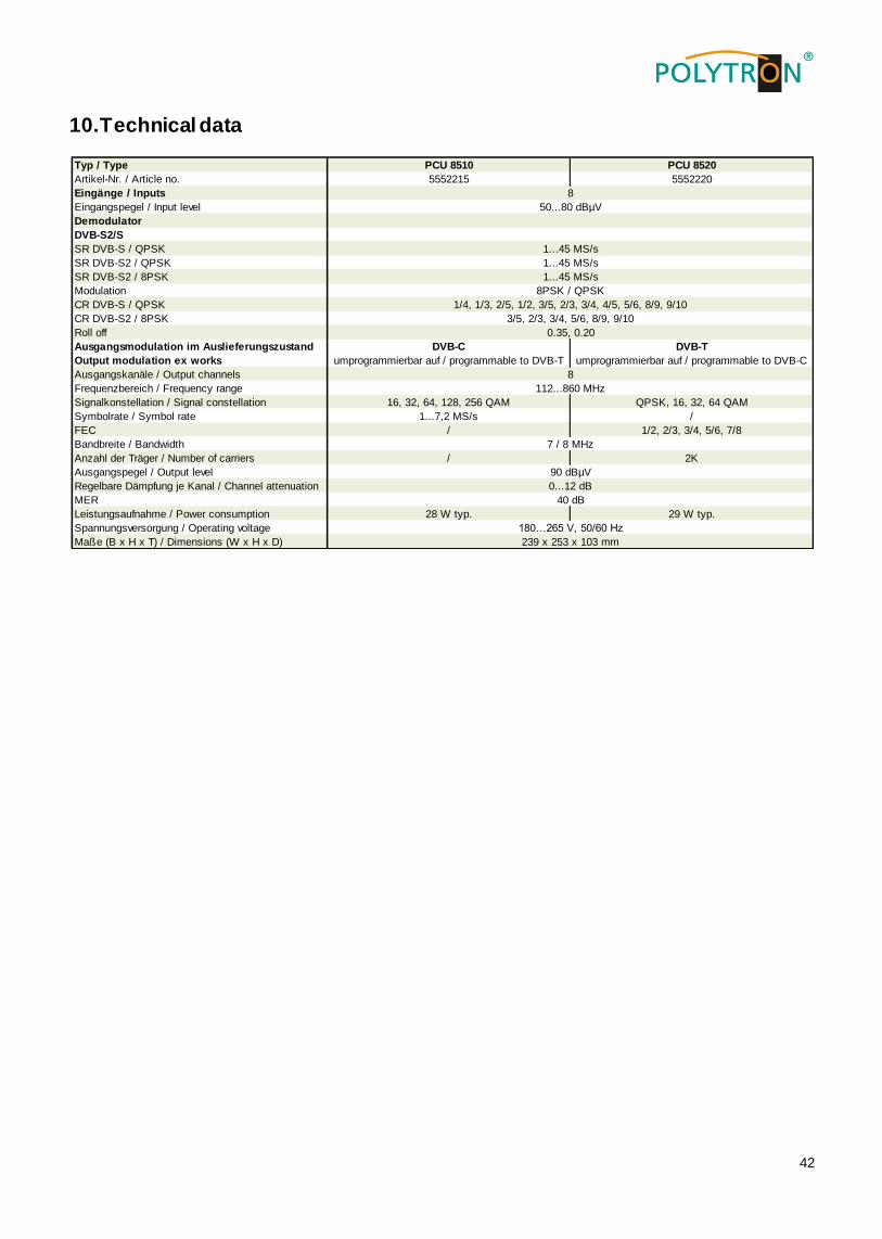
10. Technical data
Typ / Type PCU 8510 PCU 8520
Artikel-Nr. / Article no. 5552215 5552220
Eingänge / Inputs
Eingangspegel / Input level
Demodulator
DVB-S2/S
SR DVB-S / QPSK
SR DVB-S2 / QPSK
SR DVB-S2 / 8PSK
Modulation
CR DVB-S / QPSK
CR DVB-S2 / 8PSK
Roll off
Ausgangskanäle / Output channels
Frequenzbereich / Frequency range
Signalkonstellation / Signal constellation 16, 32, 64, 128, 256 QAM QPSK, 16, 32, 64 QAM
Symbolrate / Symbol rate 1...7,2 MS/s /
FEC / 1/2, 2/3, 3/4, 5/6, 7/8
Bandbreite / Bandwidth
Anzahl der Träger / Number of carriers / 2K
Ausgangspegel / Output level
Regelbare Dämpfung je Kanal / Channel attenuation
MER
Leistungsaufnahme / Power consumption 28 W typ. 29 W typ.
Spannungsversorgung / Operating voltage
Maße (B x H x T) / Dimensions (W x H x D) 239 x 253 x 103 mm
1/4, 1/3, 2/5, 1/2, 3/5, 2/3, 3/4, 4/5, 5/6, 8/9, 9/10
3/5, 2/3, 3/4, 5/6, 8/9, 9/10
0.35, 0.20
8
112...860 MHz
7 / 8 MHz
90 dBµV
0...12 dB
40 dB
180…265 V, 50/60 Hz
8
50...80 dBµV
1...45 MS/s
1...45 MS/s
1...45 MS/s
8PSK / QPSK
Ausgangsmodulation im Auslieferungszustand
Output modulation ex works
DVB-C
umprogrammierbar auf / programmable to DVB-T
DVB-T
umprogrammierbar auf / programmable to DVB-C

43
Notes

44
Polytron-Vertrieb GmbH
Postfach 10 02 33
75313 Bad Wildbad
Germany
Zentrale/Bestellannahme
H.Q. Order department + 49 (0)7081 1702 - 0
Technische Hotline
Technical hotline + 49 (0)7081 1702 - 0
Telefax + 49 (0)7081 1702 - 50
Internet http://www.polytron.de
Email [email protected]
Technische Änderungen vorbehalten
Subject to change without prior notice
Copyright © Polytron-Vertrieb GmbH