pcs oe catalog rev5 - powertrain control solutions · pdf file• front wheel drive gm...
TRANSCRIPT

For more information, please visit www.powertraincontrolsolutions.com
OEM CATALOGPCS product offerings for vehicle manufacturers.
• 100% Factory New Transmissions • Interchangeable Bellhousings • Powertrain Electronics • Shifters • Valve Bodies

See page 2-3.
See pages 10-14.
Transmission Controllers• Controls nearly all electronic automatic transmissions from GM, Ford, Chrysler, Allison,
ZF, VW, and more• Body control functionality including engine shut down, warning indicators, built into the
transmission control module
See page 7.
Parking Brake• Disc parking brake• Interchangeable extension housings to use with other confi gurations• Mounts directly to the GM 4L60/70
100% Factory New Transmissions• Rear wheel drive GM 4L60, 4L70, 6L50, 6L80, 6L90, 8L90• Front wheel drive GM 6T40, 6T70, 6T75
OVERVIEW
NEED TECHNICAL ASSISTANCE?
Phone: +1 (804) 227-3023Email: [email protected] ([email protected])
Technical and sales personnel are available from 9:00 a.m. to 5:00 p.m. EST, Monday through Friday. PCS is closed on weekends and holidays.
TRANSHELP.US
IMPORTANT NOTICEThe information in this catalog has been compiled to help provide general information about our products. Photographs and illustrations throughout this catalog may contain product that could vary from current production parts.
We strongly recommend contacting us to verify products will work with your application and if there are any additional requirements before purchasing. We assume no liability for errors contained herein. We reserve the right to change products and kits at any time.
We assume no liability for errors made in product selection or installation errors made by end users. Please contact us for any questions or visit our website for the most up-to-date information.
TABLE OF CONTENTS
Intuitive Designs. | 1+1 (804) 227-3023
Transmissions .........................................................................................................................................................................................................................2 - 7
New Transmissions ............................................................................................................................................................................................................ 2
Transmission Reference ..................................................................................................................................................................................................... 3
4LHD/HDX Transmissions .............................................................................................................................................................................................4 - 5
C6 Replacement ................................................................................................................................................................................................................. 6
Parking Brakes ................................................................................................................................................................................................................... 7
Engines.......................................................................................................................................................................................................................................... 8
Smart Diesel ....................................................................................................................................................................................................................... 8
Control Modules ........................................................................................................................................................................................................................... 9
Power Distribution ............................................................................................................................................................................................................. 9
CAN Switch Panels ........................................................................................................................................................................................................... 9
RFID Driver Authorization Module ...................................................................................................................................................................................... 9
Transmission Controllers ...................................................................................................................................................................................................10 - 14
Block Diagram ................................................................................................................................................................................................................. 10
Application Chart ............................................................................................................................................................................................................. 11
Controller Overview .......................................................................................................................................................................................................... 12
OEM Controllers ........................................................................................................................................................................................................13 - 14
Displays ................................................................................................................................................................................................................................15 - 17
Dash Panels .................................................................................................................................................................................................................... 15
Gear Indicators ................................................................................................................................................................................................................ 16
Data Logging & Diagnostics ............................................................................................................................................................................................. 17
Shifters .................................................................................................................................................................................................................................18 - 19
Gear Select Module .......................................................................................................................................................................................................... 18
Paddle Shifters ................................................................................................................................................................................................................. 19
Data Acquisition ..................................................................................................................................................................................................................20 - 21
CAN Modules ................................................................................................................................................................................................................... 20 Sensors ............................................................................................................................................................................................................................ 21
Capabilities ..........................................................................................................................................................................................................................22 - 24
Engineering ...............................................................................................................................................................................................................22 - 23
Manufacturing ................................................................................................................................................................................................................... 24
About PCS ................................................................................................................................................................................................................................... 25
TABLE OF CONTENTS

2 | Innovative Solutions. www.powertraincontrolsolutions.com
GM 4L60/65/70E GTP 4L80/85E GM 6L50 GM 6L80 GM 6L90 6T40/45 6T70/75 8L90
Type
Four speed, longitudinal rear-wheel drive,
electronically controlled, automatic overdrive
transmission with torque converter clutch
Four, fi ve, or six speed, longitudinal rear-wheel drive,
electronically controlled, automatic overdrive transmission with torque
converter clutch and optional electronic engine braking
Six-speed RWD/AWD, electronically controlled
automatic overdrive transmission w/ torque
converter clutch, Clutch-to-clutch architecture, w/ Integral Electro/Hydraulic
Controls Module
Six-speed RWD/4WD/AWD, electronically controlled automatic
overdrive transmission w/ torque converter
clutch. Clutch-to-clutch architecture, w/ Integral
Electro/Hydraulic Controls Module
Six-speed RWD/4WD/AWD, electronically controlled automatic
overdrive transmission w/ torque converter
clutch. Clutch-to-clutch architecture, w/ Integral
Electro/Hydraulic Controls Module
Six-speed FWD/AWD, electronically controlled
automatic overdrive transmission w/ torque
converter clutch. Clutch-to-clutch architecture,
w/ Integral Electro/Hydraulic Controls
Module
Six-speed FWD/AWD, electronically controlled
automatic overdrive transmission w/ torque
converter clutch. Clutch-to-clutch architecture,
w/ Integral Electro/Hydraulic Controls
Module
Eight speed RWD / AWD, electronically controlled automatic
overdrive transmission with torque converter
clutch. Clutch-to-clutch architecture, with
external transmission control module
Engine Range 2.2L – 6.2L Gasoline/Diesel 4.8L – 6.0L Gasoline, 6.5L – 6.6L Diesel
2.0L - 4.6L Gasoline, 2.9L Diesel
4.4L SC, 6.0L, 6.2L Gasoline
6.2L - Gasoline, 6.6L Diesel
1.4L - 3.0L Gasoline/Diesel
3.6L - 4.6L Gasoline/ Diesel
6.2L - Gasoline, 6.6L Diesel
Maximum Engine Torque
4L60E: 350 lb-ft (475 Nm)4L65E: 380 lb-ft (515 Nm)4L70E: 400 lb-ft (542 Nm)
4L80E: 440 lb-ft (597 Nm)4L85E: 460 lb-ft (624 Nm) 332 lb-ft (450 Nm) 487 lb-ft (660 Nm) 531 lb-ft (720 Nm) 232 lb-ft (315 Nm) 295 lb-ft (400 Nm) 635 lb-ft (860 Nm)
Maximum Gearbox Torque
4L60E: 610 lb-ft (827 Nm)4L65E: 670 lb-ft (908 Nm)4L70E: 670 lb-ft (908 Nm)
885 lb-ft (1200 Nm) 479 lb-ft (650 Nm) 664 lb-ft (900 Nm) 885 lb-ft (1200 Nm) 295 lb-ft (400 Nm) 380 lb-ft (515 Nm) 738 lb-ft (1000 Nm)
Available Gear Ratio 1,2,3,4,5*,6* 7*,8*,R) * When available
3.059, 1.625, 1.0, 0.696, -2.294
2.48, 1.48, 1.00, 0.75, -2.072.48, 1.86, 1.48, 1.00,0.75, -2.07
2.98, 1.57, 1.00, 0.75, -2.462.98, 2.24, 1.57, 1.00, 0.75, -2.46
2.98, 2.24, 1.57, 1.18, 1.00, 0.75,-2.46
4.065, 2.371, 1.551, 1.157, 0.853, 0.674,
-3.200
4.027, 2.364, 1.532, 1.152, 0.852, 0.667,
-3.064
4.027, 2.364, 1.532, 1.152, 0.852, 0.667,
-3.064
4.584, 2.964, 1.912, 1.446, 1.000, 0.746,
2.940
4.484, 2.872, 1.842, 1.414, 1.000, 0.742,
2.882
4.560, 2.970, 2.080, 1.690, 1.270, 1.000, 0.850, 0.650, 3.820
Maximum Gross Vehicle Weight (application and axle ratio dependent)
8,600 lb (3900 kg) 18,000 lb (8165 kg) 6613 lb (3000 kg) 8600 lb (3900 kg) 15,000 lb (6803 kg) 4850 lb (2200 kg) 6400 lb (2909 kg) 13,200 lb (6,000 kg)
Maximum Gross Combined Vehicle Weight (application and axle ratio dependent)
15,500 lb (7030 kg) 22,000 lb (9979 kg) 12,505 lb (5672 kg) 14,000 lb (6350 kg) 21,000 lb (9525 kg) Application Dependent Application Dependent Application Dependent
7-Position Quadrant P, R, N, OD, D, 2, 1 P, R, N, OD, D, 2, 1 P, R, N, D, (M) P, R, N, D, (M) P, R, N, D, (M) P,R,N,D, (M) P,R,N,D, (M)
5 position ( P,R,N,D,M) protected for 6 position
(P,R,N,D,M,L)
Case Die cast aluminum, removable bell-housing Die cast aluminum
Die cast aluminum (3-piece: bell & main
w/ extension)
Die cast aluminum(3-piece: bell & main
w/ extension)
Die cast aluminum(3-piece: bell & main
w/ extension)Die cast aluminum Die cast aluminum Die cast aluminum
Shift Pattern (2) Two-way on/off solenoids(2) Two-way on/off solenoids
(3) Two-way on/off solenoids for 5/6 speed
(2) Three-way on/off solenoids
(2) Three-way on/off solenoids (2) Three-way on/off
solenoids(6) Variable bleed
solenoids(6) Variable bleed
solenoids
(6) variable force solenoids. One for
each clutch and one for TCC
Shift QualityPressure control solenoid3-2 control solenoid (some
models)Pressure control solenoid (5) Variable bleed
solenoids(5) Variable bleed
solenoids(5) Variable bleed
solenoids(6) Variable bleed
solenoids(6) Variable bleed
solenoids
(6) variable force solenoids. One for
each clutch and one for TCC
Torque Converter Clutch
Pulse width modulated solenoid control
Pulse width modulated solenoid control Variable bleed solenoid Variable bleed solenoid Variable bleed solenoid Variable bleed solenoid Variable bleed solenoid
Variable Force Solenoid ECCC, 2
path, turbine damper
Converter Size Various 310 mm 240/245/258 mm 258, 300 mm 300 mm 236 mm 246 mm 258mm ( reference )
Fluid Type DEXRON VI DEXRON VI DEXRON VI DEXRON VI DEXRON VI DEXRON VI DEXRON VI Dexron High Performance ATF
Transmission Weight
Typical Bell, 2-piece case – 2WD: 200 lb (91 kg), 4WD:
196 lb (88 kg)Wet: 254 lb (115 kg) Wet: 187 - 198 lb
(85-89 kg) Wet: 225 lb (102 kg) Wet: 240 lb (109 kg) Wet: 187 lb (85 kg) Wet: 230 - 232 lb (104 kg - 105 kg)
210 lb - 218 lb(95.5 kg - 99 kg)
Fluid Capacity (approx.)
8.8 – 11.4 qt (8.3 – 10.7 Liters)
13.5 qt (12.8 Liters)
10.1 – 11.4 qt (9.6 - 10.82 Liters)
10.2 – 12.8 qt (9.7 – 12.1 Liters)
12.3 – 13.3 qt (11.6 – 12.54 Liters) 8.5 qt (8.0 Liters) 9.5 qt (9.0 Liters) 11 qt (10.5 Liters)
Pressure Taps Available Line pressure Line pressure Line pressure Line pressure Line pressure Line pressure Line pressure c12345R Clutch
PCS offers a complete line of factory new transmissions including 4 and 6-speed RWD and FWD transmissions. Available transmissions include GM 4L60/65/70E, GM 6L50/80/90, GM 6T40/70/75, and GTP 4L80/85E. PCS can provide a turn-key solution including controller, harness, fl explate, dipstick, and more. SAE3 and SAE4 bellhousings are available. PCS can design and manufacture custom bellhousings for nearly any engine upon request.
Factory new transfer cases (manual or electric shift), extension housings and adapters are available for a complete driveline solution.
TRANSFER CASES4L70 4WD Transfer Case
TRANSMISSIONS
NEW TRANSMISSIONS

DF
BA C
E
A B C D D E F G H
Trans Model Bell Housing Main Case Case
ExtensionLength to
FlangeLength to
Shaft
Engine Block to Converter
Lug
Length to ExtensionHousing
Engine Block to Mount
Center Line to Bottom Pan
4L60/70 2WD 6.941176.30
15.421391.70
8.909226.30 N/A 30.975
786.750.85321.67
31.272794.30
24.331618.00
7.820198.60
4L60/70 4WD 6.941176.30
15.421391.70
4.433112.60 N/A 26.941
684.300.85321.67
26.795680.60
24.353618.56
7.820198.60
4L80 No separate bell housing
26.01660.65
5.495139.57
29.00 (4WD)736.71
32.1745 (2WD)817.23
0.89322.68
31.505800.23
30.672771.19
7.795198.00
6L50 6.181157.00
16.752425.50
2.28358.00
27.559700.00
26.437671.50
0.41310.50
25.216640.50
25.279642.10
9.177233.10
6L80 Fixed Yoke
6.74171.20
16.468418.30
3.4988.66
27.815706.51
29.089738.87
0.85321.67
26.699678.16 N/A 9.196
233.60
6L80 Slip Yoke
6.74171.20
16.468418.30
5.87149.10 N/A 29.962
761.060.85321.67
30.850783.60
25.595650.10
9.196233.60
6L80 4WD 6.74171.20
16.468418.30
3.58791.10 N/A 26.968
684.980.85321.67
26.795680.60
25.409645.38
9.196233.60
6L90 2WD (Duramax)
7.07179.63
17.840453.15
5.629143.00 N/A 31.439
798.560.90923.10
30.542775.78
27.480698.00
9.196233.60
6L90 4WD 6.74171.20
17.84453.15 N/A 28.559
725.4228.559725.42
0.85321.67 N/A N/A 9.196
233.60
8L90 2WD Slip Yoke N/A N/A N/A N/A 29.002
736.660.85221.64
28.227716.96
25.791655.10
8.891225.84
8L90 4WD/AWD N/A N/A N/A N/A 27.364
695.040.85221.64
26.795680.6
25.365644.27
8.891225.84
inmm*Units:
*Dimensions are for typical applications. Dimensions will vary based on converter, bell housing and application. For reference only.
NEW TRANSMISSION REFERENCE
6L80 Slip Yoke6L80 Fixed Yoke
6L90 2WD
6L504L60/70 6L80 4WD
6L90 4WD
4L80
6T70/756T40/45 8L90 Slip Yoke 8L90 4WD/AWD
TRANSMISSION REFERENCE
Intuitive Designs. | 3+1 (804) 227-3023
TRANSMISSIONS
TRANSMISSION REFERENCE

4 | Innovative Solutions. www.powertraincontrolsolutions.com
TRANSMISSIONS
4LHD/HDX TRANSMISSIONS
PCS GM 4-Speed Industrial OfferingsPCS offers two models of the GM 4-speed. Both the 4LHD and the 4LHDX models are enhanced versions of the GM 4L60/70 transmissions that have been in production since 1993.
The 4LHD is validated for gas and diesel applications up to 340 Nm (250 ft-lbs) of engine torque. Its features and enhancements over a stock 4L60 include:
• ALL NEW – Produced using GM approved production processes and quality control• Unique valve body and spacer plate calibrations for the harsh, industrial market• Abuse Protection System (APS) Valve Body Assembly (Patent Pending) to prevent operator induced
premature transmission and vehicle wear• Heat-treated stator shaft splines• 258mm Torque converter with lockup clutch• Induction and/or heat treated input/output shafts• Internal input speed sensor (shift performance/control, Diagnostics)• Internal Mode Switch (IMS)• Heavier-duty low/reverse roller clutch• 7-plate 3-4 clutch• Heavy-duty, needle-type thrust bearings• Hardened reaction sun gear shell
The 4LHDX is validated for gas and diesel applications up to 542 Nm (400 ft-lbs) engine torque. It includes all of the features described above plus:
• Induction hardened turbine shaft/output splines• Output shaft includes process improvements for longer fatigue life• 300mm torque converter with lockup clutch• Five-pinion input and reaction gear sets
Abuse ProtectionOften times the operator causes the most damage to the transmission, reducing the service life and causing costly repairs and downtime. The PCS 4-speed abuse protection valve body protects the transmission by locking out reverse engagement until the vehicle is stopped and the engine is at idle. It also prevents “neutral drops” by only engaging the forward gears when the engine is at idle.
Electronic RangeEliminate the shift cable and shift the transmission electronically with a push of a button or movement of a lever. Driver inputs can be validated based on vehicle modes and conditions so the vehicle is operated within standard operating protocols. Also eliminate transmission failures due to the shift cable not adjusted properly.
InchingThe PCS inching valve body allows the operator to move the vehicle forward or backward in small increments from an operator’s panel remotely mounted on the vehicle. This greatly reduces time when connecting to trailers or other equipment and makes the operation more effi cient for one person.
buttonandte
VALVE BODY FEATURES

Intuitive Designs. | 5+1 (804) 227-3023
TRANSMISSIONS
4LHD/HDX TRANSMISSIONS
PCS Part # Valve Body
TRN-4240 PCS Abuse Protection Valve Body
TRN-4245 PCS Abuse Protection and Inching Valve Body
PCS Part # Valve Body
TRN-4242 PCS Abuse Protection Valve Body
TRN-4247 PCS Abuse Protection and Inching Valve Body
PCS Part # Valve Body
TRN-4442 PCS Abuse Protection Valve Body
TRN-4447 PCS Abuse Protection and Inching Valve Body
PCS Part # Valve Body
TRN-4255 PCS Abuse Protection Valve Body
TRN-4257 PCS Abuse Protection and Inching Valve Body
PCS Part # Valve Body
TRN-4455 PCS Abuse Protection Valve Body
TRN-4457 PCS Abuse Protection and Inching Valve Body
Input: 258mm Torque Converter, GM V8 Bellhousing
Output: Extension housing included with longer output shaft for applications without transmission mounted parking brake or transfer case.
Input: 300mm Torque Converter, GM V8 Bellhousing
Output: Extension housing included with longer output shaft for applications without transmission mounted parking brake or transfer case.
Note: Use with GM 3.0L and 4.3L engines.
Input: 258mm Torque Converter, SAE4 Bellhousing
Output: Extension housing included with longer output shaft for applications without transmission mounted parking brake or transfer case.
Input: 300mm Torque Converter, GM V8 Bellhousing
Output:Extension housing not included. Shorter output shaft installed for applications with transmission mounted parking brake or transfer case.
Note: Use with GM 3.0L and 4.3L engines.
Input 258mm Torque Converter, SAE4 Bellhousing
Output:Extension housing not included. Shorter output shaft installed for applications with transmission mounted parking brake or transfer case.
Input: 258mm Torque Converter, GM V8 Bellhousing
Output:Extension housing not included. Shorter output shaft installed for applications with transmission mounted parking brake or transfer case.
PCS Part # Valve Body
TRN-4440 PCS Abuse Protection Valve Body
TRN-4445 PCS Abuse Protection and Inching Valve Body

6 | Innovative Solutions. www.powertraincontrolsolutions.com
TRANSMISSIONS
C6 REPLACEMENT
C6 Replacement PackageThe PCS 4LC6 transmission is a result of extensive development and engineering to provide a 100% new, electronic transmission bolt-in solution for C6 users.
The C6 replacement package includes a 100% factory new GM 4-speed transmission equipped with a bellhousing, torque converter, and extension housing that replicate a Ford C6 transmission. The bellhousing will mate directly where the previous C6 was installed. The torque converter was designed to include studs that match the Ford bolt pattern to allow use of the existing fl explate. The existing driveshaft can also be used as the PCS 4LC6 has the same overall length as the Ford C6 transmission. It does not require cross member, engine adapter, or mount modifi cation and can even utilize the existing C6 parking brake.
The package also includes a transmission controller which continuously monitors the transmission and can alert the operator if any abnormalities are detected. The transmission controller can also be programmed to customer desired shift points, gear lockouts, and any other unique operating modes.
The PCS 4LC6 also includes abuse protection, electronic range, and inching capabilities discussed on pg 4.
Description Part #GM 4-Speed with Abuse Protection and C6 packaging TRN-7645
Built for Quick InstallationFrom bellhousing to tailshaft, the PCS 4LC6 is a direct replacement for applications originally using the Ford C6.
818.13mm (32.21 in)
576.58 mm(22.7 in)
Ford C6
PCS 4LC6
Torque Converter Bolt PatternThe C6 replacement package uses the identical 11.4” 4-bolt pattern as the C6 allowing use of the existing fl explate.
476.25 mm (18.75 in) 476.25 mm (18.75 in)
PCS 4LC6Ford C6
FORD C6 AND PCS 4LC6 COMPARISON
C6 Replacement Package
Ford C6 Converter Bolt Pattern
Ford C6 Extension Housing and Output Shaft

Intuitive Designs. | 7+1 (804) 227-3023
TRANSMISSIONS
PARKING BRAKES
*Rear View
TRN7045Cable exits clockwise.
TRN7044Cable exits counter-clockwise.
CALIPER ORIENTATION
Electronic Parking BrakeIn applications where a mechanical parking brake lever is diffi cult to install or undesirable for the application, the PCS electronic parking brake module is available. The package includes a motor that connects to the cable and an electronic switch within reach of the operator. Customer specifi c switches can be adapted to the system. The parking brake control module monitors several vehicle parameters to ensure safe parking brake application and can be programmed for specifi c operating modes.
Description Part #Parking Brake Kit (Caliper sold separately) BRK-2000
Left Caliper TRN-7044
Right Caliper TRN-7045
Complete Transmission PackagesElectronic transmissions can provide signifi cant advantages over older hydraulic and hydrostatic transmissions, but their integration into the vehicle can initially appear complex and time consuming. After years of assisting vehicle manufacturers with designing and installing transmissions into drivelines, PCS has developed complete transmission packages that include everything needed for a well-engineered driveline solution. This simple solution allows the vehicle manufacturer to draw from PCS’ expertise and focus on other vehicle aspects and manufacturing. A complete transmission solution includes much more than just a transmission and torque converter. All PCS packages include vent kit, dipstick, TCU, harness, fl explate, and more.
1
20
21
22 23 2
34
5
14
151617
18
8
19
Parking BrakeThe optional disc parking brake mounts directly to the transmission. The caliper can be mounted in several positions providing clearance for transmission tunnels or exhaust. The cable can be confi gured for left hand or right hand connection to the brake caliper.

ENGINES
SMART DIESEL ENGINE
8 | Innovative Solutions. www.powertraincontrolsolutions.com
The PCS Smart Diesel is based on the GM 2.0L Turbo Diesel. This advanced, direct injection, intercooled engine features a variable geometry turbocharger, cast iron block, forged steel crankshaft, and aluminum cylinder head. The four cylinder engine uses dual overhead camshafts and four valves per cylinder for optimum effi ciency and reduced emissions.
Specifi cationsEngine Type Fam. B 2.0L Turbo Diesel engine
Bore and Stroke 83.00 x 90.40mmDisplacement 1956 cc (199 ci)Compression Ratio 16:5:1Emissions Tier IV FinalFuel System Direct InjectionEngine Mass (kg/lbs) 182 kg (401 lb)
SMART DIESEL DIMENSIONS
476.25 mm (18.75 in) 476.25 mm (18.75 in)
712.22 mm712.22 mm(28.04 in)(28.04 in)
Intermittent Power:
113 kW (151 hp) @ 4000 RPM
358 Nm (264 lb-ft) @ 2600 RPM
Three continuous power levels available (SAE J1349):
37 kW (50 hp); 178 Nm (131 lb-ft)
56kW (75 hp); 267 Nm (197 lb-ft)
75 kW (100 hp); 355 Nm (262 lb-ft)
Hor
sepo
wer
(kW
/hp)
Torq
ue (N
m/lb
-ft)
Engine Speed (RPM x 100)10
37/50
75/100
112/150
68/50
136/100
203/150
271/200
339/250
15 20 25 30 35 40
• Electric or Mechanical Cooling Fan• SAE4 Flywheel Housing• Power Steering Pump• AC Compressor• Electronic Pedal• PTO Drive• Automatic Start Stop Functionality• B20 Bio Diesel Compatible
Features and Accessories

Intuitive Designs. | 9+1 (804) 227-3023
CONTROL MODULES
POWER DISTRIBUTION
RFID Driver Authorization ModuleThe PCS RFID driver authentication system identifi es the operator of the vehicle using their ID tag and authorizes the vehicle accordingly. When installed on a vehicle with other PCS powertrain modules, the possibilities are extensive for giving operators a specifi c set of permissions. For example, unauthorized operators will not be able to start the vehicle or engage the transmission if the vehicle is already running. Inexperienced operators or drivers in training may be speed limited while experienced operators have full use of the vehicle. Mechanics or technicians may be able to access certain diagnostic modes of the vehicle for troubleshooting. In addition, the driver authentication system can log the operator ID for investigative purposes if necessary.
Description Part #RFID Driver Authorization Module RFM-2000
Intelligent Power DistributionThe PCS intelligent power distribution system eliminates fuses and mechanical relays with programmable solid state devices. The output channels can be programmed with an over-current set point that can include a time delay to allow for loads with a large inrush current. The CAN based module provides full control and status reporting over CAN (J1939 at 250kbps or PCS proprietary at 500kbps). Output logic can be programmed based on any hard wired inputs or CAN. Every channel reports the circuit current over CAN and can detect fault conditions such as open circuit, short to ground, or short to 12V to alert the operator if a circuit is not operating properly.
Modules are custom designed for a specifi c need and can range in size from one or two 15 amp channels to a large module with over 50 channels of 15 amp, 30 amp, 50 amp, or even 200 amp channels. The modules can also have a combination of inputs including analog, digital, and communication ports.
CAN Switch PanelsCAN switch panels signifi cantly increase the fl exibility and programmability of the vehicle to respond to a driver’s input. A single press from the operator could turn on several different devices in a synchronized manner that previously would have required external relays, timers, and other sensors. The driver’s input can also be validated based on the mode of the vehicle. Wiring complexity is drastically reduced to just power, ground, and CAN thereby reducing installation time and potential failure points.
Switch panels are compatible with J1939, CANopen or a proprietary standard with a PCS translation module. Panels are available in 4×5, 3×5, 4×3, 4×2, 2×4 and 2×3 confi gurations. Standard legends are available and custom legends can be produced. The switches can accommodate up to three LED indicators in red, amber, green, or blue. The switches legends can have a backlight in red, amber, or green. Both the indicators and legend backlights are dimmable.
Each switch is rated for a long life in tough industrial off-highway market. The buttons are rated for 1,000,000 cycles, IP67 ingress protection, 12 and 24 volt systems, and temperatures from -40 to 85 degrees C.
Description Part #CAN Switch Panel CSP-2000
Contact PCS on initial order to specify custom confi guration options.

PCS automatic transmission controllers are used throughout the world in military, industrial, and commercial vehicles. The PCS TCM product line includes versatile standalone controllers, mechatronic controllers, and controllers that provide suffi cient hardware to also function as a body control module. All PCS TCM’s are based on the PCS proprietary real-time operating system which contains the functionality to control nearly any automatic transmission and includes OBDII diagnostics, real-time tuning and data logging interface.
TCM2600 / TCM2800 Block Diagram
Input Power
PCS Proprietary Transmission Controller
Embedded Operating System v.4
PCS CoreTCM2600: v.6TCM2800: v.7
Switched +12V
Battery Constant +12V
GroundGround
1918
942
20
Digital Inputs
2345678
102930313233343536
12345678910111213141516
Programmable active high or low, toggle or momentary
Input: 8-16 VDC
BatteryVoltageMeasurement
Zero Crossing Output
17
Digital Outputs415556
456
Sensor Reference
21222337
5VGroundGroundGround
J18501
CommTxRx
Ground
262728
Single Wire Diagnostic
Serial: Use TCM4181 CableUSB: Use TCM4180 Cable
TCM2600: Low Side Drive OnlyTCM2800: Programmable High or Low Side Drive
PWM Outputs
56789
1234
111213145152535440
TCM2600: Low Side Drive OnlyTCM2800: Programmable High or Low Side Drive
ProgrammableDither
CurrentM
easurement
OBDII Diagnostics
PCS Tuning Interface
Data Logging Interface
Speedometer Output
Analog Inputs (0-5V)
454647484950
1234
5
5V
1k
6
5V
1k
Speed Inputs: TCM 2600
38
39
1
4
Magnetic Sensor Interface
25 224 3
Hall-Effect Sensor Interface
Programmable trigger filter value and1k pull-up
Speed Inputs: TCM 2800
24 125 238 339 4
Programmable trigger filter value and1k pull-up
Circuit Board TemperatureMeasurement
CAN 2.0BConfigurable for J1939, GMLAN, and PCS CAN
15CAN1 H
16CAN1 L
43CAN2 H
44CAN2 L
Programmable Bridge Mode
*
*
* Programmable 120 Ohm terminating resistor
Rev 3 - 6/15
10 | Innovative Solutions. www.powertraincontrolsolutions.com
TRANSMISSION CONTROLLERS
BLOCK DIAGRAM

Application not listed? Contact PCS at 1.804.227.3023.
GM SUPPORTED APPLICATIONS TCM-2100 TCM-2600 TCM-2650 TCM-2800
4L60/65/70E • • •4L80/85E • • •5L40/50 • • •6L45/50 • •6L80/90 • •4T40/45E • • •4T60/65E • • •4T80E • • •6T40/45 • •6T70/75 • •
FORD SUPPORTED APPLICATIONSAODE • • •AXODE • • •AX4S • • •4EAT • • •4R44 • • •4R70W • • •E4OD • • •4R100 • • •4R75 • • •CD4E • • •5R55S/W/N • • •5R55E • • •4F27E • • •5R110 •6R80 •6R140 •
CHRYSLER SUPPORTED APPLICATIONS41TE • • •42LE • • •42RLE • • •545RFE • • •68RFE • • •722.6/NAG 1 • • •
OTHER SUPPORTED APPLICATIONSAisin A340E •Aisin A540E •Aisin A650E •Aisin AB60E •Toyota U140F •Toyota U340E •Nissan RE4R03A/01A •Nissan RE5R05A •Misubishi F4A3/W4A3 •Mazda R4A-EL •Allison 1000 (5 and 6 spd) • •ZF 4HP • • •ZF 5HP • • •ZF 6HP • •Volkswagen DSG • •
Intuitive Designs. | 11+1 (804) 227-3023
TRANSMISSION CONTROLLERS
APPLICATION CHART

Physical TCM-2100 TCM-2600/2650 TCM-2800
Weight 0.87 lb 0.82 lb 0.82 lb
Dimensions (L x W x H inches) 4.9 x 6.1 x 1.5 5.3 x 3.7 x 1.5 5.3 x 3.7 x 1.5
Case Material & Finish Extruded Aluminum Aluminum Black Anodized
Operating Conditions
Voltage Range 8-18 VDC standard (24 VDC models available)
8-18 VDC standard (24 VDC models available) 8-36 VDC
Current (device only, not including outputs)
On: 100 mAQuiescent: 9 mA
On: 100 mAQuiescent: 9 mA
On: 100 mAQuiescent: 9 mA
Operating Temperature -50 to 125°C -50 to 125°C -50 to 125°C
Storage Temperature -55 to 125°C -55 to 150°C -55 to 150°C
Reverse/Transient Protections Yes Yes Yes
Ingress Protection IP50 IP69K IP69K
Harness Interface Delphi 56-pin Molex 56-pin Molex 56-pin
EMI Immunity All modules are designed for robust EMI immunity. PCS offers certifi cation testing for the desired controller/transmission package as a cost option.
Communication
Interface 1 x CAN 2.0b, 1 x RS-232, 1 x GM ALDL
2 x CAN 2.0b, 1 x RS-232, 1 x J1850
2 x CAN 2.0b, 1 x RS-232, 1 x J1850
Real-time tuning and data logging with a PC Yes Yes Yes
Real-time tuning and data logging with PCS hand-held interface Yes Yes Yes
In-Field Flash Upgradable Yes Yes Yes
InputsFrequency (Range 0-10 kHz) 3 4 4
Programmable Trigger Levels and Filtering for Frequency Inputs 2 Channels 2 Channels 4 Channels
Analog Voltage (0-5 VDC) 2 total1 with 1kΩ 5V pull-up
2 total1 with 1kΩ 5V pull-up
6 total2 with 1kΩ 5V pull-up
Programmable Input Parameters Yes Yes Yes
Failure Diagnostics for each Analog Input Yes Yes Yes
Digital (programmable active high or low) 6 16 16
Over Voltage Protection for Each Input Yes Yes Yes
OutputsPWM 7 7 9
Digital 1 1 3
PWM & Digital Maximum Current 3.5 Amp 3.5 Amp 3.5 Amp
Short Circuit, Over Current & Thermal Protection Yes Yes Yes
User Selectable Output Drive Type (Battery Voltage or Ground) Ground Only Ground Only Yes
Programmable Output Type/Parameter for PWM and Digital Outputs Yes Yes Yes
Output Channel Current Monitoring 1 Dedicated High-SideMeasured Output 4 PWM Channels All Output Channels
All PCS TCM’s are: • Manufactured at our ISO 9001 Facility • 1-Year Warranty (parts and labor) • Factory Tested and Burned In
12 | Innovative Solutions. www.powertraincontrolsolutions.com
TRANSMISSION CONTROLLERS
CONTROLLER OVERVIEW

Intuitive Designs. | 13+1 (804) 227-3023
One Package. Three Unique Controllers.The TCM-2600, TCM-2650, and TCM-2800 all share the same packaging. For the OEM, this simplifi es harness termination and mounting brackets since they will remain constant regardless of the chosen application and controller. It also provides the ability to easily upgrade from a TCM-2600 to a TCM-2800 by simply installing the new module.
The case is designed to robust ingress protection levels and temperature ratings. This rugged design enables the module to be installed on the transmission and below the fording line of the vehicle. Installation on the transmission greatly reduces wire harness complexity, weight, and cost. This also provides the ability to ship transmission or powertrain packages complete with the controller and harness already installed. Installation into the vehicle on the production line would only require installing the transmission, and connecting the vehicle interface connector.
TRANSMISSION CONTROLLERS
OEM CONTROLLERS
TCM-2650 Mechatronic Transmission ControllerThe TCM-2650 is designed for situations where a standalone transmission controller cannot control the transmission directly. Newer transmissions, including the GM 6L80, contain the factory transmission control module inside the valve body. These mechatronic valve body designs make it nearly impossible to directly control the transmission solenoids with a standalone transmission controller. It is also very diffi cult to remove the transmission and controller from the factory powertrain since all of the transmission parameters are received from other vehicle modules including the engine controller, body control module, etc. The PCS TCM-2650 is an all-in-one solution that will allow the transmission and factory controller to be installed in any vehicle with any engine combination and maintain a fully functional transmission. The TCM-2650 can also be programmed with 2 additional calibrations, each including shift tables and torque converter lockup table.
The TCM-2650 is compatible with the GM 6L45/50, 6L80/90, 6T30/40/45, 6T70/75, Allison 1000 (5 and 6 speeds), the 2nd generation ZF 6HP and the Volkswagen DSG.
TCM-2600 Transmission Controller The TCM-2600 is the cost-effective industrial workhorse of the product line. The TCM-2600 is an excellent option for domestic transmissions where only low-side solenoid control is required. Current monitoring is available on four of the PWM channels. The TCM-2600 includes two CAN interfaces for seamless integration with CAN based vehicles or ECU’s.
TCM-2800 Transmission ControllerThe TCM-2800 is the most powerful and versatile transmission controller. Similar to all PCS controllers, the TCM-2800 features multiple calibrations (sport-mode, tow-haul mode, etc), programmable shift points, shift fi rmness, and torque converter lockup. Unique to the TCM-2800, PWM outputs are programmable either active high or low supporting a wide range of transmissions from GM, Ford, Chrysler, Nissan, Toyota, and others. All 12 outputs also have current monitoring for precise, closed loop current control.
The extensive, programmable hardware available on the TCM-2800 makes it an excellent choice to perform body control functions. The TCM-2800 can be confi gured to read engine sensors and transmit the data on the CAN bus to other modules or dash displays. The outputs on the TCM-2800 can also be programmed for non-transmission control functions such as engine shutdown after a certain amount of time while idling to comply with idle regulations.
14 | Innovative Solutions. www.powertraincontrolsolutions.com
Overview
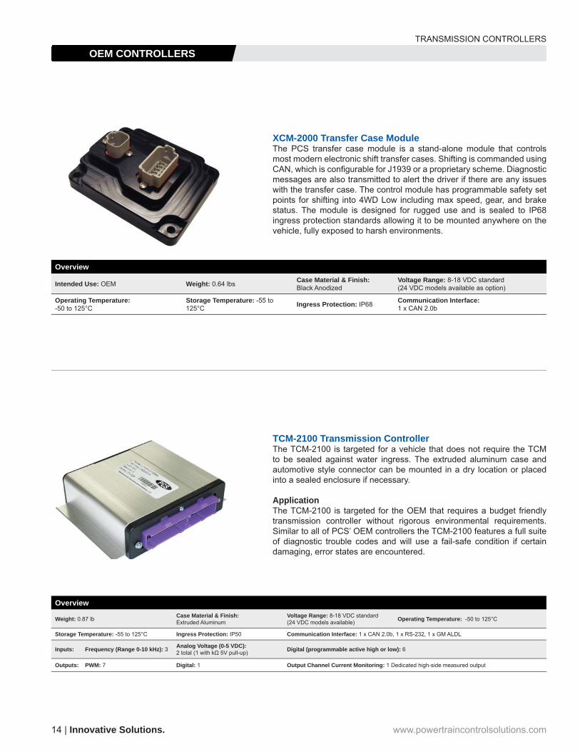
Intended Use: OEM Weight: 0.64 lbs Case Material & Finish: Black Anodized
Voltage Range: 8-18 VDC standard (24 VDC models available as option)
Operating Temperature: -50 to 125°C
Storage Temperature: -55 to 125°C Ingress Protection: IP68 Communication Interface:
1 x CAN 2.0b
TCM-2100 Transmission ControllerThe TCM-2100 is targeted for a vehicle that does not require the TCM to be sealed against water ingress. The extruded aluminum case and automotive style connector can be mounted in a dry location or placed into a sealed enclosure if necessary.
ApplicationThe TCM-2100 is targeted for the OEM that requires a budget friendly transmission controller without rigorous environmental requirements. Similar to all of PCS’ OEM controllers the TCM-2100 features a full suite of diagnostic trouble codes and will use a fail-safe condition if certain damaging, error states are encountered.
XCM-2000 Transfer Case ModuleThe PCS transfer case module is a stand-alone module that controls most modern electronic shift transfer cases. Shifting is commanded using CAN, which is confi gurable for J1939 or a proprietary scheme. Diagnostic messages are also transmitted to alert the driver if there are any issues with the transfer case. The control module has programmable safety set points for shifting into 4WD Low including max speed, gear, and brake status. The module is designed for rugged use and is sealed to IP68 ingress protection standards allowing it to be mounted anywhere on the vehicle, fully exposed to harsh environments.
Overview
Weight: 0.87 lb Case Material & Finish: Extruded Aluminum
Voltage Range: 8-18 VDC standard(24 VDC models available) Operating Temperature: -50 to 125°C
Storage Temperature: -55 to 125°C Ingress Protection: IP50 Communication Interface: 1 x CAN 2.0b, 1 x RS-232, 1 x GM ALDL
Inputs: Frequency (Range 0-10 kHz): 3 Analog Voltage (0-5 VDC): 2 total (1 with kΩ 5V pull-up) Digital (programmable active high or low): 6
Outputs: PWM: 7 Digital: 1 Output Channel Current Monitoring: 1 Dedicated high-side measured output
TRANSMISSION CONTROLLERS
OEM CONTROLLERS
Intuitive Designs. | 15+1 (804) 227-3023
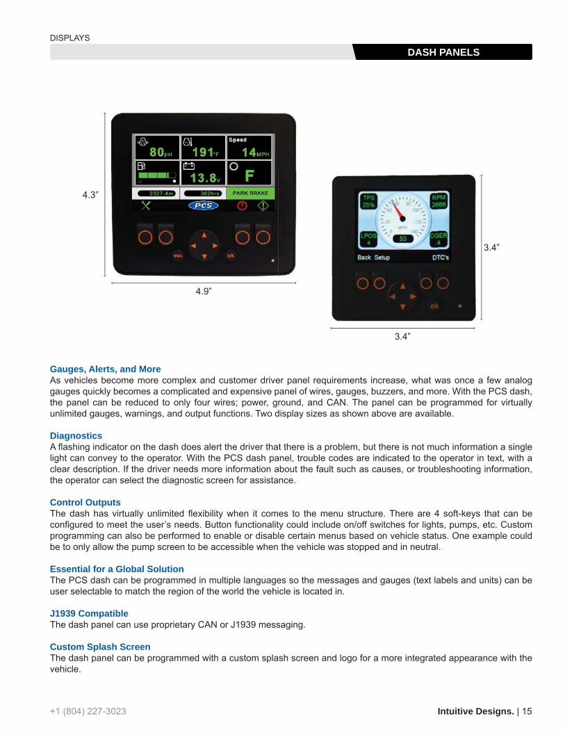
Gauges, Alerts, and MoreAs vehicles become more complex and customer driver panel requirements increase, what was once a few analog gauges quickly becomes a complicated and expensive panel of wires, gauges, buzzers, and more. With the PCS dash, the panel can be reduced to only four wires; power, ground, and CAN. The panel can be programmed for virtually unlimited gauges, warnings, and output functions. Two display sizes as shown above are available.
DiagnosticsA fl ashing indicator on the dash does alert the driver that there is a problem, but there is not much information a single light can convey to the operator. With the PCS dash panel, trouble codes are indicated to the operator in text, with a clear description. If the driver needs more information about the fault such as causes, or troubleshooting information, the operator can select the diagnostic screen for assistance.
Control OutputsThe dash has virtually unlimited fl exibility when it comes to the menu structure. There are 4 soft-keys that can be confi gured to meet the user’s needs. Button functionality could include on/off switches for lights, pumps, etc. Custom programming can also be performed to enable or disable certain menus based on vehicle status. One example could be to only allow the pump screen to be accessible when the vehicle was stopped and in neutral.
Essential for a Global SolutionThe PCS dash can be programmed in multiple languages so the messages and gauges (text labels and units) can be user selectable to match the region of the world the vehicle is located in.
J1939 CompatibleThe dash panel can use proprietary CAN or J1939 messaging.
Custom Splash ScreenThe dash panel can be programmed with a custom splash screen and logo for a more integrated appearance with the vehicle.
4.3”
4.9”
3.4”
3.4”
DISPLAYS
DASH PANELS

16 | Innovative Solutions. www.powertraincontrolsolutions.com
Gear IndicatorThe PCS gear indicator scans a vehicle’s CAN bus and displays current gear data allowing technicians and vehicle operators to monitor the actual current gear used by the transmission, not just the lever position.
The data is displayed on a 5x8 LED dot-matrix display housed in a rugged plastic enclosure. The module automatically enters a low-power standby mode when no activity is detected on the vehicle’s CAN bus ensuring low battery drain when the vehicle is not in use. There are three available harness options including unterminated, OBDII, or PCS option connector.
CAN Formats• PCS TCU “Current Gear” @ 500kbps• PCS D200 Dashlogger “CGER” @ 500kbps• GMLAN “Commanded Gear” @ 500kbps• J1939 “Current Gear” @ 250kbps
Features• Auto scans to determine CAN standard used on vehicle (No user setup is required) • Red LED 5x8 matrix used to display characters P, N, R, 1, 2, 3, 4, 5, 6, 7, 8• Display brightness automatically adjusts to match ambient light levels• Rated for 8-36V nominal battery voltage• Power, Ground, CANH and CANL are the only necessary connections
Description Unterminated OBDII PCS Option ConnectorPCS Gear Indicator, Red Display GDS-5010 GDS-5011 GDS-5012
PCS Gear Indicator, Blue Display GDS-5020 GDS-5021 GDS-5022
PCS Gear Indicator, Green Display GDS-5030 GDS-5031 GDS-5032
PCS Gear Indicator, Yellow Display GDS-5040 GDS-5041 GDS-5042
Billet Aluminum Gear Display Our billet aluminum gear display uses a digital 16-segment alphanumeric display to show P, R, N, D, and gear positions 1 through 9. It comes in two sizes for ease of integration into your hot rods dash and is available in either polished or black anodized fi nishes. This display also has automatic night-time dimming and easily connects to any of our transmission controllers via CAN.
Description Part #Gear Display Black 2” OD, 1.2” Display TCM-3700
Gear Display Polished 2” OD, 1.2” Display TCM-3701
Gear Display Black 1.75” OD, 0.8” Display TCM-3702
Gear Display Polished 1.75” OD, 0.8” Display TCM-3703
*Actual Size
TCM-3700TCM-3703
DISPLAYS
GEAR INDICATORS

Intuitive Designs. | 17+1 (804) 227-3023
D200 DashloggerThe D200 Dash Logger is a high contrast, 6-inch viewable, transfl ective touchscreen that is easily seen in day or night. The durable, high sensitivity, resistive touchscreen can be easily activated with a stylus or fi nger.
Inputs and OutputsThe D200 has 8 analog inputs, 2 speed inputs, and 2 PWM outputs. The analog inputs can be used for engine sensors, a data log start switch, or any other voltage you wish to monitor and log. All D200 inputs can also be labeled by the user for a customized display. The versatile PWM outputs can perform a variety of tasks from an external shift light to boost control. The D200 communicates with external devices using RS-232 or CAN 2.0b. RS-232 is typically used for communicating with serial ECU’s. CAN is used to communicate with all other PCS devices keeping wiring harness requirements to a bare minimum.
Monitor ScreensThe D200 offers several fully programmable monitor screens capable of displaying any combination of inputs. This allows the user to select the most appropriate view for the situation, such as a large tachometer for the track, or a screen with over 20 items for diagnosing a problem. Confi guration of individual gauges is as simple as touching the gauge on the screen and selecting the input you wish to associate with it. The D200 also allows the user to select the scale and units for the displayed data. Programmable alarms allow the user to set high and low points for a particular input. If the input exceeds the specifi cations, the D200 will alert the driver by fl ashing the gauge or item. Shift light functionality can be accomplished by having the D200 fl ash the screen at a desired RPM.
Data Logging & PlaybackThe D200 is the heart of the PCS logging system. When combined with PCS data logging software, the user is able to analyze all the information. The D200 is equipped with 2MB of on-board data log memory. Additional memory (up to 16MB) is available at the time of purchase. To optimize the memory usage, the user can select different logging rates for each device from 5HZ up to 1000HZ. The start of the log is triggered with the touchscreen or a button wired to an input. Multiple logs can be stored on the unit. Logs are stored by date and time and are also viewable through a data log explorer on the D200 screen itself so any run can be played back on the D200 to gather information about the run without needing a laptop. The laptop communicates using USB, making quick work of downloading large data logs.
OEM DiagnosticsPCS offers several tools for OEM in-fi eld support. These tools enable the technician to read and clear trouble codes, view sensor data, and capture a data log. The data logs can be reviewed on-site using the PC software or sent back to PCS or the vehicle manufacturer for further analysis. These tools do not allow access to the calibration on the transmission controller to ensure the factory calibration is not modifi ed, potentially compromising the life of the transmission.
Available products include Windows based PC software, a 6-inch touchscreen LCD, and a 3-inch color LCD screen. Communication is established using RS-232, GM ALDL, or CAN.
These tools are also well suited for an end-of-line test on the vehicle assembly line to check for trouble codes and verify vital transmission inputs including throttle position, vehicle speed, and engine RPM.
DISPLAYS
DATA LOGGING & DIAGNOSTICS

The GSM Push Button Shifter is an electronically controlled shifter that replaces the shift lever and offers precise, split-second shifting capability with the push of a button. The GSM was designed and is well suited for a variety of markets including automotive, military and agricultural and works with nearly any automatic transmission.
Its slim touch pad control module and compact, sealed actuator give you virtually unlimited mounting options for tight spaces and grueling environments. The GSM control module can be surface or fl ush-mounted and is small enough to fi t consoles, dashes, door panels or even armrests. An easy to read display shows the vehicle’s current gear and each button is recessed to avoid inadvertent touches and brightly backlit for all environments.
The GSM monitors vehicle speed and brake switch status to ensure the vehicle is slowed to a safe speed and the brake is pressed to prevent inadvertent shift in or out of Park, or into Reverse while moving forward. The GSM has built-in contacts for neutral safety for simple wiring to the start circuit and reverse lights can be controlled from the GSM’s reverse circuit contacts.
Installation kits are available for most common transmissions and should be ordered with your GSM. An electronic vehicle speed signal is required and mechanical to electric speed signal generators are available for GM and Ford cable driven speedometers.
Gear Select Module KitDescription Part #
Gear Select Module kit including cable drive and driver interface panel GSM-5000
Vehicle Speed InterfacesDescription Part #GM Speed Signal Generator GSM-2050
Ford Speed Signal Generator GSM-2060
GSM GM Speed Sensor Pass-Through Adapter GSM-2080
GM Bulkhead Pass-Through w/ CAN and Option Connector Breakouts WRE-3500
Install KitsDescription Part #GSM Install Kit for GM 4L60/65/70/80/85 w/ PRNDL GSM-2010
GSM Install Kit for Ford AODE/4R70W GSM-2011
GSM Install Kit for GM TH-200/200-4R/250/350/400/700-R4, 4L60/65/60/85 w/out PRNDL GSM-2012
GSM Install Kit for Ford 1965-1982 C-4 GSM-2013
GSM Install Kit for GM 1962-1973 Powerglide GSM-2014
GSM Install Kit for Ford AOD GSM-2015
GSM Install Kit for Chrysler 1966+ 727 or 904 Torquefl ite and AMC 1972+ Torque Command Transmission GSM-2016
18 | Innovative Solutions. www.powertraincontrolsolutions.com
SHIFTERS
GEAR SELECT MODULE
+1 (804) 227-3023 Intuitive Designs. | 19
Description Part #Paddle Shifter w/ display for 5 or 6 bolt wheel PS-2001
Paddle Shifter w/out display for 5 or 6 bolt wheel PS-2000
Paddle Shifter w/ display for 9 bolt wheel PS-2006
Paddle Shifter w/out display for 9 bolt wheel PS-2005
Paddle Shifter w/ display for 5 or 6 bolt wheel for GM Mechatronic transmission PS-2011
Paddle Shifter w/out display for 5 or 6 bolt wheel for GM Mechatronic transmission PS-2010
Paddle Shifter w/ display for 9 bolt wheel for GM Mechatronic transmission PS-2016
Paddle Shifter w/out display for 9 bolt wheel for GM Mechatronic transmission PS-2015
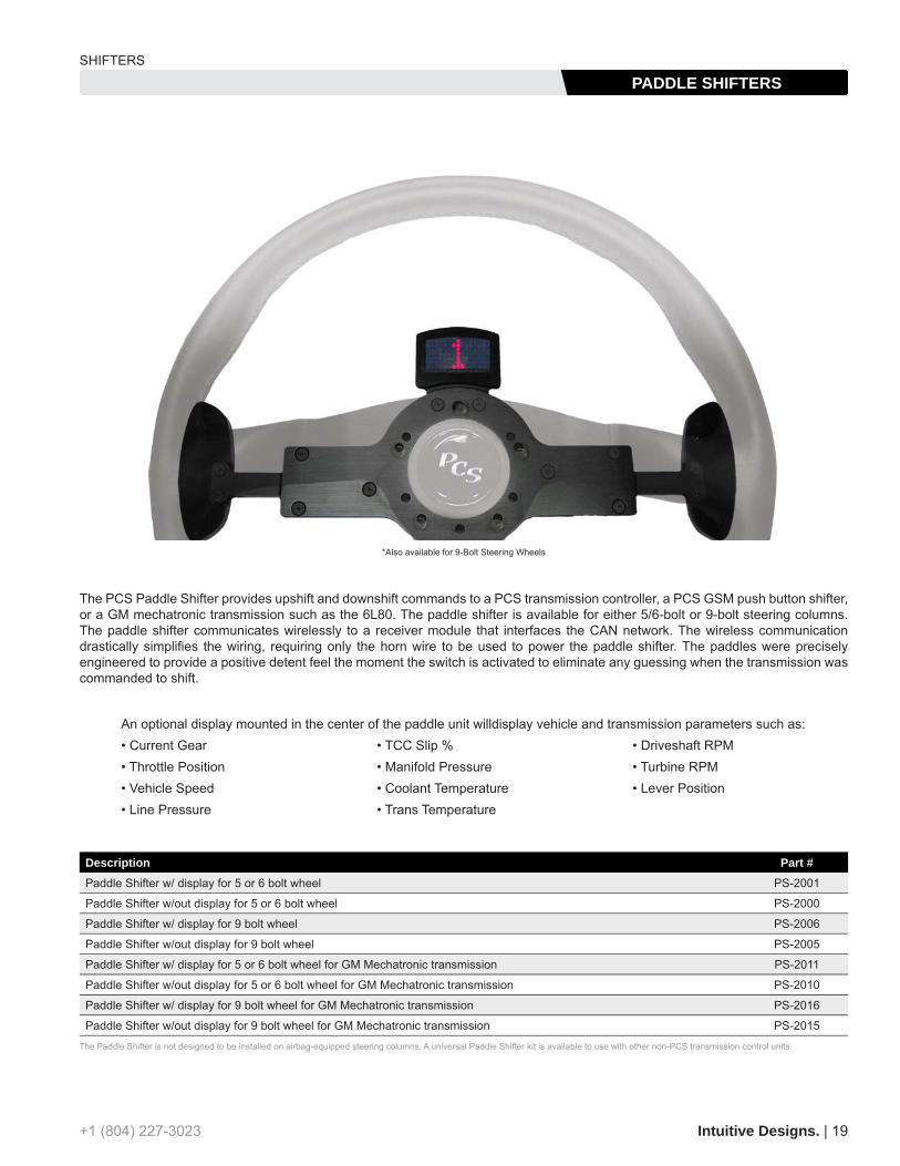
The PCS Paddle Shifter provides upshift and downshift commands to a PCS transmission controller, a PCS GSM push button shifter, or a GM mechatronic transmission such as the 6L80. The paddle shifter is available for either 5/6-bolt or 9-bolt steering columns. The paddle shifter communicates wirelessly to a receiver module that interfaces the CAN network. The wireless communication drastically simplifi es the wiring, requiring only the horn wire to be used to power the paddle shifter. The paddles were precisely engineered to provide a positive detent feel the moment the switch is activated to eliminate any guessing when the transmission was commanded to shift.
The Paddle Shifter is not designed to be installed on airbag-equipped steering columns. A universal Paddle Shifter kit is available to use with other non-PCS transmission control units.
*Also available for 9-Bolt Steering Wheels
An optional display mounted in the center of the paddle unit willdisplay vehicle and transmission parameters such as:• Current Gear • TCC Slip % • Driveshaft RPM• Throttle Position • Manifold Pressure • Turbine RPM• Vehicle Speed • Coolant Temperature • Lever Position• Line Pressure • Trans Temperature
SHIFTERS
PADDLE SHIFTERS

20 | Innovative Solutions. www.powertraincontrolsolutions.com
DATA ACQUISITION
CAN MODULES
Three-Axis Accelerometer and Gyro ModuleThe PCS 3-Axis Accelerometer and Gyro allows monitoring of linear and angular acceleration rates for determining tire and suspension setup, track conditions, and general vehicle dynamics. The Accelerometer outputs all three axes via CAN bus where it can be displayed and logged. The axis resolution is programmable so the module can be optimized for the particular application.
Description Part #3-Axis Accelerometer & Gyro ACC-3000
Dual Channel CAN-USB Interface CableThe PCS CAN-USB cable is a dual channel CAN interface. Compatible with CAN 2.0A and CAN 2.0B, this USB interface allows for monitoring, transmitting, and bridging CAN networks. Windows software is included to confi gure speeds and operation and also allows data logging and message fi ltering. The interface can be used as a single channel device interfacing one CAN network, or can independently monitor andbridge two different CAN networks running at different speeds.
Description Part #Dual Channel CAN-USB Interface Cable CAN-5000
EGT-5100
Exhaust Gas Temperature ModuleExhaust Gas Temperature, or EGT, is a fundamental tool in tuning, diagnosing problems, and ensuring the proper operating range of an internal combustion engine. This simple, but effective tool can diagnose potential engine problems before failure and ensure proper cylinder equalization when tuning or running an engine at the edge of its operating capabilities.
Description Part #EGT-2000 8-Channel EGT Module Kit Including Harness EGT-5100
Single Channel EGT Module, converts temperature to 0-5 volt analog voltage EGT-5000
ThermocouplesDescription Part #Thermocouple 1/4” tube 12” with Mini Connector EGT-4025
Thermocouple 1/4” tube 24” with Mini Connector EGT4027
Thermocouple 1/4” tube 36” with Mini Connector EGT-4028
Thermocouple 1/4” tube 48” with Mini Connector EGT-4024
Thermocouple 1/4” tube 60” with Mini Connector EGT-4029
EGT-4025EGT 4025
ACC-3000
CAN-5000
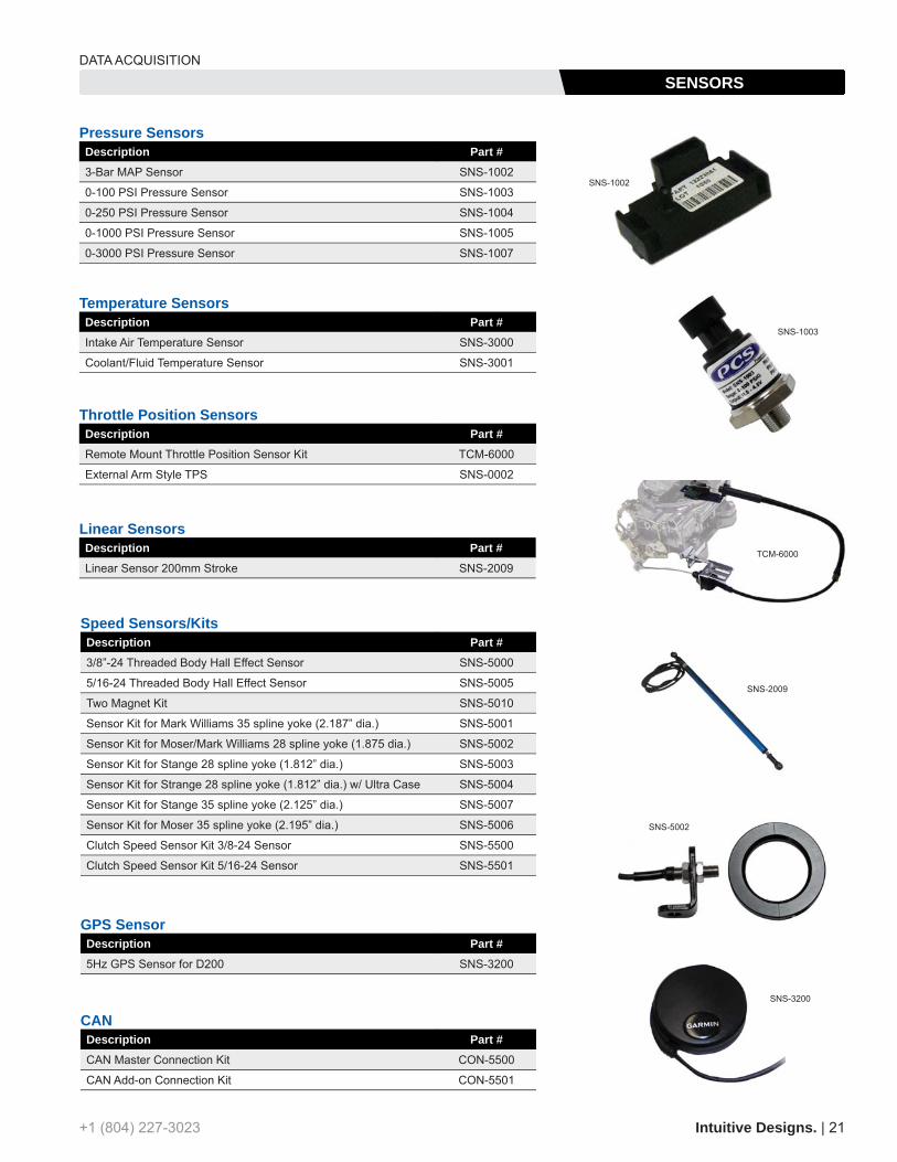
GPS SensorDescription Part #5Hz GPS Sensor for D200 SNS-3200
CANDescription Part #CAN Master Connection Kit CON-5500
CAN Add-on Connection Kit CON-5501
Throttle Position SensorsDescription Part #Remote Mount Throttle Position Sensor Kit TCM-6000
External Arm Style TPS SNS-0002
Linear SensorsDescription Part #Linear Sensor 200mm Stroke SNS-2009
Temperature SensorsDescription Part #Intake Air Temperature Sensor SNS-3000
Coolant/Fluid Temperature Sensor SNS-3001
Speed Sensors/KitsDescription Part #3/8”-24 Threaded Body Hall Effect Sensor SNS-5000
5/16-24 Threaded Body Hall Effect Sensor SNS-5005
Two Magnet Kit SNS-5010
Sensor Kit for Mark Williams 35 spline yoke (2.187” dia.) SNS-5001
Sensor Kit for Moser/Mark Williams 28 spline yoke (1.875 dia.) SNS-5002
Sensor Kit for Stange 28 spline yoke (1.812” dia.) SNS-5003
Sensor Kit for Strange 28 spline yoke (1.812” dia.) w/ Ultra Case SNS-5004
Sensor Kit for Stange 35 spline yoke (2.125” dia.) SNS-5007
Sensor Kit for Moser 35 spline yoke (2.195” dia.) SNS-5006
Clutch Speed Sensor Kit 3/8-24 Sensor SNS-5500
Clutch Speed Sensor Kit 5/16-24 Sensor SNS-5501
Pressure SensorsDescription Part #3-Bar MAP Sensor SNS-1002
0-100 PSI Pressure Sensor SNS-1003
0-250 PSI Pressure Sensor SNS-1004
0-1000 PSI Pressure Sensor SNS-1005
0-3000 PSI Pressure Sensor SNS-1007
TCM-6000
SNS-3200
SNS-2009
SNS-1003
SNS-1002
SNS-5002
Intuitive Designs. | 21+1 (804) 227-3023
DATA ACQUISITION
SENSORS

Driveline Integration & ValidationPCS provides complete driveline integration services for vehicle manufacturers. PCS can assist during the entire development cycle including component design, selection, validation, production procurement, and fi nal assembly. PCS services include, but are not limited to the items below.
Transmission Simulation and SelectionComputer simulation of vehicle and transmission performance based vehicle specifi c parameters including GVW, engine, and fi nal drive ratio. Several transmission options will be evaluated and compared. Factors also considered are cost, availability (new or remanufactured), suitability for vehicle mission, and other implementation factors. For four-wheel-drive applications, the transfer case can be included in the analysis.
Engine to Transmission InterfaceCAD design and analysis includes alignment, torque converter engagement, production feasibility, and costs. Custom bell housings can be designed to simplify installation and reduce production costs. PCS offers bell housings for popular engine/transmission combinations including SAE4 and SAE3 to GM 4L60/70.
Vehicle FitmentCAD design and analysis of vehicle specifi c transmission mount loading capability, transmission fi eld serviceability, driveline angle, transmission angle, maximum vehicle operation angle, driveshaft and axles, shift mechanism, cooling system, neutral safety, reverse indication, and parking brake.
Calibration, Validation, and Durability TestingTransmission calibration and validation is offered to insure the transmission is properly integrated into the vehicle. While continuously monitoring transmission load, slip, cooling, and other variables, durability testing can be performed to verify the transmission will withstand the mission for the expected life of the vehicle.
SAE4 GM 4L60/70 Bellhousing
GM 4L60/70 4WD w/ transfer case and custom PCS bellhousing
22 | Innovative Solutions. www.powertraincontrolsolutions.com
CAPABILITIES
ENGINEERING
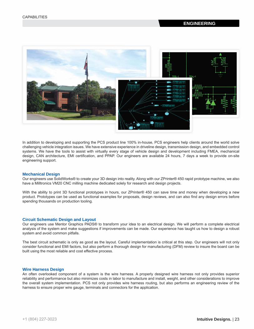
In addition to developing and supporting the PCS product line 100% in-house, PCS engineers help clients around the world solve challenging vehicle integration issues. We have extensive experience in driveline design, transmission design, and embedded control systems. We have the tools to assist with virtually every stage of vehicle design and development including FMEA, mechanical design, CAN architecture, EMI certifi cation, and PPAP. Our engineers are available 24 hours, 7 days a week to provide on-site engineering support.
Mechanical DesignOur engineers use SolidWorks® to create your 3D design into reality. Along with our ZPrinter® 450 rapid prototype machine, we also have a Milltronics VM20 CNC milling machine dedicated solely for research and design projects.
With the ability to print 3D functional prototypes in hours, our ZPrinter® 450 can save time and money when developing a new product. Prototypes can be used as functional examples for proposals, design reviews, and can also fi nd any design errors before spending thousands on production tooling.
Circuit Schematic Design and LayoutOur engineers use Mentor Graphics PADS® to transform your idea to an electrical design. We will perform a complete electrical analysis of the system and make suggestions if improvements can be made. Our experience has taught us how to design a robust system and avoid common pitfalls.
The best circuit schematic is only as good as the layout. Careful implementation is critical at this step. Our engineers will not only consider functional and EMI factors, but also perform a thorough design for manufacturing (DFM) review to insure the board can be built using the most reliable and cost effective process.
Wire Harness DesignAn often overlooked component of a system is the wire harness. A properly designed wire harness not only provides superior reliability and performance but also minimizes costs in labor to manufacture and install, weight, and other considerations to improve the overall system implementation. PCS not only provides wire harness routing, but also performs an engineering review of the harness to ensure proper wire gauge, terminals and connectors for the application.
Intuitive Designs. | 23+1 (804) 227-3023
CAPABILITIES
ENGINEERING

24 | Innovative Solutions. www.powertraincontrolsolutions.com
PCS’s manufacturing division, Wintronics, manufactures all of PCS’s products and also provides contract manufacturing to other clients.
Wintronics offers a complete partnership experience beyond the typical contract manufacturing relationship. Services including initial design assistance, design reviews for ease of manufacturing, and rapid prototype capability can transform a product from an idea to full production quickly and effi ciently. Wintronics has experience in high volume, military qualifi ed products and understands all the requirements those products must undergo to satisfy the most stringent specifi cations. Their continually trained and experienced staff, in combination with the scope of their assembly equipment, results in an extensive capability to provide a full range of through hole to mixed technology to fi ne pitch, double-sided, SMT PCB assembly. They can provide a critical design review before time and money are spent at the lab. Also, Wintronics can design custom end-of-line test equipment to ensure your product is 100% tested and burned-in before it is shipped to your customer.
About WintronicsWintronics is a full service, ISO 9001 certifi ed, electronic and electromechanical contract manufacturer supporting customers in both commercial and industrial markets. The Wintronics’ goal is to earn the customer’s respect as an extension of their process, their performance standards, their company. Located in Sharon, PA, Wintronics occupies an ESD compliant facility, strategically located just a few miles off Interstate 80 and within an hour’s drive of Pittsburgh, Cleveland, or Youngstown, OH airports.
• Order Fulfi llment• Wire Harness Manufacturing• Design for Manufacturing (DFM) • Design for Test (DFT) • Concurrent Engineering (CE) • Turnkey Material Management • MRP II/JIT • Box Build • Quality Assurance Program Compliance
Products and Services• Engineering Evaluation and Consultation • PCB Design, Layout, and Documentation • Design for Manufacturability and for test • Material Management: Consignment and Turnkey • PCBA Manufacturing • Compliance to ANSI/IPC-A-610 Class II, III • ISO 9001 Quality System • Functional PCBA and box assembly test • Electromechanical, ‘Box Build’ • Box Assembly burn-in
CAPABILITIES
MANUFACTURING

Intuitive Designs. | 25+1 (804) 227-3023
GM Platinum Supplier StatusIn recognition of delivering quality product 100% on time for twelve months, General Motors awarded PCS with “Platinum Supplier Status.” This award not only refl ects the effort and commitment, we at PCS strive for, but our ability to deliver a quality product in a timely manner.
About UsPowertrain Control Solutions, LLC. was founded in 2003 to design and manufacture electronic control systems for automotive pow-ertrain applications. Our knowledgeable staff combines over 50 years of electronic design and manufacturing experience. Since our inception, our product line has grown to include complete vehicle data acquisition systems, automatic transmission controllers, and automatic transmission packages.
In the Spring of 2012, PCS opened a new headquarters and engineering center. The new facility provides extensive engineering space and features a large, temperature controlled shop for research and development. The new building also has a large training room for dealer education and transmission information workshops.
We believe that long term growth and profi tability comes from a strong foundation of reliable, well supported products rather than marketing fl ash. We focus on engineering the highest quality products at the lowest possible cost. Our unique approach combines hard work and years of experience to deliver excellent products. At PCS, we test every electronic part we manufacture rigorously and we’ll proudly stand behind all of our products.
Powertrain Control Solutions, LLC.10511 Old Ridge Rd. Ashland, VA 23005Ph: +1 (804) 227-3023 Fax: 1.804.227.3005Sales: [email protected] Tech Support: [email protected]
ABOUT PCS
Powertrain Control Solutions, LLC10511 Old Ridge Rd. Ashland, VA 23005 Catalog OEM 0915
LIMITED WARRANTY STATEMENT. Powertrain Control Solutions, LLC. Warrants all merchandise against defects in factory workmanship and materials for a period of 12 months after purchase. This warranty applies to the fi rst retail purchaser and covers only those products exposed to normal use or service. Provisions of this warranty shall not apply to a Powertrain Control Solutions, LLC. Product used for a purpose for which it is not designed, or which has been altered in any way that would be detrimental to the performance or life of the product, or misapplication, misuse, negligence or accident. On any part or product found to be defective after examination by Powertrain Control Solutions, LLC., Powertrain Control Solutions, LLC. will only repair or replace the merchandise through the original selling dealer or aon a direct basis. Powertrain Control Solutions, LLC. assumes no responsibility for diagnosis, removal and/or installation labor, loss of vehicle use, loss of time, inconvenience or any other consequential expenses. The warranties herein are in lieu of any other expressed or implied warranties, including any implied warranty of merchantability or fi tness, and any other obligation on the part of Powertrain Control Solutions, LLC., or selling dealer.