pco.labview - hep group research pages · this document describes the commands for controlling the...
TRANSCRIPT

pc
o.la
bvie
w
pco. document
pco.camera / LabVIEW Interface Description
File: MA_DCLABVIEWver104.doc
Version: 1.04
as of: 16.11.2005
Author: MM/FRE/ LWA/ EO/ GHO
Page 1 of 1
pco.labview
LLaabbVVIIEEWW ddrriivveerr ffoorr ppccoo..ccaammeerraa This document describes the LabVIEW interface to the pco.camera series.

pc
o.la
bvie
w
pco. document
pco.camera / LabVIEW Interface Description
File: MA_DCLABVIEWver104.doc
Version: 1.04
as of: 16.11.2005
Author: MM/FRE/ LWA/ EO/ GHO
Page 2 of 2
Copyright © 2005 pco AG (called pco in the following text), Kelheim, Germany. All rights reserved. pco assumes no responsibility for errors or omissions in these materials. These materials are provided "as is" without warranty of any kind, either expressed or implied, including but not limited to, the implied warranties of merchantability, fitness for a particular purpose, or non-infringement. pco further does not warrant the accuracy or completeness of the information, text, graphics, links or other items contained within these materials. pco shall not be liable for any special, indirect, incidental, or consequential damages, including without limitation, lost revenues or lost profits, which may result from the use of these materials. The information is subject to change without notice and does not represent a commitment on the part of pco in the future. pco hereby authorizes you to copy documents for non-commercial use within your organization only. In consideration of this authorization, you agree that any copy of these documents that you make shall retain all copyright and other proprietary notices contained herein. Each individual document published by pco may contain other proprietary notices and copyright information relating to that individual document. Nothing contained herein shall be construed as conferring by implication or otherwise any license or right under any patent or trademark of pco or any third party. Except as expressly provided above nothing contained herein shall be construed as conferring any license or right under any pco copyright. Note that any product, process, or technology in this document may be the subject of other intellectual property rights reserved by pco, and may not be licensed hereunder.

pc
o.la
bvie
w
pco. document
pco.camera / LabVIEW Interface Description
File: MA_DCLABVIEWver104.doc
Version: 1.04
as of: 16.11.2005
Author: MM/FRE/ LWA/ EO/ GHO
Page 3 of 3
(Table of Content ... continued)
A. COMMAND STRUCTURE...........................................................................7
1 GENERAL................................................................................................................................7
1.1 Conventions ......................................................................................................................................... 7
1.2 Hardware elements, interface connectors......................................................................................... 8
2 OVERVIEW AND FUNCTION DESCRIPTION ........................................................................9
2.1 GeneralControlStatus.llb – Camera control .................................................................................... 9
2.2 Sensor.llb - Image sensor specifics .................................................................................................. 10
2.3 TimingControl.llb – Image timing................................................................................................... 10
2.4 Storage.llb – Camera memory management .................................................................................. 11
2.5 RecordingControl.llb – Image recording controls......................................................................... 13
2.6 Image Read........................................................................................................................................ 15
2.7 APIManagement.llb – Programming interface controls............................................................... 15
B. IMPLEMENTATION DETAILS..............................................................16
3 COMMUNICATION LAYERS.................................................................................................16
4 SAMPLE APPLICATION .......................................................................................................17
5 INTERFACE LIBRARY SECTIONS.......................................................................................26
5.1 GeneralControlStatus.llb ................................................................................................................. 26 5.1.1 ErrorManager.vi.......................................................................................................................... 26 5.1.2 FormatHWDESC.vi .................................................................................................................... 28
Table of Contents:

pc
o.la
bvie
w
pco. document
pco.camera / LabVIEW Interface Description
File: MA_DCLABVIEWver104.doc
Version: 1.04
as of: 16.11.2005
Author: MM/FRE/ LWA/ EO/ GHO
Page 4 of 4
5.1.3 FormatSoftwareDesc.vi .............................................................................................................. 28 5.1.4 GetCameraHealthStatus.vi.......................................................................................................... 29 5.1.5 GetCameraType.vi ...................................................................................................................... 32 5.1.6 GetGeneral.vi .............................................................................................................................. 35 5.1.7 GetTemperatures.vi..................................................................................................................... 40 5.1.8 InitiateSelfTestProcedure.vi........................................................................................................ 42 5.1.9 ResetSettingsToDefault.vi .......................................................................................................... 45 5.1.10 StripCamType.vi......................................................................................................................... 47
5.2 Sensor.llb............................................................................................................................................ 48 5.2.1 GetADCOperation.vi .................................................................................................................. 48 5.2.2 GetBinning.vi.............................................................................................................................. 50 5.2.3 GetConversionFactor.vi .............................................................................................................. 52 5.2.4 GetCoolingSetpointTemperature.vi ............................................................................................ 54 5.2.5 GetDescription.vi ........................................................................................................................ 56 5.2.6 GetDoubleImageMode.vi............................................................................................................ 62 5.2.7 GetIRSensitivity.vi...................................................................................................................... 64 5.2.8 GetOffsetMode.vi ....................................................................................................................... 66 5.2.9 GetPixelRate.vi ........................................................................................................................... 68 5.2.10 GetROI.vi.................................................................................................................................... 70 5.2.11 GetSensorFormat.vi .................................................................................................................... 72 5.2.12 GetSizes.vi .................................................................................................................................. 74 5.2.13 SetADCOperation.vi................................................................................................................... 76 5.2.14 SetBinning.vi .............................................................................................................................. 78 5.2.15 SetConversionFactor.vi............................................................................................................... 80 5.2.16 SetCoolingSetpointTemperature.vi............................................................................................. 82 5.2.17 SetDoubleImageMode.vi ............................................................................................................ 84 5.2.18 SetIRSensitivity.vi ...................................................................................................................... 86 5.2.19 SetOffsetMode.vi ........................................................................................................................ 88 5.2.20 SetPixelRate.vi............................................................................................................................ 90 5.2.21 SetROI.vi .................................................................................................................................... 92 5.2.22 SetSensorFormat.vi..................................................................................................................... 94 5.2.23 GetNoiseFilterMode.vi ............................................................................................................... 96 5.2.24 SetNoiseFilterMode.vi ................................................................................................................ 98
5.3 TimingControl.llb ........................................................................................................................... 100 5.3.1 ForceTrigger.vi ......................................................................................................................... 100 5.3.2 GetBusyStatus.vi....................................................................................................................... 102 5.3.3 GetCOCRunTime.vi ................................................................................................................. 104 5.3.4 GetDelayExposureTime.vi........................................................................................................ 106 5.3.5 GetDelayExposureTimeTable.vi .............................................................................................. 108 5.3.6 GetExpTrigSignalStatus.vi ....................................................................................................... 111 5.3.7 GetFPSExposureMode.vi ......................................................................................................... 113 5.3.8 GetPowerDownMode.vi ........................................................................................................... 115 5.3.9 GetTrigger.vi............................................................................................................................. 117

pc
o.la
bvie
w
pco. document
pco.camera / LabVIEW Interface Description
File: MA_DCLABVIEWver104.doc
Version: 1.04
as of: 16.11.2005
Author: MM/FRE/ LWA/ EO/ GHO
Page 5 of 5
5.3.10 GetUserPowerDownTime.vi..................................................................................................... 120 5.3.11 SetDelayExposureTime.vi ........................................................................................................ 122 5.3.12 SetDelayExposureTimeTable.vi ............................................................................................... 124 5.3.13 SetFPSExposureMode.vi .......................................................................................................... 127 5.3.14 SetPowerDownMode.vi ............................................................................................................ 129 5.3.15 SetTrigger.vi ............................................................................................................................. 131 5.3.16 SetUserPowerDownTime.vi ..................................................................................................... 134
5.4 Storage.llb ........................................................................................................................................ 136 5.4.1 ClearRAMSegment.vi............................................................................................................... 136 5.4.2 GetActiveRAMSegment.vi....................................................................................................... 138 5.4.3 GetCameraRAMSize.vi ............................................................................................................ 140 5.4.4 GetCamRAMSegmentSize.vi ................................................................................................... 142 5.4.5 SetActiveRAMSegment.vi........................................................................................................ 144 5.4.6 SetCamRAMSegmentSize.vi.................................................................................................... 146
5.5 RecordingControl.llb ...................................................................................................................... 148 5.5.1 ArmCamera.vi........................................................................................................................... 148 5.5.2 GetAcquireEnableSignalStatus.vi............................................................................................. 150 5.5.3 GetAcquireMode.vi .................................................................................................................. 152 5.5.4 GetRecorderSubmode.vi........................................................................................................... 154 5.5.5 GetRecordingState.vi ................................................................................................................ 156 5.5.6 GetStorageMode.vi ................................................................................................................... 158 5.5.7 GetTimeStampMode.vi............................................................................................................. 160 5.5.8 SetAcquireMode.vi ................................................................................................................... 162 5.5.9 SetDateTime.vi ......................................................................................................................... 164 5.5.10 SetRecorderSubmode.vi............................................................................................................ 166 5.5.11 SetRecordingState.vi................................................................................................................. 168 5.5.12 SetStorageMode.vi.................................................................................................................... 170 5.5.13 SetTimeStampMode.vi ............................................................................................................. 172
5.6 BufferData.llb.................................................................................................................................. 174 5.6.1 GetBitAlignment.vi................................................................................................................... 174 5.6.2 GetImageSegmentSettings.vi.................................................................................................... 176 5.6.3 GetNumberOfImagesInSegment.vi .......................................................................................... 179 5.6.4 SetBitAlignment.vi ................................................................................................................... 181
5.7 APIManagement.llb........................................................................................................................ 184 5.7.1 AddBuffer.vi (***Obsolete – Use AddBufferEx.vi for new development) ............................. 184 5.7.2 AddBufferEX.vi........................................................................................................................ 186 5.7.3 AllocateBuffer.vi ...................................................................................................................... 189 5.7.4 CancelImages.vi........................................................................................................................ 192 5.7.5 CheckDeviceAvailability.vi...................................................................................................... 194 5.7.6 CloseCamera.vi......................................................................................................................... 196 5.7.7 FreeBuffer.vi............................................................................................................................. 198

pc
o.la
bvie
w
pco. document
pco.camera / LabVIEW Interface Description
File: MA_DCLABVIEWver104.doc
Version: 1.04
as of: 16.11.2005
Author: MM/FRE/ LWA/ EO/ GHO
Page 6 of 6
5.7.8 GetBufferStatus.vi .................................................................................................................... 200 5.7.9 GetImage.vi (***Obsolete – Use GetImageEx.vi for new development***) .......................... 202 5.7.10 GetImageEX.vi ......................................................................................................................... 205 5.7.11 GetImageBuffer.vi .................................................................................................................... 208 5.7.12 GetPendingBuffer.vi ................................................................................................................. 210 5.7.13 OpenCamera.vi (***Obsolete – Use GetImageEx.vi for new development***)..................... 212 5.7.14 OpenCameraEx.vi..................................................................................................................... 214 5.7.15 CamLinkSetImageParameters.vi .............................................................................................. 217 5.7.16 GetTransferParameters.vi ......................................................................................................... 219 5.7.17 SetTransferParameters.vi .......................................................................................................... 222
6 ERROR / WARNING CODES ..............................................................................................225

pc
o.la
bvie
w
pco. document
pco.camera / LabVIEW Interface Description
File: MA_DCLABVIEWver104.doc
Version: 1.04
as of: 16.11.2005
Author: MM/FRE/ LWA/ EO/ GHO
Page 7 of 7
A. Command Structure
This document describes the commands for controlling the pco.camera from within the National Instruments LabVIEW environment. Further explanations appear as needed for the commands, settings and mode configurations.
1 General • Conventions in this manual • Hardware elements and interface connectors
1.1 Conventions
The following typographic conventions are used in this manual: bold: get camera type Functions, procedures or modes used [words in brackets]: [run] Possible values or “states” of the described functions ALL CAPITAL WORDS: TRUE Logical or boolean values such as TRUE, FALSE, ON, OFF, 0, 1, RISING, FALLING, HIGH, LOW <words in arrows>: <acq enbl> Names of hardware input / output signals

pc
o.la
bvie
w
pco. document
pco.camera / LabVIEW Interface Description
File: MA_DCLABVIEWver104.doc
Version: 1.04
as of: 16.11.2005
Author: MM/FRE/ LWA/ EO/ GHO
Page 8 of 8
1.2 Hardware elements, interface connectors
figure 1: View of back panel of pco.power legend: [a] <control in> - general input for external control signals, BNC plugs [b] <exp trig> - external exposure trigger input [c] <acq enbl> - external acquire enable input [d] <status out> - general status output signals, BNC plugs [e] <exp> - exposure output signal [f] <busy> - busy output signal [g] DIP switch, which sets polarity, HIGH and LOW levels and level of voltages [h] [TTL] or [>10V] selects voltage level either TTL = 5V or larger than 10V [i] or trigger edge selection for <exp trig> input, either rising or falling edge [j] or trigger level selection for <acq enbl> input, HIGH or LOW active [k] [TTL] or [>10V] selects voltage level either TTL = 5V or larger than 10V
[a][b]
[c]
[d]
control inexp trig acq enbl
status outexp busy
TTL TTL
>10V >10V
90-260VAC
camera RS232
[e] [f]
[g] [h] [j] [i] [k]

pc
o.la
bvie
w
pco. document
pco.camera / LabVIEW Interface Description
File: MA_DCLABVIEWver104.doc
Version: 1.04
as of: 16.11.2005
Author: MM/FRE/ LWA/ EO/ GHO
Page 9 of 9
2 Overview and function description
The LabVIEW interface consists of the following files:
- VI Libraries: APIManagement.llb, BufferData.llb, GeneralControlStatus.llb, RecordingControl.llb, Sensor.llb, Storage.llb, TimingControl.llb
- Dynamic Link Libraries: pcolabview2.dll, SC2_Cam.lib, SC2_1394.dll
There are libraries of virtual instruments (VI’s) used for camera control and image acquisition, and lower-level dynamic link library files. Most of the VI’s call functions in the dynamic link library SC2_Cam.dll, which should reside in your application directory. The SC2_Cam.dll in turn accesses the SC2_1394.dll, which should be installed during the driver installation. A third DLL, pcolabview2.dll, handles memory management between the LabVIEW environment and the DLL’s. The VI’s are grouped in libraries by function.
• Camera (General) • Image Sensor • Timing • Storage • Recording • Image Read • API-Management
2.1 GeneralControlStatus.llb – Camera control
This library contains general functions to control the camera and to request information about the camera:
• Request camera type, hardware/firmware version, serial number, interface type • Request camera status (warnings, errors etc.) • Reset all settings to default values • Initiate self test procedure • Get camera / power supply temperature

pc
o.la
bvie
w
pco. document
pco.camera / LabVIEW Interface Description
File: MA_DCLABVIEWver104.doc
Version: 1.04
as of: 16.11.2005
Author: MM/FRE/ LWA/ EO/ GHO
Page 10 of 10
2.2 Sensor.llb - Image sensor specifics
This group contains complete image sensor control instructions and instructions to request information about the sensor. These are:
• Get Camera description: sensor type, standard resolution, extended resolution, dynamic resolution (bit), delay and exposure times…
• Set/request sensor format: [standard] / [extended]. • Set/request ROI settings. • Set/request binning settings. • Set/request pixel rate (frequency for shifting the pixels out of the sensor shift registers). • Set/request conversion factor (gain) settings. • Set/request double image mode (expose two images one after another immediately). • Set/request ADC mode (use one or two ADCs for digitizing the pixel data of the sensor). • Set/request IR sensitivity setting (ON/OFF). • Set/request cooling set point temperature. • Set/request Offset Mode.
2.3 TimingControl.llb – Image timing
This group contains all available commands for control of imaging process timing:
• Set / request delay and exposure time (timebase, timetable) for taking images. • Set / request trigger mode for exposures: [auto trigger], [force trigger], [extern edge triggered], [extern
exposure pulse trigger](1). Controls the usage of the <exp trig> control input. See below for a detailed description of the trigger modes.
• Force trigger: this software command starts an exposure if the trigger mode is in the state [auto trigger], [force trigger] or [extern edge triggered]. If in [extern exposure pulse trigger] mode nothing happens.
• Request busy status: A trigger is ignored if the camera is still busy (exposure or readout). In case of [force trigger] command, the user may request the camera’s busy status in order to generate a valid [force trigger] command.
• Set / request power down time (threshold value, which becomes available in case of exposure times longer than 1s)
• Read control input (<exp trig>): read TRUE or FALSE level of external control input(2) (<control in>).

pc
o.la
bvie
w
pco. document
pco.camera / LabVIEW Interface Description
File: MA_DCLABVIEWver104.doc
Version: 1.04
as of: 16.11.2005
Author: MM/FRE/ LWA/ EO/ GHO
Page 11 of 11
Notes: (1) Edge type (FALLING edge / RISING edge) as well as the electrical sensitivity (trigger level) are
selected by DIP switches at the power supply unit near the trigger input(<control in>). In double image mode, the first exposure time is affected by the trigger commands. The duration of the second exposure is always given by the readout time of the first image.
(2) If the DIP switch shows a RISING edge, then the HIGH level signal is TRUE and the LOW level signal is FALSE. If the DIP switch shows a FALLING edge, then the HIGH level signal is FALSE and the LOW level signal is TRUE.
The following table shows how the different trigger modes work: Trigger mode Operation Description
auto trigger A new image exposure is automatically started best possible compared to the readout of an image. If a CCD is used and images are taken in sequence, then exposures and sensor readout are started simultaneously.
software trigger An exposure can only be started by a force trigger command.
extern exposure & software trigger
A delay / exposure sequence is started at the RISING or FALLING edge (1) of the trigger input (<control in>) or by a [force trigger] command.
extern exposure control The exposure time is defined by pulse length at the trigger input (<control in>). The delay and exposure time values defined by the set / request delay and exposure command are ineffective.
2.4 Storage.llb – Camera memory management
This set contains all commands needed for controlling the memory and storage process. The total camera memory is divided into four segments (similar to partitions on hard discs).
• Request RAM size (pages) and page size (pixels) • Request / set RAM segment size in pages • Clear RAM segment • Get / set active RAM segment
Note: Consistency check (in order to avoid buffers that overlap)must be performed by the application software!

pc
o.la
bvie
w
pco. document
pco.camera / LabVIEW Interface Description
File: MA_DCLABVIEWver104.doc
Version: 1.04
as of: 16.11.2005
Author: MM/FRE/ LWA/ EO/ GHO
Page 12 of 12
Each segment also contains information about the image settings (ROI / binning etc.) for the images stored within this segment (all images must have the same format).

pc
o.la
bvie
w
pco. document
pco.camera / LabVIEW Interface Description
File: MA_DCLABVIEWver104.doc
Version: 1.04
as of: 16.11.2005
Author: MM/FRE/ LWA/ EO/ GHO
Page 13 of 13
2.5 RecordingControl.llb – Image recording controls
• Set / request storage mode: [recorder mode] / [FIFO buffer mode] (see insert box 2.5.1 for further
explanations) • Set / request recorder submode: [sequence] / [ring buffer] (see insert box 2.5.2 for further
explanations) • Set / request recording state: [run] / [stop] (see insert box 2.5.3 for further explanations) • Arm: prepare camera for recording command
This function is necessary before a new recording (set recording = [run]) command is released. This function takes the delay, exposure, triggering, recorder mode (etc.) settings, compiles them and prepares the camera to start immediately when a start of recording (set recording = [run]) is performed.
• Set / request acquire mode: [auto] / [external], controls the usage of the <acq enbl> control input - [auto]: the external control input <acq enbl> is ignored - [external]: the external control input <acq enbl> is a static enable signal of images. If this input is
TRUE, then exposure triggers are accepted and images are taken. If this signal is set FALSE, then all exposure triggers are ignored and the sensor readout is stopped.
• Read control input (<acq enbl>): read TRUE or FALSE level of external control input(1) (<control in>) • Set date / time • Set / request timestamp mode
Notes: Active (TRUE) level (LOW/HIGH) as well as the electrical sensitivity is selected by DIP switches at the power supply unit near the acquire enable input(<acq enbl>).
(1) If the DIP switch shows then the HIGH level signal is TRUE and the LOW level signal is FALSE. If the DIP switch shows then the HIGH level signal is FALSE and the LOW level signal is TRUE.
Box 2.5.1 recorder mode FIFO buffer mode
• images are recorded and stored within the internal camera memory (camRAM)
• “live view” transfers the most recent image to the PC (for viewing / monitoring)
• indexed or total image readout after the recording has been stopped
• all images taken are transferred to the PC in chronological order
• camera memory (camRAM) is used as a huge FIFO buffer to bypass short bottlenecks in data transmission. If buffer overflows, the oldest images are overwritten. In FIFO buffer mode, images are send directly to the PC interface (FireWire, USB ) like a continuous data stream

pc
o.la
bvie
w
pco. document
pco.camera / LabVIEW Interface Description
File: MA_DCLABVIEWver104.doc
Version: 1.04
as of: 16.11.2005
Author: MM/FRE/ LWA/ EO/ GHO
Page 14 of 14
Synchronization is done with the interface. Box 2.5.2 recorder submode: sequence recorder submode: ring buffer
• Recording is stopped when the allocated buffer is full.
• Camera records continuously into ring buffer. If the allocated buffer is full, the older images are overwritten. Recording is stopped by software command.
BOX 2.5.3 Recording: [run] / [stop]
The recording command controls the camera status. If the recording state is [run], images can be released by exposure trigger and acquire enable. If the recording state is [stop] all image readout or exposure sequences are stopped and the sensors (CCDs or CMOS) are running in a special idle mode to prevent dark charge accumulation.
The recording state has the highest priority compared to functions like acquire enable or exposure trigger.
The recording state is started by:
• software command: Set recording = [run]
The recording state is stopped by:
• powering on the camera • software command: Set recording = [stop] • software command: Reset all settings to default values. • in recorder submode = [sequence], if the buffer overflows.

pc
o.la
bvie
w
pco. document
pco.camera / LabVIEW Interface Description
File: MA_DCLABVIEWver104.doc
Version: 1.04
as of: 16.11.2005
Author: MM/FRE/ LWA/ EO/ GHO
Page 15 of 15
2.6 Image Read
• Request image settings for this segment (ROI, binning, horizontal x vertical resolution) • Request number of images in segment
The image readout is part of the API-management commands. If the camera is in recording state the PCO_AddBuffer command must be used. If the camera is not in recording state, the PCO_GetImage command must be used.
2.7 APIManagement.llb – Programming interface controls
• Open and close the camera device • Buffer management (allocate, free, add buffer, get status) and image access • Device availability during runtime

pc
o.la
bvie
w
pco. document
pco.camera / LabVIEW Interface Description
File: MA_DCLABVIEWver104.doc
Version: 1.04
as of: 16.11.2005
Author: MM/FRE/ LWA/ EO/ GHO
Page 16 of 16
B. Implementation Details
3 Communication Layers The application software running on the PC is able to send commands to the camera as well as request status information from the camera. There is also a channel for transmitting image data. The interface links the LabView application software to the camera device driver layer. Commands sent to the driver should be common for all camera versions as well as for all types of interfaces (FireWire, USB etc.). Thus, the driver converts the commands to the used hardware port. Example of Layer structure applied to the FireWire interface between PC and camera. Commands and status information are sent between the PC and the camera µP, the image data are transferred by the camera FPGA to the FireWire interface. Interfaces, which will be implemented, are FireWire – IEEE1394, Camera Link, USB 2.0 and Ethernet (TCP/IP). The latter is somewhat different since within the PC, the layers up to the application layer are already implemented within the operating system. The communication port, that is the path from the PC driver layer down, separates the data path into
channels for commands, status messages and image data.
LabVIEW application
LabVIEW interface
PC DLL (interface to driver layer)
PC driver layer
hardware transmission layer
camera communication port
camera µP camera FPGA
camera status and command layer (example: Firewire – IEEE1394)
LabVIEW
camera API (generic DLL for all media)
Firewire - IEEE 1394 driver constructed upon the driver stack
camera Firewire card
camera µP camera FPGA
asynch. UART
isochronuous16 bit parallel
commands, status image data
Firewire (400 MB/s, later 800 MB/s)
isochronuousasynchronuous

pc
o.la
bvie
w
pco. document
pco.camera / LabVIEW Interface Description
File: MA_DCLABVIEWver104.doc
Version: 1.04
as of: 16.11.2005
Author: MM/FRE/ LWA/ EO/ GHO
Page 17 of 17
4 Sample application A basic sample application is provided with the driver libraries, to illustrate the camera modes of operation. Developers can use this as a basis for further development, by inserting library functions into the sample application at the appropriate points. The sample program illustrates hown to obtain images from the pco.camera while the camera is recording, through the use of the buffer queue and the buffer events. It also illustrates how to retrieve previously recorded images from CamRAM. SampleProgramExample.vi A short program to demonstrate the fundamentals of control and image acquision with the pco.camera series. The program records a sequence of images, with "live" updating, until the "StopRecording" button is pressed. A subset of recorded images is then read out from the camera RAM. Warning: Limit the number of images read back tfrom the camera RAM to a reasonable number. Images are stored as a three-dimensional array, which can very large.

pc
o.la
bvie
w
pco. document
pco.camera / LabVIEW Interface Description
File: MA_DCLABVIEWver104.doc
Version: 1.04
as of: 16.11.2005
Author: MM/FRE/ LWA/ EO/ GHO
Page 18 of 18
Front Panel

pc
o.la
bvie
w
pco. document
pco.camera / LabVIEW Interface Description
File: MA_DCLABVIEWver104.doc
Version: 1.04
as of: 16.11.2005
Author: MM/FRE/ LWA/ EO/ GHO
Page 19 of 19
Block Diagram Refer to the SampleProgramExample.vi for the full block diagram. Sections of the block diagram are presented here for more detailed explaination. The first step is to initialize the camera, using the OpenCameraEx.vi. Information about the camera connected is obtained using GetCameraType.vi and GetDesc.vi.
An array of integers is also created to hold the image data returned from the camera.

pc
o.la
bvie
w
pco. document
pco.camera / LabVIEW Interface Description
File: MA_DCLABVIEWver104.doc
Version: 1.04
as of: 16.11.2005
Author: MM/FRE/ LWA/ EO/ GHO
Page 20 of 20
Camera parameters are set using the VI’s in the driver library. Parameters are uploaded to the camera using the ArmCamera.vi.

pc
o.la
bvie
w
pco. document
pco.camera / LabVIEW Interface Description
File: MA_DCLABVIEWver104.doc
Version: 1.04
as of: 16.11.2005
Author: MM/FRE/ LWA/ EO/ GHO
Page 21 of 21
Once the camera is armed, the image size can be queried using GetSizes.vi. The size of the array is then modified to fit the image. A buffer is allocated for viewing images while recording. Setting the recording state to „Run“ with the SetRecordingState.vi starts the recording process.

pc
o.la
bvie
w
pco. document
pco.camera / LabVIEW Interface Description
File: MA_DCLABVIEWver104.doc
Version: 1.04
as of: 16.11.2005
Author: MM/FRE/ LWA/ EO/ GHO
Page 22 of 22
While recording, images can be obtained from the camera by adding a buffer to a queue to receive them, using the AddBufferEx.vi. GetBufferStatus.vi determines if there is an image available, and GetImageBuffer.vi retreives it from the buffer and places in a 1-D array. The array is reshaped to 2-D for display

pc
o.la
bvie
w
pco. document
pco.camera / LabVIEW Interface Description
File: MA_DCLABVIEWver104.doc
Version: 1.04
as of: 16.11.2005
Author: MM/FRE/ LWA/ EO/ GHO
Page 23 of 23
The recording process is halted by setting the recording state to “Stop”. Any buffers used are de-allocated using the FreeBuffer.vi.

pc
o.la
bvie
w
pco. document
pco.camera / LabVIEW Interface Description
File: MA_DCLABVIEWver104.doc
Version: 1.04
as of: 16.11.2005
Author: MM/FRE/ LWA/ EO/ GHO
Page 24 of 24
Recorded images are read out by allocating a buffer and retrieving the images from Camera RAM using GetImageEx.vi The buffer is released after the readout process is complete
After all camera operations are complete, the camera is closed using the CloseCamera.vi


pc
o.la
bvie
w
pco. document
pco.camera / LabVIEW Interface Description
File: MA_DCLABVIEWver104.doc
Version: 1.04
as of: 16.11.2005
Author: MM/FRE/ LWA/ EO/ GHO
Page 26 of 26
5 Interface library sections
5.1 GeneralControlStatus.llb
5.1.1 ErrorManager.vi
ErrorManager tranlsates error numbers generated by the pco.camera interface into language. Information on the source of the error, the device and software layer where the error originated is coded into the error string. This function is called by all the camera interface functions, so that error numbers can be converted into LabVIEW error clusters for further handling. Connector Pane
Front Panel
Controls and Indicators
PCOErrors List of possible error numbers and descriptions of the errors. Last element is reserved for unknown errors.
error in (no error) The error in cluster can accept error information wired from VIs previously called. Use this information to decide if any functionality shouldbe bypassed in the event of errors from other VIs. The pop-up option Explain Error (or Explain Warning) gives more information about the error displayed.
status The status boolean is either TRUE (X) for an error, or FALSE (checkmark) for no error or a warning. The pop-up option Explain Error (or Explain Warning) gives more information about the error displayed.
code The code input identifies the error or warning.

pc
o.la
bvie
w
pco. document
pco.camera / LabVIEW Interface Description
File: MA_DCLABVIEWver104.doc
Version: 1.04
as of: 16.11.2005
Author: MM/FRE/ LWA/ EO/ GHO
Page 27 of 27
The pop-up option Explain Error (or Explain Warning) gives more information about the error displayed.
source The source string describes the origin of the error or warning. The pop-up option Explain Error (or Explain Warning) gives more information about the error displayed.
ErrorCode Error code returned from any driver function
ErrorIn The error in cluster can accept error information wired from VIs previouslycalled. Use this information to decide if any functionality should be bypassed in the eventof errors from other VIs. The pop-up option Explain Error (or Explain Warning) gives more information about the error displayed.
status The status boolean is either TRUE (X) for an error, or FALSE(checkmark) for no error or a warning. The pop-up option Explain Error (or Explain Warning) gives more information about the error displayed.
code The code input identifies the error or warning. The pop-up option Explain Error (or Explain Warning) gives more information about the error displayed.
source The source string describes the origin of the error or warning. The pop-up option Explain Error (or Explain Warning) gives more information about the error displayed.
Layer Layer is the software layer where the error originated
Device Device which caused the error. This can be a board level or software level error
ErrorOut The error in cluster can accept error information wired from VIs previouslycalled. Use this information to decide if any functionality should be bypassed in the eventof errors from other VIs. The pop-up option Explain Error (or Explain Warning) gives more information about the error displayed.
status The status boolean is either TRUE (X) for an error, or FALSE(checkmark) for no error or a warning. The pop-up option Explain Error (or Explain Warning) gives more information about the error displayed.
code The code input identifies the error or warning. The pop-up option Explain Error (or Explain Warning) gives more information about the error displayed.

pc
o.la
bvie
w
pco. document
pco.camera / LabVIEW Interface Description
File: MA_DCLABVIEWver104.doc
Version: 1.04
as of: 16.11.2005
Author: MM/FRE/ LWA/ EO/ GHO
Page 28 of 28
source The source string describes the origin of the error or warning. The pop-up option Explain Error (or Explain Warning) gives more information about the error displayed.
5.1.2 FormatHWDESC.vi
Connector Pane
Front Panel Controls and Indicators
SC2_Hardware_DESC
5.1.3 FormatSoftwareDesc.vi
Connector Pane
Front Panel Controls and Indicators
SC2_Software_DESC
Cluster
string
MinorRevision
MajorRevision
Variant

pc
o.la
bvie
w
pco. document
pco.camera / LabVIEW Interface Description
File: MA_DCLABVIEWver104.doc
Version: 1.04
as of: 16.11.2005
Author: MM/FRE/ LWA/ EO/ GHO
Page 29 of 29
5.1.4 GetCameraHealthStatus.vi
Returns information on the operational status of the camera, including any error conditions that may exist. Connector Pane
Front Panel
Controls and Indicators
ph Handle for the camera
error in (no error) The error in cluster can accept error information wired from VIspreviously called. Use this information to decide if any functionality should be bypassed in the event of errors from other VIs. The pop-up option Explain Error (or Explain Warning) gives more information about theerror displayed.
status The status boolean is either TRUE (X) for an error, or FALSE(checkmark) for no error or a warning. The pop-up option Explain Error (or Explain Warning) gives more information about the error displayed.
code The code input identifies the error or warning.

pc
o.la
bvie
w
pco. document
pco.camera / LabVIEW Interface Description
File: MA_DCLABVIEWver104.doc
Version: 1.04
as of: 16.11.2005
Author: MM/FRE/ LWA/ EO/ GHO
Page 30 of 30
The pop-up option Explain Error (or Explain Warning) gives more information about the error displayed.
source The source string describes the origin of the error or warning. The pop-up option Explain Error (or Explain Warning) gives more information about the error displayed.
hout Handle output
error out The error out cluster passes error or warning information out of a VI to beused by other VIs. The pop-up option Explain Error (or Explain Warning) gives more information about theerror displayed.
status The status boolean is either TRUE (X) for an error, or FALSE(checkmark) for no error or a warning. The pop-up option Explain Error (or Explain Warning) gives more information about the error displayed.
code The code input identifies the error or warning. The pop-up option Explain Error (or Explain Warning) gives more information about the error displayed.
source The source string describes the origin of the error or warning. The pop-up option Explain Error (or Explain Warning) gives more information about the error displayed.
ErrorCode
Warn Indicates a potential problem, but one which is not serious enough to beconsidered an error. The warnings can be interpreted bit-wise as follows: 0x00000001 Power Supply Voltage Range 0x00000002 Power Supply Temperature 0x00000004 Camera temperature (board temperature / FPGA temperature) 0x00000008 Image Sensor temperature (for cooled camera versions only) Multiple error conditions can exist at the same time. For example, if there is a warningabout the power supply temperature and the image sensor temperature, the code would be 0x0000000A.
Error Indicates an error condition in the camera. The code can be interpreted bit-wise as follows: 0x00000001 Power Supply Voltage Range 0x00000002 Power Supply Temperature 0x00000004 Camera temperature (board temperature / FPGA temperature) 0x00000008 Image Sensor temperature (for cooled camera versions only) 0x00010000 Camera Interface failure

pc
o.la
bvie
w
pco. document
pco.camera / LabVIEW Interface Description
File: MA_DCLABVIEWver104.doc
Version: 1.04
as of: 16.11.2005
Author: MM/FRE/ LWA/ EO/ GHO
Page 31 of 31
0x00020000 Camera RAM module failure 0x00040000 Camera Main Board failure 0x00080000 Camera Head Boards failure Multiple error conditions can exist at the same time. For example, if the camera interfaceand the main board both have errors, the code would be 0x00050000
Status Indicates the general status of the camera. The code can be interpreted bit-wise as follows: 0x00000001 Default State: • Bit set: Settings were changed since power up or reset. • Bit cleared: No settings changed, camera is in default state. 0x00000002 Settings Valid: • Bit set: Settings are valid (i.e. last “Arm Camera’ was successful and no settings were changed since ‘Arm camera’, except exposure time). • Bit cleared: Settings were changed but not yet not checked and accepted by ‘ArmCamera’ command. 0x00000004 Recording State: • Bit set: Recording state is on. • Bit cleared: Recording state is off. Multiple status indicators may be present. For example, if the settings have beenchanged, and the last setting was valid, the code would be 0x00000003

pc
o.la
bvie
w
pco. document
pco.camera / LabVIEW Interface Description
File: MA_DCLABVIEWver104.doc
Version: 1.04
as of: 16.11.2005
Author: MM/FRE/ LWA/ EO/ GHO
Page 32 of 32
5.1.5 GetCameraType.vi
Returns information anout the type of camera referenced by the handle input. This information includes the camera type, subtype, serial number, along with version information for the hardware and firmware. Connector Pane
Controls and Indicators
ph Handle for the camera
error in (no error) The error in cluster can accept error information wired from VIs previously called. Use this information to decide if any functionality should be bypassedin the event of errors from other VIs. The pop-up option Explain Error (or Explain Warning) gives more information about theerror displayed.
status The status boolean is either TRUE (X) for an error, or FALSE(checkmark) for no error or a warning. The pop-up option Explain Error (or Explain Warning) gives more information about the error displayed.
code The code input identifies the error or warning. The pop-up option Explain Error (or Explain Warning) gives more information about the error displayed.
source The source string describes the origin of the error or warning. The pop-up option Explain Error (or Explain Warning) gives more information about the error displayed.
CameraTypeIn
hout Handle output
error out The error out cluster passes error or warning information out of a VI to beused by other VIs. The pop-up option Explain Error (or Explain Warning) gives more information about the error displayed.
status The status boolean is either TRUE (X) for an error, or FALSE(checkmark) for no error or a warning. The pop-up option Explain Error (or Explain Warning) gives more information about the error displayed.
pc
o.la
bvie
w
pco. document
pco.camera / LabVIEW Interface Description
File: MA_DCLABVIEWver104.doc
Version: 1.04
as of: 16.11.2005
Author: MM/FRE/ LWA/ EO/ GHO
Page 33 of 33
code The code input identifies the error or warning. The pop-up option Explain Error (or Explain Warning) gives more information about the error displayed.
source The source string describes the origin of the error or warning. The pop-up option Explain Error (or Explain Warning) gives more information about the error displayed.
ErrorCode
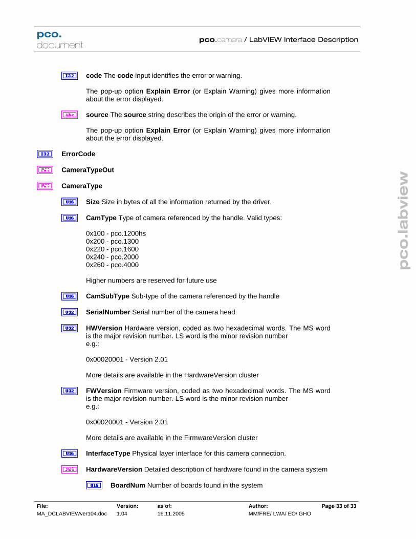
CameraTypeOut
CameraType
Size Size in bytes of all the information returned by the driver.
CamType Type of camera referenced by the handle. Valid types: 0x100 - pco.1200hs 0x200 - pco.1300 0x220 - pco.1600 0x240 - pco.2000 0x260 - pco.4000 Higher numbers are reserved for future use
CamSubType Sub-type of the camera referenced by the handle
SerialNumber Serial number of the camera head
HWVersion Hardware version, coded as two hexadecimal words. The MS wordis the major revision number. LS word is the minor revision number e.g.: 0x00020001 - Version 2.01 More details are available in the HardwareVersion cluster
FWVersion Firmware version, coded as two hexadecimal words. The MS wordis the major revision number. LS word is the minor revision number e.g.: 0x00020001 - Version 2.01 More details are available in the FirmwareVersion cluster
InterfaceType Physical layer interface for this camera connection.
HardwareVersion Detailed description of hardware found in the camera system
BoardNum Number of boards found in the system

pc
o.la
bvie
w
pco. document
pco.camera / LabVIEW Interface Description
File: MA_DCLABVIEWver104.doc
Version: 1.04
as of: 16.11.2005
Author: MM/FRE/ LWA/ EO/ GHO
Page 34 of 34
HWVersions Detailed hardware information for each board
BoardName Text description of board
BatchNumber Code describing batch that this board is from.
MinorRevision Minor hardware revision code for this board, e.g. if version is 2.01, minor revision is 1
MajorRevision Major hardware revision code for this board, e.g. if version is 2.01, major revision is 2
Variant If there is a special variant for this board, a code for this variant will appear here
FirmwareVersion
DeviceNum Number of devices (processors or gate arrays) found in the system
FWVersions Detailed firmware information for each device
DeviceName Text description of device
MinorRevision Minor firmware revision code for this device, e.g. if version is 2.01, minor revision is 1
MajorRevision Major firmware revision code for this device, e.g. if version is 2.01, major revision is 2
Variant If there is a special variant for this device, a code for this variant will appear here

pc
o.la
bvie
w
pco. document
pco.camera / LabVIEW Interface Description
File: MA_DCLABVIEWver104.doc
Version: 1.04
as of: 16.11.2005
Author: MM/FRE/ LWA/ EO/ GHO
Page 35 of 35
5.1.6 GetGeneral.vi
Returns information on the type, error status and physical state of the camera. Connector Pane
Front Panel
Controls and Indicators
ph Handle for the camera
error in (no error) The error in cluster can accept error information wired from VIspreviously called. Use this information to decide if any functionality should be bypassed in the event of errors from other VIs. The pop-up option Explain Error (or Explain Warning) gives more information about theerror displayed.
status The status boolean is either TRUE (X) for an error, or FALSE (checkmark) for no error or a warning. The pop-up option Explain Error (or Explain Warning) gives more information about the error displayed.

pc
o.la
bvie
w
pco. document
pco.camera / LabVIEW Interface Description
File: MA_DCLABVIEWver104.doc
Version: 1.04
as of: 16.11.2005
Author: MM/FRE/ LWA/ EO/ GHO
Page 36 of 36
code The code input identifies the error or warning. The pop-up option Explain Error (or Explain Warning) gives more information about the error displayed.
source The source string describes the origin of the error or warning. The pop-up option Explain Error (or Explain Warning) gives more information about the error displayed.
GeneralIn
hout Handle output
error out The error out cluster passes error or warning information out of a VI to beused by other VIs. The pop-up option Explain Error (or Explain Warning) gives more information about theerror displayed.
status The status boolean is either TRUE (X) for an error, or FALSE(checkmark) for no error or a warning. The pop-up option Explain Error (or Explain Warning) gives more information about the error displayed.
code The code input identifies the error or warning. The pop-up option Explain Error (or Explain Warning) gives more information about the error displayed.
source The source string describes the origin of the error or warning. The pop-up option Explain Error (or Explain Warning) gives more information about the error displayed.
ErrorCode
General
Size Size in bytes of all the information returned by the driver.
CameraType
Size Size in bytes of all the information returned by the driver.
CamType Type of camera referenced by the handle. Valid types: 0x100 - pco.1200hs 0x200 - pco.1300 0x220 - pco.1600 0x240 - pco.2000 0x260 - pco.4000

pc
o.la
bvie
w
pco. document
pco.camera / LabVIEW Interface Description
File: MA_DCLABVIEWver104.doc
Version: 1.04
as of: 16.11.2005
Author: MM/FRE/ LWA/ EO/ GHO
Page 37 of 37
Higher numbers are reserved for future use
CamSubType Sub-type of the camera referenced by the handle
SerialNumber Serial number of the camera head
HWVersion Hardware version, coded as two hexadecimal words. TheMS word is the major revision number. LS word is the minor revisionnumber e.g.: 0x00020001 - Version 2.01 More details are available in the HardwareVersion cluster
FWVersion Firmware version, coded as two hexadecimal words. TheMS word is the major revision number. LS word is the minor revisionnumber e.g.: 0x00020001 - Version 2.01 More details are available in the FirmwareVersion cluster
InterfaceType Physical layer interface for this camera connection.
HardwareVersion Detailed description of hardware found in the camerasystem
BoardNum Number of boards found in the system
HWVersions Detailed hardware information for each board
BoardName Text description of board
BatchNumber Code describing batch that this board is from.
MinorRevision Minor hardware revision code for this board, e.g. if version is 2.01, minor revision is 1
MajorRevision Major hardware revision code for this board, e.g. if version is 2.01, major revision is 2
Variant If there is a special variant for this board, a code for this variant will appear here
FirmwareVersion
DeviceNum Number of devices (processors or gate arrays)

pc
o.la
bvie
w
pco. document
pco.camera / LabVIEW Interface Description
File: MA_DCLABVIEWver104.doc
Version: 1.04
as of: 16.11.2005
Author: MM/FRE/ LWA/ EO/ GHO
Page 38 of 38
found in the system
FWVersions Detailed firmware information for each device
DeviceName Text description of device
MinorRevision Minor firmware revision code for this device, e.g. if version is 2.01, minor revision is 1
MajorRevision Major firmware revision code for this device, e.g. if version is 2.01, major revision is 2
Variant If there is a special variant for this device, a code for this variant will appear here
CameraHealthWarnings Indicates a potential problem, but one which is notserious enough to be considered an error. The warnings can be interpreted bit-wise as follows: 0x00000001 Power Supply Voltage Range 0x00000002 Power Supply Temperature 0x00000004 Camera temperature (board temperature / FPGA temperature) 0x00000008 Image Sensor temperature (for cooled camera versions only) Multiple error conditions can exist at the same time. For example, if there is awarning about the power supply temperature and the image sensor temperature,the code would be 0x0000000A.
CameraHealthErrors Indicates an error condition in the camera. The code canbe interpreted bit-wise as follows: 0x00000001 Power Supply Voltage Range 0x00000002 Power Supply Temperature 0x00000004 Camera temperature (board temperature / FPGA temperature) 0x00000008 Image Sensor temperature (for cooled camera versions only) 0x00010000 Camera Interface failure 0x00020000 Camera RAM module failure 0x00040000 Camera Main Board failure 0x00080000 Camera Head Boards failure Multiple error conditions can exist at the same time. For example, if the camera interface and the main board both have errors, the code would be 0x00050000
CameraHealthStatus Indicates the general status of the camera. The code canbe interpreted bit-wise as follows: 0x00000001 Default State: • Bit set: Settings were changed since power up or reset. • Bit cleared: No settings changed, camera is in default state.

pc
o.la
bvie
w
pco. document
pco.camera / LabVIEW Interface Description
File: MA_DCLABVIEWver104.doc
Version: 1.04
as of: 16.11.2005
Author: MM/FRE/ LWA/ EO/ GHO
Page 39 of 39
0x00000002 Settings Valid: • Bit set: Settings are valid (i.e. last “Arm Camera’ was successful and nosettings were changed since ‘Arm camera’, except exposure time). • Bit cleared: Settings were changed but not yet not checked and accepted by‘Arm Camera’ command. 0x00000004 Recording State: • Bit set: Recording state is on. • Bit cleared: Recording state is off. Multiple status indicators may be present. For example, if the settings have beenchanged, and the last setting was valid, the code would be 0x00000003
CCDTemperature Temperature in Celcius of the image sensor
CameraTemperature Temperature in Celcius of the camera head electronics
PowerSupplyTemperature Temperature in Celcius of the power supply electronics.

pc
o.la
bvie
w
pco. document
pco.camera / LabVIEW Interface Description
File: MA_DCLABVIEWver104.doc
Version: 1.04
as of: 16.11.2005
Author: MM/FRE/ LWA/ EO/ GHO
Page 40 of 40
5.1.7 GetTemperatures.vi
Get current sensor, electronics and power supply temperatures. Connector Pane
Front Panel
Controls and Indicators
Handle in
ErrorIn The error in cluster can accept error information wired from VIs previouslycalled. Use this information to decide if any functionality should be bypassed in the eventof errors from other VIs. The pop-up option Explain Error (or Explain Warning) gives more information about the error displayed.
status The status boolean is either TRUE (X) for an error, or FALSE(checkmark) for no error or a warning. The pop-up option Explain Error (or Explain Warning) gives more information about the error displayed.
code The code input identifies the error or warning. The pop-up option Explain Error (or Explain Warning) gives more information about the error displayed.

pc
o.la
bvie
w
pco. document
pco.camera / LabVIEW Interface Description
File: MA_DCLABVIEWver104.doc
Version: 1.04
as of: 16.11.2005
Author: MM/FRE/ LWA/ EO/ GHO
Page 41 of 41
source The source string describes the origin of the error or warning. The pop-up option Explain Error (or Explain Warning) gives more information about the error displayed.
Error out
Handle out
CCDTemp Sensor temperature in Celsius
CamTemp Electronics temperature in Celsius
PowTemp Power supply temperature in Celsius
ErrorOut The error in cluster can accept error information wired from VIs previouslycalled. Use this information to decide if any functionality should be bypassed in the eventof errors from other VIs. The pop-up option Explain Error (or Explain Warning) gives more information about theerror displayed.
status The status boolean is either TRUE (X) for an error, or FALSE(checkmark) for no error or a warning. The pop-up option Explain Error (or Explain Warning) gives more information about the error displayed.
code The code input identifies the error or warning. The pop-up option Explain Error (or Explain Warning) gives more information about the error displayed.
source The source string describes the origin of the error or warning. The pop-up option Explain Error (or Explain Warning) gives more information about the error displayed.

pc
o.la
bvie
w
pco. document
pco.camera / LabVIEW Interface Description
File: MA_DCLABVIEWver104.doc
Version: 1.04
as of: 16.11.2005
Author: MM/FRE/ LWA/ EO/ GHO
Page 42 of 42
5.1.8 InitiateSelfTestProcedure.vi
Initiates a camera self-test and returns any errors or warnings encountered. Connector Pane
Front Panel
Controls and Indicators
ph Handle for the camera
error in (no error) The error in cluster can accept error information wired from VIspreviously called. Use this information to decide if any functionality should be bypassedin the event of errors from other VIs. The pop-up option Explain Error (or Explain Warning) gives more information about theerror displayed.
status The status boolean is either TRUE (X) for an error, or FALSE(checkmark) for no error or a warning. The pop-up option Explain Error (or Explain Warning) gives more information about the error displayed.
code The code input identifies the error or warning. The pop-up option Explain Error (or Explain Warning) gives more information

pc
o.la
bvie
w
pco. document
pco.camera / LabVIEW Interface Description
File: MA_DCLABVIEWver104.doc
Version: 1.04
as of: 16.11.2005
Author: MM/FRE/ LWA/ EO/ GHO
Page 43 of 43
about the error displayed.
source The source string describes the origin of the error or warning. The pop-up option Explain Error (or Explain Warning) gives more information about the error displayed.
hout Handle output
error out The error out cluster passes error or warning information out of a VI to be used by other VIs. The pop-up option Explain Error (or Explain Warning) gives more information about theerror displayed.
status The status boolean is either TRUE (X) for an error, or FALSE(checkmark) for no error or a warning. The pop-up option Explain Error (or Explain Warning) gives more information about the error displayed.
code The code input identifies the error or warning. The pop-up option Explain Error (or Explain Warning) gives more information about the error displayed.
source The source string describes the origin of the error or warning. The pop-up option Explain Error (or Explain Warning) gives more information about the error displayed.
ErrorCode
Warn Indicates a potential problem, but one which is not serious enough to be considered an error. The warnings can be interpreted bit-wise as follows: 0x00000001 Power Supply Voltage Range 0x00000002 Power Supply Temperature 0x00000004 Camera temperature (board temperature / FPGA temperature) 0x00000008 Image Sensor temperature (for cooled camera versions only) Multiple error conditions can exist at the same time. For example, if there is a warningabout the power supply temperature and the image sensor temperature, the code wouldbe 0x0000000A.
Error Indicates an error condition in the camera. The code can be interpreted bit-wise as follows: 0x00000001 Power Supply Voltage Range 0x00000002 Power Supply Temperature 0x00000004 Camera temperature (board temperature / FPGA temperature) 0x00000008 Image Sensor temperature (for cooled camera versions only) 0x00010000 Camera Interface failure 0x00020000 Camera RAM module failure

pc
o.la
bvie
w
pco. document
pco.camera / LabVIEW Interface Description
File: MA_DCLABVIEWver104.doc
Version: 1.04
as of: 16.11.2005
Author: MM/FRE/ LWA/ EO/ GHO
Page 44 of 44
0x00040000 Camera Main Board failure 0x00080000 Camera Head Boards failure Multiple error conditions can exist at the same time. For example, if the camera interfaceand the main board both have errors, the code would be 0x00050000

pc
o.la
bvie
w
pco. document
pco.camera / LabVIEW Interface Description
File: MA_DCLABVIEWver104.doc
Version: 1.04
as of: 16.11.2005
Author: MM/FRE/ LWA/ EO/ GHO
Page 45 of 45
5.1.9 ResetSettingsToDefault.vi
Rests all camera settings to default values. These values are: Sensor Format: standard ROI: full resolution Binning: no binning (1 X 1) Pixel Rate: Lowest rate (sensor dependent) Gain: Normal gain (if setting available due to sensor) Double Image Mode: Off IR sensitivity: Off (if setting available due to sensor) Cooler Setpoint: -12 C° ADC mode: Using one ADC Exposure Time: 20 ms Delay Time: 0 µs Trigger Mode: Auto Trigger Recording state: stopped Memory Segmentation: Total memory allocated to first segment Storage Mode Recorder: Ring Buffer + Live View on Acquire Mode: Auto Connector Pane
Front Panel
Controls and Indicators
ph
ErrorIn The error in cluster can accept error information wired from VIs previouslycalled. Use this information to decide if any functionality should be bypassed in the event of errors from other VIs. The pop-up option Explain Error (or Explain Warning) gives more information about theerror displayed.
status The status boolean is either TRUE (X) for an error, or FALSE(checkmark) for no error or a warning.

pc
o.la
bvie
w
pco. document
pco.camera / LabVIEW Interface Description
File: MA_DCLABVIEWver104.doc
Version: 1.04
as of: 16.11.2005
Author: MM/FRE/ LWA/ EO/ GHO
Page 46 of 46
The pop-up option Explain Error (or Explain Warning) gives more information about the error displayed.
code The code input identifies the error or warning. The pop-up option Explain Error (or Explain Warning) gives more information about the error displayed.
source The source string describes the origin of the error or warning. The pop-up option Explain Error (or Explain Warning) gives more information about the error displayed.
hout
Error
ErrorOut The error in cluster can accept error information wired from VIs previously called. Use this information to decide if any functionality should be bypassed in the eventof errors from other VIs. The pop-up option Explain Error (or Explain Warning) gives more information about theerror displayed.
status The status boolean is either TRUE (X) for an error, or FALSE(checkmark) for no error or a warning. The pop-up option Explain Error (or Explain Warning) gives more information about the error displayed.
code The code input identifies the error or warning. The pop-up option Explain Error (or Explain Warning) gives more information about the error displayed.
source The source string describes the origin of the error or warning. The pop-up option Explain Error (or Explain Warning) gives more information about the error displayed.

pc
o.la
bvie
w
pco. document
pco.camera / LabVIEW Interface Description
File: MA_DCLABVIEWver104.doc
Version: 1.04
as of: 16.11.2005
Author: MM/FRE/ LWA/ EO/ GHO
Page 47 of 47
5.1.10 StripCamType.vi
Connector Pane
Front Panel Controls and Indicators
CameraTypeIn

pc
o.la
bvie
w
pco. document
pco.camera / LabVIEW Interface Description
File: MA_DCLABVIEWver104.doc
Version: 1.04
as of: 16.11.2005
Author: MM/FRE/ LWA/ EO/ GHO
Page 48 of 48
5.2 Sensor.llb
5.2.1 GetADCOperation.vi
Finds the number of A/D converters currently in use. Some models have multiple ADC's for faster readout. Connector Pane
Front Panel
Controls and Indicators
ph Handle for the camera
error in (no error) The error in cluster can accept error information wired from VIspreviously called. Use this information to decide if any functionality should be bypassed in the event of errors from other VIs. The pop-up option Explain Error (or Explain Warning) gives more information about theerror displayed.
status The status boolean is either TRUE (X) for an error, or FALSE(checkmark) for no error or a warning. The pop-up option Explain Error (or Explain Warning) gives more information about the error displayed.
code The code input identifies the error or warning. The pop-up option Explain Error (or Explain Warning) gives more information about the error displayed.

pc
o.la
bvie
w
pco. document
pco.camera / LabVIEW Interface Description
File: MA_DCLABVIEWver104.doc
Version: 1.04
as of: 16.11.2005
Author: MM/FRE/ LWA/ EO/ GHO
Page 49 of 49
source The source string describes the origin of the error or warning. The pop-up option Explain Error (or Explain Warning) gives more information about the error displayed.
hout Handle output
error out The error out cluster passes error or warning information out of a VI to beused by other VIs. The pop-up option Explain Error (or Explain Warning) gives more information about theerror displayed.
status The status boolean is either TRUE (X) for an error, or FALSE (checkmark) for no error or a warning. The pop-up option Explain Error (or Explain Warning) gives more information about the error displayed.
code The code input identifies the error or warning. The pop-up option Explain Error (or Explain Warning) gives more information about the error displayed.
source The source string describes the origin of the error or warning. The pop-up option Explain Error (or Explain Warning) gives more information about the error displayed.
ErrorCode
ADCOperation Number of A/D converters currently in use.

pc
o.la
bvie
w
pco. document
pco.camera / LabVIEW Interface Description
File: MA_DCLABVIEWver104.doc
Version: 1.04
as of: 16.11.2005
Author: MM/FRE/ LWA/ EO/ GHO
Page 50 of 50
5.2.2 GetBinning.vi
Finds the camera's current binning setting. as set by the Set Binning and ArmCamera commands. Use GetDescription.vi to determine what the allowed binning settings are for the camera. Connector Pane
Front Panel
Controls and Indicators
ph Handle for the camera
error in (no error) The error in cluster can accept error information wired from VIspreviously called. Use this information to decide if any functionality should be bypassed in the event of errors from other VIs. The pop-up option Explain Error (or Explain Warning) gives more information about theerror displayed.
status The status boolean is either TRUE (X) for an error, or FALSE(checkmark) for no error or a warning. The pop-up option Explain Error (or Explain Warning) gives more information about the error displayed.
code The code input identifies the error or warning. The pop-up option Explain Error (or Explain Warning) gives more information about the error displayed.
source The source string describes the origin of the error or warning. The pop-up option Explain Error (or Explain Warning) gives more information

pc
o.la
bvie
w
pco. document
pco.camera / LabVIEW Interface Description
File: MA_DCLABVIEWver104.doc
Version: 1.04
as of: 16.11.2005
Author: MM/FRE/ LWA/ EO/ GHO
Page 51 of 51
about the error displayed.
hout Handle output
error out The error out cluster passes error or warning information out of a VI to beused by other VIs. The pop-up option Explain Error (or Explain Warning) gives more information about theerror displayed.
status The status boolean is either TRUE (X) for an error, or FALSE (checkmark) for no error or a warning. The pop-up option Explain Error (or Explain Warning) gives more information about the error displayed.
code The code input identifies the error or warning. The pop-up option Explain Error (or Explain Warning) gives more information about the error displayed.
source The source string describes the origin of the error or warning. The pop-up option Explain Error (or Explain Warning) gives more information about the error displayed.
ErrorCode
BinHorz Current horizontal binning setting
BinVert Current vertical binning setting

pc
o.la
bvie
w
pco. document
pco.camera / LabVIEW Interface Description
File: MA_DCLABVIEWver104.doc
Version: 1.04
as of: 16.11.2005
Author: MM/FRE/ LWA/ EO/ GHO
Page 52 of 52
5.2.3 GetConversionFactor.vi
Finds the current A/D converter gain setting, in electrons/pixel. The number returned is an integer and represents 100 times the actual value, e.g. 435 = 4.35 electrons/count. Connector Pane
Front Panel
Controls and Indicators
ph Handle for the camera
error in (no error) The error in cluster can accept error information wired from VIspreviously called. Use this information to decide if any functionality should be bypassedin the event of errors from other VIs. The pop-up option Explain Error (or Explain Warning) gives more information about theerror displayed.
status The status boolean is either TRUE (X) for an error, or FALSE (checkmark) for no error or a warning. The pop-up option Explain Error (or Explain Warning) gives more information about the error displayed.
code The code input identifies the error or warning. The pop-up option Explain Error (or Explain Warning) gives more information about the error displayed.
source The source string describes the origin of the error or warning. The pop-up option Explain Error (or Explain Warning) gives more information

pc
o.la
bvie
w
pco. document
pco.camera / LabVIEW Interface Description
File: MA_DCLABVIEWver104.doc
Version: 1.04
as of: 16.11.2005
Author: MM/FRE/ LWA/ EO/ GHO
Page 53 of 53
about the error displayed.
hout Handle output
error out The error out cluster passes error or warning information out of a VI to beused by other VIs. The pop-up option Explain Error (or Explain Warning) gives more information about theerror displayed.
status The status boolean is either TRUE (X) for an error, or FALSE(checkmark) for no error or a warning. The pop-up option Explain Error (or Explain Warning) gives more information about the error displayed.
code The code input identifies the error or warning. The pop-up option Explain Error (or Explain Warning) gives more information about the error displayed.
source The source string describes the origin of the error or warning. The pop-up option Explain Error (or Explain Warning) gives more information about the error displayed.
ErrorCode
ConvFact Finds the current A/D converter gain setting, in electrons/pixel. The numberreturned is an integer and represents 100 times the actual value, e.g. 435 = 4.35electrons/count.

pc
o.la
bvie
w
pco. document
pco.camera / LabVIEW Interface Description
File: MA_DCLABVIEWver104.doc
Version: 1.04
as of: 16.11.2005
Author: MM/FRE/ LWA/ EO/ GHO
Page 54 of 54
5.2.4 GetCoolingSetpointTemperature.vi
Finds the current cooling temperature setpoint, in °C. Value will be 0 for cameras which are not cooled. Connector Pane
Front Panel
Controls and Indicators
ph Handle for the camera
error in (no error) The error in cluster can accept error information wired from VIs previously called. Use this information to decide if any functionality should be bypassedin the event of errors from other VIs. The pop-up option Explain Error (or Explain Warning) gives more information about theerror displayed.
status The status boolean is either TRUE (X) for an error, or FALSE(checkmark) for no error or a warning. The pop-up option Explain Error (or Explain Warning) gives more information about the error displayed.
code The code input identifies the error or warning. The pop-up option Explain Error (or Explain Warning) gives more information about the error displayed.
source The source string describes the origin of the error or warning. The pop-up option Explain Error (or Explain Warning) gives more information about the error displayed.

pc
o.la
bvie
w
pco. document
pco.camera / LabVIEW Interface Description
File: MA_DCLABVIEWver104.doc
Version: 1.04
as of: 16.11.2005
Author: MM/FRE/ LWA/ EO/ GHO
Page 55 of 55
hout Handle output
error out The error out cluster passes error or warning information out of a VI to beused by other VIs. The pop-up option Explain Error (or Explain Warning) gives more information about the error displayed.
status The status boolean is either TRUE (X) for an error, or FALSE(checkmark) for no error or a warning. The pop-up option Explain Error (or Explain Warning) gives more information about the error displayed.
code The code input identifies the error or warning. The pop-up option Explain Error (or Explain Warning) gives more information about the error displayed.
source The source string describes the origin of the error or warning. The pop-up option Explain Error (or Explain Warning) gives more information about the error displayed.
ErrorCode
CoolSet Current cooling temperature setpoint, in °C. Value will be 0 for cameras whichare not cooled.

pc
o.la
bvie
w
pco. document
pco.camera / LabVIEW Interface Description
File: MA_DCLABVIEWver104.doc
Version: 1.04
as of: 16.11.2005
Author: MM/FRE/ LWA/ EO/ GHO
Page 56 of 56
5.2.5 GetDescription.vi
Returns detailed information on the camera refernced by the input handle. The "Description" cluster contains information on sensor type, supported modes of operation, and various other operating parameters. Connector Pane
Front Panel Controls and Indicators

pc
o.la
bvie
w
pco. document
pco.camera / LabVIEW Interface Description
File: MA_DCLABVIEWver104.doc
Version: 1.04
as of: 16.11.2005
Author: MM/FRE/ LWA/ EO/ GHO
Page 57 of 57
ph Handle to camera
Description Detailed description of the properties of the camera including sensor type,digitization rate, etc.
Size Size of this cluster in bytes
SensorTypeDESC Identification code for image sensor in camera head Here are the sensor codes defined for this release: Monochrome sensors: 0x0010 Sony ICX285AL 0x0020 Sony ICX263AL 0x0030 Sony ICX274AL 0x0040 Sony ICX407AL 0x0050 Sony ICX414AL 0x0110 Kodak KAI-2000M 0x0120 Kodak KAI-2001M 0x0130 Kodak KAI-4010M 0x0140 Kodak KAI-4020M 0x0150 Kodak KAI-11000M 0x1010 Micron MV13 bw Color sensors: 0x0011 Sony ICX285AK 0x0021 Sony ICX263AK 0x0031 Sony ICX274AK 0x0041 Sony ICX407AK 0x0051 Sony ICX414AK 0x0111 Kodak KAI-2000CM 0x0121 Kodak KAI-2001CM 0x0131 Kodak KAI-4010CM 0x0141 Kodak KAI-4020CM 0x0151 Kodak KAI-11000CM 0x1011 Micron MV13 col
SensorSubtypeDESC Code for sensor subtypes, variants etc.
MaxHorizontalResStdDESC Maximum horizontal effective pixels in standard mode
MaxVerticalResStdDESC Maximum vertical effective pixels in standard mode
MaxHorizontalResExtDESC Maximum horizontal pixels in extended mode. This includes all dark pixels, reference pixels and effective pixels
MaxVerticalResExtDESC Maximum vertical pixels in extended mode. This includes all dark pixels, reference pixels and effective pixels
DynResDESC Analog to digital converter resolution, in bits.

pc
o.la
bvie
w
pco. document
pco.camera / LabVIEW Interface Description
File: MA_DCLABVIEWver104.doc
Version: 1.04
as of: 16.11.2005
Author: MM/FRE/ LWA/ EO/ GHO
Page 58 of 58
MaxBinHorzDESC Maximum bin size in the horizontal direction
BinHorzStepDESC Describes the binning increments allowed in the horizontaldirection. FALSE = Only binary increments are allowed, i.e. 1, 2, 4, 8..... TRUE = Linear increments are allowed, i.e. 1, 2, 3,4, 5, 6,.....
MaxBinVertDESC Maximum bin size in the vertical direction
BinVertStepDESC Describes the binning increments allowed in the verticaldirection. FALSE = Only binary increments are allowed, i.e. 1, 2, 4, 8..... TRUE = Linear increments are allowed, i.e. 1, 2, 3,4, 5, 6,.....
ROIHorzStepDESC Describes the minimum increment allowed in the region ofinterest setting in the horizontal direction. For example: A value of 10 means the right ROI border can be 1, 11, 21, etc. A value of 32 means the right ROI border can be 1, 33, 65, etc.
ROIVertStepDESC Describes the minimum increment allowed in the region ofinterest setting in the vertical direction. For example: A value of 10 means the top ROI border can be 1, 11, 21, etc. A value of 32 means the top ROI border can be 1, 33, 65, etc.
NumADCDESC Number of A/D converters available
IRDESC Indicates whether camera has enhanced infrared mode FALSE - IR enhancement not suppoted TRUE - Camera supports enhanced infrared mode
MinDelayDESC Minimum delay setting in nanoseconds for standard mode
MaxDelayDESC Maximum delay setting in milliseconds for standard mode
MinDelayStepDESC Minimum delay step size in nanoseconds (all modes)
MinExpoDESC Minimum exposure setting in nanoseconds for standard mode
MaxExpoDESC Maximum exposure setting in milliseconds for standard mode
MinExpoStepDESC Minimum exposure step size in nanoseconds (all modes)
MinDelayIRDESC Minimum delay setting in nanoseconds for IR enhanced mode
MaxDelayIRDESC Maximum delay setting in milliseconds for IR enhanced mode
MinExpoIRDESC Minimum exposure setting in nanoseconds for IR enhancedmode

pc
o.la
bvie
w
pco. document
pco.camera / LabVIEW Interface Description
File: MA_DCLABVIEWver104.doc
Version: 1.04
as of: 16.11.2005
Author: MM/FRE/ LWA/ EO/ GHO
Page 59 of 59
MaxExpoIRDESC Maximum exposure setting in milliseconds for IR enhancedmode
TimeTableDESC Indicates camera's ability to use delay / exposure time tables FALSE - Exposure time tables not supported TRUE - Exposure time tables supported
DoubleImageDESC Indicates double image capability FALSE - Double image mode not supported. TRUE - Camera has double image capability.
MinCoolSetDESC Minimum cooling setpoint, in °C. Value is 0 for uncooledcameras
MaxCoolSetDESC Maximum cooling setpoint, in °C. Value is 0 for uncooledcameras
MDefaultCoolSetDESC Default cooling setpoint, in °C. Value is 0 for uncooledcameras
PowerDownModeDESC Indicates whether the sensor can be powered down toreduce dark current FALSE - Power down mode is not supported TRUE - Power down mode is supported
OffsetRegDESC Indicates whether camera is capable of automatic offsetregulation. Offset regulation is perform by sampling dark reference pixels togauge the thermal drift in the sensor, then adjusting the offset voltage tocompensate. FALSE - Camera does not support automatic offset regulation TRUE - Offset regulation is supported.
ColorPattern Describes the pattern of color filters used on the pixels of a colorsensor. This number packs 4, 4 bit numbers describing each quadrant of a 2 X 2pixel color pattern cell.
UpperLeftColor Color of the upper left pixel in the 2 X 2 color pattern Possible values are: 0 - Monochrome, no color filter 1 - Red 2 - Green A 3 - Green B 4 - Blue 5 - Cyan 6 - Magenta 7 - Yellow

pc
o.la
bvie
w
pco. document
pco.camera / LabVIEW Interface Description
File: MA_DCLABVIEWver104.doc
Version: 1.04
as of: 16.11.2005
Author: MM/FRE/ LWA/ EO/ GHO
Page 60 of 60
UpperRightColor Color of the upper right pixel in the 2 X 2 color pattern Possible values are: 0 - Monochrome, no color filter 1 - Red 2 - Green A 3 - Green B 4 - Blue 5 - Cyan 6 - Magenta 7 - Yellow
LowerLeftColor Color of the lower left pixel in the 2 X 2 color pattern Possible values are: 0 - Monochrome, no color filter 1 - Red 2 - Green A 3 - Green B 4 - Blue 5 - Cyan 6 - Magenta 7 - Yellow
LowerRightColor Color of the lower right pixel in the 2 X 2 color pattern Possible values are: 0 - Monochrome, no color filter 1 - Red 2 - Green A 3 - Green B 4 - Blue 5 - Cyan 6 - Magenta 7 - Yellow
PatternTypeDESC Iindicates, for color sensors, whether sensor has an RGB or a CMY Bayer pattern. For monochrome sensors, the output isalways FALSE. FALSE - RGB pattern TRUE - CMY pattern
PixelRates Analog to digital converter rates, in samples per second. Forcameras that support multiple A/D rates, each element of the array willcontain the sampling rate for each supported mode.
PixelRateDesc1
CoversionFactors Digitizer conversion factors, in electrons / count. For cameras that support multiple ranges, each element of the array will be

pc
o.la
bvie
w
pco. document
pco.camera / LabVIEW Interface Description
File: MA_DCLABVIEWver104.doc
Version: 1.04
as of: 16.11.2005
Author: MM/FRE/ LWA/ EO/ GHO
Page 61 of 61
filled with the corresponding conversion factor for that mode.
ConvFactDesc1
Reserved Reserved for future use
Reserved1
NoiseFilterCapable Indicates whether camera is capable of noise filtering FALSE - Camera does not support noise filter TRUE - Noise filter is supported.
HotPixelCapable Indicates whether camera is capable of automatic hotpixel correction. NOTE: Also check the "HotPixelWithNoiseFilter"indicator to determine if the noise filter is required for this mode of operation. FALSE - Camera does not support hot pixel correction TRUE - hot PixelCorrection is supported.
HotPixelWithNoiseFilter Indicates whether noise filter is required for hot pixelcorrection FALSE - Noise filter is not required TRUE - Noise filter is required
ASCIITimeCapable Indicates whether camera is capable of automatic offset regulation. Offset regulation is perform by sampling dark referencepixels to gauge the thermal drift in the sensor, then adjusting the offset voltage to compensate. FALSE - Camera does not support automatic offset regulation TRUE - Offset regulation is supported.
hout Handle returned by GetDescription
ErrorOut The error in cluster can accept error information wired from VIs previously called. Use this information to decide if any functionality should bebypassed in the event of errors from other VIs. The pop-up option Explain Error (or Explain Warning) gives more information about the error displayed.
ErrorIn The error in cluster can accept error information wired from VIspreviously called. Use this information to decide if any functionality should bebypassed in the event of errors from other VIs. The pop-up option Explain Error (or Explain Warning) gives more information about the error displayed.
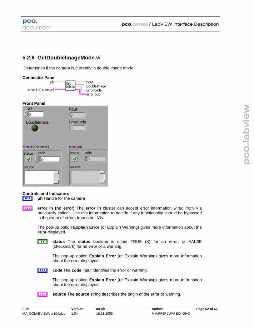
pc
o.la
bvie
w
pco. document
pco.camera / LabVIEW Interface Description
File: MA_DCLABVIEWver104.doc
Version: 1.04
as of: 16.11.2005
Author: MM/FRE/ LWA/ EO/ GHO
Page 62 of 62
5.2.6 GetDoubleImageMode.vi
Determines if the camera is currently in double image mode. Connector Pane
Front Panel
Controls and Indicators
ph Handle for the camera
error in (no error) The error in cluster can accept error information wired from VIspreviously called. Use this information to decide if any functionality should be bypassedin the event of errors from other VIs. The pop-up option Explain Error (or Explain Warning) gives more information about the error displayed.
status The status boolean is either TRUE (X) for an error, or FALSE(checkmark) for no error or a warning. The pop-up option Explain Error (or Explain Warning) gives more information about the error displayed.
code The code input identifies the error or warning. The pop-up option Explain Error (or Explain Warning) gives more information about the error displayed.
source The source string describes the origin of the error or warning.
pc
o.la
bvie
w
pco. document
pco.camera / LabVIEW Interface Description
File: MA_DCLABVIEWver104.doc
Version: 1.04
as of: 16.11.2005
Author: MM/FRE/ LWA/ EO/ GHO
Page 63 of 63
The pop-up option Explain Error (or Explain Warning) gives more information about the error displayed.
hout Handle output
error out The error out cluster passes error or warning information out of a VI to beused by other VIs. The pop-up option Explain Error (or Explain Warning) gives more information about the error displayed.
status The status boolean is either TRUE (X) for an error, or FALSE(checkmark) for no error or a warning. The pop-up option Explain Error (or Explain Warning) gives more information about the error displayed.
code The code input identifies the error or warning. The pop-up option Explain Error (or Explain Warning) gives more information about the error displayed.
source The source string describes the origin of the error or warning. The pop-up option Explain Error (or Explain Warning) gives more information about the error displayed.
ErrorCode
DoubleImage Indicates the state of the double image mode. FALSE - Double image mode disabled TRUE - Camera is currently in double image mode.

pc
o.la
bvie
w
pco. document
pco.camera / LabVIEW Interface Description
File: MA_DCLABVIEWver104.doc
Version: 1.04
as of: 16.11.2005
Author: MM/FRE/ LWA/ EO/ GHO
Page 64 of 64
5.2.7 GetIRSensitivity.vi
Indicates the status of the enhanced infrared sensitivity mode. Connector Pane
Front Panel
Controls and Indicators
ph Handle for the camera
error in (no error) The error in cluster can accept error information wired from VIs previously called. Use this information to decide if any functionality should be bypassedin the event of errors from other VIs. The pop-up option Explain Error (or Explain Warning) gives more information about theerror displayed.
status The status boolean is either TRUE (X) for an error, or FALSE(checkmark) for no error or a warning. The pop-up option Explain Error (or Explain Warning) gives more information about the error displayed.
code The code input identifies the error or warning. The pop-up option Explain Error (or Explain Warning) gives more information about the error displayed.
source The source string describes the origin of the error or warning. The pop-up option Explain Error (or Explain Warning) gives more information about the error displayed.

pc
o.la
bvie
w
pco. document
pco.camera / LabVIEW Interface Description
File: MA_DCLABVIEWver104.doc
Version: 1.04
as of: 16.11.2005
Author: MM/FRE/ LWA/ EO/ GHO
Page 65 of 65
hout Handle output
error out The error out cluster passes error or warning information out of a VI to beused by other VIs. The pop-up option Explain Error (or Explain Warning) gives more information about the error displayed.
status The status boolean is either TRUE (X) for an error, or FALSE(checkmark) for no error or a warning. The pop-up option Explain Error (or Explain Warning) gives more information about the error displayed.
code The code input identifies the error or warning. The pop-up option Explain Error (or Explain Warning) gives more information about the error displayed.
source The source string describes the origin of the error or warning. The pop-up option Explain Error (or Explain Warning) gives more information about the error displayed.
ErrorCode
IR Indicates the status of the enhanced infrared sensitivity mode. FALSE - Enhanced infrared sensitivity mode is disabled FALSE - Enhanced infrared sensitivity mode is enabled

pc
o.la
bvie
w
pco. document
pco.camera / LabVIEW Interface Description
File: MA_DCLABVIEWver104.doc
Version: 1.04
as of: 16.11.2005
Author: MM/FRE/ LWA/ EO/ GHO
Page 66 of 66
5.2.8 GetOffsetMode.vi
Returns the current state of the automatic offset regulation. Connector Pane
Front Panel
Controls and Indicators
ph Handle for the camera
error in (no error) The error in cluster can accept error information wired from VIs previously called. Use this information to decide if any functionality should be bypassedin the event of errors from other VIs. The pop-up option Explain Error (or Explain Warning) gives more information about theerror displayed.
status The status boolean is either TRUE (X) for an error, or FALSE(checkmark) for no error or a warning. The pop-up option Explain Error (or Explain Warning) gives more information about the error displayed.
code The code input identifies the error or warning. The pop-up option Explain Error (or Explain Warning) gives more information about the error displayed.
source The source string describes the origin of the error or warning. The pop-up option Explain Error (or Explain Warning) gives more information about the error displayed.

pc
o.la
bvie
w
pco. document
pco.camera / LabVIEW Interface Description
File: MA_DCLABVIEWver104.doc
Version: 1.04
as of: 16.11.2005
Author: MM/FRE/ LWA/ EO/ GHO
Page 67 of 67
hout Handle output
error out The error out cluster passes error or warning information out of a VI to beused by other VIs. The pop-up option Explain Error (or Explain Warning) gives more information about the error displayed.
status The status boolean is either TRUE (X) for an error, or FALSE(checkmark) for no error or a warning. The pop-up option Explain Error (or Explain Warning) gives more information about the error displayed.
code The code input identifies the error or warning. The pop-up option Explain Error (or Explain Warning) gives more information about the error displayed.
source The source string describes the origin of the error or warning. The pop-up option Explain Error (or Explain Warning) gives more information about the error displayed.
ErrorCode
OffsetRegulation Current state of the automatic offset regulation. FALSE - Automatic offset control enabled TRUE - Automatic offset control disabled

pc
o.la
bvie
w
pco. document
pco.camera / LabVIEW Interface Description
File: MA_DCLABVIEWver104.doc
Version: 1.04
as of: 16.11.2005
Author: MM/FRE/ LWA/ EO/ GHO
Page 68 of 68
5.2.9 GetPixelRate.vi
Finds the current pixel rate, as of the last ArmCamera command. The pixelrate is gven in Hz, e.g. 10000000 = 10 Mhz Connector Pane
Front Panel
Controls and Indicators
ph Handle for the camera
error in (no error) The error in cluster can accept error information wired from VIs previously called. Use this information to decide if any functionality should be bypassedin the event of errors from other VIs. The pop-up option Explain Error (or Explain Warning) gives more information about the error displayed.
status The status boolean is either TRUE (X) for an error, or FALSE(checkmark) for no error or a warning. The pop-up option Explain Error (or Explain Warning) gives more information about the error displayed.
code The code input identifies the error or warning. The pop-up option Explain Error (or Explain Warning) gives more information about the error displayed.
source The source string describes the origin of the error or warning. The pop-up option Explain Error (or Explain Warning) gives more information about the error displayed.

pc
o.la
bvie
w
pco. document
pco.camera / LabVIEW Interface Description
File: MA_DCLABVIEWver104.doc
Version: 1.04
as of: 16.11.2005
Author: MM/FRE/ LWA/ EO/ GHO
Page 69 of 69
hout Handle output
error out The error out cluster passes error or warning information out of a VI to beused by other VIs. The pop-up option Explain Error (or Explain Warning) gives more information about the error displayed.
status The status boolean is either TRUE (X) for an error, or FALSE(checkmark) for no error or a warning. The pop-up option Explain Error (or Explain Warning) gives more information about the error displayed.
code The code input identifies the error or warning. The pop-up option Explain Error (or Explain Warning) gives more information about the error displayed.
source The source string describes the origin of the error or warning. The pop-up option Explain Error (or Explain Warning) gives more information about the error displayed.
ErrorCode
PixelRate Current pixel rate, as of the last ArmCamera command. The pixelrate is gvenin Hz, e.g. 10000000 = 10 Mhz

pc
o.la
bvie
w
pco. document
pco.camera / LabVIEW Interface Description
File: MA_DCLABVIEWver104.doc
Version: 1.04
as of: 16.11.2005
Author: MM/FRE/ LWA/ EO/ GHO
Page 70 of 70
5.2.10 GetROI.vi
Get ROI (region or area of interest) window settings. The ROI is equal to or smaller than the absolute image area which is defined by the settings of format and binning. Connector Pane
Front Panel
Controls and Indicators
ph Handle for the camera
error in (no error) The error in cluster can accept error information wired from VIspreviously called. Use this information to decide if any functionality should be bypassedin the event of errors from other VIs. The pop-up option Explain Error (or Explain Warning) gives more information about the error displayed.
status The status boolean is either TRUE (X) for an error, or FALSE(checkmark) for no error or a warning. The pop-up option Explain Error (or Explain Warning) gives more information about the error displayed.
code The code input identifies the error or warning. The pop-up option Explain Error (or Explain Warning) gives more information about the error displayed.

pc
o.la
bvie
w
pco. document
pco.camera / LabVIEW Interface Description
File: MA_DCLABVIEWver104.doc
Version: 1.04
as of: 16.11.2005
Author: MM/FRE/ LWA/ EO/ GHO
Page 71 of 71
source The source string describes the origin of the error or warning. The pop-up option Explain Error (or Explain Warning) gives more information about the error displayed.
hout Handle output
error out The error out cluster passes error or warning information out of a VI to beused by other VIs. The pop-up option Explain Error (or Explain Warning) gives more information about theerror displayed.
status The status boolean is either TRUE (X) for an error, or FALSE(checkmark) for no error or a warning. The pop-up option Explain Error (or Explain Warning) gives more information about the error displayed.
code The code input identifies the error or warning. The pop-up option Explain Error (or Explain Warning) gives more information about the error displayed.
source The source string describes the origin of the error or warning. The pop-up option Explain Error (or Explain Warning) gives more information about the error displayed.
ErrorCode
ROIX0 Left border of the region of interest
ROIY0 Top border of the region of interest
ROIX1 Right border of the region of interest
ROIY1 Bottom border of the region of interest

pc
o.la
bvie
w
pco. document
pco.camera / LabVIEW Interface Description
File: MA_DCLABVIEWver104.doc
Version: 1.04
as of: 16.11.2005
Author: MM/FRE/ LWA/ EO/ GHO
Page 72 of 72
5.2.11 GetSensorFormat.vi
Returns the format of the sensor as either Standard or Extended. Extended format displays all pixels, including dark refernce and dummies. Connector Pane
Front Panel
Controls and Indicators
ph
ErrorIn The error in cluster can accept error information wired from VIs previouslycalled. Use this information to decide if any functionality should be bypassed in the eventof errors from other VIs. The pop-up option Explain Error (or Explain Warning) gives more information about theerror displayed.
status The status boolean is either TRUE (X) for an error, or FALSE(checkmark) for no error or a warning. The pop-up option Explain Error (or Explain Warning) gives more information about the error displayed.
code The code input identifies the error or warning. The pop-up option Explain Error (or Explain Warning) gives more information about the error displayed.
source The source string describes the origin of the error or warning.

pc
o.la
bvie
w
pco. document
pco.camera / LabVIEW Interface Description
File: MA_DCLABVIEWver104.doc
Version: 1.04
as of: 16.11.2005
Author: MM/FRE/ LWA/ EO/ GHO
Page 73 of 73
The pop-up option Explain Error (or Explain Warning) gives more information about the error displayed.
Error
hout
Sensor Current sensor format setting: 0 - Standard format displays only active pixels 1 - Extended format: displays active dark reference and dummy pixels.
ErrorOut The error in cluster can accept error information wired from VIs previouslycalled. Use this information to decide if any functionality should be bypassed in the event of errors from other VIs. The pop-up option Explain Error (or Explain Warning) gives more information about theerror displayed.
status The status boolean is either TRUE (X) for an error, or FALSE(checkmark) for no error or a warning. The pop-up option Explain Error (or Explain Warning) gives more information about the error displayed.
code The code input identifies the error or warning. The pop-up option Explain Error (or Explain Warning) gives more information about the error displayed.
source The source string describes the origin of the error or warning. The pop-up option Explain Error (or Explain Warning) gives more information about the error displayed.

pc
o.la
bvie
w
pco. document
pco.camera / LabVIEW Interface Description
File: MA_DCLABVIEWver104.doc
Version: 1.04
as of: 16.11.2005
Author: MM/FRE/ LWA/ EO/ GHO
Page 74 of 74
5.2.12 GetSizes.vi
Finds the actual size of the image as set by the last ArmCamera command. Connector Pane
Front Panel
Controls and Indicators
ph
ErrorIn The error in cluster can accept error information wired from VIs previouslycalled. Use this information to decide if any functionality should be bypassed in the event of errors from other VIs. The pop-up option Explain Error (or Explain Warning) gives more information about theerror displayed.
status The status boolean is either TRUE (X) for an error, or FALSE(checkmark) for no error or a warning. The pop-up option Explain Error (or Explain Warning) gives more information about the error displayed.
code The code input identifies the error or warning. The pop-up option Explain Error (or Explain Warning) gives more information about the error displayed.
source The source string describes the origin of the error or warning.

pc
o.la
bvie
w
pco. document
pco.camera / LabVIEW Interface Description
File: MA_DCLABVIEWver104.doc
Version: 1.04
as of: 16.11.2005
Author: MM/FRE/ LWA/ EO/ GHO
Page 75 of 75
The pop-up option Explain Error (or Explain Warning) gives more information about the error displayed.
Error
hout
XResAct Actual horizontal resolution of the image as determined by the settings at the last ArmCamera command.
YResAct Actual vertical resolution of the image as determined by the settings at the lastArmCamera command.
XResMax Maximum horizontal resolution for this sensor
YResMax Maximum vertical resolution for this sensor
ErrorOut The error in cluster can accept error information wired from VIs previouslycalled. Use this information to decide if any functionality should be bypassed in the eventof errors from other VIs. The pop-up option Explain Error (or Explain Warning) gives more information about theerror displayed.
status The status boolean is either TRUE (X) for an error, or FALSE(checkmark) for no error or a warning. The pop-up option Explain Error (or Explain Warning) gives more information about the error displayed.
code The code input identifies the error or warning. The pop-up option Explain Error (or Explain Warning) gives more information about the error displayed.
source The source string describes the origin of the error or warning. The pop-up option Explain Error (or Explain Warning) gives more information about the error displayed.

pc
o.la
bvie
w
pco. document
pco.camera / LabVIEW Interface Description
File: MA_DCLABVIEWver104.doc
Version: 1.04
as of: 16.11.2005
Author: MM/FRE/ LWA/ EO/ GHO
Page 76 of 76
5.2.13 SetADCOperation.vi
Sets the number of A/D converters used to read out the image sensor. One ADC gives the higherst linearity, but multiple ADC's can be used in some models for faster readout. Use GetDescription.vi to find the maximum number of ADC's available. Connector Pane
Front Panel
Controls and Indicators
ph Handle for the camera
error in (no error) The error in cluster can accept error information wired from VIspreviously called. Use this information to decide if any functionality should be bypassedin the event of errors from other VIs. The pop-up option Explain Error (or Explain Warning) gives more information about the error displayed.
status The status boolean is either TRUE (X) for an error, or FALSE(checkmark) for no error or a warning. The pop-up option Explain Error (or Explain Warning) gives more information about the error displayed.
code The code input identifies the error or warning. The pop-up option Explain Error (or Explain Warning) gives more information about the error displayed.
source The source string describes the origin of the error or warning. The pop-up option Explain Error (or Explain Warning) gives more information

pc
o.la
bvie
w
pco. document
pco.camera / LabVIEW Interface Description
File: MA_DCLABVIEWver104.doc
Version: 1.04
as of: 16.11.2005
Author: MM/FRE/ LWA/ EO/ GHO
Page 77 of 77
about the error displayed.
ADCOperation Sets the number of A/D converters used to read out the image sensor.One ADC gives the higherst linearity, but multiple ADC's can be used in some models for faster readout. Use GetDescription.vi to find the maximum number of ADC's available.
hout Handle output
error out The error out cluster passes error or warning information out of a VI to beused by other VIs. The pop-up option Explain Error (or Explain Warning) gives more information about theerror displayed.
status The status boolean is either TRUE (X) for an error, or FALSE(checkmark) for no error or a warning. The pop-up option Explain Error (or Explain Warning) gives more information about the error displayed.
code The code input identifies the error or warning. The pop-up option Explain Error (or Explain Warning) gives more information about the error displayed.
source The source string describes the origin of the error or warning. The pop-up option Explain Error (or Explain Warning) gives more information about the error displayed.
ErrorCode

pc
o.la
bvie
w
pco. document
pco.camera / LabVIEW Interface Description
File: MA_DCLABVIEWver104.doc
Version: 1.04
as of: 16.11.2005
Author: MM/FRE/ LWA/ EO/ GHO
Page 78 of 78
5.2.14 SetBinning.vi
Sets the binning to be used by the camera at the next ArmCamera command. Use GetDescription.vi to determine what the allowed binning settings are for the camera. Connector Pane
Front Panel
Controls and Indicators
ph Handle for the camera
error in (no error) The error in cluster can accept error information wired from VIspreviously called. Use this information to decide if any functionality should be bypassedin the event of errors from other VIs. The pop-up option Explain Error (or Explain Warning) gives more information about theerror displayed.
status The status boolean is either TRUE (X) for an error, or FALSE(checkmark) for no error or a warning. The pop-up option Explain Error (or Explain Warning) gives more information about the error displayed.
code The code input identifies the error or warning. The pop-up option Explain Error (or Explain Warning) gives more information about the error displayed.
source The source string describes the origin of the error or warning. The pop-up option Explain Error (or Explain Warning) gives more information

pc
o.la
bvie
w
pco. document
pco.camera / LabVIEW Interface Description
File: MA_DCLABVIEWver104.doc
Version: 1.04
as of: 16.11.2005
Author: MM/FRE/ LWA/ EO/ GHO
Page 79 of 79
about the error displayed.
BinHorz Set horizontal binning.
BinVert Set vertical binning.
hout Handle output
error out The error out cluster passes error or warning information out of a VI to beused by other VIs. The pop-up option Explain Error (or Explain Warning) gives more information about theerror displayed.
status The status boolean is either TRUE (X) for an error, or FALSE(checkmark) for no error or a warning. The pop-up option Explain Error (or Explain Warning) gives more information about the error displayed.
code The code input identifies the error or warning. The pop-up option Explain Error (or Explain Warning) gives more information about the error displayed.
source The source string describes the origin of the error or warning. The pop-up option Explain Error (or Explain Warning) gives more information about the error displayed.
ErrorCode

pc
o.la
bvie
w
pco. document
pco.camera / LabVIEW Interface Description
File: MA_DCLABVIEWver104.doc
Version: 1.04
as of: 16.11.2005
Author: MM/FRE/ LWA/ EO/ GHO
Page 80 of 80
5.2.15 SetConversionFactor.vi
Sets the A/D converter gain setting, in electrons/pixel. This setting is an integer and represents 100 times the actual value, e.g. 435 = 4.35 electrons/count. Use GetDescription to determine the valid settings for the camera. Setting will take effect at next ArmCamera command. Connector Pane
Front Panel
Controls and Indicators
ph Handle for the camera
error in (no error) The error in cluster can accept error information wired from VIspreviously called. Use this information to decide if any functionality should be bypassedin the event of errors from other VIs. The pop-up option Explain Error (or Explain Warning) gives more information about theerror displayed.
status The status boolean is either TRUE (X) for an error, or FALSE(checkmark) for no error or a warning. The pop-up option Explain Error (or Explain Warning) gives more information about the error displayed.
code The code input identifies the error or warning. The pop-up option Explain Error (or Explain Warning) gives more information about the error displayed.
source The source string describes the origin of the error or warning. The pop-up option Explain Error (or Explain Warning) gives more information

pc
o.la
bvie
w
pco. document
pco.camera / LabVIEW Interface Description
File: MA_DCLABVIEWver104.doc
Version: 1.04
as of: 16.11.2005
Author: MM/FRE/ LWA/ EO/ GHO
Page 81 of 81
about the error displayed.
ConvFact Sets the A/D converter gain, in electrons/pixel. This setting is an integer andrepresents 100 times the actual value, e.g. 435 = 4.35 electrons/count. UseGetDescription to determine the valid settings for the camera. Setting will take effect atnext ArmCamera command.
hout Handle output
error out The error out cluster passes error or warning information out of a VI to be used by other VIs. The pop-up option Explain Error (or Explain Warning) gives more information about theerror displayed.
status The status boolean is either TRUE (X) for an error, or FALSE(checkmark) for no error or a warning. The pop-up option Explain Error (or Explain Warning) gives more information about the error displayed.
code The code input identifies the error or warning. The pop-up option Explain Error (or Explain Warning) gives more information about the error displayed.
source The source string describes the origin of the error or warning. The pop-up option Explain Error (or Explain Warning) gives more information about the error displayed.
ErrorCode

pc
o.la
bvie
w
pco. document
pco.camera / LabVIEW Interface Description
File: MA_DCLABVIEWver104.doc
Version: 1.04
as of: 16.11.2005
Author: MM/FRE/ LWA/ EO/ GHO
Page 82 of 82
5.2.16 SetCoolingSetpointTemperature.vi
Sets the cooling temperature setpoint on cooled cameras. Use GetDescription.vi to determine if the camera supports this feature. Connector Pane
Front Panel
Controls and Indicators
ph Handle for the camera
error in (no error) The error in cluster can accept error information wired from VIs previously called. Use this information to decide if any functionality should be bypassedin the event of errors from other VIs. The pop-up option Explain Error (or Explain Warning) gives more information about theerror displayed.
status The status boolean is either TRUE (X) for an error, or FALSE(checkmark) for no error or a warning. The pop-up option Explain Error (or Explain Warning) gives more information about the error displayed.
code The code input identifies the error or warning. The pop-up option Explain Error (or Explain Warning) gives more information about the error displayed.
source The source string describes the origin of the error or warning. The pop-up option Explain Error (or Explain Warning) gives more information about the error displayed.

pc
o.la
bvie
w
pco. document
pco.camera / LabVIEW Interface Description
File: MA_DCLABVIEWver104.doc
Version: 1.04
as of: 16.11.2005
Author: MM/FRE/ LWA/ EO/ GHO
Page 83 of 83
CoolSet Desired cooling setpoint, in °C.
hout Handle output
error out The error out cluster passes error or warning information out of a VI to beused by other VIs. The pop-up option Explain Error (or Explain Warning) gives more information about theerror displayed.
status The status boolean is either TRUE (X) for an error, or FALSE(checkmark) for no error or a warning. The pop-up option Explain Error (or Explain Warning) gives more information about the error displayed.
code The code input identifies the error or warning. The pop-up option Explain Error (or Explain Warning) gives more information about the error displayed.
source The source string describes the origin of the error or warning. The pop-up option Explain Error (or Explain Warning) gives more information about the error displayed.
ErrorCode

pc
o.la
bvie
w
pco. document
pco.camera / LabVIEW Interface Description
File: MA_DCLABVIEWver104.doc
Version: 1.04
as of: 16.11.2005
Author: MM/FRE/ LWA/ EO/ GHO
Page 84 of 84
5.2.17 SetDoubleImageMode.vi
Enables or disables double image mode in cameras that have this capability. Use GetDescription.vi to determine if the camera has double image capability. This setting will take effect at the next ArmCamera command. Connector Pane
Front Panel
Controls and Indicators
ph Handle for the camera
error in (no error) The error in cluster can accept error information wired from VIspreviously called. Use this information to decide if any functionality should be bypassedin the event of errors from other VIs. The pop-up option Explain Error (or Explain Warning) gives more information about the error displayed.
status The status boolean is either TRUE (X) for an error, or FALSE(checkmark) for no error or a warning. The pop-up option Explain Error (or Explain Warning) gives more information about the error displayed.
code The code input identifies the error or warning. The pop-up option Explain Error (or Explain Warning) gives more information about the error displayed.
source The source string describes the origin of the error or warning. The pop-up option Explain Error (or Explain Warning) gives more information about the error displayed.

pc
o.la
bvie
w
pco. document
pco.camera / LabVIEW Interface Description
File: MA_DCLABVIEWver104.doc
Version: 1.04
as of: 16.11.2005
Author: MM/FRE/ LWA/ EO/ GHO
Page 85 of 85
DoubleImage Enables or disables double image mode in cameras that have thiscapability. Use GetDescription.vi to determine if the camera has double image capability.This setting will take effect at the next ArmCamera command. FALSE - Disable double image mode TRUE - Enable double image mode.
hout Handle output
error out The error out cluster passes error or warning information out of a VI to beused by other VIs. The pop-up option Explain Error (or Explain Warning) gives more information about theerror displayed.
status The status boolean is either TRUE (X) for an error, or FALSE(checkmark) for no error or a warning. The pop-up option Explain Error (or Explain Warning) gives more information about the error displayed.
code The code input identifies the error or warning. The pop-up option Explain Error (or Explain Warning) gives more information about the error displayed.
source The source string describes the origin of the error or warning. The pop-up option Explain Error (or Explain Warning) gives more information about the error displayed.
ErrorCode

pc
o.la
bvie
w
pco. document
pco.camera / LabVIEW Interface Description
File: MA_DCLABVIEWver104.doc
Version: 1.04
as of: 16.11.2005
Author: MM/FRE/ LWA/ EO/ GHO
Page 86 of 86
5.2.18 SetIRSensitivity.vi
Enables or disables the enhanced infrared sensitivity mode, in cameras where this feature is supported. Use GetDescription.vi to determine if the camera supports this mode. Connector Pane
Front Panel
Controls and Indicators
ph Handle for the camera
error in (no error) The error in cluster can accept error information wired from VIs previously called. Use this information to decide if any functionality should be bypassedin the event of errors from other VIs. The pop-up option Explain Error (or Explain Warning) gives more information about theerror displayed.
status The status boolean is either TRUE (X) for an error, or FALSE(checkmark) for no error or a warning. The pop-up option Explain Error (or Explain Warning) gives more information about the error displayed.
code The code input identifies the error or warning. The pop-up option Explain Error (or Explain Warning) gives more information about the error displayed.
source The source string describes the origin of the error or warning. The pop-up option Explain Error (or Explain Warning) gives more information about the error displayed.

pc
o.la
bvie
w
pco. document
pco.camera / LabVIEW Interface Description
File: MA_DCLABVIEWver104.doc
Version: 1.04
as of: 16.11.2005
Author: MM/FRE/ LWA/ EO/ GHO
Page 87 of 87
IR Enables or disables the enhanced infrared sensitivity mode, in cameras where thisfeature is supported. Use GetDescription.vi to determine if the camera supports thismode. FALSE - Disable the enhanced IR mode TRUE - Enable the enhanced IR mode
hout Handle output
error out The error out cluster passes error or warning information out of a VI to beused by other VIs. The pop-up option Explain Error (or Explain Warning) gives more information about the error displayed.
status The status boolean is either TRUE (X) for an error, or FALSE(checkmark) for no error or a warning. The pop-up option Explain Error (or Explain Warning) gives more information about the error displayed.
code The code input identifies the error or warning. The pop-up option Explain Error (or Explain Warning) gives more information about the error displayed.
source The source string describes the origin of the error or warning. The pop-up option Explain Error (or Explain Warning) gives more information about the error displayed.
ErrorCode

pc
o.la
bvie
w
pco. document
pco.camera / LabVIEW Interface Description
File: MA_DCLABVIEWver104.doc
Version: 1.04
as of: 16.11.2005
Author: MM/FRE/ LWA/ EO/ GHO
Page 88 of 88
5.2.19 SetOffsetMode.vi
Enables or disables automatic offset regulation. Automatic offset regulation adjusts the offset based on measurement of the reference pixels. Connector Pane
Front Panel
Controls and Indicators
ph Handle for the camera
error in (no error) The error in cluster can accept error information wired from VIspreviously called. Use this information to decide if any functionality should be bypassed in the event of errors from other VIs. The pop-up option Explain Error (or Explain Warning) gives more information about theerror displayed.
status The status boolean is either TRUE (X) for an error, or FALSE(checkmark) for no error or a warning. The pop-up option Explain Error (or Explain Warning) gives more information about the error displayed.
code The code input identifies the error or warning. The pop-up option Explain Error (or Explain Warning) gives more information about the error displayed.
source The source string describes the origin of the error or warning. The pop-up option Explain Error (or Explain Warning) gives more information about the error displayed.

pc
o.la
bvie
w
pco. document
pco.camera / LabVIEW Interface Description
File: MA_DCLABVIEWver104.doc
Version: 1.04
as of: 16.11.2005
Author: MM/FRE/ LWA/ EO/ GHO
Page 89 of 89
OffsetRegulation Enables or disables automatic offset regulation. FALSE - Enable automatic offset regulation. TRUE - Disable Automatic offset regulation.
hout Handle output
error out The error out cluster passes error or warning information out of a VI to beused by other VIs. The pop-up option Explain Error (or Explain Warning) gives more information about theerror displayed.
status The status boolean is either TRUE (X) for an error, or FALSE(checkmark) for no error or a warning. The pop-up option Explain Error (or Explain Warning) gives more information about the error displayed.
code The code input identifies the error or warning. The pop-up option Explain Error (or Explain Warning) gives more information about the error displayed.
source The source string describes the origin of the error or warning. The pop-up option Explain Error (or Explain Warning) gives more information about the error displayed.
ErrorCode

pc
o.la
bvie
w
pco. document
pco.camera / LabVIEW Interface Description
File: MA_DCLABVIEWver104.doc
Version: 1.04
as of: 16.11.2005
Author: MM/FRE/ LWA/ EO/ GHO
Page 90 of 90
5.2.20 SetPixelRate.vi
Sets the pixel rate. Takes effect at next ArmCamera command. The pixelrate is specified in Hz, e.g. 10000000 = 10 Mhz. Use GetDescription.vi to find the allowed rates for the camera. Connector Pane
Front Panel
Controls and Indicators
ph Handle for the camera
error in (no error) The error in cluster can accept error information wired from VIs previously called. Use this information to decide if any functionality should be bypassedin the event of errors from other VIs. The pop-up option Explain Error (or Explain Warning) gives more information about theerror displayed.
status The status boolean is either TRUE (X) for an error, or FALSE(checkmark) for no error or a warning. The pop-up option Explain Error (or Explain Warning) gives more information about the error displayed.
code The code input identifies the error or warning. The pop-up option Explain Error (or Explain Warning) gives more information about the error displayed.
source The source string describes the origin of the error or warning. The pop-up option Explain Error (or Explain Warning) gives more information about the error displayed.

pc
o.la
bvie
w
pco. document
pco.camera / LabVIEW Interface Description
File: MA_DCLABVIEWver104.doc
Version: 1.04
as of: 16.11.2005
Author: MM/FRE/ LWA/ EO/ GHO
Page 91 of 91
PixelRate Sets the pixel rate. Takes effect at next ArmCamera command. The pixelrateis specified in Hz, e.g. 10000000 = 10 Mhz. Use GetDescription.vi to find the allowedrates for the camera.
hout Handle output
error out The error out cluster passes error or warning information out of a VI to beused by other VIs. The pop-up option Explain Error (or Explain Warning) gives more information about theerror displayed.
status The status boolean is either TRUE (X) for an error, or FALSE (checkmark) for no error or a warning. The pop-up option Explain Error (or Explain Warning) gives more information about the error displayed.
code The code input identifies the error or warning. The pop-up option Explain Error (or Explain Warning) gives more information about the error displayed.
source The source string describes the origin of the error or warning. The pop-up option Explain Error (or Explain Warning) gives more information about the error displayed.
ErrorCode

pc
o.la
bvie
w
pco. document
pco.camera / LabVIEW Interface Description
File: MA_DCLABVIEWver104.doc
Version: 1.04
as of: 16.11.2005
Author: MM/FRE/ LWA/ EO/ GHO
Page 92 of 92
5.2.21 SetROI.vi
Set ROI (region or area of interest) window. The ROI must be equal to or smaller than the absolute image area which is defined by the settings of format and binning. If you change the binning settings you have to adapt the ROI, before you call ArmCamera.vi. The binning setting sets the limits for the ROI. E.g. a sensor with 1600x1200 and binning 2x2 will result in a maximum ROI of 800x600. Connector Pane
Front Panel
Controls and Indicators
ph Handle for the camera
error in (no error) The error in cluster can accept error information wired from VIspreviously called. Use this information to decide if any functionality should be bypassedin the event of errors from other VIs. The pop-up option Explain Error (or Explain Warning) gives more information about theerror displayed.
status The status boolean is either TRUE (X) for an error, or FALSE(checkmark) for no error or a warning. The pop-up option Explain Error (or Explain Warning) gives more information about the error displayed.
code The code input identifies the error or warning.

pc
o.la
bvie
w
pco. document
pco.camera / LabVIEW Interface Description
File: MA_DCLABVIEWver104.doc
Version: 1.04
as of: 16.11.2005
Author: MM/FRE/ LWA/ EO/ GHO
Page 93 of 93
The pop-up option Explain Error (or Explain Warning) gives more information about the error displayed.
source The source string describes the origin of the error or warning. The pop-up option Explain Error (or Explain Warning) gives more information about the error displayed.
ROIX0 Sets left border of the region of interest
ROIY0 Sets top border of the region of interest
ROIX1 Sets right border of the region of interest
ROIY1 Sets bottom border of the region of interest
hout Handle output
error out The error out cluster passes error or warning information out of a VI to beused by other VIs. The pop-up option Explain Error (or Explain Warning) gives more information about theerror displayed.
status The status boolean is either TRUE (X) for an error, or FALSE(checkmark) for no error or a warning. The pop-up option Explain Error (or Explain Warning) gives more information about the error displayed.
code The code input identifies the error or warning. The pop-up option Explain Error (or Explain Warning) gives more information about the error displayed.
source The source string describes the origin of the error or warning. The pop-up option Explain Error (or Explain Warning) gives more information about the error displayed.
ErrorCode

pc
o.la
bvie
w
pco. document
pco.camera / LabVIEW Interface Description
File: MA_DCLABVIEWver104.doc
Version: 1.04
as of: 16.11.2005
Author: MM/FRE/ LWA/ EO/ GHO
Page 94 of 94
5.2.22 SetSensorFormat.vi
Sets the format of the sensor to either Standard or Extended. Extended format displays all pixels, including dark refernce and dummies. Connector Pane
Front Panel
Controls and Indicators
ph
SensorIn Sets sensor format: 0 - Standard format displays only active pixels 1 - Extended format: displays active dark reference and dummy pixels.
ErrorIn The error in cluster can accept error information wired from VIs previouslycalled. Use this information to decide if any functionality should be bypassed in the eventof errors from other VIs. The pop-up option Explain Error (or Explain Warning) gives more information about the error displayed.
status The status boolean is either TRUE (X) for an error, or FALSE(checkmark) for no error or a warning. The pop-up option Explain Error (or Explain Warning) gives more information about the error displayed.
code The code input identifies the error or warning. The pop-up option Explain Error (or Explain Warning) gives more information

pc
o.la
bvie
w
pco. document
pco.camera / LabVIEW Interface Description
File: MA_DCLABVIEWver104.doc
Version: 1.04
as of: 16.11.2005
Author: MM/FRE/ LWA/ EO/ GHO
Page 95 of 95
about the error displayed.
source The source string describes the origin of the error or warning. The pop-up option Explain Error (or Explain Warning) gives more information about the error displayed.
Error
hout
ErrorOut The error in cluster can accept error information wired from VIs previouslycalled. Use this information to decide if any functionality should be bypassed in the event of errors from other VIs. The pop-up option Explain Error (or Explain Warning) gives more information about theerror displayed.
status The status boolean is either TRUE (X) for an error, or FALSE(checkmark) for no error or a warning. The pop-up option Explain Error (or Explain Warning) gives more information about the error displayed.
code The code input identifies the error or warning. The pop-up option Explain Error (or Explain Warning) gives more information about the error displayed.
source The source string describes the origin of the error or warning. The pop-up option Explain Error (or Explain Warning) gives more information about the error displayed.

pc
o.la
bvie
w
pco. document
pco.camera / LabVIEW Interface Description
File: MA_DCLABVIEWver104.doc
Version: 1.04
as of: 16.11.2005
Author: MM/FRE/ LWA/ EO/ GHO
Page 96 of 96
5.2.23 GetNoiseFilterMode.vi
Determines the current state of automatic noise filtering and hot pixel correction in camera models equipped with this feature. Connector Pane
Front Panel
Controls and Indicators
ph Handle for the camera
error in (no error) The error in cluster can accept error information wired from VIs previously called. Use this information to decide if any functionality should be bypassedin the event of errors from other VIs. The pop-up option Explain Error (or Explain Warning) gives more information about the error displayed.
status The status boolean is either TRUE (X) for an error, or FALSE(checkmark) for no error or a warning. The pop-up option Explain Error (or Explain Warning) gives more information about the error displayed.
code The code input identifies the error or warning. The pop-up option Explain Error (or Explain Warning) gives more information about the error displayed.
source The source string describes the origin of the error or warning.

pc
o.la
bvie
w
pco. document
pco.camera / LabVIEW Interface Description
File: MA_DCLABVIEWver104.doc
Version: 1.04
as of: 16.11.2005
Author: MM/FRE/ LWA/ EO/ GHO
Page 97 of 97
The pop-up option Explain Error (or Explain Warning) gives more information about the error displayed.
hout Handle output
error out The error out cluster passes error or warning information out of a VI to beused by other VIs. The pop-up option Explain Error (or Explain Warning) gives more information about the error displayed.
status The status boolean is either TRUE (X) for an error, or FALSE(checkmark) for no error or a warning. The pop-up option Explain Error (or Explain Warning) gives more information about the error displayed.
code The code input identifies the error or warning. The pop-up option Explain Error (or Explain Warning) gives more information about the error displayed.
source The source string describes the origin of the error or warning. The pop-up option Explain Error (or Explain Warning) gives more information about the error displayed.
ErrorCode
Noise Filter Indicates state of noise filter mode
Hot Pixel Corr Indicates state of hot pixel correction

pc
o.la
bvie
w
pco. document
pco.camera / LabVIEW Interface Description
File: MA_DCLABVIEWver104.doc
Version: 1.04
as of: 16.11.2005
Author: MM/FRE/ LWA/ EO/ GHO
Page 98 of 98
5.2.24 SetNoiseFilterMode.vi
Enables automatic noise filtering and hot pixel correction in camera models equipped with this feature. Connector Pane
Front Panel
Controls and Indicators
ph Handle for the camera
error in (no error) The error in cluster can accept error information wired from VIs previously called. Use this information to decide if any functionality should be bypassedin the event of errors from other VIs. The pop-up option Explain Error (or Explain Warning) gives more information about theerror displayed.
status The status boolean is either TRUE (X) for an error, or FALSE(checkmark) for no error or a warning. The pop-up option Explain Error (or Explain Warning) gives more information about the error displayed.
code The code input identifies the error or warning. The pop-up option Explain Error (or Explain Warning) gives more information about the error displayed.
source The source string describes the origin of the error or warning. The pop-up option Explain Error (or Explain Warning) gives more information

pc
o.la
bvie
w
pco. document
pco.camera / LabVIEW Interface Description
File: MA_DCLABVIEWver104.doc
Version: 1.04
as of: 16.11.2005
Author: MM/FRE/ LWA/ EO/ GHO
Page 99 of 99
about the error displayed.
Noise Filter Turn on noise filter mode
Hot Pixel Corr Enable hot pixel correction
hout Handle output
error out The error out cluster passes error or warning information out of a VI to beused by other VIs. The pop-up option Explain Error (or Explain Warning) gives more information about theerror displayed.
status The status boolean is either TRUE (X) for an error, or FALSE(checkmark) for no error or a warning. The pop-up option Explain Error (or Explain Warning) gives more information about the error displayed.
code The code input identifies the error or warning. The pop-up option Explain Error (or Explain Warning) gives more information about the error displayed.
source The source string describes the origin of the error or warning. The pop-up option Explain Error (or Explain Warning) gives more information about the error displayed.
ErrorCode

pc
o.la
bvie
w
pco. document
pco.camera / LabVIEW Interface Description
File: MA_DCLABVIEWver104.doc
Version: 1.04
as of: 16.11.2005
Author: MM/FRE/ LWA/ EO/ GHO
Page 100 of 100
5.3 TimingControl.llb
5.3.1 ForceTrigger.vi
This software command starts an exposure if the trigger mode is in the state [software trigger] (0x0001) or in the state [extern exposure & software trigger] (0x0002). If in state [extern exposure control] (0x0003), nothing happens. The camera has to be ready: (recording = [start]) and [not busy]. Connector Pane
Front Panel
Controls and Indicators
ph Handle for the camera
error in (no error) The error in cluster can accept error information wired from VIspreviously called. Use this information to decide if any functionality should be bypassed in the event of errors from other VIs. The pop-up option Explain Error (or Explain Warning) gives more information about theerror displayed.
status The status boolean is either TRUE (X) for an error, or FALSE(checkmark) for no error or a warning. The pop-up option Explain Error (or Explain Warning) gives more information about the error displayed.
code The code input identifies the error or warning. The pop-up option Explain Error (or Explain Warning) gives more information

pc
o.la
bvie
w
pco. document
pco.camera / LabVIEW Interface Description
File: MA_DCLABVIEWver104.doc
Version: 1.04
as of: 16.11.2005
Author: MM/FRE/ LWA/ EO/ GHO
Page 101 of 101
about the error displayed.
source The source string describes the origin of the error or warning. The pop-up option Explain Error (or Explain Warning) gives more information about the error displayed.
hout Handle output
error out The error out cluster passes error or warning information out of a VI to beused by other VIs. The pop-up option Explain Error (or Explain Warning) gives more information about theerror displayed.
status The status boolean is either TRUE (X) for an error, or FALSE (checkmark) for no error or a warning. The pop-up option Explain Error (or Explain Warning) gives more information about the error displayed.
code The code input identifies the error or warning. The pop-up option Explain Error (or Explain Warning) gives more information about the error displayed.
source The source string describes the origin of the error or warning. The pop-up option Explain Error (or Explain Warning) gives more information about the error displayed.
ErrorCode
Triggered Indicates if the trigger was successful. FALSE = trigger command was not successful: camera is busy TRUE = a new image exposure has been triggered by the command

pc
o.la
bvie
w
pco. document
pco.camera / LabVIEW Interface Description
File: MA_DCLABVIEWver104.doc
Version: 1.04
as of: 16.11.2005
Author: MM/FRE/ LWA/ EO/ GHO
Page 102 of 102
5.3.2 GetBusyStatus.vi
Finds the busy status of the camera. A camera is busy if it is exposing or if the sensor is being read out Connector Pane
Front Panel
Controls and Indicators
ph Handle for the camera
error in (no error) The error in cluster can accept error information wired from VIspreviously called. Use this information to decide if any functionality should be bypassedin the event of errors from other VIs. The pop-up option Explain Error (or Explain Warning) gives more information about theerror displayed.
status The status boolean is either TRUE (X) for an error, or FALSE (checkmark) for no error or a warning. The pop-up option Explain Error (or Explain Warning) gives more information about the error displayed.
code The code input identifies the error or warning. The pop-up option Explain Error (or Explain Warning) gives more information about the error displayed.
source The source string describes the origin of the error or warning. The pop-up option Explain Error (or Explain Warning) gives more information about the error displayed.

pc
o.la
bvie
w
pco. document
pco.camera / LabVIEW Interface Description
File: MA_DCLABVIEWver104.doc
Version: 1.04
as of: 16.11.2005
Author: MM/FRE/ LWA/ EO/ GHO
Page 103 of 103
hout Handle output
error out The error out cluster passes error or warning information out of a VI to beused by other VIs. The pop-up option Explain Error (or Explain Warning) gives more information about theerror displayed.
status The status boolean is either TRUE (X) for an error, or FALSE(checkmark) for no error or a warning. The pop-up option Explain Error (or Explain Warning) gives more information about the error displayed.
code The code input identifies the error or warning. The pop-up option Explain Error (or Explain Warning) gives more information about the error displayed.
source The source string describes the origin of the error or warning. The pop-up option Explain Error (or Explain Warning) gives more information about the error displayed.
ErrorCode
BusyState Busy status of the camera. FALSE - Camera is not busy and can accept triggers TRUE - Camera is busy and cannot accept triggers

pc
o.la
bvie
w
pco. document
pco.camera / LabVIEW Interface Description
File: MA_DCLABVIEWver104.doc
Version: 1.04
as of: 16.11.2005
Author: MM/FRE/ LWA/ EO/ GHO
Page 104 of 104
5.3.3 GetCOCRunTime.vi
Returns the time to execute the camera operation code, including all delay and exposure. This can be used to calculate the frames per second. Connector Pane
Front Panel
Controls and Indicators
ph Handle for the camera
error in (no error) The error in cluster can accept error information wired from VIs previously called. Use this information to decide if any functionality should be bypassedin the event of errors from other VIs. The pop-up option Explain Error (or Explain Warning) gives more information about theerror displayed.
status The status boolean is either TRUE (X) for an error, or FALSE(checkmark) for no error or a warning. The pop-up option Explain Error (or Explain Warning) gives more information about the error displayed.
code The code input identifies the error or warning. The pop-up option Explain Error (or Explain Warning) gives more information about the error displayed.
source The source string describes the origin of the error or warning.

pc
o.la
bvie
w
pco. document
pco.camera / LabVIEW Interface Description
File: MA_DCLABVIEWver104.doc
Version: 1.04
as of: 16.11.2005
Author: MM/FRE/ LWA/ EO/ GHO
Page 105 of 105
The pop-up option Explain Error (or Explain Warning) gives more information about the error displayed.
hout Handle output
error out The error out cluster passes error or warning information out of a VI to beused by other VIs. The pop-up option Explain Error (or Explain Warning) gives more information about theerror displayed.
status The status boolean is either TRUE (X) for an error, or FALSE(checkmark) for no error or a warning. The pop-up option Explain Error (or Explain Warning) gives more information about the error displayed.
code The code input identifies the error or warning. The pop-up option Explain Error (or Explain Warning) gives more information about the error displayed.
source The source string describes the origin of the error or warning. The pop-up option Explain Error (or Explain Warning) gives more information about the error displayed.
ErrorCode
Time_s Number of seconds to execute the COC. Total time also includes the "Time_ns".
Time_ns Number of nanoseconds to execute the COC. Total time also includes the"Time_s".

pc
o.la
bvie
w
pco. document
pco.camera / LabVIEW Interface Description
File: MA_DCLABVIEWver104.doc
Version: 1.04
as of: 16.11.2005
Author: MM/FRE/ LWA/ EO/ GHO
Page 106 of 106
5.3.4 GetDelayExposureTime.vi
Returns the current delay and exposure time values. Connector Pane
Front Panel
Controls and Indicators
ph Handle for the camera
error in (no error) The error in cluster can accept error information wired from VIs previously called. Use this information to decide if any functionality should be bypassedin the event of errors from other VIs. The pop-up option Explain Error (or Explain Warning) gives more information about theerror displayed.
status The status boolean is either TRUE (X) for an error, or FALSE(checkmark) for no error or a warning. The pop-up option Explain Error (or Explain Warning) gives more information about the error displayed.
code The code input identifies the error or warning. The pop-up option Explain Error (or Explain Warning) gives more information about the error displayed.
source The source string describes the origin of the error or warning.

pc
o.la
bvie
w
pco. document
pco.camera / LabVIEW Interface Description
File: MA_DCLABVIEWver104.doc
Version: 1.04
as of: 16.11.2005
Author: MM/FRE/ LWA/ EO/ GHO
Page 107 of 107
The pop-up option Explain Error (or Explain Warning) gives more information about the error displayed.
hout Handle output
error out The error out cluster passes error or warning information out of a VI to beused by other VIs. The pop-up option Explain Error (or Explain Warning) gives more information about theerror displayed.
status The status boolean is either TRUE (X) for an error, or FALSE(checkmark) for no error or a warning. The pop-up option Explain Error (or Explain Warning) gives more information about the error displayed.
code The code input identifies the error or warning. The pop-up option Explain Error (or Explain Warning) gives more information about the error displayed.
source The source string describes the origin of the error or warning. The pop-up option Explain Error (or Explain Warning) gives more information about the error displayed.
ErrorCode
Delay Current delay settings, in timebase units.
Exposure Current exposure settings, in timebase units.
DelayTimeBase Time base (units of time) for the current delay setting. 0 - Nanoseconds 1 - Microseconds 2 - Milliseconds
ExposureTimeBase Time base (units of time) for the current exposure setting. 0 - Nanoseconds 1 - Microseconds 2 - Milliseconds

pc
o.la
bvie
w
pco. document
pco.camera / LabVIEW Interface Description
File: MA_DCLABVIEWver104.doc
Version: 1.04
as of: 16.11.2005
Author: MM/FRE/ LWA/ EO/ GHO
Page 108 of 108
5.3.5 GetDelayExposureTimeTable.vi
Get delay / exposure time table. For some camera types it is possible to define a table with delay / exposure times (defined in the camera description). After start of exposure the camera will take a series of consecutive images with delay and exposure times as defined in the table. Therefore a flexible message format has been defined. The table consists of maximum 16 delay / exposure time pairs. If an exposure time entry is set to the value zero, then at execution time this delay/ exposure pair is disregarded and the sequence is started automatically with the first entry in the table. This results in a sequence of 1 to 16 images with different delay and exposure time settings. External or automatic triggering of images is fully functional for every image in the sequence. If the user wants maximum speed (at CCDs overlapping exposure and read out is taken), [auto trigger] should be selected and the sequence should be controlled with the <acq enbl> input. Connector Pane
Front Panel
Controls and Indicators
ph Handle for the camera
error in (no error) The error in cluster can accept error information wired from VIspreviously called. Use this information to decide if any functionality should be bypassedin the event of errors from other VIs. The pop-up option Explain Error (or Explain Warning) gives more information about the error displayed.
status The status boolean is either TRUE (X) for an error, or FALSE

pc
o.la
bvie
w
pco. document
pco.camera / LabVIEW Interface Description
File: MA_DCLABVIEWver104.doc
Version: 1.04
as of: 16.11.2005
Author: MM/FRE/ LWA/ EO/ GHO
Page 109 of 109
(checkmark) for no error or a warning. The pop-up option Explain Error (or Explain Warning) gives more information about the error displayed.
code The code input identifies the error or warning. The pop-up option Explain Error (or Explain Warning) gives more information about the error displayed.
source The source string describes the origin of the error or warning. The pop-up option Explain Error (or Explain Warning) gives more information about the error displayed.
Count Number of delay/exposure pairs defined in the table. Maximum nuber is 16 pairs.
hout Handle output
error out The error out cluster passes error or warning information out of a VI to beused by other VIs. The pop-up option Explain Error (or Explain Warning) gives more information about theerror displayed.
status The status boolean is either TRUE (X) for an error, or FALSE (checkmark) for no error or a warning. The pop-up option Explain Error (or Explain Warning) gives more information about the error displayed.
code The code input identifies the error or warning. The pop-up option Explain Error (or Explain Warning) gives more information about the error displayed.
source The source string describes the origin of the error or warning. The pop-up option Explain Error (or Explain Warning) gives more information about the error displayed.
ErrorCode
Delay Array of delay values, in time base units
Delay
Exposure Array of exposure values, in time base units
Exposure
ExposureTimeBase Time base (units of time) for the exposure setting. One time base isused for all exposure settings in the array

pc
o.la
bvie
w
pco. document
pco.camera / LabVIEW Interface Description
File: MA_DCLABVIEWver104.doc
Version: 1.04
as of: 16.11.2005
Author: MM/FRE/ LWA/ EO/ GHO
Page 110 of 110
0 - Nanoseconds 1 - Microseconds 2 - Milliseconds
DelayTimeBase Time base (units of time) for the delay setting. One time base is usedfor all delay settings in the array 0 - Nanoseconds 1 - Microseconds 2 - Milliseconds

pc
o.la
bvie
w
pco. document
pco.camera / LabVIEW Interface Description
File: MA_DCLABVIEWver104.doc
Version: 1.04
as of: 16.11.2005
Author: MM/FRE/ LWA/ EO/ GHO
Page 111 of 111
5.3.6 GetExpTrigSignalStatus.vi
Get the current status of the <exp trig> user input (one of the <control in> inputs at the rear of the pco.power supply). If the signal level at the <exp trig> input is HIGH and the DIP switch is set to HIGH, then the Status is TRUE. If the signal level at the <exp trig> input is HIGH and the DIP switch is set to LOW then the Status is FALSE. Connector Pane
Front Panel
Controls and Indicators
ph Handle for the camera
error in (no error) The error in cluster can accept error information wired from VIs previously called. Use this information to decide if any functionality should be bypassedin the event of errors from other VIs. The pop-up option Explain Error (or Explain Warning) gives more information about theerror displayed.
status The status boolean is either TRUE (X) for an error, or FALSE(checkmark) for no error or a warning. The pop-up option Explain Error (or Explain Warning) gives more information about the error displayed.
code The code input identifies the error or warning. The pop-up option Explain Error (or Explain Warning) gives more information about the error displayed.
source The source string describes the origin of the error or warning.

pc
o.la
bvie
w
pco. document
pco.camera / LabVIEW Interface Description
File: MA_DCLABVIEWver104.doc
Version: 1.04
as of: 16.11.2005
Author: MM/FRE/ LWA/ EO/ GHO
Page 112 of 112
The pop-up option Explain Error (or Explain Warning) gives more information about the error displayed.
hout Handle output
error out The error out cluster passes error or warning information out of a VI to beused by other VIs. The pop-up option Explain Error (or Explain Warning) gives more information about the error displayed.
status The status boolean is either TRUE (X) for an error, or FALSE(checkmark) for no error or a warning. The pop-up option Explain Error (or Explain Warning) gives more information about the error displayed.
code The code input identifies the error or warning. The pop-up option Explain Error (or Explain Warning) gives more information about the error displayed.
source The source string describes the origin of the error or warning. The pop-up option Explain Error (or Explain Warning) gives more information about the error displayed.
ErrorCode
ExpTrgSignal Current status of the <exposure in> signal

pc
o.la
bvie
w
pco. document
pco.camera / LabVIEW Interface Description
File: MA_DCLABVIEWver104.doc
Version: 1.04
as of: 16.11.2005
Author: MM/FRE/ LWA/ EO/ GHO
Page 113 of 113
5.3.7 GetFPSExposureMode.vi
Determines if the camera is in frames per second (FPS) mode (available for the pco.1200hs camera model only!) The FPS exposure mode is useful if you want to get the maximum exposure time for maximumframe rate. The maximum image framerate depends on pixelrate, vertical ROI and exposure time. Connector Pane
Front Panel
Controls and Indicators
ph Handle for the camera
error in (no error) The error in cluster can accept error information wired from VIspreviously called. Use this information to decide if any functionality should be bypassedin the event of errors from other VIs. The pop-up option Explain Error (or Explain Warning) gives more information about theerror displayed.
status The status boolean is either TRUE (X) for an error, or FALSE(checkmark) for no error or a warning. The pop-up option Explain Error (or Explain Warning) gives more information about the error displayed.
code The code input identifies the error or warning. The pop-up option Explain Error (or Explain Warning) gives more information about the error displayed.

pc
o.la
bvie
w
pco. document
pco.camera / LabVIEW Interface Description
File: MA_DCLABVIEWver104.doc
Version: 1.04
as of: 16.11.2005
Author: MM/FRE/ LWA/ EO/ GHO
Page 114 of 114
source The source string describes the origin of the error or warning. The pop-up option Explain Error (or Explain Warning) gives more information about the error displayed.
hout Handle output
error out The error out cluster passes error or warning information out of a VI to be used by other VIs. The pop-up option Explain Error (or Explain Warning) gives more information about theerror displayed.
status The status boolean is either TRUE (X) for an error, or FALSE(checkmark) for no error or a warning. The pop-up option Explain Error (or Explain Warning) gives more information about the error displayed.
code The code input identifies the error or warning. The pop-up option Explain Error (or Explain Warning) gives more information about the error displayed.
source The source string describes the origin of the error or warning. The pop-up option Explain Error (or Explain Warning) gives more information about the error displayed.
ErrorCode
FPSMode Status of the FPS mode FALSE - FPS mode is not enabled TRUE - FPS mode is enabled
FPSExposureTime The exposure time that will be set if “FPS Exposure Mode” is on.The exposure time depends on the current settings of vertical ROI and Pixelrate. Thereturned time is always in ns!

pc
o.la
bvie
w
pco. document
pco.camera / LabVIEW Interface Description
File: MA_DCLABVIEWver104.doc
Version: 1.04
as of: 16.11.2005
Author: MM/FRE/ LWA/ EO/ GHO
Page 115 of 115
5.3.8 GetPowerDownMode.vi
Determines the current power down mode. Connector Pane
Front Panel
Controls and Indicators
ph Handle for the camera
error in (no error) The error in cluster can accept error information wired from VIspreviously called. Use this information to decide if any functionality should be bypassedin the event of errors from other VIs. The pop-up option Explain Error (or Explain Warning) gives more information about theerror displayed.
status The status boolean is either TRUE (X) for an error, or FALSE (checkmark) for no error or a warning. The pop-up option Explain Error (or Explain Warning) gives more information about the error displayed.
code The code input identifies the error or warning. The pop-up option Explain Error (or Explain Warning) gives more information about the error displayed.
source The source string describes the origin of the error or warning. The pop-up option Explain Error (or Explain Warning) gives more information about the error displayed.

pc
o.la
bvie
w
pco. document
pco.camera / LabVIEW Interface Description
File: MA_DCLABVIEWver104.doc
Version: 1.04
as of: 16.11.2005
Author: MM/FRE/ LWA/ EO/ GHO
Page 116 of 116
hout Handle output
error out The error out cluster passes error or warning information out of a VI to beused by other VIs. The pop-up option Explain Error (or Explain Warning) gives more information about theerror displayed.
status The status boolean is either TRUE (X) for an error, or FALSE(checkmark) for no error or a warning. The pop-up option Explain Error (or Explain Warning) gives more information about the error displayed.
code The code input identifies the error or warning. The pop-up option Explain Error (or Explain Warning) gives more information about the error displayed.
source The source string describes the origin of the error or warning. The pop-up option Explain Error (or Explain Warning) gives more information about the error displayed.
ErrorCode
PowerDownMode Current power down mode FALSE - Power down is performed automatically TRUE - Power down is under user control

pc
o.la
bvie
w
pco. document
pco.camera / LabVIEW Interface Description
File: MA_DCLABVIEWver104.doc
Version: 1.04
as of: 16.11.2005
Author: MM/FRE/ LWA/ EO/ GHO
Page 117 of 117
5.3.9 GetTrigger.vi
Find the current trigger mode of the camera. Trigger mode: - 0x0000 = [auto trigger]An exposure of a new image is started automatically best possible compared to thereadout of an image. If using a CCD and images are taken in a sequence, then exposures and readout of the sensor are started simultaneously. Signals at the trigger input (<exptrig>) are irrelevant. - 0x0001 = [software trigger]:An exposure can only be started by a force trigger command. - 0x0002 = [extern exposure & software trigger]:A delay / exposure sequence is started at the RISING or FALLING edge (depending on the DIP switch setting) of the trigger input (<exp trig>). - 0x0003 = [extern exposure control]: The exposure time is defined by the pulse length at the trigger input(<exp trig>). The delay and exposure time values defined by the set/request delay and exposure command are ineffective. (Exposure time length control is also possible for double image mode; exposure time of the second image is given by the readout time of the first image.) Note: Modes [extern exposure & software trigger] and [extern exposure control], depend also on the selected acquire mode. A trigger edge at the trigger input (<exp trig>) will be effective or not (see also SetAcquireMode.vi). A software trigger however will always be effective independent of the state of the <acq enbl> input. Connector Pane
Front Panel
Controls and Indicators
ph Handle for the camera
error in (no error) The error in cluster can accept error information wired from VIspreviously called. Use this information to decide if any functionality should be bypassed

pc
o.la
bvie
w
pco. document
pco.camera / LabVIEW Interface Description
File: MA_DCLABVIEWver104.doc
Version: 1.04
as of: 16.11.2005
Author: MM/FRE/ LWA/ EO/ GHO
Page 118 of 118
in the event of errors from other VIs. The pop-up option Explain Error (or Explain Warning) gives more information about theerror displayed.
status The status boolean is either TRUE (X) for an error, or FALSE(checkmark) for no error or a warning. The pop-up option Explain Error (or Explain Warning) gives more information about the error displayed.
code The code input identifies the error or warning. The pop-up option Explain Error (or Explain Warning) gives more information about the error displayed.
source The source string describes the origin of the error or warning. The pop-up option Explain Error (or Explain Warning) gives more information about the error displayed.
hout Handle output
error out The error out cluster passes error or warning information out of a VI to beused by other VIs. The pop-up option Explain Error (or Explain Warning) gives more information about theerror displayed.
status The status boolean is either TRUE (X) for an error, or FALSE (checkmark) for no error or a warning. The pop-up option Explain Error (or Explain Warning) gives more information about the error displayed.
code The code input identifies the error or warning. The pop-up option Explain Error (or Explain Warning) gives more information about the error displayed.
source The source string describes the origin of the error or warning. The pop-up option Explain Error (or Explain Warning) gives more information about the error displayed.
ErrorCode
TriggerMode Current trigger mode of the camera. Trigger mode: - 0x0000 = [auto trigger] An exposure of a new image is started automatically bestpossible compared to thereadout of an image. If using a CCD and images are taken in asequence, then exposures and readout of the sensor are started simultaneously. Signals

pc
o.la
bvie
w
pco. document
pco.camera / LabVIEW Interface Description
File: MA_DCLABVIEWver104.doc
Version: 1.04
as of: 16.11.2005
Author: MM/FRE/ LWA/ EO/ GHO
Page 119 of 119
at the trigger input (<exptrig>) are irrelevant. - 0x0001 = [software trigger]:An exposure can only be started by a force triggercommand. - 0x0002 = [extern exposure & software trigger]:A delay / exposure sequence is started at the RISING or FALLING edge (depending on the DIP switch setting) of the trigger input(<exp trig>). - 0x0003 = [extern exposure control]: The exposure time is defined by the pulse length atthe trigger input(<exp trig>). The delay and exposure time values defined by theset/request delay and exposure command are ineffective. (Exposure time length controlis also possible for double image mode; exposure time of the second image is given bythe readout time of the first image.) Note: Modes [extern exposure & software trigger] and [extern exposure control], dependalso on the selected acquire mode. A trigger edge at the trigger input (<exp trig>) will beeffective or not (see also SetAcquireMode.vi). A software trigger however will always be effective independent of the state of the <acq enbl> input.

pc
o.la
bvie
w
pco. document
pco.camera / LabVIEW Interface Description
File: MA_DCLABVIEWver104.doc
Version: 1.04
as of: 16.11.2005
Author: MM/FRE/ LWA/ EO/ GHO
Page 120 of 120
5.3.10 GetUserPowerDownTime.vi
Gets the current user power down time setting Connector Pane
Front Panel
Controls and Indicators
ph Handle for the camera
error in (no error) The error in cluster can accept error information wired from VIspreviously called. Use this information to decide if any functionality should be bypassedin the event of errors from other VIs. The pop-up option Explain Error (or Explain Warning) gives more information about the error displayed.
status The status boolean is either TRUE (X) for an error, or FALSE(checkmark) for no error or a warning. The pop-up option Explain Error (or Explain Warning) gives more information about the error displayed.
code The code input identifies the error or warning. The pop-up option Explain Error (or Explain Warning) gives more information about the error displayed.
source The source string describes the origin of the error or warning. The pop-up option Explain Error (or Explain Warning) gives more information about the error displayed.

pc
o.la
bvie
w
pco. document
pco.camera / LabVIEW Interface Description
File: MA_DCLABVIEWver104.doc
Version: 1.04
as of: 16.11.2005
Author: MM/FRE/ LWA/ EO/ GHO
Page 121 of 121
hout Handle output
error out The error out cluster passes error or warning information out of a VI to beused by other VIs. The pop-up option Explain Error (or Explain Warning) gives more information about theerror displayed.
status The status boolean is either TRUE (X) for an error, or FALSE(checkmark) for no error or a warning. The pop-up option Explain Error (or Explain Warning) gives more information about the error displayed.
code The code input identifies the error or warning. The pop-up option Explain Error (or Explain Warning) gives more information about the error displayed.
source The source string describes the origin of the error or warning. The pop-up option Explain Error (or Explain Warning) gives more information about the error displayed.
ErrorCode
PowerDownTime The time to power down, in milliseconds, for user power down mode

pc
o.la
bvie
w
pco. document
pco.camera / LabVIEW Interface Description
File: MA_DCLABVIEWver104.doc
Version: 1.04
as of: 16.11.2005
Author: MM/FRE/ LWA/ EO/ GHO
Page 122 of 122
5.3.11 SetDelayExposureTime.vi
Sets delay and exposure time for the next exposure. Settings take effect after the next ArmCamera camera command. Use GetDescription.vi to determine the maximum and minimum settings for these parameters. Connector Pane
Front Panel
Controls and Indicators
ph Handle for the camera
error in (no error) The error in cluster can accept error information wired from VIspreviously called. Use this information to decide if any functionality should be bypassedin the event of errors from other VIs. The pop-up option Explain Error (or Explain Warning) gives more information about theerror displayed.
status The status boolean is either TRUE (X) for an error, or FALSE(checkmark) for no error or a warning. The pop-up option Explain Error (or Explain Warning) gives more information about the error displayed.
code The code input identifies the error or warning. The pop-up option Explain Error (or Explain Warning) gives more information about the error displayed.
source The source string describes the origin of the error or warning.

pc
o.la
bvie
w
pco. document
pco.camera / LabVIEW Interface Description
File: MA_DCLABVIEWver104.doc
Version: 1.04
as of: 16.11.2005
Author: MM/FRE/ LWA/ EO/ GHO
Page 123 of 123
The pop-up option Explain Error (or Explain Warning) gives more information about the error displayed.
Delay Delay, in timebase units. Use GetDescription.vi to determine the maximum andminimum values for the camera
Exposure Exposure, in timebase units. Use GetDescription.vi to determine the maximumand minimum values for the camera
DelayTimeBase Time base (units of time) for the delay setting. 0 - Nanoseconds 1 - Microseconds 2 - Milliseconds
ExposureTimeBase Time base (units of time) for the exposure setting. 0 - Nanoseconds 1 - Microseconds 2 - Milliseconds
hout Handle output
error out The error out cluster passes error or warning information out of a VI to beused by other VIs. The pop-up option Explain Error (or Explain Warning) gives more information about theerror displayed.
status The status boolean is either TRUE (X) for an error, or FALSE(checkmark) for no error or a warning. The pop-up option Explain Error (or Explain Warning) gives more information about the error displayed.
code The code input identifies the error or warning. The pop-up option Explain Error (or Explain Warning) gives more information about the error displayed.
source The source string describes the origin of the error or warning. The pop-up option Explain Error (or Explain Warning) gives more information about the error displayed.
ErrorCode

pc
o.la
bvie
w
pco. document
pco.camera / LabVIEW Interface Description
File: MA_DCLABVIEWver104.doc
Version: 1.04
as of: 16.11.2005
Author: MM/FRE/ LWA/ EO/ GHO
Page 124 of 124
5.3.12 SetDelayExposureTimeTable.vi
Set delay / exposure time table. For some camera types it is possible to define a table with delay / exposure times. Use GetDescription.vi to determine if the camera supports this feature. After start of exposure the camera will take a series of consecutive images with delay and exposure times as defined in the table. Therefore a flexible message format has been defined. The table consists of maximum 16 delay / exposure time pairs. If an exposure time entry is set to the value zero, then at execution time this delay/ exposure pair is disregarded and the sequence is started automatically with the first entry in the table. This results in a sequence of 1 to 16 images with different delay and exposure time settings. External or automatic triggering of images is fully functional for every image in the sequence. If the user wants maximum speed (at CCDs overlapping exposure and read out is taken), [auto trigger] should be selected and the sequence should be controlled with the <acq enbl> input. SetDelayEexposureTime.vi and SetDelayExposureTimeTable.vi can only be used alternatively. Each of these functions will overwrite the settings of the other. Using SetDelayEexposureTime.vi has the same effect as SetDelayExposureTimeTable.vi with the second exposure entry set to zero. Connector Pane
Front Panel
Controls and Indicators
ph Handle for the camera
error in (no error) The error in cluster can accept error information wired from VIspreviously called. Use this information to decide if any functionality should be bypassedin the event of errors from other VIs.

pc
o.la
bvie
w
pco. document
pco.camera / LabVIEW Interface Description
File: MA_DCLABVIEWver104.doc
Version: 1.04
as of: 16.11.2005
Author: MM/FRE/ LWA/ EO/ GHO
Page 125 of 125
The pop-up option Explain Error (or Explain Warning) gives more information about theerror displayed.
status The status boolean is either TRUE (X) for an error, or FALSE(checkmark) for no error or a warning. The pop-up option Explain Error (or Explain Warning) gives more information about the error displayed.
code The code input identifies the error or warning. The pop-up option Explain Error (or Explain Warning) gives more information about the error displayed.
source The source string describes the origin of the error or warning. The pop-up option Explain Error (or Explain Warning) gives more information about the error displayed.
Count
Delay Number of delay/exposure pairs defined in the table. Maximum nuber is 16 pairs.
Delay
Exposure Array of exposure values, in time base units
Exposure
ExposureTimeBase Time base (units of time) for the exposure settings. One time baseis used for all exposure settings in the array 0 - Nanoseconds 1 - Microseconds 2 - Milliseconds
DelayTimeBase Time base (units of time) for the delay settings. One time base is usedfor all delay settings in the array 0 - Nanoseconds 1 - Microseconds 2 - Milliseconds
hout Handle output
error out The error out cluster passes error or warning information out of a VI to beused by other VIs. The pop-up option Explain Error (or Explain Warning) gives more information about theerror displayed.
status The status boolean is either TRUE (X) for an error, or FALSE(checkmark) for no error or a warning.

pc
o.la
bvie
w
pco. document
pco.camera / LabVIEW Interface Description
File: MA_DCLABVIEWver104.doc
Version: 1.04
as of: 16.11.2005
Author: MM/FRE/ LWA/ EO/ GHO
Page 126 of 126
The pop-up option Explain Error (or Explain Warning) gives more information about the error displayed.
code The code input identifies the error or warning. The pop-up option Explain Error (or Explain Warning) gives more information about the error displayed.
source The source string describes the origin of the error or warning. The pop-up option Explain Error (or Explain Warning) gives more information about the error displayed.
ErrorCode

pc
o.la
bvie
w
pco. document
pco.camera / LabVIEW Interface Description
File: MA_DCLABVIEWver104.doc
Version: 1.04
as of: 16.11.2005
Author: MM/FRE/ LWA/ EO/ GHO
Page 127 of 127
5.3.13 SetFPSExposureMode.vi
Enables or disables the frames per second (FPS) mode (available for the pco.1200hs camera model only!) The FPS exposure mode is useful if you want to get the maximum exposure time for maximumframe rate. The maximum image framerate depends on pixelrate, vertical ROI and exposure time. Connector Pane
Front Panel
Controls and Indicators
ph Handle for the camera
error in (no error) The error in cluster can accept error information wired from VIspreviously called. Use this information to decide if any functionality should be bypassed in the event of errors from other VIs. The pop-up option Explain Error (or Explain Warning) gives more information about theerror displayed.
status The status boolean is either TRUE (X) for an error, or FALSE (checkmark) for no error or a warning. The pop-up option Explain Error (or Explain Warning) gives more information about the error displayed.
code The code input identifies the error or warning. The pop-up option Explain Error (or Explain Warning) gives more information about the error displayed.

pc
o.la
bvie
w
pco. document
pco.camera / LabVIEW Interface Description
File: MA_DCLABVIEWver104.doc
Version: 1.04
as of: 16.11.2005
Author: MM/FRE/ LWA/ EO/ GHO
Page 128 of 128
source The source string describes the origin of the error or warning. The pop-up option Explain Error (or Explain Warning) gives more information about the error displayed.
FPSMode Turns FPS mode on or off FALSE - Disable FPS mode TRUE - Enable FPS mode
hout Handle output
error out The error out cluster passes error or warning information out of a VI to beused by other VIs. The pop-up option Explain Error (or Explain Warning) gives more information about the error displayed.
status The status boolean is either TRUE (X) for an error, or FALSE(checkmark) for no error or a warning. The pop-up option Explain Error (or Explain Warning) gives more information about the error displayed.
code The code input identifies the error or warning. The pop-up option Explain Error (or Explain Warning) gives more information about the error displayed.
source The source string describes the origin of the error or warning. The pop-up option Explain Error (or Explain Warning) gives more information about the error displayed.
ErrorCode
FPSExposureTime The exposure time that will be set if “FPS Exposure Mode” is on.The exposure time depends on the current settings of vertical ROI and Pixelrate. The returned time is always in ns!

pc
o.la
bvie
w
pco. document
pco.camera / LabVIEW Interface Description
File: MA_DCLABVIEWver104.doc
Version: 1.04
as of: 16.11.2005
Author: MM/FRE/ LWA/ EO/ GHO
Page 129 of 129
5.3.14 SetPowerDownMode.vi
Sets the power down mode of the camera. The camera powers down the output amplifier during long exposure times to reduce noise. In automatic mode, the power down is performed according to a preset firmware setting. In user mode, the power down is performed after a user-specified time. Use GetCameraDescription.vi to determine if the camera supports user power down mode. Connector Pane
Front Panel
Controls and Indicators
ph Handle for the camera
error in (no error) The error in cluster can accept error information wired from VIspreviously called. Use this information to decide if any functionality should be bypassedin the event of errors from other VIs. The pop-up option Explain Error (or Explain Warning) gives more information about theerror displayed.
status The status boolean is either TRUE (X) for an error, or FALSE(checkmark) for no error or a warning. The pop-up option Explain Error (or Explain Warning) gives more information about the error displayed.
code The code input identifies the error or warning. The pop-up option Explain Error (or Explain Warning) gives more information about the error displayed.
source The source string describes the origin of the error or warning.

pc
o.la
bvie
w
pco. document
pco.camera / LabVIEW Interface Description
File: MA_DCLABVIEWver104.doc
Version: 1.04
as of: 16.11.2005
Author: MM/FRE/ LWA/ EO/ GHO
Page 130 of 130
The pop-up option Explain Error (or Explain Warning) gives more information about the error displayed.
PowerDownMode Sets the power down mode FALSE - Power down is performed automatically TRUE - Power down is under user control
hout Handle output
error out The error out cluster passes error or warning information out of a VI to beused by other VIs. The pop-up option Explain Error (or Explain Warning) gives more information about theerror displayed.
status The status boolean is either TRUE (X) for an error, or FALSE(checkmark) for no error or a warning. The pop-up option Explain Error (or Explain Warning) gives more information about the error displayed.
code The code input identifies the error or warning. The pop-up option Explain Error (or Explain Warning) gives more information about the error displayed.
source The source string describes the origin of the error or warning. The pop-up option Explain Error (or Explain Warning) gives more information about the error displayed.
ErrorCode

pc
o.la
bvie
w
pco. document
pco.camera / LabVIEW Interface Description
File: MA_DCLABVIEWver104.doc
Version: 1.04
as of: 16.11.2005
Author: MM/FRE/ LWA/ EO/ GHO
Page 131 of 131
5.3.15 SetTrigger.vi
Set the current trigger mode of the camera. Trigger mode: - 0x0000 = [auto trigger]An exposure of a new image is started automatically best possible compared to thereadout of an image. If using a CCD and images are taken in a sequence, then exposures and readout of the sensor are started simultaneously. Signals at the trigger input (<exptrig>) are irrelevant. - 0x0001 = [software trigger]:An exposure can only be started by a force trigger command. - 0x0002 = [extern exposure & software trigger]:A delay / exposure sequence is started at the RISING or FALLING edge (depending on the DIP switch setting) of the trigger input (<exp trig>). - 0x0003 = [extern exposure control]: The exposure time is defined by the pulse length at the trigger input(<exp trig>). The delay and exposure time values defined by the set/request delay and exposure command are ineffective. (Exposure time length control is also possible for double image mode; exposure time of the second image is given by the readout time of the first image.) Note: Modes [extern exposure & software trigger] and [extern exposure control], depend also on the selected acquire mode. A trigger edge at the trigger input (<exp trig>) will be effective or not (see also SetAcquireMode.vi). A software trigger however will always be effective independent of the state of the <acq enbl> input. Connector Pane
Front Panel
Controls and Indicators
ph Handle for the camera
error in (no error) The error in cluster can accept error information wired from VIspreviously called. Use this information to decide if any functionality should be bypassedin the event of errors from other VIs.

pc
o.la
bvie
w
pco. document
pco.camera / LabVIEW Interface Description
File: MA_DCLABVIEWver104.doc
Version: 1.04
as of: 16.11.2005
Author: MM/FRE/ LWA/ EO/ GHO
Page 132 of 132
The pop-up option Explain Error (or Explain Warning) gives more information about the error displayed.
status The status boolean is either TRUE (X) for an error, or FALSE(checkmark) for no error or a warning. The pop-up option Explain Error (or Explain Warning) gives more information about the error displayed.
code The code input identifies the error or warning. The pop-up option Explain Error (or Explain Warning) gives more information about the error displayed.
source The source string describes the origin of the error or warning. The pop-up option Explain Error (or Explain Warning) gives more information about the error displayed.
TriggerMode Sets the trigger mode of the camera. Trigger mode: - 0x0000 = [auto trigger] An exposure of a new image is started automatically best possible compared to thereadout of an image. If using a CCD and images are taken in asequence, then exposures and readout of the sensor are started simultaneously. Signalsat the trigger input (<exptrig>) are irrelevant. - 0x0001 = [software trigger]:An exposure can only be started by a force triggercommand. - 0x0002 = [extern exposure & software trigger]:A delay / exposure sequence is started atthe RISING or FALLING edge (depending on the DIP switch setting) of the trigger input(<exp trig>). - 0x0003 = [extern exposure control]: The exposure time is defined by the pulse length atthe trigger input(<exp trig>). The delay and exposure time values defined by theset/request delay and exposure command are ineffective. (Exposure time length controlis also possible for double image mode; exposure time of the second image is given bythe readout time of the first image.) Note: Modes [extern exposure & software trigger] and [extern exposure control], dependalso on the selected acquire mode. A trigger edge at the trigger input (<exp trig>) will be effective or not (see also SetAcquireMode.vi). A software trigger however will always beeffective independent of the state of the <acq enbl> input.
hout Handle output
error out The error out cluster passes error or warning information out of a VI to beused by other VIs. The pop-up option Explain Error (or Explain Warning) gives more information about theerror displayed.

pc
o.la
bvie
w
pco. document
pco.camera / LabVIEW Interface Description
File: MA_DCLABVIEWver104.doc
Version: 1.04
as of: 16.11.2005
Author: MM/FRE/ LWA/ EO/ GHO
Page 133 of 133
status The status boolean is either TRUE (X) for an error, or FALSE(checkmark) for no error or a warning. The pop-up option Explain Error (or Explain Warning) gives more information about the error displayed.
code The code input identifies the error or warning. The pop-up option Explain Error (or Explain Warning) gives more information about the error displayed.
source The source string describes the origin of the error or warning. The pop-up option Explain Error (or Explain Warning) gives more information about the error displayed.
ErrorCode

pc
o.la
bvie
w
pco. document
pco.camera / LabVIEW Interface Description
File: MA_DCLABVIEWver104.doc
Version: 1.04
as of: 16.11.2005
Author: MM/FRE/ LWA/ EO/ GHO
Page 134 of 134
5.3.16 SetUserPowerDownTime.vi
Sets the power down time in milliseconds, for the user power down mode. Use SetPowerDownMode to enable the user power down mode. Connector Pane
Front Panel
Controls and Indicators
ph Handle for the camera
error in (no error) The error in cluster can accept error information wired from VIspreviously called. Use this information to decide if any functionality should be bypassedin the event of errors from other VIs. The pop-up option Explain Error (or Explain Warning) gives more information about the error displayed.
status The status boolean is either TRUE (X) for an error, or FALSE(checkmark) for no error or a warning. The pop-up option Explain Error (or Explain Warning) gives more information about the error displayed.
code The code input identifies the error or warning. The pop-up option Explain Error (or Explain Warning) gives more information about the error displayed.
source The source string describes the origin of the error or warning. The pop-up option Explain Error (or Explain Warning) gives more information about the error displayed.

pc
o.la
bvie
w
pco. document
pco.camera / LabVIEW Interface Description
File: MA_DCLABVIEWver104.doc
Version: 1.04
as of: 16.11.2005
Author: MM/FRE/ LWA/ EO/ GHO
Page 135 of 135
PowerDownTime The time to power down, in milliseconds, for user power down mode
hout Handle output
error out The error out cluster passes error or warning information out of a VI to be used by other VIs. The pop-up option Explain Error (or Explain Warning) gives more information about theerror displayed.
status The status boolean is either TRUE (X) for an error, or FALSE(checkmark) for no error or a warning. The pop-up option Explain Error (or Explain Warning) gives more information about the error displayed.
code The code input identifies the error or warning. The pop-up option Explain Error (or Explain Warning) gives more information about the error displayed.
source The source string describes the origin of the error or warning. The pop-up option Explain Error (or Explain Warning) gives more information about the error displayed.
ErrorCode

pc
o.la
bvie
w
pco. document
pco.camera / LabVIEW Interface Description
File: MA_DCLABVIEWver104.doc
Version: 1.04
as of: 16.11.2005
Author: MM/FRE/ LWA/ EO/ GHO
Page 136 of 136
5.4 Storage.llb
5.4.1 ClearRAMSegment.vi
Clears the active RAM segment. All previously recorded images are lost. Connector Pane
Front Panel
Controls and Indicators
ph Handle for the camera
error in (no error) The error in cluster can accept error information wired from VIspreviously called. Use this information to decide if any functionality should be bypassedin the event of errors from other VIs. The pop-up option Explain Error (or Explain Warning) gives more information about theerror displayed.
status The status boolean is either TRUE (X) for an error, or FALSE (checkmark) for no error or a warning. The pop-up option Explain Error (or Explain Warning) gives more information about the error displayed.
code The code input identifies the error or warning. The pop-up option Explain Error (or Explain Warning) gives more information

pc
o.la
bvie
w
pco. document
pco.camera / LabVIEW Interface Description
File: MA_DCLABVIEWver104.doc
Version: 1.04
as of: 16.11.2005
Author: MM/FRE/ LWA/ EO/ GHO
Page 137 of 137
about the error displayed.
source The source string describes the origin of the error or warning. The pop-up option Explain Error (or Explain Warning) gives more information about the error displayed.
hout Handle output
error out The error out cluster passes error or warning information out of a VI to beused by other VIs. The pop-up option Explain Error (or Explain Warning) gives more information about theerror displayed.
status The status boolean is either TRUE (X) for an error, or FALSE(checkmark) for no error or a warning. The pop-up option Explain Error (or Explain Warning) gives more information about the error displayed.
code The code input identifies the error or warning. The pop-up option Explain Error (or Explain Warning) gives more information about the error displayed.
source The source string describes the origin of the error or warning. The pop-up option Explain Error (or Explain Warning) gives more information about the error displayed.
ErrorCode

pc
o.la
bvie
w
pco. document
pco.camera / LabVIEW Interface Description
File: MA_DCLABVIEWver104.doc
Version: 1.04
as of: 16.11.2005
Author: MM/FRE/ LWA/ EO/ GHO
Page 138 of 138
5.4.2 GetActiveRAMSegment.vi
Determines which camRAM segment is currently active. Connector Pane
Front Panel
Controls and Indicators
ph Handle for the camera
error in (no error) The error in cluster can accept error information wired from VIspreviously called. Use this information to decide if any functionality should be bypassedin the event of errors from other VIs. The pop-up option Explain Error (or Explain Warning) gives more information about the error displayed.
status The status boolean is either TRUE (X) for an error, or FALSE(checkmark) for no error or a warning. The pop-up option Explain Error (or Explain Warning) gives more information about the error displayed.
code The code input identifies the error or warning. The pop-up option Explain Error (or Explain Warning) gives more information about the error displayed.
source The source string describes the origin of the error or warning. The pop-up option Explain Error (or Explain Warning) gives more information about the error displayed.

pc
o.la
bvie
w
pco. document
pco.camera / LabVIEW Interface Description
File: MA_DCLABVIEWver104.doc
Version: 1.04
as of: 16.11.2005
Author: MM/FRE/ LWA/ EO/ GHO
Page 139 of 139
hout Handle output
error out The error out cluster passes error or warning information out of a VI to beused by other VIs. The pop-up option Explain Error (or Explain Warning) gives more information about the error displayed.
status The status boolean is either TRUE (X) for an error, or FALSE(checkmark) for no error or a warning. The pop-up option Explain Error (or Explain Warning) gives more information about the error displayed.
code The code input identifies the error or warning. The pop-up option Explain Error (or Explain Warning) gives more information about the error displayed.
source The source string describes the origin of the error or warning. The pop-up option Explain Error (or Explain Warning) gives more information about the error displayed.
ErrorCode
ActSeg Number of the active segment

pc
o.la
bvie
w
pco. document
pco.camera / LabVIEW Interface Description
File: MA_DCLABVIEWver104.doc
Version: 1.04
as of: 16.11.2005
Author: MM/FRE/ LWA/ EO/ GHO
Page 140 of 140
5.4.3 GetCameraRAMSize.vi
Finds the size of the camera RAM (camRAM) in pages. One page is the smallest unit for RAM segmentation as well as for storing images. Segment sizes can only configured as multiples of pages. The size reserved for one image is also calculated as multiples of whole pages, therefore there may be some unused RAM memory if the page size is not exactly a multiple of the image size. The number of pages needed for one image depends on the image size (Xres x Yres) divided by the pixels per page (page size). Every begun page size has to be considered, so if you have 50.6 pages for an image you will need 51 pages for this image. With this value of 'pages per image' you can calculate the number of images fitting into the segment. Connector Pane
Front Panel
Controls and Indicators
ph Handle for the camera
error in (no error) The error in cluster can accept error information wired from VIspreviously called. Use this information to decide if any functionality should be bypassedin the event of errors from other VIs. The pop-up option Explain Error (or Explain Warning) gives more information about the error displayed.
status The status boolean is either TRUE (X) for an error, or FALSE(checkmark) for no error or a warning. The pop-up option Explain Error (or Explain Warning) gives more information about the error displayed.
code The code input identifies the error or warning.

pc
o.la
bvie
w
pco. document
pco.camera / LabVIEW Interface Description
File: MA_DCLABVIEWver104.doc
Version: 1.04
as of: 16.11.2005
Author: MM/FRE/ LWA/ EO/ GHO
Page 141 of 141
The pop-up option Explain Error (or Explain Warning) gives more information about the error displayed.
source The source string describes the origin of the error or warning. The pop-up option Explain Error (or Explain Warning) gives more information about the error displayed.
hout Handle output
error out The error out cluster passes error or warning information out of a VI to beused by other VIs. The pop-up option Explain Error (or Explain Warning) gives more information about theerror displayed.
status The status boolean is either TRUE (X) for an error, or FALSE(checkmark) for no error or a warning. The pop-up option Explain Error (or Explain Warning) gives more information about the error displayed.
code The code input identifies the error or warning. The pop-up option Explain Error (or Explain Warning) gives more information about the error displayed.
source The source string describes the origin of the error or warning. The pop-up option Explain Error (or Explain Warning) gives more information about the error displayed.
ErrorCode
RamSize Total size of camera RAM, in pages.
PageSize Size of one page, in pixels. This number will determine how many pages will be needed to store one image of X x Y pixels.

pc
o.la
bvie
w
pco. document
pco.camera / LabVIEW Interface Description
File: MA_DCLABVIEWver104.doc
Version: 1.04
as of: 16.11.2005
Author: MM/FRE/ LWA/ EO/ GHO
Page 142 of 142
5.4.4 GetCamRAMSegmentSize.vi
Finds the RAM segment sizes in pages. A sizeof zero pages indicates that the segment will not be used. Connector Pane
Front Panel
Controls and Indicators
ph Handle for the camera
error in (no error) The error in cluster can accept error information wired from VIspreviously called. Use this information to decide if any functionality should be bypassedin the event of errors from other VIs. The pop-up option Explain Error (or Explain Warning) gives more information about theerror displayed.
status The status boolean is either TRUE (X) for an error, or FALSE(checkmark) for no error or a warning. The pop-up option Explain Error (or Explain Warning) gives more information about the error displayed.
code The code input identifies the error or warning. The pop-up option Explain Error (or Explain Warning) gives more information about the error displayed.
source The source string describes the origin of the error or warning. The pop-up option Explain Error (or Explain Warning) gives more information about the error displayed.

pc
o.la
bvie
w
pco. document
pco.camera / LabVIEW Interface Description
File: MA_DCLABVIEWver104.doc
Version: 1.04
as of: 16.11.2005
Author: MM/FRE/ LWA/ EO/ GHO
Page 143 of 143
hout Handle output
error out The error out cluster passes error or warning information out of a VI to beused by other VIs. The pop-up option Explain Error (or Explain Warning) gives more information about theerror displayed.
status The status boolean is either TRUE (X) for an error, or FALSE(checkmark) for no error or a warning. The pop-up option Explain Error (or Explain Warning) gives more information about the error displayed.
code The code input identifies the error or warning. The pop-up option Explain Error (or Explain Warning) gives more information about the error displayed.
source The source string describes the origin of the error or warning. The pop-up option Explain Error (or Explain Warning) gives more information about the error displayed.
ErrorCode
CamRAMSegmentSize Array of RAM segment sizes in pages, one element per segment. Element 0 is the size of segment 1, element 1 is the size of segment 2, etc.

pc
o.la
bvie
w
pco. document
pco.camera / LabVIEW Interface Description
File: MA_DCLABVIEWver104.doc
Version: 1.04
as of: 16.11.2005
Author: MM/FRE/ LWA/ EO/ GHO
Page 144 of 144
5.4.5 SetActiveRAMSegment.vi
Selects one of 4 camRAM segments to be the active segment Connector Pane
Front Panel
Controls and Indicators
ph Handle for the camera
error in (no error) The error in cluster can accept error information wired from VIspreviously called. Use this information to decide if any functionality should be bypassedin the event of errors from other VIs. The pop-up option Explain Error (or Explain Warning) gives more information about theerror displayed.
status The status boolean is either TRUE (X) for an error, or FALSE(checkmark) for no error or a warning. The pop-up option Explain Error (or Explain Warning) gives more information about the error displayed.
code The code input identifies the error or warning. The pop-up option Explain Error (or Explain Warning) gives more information about the error displayed.
source The source string describes the origin of the error or warning. The pop-up option Explain Error (or Explain Warning) gives more information about the error displayed.

pc
o.la
bvie
w
pco. document
pco.camera / LabVIEW Interface Description
File: MA_DCLABVIEWver104.doc
Version: 1.04
as of: 16.11.2005
Author: MM/FRE/ LWA/ EO/ GHO
Page 145 of 145
ActSeg Selects the number of the active segment. Valid numbers are integers from 1 to4.
hout Handle output
error out The error out cluster passes error or warning information out of a VI to beused by other VIs. The pop-up option Explain Error (or Explain Warning) gives more information about theerror displayed.
status The status boolean is either TRUE (X) for an error, or FALSE (checkmark) for no error or a warning. The pop-up option Explain Error (or Explain Warning) gives more information about the error displayed.
code The code input identifies the error or warning. The pop-up option Explain Error (or Explain Warning) gives more information about the error displayed.
source The source string describes the origin of the error or warning. The pop-up option Explain Error (or Explain Warning) gives more information about the error displayed.
ErrorCode

pc
o.la
bvie
w
pco. document
pco.camera / LabVIEW Interface Description
File: MA_DCLABVIEWver104.doc
Version: 1.04
as of: 16.11.2005
Author: MM/FRE/ LWA/ EO/ GHO
Page 146 of 146
5.4.6 SetCamRAMSegmentSize.vi
Sets the sizes of RAM segments - The sum of all segment sizes must not be larger than the total size of the RAM (as multiples ofpages) - A single segment size can have the value 0x0000, but the sum of all 4 segments must be greater than 0x0000. -The command will be rejected, if Recording State is [run] - The function will result in all segments to be cleared. All images recorded before are lost! Connector Pane
Front Panel
Controls and Indicators
ph Handle for the camera
error in (no error) The error in cluster can accept error information wired from VIspreviously called. Use this information to decide if any functionality should be bypassedin the event of errors from other VIs. The pop-up option Explain Error (or Explain Warning) gives more information about theerror displayed.
status The status boolean is either TRUE (X) for an error, or FALSE(checkmark) for no error or a warning. The pop-up option Explain Error (or Explain Warning) gives more information about the error displayed.
code The code input identifies the error or warning.

pc
o.la
bvie
w
pco. document
pco.camera / LabVIEW Interface Description
File: MA_DCLABVIEWver104.doc
Version: 1.04
as of: 16.11.2005
Author: MM/FRE/ LWA/ EO/ GHO
Page 147 of 147
The pop-up option Explain Error (or Explain Warning) gives more information about the error displayed.
source The source string describes the origin of the error or warning. The pop-up option Explain Error (or Explain Warning) gives more information about the error displayed.
CamRAMSegmentSize Array of RAM segment sizes in pages, one element persegment. Element 0 is the size of segment 1, element 1 is the size of segment 2, etc. - The sum of all segment sizes must not be larger than the total size of the RAM (asmultiples ofpages) - A single segment size can have the value 0x0000, but the sum of all 4 segments mustbe greater than 0x0000. -The command will be rejected, if Recording State is [run] - The function will result in all segments to be cleared. All images recorded before arelost!
hout Handle output
error out The error out cluster passes error or warning information out of a VI to be used by other VIs. The pop-up option Explain Error (or Explain Warning) gives more information about theerror displayed.
status The status boolean is either TRUE (X) for an error, or FALSE(checkmark) for no error or a warning. The pop-up option Explain Error (or Explain Warning) gives more information about the error displayed.
code The code input identifies the error or warning. The pop-up option Explain Error (or Explain Warning) gives more information about the error displayed.
source The source string describes the origin of the error or warning. The pop-up option Explain Error (or Explain Warning) gives more information about the error displayed.
ErrorCode

pc
o.la
bvie
w
pco. document
pco.camera / LabVIEW Interface Description
File: MA_DCLABVIEWver104.doc
Version: 1.04
as of: 16.11.2005
Author: MM/FRE/ LWA/ EO/ GHO
Page 148 of 148
5.5 RecordingControl.llb
5.5.1 ArmCamera.vi
Arms the camera. Arming loads the desired settings in preparation for the start of a new recording. Settings do not take effect unitl after an "ArmCamera" command. Connector Pane
Front Panel
Controls and Indicators
ph Handle for the camera
error in (no error) The error in cluster can accept error information wired from VIspreviously called. Use this information to decide if any functionality should be bypassedin the event of errors from other VIs. The pop-up option Explain Error (or Explain Warning) gives more information about the error displayed.
status The status boolean is either TRUE (X) for an error, or FALSE(checkmark) for no error or a warning. The pop-up option Explain Error (or Explain Warning) gives more information about the error displayed.
code The code input identifies the error or warning. The pop-up option Explain Error (or Explain Warning) gives more information about the error displayed.

pc
o.la
bvie
w
pco. document
pco.camera / LabVIEW Interface Description
File: MA_DCLABVIEWver104.doc
Version: 1.04
as of: 16.11.2005
Author: MM/FRE/ LWA/ EO/ GHO
Page 149 of 149
source The source string describes the origin of the error or warning. The pop-up option Explain Error (or Explain Warning) gives more information about the error displayed.
hout Handle output
error out The error out cluster passes error or warning information out of a VI to beused by other VIs. The pop-up option Explain Error (or Explain Warning) gives more information about theerror displayed.
status The status boolean is either TRUE (X) for an error, or FALSE(checkmark) for no error or a warning. The pop-up option Explain Error (or Explain Warning) gives more information about the error displayed.
code The code input identifies the error or warning. The pop-up option Explain Error (or Explain Warning) gives more information about the error displayed.
source The source string describes the origin of the error or warning. The pop-up option Explain Error (or Explain Warning) gives more information about the error displayed.
ErrorCode

pc
o.la
bvie
w
pco. document
pco.camera / LabVIEW Interface Description
File: MA_DCLABVIEWver104.doc
Version: 1.04
as of: 16.11.2005
Author: MM/FRE/ LWA/ EO/ GHO
Page 150 of 150
5.5.2 GetAcquireEnableSignalStatus.vi
Finds the status of the "acquire enable" signal. If this signal is TRUE and the camera is in "external acquision control" mode, images acquisition is enabled. The state of the "acquire enable" signal depends on the input voltage level and the dip switch settings on the pco.power unit. - input signal = HIGH, DIP switch = HIGH: Status = TRUE - input signal = HIGH, DIP switch = LOW: StatuS = FALSE - input signaL = LOW, DIP switch = HIGH: Status = FALSE - input signal = LOW, DIP switch = LOW: Status = TRUE Connector Pane
Front Panel
Controls and Indicators
ph Handle for the camera
error in (no error) The error in cluster can accept error information wired from VIspreviously called. Use this information to decide if any functionality should be bypassedin the event of errors from other VIs. The pop-up option Explain Error (or Explain Warning) gives more information about theerror displayed.
status The status boolean is either TRUE (X) for an error, or FALSE(checkmark) for no error or a warning. The pop-up option Explain Error (or Explain Warning) gives more information about the error displayed.
code The code input identifies the error or warning.

pc
o.la
bvie
w
pco. document
pco.camera / LabVIEW Interface Description
File: MA_DCLABVIEWver104.doc
Version: 1.04
as of: 16.11.2005
Author: MM/FRE/ LWA/ EO/ GHO
Page 151 of 151
The pop-up option Explain Error (or Explain Warning) gives more information about the error displayed.
source The source string describes the origin of the error or warning. The pop-up option Explain Error (or Explain Warning) gives more information about the error displayed.
hout Handle output
error out The error out cluster passes error or warning information out of a VI to beused by other VIs. The pop-up option Explain Error (or Explain Warning) gives more information about theerror displayed.
status The status boolean is either TRUE (X) for an error, or FALSE(checkmark) for no error or a warning. The pop-up option Explain Error (or Explain Warning) gives more information about the error displayed.
code The code input identifies the error or warning. The pop-up option Explain Error (or Explain Warning) gives more information about the error displayed.
source The source string describes the origin of the error or warning. The pop-up option Explain Error (or Explain Warning) gives more information about the error displayed.
ErrorCode
AcquireEnableState Finds the status of the "acquire enable" signal. If this signal isTRUE and the camera is in "external acquision control" mode, images acquisition isenabled. The state of the "acquire enable" signal depends on the input voltage level andthe dip switch settings on the pco.power unit. - input signal = HIGH, DIP switch = HIGH: Status = TRUE - input signal = HIGH, DIP switch = LOW: StatuS = FALSE - input signaL = LOW, DIP switch = HIGH: Status = FALSE - input signal = LOW, DIP switch = LOW: Status = TRUE

pc
o.la
bvie
w
pco. document
pco.camera / LabVIEW Interface Description
File: MA_DCLABVIEWver104.doc
Version: 1.04
as of: 16.11.2005
Author: MM/FRE/ LWA/ EO/ GHO
Page 152 of 152
5.5.3 GetAcquireMode.vi
Determines if the "acquire enable" control is currently in use. Connector Pane
Front Panel
Controls and Indicators
ph Handle for the camera
error in (no error) The error in cluster can accept error information wired from VIspreviously called. Use this information to decide if any functionality should be bypassed in the event of errors from other VIs. The pop-up option Explain Error (or Explain Warning) gives more information about theerror displayed.
status The status boolean is either TRUE (X) for an error, or FALSE(checkmark) for no error or a warning. The pop-up option Explain Error (or Explain Warning) gives more information about the error displayed.
code The code input identifies the error or warning. The pop-up option Explain Error (or Explain Warning) gives more information about the error displayed.
source The source string describes the origin of the error or warning. The pop-up option Explain Error (or Explain Warning) gives more information about the error displayed.

pc
o.la
bvie
w
pco. document
pco.camera / LabVIEW Interface Description
File: MA_DCLABVIEWver104.doc
Version: 1.04
as of: 16.11.2005
Author: MM/FRE/ LWA/ EO/ GHO
Page 153 of 153
hout Handle output
error out The error out cluster passes error or warning information out of a VI to beused by other VIs. The pop-up option Explain Error (or Explain Warning) gives more information about theerror displayed.
status The status boolean is either TRUE (X) for an error, or FALSE (checkmark) for no error or a warning. The pop-up option Explain Error (or Explain Warning) gives more information about the error displayed.
code The code input identifies the error or warning. The pop-up option Explain Error (or Explain Warning) gives more information about the error displayed.
source The source string describes the origin of the error or warning. The pop-up option Explain Error (or Explain Warning) gives more information about the error displayed.
ErrorCode
AcquireEnableInUse Indicates if the camera is using the "acquire enable" signal. FALSE - The acquire enable signal is not in use TRUE - The camera is using the acquire enable signal to control acquisition.

pc
o.la
bvie
w
pco. document
pco.camera / LabVIEW Interface Description
File: MA_DCLABVIEWver104.doc
Version: 1.04
as of: 16.11.2005
Author: MM/FRE/ LWA/ EO/ GHO
Page 154 of 154
5.5.4 GetRecorderSubmode.vi
Finds the current recorder submode. Valid modes are "Sequence" and "Ring Buffer". These submodes only apply to the "Recorder" storage mode. They make no difference to the FIFO mode. Sequence: Recording is stopped when the allocated buffer is full Ring Buffer: Camera records continuously into ring buffer. If the allocated buffer overflows, the oldest images are overwrittenrecording is stopped by software or disabling acquire signal (<acq enbl>) Connector Pane
Front Panel
Controls and Indicators
ph Handle for the camera
error in (no error) The error in cluster can accept error information wired from VIspreviously called. Use this information to decide if any functionality should be bypassedin the event of errors from other VIs. The pop-up option Explain Error (or Explain Warning) gives more information about theerror displayed.
status The status boolean is either TRUE (X) for an error, or FALSE(checkmark) for no error or a warning. The pop-up option Explain Error (or Explain Warning) gives more information about the error displayed.

pc
o.la
bvie
w
pco. document
pco.camera / LabVIEW Interface Description
File: MA_DCLABVIEWver104.doc
Version: 1.04
as of: 16.11.2005
Author: MM/FRE/ LWA/ EO/ GHO
Page 155 of 155
code The code input identifies the error or warning. The pop-up option Explain Error (or Explain Warning) gives more information about the error displayed.
source The source string describes the origin of the error or warning. The pop-up option Explain Error (or Explain Warning) gives more information about the error displayed.
hout Handle output
error out The error out cluster passes error or warning information out of a VI to beused by other VIs. The pop-up option Explain Error (or Explain Warning) gives more information about theerror displayed.
status The status boolean is either TRUE (X) for an error, or FALSE(checkmark) for no error or a warning. The pop-up option Explain Error (or Explain Warning) gives more information about the error displayed.
code The code input identifies the error or warning. The pop-up option Explain Error (or Explain Warning) gives more information about the error displayed.
source The source string describes the origin of the error or warning. The pop-up option Explain Error (or Explain Warning) gives more information about the error displayed.
ErrorCode
RecorderSubMode Current recorder submode. FALSE - The submode is Sequence TRUE - The submode is Ring Buffer

pc
o.la
bvie
w
pco. document
pco.camera / LabVIEW Interface Description
File: MA_DCLABVIEWver104.doc
Version: 1.04
as of: 16.11.2005
Author: MM/FRE/ LWA/ EO/ GHO
Page 156 of 156
5.5.5 GetRecordingState.vi
Finds the recording state of the camera. The recording state controls the status of the camera. If the recording status is [run], images can be started by exposure trigger and <acq enbl>. If the recording status is cleared or stopped, all image readout or exposure sequences are stopped and the sensors (CCD or CMOS) are running in a special idle mode to prevent dark charge accumulation. The recording status has the highest priority compared to functions like <acq enbl> or exposure trigger. The recording status is controlled by software command: set recording status = [run] The recording status is cleared by: Powering ON the camera Software command: set recording status = [stop] Software command: reset all settings to default values Connector Pane
Front Panel
Controls and Indicators
ph
ErrorIn The error in cluster can accept error information wired from VIs previouslycalled. Use this information to decide if any functionality should be bypassed in the event of errors from other VIs. The pop-up option Explain Error (or Explain Warning) gives more information about theerror displayed.
status The status boolean is either TRUE (X) for an error, or FALSE(checkmark) for no error or a warning.

pc
o.la
bvie
w
pco. document
pco.camera / LabVIEW Interface Description
File: MA_DCLABVIEWver104.doc
Version: 1.04
as of: 16.11.2005
Author: MM/FRE/ LWA/ EO/ GHO
Page 157 of 157
The pop-up option Explain Error (or Explain Warning) gives more information about the error displayed.
code The code input identifies the error or warning. The pop-up option Explain Error (or Explain Warning) gives more information about the error displayed.
source The source string describes the origin of the error or warning. The pop-up option Explain Error (or Explain Warning) gives more information about the error displayed.
RecordingState Current recording state 0 - Recording stopped 1 - Camera is recording
Error
hout
ErrorOut The error in cluster can accept error information wired from VIs previouslycalled. Use this information to decide if any functionality should be bypassed in the eventof errors from other VIs. The pop-up option Explain Error (or Explain Warning) gives more information about theerror displayed.
status The status boolean is either TRUE (X) for an error, or FALSE(checkmark) for no error or a warning. The pop-up option Explain Error (or Explain Warning) gives more information about the error displayed.
code The code input identifies the error or warning. The pop-up option Explain Error (or Explain Warning) gives more information about the error displayed.
source The source string describes the origin of the error or warning. The pop-up option Explain Error (or Explain Warning) gives more information about the error displayed.

pc
o.la
bvie
w
pco. document
pco.camera / LabVIEW Interface Description
File: MA_DCLABVIEWver104.doc
Version: 1.04
as of: 16.11.2005
Author: MM/FRE/ LWA/ EO/ GHO
Page 158 of 158
5.5.6 GetStorageMode.vi
Finds the current recording mode of the camera. Possible values are Recoder mode and FIFO mode Recorder Mode: Images are recorded and stored within the internal camera memory (camRAM) Live View transfers the most recent image to the PC (for viewing / monitoring) Indexed or total readout of images after the recording has been stopped FIFO Buffer mode: All images taken are transferred to the PC in chronological order Camera memory (camRAM) is used as huge FIFO buffer to bypass short bottlenecks in data transmission If buffer overflows the oldest images are overwritten Connector Pane
Front Panel
Controls and Indicators
ph Handle for the camera
error in (no error) The error in cluster can accept error information wired from VIspreviously called. Use this information to decide if any functionality should be bypassedin the event of errors from other VIs. The pop-up option Explain Error (or Explain Warning) gives more information about theerror displayed.
status The status boolean is either TRUE (X) for an error, or FALSE(checkmark) for no error or a warning. The pop-up option Explain Error (or Explain Warning) gives more information

pc
o.la
bvie
w
pco. document
pco.camera / LabVIEW Interface Description
File: MA_DCLABVIEWver104.doc
Version: 1.04
as of: 16.11.2005
Author: MM/FRE/ LWA/ EO/ GHO
Page 159 of 159
about the error displayed.
code The code input identifies the error or warning. The pop-up option Explain Error (or Explain Warning) gives more information about the error displayed.
source The source string describes the origin of the error or warning. The pop-up option Explain Error (or Explain Warning) gives more information about the error displayed.
hout Handle output
error out The error out cluster passes error or warning information out of a VI to be used by other VIs. The pop-up option Explain Error (or Explain Warning) gives more information about theerror displayed.
status The status boolean is either TRUE (X) for an error, or FALSE(checkmark) for no error or a warning. The pop-up option Explain Error (or Explain Warning) gives more information about the error displayed.
code The code input identifies the error or warning. The pop-up option Explain Error (or Explain Warning) gives more information about the error displayed.
source The source string describes the origin of the error or warning. The pop-up option Explain Error (or Explain Warning) gives more information about the error displayed.
ErrorCode
StorageMode Current storage mode. FALSE - Camera is in Recorder mode TRUE - Camera is in FIFO mode

pc
o.la
bvie
w
pco. document
pco.camera / LabVIEW Interface Description
File: MA_DCLABVIEWver104.doc
Version: 1.04
as of: 16.11.2005
Author: MM/FRE/ LWA/ EO/ GHO
Page 160 of 160
5.5.7 GetTimeStampMode.vi
Indicates the state of the time stamping mode. Time stamping may be disabled, or encoded as BCD or BCD and ASCII text. Connector Pane
Front Panel
Controls and Indicators
ph Handle for the camera
error in (no error) The error in cluster can accept error information wired from VIspreviously called. Use this information to decide if any functionality should be bypassedin the event of errors from other VIs. The pop-up option Explain Error (or Explain Warning) gives more information about theerror displayed.
status The status boolean is either TRUE (X) for an error, or FALSE(checkmark) for no error or a warning. The pop-up option Explain Error (or Explain Warning) gives more information about the error displayed.
code The code input identifies the error or warning. The pop-up option Explain Error (or Explain Warning) gives more information about the error displayed.
source The source string describes the origin of the error or warning. The pop-up option Explain Error (or Explain Warning) gives more information

pc
o.la
bvie
w
pco. document
pco.camera / LabVIEW Interface Description
File: MA_DCLABVIEWver104.doc
Version: 1.04
as of: 16.11.2005
Author: MM/FRE/ LWA/ EO/ GHO
Page 161 of 161
about the error displayed.
hout Handle output
error out The error out cluster passes error or warning information out of a VI to be used by other VIs. The pop-up option Explain Error (or Explain Warning) gives more information about theerror displayed.
status The status boolean is either TRUE (X) for an error, or FALSE(checkmark) for no error or a warning. The pop-up option Explain Error (or Explain Warning) gives more information about the error displayed.
code The code input identifies the error or warning. The pop-up option Explain Error (or Explain Warning) gives more information about the error displayed.
source The source string describes the origin of the error or warning. The pop-up option Explain Error (or Explain Warning) gives more information about the error displayed.
ErrorCode
TimeStampMode Current time stamp mode. Possible values are: 0 - Time stamp mode disabled. 1 - Binary Coded Decimal (BCD) time stamp in the first 14 pixels 2 - BCD time stamp in the first 14 pixels + ASCII text

pc
o.la
bvie
w
pco. document
pco.camera / LabVIEW Interface Description
File: MA_DCLABVIEWver104.doc
Version: 1.04
as of: 16.11.2005
Author: MM/FRE/ LWA/ EO/ GHO
Page 162 of 162
5.5.8 SetAcquireMode.vi
Enables or disables the use of the "acquire enable" signal to controal acquisition. Connector Pane
Front Panel
Controls and Indicators
ph Handle for the camera
error in (no error) The error in cluster can accept error information wired from VIspreviously called. Use this information to decide if any functionality should be bypassed in the event of errors from other VIs. The pop-up option Explain Error (or Explain Warning) gives more information about theerror displayed.
status The status boolean is either TRUE (X) for an error, or FALSE(checkmark) for no error or a warning. The pop-up option Explain Error (or Explain Warning) gives more information about the error displayed.
code The code input identifies the error or warning. The pop-up option Explain Error (or Explain Warning) gives more information about the error displayed.
source The source string describes the origin of the error or warning. The pop-up option Explain Error (or Explain Warning) gives more information about the error displayed.

pc
o.la
bvie
w
pco. document
pco.camera / LabVIEW Interface Description
File: MA_DCLABVIEWver104.doc
Version: 1.04
as of: 16.11.2005
Author: MM/FRE/ LWA/ EO/ GHO
Page 163 of 163
UseAcquireEnable Enables or disables the use of the "acquire enable" signal tocontroal acquisition. FALSE - Disables the use of the "acquire enable" signal TRUE - Enables the use of the "acquire enable" signal
hout Handle output
error out The error out cluster passes error or warning information out of a VI to be used by other VIs. The pop-up option Explain Error (or Explain Warning) gives more information about theerror displayed.
status The status boolean is either TRUE (X) for an error, or FALSE(checkmark) for no error or a warning. The pop-up option Explain Error (or Explain Warning) gives more information about the error displayed.
code The code input identifies the error or warning. The pop-up option Explain Error (or Explain Warning) gives more information about the error displayed.
source The source string describes the origin of the error or warning. The pop-up option Explain Error (or Explain Warning) gives more information about the error displayed.
ErrorCode

pc
o.la
bvie
w
pco. document
pco.camera / LabVIEW Interface Description
File: MA_DCLABVIEWver104.doc
Version: 1.04
as of: 16.11.2005
Author: MM/FRE/ LWA/ EO/ GHO
Page 164 of 164
5.5.9 SetDateTime.vi
Sets the camera's internal clock. Once set, the clock can be used for precision time stamping. The clock runs continuously while the camera is powered up, but the time is not maintained when the power is off. Connector Pane
Front Panel
Controls and Indicators
ph Handle for the camera
error in (no error) The error in cluster can accept error information wired from VIspreviously called. Use this information to decide if any functionality should be bypassedin the event of errors from other VIs. The pop-up option Explain Error (or Explain Warning) gives more information about theerror displayed.
status The status boolean is either TRUE (X) for an error, or FALSE(checkmark) for no error or a warning. The pop-up option Explain Error (or Explain Warning) gives more information about the error displayed.
code The code input identifies the error or warning.

pc
o.la
bvie
w
pco. document
pco.camera / LabVIEW Interface Description
File: MA_DCLABVIEWver104.doc
Version: 1.04
as of: 16.11.2005
Author: MM/FRE/ LWA/ EO/ GHO
Page 165 of 165
The pop-up option Explain Error (or Explain Warning) gives more information about the error displayed.
source The source string describes the origin of the error or warning. The pop-up option Explain Error (or Explain Warning) gives more information about the error displayed.
date time rec LabVIEW date/time cluster, compatible with the LabVIEW "Seconds toDate/Time.vi"
second
minute
hour
day of month
month
year
day of week
day of year
is DST
hout Handle output
error out The error out cluster passes error or warning information out of a VI to beused by other VIs. The pop-up option Explain Error (or Explain Warning) gives more information about theerror displayed.
status The status boolean is either TRUE (X) for an error, or FALSE(checkmark) for no error or a warning. The pop-up option Explain Error (or Explain Warning) gives more information about the error displayed.
code The code input identifies the error or warning. The pop-up option Explain Error (or Explain Warning) gives more information about the error displayed.
source The source string describes the origin of the error or warning. The pop-up option Explain Error (or Explain Warning) gives more information about the error displayed.

pc
o.la
bvie
w
pco. document
pco.camera / LabVIEW Interface Description
File: MA_DCLABVIEWver104.doc
Version: 1.04
as of: 16.11.2005
Author: MM/FRE/ LWA/ EO/ GHO
Page 166 of 166
5.5.10 SetRecorderSubmode.vi
Sets the recorder submode. Valid modes are "Sequence" and "Ring Buffer". These submodes only apply to the "Recorder" storage mode. They make no difference to the FIFO mode. Sequence: Recording is stopped when the allocated buffer is full Ring Buffer: Camera records continuously into ring buffer. If the allocated buffer overflows, the oldest images are overwrittenrecording is stopped by software or disabling acquire signal (<acq enbl>) Connector Pane
Front Panel
Controls and Indicators
ph Handle for the camera
error in (no error) The error in cluster can accept error information wired from VIs previously called. Use this information to decide if any functionality should be bypassedin the event of errors from other VIs. The pop-up option Explain Error (or Explain Warning) gives more information about theerror displayed.
status The status boolean is either TRUE (X) for an error, or FALSE(checkmark) for no error or a warning. The pop-up option Explain Error (or Explain Warning) gives more information about the error displayed.
code The code input identifies the error or warning.

pc
o.la
bvie
w
pco. document
pco.camera / LabVIEW Interface Description
File: MA_DCLABVIEWver104.doc
Version: 1.04
as of: 16.11.2005
Author: MM/FRE/ LWA/ EO/ GHO
Page 167 of 167
The pop-up option Explain Error (or Explain Warning) gives more information about the error displayed.
source The source string describes the origin of the error or warning. The pop-up option Explain Error (or Explain Warning) gives more information about the error displayed.
RecorderSubMode Required recorder submode. FALSE - Sets the sequence mode TRUE - Sets the Ring Buffer
hout Handle output
error out The error out cluster passes error or warning information out of a VI to be used by other VIs. The pop-up option Explain Error (or Explain Warning) gives more information about theerror displayed.
status The status boolean is either TRUE (X) for an error, or FALSE(checkmark) for no error or a warning. The pop-up option Explain Error (or Explain Warning) gives more information about the error displayed.
code The code input identifies the error or warning. The pop-up option Explain Error (or Explain Warning) gives more information about the error displayed.
source The source string describes the origin of the error or warning. The pop-up option Explain Error (or Explain Warning) gives more information about the error displayed.
ErrorCode

pc
o.la
bvie
w
pco. document
pco.camera / LabVIEW Interface Description
File: MA_DCLABVIEWver104.doc
Version: 1.04
as of: 16.11.2005
Author: MM/FRE/ LWA/ EO/ GHO
Page 168 of 168
5.5.11 SetRecordingState.vi
Sets the recording state of the camera. The recording state controls the status of the camera. If the recording status is [run], images can be started by exposure trigger and <acq enbl>. If the recording status is cleared or stopped, all image readout or exposure sequences are stopped and the sensors (CCD or CMOS) are running in a special idle mode to prevent dark charge accumulation. The recording status has the highest priority compared to functions like <acq enbl> or exposure trigger. The recording status is controlled by software command: set recording status = [run] The recording status is cleared by: Powering ON the camera Software command: set recording status = [stop] Software command: reset all settings to default values Connector Pane
Front Panel
Controls and Indicators
RecordingState Set the required recording state 0 - Stop recording 1 - Start recording
ph Handle to a previously opened camera
ErrorIn The error in cluster can accept error information wired from VIs previouslycalled. Use this information to decide if any functionality should be bypassed in the event of errors from other VIs. The pop-up option Explain Error (or Explain Warning) gives more information about the

pc
o.la
bvie
w
pco. document
pco.camera / LabVIEW Interface Description
File: MA_DCLABVIEWver104.doc
Version: 1.04
as of: 16.11.2005
Author: MM/FRE/ LWA/ EO/ GHO
Page 169 of 169
error displayed.
status The status boolean is either TRUE (X) for an error, or FALSE (checkmark) for no error or a warning. The pop-up option Explain Error (or Explain Warning) gives more information about the error displayed.
code The code input identifies the error or warning. The pop-up option Explain Error (or Explain Warning) gives more information about the error displayed.
source The source string describes the origin of the error or warning. The pop-up option Explain Error (or Explain Warning) gives more information about the error displayed.
Error
hout
ErrorOut The error in cluster can accept error information wired from VIs previouslycalled. Use this information to decide if any functionality should be bypassed in the eventof errors from other VIs. The pop-up option Explain Error (or Explain Warning) gives more information about the error displayed.
status The status boolean is either TRUE (X) for an error, or FALSE(checkmark) for no error or a warning. The pop-up option Explain Error (or Explain Warning) gives more information about the error displayed.
code The code input identifies the error or warning. The pop-up option Explain Error (or Explain Warning) gives more information about the error displayed.
source The source string describes the origin of the error or warning. The pop-up option Explain Error (or Explain Warning) gives more information about the error displayed.

pc
o.la
bvie
w
pco. document
pco.camera / LabVIEW Interface Description
File: MA_DCLABVIEWver104.doc
Version: 1.04
as of: 16.11.2005
Author: MM/FRE/ LWA/ EO/ GHO
Page 170 of 170
5.5.12 SetStorageMode.vi
Sets the recording mode of the camera. Possible values are Recoder mode and FIFO mode Recorder Mode: Images are recorded and stored within the internal camera memory (camRAM) Live View transfers the most recent image to the PC (for viewing / monitoring) Indexed or total readout of images after the recording has been stopped FIFO Buffer mode: All images taken are transferred to the PC in chronological order Camera memory (camRAM) is used as huge FIFO buffer to bypass short bottlenecks in data transmission If buffer overflows the oldest images are overwritten Connector Pane
Front Panel
Controls and Indicators
ph Handle for the camera
error in (no error) The error in cluster can accept error information wired from VIspreviously called. Use this information to decide if any functionality should be bypassedin the event of errors from other VIs. The pop-up option Explain Error (or Explain Warning) gives more information about theerror displayed.
status The status boolean is either TRUE (X) for an error, or FALSE(checkmark) for no error or a warning. The pop-up option Explain Error (or Explain Warning) gives more information about the error displayed.

pc
o.la
bvie
w
pco. document
pco.camera / LabVIEW Interface Description
File: MA_DCLABVIEWver104.doc
Version: 1.04
as of: 16.11.2005
Author: MM/FRE/ LWA/ EO/ GHO
Page 171 of 171
code The code input identifies the error or warning. The pop-up option Explain Error (or Explain Warning) gives more information about the error displayed.
source The source string describes the origin of the error or warning. The pop-up option Explain Error (or Explain Warning) gives more information about the error displayed.
StorageMode Sets the storage mode of the camera. FALSE - Selects Recorder mode TRUE - Selects FIFO mode
hout Handle output
error out The error out cluster passes error or warning information out of a VI to beused by other VIs. The pop-up option Explain Error (or Explain Warning) gives more information about theerror displayed.
status The status boolean is either TRUE (X) for an error, or FALSE (checkmark) for no error or a warning. The pop-up option Explain Error (or Explain Warning) gives more information about the error displayed.
code The code input identifies the error or warning. The pop-up option Explain Error (or Explain Warning) gives more information about the error displayed.
source The source string describes the origin of the error or warning. The pop-up option Explain Error (or Explain Warning) gives more information about the error displayed.
ErrorCode

pc
o.la
bvie
w
pco. document
pco.camera / LabVIEW Interface Description
File: MA_DCLABVIEWver104.doc
Version: 1.04
as of: 16.11.2005
Author: MM/FRE/ LWA/ EO/ GHO
Page 172 of 172
5.5.13 SetTimeStampMode.vi
Set mode of the timestamp function. Time stamping writes the continuous image number and date / time information with a resolution of 10 µs direct into the raw image data. The first 14 pixels (top left corner) are used to hold this information. The numbers are coded in BCD with one byte per pixel, which means that every pixel can hold 2 digits. If the pixels have more resolution than 8 bits, then the BCD digits are left aligned (MS bit) and the lower bits padded with zeros. In addition to the 14 pixel binary stamp, the information can be written in ASCII text for direct inspection. A 8 by 8 pixel array is used toi hold the ASCII data. The digits are displayed below the BCD coded line. Format of BCD coded pixels: Connector Pane
Front Panel
Controls and Indicators
ph Handle for the camera
error in (no error) The error in cluster can accept error information wired from VIspreviously called. Use this information to decide if any functionality should be bypassed in the event of errors from other VIs. The pop-up option Explain Error (or Explain Warning) gives more information about theerror displayed.
status The status boolean is either TRUE (X) for an error, or FALSE(checkmark) for no error or a warning. The pop-up option Explain Error (or Explain Warning) gives more information about the error displayed.
code The code input identifies the error or warning. The pop-up option Explain Error (or Explain Warning) gives more information

pc
o.la
bvie
w
pco. document
pco.camera / LabVIEW Interface Description
File: MA_DCLABVIEWver104.doc
Version: 1.04
as of: 16.11.2005
Author: MM/FRE/ LWA/ EO/ GHO
Page 173 of 173
about the error displayed.
source The source string describes the origin of the error or warning. The pop-up option Explain Error (or Explain Warning) gives more information about the error displayed.
TimeStampMode Sets the time stamp mode. Possible values are: 0 - Time stamp mode disabled. 1 - Binary Coded Decimal (BCD) time stamp in the first 14 pixels 2 - BCD time stamp in the first 14 pixels + ASCII text
hout Handle output
error out The error out cluster passes error or warning information out of a VI to be used by other VIs. The pop-up option Explain Error (or Explain Warning) gives more information about theerror displayed.
status The status boolean is either TRUE (X) for an error, or FALSE(checkmark) for no error or a warning. The pop-up option Explain Error (or Explain Warning) gives more information about the error displayed.
code The code input identifies the error or warning. The pop-up option Explain Error (or Explain Warning) gives more information about the error displayed.
source The source string describes the origin of the error or warning. The pop-up option Explain Error (or Explain Warning) gives more information about the error displayed.
ErrorCode

pc
o.la
bvie
w
pco. document
pco.camera / LabVIEW Interface Description
File: MA_DCLABVIEWver104.doc
Version: 1.04
as of: 16.11.2005
Author: MM/FRE/ LWA/ EO/ GHO
Page 174 of 174
5.6 BufferData.llb
5.6.1 GetBitAlignment.vi
Determines the bit alignment that is currently in use for storing images. For image data less than 16 bits, the data will be aligned to either the MS bit or the LS bit, and the remaining bits padded with zeroes. Connector Pane
Front Panel
Controls and Indicators
ph Handle for the camera
error in (no error) The error in cluster can accept error information wired from VIspreviously called. Use this information to decide if any functionality should be bypassedin the event of errors from other VIs. The pop-up option Explain Error (or Explain Warning) gives more information about theerror displayed.
status The status boolean is either TRUE (X) for an error, or FALSE(checkmark) for no error or a warning. The pop-up option Explain Error (or Explain Warning) gives more information about the error displayed.
code The code input identifies the error or warning. The pop-up option Explain Error (or Explain Warning) gives more information

pc
o.la
bvie
w
pco. document
pco.camera / LabVIEW Interface Description
File: MA_DCLABVIEWver104.doc
Version: 1.04
as of: 16.11.2005
Author: MM/FRE/ LWA/ EO/ GHO
Page 175 of 175
about the error displayed.
source The source string describes the origin of the error or warning. The pop-up option Explain Error (or Explain Warning) gives more information about the error displayed.
hout Handle output
error out The error out cluster passes error or warning information out of a VI to be used by other VIs. The pop-up option Explain Error (or Explain Warning) gives more information about theerror displayed.
status The status boolean is either TRUE (X) for an error, or FALSE(checkmark) for no error or a warning. The pop-up option Explain Error (or Explain Warning) gives more information about the error displayed.
code The code input identifies the error or warning. The pop-up option Explain Error (or Explain Warning) gives more information about the error displayed.
source The source string describes the origin of the error or warning. The pop-up option Explain Error (or Explain Warning) gives more information about the error displayed.
ErrorCode
BitAlignment Describes the current setting for the bit alignment. FALSE - Values are aligned to the MS bit and the LS bits are zero TRUE - Values are aligned to the LS bit and the MS bits are zero

pc
o.la
bvie
w
pco. document
pco.camera / LabVIEW Interface Description
File: MA_DCLABVIEWver104.doc
Version: 1.04
as of: 16.11.2005
Author: MM/FRE/ LWA/ EO/ GHO
Page 176 of 176
5.6.2 GetImageSegmentSettings.vi
Finds information about the images in the specified segment. The horizontal and vertical resolutiona and binning as well as the region of interest settings are returned. Connector Pane
Front Panel
Controls and Indicators
ph Handle for the camera
error in (no error) The error in cluster can accept error information wired from VIs previously called. Use this information to decide if any functionality should be bypassedin the event of errors from other VIs. The pop-up option Explain Error (or Explain Warning) gives more information about theerror displayed.
status The status boolean is either TRUE (X) for an error, or FALSE(checkmark) for no error or a warning. The pop-up option Explain Error (or Explain Warning) gives more information about the error displayed.
code The code input identifies the error or warning.

pc
o.la
bvie
w
pco. document
pco.camera / LabVIEW Interface Description
File: MA_DCLABVIEWver104.doc
Version: 1.04
as of: 16.11.2005
Author: MM/FRE/ LWA/ EO/ GHO
Page 177 of 177
The pop-up option Explain Error (or Explain Warning) gives more information about the error displayed.
source The source string describes the origin of the error or warning. The pop-up option Explain Error (or Explain Warning) gives more information about the error displayed.
Segment Number of the segment to get settings from. Values of 1 to 4 are allowed.
hout Handle output
error out The error out cluster passes error or warning information out of a VI to beused by other VIs. The pop-up option Explain Error (or Explain Warning) gives more information about theerror displayed.
status The status boolean is either TRUE (X) for an error, or FALSE(checkmark) for no error or a warning. The pop-up option Explain Error (or Explain Warning) gives more information about the error displayed.
code The code input identifies the error or warning. The pop-up option Explain Error (or Explain Warning) gives more information about the error displayed.
source The source string describes the origin of the error or warning. The pop-up option Explain Error (or Explain Warning) gives more information about the error displayed.
ErrorCode
ImageSegmentSettings Settings for the images in the selected segment
XRes Horizontal Resolution of the images in the segment
YRes Vertical Resolution of the images in the segment
BinHorz Horizontal binning of the images in the segment
BinVert Vertical binning of the images in the segment
ROIX0 Leftmost horizontal ROI setting
ROIY0 Upper vertical ROI setting
ROIX1 Rightmost horizontal ROI setting
pc
o.la
bvie
w
pco. document
pco.camera / LabVIEW Interface Description
File: MA_DCLABVIEWver104.doc
Version: 1.04
as of: 16.11.2005
Author: MM/FRE/ LWA/ EO/ GHO
Page 178 of 178
ROIY1 Lower vertical ROI setting

pc
o.la
bvie
w
pco. document
pco.camera / LabVIEW Interface Description
File: MA_DCLABVIEWver104.doc
Version: 1.04
as of: 16.11.2005
Author: MM/FRE/ LWA/ EO/ GHO
Page 179 of 179
5.6.3 GetNumberOfImagesInSegment.vi
Get the number of valid images within the segment. The operation is slightly different due to the selected storage mode: In [recorder mode], if recording is not stopped and in [FIFO buffer mode] the number of images is dynamic due to read and write accesses to the camera RAM. In [recorder mode] and recording is stopped, the number is fixed. Connector Pane
Front Panel
Controls and Indicators
ph Handle for the camera
error in (no error) The error in cluster can accept error information wired from VIspreviously called. Use this information to decide if any functionality should be bypassedin the event of errors from other VIs. The pop-up option Explain Error (or Explain Warning) gives more information about theerror displayed.
status The status boolean is either TRUE (X) for an error, or FALSE(checkmark) for no error or a warning. The pop-up option Explain Error (or Explain Warning) gives more information about the error displayed.
code The code input identifies the error or warning. The pop-up option Explain Error (or Explain Warning) gives more information

pc
o.la
bvie
w
pco. document
pco.camera / LabVIEW Interface Description
File: MA_DCLABVIEWver104.doc
Version: 1.04
as of: 16.11.2005
Author: MM/FRE/ LWA/ EO/ GHO
Page 180 of 180
about the error displayed.
source The source string describes the origin of the error or warning. The pop-up option Explain Error (or Explain Warning) gives more information about the error displayed.
Segment Segment to find the image count. Valid numbers are 1 to 4.
hout Handle output
error out The error out cluster passes error or warning information out of a VI to beused by other VIs. The pop-up option Explain Error (or Explain Warning) gives more information about theerror displayed.
status The status boolean is either TRUE (X) for an error, or FALSE(checkmark) for no error or a warning. The pop-up option Explain Error (or Explain Warning) gives more information about the error displayed.
code The code input identifies the error or warning. The pop-up option Explain Error (or Explain Warning) gives more information about the error displayed.
source The source string describes the origin of the error or warning. The pop-up option Explain Error (or Explain Warning) gives more information about the error displayed.
ErrorCode
ValidImageCnt Number of valid images in this segment
MaxImageCnt Maximu number of valid images that can be stored in this segment

pc
o.la
bvie
w
pco. document
pco.camera / LabVIEW Interface Description
File: MA_DCLABVIEWver104.doc
Version: 1.04
as of: 16.11.2005
Author: MM/FRE/ LWA/ EO/ GHO
Page 181 of 181
5.6.4 SetBitAlignment.vi
Sets the bit alignment that is used for storing images. For image data less than 16 bits, the data will be aligned to either the MS bit or the LS bit, and the remaining bits padded with zeroes. Connector Pane
Front Panel
Controls and Indicators
ph Handle for the camera
error in (no error) The error in cluster can accept error information wired from VIspreviously called. Use this information to decide if any functionality should be bypassedin the event of errors from other VIs. The pop-up option Explain Error (or Explain Warning) gives more information about the error displayed.
status The status boolean is either TRUE (X) for an error, or FALSE(checkmark) for no error or a warning. The pop-up option Explain Error (or Explain Warning) gives more information about the error displayed.
code The code input identifies the error or warning. The pop-up option Explain Error (or Explain Warning) gives more information about the error displayed.
source The source string describes the origin of the error or warning. The pop-up option Explain Error (or Explain Warning) gives more information about the error displayed.

pc
o.la
bvie
w
pco. document
pco.camera / LabVIEW Interface Description
File: MA_DCLABVIEWver104.doc
Version: 1.04
as of: 16.11.2005
Author: MM/FRE/ LWA/ EO/ GHO
Page 182 of 182
BitAlignent Sets the bit alignment. FALSE - Values are aligned to the MS bit and the LS bits are zero TRUE - Values are aligned to the LS bit and the MS bits are zero
hout Handle output
error out The error out cluster passes error or warning information out of a VI to beused by other VIs. The pop-up option Explain Error (or Explain Warning) gives more information about theerror displayed.
status The status boolean is either TRUE (X) for an error, or FALSE(checkmark) for no error or a warning. The pop-up option Explain Error (or Explain Warning) gives more information about the error displayed.
code The code input identifies the error or warning. The pop-up option Explain Error (or Explain Warning) gives more information about the error displayed.
source The source string describes the origin of the error or warning. The pop-up option Explain Error (or Explain Warning) gives more information about the error displayed.
ErrorCode
status The status boolean is either TRUE (X) for an error, or FALSE(checkmark) for no error or a warning. The pop-up option Explain Error (or Explain Warning) gives more information about the error displayed.
code The code input identifies the error or warning. The pop-up option Explain Error (or Explain Warning) gives more information about the error displayed.
source The source string describes the origin of the error or warning. The pop-up option Explain Error (or Explain Warning) gives more information about the error displayed.
BitAlignent Sets the bit alignment. FALSE - Values are aligned to the MS bit and the LS bits are zero TRUE - Values are aligned to the LS bit and the MS bits are zero

pc
o.la
bvie
w
pco. document
pco.camera / LabVIEW Interface Description
File: MA_DCLABVIEWver104.doc
Version: 1.04
as of: 16.11.2005
Author: MM/FRE/ LWA/ EO/ GHO
Page 183 of 183
hout Handle output
error out The error out cluster passes error or warning information out of a VI to beused by other VIs. The pop-up option Explain Error (or Explain Warning) gives more information about theerror displayed.
status The status boolean is either TRUE (X) for an error, or FALSE(checkmark) for no error or a warning. The pop-up option Explain Error (or Explain Warning) gives more information about the error displayed.
code The code input identifies the error or warning. The pop-up option Explain Error (or Explain Warning) gives more information about the error displayed.
source The source string describes the origin of the error or warning. The pop-up option Explain Error (or Explain Warning) gives more information about the error displayed.
ErrorCode

pc
o.la
bvie
w
pco. document
pco.camera / LabVIEW Interface Description
File: MA_DCLABVIEWver104.doc
Version: 1.04
as of: 16.11.2005
Author: MM/FRE/ LWA/ EO/ GHO
Page 184 of 184
5.7 APIManagement.llb
5.7.1 AddBuffer.vi (***Obsolete – Use AddBufferEx.vi for new development)
Adds a buffer to the driver queue. This function returns immediately. If the desired image is transferred to the buffer a buffer event will be created.Once an event is created, the data can be retreived using GetImageBuffer.vi. This function is used to view images while the recording is enabled. To read out previously recorded images, use GetImage.vi. Connector Pane
Front Panel
Controls and Indicators
ph Handle for the camera
error in (no error) The error in cluster can accept error information wired from VIspreviously called. Use this information to decide if any functionality should be bypassed in the event of errors from other VIs. The pop-up option Explain Error (or Explain Warning) gives more information about theerror displayed.
status The status boolean is either TRUE (X) for an error, or FALSE(checkmark) for no error or a warning. The pop-up option Explain Error (or Explain Warning) gives more information about the error displayed.
code The code input identifies the error or warning.

pc
o.la
bvie
w
pco. document
pco.camera / LabVIEW Interface Description
File: MA_DCLABVIEWver104.doc
Version: 1.04
as of: 16.11.2005
Author: MM/FRE/ LWA/ EO/ GHO
Page 185 of 185
The pop-up option Explain Error (or Explain Warning) gives more information about the error displayed.
source The source string describes the origin of the error or warning. The pop-up option Explain Error (or Explain Warning) gives more information about the error displayed.
1stImage Image to transfer to buffer. 0 - Transfers most recent image to the buffer Any other number must be a valid image number. Value must also be the same as theLastImage
LastImage Image to transfer to buffer. 0 - Transfers most recent image to the buffer Any other number must be a valid image number. Value must also be the same as the 1stImage
BuffNr Buffer to add to the queue.
hout Handle output
error out The error out cluster passes error or warning information out of a VI to beused by other VIs. The pop-up option Explain Error (or Explain Warning) gives more information about theerror displayed.
status The status boolean is either TRUE (X) for an error, or FALSE(checkmark) for no error or a warning. The pop-up option Explain Error (or Explain Warning) gives more information about the error displayed.
code The code input identifies the error or warning. The pop-up option Explain Error (or Explain Warning) gives more information about the error displayed.
source The source string describes the origin of the error or warning. The pop-up option Explain Error (or Explain Warning) gives more information about the error displayed.
ErrorCode

pc
o.la
bvie
w
pco. document
pco.camera / LabVIEW Interface Description
File: MA_DCLABVIEWver104.doc
Version: 1.04
as of: 16.11.2005
Author: MM/FRE/ LWA/ EO/ GHO
Page 186 of 186
5.7.2 AddBufferEX.vi
Adds a buffer to the driver queue. This function returns immediately. If the desired image is transferred to the buffer a buffer event will be created.Once an event is created, the data can be retreived using GetImageBuffer.vi. This function is used to view images while the recording is enabled. To read out previously recorded images, use GetImageEx.vi. Connector Pane
Front Panel
Controls and Indicators
ph Handle for the camera
error in (no error) The error in cluster can accept error information wired from VIspreviously called. Use this information to decide if any functionality should be bypassed in the event of errors from other VIs. The pop-up option Explain Error (or Explain Warning) gives more information about theerror displayed.
status The status boolean is either TRUE (X) for an error, or FALSE(checkmark) for no error or a warning.

pc
o.la
bvie
w
pco. document
pco.camera / LabVIEW Interface Description
File: MA_DCLABVIEWver104.doc
Version: 1.04
as of: 16.11.2005
Author: MM/FRE/ LWA/ EO/ GHO
Page 187 of 187
The pop-up option Explain Error (or Explain Warning) gives more information about the error displayed.
code The code input identifies the error or warning. The pop-up option Explain Error (or Explain Warning) gives more information about the error displayed.
source The source string describes the origin of the error or warning. The pop-up option Explain Error (or Explain Warning) gives more information about the error displayed.
1stImage Image to transfer to buffer. 0 - Transfers most recent image to the buffer Any other number must be a valid image number. Value must also be the same as theLastImage
LastImage Image to transfer to buffer. 0 - Transfers most recent image to the buffer Any other number must be a valid image number. Value must also be the same as the1stImage
BuffNr Buffer to add to the queue.
XRes Horizontal resolution, in pixels, of the image to be transferred
YRes Vertical resolution, in pixels, of the image to be transferred
BitPerPixel Number of bits used to store one pixel of data. This parameter must matchthe number specified in the CameraDesciption.
hout Handle output
error out The error out cluster passes error or warning information out of a VI to beused by other VIs. The pop-up option Explain Error (or Explain Warning) gives more information about theerror displayed.
status The status boolean is either TRUE (X) for an error, or FALSE(checkmark) for no error or a warning. The pop-up option Explain Error (or Explain Warning) gives more information about the error displayed.
code The code input identifies the error or warning. The pop-up option Explain Error (or Explain Warning) gives more information about the error displayed.

pc
o.la
bvie
w
pco. document
pco.camera / LabVIEW Interface Description
File: MA_DCLABVIEWver104.doc
Version: 1.04
as of: 16.11.2005
Author: MM/FRE/ LWA/ EO/ GHO
Page 188 of 188
source The source string describes the origin of the error or warning. The pop-up option Explain Error (or Explain Warning) gives more information about the error displayed.
ErrorCode

pc
o.la
bvie
w
pco. document
pco.camera / LabVIEW Interface Description
File: MA_DCLABVIEWver104.doc
Version: 1.04
as of: 16.11.2005
Author: MM/FRE/ LWA/ EO/ GHO
Page 189 of 189
5.7.3 AllocateBuffer.vi
Allocates a buffer to receive the transferred images. There is a maximum of 8 buffers. This function is needed to create buffers for the image transfer. During recording you can get images with the AddBuffer function. While waiting for an image you can poll the buffer status with GetBufferStatus. Data can be retrieved using GetImageBuffer.vi once an event is detected. Connector Pane
Front Panel
Controls and Indicators
ph Handle for the camera
error in (no error) The error in cluster can accept error information wired from VIspreviously called. Use this information to decide if any functionality should be bypassedin the event of errors from other VIs. The pop-up option Explain Error (or Explain Warning) gives more information about theerror displayed.
status The status boolean is either TRUE (X) for an error, or FALSE (checkmark) for no error or a warning. The pop-up option Explain Error (or Explain Warning) gives more information about the error displayed.

pc
o.la
bvie
w
pco. document
pco.camera / LabVIEW Interface Description
File: MA_DCLABVIEWver104.doc
Version: 1.04
as of: 16.11.2005
Author: MM/FRE/ LWA/ EO/ GHO
Page 190 of 190
code The code input identifies the error or warning. The pop-up option Explain Error (or Explain Warning) gives more information about the error displayed.
source The source string describes the origin of the error or warning. The pop-up option Explain Error (or Explain Warning) gives more information about the error displayed.
BufNr Number of the buffer to allocate. To allocate a new buffer, this parameter must be-1. To re-allocate an existing buffer, use that buffer use that buffer number.
Size Number of bytes to allocate for the buffer.
BufIn A LabVIEW array of unsigned 16 bit integers (U16), initialized to the exact size ofthe buffer. For example , for a buffer of 1600 X 1200 pixels, the array should have1920000 elements.
hout Handle output
error out The error out cluster passes error or warning information out of a VI to be used by other VIs. The pop-up option Explain Error (or Explain Warning) gives more information about theerror displayed.
status The status boolean is either TRUE (X) for an error, or FALSE(checkmark) for no error or a warning. The pop-up option Explain Error (or Explain Warning) gives more information about the error displayed.
code The code input identifies the error or warning. The pop-up option Explain Error (or Explain Warning) gives more information about the error displayed.
source The source string describes the origin of the error or warning. The pop-up option Explain Error (or Explain Warning) gives more information about the error displayed.
ErrorCode
EventHandle Reserved for future versions
BufNrOut Number of the buffer now allocated
BufOut A LabVIEW array of unsigned 16 bit integers (U16),to hold the buffer data. Thearray will have as many elements as the pixels in the buffer.

pc
o.la
bvie
w
pco. document
pco.camera / LabVIEW Interface Description
File: MA_DCLABVIEWver104.doc
Version: 1.04
as of: 16.11.2005
Author: MM/FRE/ LWA/ EO/ GHO
Page 191 of 191

pc
o.la
bvie
w
pco. document
pco.camera / LabVIEW Interface Description
File: MA_DCLABVIEWver104.doc
Version: 1.04
as of: 16.11.2005
Author: MM/FRE/ LWA/ EO/ GHO
Page 192 of 192
5.7.4 CancelImages.vi
Removes all buffesr from the driver queue. Stops pending buffers while the camera is recording. Recording can then be terminated by setting the recording mode to "Stop". It is recommended that if there are pending buffers you should call CancelImages before you stop recording with SetRecordingState setting to zero. Connector Pane
Front Panel
Controls and Indicators
ph Handle for the camera
error in (no error) The error in cluster can accept error information wired from VIspreviously called. Use this information to decide if any functionality should be bypassed in the event of errors from other VIs. The pop-up option Explain Error (or Explain Warning) gives more information about theerror displayed.
status The status boolean is either TRUE (X) for an error, or FALSE (checkmark) for no error or a warning. The pop-up option Explain Error (or Explain Warning) gives more information about the error displayed.
code The code input identifies the error or warning. The pop-up option Explain Error (or Explain Warning) gives more information about the error displayed.
source The source string describes the origin of the error or warning. The pop-up option Explain Error (or Explain Warning) gives more information about the error displayed.

pc
o.la
bvie
w
pco. document
pco.camera / LabVIEW Interface Description
File: MA_DCLABVIEWver104.doc
Version: 1.04
as of: 16.11.2005
Author: MM/FRE/ LWA/ EO/ GHO
Page 193 of 193
hout Handle output
error out The error out cluster passes error or warning information out of a VI to beused by other VIs. The pop-up option Explain Error (or Explain Warning) gives more information about theerror displayed.
status The status boolean is either TRUE (X) for an error, or FALSE (checkmark) for no error or a warning. The pop-up option Explain Error (or Explain Warning) gives more information about the error displayed.
code The code input identifies the error or warning. The pop-up option Explain Error (or Explain Warning) gives more information about the error displayed.
source The source string describes the origin of the error or warning. The pop-up option Explain Error (or Explain Warning) gives more information about the error displayed.
ErrorCode

pc
o.la
bvie
w
pco. document
pco.camera / LabVIEW Interface Description
File: MA_DCLABVIEWver104.doc
Version: 1.04
as of: 16.11.2005
Author: MM/FRE/ LWA/ EO/ GHO
Page 194 of 194
5.7.5 CheckDeviceAvailability.vi
This function can be used to determine if a device is still available after a bus reset. If the function returns without any errors, the device is still available. Connector Pane
Front Panel
Controls and Indicators
ph Handle for the camera
error in (no error) The error in cluster can accept error information wired from VIspreviously called. Use this information to decide if any functionality should be bypassedin the event of errors from other VIs. The pop-up option Explain Error (or Explain Warning) gives more information about theerror displayed.
status The status boolean is either TRUE (X) for an error, or FALSE(checkmark) for no error or a warning. The pop-up option Explain Error (or Explain Warning) gives more information about the error displayed.
code The code input identifies the error or warning. The pop-up option Explain Error (or Explain Warning) gives more information about the error displayed.
source The source string describes the origin of the error or warning. The pop-up option Explain Error (or Explain Warning) gives more information about the error displayed.

pc
o.la
bvie
w
pco. document
pco.camera / LabVIEW Interface Description
File: MA_DCLABVIEWver104.doc
Version: 1.04
as of: 16.11.2005
Author: MM/FRE/ LWA/ EO/ GHO
Page 195 of 195
Num
hout Handle output
error out The error out cluster passes error or warning information out of a VI to be used by other VIs. The pop-up option Explain Error (or Explain Warning) gives more information about theerror displayed.
status The status boolean is either TRUE (X) for an error, or FALSE(checkmark) for no error or a warning. The pop-up option Explain Error (or Explain Warning) gives more information about the error displayed.
code The code input identifies the error or warning. The pop-up option Explain Error (or Explain Warning) gives more information about the error displayed.
source The source string describes the origin of the error or warning. The pop-up option Explain Error (or Explain Warning) gives more information about the error displayed.
ErrorCode

pc
o.la
bvie
w
pco. document
pco.camera / LabVIEW Interface Description
File: MA_DCLABVIEWver104.doc
Version: 1.04
as of: 16.11.2005
Author: MM/FRE/ LWA/ EO/ GHO
Page 196 of 196
5.7.6 CloseCamera.vi
Closes a previously opened camera and returns resources to the operating system. It is strongly recommended to call this function before terminating the LabVIEW application. Connector Pane
Front Panel
Controls and Indicators
Handle in Handle to a previously opened camera
ErrorIn The error in cluster can accept error information wired from VIs previouslycalled. Use this information to decide if any functionality should be bypassed in the eventof errors from other VIs. The pop-up option Explain Error (or Explain Warning) gives more information about theerror displayed.
status The status boolean is either TRUE (X) for an error, or FALSE(checkmark) for no error or a warning. The pop-up option Explain Error (or Explain Warning) gives more information about the error displayed.
code The code input identifies the error or warning. The pop-up option Explain Error (or Explain Warning) gives more information about the error displayed.
source The source string describes the origin of the error or warning. The pop-up option Explain Error (or Explain Warning) gives more information about the error displayed.
Error out

pc
o.la
bvie
w
pco. document
pco.camera / LabVIEW Interface Description
File: MA_DCLABVIEWver104.doc
Version: 1.04
as of: 16.11.2005
Author: MM/FRE/ LWA/ EO/ GHO
Page 197 of 197
Handle out Handle output
ErrorOut The error in cluster can accept error information wired from VIs previouslycalled. Use this information to decide if any functionality should be bypassed in the eventof errors from other VIs. The pop-up option Explain Error (or Explain Warning) gives more information about theerror displayed.
status The status boolean is either TRUE (X) for an error, or FALSE (checkmark) for no error or a warning. The pop-up option Explain Error (or Explain Warning) gives more information about the error displayed.
code The code input identifies the error or warning. The pop-up option Explain Error (or Explain Warning) gives more information about the error displayed.
source The source string describes the origin of the error or warning. The pop-up option Explain Error (or Explain Warning) gives more information about the error displayed.

pc
o.la
bvie
w
pco. document
pco.camera / LabVIEW Interface Description
File: MA_DCLABVIEWver104.doc
Version: 1.04
as of: 16.11.2005
Author: MM/FRE/ LWA/ EO/ GHO
Page 198 of 198
5.7.7 FreeBuffer.vi
Frees a previously allocated buffer. It is recommended to free all allocated buffers before the LabVIEW application terminates. Connector Pane
Front Panel
Controls and Indicators
ph Handle for the camera
error in (no error) The error in cluster can accept error information wired from VIspreviously called. Use this information to decide if any functionality should be bypassedin the event of errors from other VIs. The pop-up option Explain Error (or Explain Warning) gives more information about the error displayed.
status The status boolean is either TRUE (X) for an error, or FALSE(checkmark) for no error or a warning. The pop-up option Explain Error (or Explain Warning) gives more information about the error displayed.
code The code input identifies the error or warning. The pop-up option Explain Error (or Explain Warning) gives more information about the error displayed.
source The source string describes the origin of the error or warning. The pop-up option Explain Error (or Explain Warning) gives more information about the error displayed.

pc
o.la
bvie
w
pco. document
pco.camera / LabVIEW Interface Description
File: MA_DCLABVIEWver104.doc
Version: 1.04
as of: 16.11.2005
Author: MM/FRE/ LWA/ EO/ GHO
Page 199 of 199
BuffNr Buffer number to free.
hout Handle output
error out The error out cluster passes error or warning information out of a VI to beused by other VIs. The pop-up option Explain Error (or Explain Warning) gives more information about theerror displayed.
status The status boolean is either TRUE (X) for an error, or FALSE(checkmark) for no error or a warning. The pop-up option Explain Error (or Explain Warning) gives more information about the error displayed.
code The code input identifies the error or warning. The pop-up option Explain Error (or Explain Warning) gives more information about the error displayed.
source The source string describes the origin of the error or warning. The pop-up option Explain Error (or Explain Warning) gives more information about the error displayed.
ErrorCode

pc
o.la
bvie
w
pco. document
pco.camera / LabVIEW Interface Description
File: MA_DCLABVIEWver104.doc
Version: 1.04
as of: 16.11.2005
Author: MM/FRE/ LWA/ EO/ GHO
Page 200 of 200
5.7.8 GetBufferStatus.vi
Get the buffer status of a previously 'allocated' and 'added' buffer. This can be used to poll the status, while waiting for an image during recording. The "event" flag will indicate when an image is ready for transfer. Connector Pane
Front Panel
Controls and Indicators
ph Handle for the camera
error in (no error) The error in cluster can accept error information wired from VIspreviously called. Use this information to decide if any functionality should be bypassedin the event of errors from other VIs. The pop-up option Explain Error (or Explain Warning) gives more information about theerror displayed.
status The status boolean is either TRUE (X) for an error, or FALSE(checkmark) for no error or a warning. The pop-up option Explain Error (or Explain Warning) gives more information about the error displayed.
code The code input identifies the error or warning. The pop-up option Explain Error (or Explain Warning) gives more information about the error displayed.
source The source string describes the origin of the error or warning. The pop-up option Explain Error (or Explain Warning) gives more information

pc
o.la
bvie
w
pco. document
pco.camera / LabVIEW Interface Description
File: MA_DCLABVIEWver104.doc
Version: 1.04
as of: 16.11.2005
Author: MM/FRE/ LWA/ EO/ GHO
Page 201 of 201
about the error displayed.
BuffNr Buffer to find the status of
hout Handle output
error out The error out cluster passes error or warning information out of a VI to be used by other VIs. The pop-up option Explain Error (or Explain Warning) gives more information about theerror displayed.
status The status boolean is either TRUE (X) for an error, or FALSE(checkmark) for no error or a warning. The pop-up option Explain Error (or Explain Warning) gives more information about the error displayed.
code The code input identifies the error or warning. The pop-up option Explain Error (or Explain Warning) gives more information about the error displayed.
source The source string describes the origin of the error or warning. The pop-up option Explain Error (or Explain Warning) gives more information about the error displayed.
ErrorCode
Event Indicates that an event has been generated and an image is available for transfer.
EventCreated Indicates that the buffer has been allocated and an event will begenerated when an image is available.
Allocated Indicates that the buffer has been allocated
StatusDLL Status word. See also the individual flags.

pc
o.la
bvie
w
pco. document
pco.camera / LabVIEW Interface Description
File: MA_DCLABVIEWver104.doc
Version: 1.04
as of: 16.11.2005
Author: MM/FRE/ LWA/ EO/ GHO
Page 202 of 202
5.7.9 GetImage.vi (***Obsolete – Use GetImageEx.vi for new development***)
Gets previously recorded images from the camera. This function returns after the desired image is transferred to the buffer. You can get more than one image from the camera with this function call, but you have to take care about the size of the receiving buffer.To view images while the recording is enabled, use AddBuffer, and GetImageBuffer. Connector Pane
Front Panel
Controls and Indicators
ph Handle for the camera
error in (no error) The error in cluster can accept error information wired from VIspreviously called. Use this information to decide if any functionality should be bypassedin the event of errors from other VIs. The pop-up option Explain Error (or Explain Warning) gives more information about theerror displayed.
status The status boolean is either TRUE (X) for an error, or FALSE(checkmark) for no error or a warning. The pop-up option Explain Error (or Explain Warning) gives more information

pc
o.la
bvie
w
pco. document
pco.camera / LabVIEW Interface Description
File: MA_DCLABVIEWver104.doc
Version: 1.04
as of: 16.11.2005
Author: MM/FRE/ LWA/ EO/ GHO
Page 203 of 203
about the error displayed.
code The code input identifies the error or warning. The pop-up option Explain Error (or Explain Warning) gives more information about the error displayed.
source The source string describes the origin of the error or warning. The pop-up option Explain Error (or Explain Warning) gives more information about the error displayed.
1stImage Number of the first image to retrieve from the CamRam. This must be a validimage number. If attempting to retreive more than one image, make sure that the bufferis of the correct size.
LastImage Number of the last image to retrieve from the CamRam. This must be a validimage number. If attempting to retreive more than one image, make sure that the bufferis of the correct size.
BuffNr Number of a previously allocated buffer to receive the image data.
Segment Segment of camera memory to retrieve images from. Valid numbers are 1,2,3,and 4
BuffIn LabVIEW array to hold the image data. Array must be initialized to the correct size before use.
hout Handle output
error out The error out cluster passes error or warning information out of a VI to beused by other VIs. The pop-up option Explain Error (or Explain Warning) gives more information about the error displayed.
status The status boolean is either TRUE (X) for an error, or FALSE(checkmark) for no error or a warning. The pop-up option Explain Error (or Explain Warning) gives more information about the error displayed.
code The code input identifies the error or warning. The pop-up option Explain Error (or Explain Warning) gives more information about the error displayed.
source The source string describes the origin of the error or warning. The pop-up option Explain Error (or Explain Warning) gives more information about the error displayed.

pc
o.la
bvie
w
pco. document
pco.camera / LabVIEW Interface Description
File: MA_DCLABVIEWver104.doc
Version: 1.04
as of: 16.11.2005
Author: MM/FRE/ LWA/ EO/ GHO
Page 204 of 204
ErrorCode
BuffOut LabVIEW array containing image data retreived from the CamRam.

pc
o.la
bvie
w
pco. document
pco.camera / LabVIEW Interface Description
File: MA_DCLABVIEWver104.doc
Version: 1.04
as of: 16.11.2005
Author: MM/FRE/ LWA/ EO/ GHO
Page 205 of 205
5.7.10 GetImageEX.vi
Gets an image from a previously allocated and added buffer, after an event is created. Connector Pane
Front Panel
Controls and Indicators
ph Handle for the camera
error in (no error) The error in cluster can accept error information wired from VIspreviously called. Use this information to decide if any functionality should be bypassed in the event of errors from other VIs. The pop-up option Explain Error (or Explain Warning) gives more information about theerror displayed.

pc
o.la
bvie
w
pco. document
pco.camera / LabVIEW Interface Description
File: MA_DCLABVIEWver104.doc
Version: 1.04
as of: 16.11.2005
Author: MM/FRE/ LWA/ EO/ GHO
Page 206 of 206
status The status boolean is either TRUE (X) for an error, or FALSE (checkmark) for no error or a warning. The pop-up option Explain Error (or Explain Warning) gives more information about the error displayed.
code The code input identifies the error or warning. The pop-up option Explain Error (or Explain Warning) gives more information about the error displayed.
source The source string describes the origin of the error or warning. The pop-up option Explain Error (or Explain Warning) gives more information about the error displayed.
BuffNr Buffer number to get the image from
BuffIn LabVIEW array to hold the image data in the buffer. The array must be previouslycreated with the exact number of elements required to hold the image.
xRes Horizontal Resolution of frame in buffer
yRes Vertical resolution of frame in buffer
BitPerPixel Pixel depth in bits (e.g. 14 bit, 12 bit)
lastImage Number of the last image to retrieve from the CamRam. This must be a validimage number. If attempting to retreive more than one image, make sure that the buffer is of the correct size.
1stImage Number of the first image to retrieve from the CamRam. This must be a validimage number. If attempting to retreive more than one image, make sure that the bufferis of the correct size.
segment Segment of camera memory to retrieve images from. Valid numbers are 1,2,3,and 4
hout Handle output
error out The error out cluster passes error or warning information out of a VI to beused by other VIs. The pop-up option Explain Error (or Explain Warning) gives more information about the error displayed.
status The status boolean is either TRUE (X) for an error, or FALSE(checkmark) for no error or a warning. The pop-up option Explain Error (or Explain Warning) gives more information about the error displayed.

pc
o.la
bvie
w
pco. document
pco.camera / LabVIEW Interface Description
File: MA_DCLABVIEWver104.doc
Version: 1.04
as of: 16.11.2005
Author: MM/FRE/ LWA/ EO/ GHO
Page 207 of 207
code The code input identifies the error or warning. The pop-up option Explain Error (or Explain Warning) gives more information about the error displayed.
source The source string describes the origin of the error or warning. The pop-up option Explain Error (or Explain Warning) gives more information about the error displayed.
ErrorCode
BuffOut LabVIEW array that contains the image data from the specified buffer.

pc
o.la
bvie
w
pco. document
pco.camera / LabVIEW Interface Description
File: MA_DCLABVIEWver104.doc
Version: 1.04
as of: 16.11.2005
Author: MM/FRE/ LWA/ EO/ GHO
Page 208 of 208
5.7.11 GetImageBuffer.vi
Gets an image from a previously allocated and added buffer, after an event is created. Connector Pane
Front Panel
Controls and Indicators
ph Handle for the camera
error in (no error) The error in cluster can accept error information wired from VIspreviously called. Use this information to decide if any functionality should be bypassedin the event of errors from other VIs. The pop-up option Explain Error (or Explain Warning) gives more information about theerror displayed.
status The status boolean is either TRUE (X) for an error, or FALSE (checkmark) for no error or a warning. The pop-up option Explain Error (or Explain Warning) gives more information about the error displayed.
code The code input identifies the error or warning. The pop-up option Explain Error (or Explain Warning) gives more information about the error displayed.

pc
o.la
bvie
w
pco. document
pco.camera / LabVIEW Interface Description
File: MA_DCLABVIEWver104.doc
Version: 1.04
as of: 16.11.2005
Author: MM/FRE/ LWA/ EO/ GHO
Page 209 of 209
source The source string describes the origin of the error or warning. The pop-up option Explain Error (or Explain Warning) gives more information about the error displayed.
BuffNr Buffer number to get the image from
BuffIn LabVIEW array to hold the image data in the buffer. The array must be previouslycreated with the exact number of elements required to hold the image.
hout Handle output
error out The error out cluster passes error or warning information out of a VI to beused by other VIs. The pop-up option Explain Error (or Explain Warning) gives more information about theerror displayed.
status The status boolean is either TRUE (X) for an error, or FALSE (checkmark) for no error or a warning. The pop-up option Explain Error (or Explain Warning) gives more information about the error displayed.
code The code input identifies the error or warning. The pop-up option Explain Error (or Explain Warning) gives more information about the error displayed.
source The source string describes the origin of the error or warning. The pop-up option Explain Error (or Explain Warning) gives more information about the error displayed.
ErrorCode
BuffOut LabVIEW array that contains the image data from the specified buffer.

pc
o.la
bvie
w
pco. document
pco.camera / LabVIEW Interface Description
File: MA_DCLABVIEWver104.doc
Version: 1.04
as of: 16.11.2005
Author: MM/FRE/ LWA/ EO/ GHO
Page 210 of 210
5.7.12 GetPendingBuffer.vi
Finds the number of buffers queued and ready to accept image data. This number should be found after stopping a recording. If there are buffers pending when the camera is stopped, they should be cleared using CancelImages.vi. Connector Pane
Front Panel
Controls and Indicators
ph Handle for the camera
error in (no error) The error in cluster can accept error information wired from VIs previously called. Use this information to decide if any functionality should be bypassedin the event of errors from other VIs. The pop-up option Explain Error (or Explain Warning) gives more information about theerror displayed.
status The status boolean is either TRUE (X) for an error, or FALSE(checkmark) for no error or a warning. The pop-up option Explain Error (or Explain Warning) gives more information about the error displayed.
code The code input identifies the error or warning. The pop-up option Explain Error (or Explain Warning) gives more information about the error displayed.
source The source string describes the origin of the error or warning. The pop-up option Explain Error (or Explain Warning) gives more information about the error displayed.

pc
o.la
bvie
w
pco. document
pco.camera / LabVIEW Interface Description
File: MA_DCLABVIEWver104.doc
Version: 1.04
as of: 16.11.2005
Author: MM/FRE/ LWA/ EO/ GHO
Page 211 of 211
hout Handle output
error out The error out cluster passes error or warning information out of a VI to beused by other VIs. The pop-up option Explain Error (or Explain Warning) gives more information about the error displayed.
status The status boolean is either TRUE (X) for an error, or FALSE(checkmark) for no error or a warning. The pop-up option Explain Error (or Explain Warning) gives more information about the error displayed.
code The code input identifies the error or warning. The pop-up option Explain Error (or Explain Warning) gives more information about the error displayed.
source The source string describes the origin of the error or warning. The pop-up option Explain Error (or Explain Warning) gives more information about the error displayed.
ErrorCode
Count Number of pending buffers.
Block Diagram

pc
o.la
bvie
w
pco. document
pco.camera / LabVIEW Interface Description
File: MA_DCLABVIEWver104.doc
Version: 1.04
as of: 16.11.2005
Author: MM/FRE/ LWA/ EO/ GHO
Page 212 of 212
5.7.13 OpenCamera.vi (***Obsolete – Use GetImageEx.vi for new development***)
Opens a camera device. This VI must be called to initialize the camera before any other functions can be used. Connector Pane
Front Panel
Controls and Indicators
Handle in To start a new camera instance, the handle input must be 0.
CamNumIn Number of the camera to be opened
ErrorIn The error in cluster can accept error information wired from VIs previouslycalled. Use this information to decide if any functionality should be bypassed in the eventof errors from other VIs. The pop-up option Explain Error (or Explain Warning) gives more information about the error displayed.
status The status boolean is either TRUE (X) for an error, or FALSE(checkmark) for no error or a warning. The pop-up option Explain Error (or Explain Warning) gives more information about the error displayed.
code The code input identifies the error or warning. The pop-up option Explain Error (or Explain Warning) gives more information about the error displayed.
source The source string describes the origin of the error or warning. The pop-up option Explain Error (or Explain Warning) gives more information

pc
o.la
bvie
w
pco. document
pco.camera / LabVIEW Interface Description
File: MA_DCLABVIEWver104.doc
Version: 1.04
as of: 16.11.2005
Author: MM/FRE/ LWA/ EO/ GHO
Page 213 of 213
about the error displayed.
Error out
Handle out A unique handle to communicate with the camera.
CameraNumber Camera number used in this "OpenCamera" command.
ErrorOut The error in cluster can accept error information wired from VIs previouslycalled. Use this information to decide if any functionality should be bypassed in the eventof errors from other VIs. The pop-up option Explain Error (or Explain Warning) gives more information about the error displayed.
status The status boolean is either TRUE (X) for an error, or FALSE(checkmark) for no error or a warning. The pop-up option Explain Error (or Explain Warning) gives more information about the error displayed.
code The code input identifies the error or warning. The pop-up option Explain Error (or Explain Warning) gives more information about the error displayed.

pc
o.la
bvie
w
pco. document
pco.camera / LabVIEW Interface Description
File: MA_DCLABVIEWver104.doc
Version: 1.04
as of: 16.11.2005
Author: MM/FRE/ LWA/ EO/ GHO
Page 214 of 214
5.7.14 OpenCameraEx.vi
Opens a camera device with given parameters, and returns a handle specidfic to that camera. Connector Pane
Front Panel
Controls and Indicators
ph Handle for the camera
error in (no error) The error in cluster can accept error information wired from VIspreviously called. Use this information to decide if any functionality should be bypassed in the event of errors from other VIs. The pop-up option Explain Error (or Explain Warning) gives more information about theerror displayed.
status The status boolean is either TRUE (X) for an error, or FALSE(checkmark) for no error or a warning.

pc
o.la
bvie
w
pco. document
pco.camera / LabVIEW Interface Description
File: MA_DCLABVIEWver104.doc
Version: 1.04
as of: 16.11.2005
Author: MM/FRE/ LWA/ EO/ GHO
Page 215 of 215
The pop-up option Explain Error (or Explain Warning) gives more information about the error displayed.
code The code input identifies the error or warning. The pop-up option Explain Error (or Explain Warning) gives more information about the error displayed.
source The source string describes the origin of the error or warning. The pop-up option Explain Error (or Explain Warning) gives more information about the error displayed.
OpenStructureIn Configuration parameters for interfacing to pco.cameras
Size Size of the structure returned from the driver.
InterfaceType Describes the physical interface to the camera. 1 - FireWire/IEEE1394 2 - CameraLink using Matrox interface 3 - CameraLink using Silicon Software ME3 interface 4 - National Instruments 1400 series Camera Link boards 10 - CameraLink using generic serial interface 0xFFFF - Search for available interfaces Other types may be added in future versions of the driver
Camera Number Requested number of the camera connected to this interface.
CameraNumAtInterface Assigned camera number for the selected interface.This may be different from the requested camera number, when scanningmultiple connections for cameras.
OpenFlags Optional control flags for each interface. These are interface specific,and may be used to set certain parameters for that interface.
OpenFlags1
OpenDWFlags Additional optional control flags for each interface. These areinterface specific, and may be used to set certain parameters for that interface.
OpenDWFlags1
OpenPtrs Additional interface data.
OpenPtr1
hout Handle output
error out The error out cluster passes error or warning information out of a VI tobe used by other VIs.

pc
o.la
bvie
w
pco. document
pco.camera / LabVIEW Interface Description
File: MA_DCLABVIEWver104.doc
Version: 1.04
as of: 16.11.2005
Author: MM/FRE/ LWA/ EO/ GHO
Page 216 of 216
The pop-up option Explain Error (or Explain Warning) gives more information about the error displayed.
status The status boolean is either TRUE (X) for an error, or FALSE(checkmark) for no error or a warning. The pop-up option Explain Error (or Explain Warning) gives more information about the error displayed.
code The code input identifies the error or warning. The pop-up option Explain Error (or Explain Warning) gives more information about the error displayed.
source The source string describes the origin of the error or warning. The pop-up option Explain Error (or Explain Warning) gives more information about the error displayed.
ErrorCode
OpenStructureOut Describes the parameters of the physical interface
Size Size of the structure returned from the driver.
InterfaceType Describes the physical interface to the camera. 1 - FireWire/IEEE1394 2 - CameraLink using Matrox interface 3 - CameraLink using Silicon Software ME3 interface 4 - National Instruments 1400 series Camera Link boards 10 - CameraLink using generic serial interface 0xFFFF - Search for available interfaces Other types may be added in future versions of the driver
Camera Number Requested number of the camera connected to this interface.
CameraNumAtInterface Assigned camera number for the selected interface.This may be different from the requested camera number, when scanningmultiple connections for cameras.
OpenFlags Optional control flags for each interface. These are interface specific, and may be used to set certain parameters for that interface.
OpenDWFlags Additional optional control flags for each interface. These areinterface specific, and may be used to set certain parameters for that interface.
OpenPtrs Additional interface data.

pc
o.la
bvie
w
pco. document
pco.camera / LabVIEW Interface Description
File: MA_DCLABVIEWver104.doc
Version: 1.04
as of: 16.11.2005
Author: MM/FRE/ LWA/ EO/ GHO
Page 217 of 217
5.7.15 CamLinkSetImageParameters.vi
Set the image parameters for the image buffer transfer inside the CamLink interface. When the pco.camera is connected to a CameraLink interface,this function must be called each time thie size of the image is changed, before the user can retreive images from the camera Connector Pane
Front Panel
Controls and Indicators
ph Handle for the camera
error in (no error) The error in cluster can accept error information wired from VIspreviously called. Use this information to decide if any functionality should be bypassedin the event of errors from other VIs. The pop-up option Explain Error (or Explain Warning) gives more information about theerror displayed.
status The status boolean is either TRUE (X) for an error, or FALSE (checkmark) for no error or a warning. The pop-up option Explain Error (or Explain Warning) gives more information about the error displayed.
code The code input identifies the error or warning. The pop-up option Explain Error (or Explain Warning) gives more information about the error displayed.
source The source string describes the origin of the error or warning.

pc
o.la
bvie
w
pco. document
pco.camera / LabVIEW Interface Description
File: MA_DCLABVIEWver104.doc
Version: 1.04
as of: 16.11.2005
Author: MM/FRE/ LWA/ EO/ GHO
Page 218 of 218
The pop-up option Explain Error (or Explain Warning) gives more information about the error displayed.
XRes Actual x resolution of the image to be transferred
YRes Actual y resolution of the image to be transferred
hout Handle output
error out The error out cluster passes error or warning information out of a VI to beused by other VIs. The pop-up option Explain Error (or Explain Warning) gives more information about theerror displayed.
status The status boolean is either TRUE (X) for an error, or FALSE(checkmark) for no error or a warning. The pop-up option Explain Error (or Explain Warning) gives more information about the error displayed.
code The code input identifies the error or warning. The pop-up option Explain Error (or Explain Warning) gives more information about the error displayed.
source The source string describes the origin of the error or warning. The pop-up option Explain Error (or Explain Warning) gives more information about the error displayed.
ErrorCode

pc
o.la
bvie
w
pco. document
pco.camera / LabVIEW Interface Description
File: MA_DCLABVIEWver104.doc
Version: 1.04
as of: 16.11.2005
Author: MM/FRE/ LWA/ EO/ GHO
Page 219 of 219
5.7.16 GetTransferParameters.vi
Finds the current transfer parameters of the communication interface. The parameters are interface-dependent, and must be interpreted accordingly. For FireWire cameras, the parameters describe the number of isochronous channels and bandwith per channel for multiple cameras. For CameraLink cameras, the parameters describe the baud rate for serial communications, as well as the function of the CC lines and the single/continuous transfer of images. Connector Pane
Front Panel
Controls and Indicators
ph Handle for the camera
error in (no error) The error in cluster can accept error information wired from VIspreviously called. Use this information to decide if any functionality should be bypassedin the event of errors from other VIs. The pop-up option Explain Error (or Explain Warning) gives more information about the error displayed.
status The status boolean is either TRUE (X) for an error, or FALSE

pc
o.la
bvie
w
pco. document
pco.camera / LabVIEW Interface Description
File: MA_DCLABVIEWver104.doc
Version: 1.04
as of: 16.11.2005
Author: MM/FRE/ LWA/ EO/ GHO
Page 220 of 220
(checkmark) for no error or a warning. The pop-up option Explain Error (or Explain Warning) gives more information about the error displayed.
code The code input identifies the error or warning. The pop-up option Explain Error (or Explain Warning) gives more information about the error displayed.
source The source string describes the origin of the error or warning. The pop-up option Explain Error (or Explain Warning) gives more information about the error displayed.
ilen Total number of bytes in "Transfer Parameters" cluster: default is 10.
hout Handle output
error out The error out cluster passes error or warning information out of a VI to be used by other VIs. The pop-up option Explain Error (or Explain Warning) gives more information about theerror displayed.
status The status boolean is either TRUE (X) for an error, or FALSE(checkmark) for no error or a warning. The pop-up option Explain Error (or Explain Warning) gives more information about the error displayed.
code The code input identifies the error or warning. The pop-up option Explain Error (or Explain Warning) gives more information about the error displayed.
source The source string describes the origin of the error or warning. The pop-up option Explain Error (or Explain Warning) gives more information about the error displayed.
ErrorCode
Transfer Parameters Interface-specific parameters to control the transfer of data fromcamera to PC
Parameter 1 FireWire Bandwith / CameraLink baudrate Firewire cameras: Bandwith bytes - split between cameras. 4096 is default, use 2048 for 2cameras, etc. CameraLink: Baudrate: Default is 9600. Use baudrates supported by your interface, typically

pc
o.la
bvie
w
pco. document
pco.camera / LabVIEW Interface Description
File: MA_DCLABVIEWver104.doc
Version: 1.04
as of: 16.11.2005
Author: MM/FRE/ LWA/ EO/ GHO
Page 221 of 221
9600, 19200, 38400 etc.
Parameter 2 FireWire: Speed of iso transfer/ CamLink: Clock frequency FireWire: Finds speed of iso channel. Speed setiings are 1 (slow), 2, 4(fastest). Default value is 4 (recommended) CameraLink: Finds PixelClock. Should match the camera clock frequency. Values are in Hz:e.g. 40000000, 66000000, 80000000
Parameter 3 FireWire: Number of iso channels / CameraLink: CC Line settings FireWire: Determines the number of iso channels if more than one camera is connected. CameraLink: Displays the function of the CC lines in the CameraLink interface. Bit0 set: CC1 line to be used as trigger instead of <exp trig> Bit1 set: CC2 line to be used as aquire enable instead of <acq enbl> Bit3 set: CC4 line to gate image tranfer
Parameter 4 FireWire: Number of iso buffers / CameraLink: Data format FireWire: Sets number of iso buffers. Valid range is 16 to 256. Recommended value is 128 CameraLink: Sets data format. Valid values are: 0x01: one pixel (16 bit) per clock 0x02: two pixels (12 bit) per clock (only for pco.hs1200 and not implementedyet)
Parameter 5 FireWire: Bytes per iso frame / CameraLink: Transmit enable. FireWire: Determines the number of bytes for each iso channel frame. Recommendedvalue is 2000. CameraLink: Returns the current status of image transfer mode. Possible values: 0 - Single image transfer 1 - Continuous image transfers

pc
o.la
bvie
w
pco. document
pco.camera / LabVIEW Interface Description
File: MA_DCLABVIEWver104.doc
Version: 1.04
as of: 16.11.2005
Author: MM/FRE/ LWA/ EO/ GHO
Page 222 of 222
5.7.17 SetTransferParameters.vi
Controls the transfer parameters of the communication interface. The parameters are interface-dependent. For FireWire cameras, the parameters control the number of isochronous channels and bandwith per channel for multiple cameras. For CameraLink cameras, the parameters set the baud rate for serial communications, as well as the function of the CC lines and the single/continuous transfer of images. Connector Pane
Front Panel
Controls and Indicators
ph Handle for the camera
error in (no error) The error in cluster can accept error information wired from VIs previously called. Use this information to decide if any functionality should be bypassedin the event of errors from other VIs. The pop-up option Explain Error (or Explain Warning) gives more information about the error displayed.
status The status boolean is either TRUE (X) for an error, or FALSE(checkmark) for no error or a warning.

pc
o.la
bvie
w
pco. document
pco.camera / LabVIEW Interface Description
File: MA_DCLABVIEWver104.doc
Version: 1.04
as of: 16.11.2005
Author: MM/FRE/ LWA/ EO/ GHO
Page 223 of 223
The pop-up option Explain Error (or Explain Warning) gives more information about the error displayed.
code The code input identifies the error or warning. The pop-up option Explain Error (or Explain Warning) gives more information about the error displayed.
source The source string describes the origin of the error or warning. The pop-up option Explain Error (or Explain Warning) gives more information about the error displayed.
ilen Total number of bytes in "Transfer Parameters" cluster: default is 20.
Transfer Parameters Interface-specific parameters to control the transfer of data fromcamera to PC
Parameter 1 FireWire Bandwith / CameraLink baudrate Firewire cameras: Bandwith bytes - split between cameras. 4096 is default, use 2048 for 2cameras, etc. CameraLink: Baudrate: Default is 9600. Use baudrates supported by your interface, typically9600, 19200, 38400 etc.
Parameter 2 FireWire: Speed of iso transfer/ CamLink: Clock frequency FireWire: Sets speed of iso channel. Speed setiings are 1 (slow), 2, 4(fastest). Defaultvalue is 4 (recommended) CameraLink: Sets PixelClock. Should match the camera clock frequency. Values are in Hz: 40000000, 66000000, 80000000
Parameter 3 FireWire: Number of iso channels / CameraLink: CC Line settings FireWire: Use this parameter to set the number of iso channels if more than one camera isconnected. Use -1 to detect the number of channels automatically. CameraLink: Set the function of the CC lines in the CameraLink interface. Bit0 set: enable CC1 line to be used as trigger instead of <exp trig> Bit1 set: enable CC2 line to be used as aquire enable instead of <acq enbl> Bit3 set: enable CC4 line to gate image tranfer
Parameter 4 FireWire: Number of iso buffers / CameraLink: Data format FireWire: Sets number of iso buffers. Valid range is 16 to 256. Recommended value is 128

pc
o.la
bvie
w
pco. document
pco.camera / LabVIEW Interface Description
File: MA_DCLABVIEWver104.doc
Version: 1.04
as of: 16.11.2005
Author: MM/FRE/ LWA/ EO/ GHO
Page 224 of 224
CameraLink: Sets data format. Valid values are: 0x01: one pixel (16 bit) per clock 0x02: two pixels (12 bit) per clock (only for pco.hs1200 and not implementedyet)
Parameter 5 FireWire: Bytes per iso frame / CameraLink: Transmit enable. FireWire: Sets number of bytes for each iso channel frame. Recommended value is 2000 CameraLink: Enables continuous transfer of images. Possible values: 0 - Single image transfer 1 - Continuous image transfers
hout Handle output
error out The error out cluster passes error or warning information out of a VI to be used by other VIs. The pop-up option Explain Error (or Explain Warning) gives more information about theerror displayed.
status The status boolean is either TRUE (X) for an error, or FALSE(checkmark) for no error or a warning. The pop-up option Explain Error (or Explain Warning) gives more information about the error displayed.
code The code input identifies the error or warning. The pop-up option Explain Error (or Explain Warning) gives more information about the error displayed.
source The source string describes the origin of the error or warning. The pop-up option Explain Error (or Explain Warning) gives more information about the error displayed.
ErrorCode

pc
o.la
bvie
w
pco. document
pco.camera / LabVIEW Interface Description
File: MA_DCLABVIEWver104.doc
Version: 1.04
as of: 16.11.2005
Author: MM/FRE/ LWA/ EO/ GHO
Page 225 of 225
6 Error / Warning Codes The error codes are standardized where possible. The error codes contain the error layer information, the source (micocontrollers, CPLDs, FPGAs) and an error code (error cause). All values are combined by a logical OR operation. Error codes and warnings are always negative values, if read as signed integers, or if read as unsigned word, the MSB is set. Errors have the general format 0x80######; warnings have the format 0xC0######. The error numbers are not unique. Each layer and the common errors have their own error codes. The “Error.vi” formats the error code into LabView clusters, where the error text gives the layer and source information and descriptive text.

pc
o.la
bvie
w
pco. document
pco.camera / LabVIEW Interface Description
File: MA_DCLABVIEWver104.doc
Version: 1.04
as of: 16.11.2005
Author: MM/FRE/ LWA/ EO/ GHO
Page 226 of 226
pco. imaging PCO AG Donaupark 11 D-93309 Kelheim fon +49 (0)9441 2005 0 fax +49 (0)9441 2005 20 eMail: [email protected] www.pco.de The Cooke Corporation 1091 Centre Road Suite 100 Auburn Hills, MI 48326eMail: [email protected] www.cookecorp.com

pc
o.la
bvie
w
pco. document
pco.camera / LabVIEW Interface Description
File: MA_DCLABVIEWver104.doc
Version: 1.04
as of: 16.11.2005
Author: MM/FRE/ LWA/ EO/ GHO
Page 227 of 227