pcm preci-pompe - · pdf filepcm preci-pompe why use accessories with lagoa-lg dosing pumps?...
TRANSCRIPT
PCM PRECI-POMPE
Why use accessories with LAGOA-LG dosing pumps?
FP/PP/PRES/A 00/07-99 1/2
17 rue Ernest Laval - BP 35 - 92173 Vanves Cedex FranceTel (33) 01 41 08 15 15 - Telex 634 129 F - Fax (33) 01 41 08 15 00ht tp/www.pcmpompes.com Emai l : [email protected]
This sheet summarizes the accessories and assemblies available with the LAGOA-LG dosing pump range. If these accessoriesare carefully chosen and installed, their implementation will guarantee that the dosing pump and your installation operate withoptimum performance.
For any instructions regarding their use, please refer to the data sheets referenced below and for any problem, please consultus.
I. ACCESSORIES
Accessories in response to your questions:
How to avoid overpressure, overflow, siphoning and underflow ?
➩ PRESSURE RELIEF AND LOADING VALVE Ref : FP/PP/SSR/A 00/07-99
How to avoid depriming of the pumpe ?
➩ FOOT VALVE Ref : FP/PP/CDP/A 00/07-99
How to drain the piping and avoid overflow, overpressure and siphoning ?
➩ 4-FUNCTION VALVE Ref : FP/PP/S4F/A 00/07-99
How to smooth your flow and attenuate pulsation ?
➩ PULSATION DAMPER Ref : FP/PP/ADP/A 00/07-99
How to inject a product into a pressurized chamber ?
➩ INJECTION QUILL Ref : FP/PP/CDI/A 00/07-99
Why use accessories with LAGOA-LG dosing pumps?
FP/PP/PRES/A 00/07-99 2/2
II. ASSEMBLIES
The assemblies group together several accessories that are preassembled in the works to facilitate yourinstallation and commissioning.
How to pump with flooded suction ?
➩ FLOODED SUCTION PUMP SYSTEM Ref : FP/PP/PECHA/A 00/07-99
How to pump into a tank under load and inject into a pressurized chamber ?
➩ FLOODED SUCTION READY-TO-DOSE Ref : FP/PP/PADCHA/A 00/07-99SYSTEM
How to avoid the depriming of the pump and inject into a pressurized chamber ?
➩ SUCTION LIFT READY-TO-DOSE SYSTEM Ref : FP/PP/PADASP/A 00/07-99
How to damp pulsations and avoid overflow and siphoning ?
➩ PULSATION DAMPER ASSEMBLY Ref : FP/PP/EADP/A 00/07-99
How to protect pump and installation and smooth the flow ?
➩ PULSATION DAMPER WITH PRESSURE Ref : FP/PP/EADPSE/A 00/07-99RELIEF VALVE SYSTEM
How to store and dose a product ?
➩ DOSUNIT Ref : FP/PP/DOSUNIT/A 00/07-99
PCM PRECI-POMPE
Pressure relief and loading valve
FP/PP/SSR/A 00/07-99 1/2
17 rue Ernest Laval - BP 35 - 92173 Vanves Cedex FranceTel (33) 01 41 08 15 15 - Telex 634 129 F - Fax (33) 01 41 08 15 00ht tp/www.pcmpompes.com Emai l : [email protected]
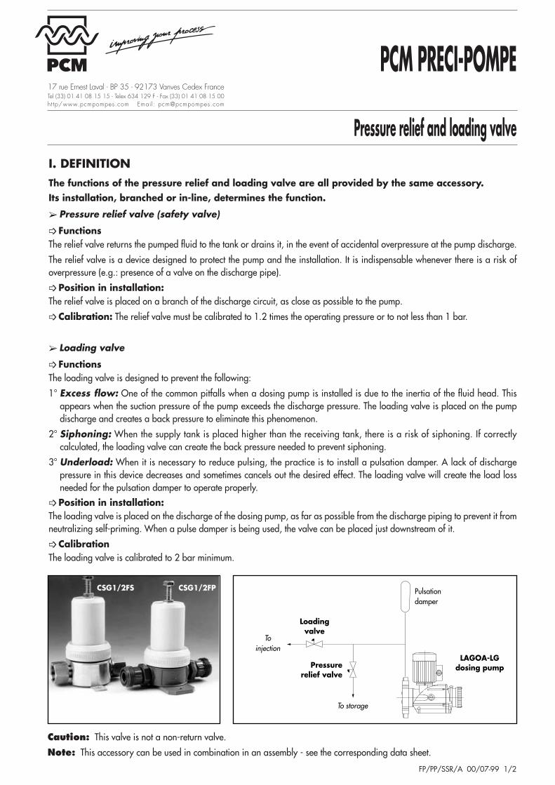
I. DEFINITIONThe functions of the pressure relief and loading valve are all provided by the same accessory.Its installation, branched or in-line, determines the function.
➢ Pressure relief valve (safety valve)
➩ Functions The relief valve returns the pumped fluid to the tank or drains it, in the event of accidental overpressure at the pump discharge.
The relief valve is a device designed to protect the pump and the installation. It is indispensable whenever there is a risk ofoverpressure (e.g.: presence of a valve on the discharge pipe).
➩ Position in installation:The relief valve is placed on a branch of the discharge circuit, as close as possible to the pump.
➩ Calibration: The relief valve must be calibrated to 1.2 times the operating pressure or to not less than 1 bar.
➢ Loading valve
➩ Functions The loading valve is designed to prevent the following:
1° Excess flow: One of the common pitfalls when a dosing pump is installed is due to the inertia of the fluid head. Thisappears when the suction pressure of the pump exceeds the discharge pressure. The loading valve is placed on the pumpdischarge and creates a back pressure to eliminate this phenomenon.
2° Siphoning: When the supply tank is placed higher than the receiving tank, there is a risk of siphoning. If correctlycalculated, the loading valve can create the back pressure needed to prevent siphoning.
3° Underload: When it is necessary to reduce pulsing, the practice is to install a pulsation damper. A lack of dischargepressure in this device decreases and sometimes cancels out the desired effect. The loading valve will create the load lossneeded for the pulsation damper to operate properly.
➩ Position in installation: The loading valve is placed on the discharge of the dosing pump, as far as possible from the discharge piping to prevent it fromneutralizing self-priming. When a pulse damper is being used, the valve can be placed just downstream of it.
➩ Calibration The loading valve is calibrated to 2 bar minimum.
Caution: This valve is not a non-return valve.
Note: This accessory can be used in combination in an assembly - see the corresponding data sheet.
Pulsationdamper
Loadingvalve
Pressurerelief valve
LAGOA-LGdosing pump
To injection
To storage
CSG1/2FS CSG1/2FP
Pressure relief and loading valve
FP/PP/SSR/A 00/07-99 2/2
Flow-rate: 2-4-10 l/h Flow-rate: 9-12 to 35-50l/h Flow-rate: 45-70 to 350 l/h
Code CouplingsCoupling
Code CouplingsCoupling
Code CouplingsCoupling
supplied1/2” Gas
supplied1/2” Gas
supplied1/2” Gas
female female female
PCST4-8P
Flexible hose
CSG1/2FP CST6-12P
Flexible hose
CSG1/2FP CSG1MPGas 1’’
CSG1/2FPPFØ 4x8 Ø 6x12
male*PS
PVC tube for PVC tube forbonding Ø 10x16 bonding Ø 10x16
PC CST6-12PC
Flexible hose
CSG1/2FS CST6-12PC
Flexible hose
CSG1/2FS CSG3/4FSGas 3/4’’
CSG1/2FSØ 6x12 Ø 6x12
femalePVC tube for PVC tube forbonding Ø 10x16 bonding Ø 10x16
HCSG1MP
Gas 1’’CSG1/2FP CSG1MP
Gas 1’’CSG1/2FP CSG1MP
Gas 1’’CSG1/2FP
HD male* male* male*
D CSG1/4FDGas 1/4’’
CSG1/4FDGas 1/4’’
CSG1MDGas 1’’
CSG1/2FDfemale female male*
SCSG1/2FS
Gas 1/2’’CSG1/2FS
Gas 1/2’’CSG3/4FS
Gas 3/4’’CSG1/2FS
SC female female female
* Connection with seal for assembly with nut and idle part (collar) to be bonded or screwed onto pipe.
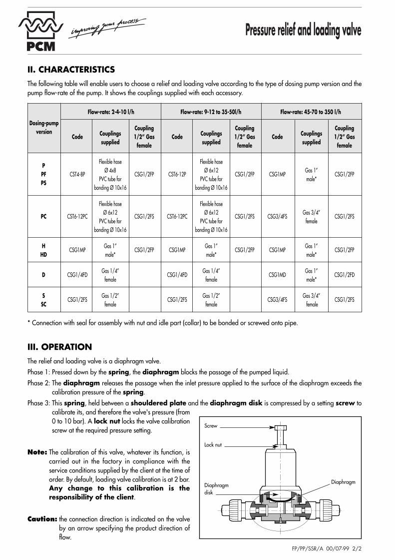
III. OPERATIONThe relief and loading valve is a diaphragm valve.
Phase 1: Pressed down by the spring, the diaphragm blocks the passage of the pumped liquid.
Phase 2: The diaphragm releases the passage when the inlet pressure applied to the surface of the diaphragm exceeds thecalibration pressure of the spring.
Phase 3: This spring, held between a shouldered plate and the diaphragm disk is compressed by a setting screw tocalibrate its, and therefore the valve's pressure (from0 to 10 bar). A lock nut locks the valve calibrationscrew at the required pressure setting.
Note: The calibration of this valve, whatever its function, iscarried out in the factory in compliance with theservice conditions supplied by the client at the time oforder. By default, loading valve calibration is at 2 bar.Any change to this calibration is theresponsibility of the client.
Caution: the connection direction is indicated on the valveby an arrow specifying the product direction offlow.
II. CHARACTERISTICSThe following table will enable users to choose a relief and loading valve according to the type of dosing pump version and thepump flow-rate of the pump. It shows the couplings supplied with each accessory.
Screw
Lock nut
Diaphragmdisk
Diaphragm
Dosing-pumpversion
PCM PRECI-POMPE
Foot valve
FP/PP/CDP/A 00/07-99 1/2
17 rue Ernest Laval - BP 35 - 92173 Vanves Cedex FranceTel (33) 01 41 08 15 15 - Telex 634 129 F - Fax (33) 01 41 08 15 00ht tp/www.pcmpompes.com Emai l : [email protected]
I. DEFINITION
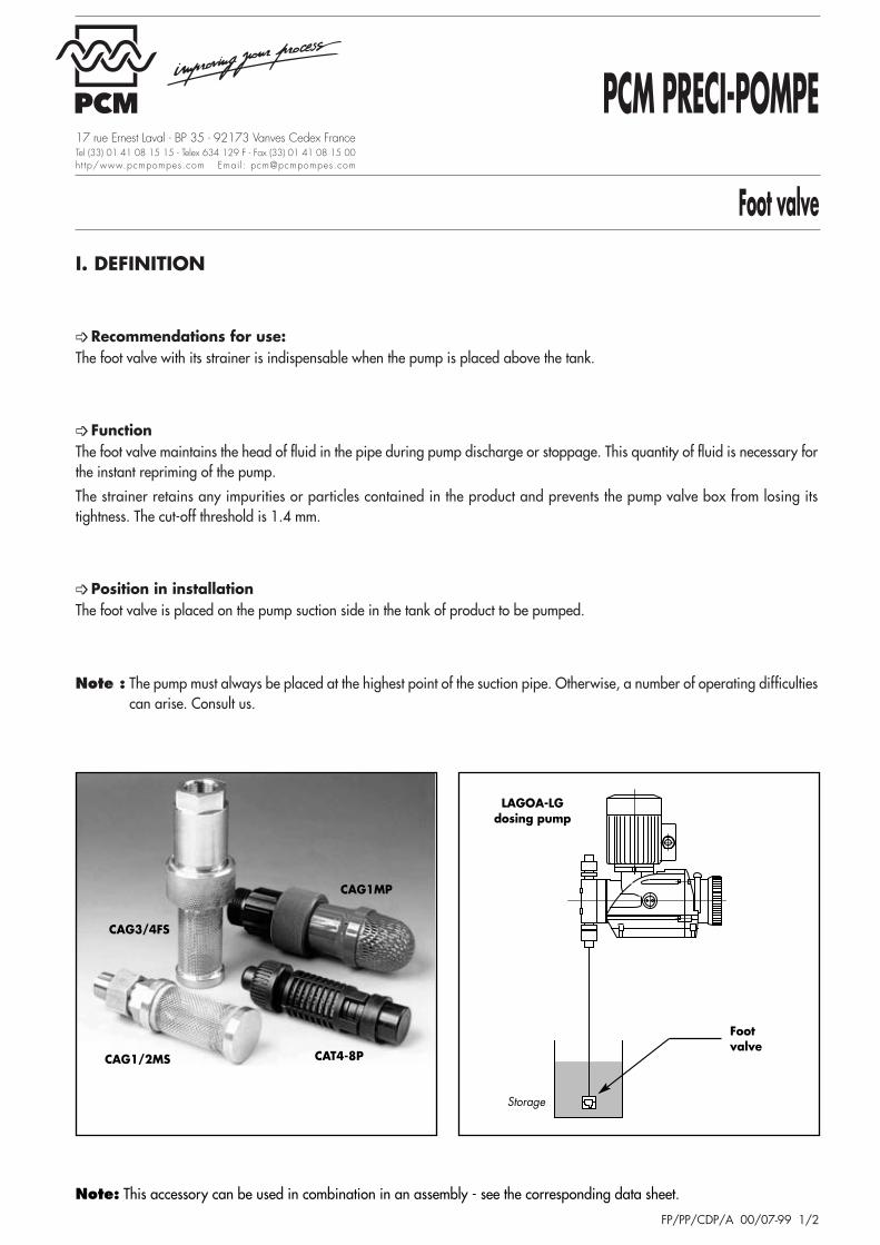
➩ Recommendations for use:The foot valve with its strainer is indispensable when the pump is placed above the tank.
➩ Function The foot valve maintains the head of fluid in the pipe during pump discharge or stoppage. This quantity of fluid is necessary forthe instant repriming of the pump.
The strainer retains any impurities or particles contained in the product and prevents the pump valve box from losing itstightness. The cut-off threshold is 1.4 mm.
➩ Position in installation The foot valve is placed on the pump suction side in the tank of product to be pumped.
Note : The pump must always be placed at the highest point of the suction pipe. Otherwise, a number of operating difficultiescan arise. Consult us.
CAG1/2MS
CAG3/4FS
CAT4-8P
CAG1MP
LAGOA-LGdosing pump
Storage
Footvalve
Note: This accessory can be used in combination in an assembly - see the corresponding data sheet.

Foot valve
FP/PP/CDP/A 00/07-99 2/2
Dosing-pump Flow-rate: 2-4-10 l/h Flow-rate: 9-12 to 35-50 l/h Flow-rate: 45-70 to 350 l/h
versionCode Couplings supplied Code Couplings supplied Code Couplings supplied
P CAT4-8PFlexible hose Ø 4x8
CAT6-12PFlexible hose Ø 6x12
CAG1MPGas 1’’ male*PF CAT4-8PF
PVC pipe for bonding Ø 10x16CAT6-12PF
PVC pipe for bonding Ø 10x16CAG1MPF
PS CAT4-8PS CAT6-12PS CAG1MPS
PC CAT6-12PCFlexible hose Ø 6x12
CAT6-12PCFlexible hose Ø 6x12
CAG3/4PC Gas 3/4’’ femalePVC pipe for bonding Ø 10x16 PVC pipe for bonding Ø 10x16
HCAG1M1HD Gas 1’’ male* CAG1M1HD Gas 1’’ male CAG1M2HD Gas 1’’ male*
HD
D CAG1/4FD Gas 1/4’’ female CAG1/4FD Gas 1/4’’ female CAG1MD Gas 1’’ male*
S-SC CAG1/2MS Gas 1/2’’ male CAG1/2MS Gas 1/2’’ male CAG3/4FS Gas 3/4’’ female
* Connection with seal for nut and idle part assembly (collar) for bonding or screwing onto pipe.
III. OPERATION
➩ Suction The pumped fluid passes through a filter cartridge, liftingthe ball off the seat (guided by a ball guide) so that thefluid is allowed to flow towards the pumping head.
➩ Discharge The head of fluid included between the foot valve and thepump suction valve box is maintained in the pipe becausetightness is ensured by the ball pressing on the seat.
Caution : The foot valve with its strainer must always beinstalled vertically because the ball descends ontothe seat by gravity.
II. CHARACTERISTICSThe following table enables users to choose a foot valve according to the type of dosing pump version and the pump flow-rate.It shows the couplings supplied with each accessory.
Ball guide
Seat
Filtercartridge
Ball
Pumpedfluid
PCM PRECI-POMPE
4-function valve
FP/PP/S4F/A 00/07-99 1/2
17 rue Ernest Laval - BP 35 - 92173 Vanves Cedex FranceTel (33) 01 41 08 15 15 - Telex 634 129 F - Fax (33) 01 41 08 15 00ht tp/www.pcmpompes.com Emai l : [email protected]
I. DEFINITION
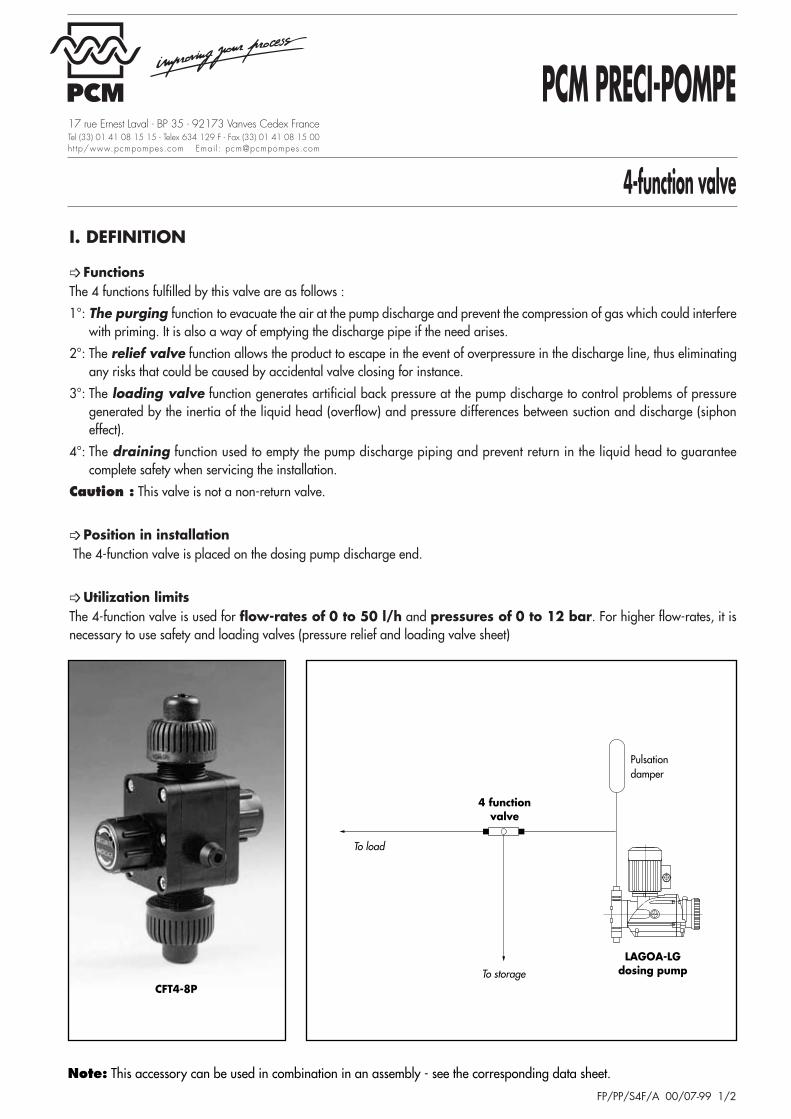
➩ Functions The 4 functions fulfilled by this valve are as follows :
1°: The purging function to evacuate the air at the pump discharge and prevent the compression of gas which could interferewith priming. It is also a way of emptying the discharge pipe if the need arises.
2°: The relief valve function allows the product to escape in the event of overpressure in the discharge line, thus eliminatingany risks that could be caused by accidental valve closing for instance.
3°: The loading valve function generates artificial back pressure at the pump discharge to control problems of pressuregenerated by the inertia of the liquid head (overflow) and pressure differences between suction and discharge (siphoneffect).
4°: The draining function used to empty the pump discharge piping and prevent return in the liquid head to guaranteecomplete safety when servicing the installation.
Caution : This valve is not a non-return valve.
➩ Position in installation The 4-function valve is placed on the dosing pump discharge end.
➩ Utilization limits The 4-function valve is used for flow-rates of 0 to 50 l/h and pressures of 0 to 12 bar. For higher flow-rates, it isnecessary to use safety and loading valves (pressure relief and loading valve sheet)
CFT4-8P
Pulsationdamper
LAGOA-LGdosing pumpTo storage
To load
4 functionvalve
Note: This accessory can be used in combination in an assembly - see the corresponding data sheet.

4-function valve
FP/PP/S4F/A 00/07-99 2/2
Dosing-pump Flow-rate: 2-4-10 l/h Flow-rate: 9-12 to 35-50 l/h
version Code Couplings supplied Code Couplings supplied
P CFT4-8PFlexible hose Ø 4x8
CFT6-12PFlexible hose Ø 6x12
PVC pipe for bonding Ø 10x16 PVC pipe for bonding Ø 10x16
PF CFT4-8PFFlexible hose Ø 4x8
CFT6-12PFFlexible hose Ø 6x12
PVC pipe for bonding Ø 10x16 PVC pipe for bonding Ø 10x16
PS CFT4-8PSFlexible hose Ø 4x8
CFT6-12PSFlexible hose Ø 6x12
PVC pipe for bonding Ø 10x16 PVC pipe for bonding Ø 10x16
III. OPERATION
➩ Priming purge Phase 1: Unscrew thumbwheel 1.
Phase 2: The removal of the diaphragm opens the passage from the conduit to the outlet (tank or drain), so that the gasor compressed liquid on the pump discharge can be evacuated.
Phase 3: Screw down thumbwheel 1.
➩ Safety valve Phase 1: Screw thumbwheel 1 to the stop.
Phase 2: The compression of the spring will press thediaphragm against the conduit.
Phase 3: The safety valve calibration pressure is factoryadjusted to the pressure needed to open theconduit.
Phase 4: In the event of overpressure, the pumped liquid willescape towards storage via the outlet.
➩ Loading valvePhase 1: Screw thumbwheel 2 to the stop.
Phase 2: The spring is compressed on the diaphragm withcalibration of 1.5 bar ± 0.5 bar.
Phase 3: The pump liquid will be exposed at the least tothe calibration pressure. This back pressure willeliminate any risks of overflow and siphoning.
➩ Draining Phase 1: Unscrew thumbwheels 1 and 2.
Phase 2: The discharge column will be evacuated via theoutlet towards the storage.
Phase 3: Screw down thumbwheels 1 and 2.
II. CHARACTERISTICSThe following table enables users to choose a 4-function valve according to the type of dosing pump version and the pump flow-rate. It shows the couplings supplied with each accessory.
Note : This valve is calibrated in the plant in compliance with the service conditions communicated by the customer at the timeof order. By default, calibration is 2 bar for the loading valve function.Any change in calibration will be on the customer’s responsibility.
Diaphragm
Thumbwheel 2
Spring
Diaphragm
Thumbwheel 1
Spring
PCM PRECI-POMPE
Pulsation damper
FP/PP/ADP/A 00/07-99 1/2
17 rue Ernest Laval - BP 35 - 92173 Vanves Cedex FranceTel (33) 01 41 08 15 15 - Telex 634 129 F - Fax (33) 01 41 08 15 00ht tp/www.pcmpompes.com Emai l : [email protected]
I. DEFINITION
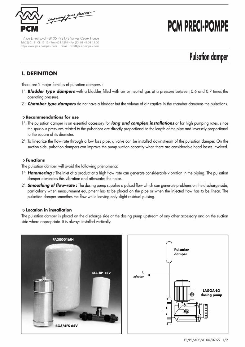
There are 2 major families of pulsation dampers :
1°: Bladder type dampers with a bladder filled with air or neutral gas at a pressure between 0.6 and 0.7 times theoperating pressure.
2°: Chamber type dampers do not have a bladder but the volume of air captive in the chamber dampens the pulsations.
➩ Recommendations for use 1°: The pulsation damper is an essential accessory for long and complex installations or for high pumping rates, since
the spurious pressures related to the pulsations are directly proportional to the length of the pipe and inversely proportionalto the square of its diameter.
2°: To linearize the flow-rate through a low loss pipe, a valve can be installed downstream of the pulsation damper. On thesuction side, pulsation dampers can improve the pump suction capacity when there are considerable head losses involved.
➩ Functions The pulsation damper will avoid the following phenomena:
1°: Hammering : The inlet of a product at a high flow-rate can generate considerable vibration in the piping. The pulsationdamper eliminates this vibration and attenuates the noise.
2°: Smoothing of flow-rate : The dosing pump supplies a pulsed flow which can generate problems on the discharge side,particularly when measurement equipment has to be placed on the pipe or when the injected flow has to be linear. Thepulsation damper smoothes the flow while leaving only slight residual pulsing.
➩ Location in installation The pulsation damper is placed on the discharge side of the dosing pump upstream of any other accessory and on the suctionside where appropriate. It is always installed vertically.
BG3/4FS 65V
BT4-8P 15V
PA300G1MH
Pulsationdamper
LAGOA-LGdosing pump
Toinjection
Pulsation damper
FP/PP/ADP/A 00/07-99 2/2
Flow-rate: 2-4-10 l/h Flow-rate: 9-12 to 35-50l/h Flow-rate: 45-70 to 350 l/h
Code Couplings Code CodeCouplings
Couplings CodeCouplings
Couplingswith 1/2” Gas without with
supplied1/2” Gas with
supplied3/4” Gas
couplings female couplings couplings female couplings female
P**BT4-8P15E
Flexible hose Ø 4x8BG1/2FP15E BT6-12P15E
Flexible hose Ø 6x12BG1/2FP15E BG1MP65E Gas 1’’ BG3/4FP65E
PFBT4-8P15V
PVC tube for BG1/2FP15V BT6-12P15V
PVC tube for BG1/2FP15V BG1MP65V male* BG3/4FP65V
PS bonding Ø 10x16 bonding Ø 10x16
Flexible hose Ø 6x12 Flexible hose Ø 6x12Gas 3/4’’
PC** BT6-12PC15V PVC tube for BG1/2FS15V BT6-12PC15V PVC tube for BG1/2FS15V BG3/4FS65Vfemale
BG3/4FS65Vbonding Ø 10x16 bonding Ø 10x16
S BG1/2FS15E Gas 1/2’’ BG1/2FS15E Gas 1/2’’ BG3/4FS65E Gas 3/4’’SC BG1/2FS15V female BG1/2FS15V female BG3/4FS65V female
2 4-10 9-25 12-35 20-50 45-110 70-170 100-260 140 350
Chamber code PA15 PA50 PA50 PA100
PA50
PA200
PA200
PA300 PA400 PA300P<5 b P<6 b
PA100 PA300P>5 b P>6 b
Coupling Gas 3/8’’ male = Code G3/8MH Gas 1’’ male = Code G1MH
* Connection with seal for assembly with nut and idle part (collar) for bonding or screwing onto pipe.** The dampers are available with standard 1/2" or 3/4" Gas female coupling or with couplings identical to those of pump.
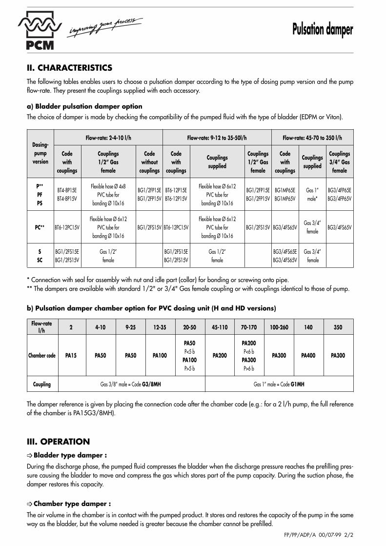
b) Pulsation damper chamber option for PVC dosing unit (H and HD versions)
II. CHARACTERISTICSThe following tables enables users to choose a pulsation damper according to the type of dosing pump version and the pumpflow-rate. They present the couplings supplied with each accessory.
a) Bladder pulsation damper optionThe choice of damper is made by checking the compatibility of the pumped fluid with the type of bladder (EDPM or Viton).
The damper reference is given by placing the connection code after the chamber code (e.g.: for a 2 l/h pump, the full referenceof the chamber is PA15G3/8MH).
III. OPERATION➩ Bladder type damper :
During the discharge phase, the pumped fluid compresses the bladder when the discharge pressure reaches the prefilling pres-sure causing the bladder to move and compress the gas which stores part of the pump capacity. During the suction phase, thedamper restores this capacity.
➩ Chamber type damper :
The air volume in the chamber is in contact with the pumped product. It stores and restores the capacity of the pump in the sameway as the bladder, but the volume needed is greater because the chamber cannot be prefilled.
Dosing-pump
version
Flow-rate l/h
PCM PRECI-POMPE
Injection quill
FP/PE/CDI/A 00/07-99 1/2
17 rue Ernest Laval - BP 35 - 92173 Vanves Cedex FranceTel (33) 01 41 08 15 15 - Telex 634 129 F - Fax (33) 01 41 08 15 00ht tp/www.pcmpompes.com Emai l : [email protected]
I. DEFINITION
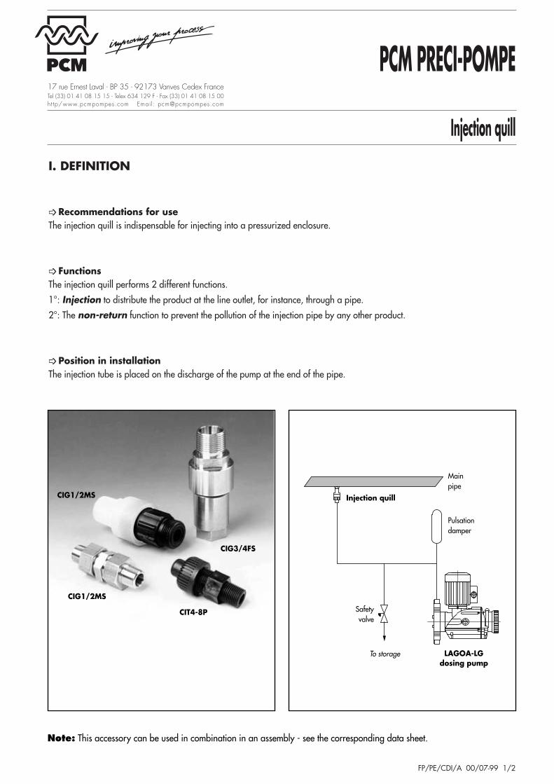
➩ Recommendations for use The injection quill is indispensable for injecting into a pressurized enclosure.
➩ Functions The injection quill performs 2 different functions.
1°: Injection to distribute the product at the line outlet, for instance, through a pipe.
2°: The non-return function to prevent the pollution of the injection pipe by any other product.
➩ Position in installation The injection tube is placed on the discharge of the pump at the end of the pipe.
CIG1/2MS
CIG1/2MS
CIT4-8P
CIG3/4FS
Mainpipe
Pulsationdamper
LAGOA-LGdosing pump
To storage
Safetyvalve
Injection quill
Note: This accessory can be used in combination in an assembly - see the corresponding data sheet.

Injection quill
FP/PE/CDI/A 00/07-99 2/2
Connection with seal for nut and idle part assembly (collar) for bonding or screwing onto the pipe.
III. OPERATIONNote :
a) All the injection valves are calibrated to 0.8 bar ± 0.2 bar.
b) For all the versions, the coupling at the injection point is 1/2’’ tapered male gas pitch for flow-rates of 2 to 35 and 50 l/hand 1’’ tapered male gas pitch for flow-rates of 45 and 70 to 350 l/h.
➩ Injection Phase 1 : The pumped fluid pushes the ball to compress the
spring, lifting it off its seat and allowing thefluid to flow towards the injection point.
➩ Non-return Phase 2 : Because of its loading, the spring brings the ball
back onto the seat to ensure tightness. The returnof the ball onto the seat is favored by thepressure in the enclosure into which the product isinjected.
II. CHARACTERISTICSThe following table enables users to choose a injection quill according to the type of dosing pump version and the pumpflow-rate. It shows the couplings supplied with each accessory.
Dosing-pump Flow-rate: 2-4-10 l/h Flow-rate: 9-12 to 35-50 l/h Flow-rate: 45-70 to 350 l/h
versionCode Couplings supplied Code Couplings supplied Code Couplings supplied
P CIT4-8PFlexible hose Ø 4x8
CIT6-12PFlexible hose Ø 6x12
CIG1MPGas 1’’ male*PF CIT4-8PF
PVC pipe for bonding Ø 10x16CIT6-12PF
PVC pipe for bonding Ø 10x16CIG1MPF
PS CIT4-8PS CIT6-12PS CIG1MPS
PC CIT6-12PCFlexible hose Ø 4x8 CIT6-12PC Flexible hose Ø 4x8
CIG3/4FS Gas 3/4’’ femalePVC pipe for bonding Ø 10x16 PVC pipe for bonding Ø 10x16
HCIG1M1H Gas 1’’ male* CIG1M1H Gas 1’’ male CIG1M2H Gas 1’’ male*
HD
S-SC CIG1/2MS Gas 1/2’’ male CIG1/2MS Gas 1/2’’ male CIG3/4FS Gas 3/4’’ female
Seat
Ball
Spring
Pumpedfluid
PCM PRECI-POMPE
Flooded suction pump system
FP/PP/PECHA/A 00/07-99 1/2
17 rue Ernest Laval - BP 35 - 92173 Vanves Cedex FranceTel (33) 01 41 08 15 15 - Telex 634 129 F - Fax (33) 01 41 08 15 00ht tp/www.pcmpompes.com Emai l : [email protected]
I. DEFINITION
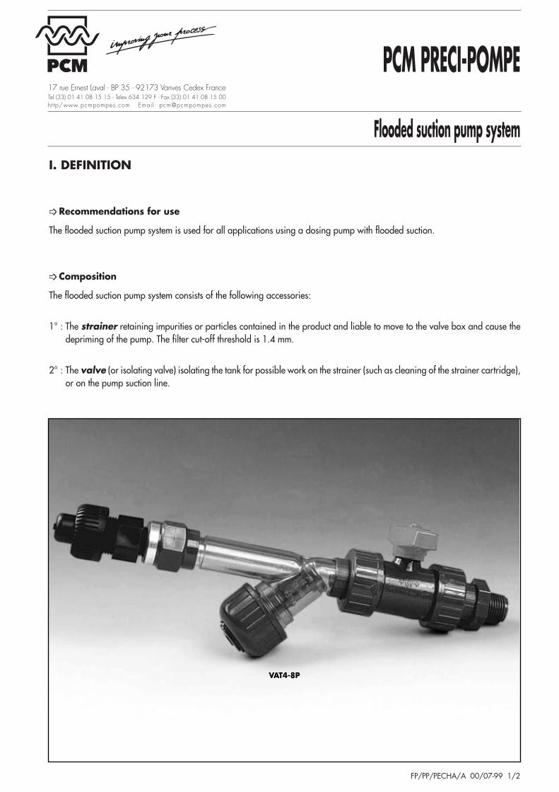
➩ Recommendations for use
The flooded suction pump system is used for all applications using a dosing pump with flooded suction.
➩ Composition
The flooded suction pump system consists of the following accessories:
1° : The strainer retaining impurities or particles contained in the product and liable to move to the valve box and cause thedepriming of the pump. The filter cut-off threshold is 1.4 mm.
2° : The valve (or isolating valve) isolating the tank for possible work on the strainer (such as cleaning of the strainer cartridge),or on the pump suction line.
VAT4-8P
Flooded suction pump system
FP/PP/PECHA/A 00/07-99 2/2
* Connection with seal for assembly with nut and idle part (collar) for bonding or screwing onto pipe.
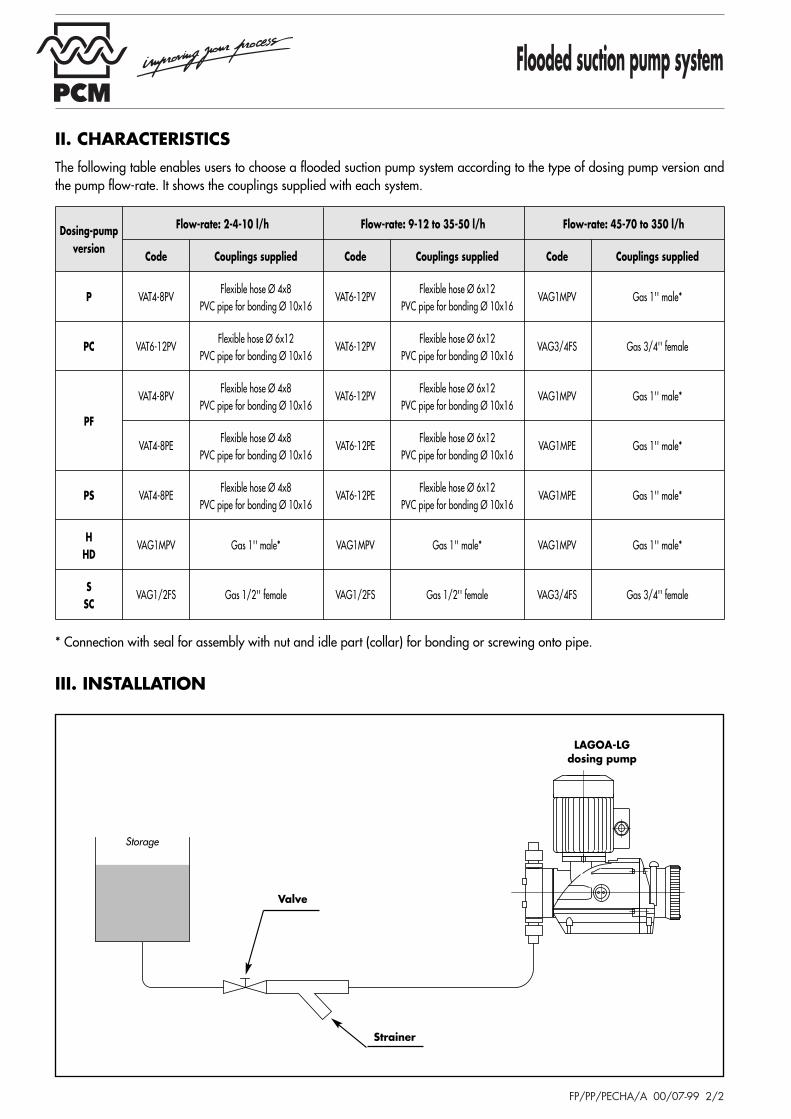
III. INSTALLATION
II. CHARACTERISTICSThe following table enables users to choose a flooded suction pump system according to the type of dosing pump version andthe pump flow-rate. It shows the couplings supplied with each system.
Storage
Strainer
Valve
LAGOA-LGdosing pump
Dosing-pump Flow-rate: 2-4-10 l/h Flow-rate: 9-12 to 35-50 l/h Flow-rate: 45-70 to 350 l/h
versionCode Couplings supplied Code Couplings supplied Code Couplings supplied
P VAT4-8PVFlexible hose Ø 4x8
VAT6-12PVFlexible hose Ø 6x12
VAG1MPV Gas 1'' male*PVC pipe for bonding Ø 10x16 PVC pipe for bonding Ø 10x16
PC VAT6-12PVFlexible hose Ø 6x12
VAT6-12PVFlexible hose Ø 6x12
VAG3/4FS Gas 3/4'' femalePVC pipe for bonding Ø 10x16 PVC pipe for bonding Ø 10x16
PF
VAT4-8PVFlexible hose Ø 4x8
VAT6-12PVFlexible hose Ø 6x12
VAG1MPV Gas 1'' male*PVC pipe for bonding Ø 10x16 PVC pipe for bonding Ø 10x16
VAT4-8PEFlexible hose Ø 4x8
VAT6-12PEFlexible hose Ø 6x12
VAG1MPE Gas 1'' male*PVC pipe for bonding Ø 10x16 PVC pipe for bonding Ø 10x16
PS VAT4-8PEFlexible hose Ø 4x8
VAT6-12PEFlexible hose Ø 6x12
VAG1MPE Gas 1'' male*PVC pipe for bonding Ø 10x16 PVC pipe for bonding Ø 10x16
HVAG1MPV Gas 1'' male* VAG1MPV Gas 1'' male* VAG1MPV Gas 1'' male*
HD
SVAG1/2FS Gas 1/2'' female VAG1/2FS Gas 1/2'' female VAG3/4FS Gas 3/4'' female
SC
PCM PRECI-POMPE
Flooded suction ready-to-dose system
FP/PP/PADCHA/A 00/07-99 1/2
17 rue Ernest Laval - BP 35 - 92173 Vanves Cedex FranceTel (33) 01 41 08 15 15 - Telex 634 129 F - Fax (33) 01 41 08 15 00ht tp/www.pcmpompes.com Emai l : [email protected]
I. DEFINITION
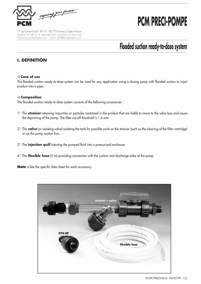
➩ Case of use The flooded suction ready-to-dose system can be used for any application using a dosing pump with flooded suction to injectproduct into a pipe.
➩ Composition The flooded suction ready-to-dose system consists of the following accessories :
1°: The strainer retaining impurities or particles contained in the product that are liable to move to the valve box and causethe depriming of the pump. The filter cut-off threshold is 1.4 mm.
2°: The valve (or isolating valve) isolating the tank for possible work on the strainer (such as the cleaning of the filter cartridge)or on the pump suction line.
3°: The injection quill injecting the pumped fluid into a pressurized enclosure.
4°: The flexible hose (5 m) providing connection with the suction and discharge sides of the pump.
Note : See the specific data sheet for each accessory.
Flexible hose
CIT4-8P
strainer + valve
Flooded suction ready-to-dose system
FP/PP/PADCHA/A 00/07-99 2/2
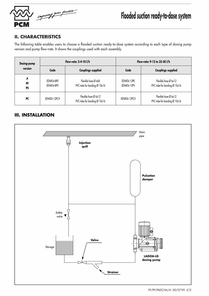
II. CHARACTERISTICSThe following table enables users to choose a flooded suction ready-to-dose system according to each type of dosing pumpversion and pump flow-rate. It shows the couplings used with each assembly.
III. INSTALLATION
Storage
Injectionquill
Mainpipe
Pulsationdamper
Safetyvalve
LAGOA-LGdosing pump
Strainer
Valve
Dosing-pump Flow-rate: 2-4-10 l/h Flow-rate: 9-12 to 35-50 l/h
version Code Couplings supplied Code Couplings supplied
PEDVAT4-8PE Flexible hose Ø 4x8 EDVAT6-12PE Flexible hose Ø 6x12
PFEDVAT4-8PV PVC tube for bonding Ø 10x16 EDVAT6-12PV PVC tube for bonding Ø 10x16
PS
PC EDVAT6-12PCVFlexible hose Ø 6x12
EDVAT6-12PCVFlexible hose Ø 6x12
PVC tube for bonding Ø 10x16 PVC tube for bonding Ø 10x16
PCM PRECI-POMPE
Suction lift ready-to-dose system
FP/PP/PADASP/A 00/07-99 1/2
17 rue Ernest Laval - BP 35 - 92173 Vanves Cedex FranceTel (33) 01 41 08 15 15 - Telex 634 129 F - Fax (33) 01 41 08 15 00ht tp/www.pcmpompes.com Emai l : [email protected]
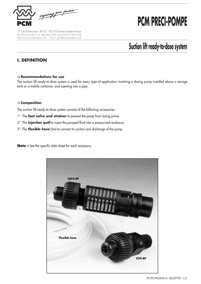
I. DEFINITION
➩ Recommendations for use The suction lift ready-to-dose system is used for every type of application involving a dosing pump installed above a storagetank or a mobile container, and injecting into a pipe.
➩ Composition
The suction lift ready-to-dose system consists of the following accessories :
1°: The foot valve and strainer to prevent the pump from losing prime.
2°: The injection quill to inject the pumped fluid into a pressurized enclosure.
3°: The flexible hose (5m) to connect to suction and discharge of the pump.
Note : See the specific data sheet for each accessory.
Flexible hose
CAT4-8P
CIT4-8P
Suction lift ready-to-dose system
FP/PP/PADASP/A 00/07-99 2/2
* Connection with seal for assembly of nut and idle part (collar) to be bonded or screwed onto the pipe.
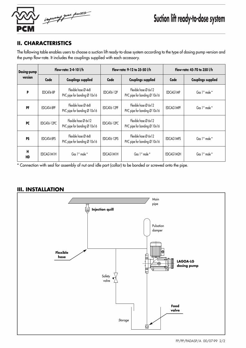
III. INSTALLATION
II. CHARACTERISTICSThe following table enables users to choose a suction lift ready-to-dose system according to the type of dosing pump version andthe pump flow-rate. It includes the couplings supplied with each accessory.
Storage
Injection quill
Flexiblehose
Mainpipe
Foodvalve
Pulsationdamper
Safetyvalve
LAGOA-LGdosing pump
Dosing-pump Flow-rate: 2-4-10 l/h Flow-rate: 9-12 to 35-50 l/h Flow-rate: 45-70 to 350 l/h
versionCode Couplings supplied Code Couplings supplied Code Couplings supplied
P EDCAT4-8PFlexible hose Ø 4x8
EDCAT6-12PFlexible hose Ø 6x12
EDCAG1MP Gas 1'' male *PVC pipe for bonding Ø 10x16 PVC pipe for bonding Ø 10x16
PF EDCAT4-8PFFlexible hose Ø 4x8
EDCAT6-12PFFlexible hose Ø 6x12
EDCAG1MPF Gas 1'' male *PVC pipe for bonding Ø 10x16 PVC pipe for bonding Ø 10x16
PC EDCAT6-12PCFlexible hose Ø 6x12
EDCAT6-12PCFlexible hose Ø 6x12
PVC pipe for bonding Ø 10x16 PVC pipe for bonding Ø 10x16
PS EDCAT4-8PSFlexible hose Ø 4x8
EDCAT6-12PSFlexible hose Ø 6x12
EDCAG1MPS Gas 1'' male *PVC pipe for bonding Ø 10x16 PVC pipe for bonding Ø 10x16
HEDCAG1M1H Gas 1'' male * EDCAG1M1H Gas 1'' male * EDCAG1M2H Gas 1'' male *
HD
PCM PRECI-POMPE
Pulsation damper assembly
FP/PP/EADP/A 00/07-99 1/2
17 rue Ernest Laval - BP 35 - 92173 Vanves Cedex FranceTel (33) 01 41 08 15 15 - Telex 634 129 F - Fax (33) 01 41 08 15 00ht tp/www.pcmpompes.com Emai l : [email protected]
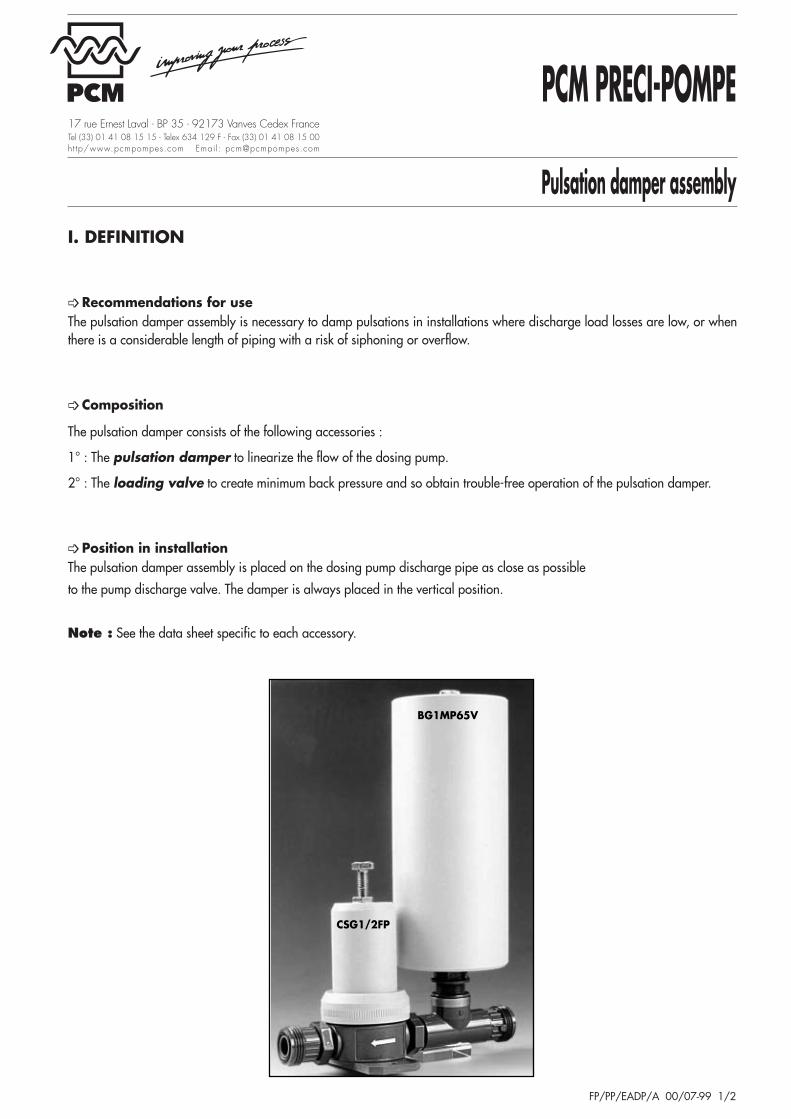
I. DEFINITION
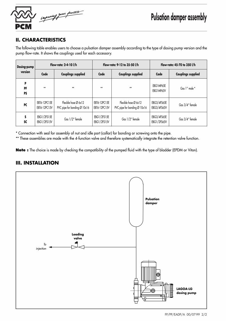
➩ Recommendations for use The pulsation damper assembly is necessary to damp pulsations in installations where discharge load losses are low, or whenthere is a considerable length of piping with a risk of siphoning or overflow.
➩ Composition
The pulsation damper consists of the following accessories :
1° : The pulsation damper to linearize the flow of the dosing pump.
2° : The loading valve to create minimum back pressure and so obtain trouble-free operation of the pulsation damper.
➩ Position in installation The pulsation damper assembly is placed on the dosing pump discharge pipe as close as possible
to the pump discharge valve. The damper is always placed in the vertical position.
Note : See the data sheet specific to each accessory.
BG1MP65V
CSG1/2FP
Pulsation damper assembly
FP/PP/EADP/A 00/07-99 2/2
* Connection with seal for assembly of nut and idle part (collar) for bonding or screwing onto the pipe.** These assemblies are made with the 4-function valve and therefore systematically integrate the retention valve function.
Note : The choice is made by checking the compatibility of the pumped fluid with the type of bladder (EPDM or Viton).
III. INSTALLATION
II. CHARACTERISTICSThe following table enables users to choose a pulsation damper assembly according to the type of dosing pump version and thepump flow-rate. It shows the couplings used for each accessory.
Toinjection
Pulsation damper
Loadingvalve
LAGOA-LGdosing pump
Dosing-pump Flow-rate: 2-4-10 l/h Flow-rate: 9-12 to 35-50 l/h Flow-rate: 45-70 to 350 l/h
versionCode Couplings supplied Code Couplings supplied Code Couplings supplied
P** ** ** **
EBG1MP65EGas 1'' male *PF
EBG1MP65VPS
PCEBT6-12PC15E Flexible hose Ø 6x12 EBT6-12PC15E Flexible hose Ø 6x12 EBG3/4FS65E
Gas 3/4'' femaleEBT6-12PC15V PVC pipe for bonding Ø 10x16 EBT6-12PC15V PVC pipe for bonding Ø 10x16 EBG3/4FS65V
S EBG1/2FS15EGas 1/2'' female
EBG1/2FS15EGas 1/2'' female
EBG3/4FS65EGas 3/4'' female
SC EBG1/2FS15V EBG1/2FS15V EBG1/2FS65V
PCM PRECI-POMPE
Pulsation damper with pressure relief valve system
FP/PP/EADPSE/A 00/07-99 1/2
17 rue Ernest Laval - BP 35 - 92173 Vanves Cedex FranceTel (33) 01 41 08 15 15 - Telex 634 129 F - Fax (33) 01 41 08 15 00ht tp/www.pcmpompes.com Emai l : [email protected]
I. DEFINITION
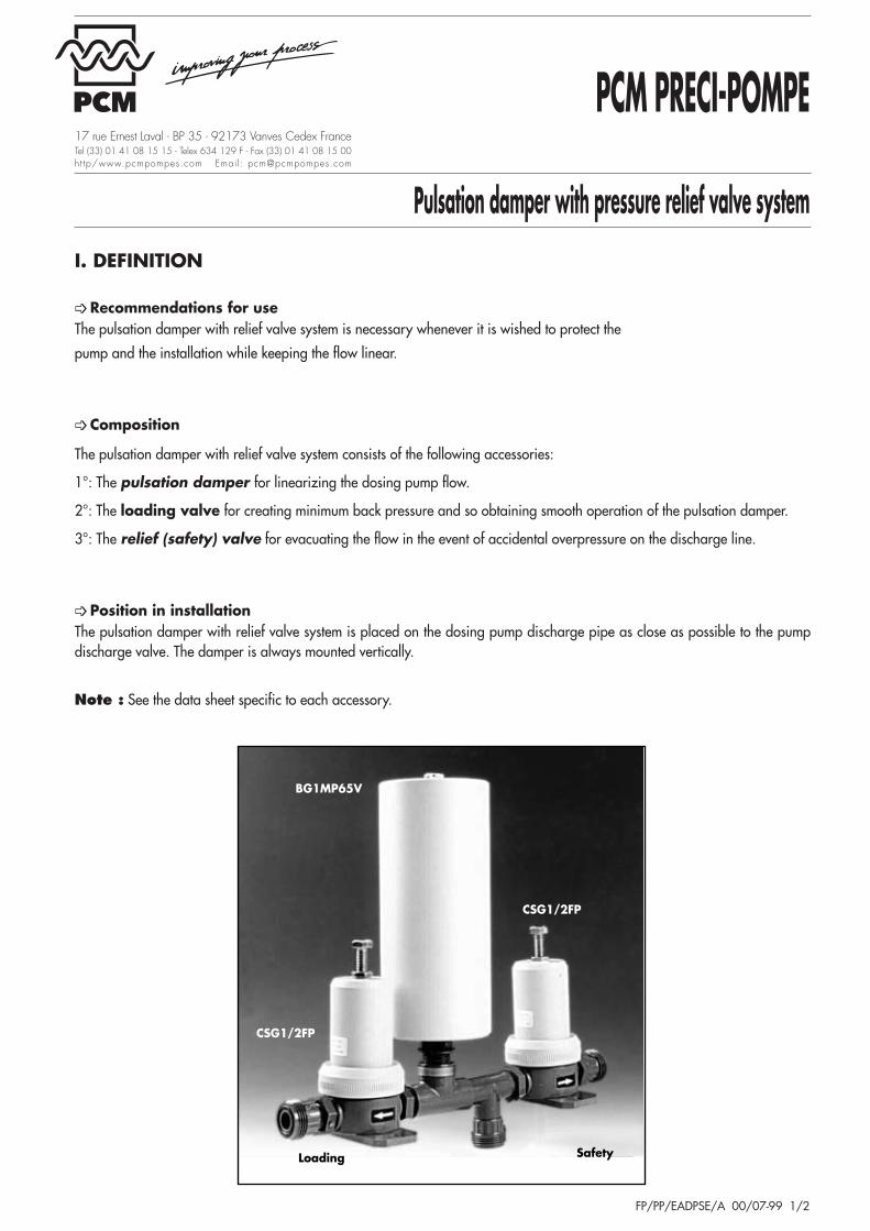
➩ Recommendations for use The pulsation damper with relief valve system is necessary whenever it is wished to protect the
pump and the installation while keeping the flow linear.
➩ Composition
The pulsation damper with relief valve system consists of the following accessories:
1°: The pulsation damper for linearizing the dosing pump flow.
2°: The loading valve for creating minimum back pressure and so obtaining smooth operation of the pulsation damper.
3°: The relief (safety) valve for evacuating the flow in the event of accidental overpressure on the discharge line.
➩ Position in installation The pulsation damper with relief valve system is placed on the dosing pump discharge pipe as close as possible to the pumpdischarge valve. The damper is always mounted vertically.
Note : See the data sheet specific to each accessory.
CSG1/2FP
CSG1/2FP
Loading Safety
BG1MP65V

Pulsation damper with pressure relief valve system
FP/PP/EADPSE/A 00/07-99 2/2
* Coupling with seal for assembly of nut and idle part (collar) for bonding or screwing onto pipe.
Note : The choice of system is made by checking the compatibility of the pumped fluid with the type of bladder (EPDM or Viton).
III. INSTALLATION
II. CHARACTERISTICSThe following table enables users to choose a pulsation damper with pressure relief valve system according to the type of dosingpump version and the pump flow-rate. It shows the couplings supplied with each assembly.
Toinjection
To storage
Loadingvalve
Pulsationdamper
Safetyvalve
LAGOA-LGdosing pump
Dosing-pump Flow-rate: 2-4-10 l/h Flow-rate: 9-12 to 35-50 l/h Flow-rate: 45-70 to 350 l/h
versionCode Couplings supplied Code Couplings supplied Code Couplings supplied
PEBFT4-8P15E Flexible hose Ø 4x8 EBFT6-12PC15E Flexible hose Ø 6x12 EBSG1MP65E
Gas 1'' male *PFEBFT4-8P15V PVC pipe for bonding Ø 10x16 EBFT6-12PC15V PVC pipe for bonding Ø 10x16 EBSG1MP65V
PS
PCEBFT6-12PC15E Flexible hose Ø 4x8 EBFT6-12PC15E Flexible hose Ø 6x12 EBSG3/4FS65E
Gas 3/4''maleEBFT6-12PC15V PVC pipe for bonding Ø 10x16 EBFT6-12PC15V PVC pipe for bonding Ø 10x16 EBSG3/4FS65V
S EBSG1/2FS15EGas 1/2'' female
EBSG1/2FS15EGas 1/2'' female
EBSG3/4FS65EGas 3/4'' female
SC EBSG1/2FS15V EBSG1/2FS15V EBSG3/4FS65V

I. DEFINITION
➩ Applications The DOSUNITs are designed to dose most of the reagents used for water treatment or in every other activity sector. However,the product must be compatible with polyethylene (see corrosion table) and the density should not exceed 1.3 at 30°C.
➩ Composition The DOSUNIT is a dosing unit for the preparation of a reagent with or without a mixer.
Tanks for DOSUNIT, of food grade, are made of polyethylene.
They are supplied as standard with a screw-on lid and can be configured in two forms:
a) Dosunit with tank for suction lift pump (BA) comprising :
• A tank with a pump support plate and a drain valve
• A LAGOA-LG dosing pump
• A suction lift ready-to-dose system consisting of: a foot valve, 5 m of flexible hose and aninjection quill.
b) Dosunit with tank for flooded suction pump (BV) comprising :
• A tank with a single vent
• A LAGOA-LG dosing pump
• A flooded suction ready-to-dose system consisting of : a flooded suctionpump system, 5 m of flexible hose and an injection quill.
Note : See data sheet specific to each accessory or assembly.
A number of the options and accessories may be combined with each of these assemblies :
PCM PRECI-POMPE
DOSUNIT
FP/PP/DOSUNIT/A 00/07-99 1/2
17 rue Ernest Laval - BP 35 - 92173 Vanves Cedex FranceTel (33) 01 41 08 15 15 - Telex 634 129 F - Fax (33) 01 41 08 15 00ht tp/www.pcmpompes.com Emai l : [email protected]

DOSUNIT
FP/PP/DOSUNIT/A 00/07-99 2/2
Tank volume (I) CODE MIXER FlexibleThickness Electric
Manualhose
Max. load Suction LoadCode Power (kW) Speed (rpm) Version protection kit
BA12 BV12
E150S12 0,25 1500 Stainless
M/00/12 KTP12120 l E75S12 0,18 750 Stainless4 mm E50S12 0,25 101 Stainless25 kg E150P12 0,25 1500 Polypro
E755P12 0,18 750 Polypro
250 lBA25 BV25
E42S25 0,25 420 Stainless4 mm
E150S25 0,25 1500 Stainless25 kg E75S25 0,18 750 Stainless M/00/25 KTP25500 l E150P25 0,25 1500 Polypro5 mm E75P25 0,18 750 Polypro40 kg
BA50 BV50E34S50 0,25 340 Stainless
1000 l BA100 BV100
E150S100 0,25 1500 Stainless
KTP100E75S100 0,18 750 StainlessE28S100 0,25 280 StainlessE150P100 0,25 1500 PolyproE75P100 0,18 750 Polypro
Note : For a 250 l tank, the corresponding electric stirrer is E42S25 and for a 500 l tank, E34S50. The other stirrersare common to the 250 and 500 l tanks.
III. DIMENSIONSThe dimensional drawings of the DOSUNITs are available for all configurations (flooded suction or suction lift) promptly onrequest.
➢ Options- Floor mounting kit (/ FS) Four brackets to anchor the tank - Single vent (/ ES) Eliminates negative pressure inside the tank - Neutralization vent (/EN) Eliminates negative pressure and routes the stored product vapors towards a
neutralization device.- Production identification plate (/ I)- Accessory support bracket (/ S)- Lid lock (/ L)
➢ Accessories- High level detector (/NH) Indicates full tank - Low level detector (/NB) Indicates empty tank - Manual or electric mixers Of polypropylene or stainless steel depending on type of product, brings the product
into solution from crystallized or flake form - Flexible hose protection kit Prevents suction tube from winding around stirrer (necessary for suction pumping).
Note : The codes of each accessory or option are given in parentheses.
➩ Installation conditionsThe DOSUNITs are anti-UV treated and can be left outdoors without any risk of deterioration. Installing a single vent orneutralizer is advisable on tanks for flooded suction pumps because they avoid negative pressure forming inside the tank. Themaximum permissible negative pressure is -0.05 bar.
II. CHARACTERISTICSFor each tank volume, this table gives the CODE according towhether the pump is installed in suction or on-load mode. It is alsoa way of defining the stirrer according to requirements.