pci-7032 intel atom™ j1900/n2930 cpu, pci half-size sbc...
TRANSCRIPT

PCI-7032 Startup Manual 1
Before you begin installing your card, please make sure that the following items have been shipped:
• 1 PCI-7032 Single Board Computer• 1 CPU Cooler only for G2 SKU P/N: 1960046526N001• 1 PCI-7032 Startup Manual• 1 DVD with Driver, Utility and Manual (in PDF format)• 1 Serial ATA HDD Data Cable P/N: 1700003194• 1 Serial ATA HDD Power Cable P/N: 1700022749-11• 1 Printer (parallel) Port Cable Kit P/N: 1700002223• 2 for G2 SKU & 1for VG SKU P/N: 1700008762
- Dual COM Ports Cable Kit • 1 ATX Feature Cable P/N: 1700002343• 1 4-port USB Cable Kit P/N: 1700014398-11• 1 Y Cable for PS/2 Keyboard P/N: 1700060202
and PS/2 Mouse • 1 Jumper Pack P/N: 9689000068• 1 Warranty CardIf any of these items are missing or damaged, please con-tact your distributor or sales representative immediately.
Note1: For detailed contents of PCI-7032, please refer to information on the enclosed CD-ROM (in PDF format). Acrobat Reader is required to view any PDF file.
PCI-7032 Intel® Atom™ J1900/N2930 CPU, PCI Half-size SBC with DDR3L 1333/Dual Independent Display/Dual GbE/SATA/USB/m-SATA/COM/LPTStartup Manual
Standard SBC functions• CPU: Soldered-down (BGA type) Intel Atom 2.0 GHz
J1900 dual-core CPU or 1.83 GHz N2930 fanless CPU• BIOS: AMI SPI BIOS (64 Mb SPI)• System Memory: PCI-7032 supports dual channel
DDR3L 1333, up to 8GB for G2 SKU with two 204-pin SO-DIMM socket (up to 4GB/DIMM), and up to 4GB for VG SKU with one socket.
• PCI bus: Four 32 bit/33 MHz PCI bus masters to back-plane
• Enhanced parallel port: This EPP/SPP/ECP port can be configured to LPT1 or disabled. A standard DB-25 female connector provided.
• Serial ports: G2 SKU with four and VG SKU with two serial ports which can be configured as RS-232, RS-422 or RS-485 (with auto flow control).
• PS/2 keyboard and mouse connector: One 6-pin mini-DIN connector is located on the mounting bracket for easy connection to a PS/2 keyboard and mouse via the Y-cable included in the package.
• USB port: - G2 SKU: USB 3.0 *1 (5Gbps, rear I/O), and USB 2.0*6 (480 Mbps, pin headers) - VG SKU: USB 3.0*1 (5Gbps, rear I/O), and USB 2.0*5 (480 Mbps, 1x rear I/O, 4x pin headers)
•LPC: One LPC connector to support optional TPM (PCA-TPM-00A1E), COM-232 (PCA-COM232-00A1E), COM-422/485 (PCA-COM485-00A1E) modules.
• GPIO: Supports 8-bit GPIO from super I/O for general purpose control application.
• Watchdog timer: Can generate a system reset. The watchdog timer is programmable, with each unit equal to one second or one minute (255 levels).
VGA Interface• Chipset: Chipset integrated Intel® HD Graphics• VRAM: Shared system memory. It subjects to the OS.
Video Interface Dual independent display: choosing two interfaces from VGA (default), LVDS (default), and DVI
• Video output: -VGA: Supports up to 2560 x 1600 @ 60 Hz -LVDS: 48 bit (Dual channel 24 bit) LVDS up to 1920 x 1200 @ 60 Hz -DVI: Supports up to 2560 x 1600 @ 60 Hz -Dual independent display: Choosing two interface from VGA (Default), DVI and LVDS (Default)
Ethernet Interface• Interface: 10/100/1000 Mbps• Controller: LAN1: Intel I211; LAN2: Intel I211(G2)• Connector: RJ-45 with LED Connector x 2
Specifications Packing List
For more information on this and other Advantech products, please visit our website at:
http://www.advantech.com/ePlatform/
For technical support and service, please visit our support website at:
http://support.advantech.com/support/default.aspx
This manual is for the PCI-7032 series Rev. A1
Part No. 2001703200
Printed in China
1st Edition
January 2015
Specifications

2 PCI-7032 Startup Manual
Mechanical and Environmental• Dimensions (L x W): 185 x 122 mm (7.3” x 4.8”)• Power supply voltage: +5 V, +12 V, 5 Vsb• Power requirements:
PCI-7032G2-00A1E
Intel Celeron J1900 (2GHz), DDR3L 1333, 4GB SO-DIMM module*2
Voltage (V) 5 V 12 V 5 VSB
Current (A) 0.737 A 0.298 A 0.044 A
Total (W) 7.481 W
• Operating temperature: 0 ~ 60° C (32 ~ 140° F) (opera-tion humidity: 40° C @85% RH, Non-Condensing)
• Weight: - G2 SKU: 0.264 Kg - VG SKU:0.198 Kg
Jumpers and Connectors The board has a number of connectors and jumpers that allow you to configure your system to suit your application.The table below lists the function of each of the connectors and jumpers.
Connectors
Label Function
LPT1 Parallel port
LAN12 Dual Gigabit Ethernet connector
VGA1 VGA connector
KBMS1, KBMS2 PS/2 Keyboard and mouse connector
KBMS2 Connects chassis front panel.
COM12, COM34(G2 SKU) Serial port: RS-232/422/485
JFP1 Power Switch / Reset connector
JCASE1 Case Open
CPUFAN1 CPU FAN connector (4-pin)
LANLED1 LAN1/2 LED extension connector
HDAUD1 HD audio extension module connector
USB12, USB34 USB port 1-4
USB56 USB port 5, 6
USB7 USB port 7 (USB 3.0)
SATA1 Serial ATA1 (300 MB/s)
SATA2 Serial ATA2 (300 MB/s)
MSATA1 Mini-SATA
DIMMA1 Memory connector channel A
DIMMB1(G2 SKU) Memory connector channel B
GPIO1 GPIO pin header
LPC1 LPC connector
ATX1 12 V, 5 V, 5VSB power connector
DVI1 DVI connector
LVDS1 LVDS connector
SMBUS1 SMBUS connector
INV1 LVDS inverter connector
Note: USB7 is reserved and can not be used.
Jumpers
Label Function
JCMOS1 CMOS clear
ATXF1 AT/ATX mode selection
JWDT1 + JOBS1 Watchdog timer output selection and HW monitor alarm
BZ1 Buzzer setting
JLVDS1, JLVDS2
LVDS panel voltage selection
JLVDS_VCON1 LVDS VESA, JEIDA format selection
CMOS1: CMOS clear function
Closed Pins Result
1-2 Keep CMOS data *
2-3 Clear CMOS
* Default setting
JLVDS1, JLVDS2: LVDS panel voltage selection
Closed Pins Result
L1-L2* 3.3 V*
L2-L3 5 V
L2-R2 12 V
* Default setting
JLVDS_VCON1: LVDS VESA, JEIDA Format Selection
Closed Pins Result
1-2 Pull high to +3.3 V
2-3* Pull down to GND*
1 2 3
Specifications (Cont.) Jumpers and Connectors (Cont.)

PCI-7032 Startup Manual 3
JWDT1 + JOBS1: Watchdog Timer Output Selection and HW Monitor Alarm
Closed Pins Result
2-3* Enable watch dog timer*
4-5* Enable Hardware Monitor Alarm*
* Default setting
ATXF1: AT/ATX mode selection
Closed Pins Result
Short Short Pin 1,2 AT mode*
Connect to backplane with 1700002343 ATX mode
* Default setting
Jumpers and Connectors (Cont.)
BZ1: Buzzer Setting
Closed Pins Result
3-4* Enable buzzer*
1-2 Connect external speaker
* Default setting
The CD disc contains a driver installer program that will lead you through the installation of various device drivers needed to take full advantage of your CPU card.
Caution! The computer is provided with a battery-powered real-time clock circuit. There is a danger of explosion if battery is incorrectly replaced. Replace only with same or equivalent type recommended by Advantech. Discard used batteries according to manufacturer’s instructions.
This device complies with the requirements in Part 15 of the FCC rules. Operation is subject to the following two conditions.
1. This device may not cause harmful interference.
2. This device must accept any interference received, including interference that may cause undesired operation.
The locations of all connectors and jumpers:
Figure 1: Jumper and connector locations (G2 SKU)
Software Installation
Board Layout
LPT1
COM12 SATA1COM34
SATA2 DVI1 USB12 JCASE1 DIMMA1 ATX1 ATXF1
JFP1
SMBUS1
JOBS1+JWDT1
INV1
JLVDS2JLVDS1
DIMMB1J1900JLVDS_VCON1HDAUD1
LVDS1CPUFAN1
GPIO1VGA1SWA1-4
JCOMS1
LAN1LAN2
BZ1USB7KBMS1KBMS2USB34USB56
LANLED1
4 PCI-7032 Startup Manual
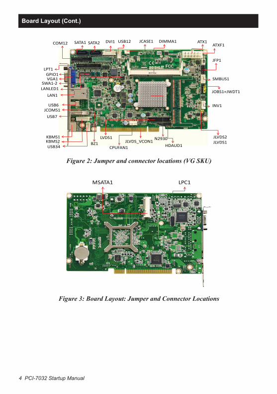
Figure 2: Jumper and connector locations (VG SKU)
Figure 3: Board Layout: Jumper and Connector Locations
“
COM12 SATA1 SATA2 USB12 JCASE1 DIMMA1 ATX1 ATXF1
JFP1
SMBUS1
JOBS1+JWDT1
INV1
JLVDS2
JLVDS1
N2930
HDAUD1
JLVDS_VCON1
CPUFAN1
1
LVDS1
BZ1
LPT1 GPIO1 VGA1
SWA1-2 LANLED1
LAN1
USB6 JCOMS1
USB7
KBMS1 KBMS2 USB34
DVI1
MSATA1 LPC1
Board Layout (Cont.)