pccp - pdfs.semanticscholar.org€¦structures of n-butane, n-pentane, n-hexane, 1-butene, cis and...
TRANSCRIPT

This is an Accepted Manuscript, which has been through the Royal Society of Chemistry peer review process and has been accepted for publication.
Accepted Manuscripts are published online shortly after acceptance, before technical editing, formatting and proof reading. Using this free service, authors can make their results available to the community, in citable form, before we publish the edited article. We will replace this Accepted Manuscript with the edited and formatted Advance Article as soon as it is available.
You can find more information about Accepted Manuscripts in the Information for Authors.
Please note that technical editing may introduce minor changes to the text and/or graphics, which may alter content. The journal’s standard Terms & Conditions and the Ethical guidelines still apply. In no event shall the Royal Society of Chemistry be held responsible for any errors or omissions in this Accepted Manuscript or any consequences arising from the use of any information it contains.
Accepted Manuscript
www.rsc.org/pccp
PCCP
Journal Name RSCPublishing
ARTICLE
This journal is © The Royal Society of Chemistry 2013 J . Name., 2013, 00, 1-3 | 1
Cite this: DOI: 10.1039/x0xx00000x
Received 00th January 2012,
Accepted 00th January 2012
DOI: 10.1039/x0xx00000x
www.rsc.org/
Adsorption structures of non-aromatic hydrocarbons
on silicalite-1 using single-crystal X-ray diffraction
method
Shinjiro Fujiyama,*a Shintaro Seino,
a Natsumi Kamiya,
a Koji Nishi,
a Kenji Yoza
b
and Yoshinobu Yokomoria,
The actual adsorption structures of non-aromatic hydrocarbons on the MFI-type zeolites have
not yet been determined. This is due to the presence of twinning, which makes crystallographic
analysis difficult. We recently overcame this problem 1, and now report the various adsorption
structures of n-butane, n-pentane, n-hexane, 1-butene, cis and trans-2-butene, 2-butyne and
isopentane on silicalite-1 (MFI-type zeolite) as determined via single-crystal X-ray diffraction.
The structures were elucidated for both low and high loadings of each guest molecule in order
to clarify the adsorption process. The low-loaded structures provide valuable insight into
guest-framework interactions and initial adsorption behavior. The n-alkanes are initially
adsorbed in the sinusoidal channel, while 2-butyne is adsorbed in the straight channel. In the
case of the normal hydrocarbons, the molecular configuration (bent or linear) of the compound
determines which channel is the preferred adsorption site. Bent molecules prefer the sinusoidal
channel and linear molecules prefer the straight channel. In contrast, isopentane is initially
adsorbed at the intersection, since the channels are too narrow to maintain the preferred
distance between the framework and the bulky isopentane molecule. In the high -loaded
structures, the guest molecules occupy additional sites, such that the normal hydrocarbons are
located in both channels and isopentane is found at the intersect ion and the sinusoidal channel.
1. Introduction
Zeolites are promising microporous materials due to their high
thermal, mechanical and chemical stability and, for this reason,
various applications in catalysis, gas separation and gas storage
have been suggested for these substances. Guest molecules in
the zeolite micropores are physisorbed in a stable manner even
at room temperature, mainly due to van der Waals interactions
with the pore walls. MFI-type zeolites such as ZSM-5 and
silicalite-1 have in particular attracted a significant amount of
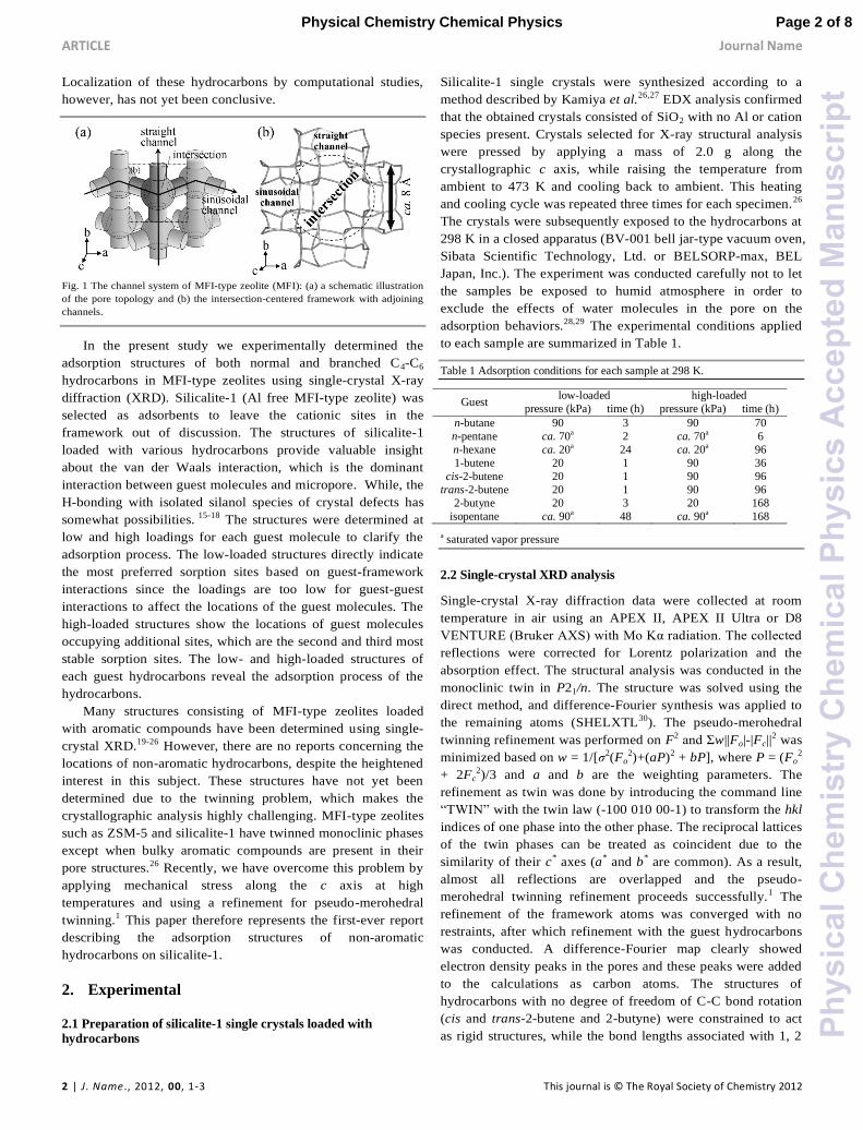
interest since they possess two kinds of unique channels. Figure
1 shows the channel system of MFI-type zeolites, which can be
divided into three types of sorption sites: straight channel,
sinusoidal channel and intersection. The locations of guest
molecules are vital to understanding the adsorption properties
of the material and this factor has received much attention in
recent years. There are a number of reports on adsorption of
various hydrocarbons on MFI-type zeolites2-9 and associated
thermodynamic information such as sorption isotherms, heat of
sorption and variation of entropy are well established. However,
there is currently no consensus concerning the localization of
hydrocarbons in the three-dimensional channel network. Jacobs
et al.2 has suggested that C3-C5 n-alkanes do not occupy
particular sites while C6-C8 n-alkanes fill up the straight
channel, and that packing in the sinusoidal channel is less dense.
Richards et al.3 proposed a sorption model in which a function
of sorbate loading describes the measured heat of sorption.
They assumed n-alkanes are preferentially located in the
channels and C4-C6 n-alkanes are located in the sinusoidal
rather than straight channel. Eder et al.6 determined that n-
alkanes are located in the sinusoidal channel and can also
populate the intersection at low loadings. These reports
provided valuable thermodynamic data which are useful in
terms of understanding the adsorption properties. However, it
would be impossible to derive precise locations of guest
molecules solely from the thermodynamic data. Computational
studies have also been conducted.10-14 June et al.10,12 concluded
that n-butane and n-hexane are absorbed in both channels in
roughly equal proportions, and branched alkanes such as 2- and
3-methylpentane are absorbed at the intersection. Smit et al.13
agree that the probabilities of the C4-C6 n-alkanes locating in
both channels are nearly equal. Maginn et al.14 showed that n-
butane and n-hexane are most likely found in the sinusoidal
channel, while Titiloye et al.11 reported that adsorption in the
straight channel is preferred in the case of C1-C8 n-alkanes.
Page 1 of 8 Physical Chemistry Chemical Physics
Phy
sica
lChe
mis
try
Che
mic
alP
hysi
csA
ccep
ted
Man
uscr
ipt
ARTICLE Journal Name
2 | J. Name., 2012, 00, 1-3 This journal is © The Royal Society of Chemistry 2012
Localization of these hydrocarbons by computational studies,
however, has not yet been conclusive.
Fig. 1 The channel system of MFI-type zeolite (MFI): (a) a schematic illustration
of the pore topology and (b) the intersection-centered framework with adjoining
channels.
In the present study we experimentally determined the
adsorption structures of both normal and branched C4-C6
hydrocarbons in MFI-type zeolites using single-crystal X-ray
diffraction (XRD). Silicalite-1 (Al free MFI-type zeolite) was
selected as adsorbents to leave the cationic sites in the
framework out of discussion. The structures of silicalite-1
loaded with various hydrocarbons provide valuable insight
about the van der Waals interaction, which is the dominant
interaction between guest molecules and micropore. While, the
H-bonding with isolated silanol species of crystal defects has
somewhat possibilities. 15-18 The structures were determined at
low and high loadings for each guest molecule to clarify the
adsorption process. The low-loaded structures directly indicate
the most preferred sorption sites based on guest-framework
interactions since the loadings are too low for guest-guest
interactions to affect the locations of the guest molecules. The
high-loaded structures show the locations of guest molecules
occupying additional sites, which are the second and third most
stable sorption sites. The low- and high-loaded structures of
each guest hydrocarbons reveal the adsorption process of the
hydrocarbons.
Many structures consisting of MFI-type zeolites loaded
with aromatic compounds have been determined using single-
crystal XRD.19-26 However, there are no reports concerning the
locations of non-aromatic hydrocarbons, despite the heightened
interest in this subject. These structures have not yet been
determined due to the twinning problem, which makes the
crystallographic analysis highly challenging. MFI-type zeolites
such as ZSM-5 and silicalite-1 have twinned monoclinic phases
except when bulky aromatic compounds are present in their
pore structures.26 Recently, we have overcome this problem by
applying mechanical stress along the c axis at high
temperatures and using a refinement for pseudo-merohedral
twinning.1 This paper therefore represents the first-ever report
describing the adsorption structures of non-aromatic
hydrocarbons on silicalite-1.
2. Experimental
2.1 Preparation of silicalite-1 single crystals loaded with
hydrocarbons
Silicalite-1 single crystals were synthesized according to a
method described by Kamiya et al.26,27 EDX analysis confirmed
that the obtained crystals consisted of SiO2 with no Al or cation
species present. Crystals selected for X-ray structural analysis
were pressed by applying a mass of 2.0 g along the
crystallographic c axis, while raising the temperature from
ambient to 473 K and cooling back to ambient. This heating
and cooling cycle was repeated three times for each specimen.26
The crystals were subsequently exposed to the hydrocarbons at
298 K in a closed apparatus (BV-001 bell jar-type vacuum oven,
Sibata Scientific Technology, Ltd. or BELSORP-max, BEL
Japan, Inc.). The experiment was conducted carefully not to let
the samples be exposed to humid atmosphere in order to
exclude the effects of water molecules in the pore on the
adsorption behaviors.28,29 The experimental conditions applied
to each sample are summarized in Table 1.
Table 1 Adsorption conditions for each sample at 298 K.
Guest low-loaded high-loaded
pressure (kPa) time (h) pressure (kPa) time (h)
n-butane 90 3 90 70
n-pentane ca. 70a 2 ca. 70a 6
n-hexane ca. 20a 24 ca. 20a 96
1-butene 20 1 90 36
cis-2-butene 20 1 90 96
trans-2-butene 20 1 90 96
2-butyne 20 3 20 168
isopentane ca. 90a 48 ca. 90a 168
a saturated vapor pressure
2.2 Single-crystal XRD analysis
Single-crystal X-ray diffraction data were collected at room
temperature in air using an APEX II, APEX II Ultra or D8
VENTURE (Bruker AXS) with Mo Kα radiation. The collected
reflections were corrected for Lorentz polarization and the
absorption effect. The structural analysis was conducted in the
monoclinic twin in P21/n. The structure was solved using the
direct method, and difference-Fourier synthesis was applied to
the remaining atoms (SHELXTL30). The pseudo-merohedral
twinning refinement was performed on F2 and Σw||Fo|-|Fc||2 was
minimized based on w = 1/[σ2(Fo2)+(aP)2 + bP], where P = (Fo
2
+ 2Fc2)/3 and a and b are the weighting parameters. The
refinement as twin was done by introducing the command line
“TWIN” with the twin law (-100 010 00-1) to transform the hkl
indices of one phase into the other phase. The reciprocal lattices
of the twin phases can be treated as coincident due to the
similarity of their c* axes (a* and b* are common). As a result,
almost all reflections are overlapped and the pseudo-
merohedral twinning refinement proceeds successfully.1 The
refinement of the framework atoms was converged with no
restraints, after which refinement with the guest hydrocarbons
was conducted. A difference-Fourier map clearly showed
electron density peaks in the pores and these peaks were added
to the calculations as carbon atoms. The structures of
hydrocarbons with no degree of freedom of C-C bond rotation
(cis and trans-2-butene and 2-butyne) were constrained to act
as rigid structures, while the bond lengths associated with 1, 2
Page 2 of 8Physical Chemistry Chemical Physics
Phy
sica
lChe
mis
try
Che
mic
alP
hysi
csA
ccep
ted
Man
uscr
ipt

Journal Name ARTICLE
This journal is © The Royal Society of Chemistry 2012 J . Name ., 2012, 00, 1-3 | 3
and 1, 3 distances were restrained in the other hydrocarbons. As
an example, the 1, 2 and 1, 3 distances of the saturated alkanes
were constrained at 1.53 and 2.54 Å, respectively. As a final
step, the structures incorporating the guest hydrocarbons were
successfully solved. Anisotropic displacement parameters were
used for the framework atoms and isotropic parameters were
used for the hydrocarbons. The crystal data and refinement
details are summarized in Table 2, and the full details are
available as CIF files in Supplementary Information. The
structures in Figs. 2 to 4 and 7 to 9 were generated using the
VESTA software package.31
Table 2 Crystal data and refinement details.
Crystal n-butane n-pentane
low-loaded high-loaded low-loaded high-loaded
Chemical formulaa Si24O48·0.9C4 Si24O48·2.0C4 Si24O48·1.0C5 Si24O48·2.0C5
Crystal size (mm3) 0.17 × 0.09 × 0.07 0.23 × 0.11 × 0.07 0.16 × 0.07 × 0.04 0.13 × 0.09 × 0.05
Independent reflections (Rint) 13290 (0.148) 12710 (0.144) 12993 (0.147) 13092 (0.110)
No. of restraints 5c 15c 7c 21c
No. of parameters 667 701 671 713
R1 (I > 2σ(I)), Rall 0.0555 (6076b), 0.1646 0.0506 (6752b), 0.1245 0.0594 (6408b), 0.1623 0.0492 (5585b), 0.1371
Δρmax and Δρmin (e Å-3) 1.15 and -0.79 0.64 and -0.82 1.05 and -0.61 0.62 and -0.57
Crystal n-hexane 1-butene
low-loaded high-loaded low-loaded high-loaded
Chemical formulaa Si24O48·0.7C6 Si24O48·2.0C6 Si24O48·1.1C4 Si24O48·2.0C4
Crystal size (mm3) 0.26 × 0.13 × 0.07 0.18 × 0.10 × 0.07 0.16 × 0.10 × 0.05 0.15 × 0.12 × 0.08
Independent reflections (Rint) 12034 (0.089) 12094 (0.152) 13278 (0.170) 13341 (0.103)
No. of restraints 9c 43c. d 10c 15c
No. of parameters 675 722 684 698
R1 (I > 2σ(I)), Rall 0.0416 (10366b), 0.0501 0.0455 (9106b), 0.0593 0.0525 (4054b), 0.1963 0.0498 (5700b), 0.1345
Δρmax and Δρmin (e Å-3) 0.96 and -0.55 0.81 and -0.68 0.64 and -0.57 0.54 and -0.50
Crystal cis-2-butene trans-2-butene
low-loaded high-loaded low-loaded high-loaded
Chemical formulaa Si24O48·0.8C4 Si24O48·1.1C4 Si24O48·1.1C4 Si24O48·1.9C4
Crystal size (mm3) 0.17 × 0.11 × 0.08 0.16 × 0.10 × 0.06 0.14 × 0.09 × 0.07 0.17 × 0.13 × 0.08
Independent reflections (Rint) 13037 (0.081) 13365 (0.085) 13015 (0.084) 12984 (0.064)
No. of restraints 0 0 0 0
No. of parameters 666 676 666 674
R1 (I > 2σ(I)), Rall 0.0484 (5784b), 0.1217 0.0486 (5411b), 0.1353 0.0513 (5390b), 0.1332 0.0464 (6609b), 0.1043
Δρmax and Δρmin (e Å-3) 0.88 and -0.49 0.86 and -0.57 0.92 and -0.47 0.92 and -0.44
Crystal 2-butyne isopentane
low-loaded high-loaded low-loaded high-loaded
Chemical formulaa Si24O48·0.2C4 Si24O48·1.8C4 Si24O48·0.3C5 Si24O48·2.0C5
Crystal size (mm3) 0.23 × 0.11 × 0.06 0.16 × 0.09 × 0.05 0.17 × 0.12 × 0.07 0.21 × 0.11 × 0.07
Independent reflections (Rint) 12810 (0.094) 12818 (0.132) 12864 (0.106) 13020 (0.107)
No. of restraints 0 15d. e 8c 16c
No. of parameters 661 676 671 692
R1 (I > 2σ(I)), Rall 0.0534 (6505b), 0.1164 0.0550 (5423b), 0.1506 0.0549 (6589b), 0.1203 0.0520 (5815b), 0.1269
Δρmax and Δρmin (e Å-3) 0.58 and -0.60 0.69 and -0.68 0.55 and -0.60 0.90 and -0.57
a 1.0 guest molecule for an asymmetric unit of framework (Si24O48) corresponds to a loading of 4.0 molecules per unit cell. The unit cell consists of 4
asymmetric units in P21/n.
b No. of reflections with I > 2σ(I) c restraints on the bond lengths of the guest hydrocarbons. d restraints on the displacement parameters of the guest hydrocarbons. e restraints on the occupancy factors of the guest hydrocarbons.
3. Results and Discussion
3.1 Adsorption of n-alkanes
Figure 2 shows the low-loaded n-alkane-silicalite-1 structures.
All alkanes are located in the centers of the sinusoidal channels,
which are determined to be the most stable sorption sites. The
occupancy factors, which are all equal to or close to 1.0,
indicate that the sinusoidal channels are almost fully occupied.
The n-alkanes are never observed at other sites, such as the
straight channel and intersection. The sinusoidal channel thus
represents a significantly stable sorption site for the n-alkanes.
The distances between neighboring n-alkanes, defined as the
internuclear distances between closest carbon atoms, are 6.46,
5.21 and 3.91 Å respectively for n-butane, n-pentane and n-
hexane. This distance decreases with increasing chain length
and thus end-to-end guest-guest interactions will be particularly
enhanced in the case of n-hexane.
Page 3 of 8 Physical Chemistry Chemical Physics
Phy
sica
lChe
mis
try
Che
mic
alP
hysi
csA
ccep
ted
Man
uscr
ipt

ARTICLE Journal Name
4 | J. Name., 2012, 00, 1-3 This journal is © The Royal Society of Chemistry 2012
Fig. 2 Low-loaded structures of (a) n-butane, (b) n-pentane and (c) n-hexane with
the occupancy factors shown in parentheses. The locations related to the 2 1 screw
axis along the a axis are shown in gray.
Fig. 3 presents the high-loaded structures determined for the
n-alkane-silicalite-1. The n-alkanes are located in the both
channels. The occupancy factors indicate the loadings consist
of eight molecules per unit cell, which is approximately equal
to the adsorption capacities of normal C4-C6 alkanes.2,3,7 The
fully-packed structures corresponding to the sorption of these n-
alkanes were determined. The distances between guest n-
alkanes are listed in Table 3. There exists considerable guest-
guest dispersion interaction in these high-loaded structures,
based on the short intermolecular distances. With the exception
of the SIN to STR1 n-hexane interaction, these compounds
interact in end-to-end structures.
The adsorption process of the n-alkanes is revealed by these
results. These compounds are initially adsorbed in the
sinusoidal channels, due to favorable guest-framework
interactions, until the sinusoidal channels are fully occupied at
four molecules per unit cell. The guest-guest interactions are
weak in this initial stage, although they are enhanced in the case
of n-hexane. Additional guest molecules are adsorbed in the
straight channel and guest-guest interactions subsequently arise.
Finally, both channels are fully occupied, at eight molecules per
unit cell. This process is in good agreement with the packing
model proposed by Richards et al.3 The model was derived
from the heats of sorption associated with various levels of
loading. The end-to-end guest-guest interactions of n-hexane in
the low-loaded structure at a distance of 3.91 Å clearly explain
the rapid increase in the heat of sorption over the loading range
of zero to four molecules per unit cell, with an increase of 20
kJ/mol.3 Even at low loading levels, n-hexane molecules in the
sinusoidal channels strongly interact with one another. A
moderate increase in the heat of sorption over the same low
loading range is also observed in case of n-butane (about 5
kJ/mol).3 This increase is caused by the interactions between n-
butane in the sinusoidal channel and n-butane at the other
locations such as straight channel or intersection, even though
n-butane molecules were not observed in the single XRD
measurements in the present study, since the associated
occupancy levels were too low. n-Pentane also shows an
increase in heat of sorption in the low loading range, on the
order of 18 kJ/mol.5 In addition to interactions with n-pentane
at the other locations (as seen in the case of n-butane), this
change in heat of sorption may also result from the end-to-end
guest-guest interactions of n-pentane in the sinusoidal channels
at a distance of 5.21 Å.
Fig. 3 High-loaded structures of (a) n-butane, (b) n-pentane and (c) n-hexane with
the occupancy factors shown in parentheses. The locations related to the 2 1 screw
axis along the a axis and the center of symmetry in the middle of the straight
channel are shown in gray.
Table 3 Internuclear distances (Å) between the closest carbon atoms of
neighboring n-alkanes in the high-loaded structures.
n-butane n-pentane n-hexane
SIN – STR1 3.91 4.49 3.97a
SIN – STR2 4.44 3.35 3.44
STR1 – STR2 6.18 3.18 2.94
a end atom of SIN to second atom from the end of STR1.
3.2 Adsorption of 2-butyne
Figure 4(a) shows the low-loaded structure of 2-butyne-
silicalite-1, in which the 2-butyne is located in the straight
channel. The guest-guest interactions in this structure are
negligibly small since the 2-butyne molecules are located
separately. The shortest distance between neighboring 2-butyne
molecules is 10 Å, which is too far to allow guest-guest
interactions. The structure clearly indicates that the straight
channel is the most stable sorption site based on the guest-
framework interactions. The molecular configuration (bent or
linear) determines which channel is the most stable site based
on guest-framework interactions. Bent molecules prefer the
sinusoidal channel and linear molecules prefer the straight
channel. Indeed, the bent dimethyl ether is initially adsorbed in
the sinusoidal channel32 while the linear CO2 is initially
adsorbed in the straight channel.33 These results may be
explained by the structural differences between the channels.
Fig. 4 (a) Low-loaded structure and (b) high-loaded structure of 2-butyne with the
occupancy factors shown in parentheses. The locations related to the 21 screw axis
along the a axis and the center of symmetry in the middle of the straight channel
are shown in gray.
Simple calculations of the Lennard-Jones potential are
useful as a means of estimating the stability of sorption sites
based on channel structures and guest molecule configurations.
The potential between an imaginary atom at an arbitrary
Page 4 of 8Physical Chemistry Chemical Physics
Phy
sica
lChe
mis
try
Che
mic
alP
hysi
csA
ccep
ted
Man
uscr
ipt

Journal Name ARTICLE
This journal is © The Royal Society of Chemistry 2012 J . Name ., 2012, 00, 1-3 | 5
position and the framework oxygen atoms around the channels
can be calculated using the well-known Equation (1).
( ) ∑ {( ) ( )
} (1)
Here (x, y, z) represents the arbitrary position of the imaginary
atom, ri is the distance between the atom and the framework
oxygen atom i, σ is the separation at which the potential
becomes zero, and ε is the depth of the potential well. The van
der Waals radius of the imaginary atom is set at 1.7 Å in
accordance with the radii of common atoms such as carbon,
nitrogen and oxygen. The 426 framework oxygen atoms around
the channels are counted in the calculation (i = 1 ~ 426). The
details of the calculation has been reported elsewhere.32 The
potential map of the resulting U(x, y, z) values reflects the
structural differences of the channels and a guest molecule at a
stable sorption site will locate its atoms where U(x, y, z) is low.
Fig. 5 shows the locations of the most stable sorption sites of
various guest molecules with the Lennard-Jones potential maps.
The potential is normalized to cancel an unknown factor 4ε. As
can be seen in Figs. 5(a) and (c), there are deep potential wells
in both channels. The depths of which are approximately the
same with a difference of less than 2%. This is not unexpected,
since the pore sizes are roughly the same. However, the
configuration of the potential wells is clearly different in the
two cases. Based on the minimum potential paths indicated by
the dashed lines, the path of the sinusoidal channel is winding
while that of the straight channel is linear. So the sinusoidal
channel is more favorable for bent molecules and the straight
channel is more favorable for linear molecules. The bent n-
butane is located within the winding minimum path and the
linear 2-butyne molecules are found along the linear minimum
path. Figs. 5(b) and (d) indicate the locations of the most stable
sorption sites for dimethyl ether32 and CO2.33 These locations
are almost identical to those determined for n-butane and 2-
butyne, as expected, since the locations are determined simply
on the basis of van der Waals interactions. As a result, the
locations at which the interaction potentials are minimized
should be similar.
Fig. 5 Locations of the most stable sorption sites for guest molecules with the
normalized Lennard-Jones potential maps: (a) n-butane in the sinusoidal channel,
(b) dimethyl ether in the sinusoidal channel,32 (c) 2-butyne in the straight channel
and (d) CO2 in the straight channel.33 The contour lines represent values ranging
from -0.95 to 0.00 in increments of 0.05. The potential minimum paths are
indicated by dashed lines.
Fig. 4(b) shows the high-loaded structure of 2-butyne-
silicalite-1. The internuclear distances between the closest
carbon atoms of neighboring 2-butyne molecules are 2.91 and
3.09 Å for the SIN1 to STR2 and SIN1 to STR1 locations,
respectively. Guest-guest interactions are at work in this
structure. The occupancy factors indicate that the level of
loading is 7.2 molecules per unit cell, which is comparable to
the reported saturation loading at 298 K of 9.40 molecules per
unit cell.4 The small difference between these values is due to
the extra sorption sites, which are highly disordered. These
sorption sites are much less stable and the associated occupancy
factors are too low to be observed on the basis of XRD. Unlike
the n-alkanes, the 2-butyne located in the sinusoidal channel is
in a state of disorder. This occurs because the potential well in
the sinusoidal channel is winding and the linear configurations
of the 2-butyne molecules prevent them from locating within
the winding well. As shown in Fig. 6, 2-butyne is located on the
linear part of the winding well.
The adsorption process of 2-butyne is similar to those of the
n-alkanes except for the initial sorption site. The 2-butyne
molecules are initially adsorbed in the straight channel due to
guest-framework interactions, while additional molecules are
adsorbed in the sinusoidal channel, leading to guest-guest
interactions. Finally, the both channels are almost fully
occupied (7.2 molecules per unit cell).
Fig. 6 SIN1, 2 of the high-loaded 2-butyne-silicalite-1 in the sinusoidal cannel,
with the normalized Lennard-Jones potential map. The contour lines represent
values ranging from -0.95 to 0.00 in increments of 0.05. The potential minimum
paths are indicated by dashed lines.
3.3 Adsorption of 1-butene and cis and trans-2-butene
Figure. 7 shows the low-loaded structures of 1-butene and cis
and trans-2-butene. These molecules are located in both
channels even at low loadings of about four molecules per unit
cell, indicating that the sorption stabilities of the channels are
similar. The initial adsorption behavior is intermediate between
those of the bent n-alkanes and the linear 2-butyne. Thus the
molecular configuration (bent or linear) or, in other words, the
bond angles within the guest molecule, is an important factor
that determines which channel is the most stable sorption site
for normal hydrocarbons. As the bond angles approach 180°,
the compounds exhibit a greater tendency to prefer the straight
channel. Fig. 8 shows the high-loaded structures of 1-butene
and cis and trans-2-butene, in which the guest molecules are
Page 5 of 8 Physical Chemistry Chemical Physics
Phy
sica
lChe
mis
try
Che
mic
alP
hysi
csA
ccep
ted
Man
uscr
ipt
ARTICLE Journal Name
6 | J. Name., 2012, 00, 1-3 This journal is © The Royal Society of Chemistry 2012
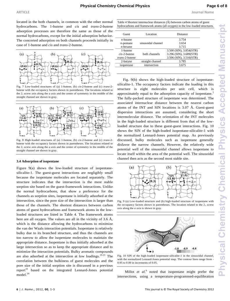
located in the both channels, in common with the other normal
hydrocarbons. The 1-butene and cis and trans-2-butene
adsorption processes are therefore the same as those of the
normal hydrocarbons, except for the initial adsorption behavior.
The concerted adsorption on both channels proceeds initially in
case of 1-butene and cis and trans-2-butene.
Fig. 7 Low-loaded structures of (a) 1-butene, (b) cis-2-butene and (c) trans-2-
butene with the occupancy factors shown in parentheses. The locations related to
the 21 screw axis along the a axis and the center of symmetry in the middle of the
straight channel are shown in gray.
Fig. 8 High-loaded structures of (a) 1-butene, (b) cis-2-butene and (c) trans-2-
butene with the occupancy factors shown in parentheses. The locations related to
the 21 screw axis along the a axis and the center of symmetry in the middle of the
straight channel are shown in gray.
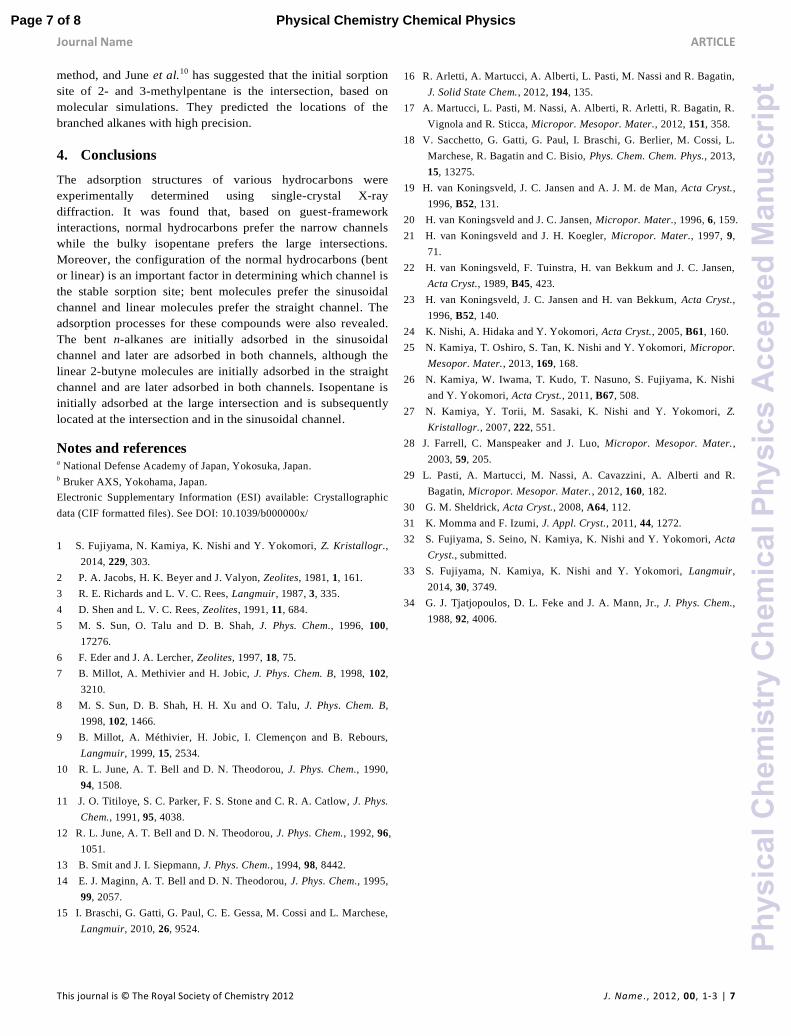
3.4 Adsorption of isopentane
Figure 9(a) shows the low-loaded structure of isopentane-
silicalite-1. The guest-guest interactions are negligibly small
because the isopentane molecules are located separately. The
structure indicates that the intersection is the most stable
sorption site based on the guest-framework interactions. Unlike
the normal hydrocarbons, that show a preference for the
channels as sorption sites, isopentane is initially adsorbed at the
intersection, since the pore size of the intersection is larger than
those of the channels. The shortest distances between carbon
atoms of guest hydrocarbons and framework atoms in the low-
loaded structures are listed in Table 4. The framework atoms
here are all oxygen. The values are all in the vicinity of 3.6 Å,
which is the distance allowing the hydrocarbons to minimize
the van der Waals interaction potentials. Isopentane is relatively
bulky due to its branched structure, and thus the channels are
too narrow to allow the isopentane molecules to maintain the
appropriate distance. Isopentane is thus initially adsorbed at the
large intersection so as to keep the appropriate distance and to
minimize the interaction potentials. Bulky aromatic compounds
are also adsorbed at the intersection at low loadings.19-21 The
correlation between the bulkiness of guest molecules and the
pore size of the initial sorption site is discussed in a previous
report33 based on the integrated Lennard-Jones potential
model.34
Table 4 Shortest internuclear distances (Å) between carbon atoms of guest
hydrocarbons and framework atoms (all oxygen) in the low-loaded structures.
Guest Location Distance
n-butane
sinusoidal channel
3.754
n-pentane 3.654
n-hexane 3.715
1-butene
both channels
3.500 (SIN), 3.854(STR)
cis-2-butene 3.296 (SIN), 3.689(STR)
trans-2-butene 3.506 (SIN), 3.516(STR)
2-butyne straight channel 3.785
isopentane intersection 3.675
Fig. 9(b) shows the high-loaded structure of isopentane-
silicalite-1. The occupancy factors indicate the loading in this
structure is eight molecules per unit cell, which is
approximately equal to the adsorption capacity of isopentane.2
The fully-packed structure of isopentane was determined. The
associated internuclear distance between the nearest carbon
atoms of the INT and SIN locations is 3.07 Å. Guest-guest
dispersion interactions are assumed, considering the short
intermolecular distance. The orientation of the INT molecules
in the high-loaded structure is different from that of the low-
loaded structure due to these guest-guest interactions. Fig. 10
shows the SIN of the high-loaded isopentane-silicalite-1 with
the normalized Lennard-Jones potential map. As previously
discussed, bulky molecules such as isopentane generally
disfavor the narrow channels. However, the relatively wide
potential well of the sinusoidal channel allows isopentane to
locate itself within the area of the potential well. The sinusoidal
channel then acts as the second most stable site.
Fig. 9 (a) Low-loaded structure and (b) high-loaded structure of isopentane with
the occupancy factors shown in parentheses. The location related to the 2 1 screw
axis along the a axis is shown in gray.
Fig. 10 SIN of the high-loaded isopentane-silicalite-1 in the sinusoidal channel,
with the normalized Lennard-Jones potential map. The contour lines range from -
0.95 to 0.00 in increments of 0.05.
Millot et al.9 noted that isopentane might prefer the
intersections, using a temperature-programmed-equilibration
Page 6 of 8Physical Chemistry Chemical Physics
Phy
sica
lChe
mis
try
Che
mic
alP
hysi
csA
ccep
ted
Man
uscr
ipt
Journal Name ARTICLE
This journal is © The Royal Society of Chemistry 2012 J . Name ., 2012, 00, 1-3 | 7
method, and June et al.10 has suggested that the initial sorption
site of 2- and 3-methylpentane is the intersection, based on
molecular simulations. They predicted the locations of the
branched alkanes with high precision.
4. Conclusions
The adsorption structures of various hydrocarbons were
experimentally determined using single-crystal X-ray
diffraction. It was found that, based on guest-framework
interactions, normal hydrocarbons prefer the narrow channels
while the bulky isopentane prefers the large intersections.
Moreover, the configuration of the normal hydrocarbons (bent
or linear) is an important factor in determining which channel is
the stable sorption site; bent molecules prefer the sinusoidal
channel and linear molecules prefer the straight channel. The
adsorption processes for these compounds were also revealed.
The bent n-alkanes are initially adsorbed in the sinusoidal
channel and later are adsorbed in both channels, although the
linear 2-butyne molecules are initially adsorbed in the straight
channel and are later adsorbed in both channels. Isopentane is
initially adsorbed at the large intersection and is subsequently
located at the intersection and in the sinusoidal channel.
Notes and references a National Defense Academy of Japan, Yokosuka, Japan. b Bruker AXS, Yokohama, Japan.
Electronic Supplementary Information (ESI) available: Crystallographic
data (CIF formatted files). See DOI: 10.1039/b000000x/
1 S. Fujiyama, N. Kamiya, K. Nishi and Y. Yokomori, Z. Kristallogr.,
2014, 229, 303.
2 P. A. Jacobs, H. K. Beyer and J. Valyon, Zeolites, 1981, 1, 161.
3 R. E. Richards and L. V. C. Rees, Langmuir, 1987, 3, 335.
4 D. Shen and L. V. C. Rees, Zeolites, 1991, 11, 684.
5 M. S. Sun, O. Talu and D. B. Shah, J. Phys. Chem., 1996, 100,
17276.
6 F. Eder and J. A. Lercher, Zeolites, 1997, 18, 75.
7 B. Millot, A. Methivier and H. Jobic, J. Phys. Chem. B, 1998, 102,
3210.
8 M. S. Sun, D. B. Shah, H. H. Xu and O. Talu, J. Phys. Chem. B,
1998, 102, 1466.
9 B. Millot, A. Méthivier, H. Jobic, I. Clemençon and B. Rebours,
Langmuir, 1999, 15, 2534.
10 R. L. June, A. T. Bell and D. N. Theodorou, J. Phys. Chem., 1990,
94, 1508.
11 J. O. Titiloye, S. C. Parker, F. S. Stone and C. R. A. Catlow, J. Phys.
Chem., 1991, 95, 4038.
12 R. L. June, A. T. Bell and D. N. Theodorou, J. Phys. Chem., 1992, 96,
1051.
13 B. Smit and J. I. Siepmann, J. Phys. Chem., 1994, 98, 8442.
14 E. J. Maginn, A. T. Bell and D. N. Theodorou, J. Phys. Chem., 1995,
99, 2057.
15 I. Braschi, G. Gatti, G. Paul, C. E. Gessa, M. Cossi and L. Marchese,
Langmuir, 2010, 26, 9524.
16 R. Arletti, A. Martucci, A. Alberti, L. Pasti, M. Nassi and R. Bagatin,
J. Solid State Chem., 2012, 194, 135.
17 A. Martucci, L. Pasti, M. Nassi, A. Alberti, R. Arletti, R. Bagatin, R.
Vignola and R. Sticca, Micropor. Mesopor. Mater., 2012, 151, 358.
18 V. Sacchetto, G. Gatti, G. Paul, I. Braschi, G. Berlier, M. Cossi, L.
Marchese, R. Bagatin and C. Bisio, Phys. Chem. Chem. Phys., 2013,
15, 13275.
19 H. van Koningsveld, J. C. Jansen and A. J. M. de Man, Acta Cryst.,
1996, B52, 131.
20 H. van Koningsveld and J. C. Jansen, Micropor. Mater., 1996, 6, 159.
21 H. van Koningsveld and J. H. Koegler, Micropor. Mater., 1997, 9,
71.
22 H. van Koningsveld, F. Tuinstra, H. van Bekkum and J. C. Jansen,
Acta Cryst., 1989, B45, 423.
23 H. van Koningsveld, J. C. Jansen and H. van Bekkum, Acta Cryst.,
1996, B52, 140.
24 K. Nishi, A. Hidaka and Y. Yokomori, Acta Cryst., 2005, B61, 160.
25 N. Kamiya, T. Oshiro, S. Tan, K. Nishi and Y. Yokomori, Micropor.
Mesopor. Mater., 2013, 169, 168.
26 N. Kamiya, W. Iwama, T. Kudo, T. Nasuno, S. Fujiyama, K. Nishi
and Y. Yokomori, Acta Cryst., 2011, B67, 508.
27 N. Kamiya, Y. Torii, M. Sasaki, K. Nishi and Y. Yokomori, Z.
Kristallogr., 2007, 222, 551.
28 J. Farrell, C. Manspeaker and J. Luo, Micropor. Mesopor. Mater.,
2003, 59, 205.
29 L. Pasti, A. Martucci, M. Nassi, A. Cavazzini, A. Alberti and R.
Bagatin, Micropor. Mesopor. Mater., 2012, 160, 182.
30 G. M. Sheldrick, Acta Cryst., 2008, A64, 112.
31 K. Momma and F. Izumi, J. Appl. Cryst., 2011, 44, 1272.
32 S. Fujiyama, S. Seino, N. Kamiya, K. Nishi and Y. Yokomori, Acta
Cryst., submitted.
33 S. Fujiyama, N. Kamiya, K. Nishi and Y. Yokomori, Langmuir,
2014, 30, 3749.
34 G. J. Tjatjopoulos, D. L. Feke and J. A. Mann, Jr., J. Phys. Chem.,
1988, 92, 4006.
Page 7 of 8 Physical Chemistry Chemical Physics
Phy
sica
lChe
mis
try
Che
mic
alP
hysi
csA
ccep
ted
Man
uscr
ipt

The adsorption structures of the various hydrocarbons on silicalite-1 are revealed
experimentally using single-crystal X-ray method.
Page 8 of 8Physical Chemistry Chemical Physics
Phy
sica
lChe
mis
try
Che
mic
alP
hysi
csA
ccep
ted
Man
uscr
ipt