pcaslab user’s manual - structurepoint · evaluation software license agreement portland cement...
TRANSCRIPT

pcaSlab
User’s Manual
pcaSlab 1.10
CONCRETE SOFTWARE SOLUTIONS
August 2004

Table of Contents
Table of Contents 2
Legal and Contact Information 7 Copyright Information ..........................................................................................................7 Evaluation Software License Agreement ............................................................................8 Software License Agreement ............................................................................................14 PcaStructurePoint Contact Information .............................................................................20 Bug Report Form ...............................................................................................................20
Introduction to pcaSlab 23 Program Features..............................................................................................................23 Program Capacity..............................................................................................................23 System Requirements .......................................................................................................26 Terms and Conventions ....................................................................................................27
Ch. 1 Installing the Program 28 Running Program Installation ............................................................................................28 Purchasing and Licensing Process ...................................................................................35 Running the Program ........................................................................................................41 Removing the Program......................................................................................................41
Ch. 2 Method of Solution 42 Method of Solution.............................................................................................................42 Geometric Consistency Checks ........................................................................................42 Geometric Code Checks ...................................................................................................42 Slab Dimensions................................................................................................................42 Drop Panel Dimensions.....................................................................................................42 Column Capital Dimensions ..............................................................................................44 Minimum Slab Thickness of Flat Plate, Flat Slab and Beam-Supported Slab Systems ...45 Minimum Thickness for Waffle Slab Systems ...................................................................47 Waffle Rib Dimensions ......................................................................................................47 Special Considerations for Waffle Slabs ...........................................................................48 Material Properties ............................................................................................................50 The Equivalent Frame Method ..........................................................................................53 Stiffness Characteristics ....................................................................................................55 Loading ..............................................................................................................................64 Self-Weight ........................................................................................................................64 Superimposed Loading......................................................................................................64 Lateral Loading..................................................................................................................64 Loading Patterns ...............................................................................................................65 Load Combinations............................................................................................................67 Column and Middle Strip Widths .......................................................................................68 Design Moments................................................................................................................72 Shear Analysis of Slabs.....................................................................................................75 Critical Section for Interior Supports of Interior Frames ....................................................78 Critical Section for Exterior Supports of Interior Frames...................................................79 Critical Section for Interior Supports of Exterior Frames...................................................79 Critical Section for Exterior Supports of Exterior Frames..................................................80 Computation of Allowable Shear Stress at Critical Section...............................................81 Computation of Factored Shear Force at Critical Section.................................................82 Computation of Unbalanced Moment at Critical Section...................................................82
2

Computation of Shear Stresses at Critical Section ...........................................................82 Shear Resistance at Corner Columns...............................................................................84 Shear Analysis of Longitudinal Beams..............................................................................84 Area of Reinforcement.......................................................................................................87 Reinforcement Selection ...................................................................................................90 Additional Reinforcement at Support.................................................................................94 Integrity Reinforcement .....................................................................................................95 Corner Reinforcement .......................................................................................................95 Deflection Calculation........................................................................................................95 Cracking.............................................................................................................................97 Deflection Computations .................................................................................................100 Material Quantities...........................................................................................................101
Ch. 3 User Interface Description 102 User Interface Components.............................................................................................102
Check Boxes .............................................................................................................102 Checked Menu Commands ......................................................................................102 Command Buttons ....................................................................................................103 Control Menu.............................................................................................................104 Dialog Boxes .............................................................................................................104 Drop-down List ..........................................................................................................105 Drop-down Menu.......................................................................................................106 Enable/Disable Options ............................................................................................106 Frame Boxes.............................................................................................................107 List Boxes..................................................................................................................108 Option Buttons ..........................................................................................................110 Pop-up Menu.............................................................................................................111 Tabs ..........................................................................................................................112 Text Boxes ................................................................................................................113
Main Window ...................................................................................................................114 Main Window.............................................................................................................114 Title Bar.....................................................................................................................114 Menu Line .................................................................................................................115 Tool Bar.....................................................................................................................115 View Windows...........................................................................................................116 Status Bar .................................................................................................................117
Main Menu.......................................................................................................................118 File Menu ..................................................................................................................118 Input Menu ................................................................................................................121 Solve Menu ...............................................................................................................130 View Menu ................................................................................................................132 Options Menu............................................................................................................136 Window Menu ...........................................................................................................138 Help Menu.................................................................................................................139 The Control Menu .....................................................................................................140
Program Toolbar..............................................................................................................141 Toolbar ......................................................................................................................141
Program Input Wizard......................................................................................................144 Input Wizard ..............................................................................................................144
Program Input Dialog Windows.......................................................................................144 Input Dialog Windows ...............................................................................................144
Program Output Dialog Windows ....................................................................................150 Output Dialog Windows ............................................................................................150
Ch. 4 Operating the Program 151 Working with Data Files (menu File) ...............................................................................151
3

Creating a New Data File..........................................................................................151 Opening Existing Data File .......................................................................................151 Importing ADOSS Data File ......................................................................................152 Saving the Data File..................................................................................................153 Most Recently Used Files (MRU)..............................................................................154
Specifying the Model Data (menu Input) .........................................................................155 Data Input Wizard .....................................................................................................155
Data Input Wizard...............................................................................................155 General Information ..................................................................................................155
Defining General Information .............................................................................155 Material Properties ....................................................................................................156
Defining Material Properties ...............................................................................156 Spans ........................................................................................................................158
Defining the Slabs ..............................................................................................158 Defining the Longitudinal Beams........................................................................160 Defining the Ribs ................................................................................................162
Supports....................................................................................................................163 Defining the Columns .........................................................................................163 Defining the Drop Panels....................................................................................165 Defining the Column Capitals.............................................................................168 Defining the Transverse Beams .........................................................................169
Reinforcement Criteria ..............................................................................................171 Defining the Reinforcement Criteria for Slabs and Ribs.....................................171 Defining the Reinforcement Criteria for Beams..................................................173
Reinforcing Bars........................................................................................................174 Defining Column Strip Bars ................................................................................174 Defining Middle Strip Bars..................................................................................176 Defining Beam Bars............................................................................................177 Defining Beam Stirrups.......................................................................................179
Load Cases ...............................................................................................................180 Defining Load Cases ..........................................................................................180
Load Combinations ...................................................................................................182 Defining Load Combinations ..............................................................................182
Span Loads ...............................................................................................................183 About Loads .......................................................................................................183 Defining Area Load on Span ..............................................................................184 Defining Line Load on Span ...............................................................................185 Defining Point Force on Span.............................................................................187 Defining Point Moment on Span.........................................................................188
Lateral Effects ...........................................................................................................190 Defining Lateral Effects ......................................................................................190
Executing the Calculations (menu Solve)........................................................................191 Solve Options............................................................................................................191 Execute .....................................................................................................................191
View Program Output (menu View).................................................................................192 Change View Options ...............................................................................................192
Zooming in on the Floor System ........................................................................192 Change the Isometric View Angle ......................................................................193 Viewing the Specific Member Type ....................................................................194 Plan View............................................................................................................195 Elevated View.....................................................................................................197 Side View............................................................................................................198 Isometric View ....................................................................................................199 Loads..................................................................................................................201
View Results Report..................................................................................................202 Viewing Results Report ......................................................................................202
4

Saving Results Report........................................................................................203 View Graphical Results.............................................................................................205
Viewing the Shear and Moment Diagrams.........................................................205 Viewing the Moment Capacity............................................................................206 Viewing the Shear Capacity ...............................................................................208 Viewing the Reinforcement.................................................................................209 Viewing the Deflected Shapes ...........................................................................210
Print Results..............................................................................................................212 Printing the Analysis and Design Results...........................................................212 Printing the Current View Window......................................................................212
Print Preview.............................................................................................................213 Print Preview ......................................................................................................213
Copy Graphs to Clipboard ........................................................................................215 Copy Bitmap (BMP format).................................................................................215 Copy Metafile (EMF format) ...............................................................................215
Customizing Program (menu Options) ............................................................................216 Changing Colors .......................................................................................................216 Changing Startup Defaults........................................................................................217 Changing the Rebar Database .................................................................................218
Working with View Windows (menu Window) .................................................................219 Cascade ....................................................................................................................219 Tile Horizontal ...........................................................................................................219 Tile Vertical ...............................................................................................................219 Remaining Commands .............................................................................................219
Obtaining Help Information (menu Help).........................................................................220 Opening Help in Contents mode...............................................................................220 Opening Help in Index Mode ....................................................................................220 Obtaining the Program Version.................................................................................220
Ch. 5 Output Description 222 Output Elements..............................................................................................................222 Program Version..............................................................................................................222 Input Echo........................................................................................................................222 Design Results ................................................................................................................224 Column Axial Forces And Moments ................................................................................227 Segmental Moment And Shear - Load Cases.................................................................227 Segmental Moment And Shear - Load Combinations.....................................................228 Segmental Moment And Shear - Envelopes ...................................................................228 Segmental Deflections.....................................................................................................228 Graphical Output .............................................................................................................228
Ch. 6 Examples 230 Flat Slab...........................................................................................................................230
Problem Description..................................................................................................230 Calculation Results - Text Output .............................................................................231 Calculation Results - Graphical Output.....................................................................238
Beam-Supported Slab .....................................................................................................241 Problem Description..................................................................................................241 Calculation Results - Text Output .............................................................................242 Calculation Results - Graphical Output.....................................................................251
Appendix 254 Appendix A: Conversion Factors.....................................................................................254
Conversion Factors - U.S. to SI ................................................................................254 Conversion Factors - SI to U.S. ...............................................................................254
Appendix B: Bar Sizes.....................................................................................................255
5

ASTM English Bar Sizes - English Units...................................................................255 ASTM English Bar Sizes - Metric Units.....................................................................255 ASTM Metric Bar Sizes - English Units.....................................................................256 ASTM Metric Bar Sizes - Metric Units.......................................................................256 European Bar Sizes - English Units..........................................................................256 European Bar Sizes - Metric Units............................................................................257
Appendix C: References..................................................................................................258 References................................................................................................................258
6

Legal and Contact Information Copyright Information
Copyright Notice
Copyright (c) 2003 Portland Cement Association. All Rights Reserved.
Trademarks
pcaSlab is a registered trademark of Portland Cement Association. Windows is a registered trademark of Microsoft Corporation, Inc. Sentinel LM is a registered trademark of Rainbow Technology. Wise Installation System is a registered trademark of Wise Solutions, Inc. Other product and company names mentioned herein may be the trademarks of their respective owners. Any rights not expressly granted herein are reserved.
7

Evaluation Software License Agreement
PORTLAND CEMENT ASSOCIATION EVALUATION SOFTWARE LICENSE AGREEMENT
BY CLICKING THE ACCEPTED ICON BELOW, OR BY INSTALLING, COPYING, OR OTHERWISE USING THE SOFTWARE OR USER DOCUMENTATION, YOU AGREE TO BE BOUND BY THE TERMS OF THIS AGREEMENT, INCLUDING, BUT NOT LIMITED TO, THE WARRANTY DISCLAIMERS, LIMITATIONS OF LIABILITY AND TERMINA TION PROVISIONS BELOW. IF YOU DO NOT AGREE TO THE TERMS OF THIS AGREEMENT, DO NOT INSTALL OR USE THE SOFTWARE OR USER DOCUMENTA TION, EXIT THIS APPLICATION NOW AND RETURN THE SOFTWARE AND USER DOCUMENTATION TO PCA.
PORTLAND CEMENT ASSOCIATION, 5420 OLD ORCHARD ROAD, SKOKIE, ILLI NOIS 60077 (HEREAFTER PCA), GRANTS THE CUSTOMER A PERSONAL, NONEX CLUSIVE, LIMITED, NONTRANSFERABLE LICENSE TO USE THIS SOFTWARE AND USER DOCUMEN TA TION SOLELY FOR TRIAL AND EVALUATION PURPOSES ONLY IN ACCORDANCE WITH THE TERMS AND CONDITIONS OF THIS AGREEMENT. SOFT WARE AND USER DOCUMENTATION IS SUPPLIED TO CUSTOMER EITHER BY PCA DIRECTLY OR THROUGH AN AUTHORIZED DEALER OF PCA (HEREAFTER DEALER).
WHILE PCA HAS TAKEN PRECAUTIONS TO ASSURE THE CORRECTNESS OF THE ANALYTICAL SOLUTION AND DESIGN TECHNIQUES USED IN THIS SOFTWARE, IT CANNOT AND DOES NOT GUARANTEE ITS PERFORMANCE, NOR CAN IT OR DOES IT BEAR ANY RESPONSIBILITY FOR DEFECTS OR FAILURES IN STRUCTURES IN CONNECTION WITH WHICH THIS SOFTWARE MAY BE USED. DEALER (IF ANY) HAS NOT PARTICIPATED IN THE DESIGN OR DEVELOPMENT OF THIS SOFTWARE AND NEITHER GUARANTEES THE PERFORMANCE OF THE SOFTWARE NOR BEARS ANY RESPONSIBILITY FOR DEFECTS OR FAILURES IN STRUCTURES IN CONNEC TION WITH WHICH THIS SOFTWARE IS USED.
PCA AND DEALER (IF ANY) EXPRESSLY DISCLAIM ANY WARRANTY THAT: (A) THE FUNCTIONS CONTAINED IN THE SOFTWARE WILL MEET THE REQUIRE MENTS OF CUSTOMER OR OPERATE IN COMBINATIONS THAT MAY BE SE LECTED FOR USE BY CUSTOMER; (B) THE OPERATION OF THE SOFTWARE WILL BE FREE OF ALL "BUGS" OR PROGRAM ERRORS; OR (C) THE SOFTWARE CON FORMS TO ANY PERFORMANCE SPECIFICATIONS. CUSTOMER ACKNOWLEDGES THAT PCA IS UNDER NO OBLIGATION TO PROVIDE ANY SUPPORT, UPDATES, BUG FIXES OR ERROR CORRECTIONS TO OR FOR THE SOFTWARE OR USER DOCUMENTATION.
THE LIMITED WARRANTIES IN SECTION 6 HEREOF ARE IN LIEU OF ALL OTHER WARRANTIES, EXPRESS OR IMPLIED, INCLUDING, BUT NOT LIMITED TO, ANY IMPLIED WARRANTIES OF NON-INFRINGEMENT, MERCHANTABILITY OR FIT NESS FOR A PARTICULAR PURPOSE, EACH OF WHICH IS HEREBY DIS CLAIMED. EXCEPT AS SET FORTH IN SECTION 6, THE SOFTWARE AND USER DOCUMENTA TION ARE PROVIDED ON AN "AS-IS" BASIS.
8
IN NO EVENT SHALL PCA OR DEALER (IF ANY) BE LIABLE FOR: (A) LOSS OF PROFITS, DIRECT, INDIRECT, INCIDENTAL, SPECIAL, EXEMPLARY, PUNITIVE, CONSE QUEN TIAL OR OTHER DAMAGES, EVEN IF PCA OR DEALER (IF ANY) HAS BEEN ADVISED OF THE POSSIBILITY OF SUCH DAMAGES; (B) ANY CLAIM AGAINST CUSTOMER BY ANY THIRD PARTY; OR (C) ANY DA MAGES CAUSED BY (1) DELAY IN DELIVERY OF THE SOFT WARE OR USER DOCUMEN TATION UNDER THIS AGREEMENT; (2) THE PERFORMANCE OR NON PERFORMANCE OF THE SOFTWARE; (3) RESULTS FROM USE OF THE SOFTWARE OR USER DOCU MENTA TION, INCLUDING, WITHOUT LIMI TA TION, MISTAKES, ERRORS, INAC CURACIES, FAILURES OR CUSTOMER'S INABILITY TO PROVIDE SERVICES TO THIRD PARTIES THROUGH USE OF THE SOFTWARE OR USER DOCUMENTA TION; (4) CUSTOMER'S FAILURE TO PERFORM CUSTOMER'S RESPON SIBILI TIES; (5) PCA NOT PROVIDING UPDATES, BUG FIXES OR CORRECTIONS TO OR FOR ANY OF THE SOFTWARE OR USER DOCUMENTATION; (6) LABOR, EX PENSE OR MATERIALS NECESSARY TO REPAIR DAMAGE TO THE SOFTWARE OR USER DOCUMENTATION CAUSED BY (a) ACCI DENT, (b) NEGLI GENCE OR ABUSE BY CUSTOMER, (c) ACTS OF THIRD PERSONS INCLUDING, BUT NOT LIMITED TO, INSTALLATION, REPAIR, MAINTENANCE OR OTHER CORREC TIVE WORK RELATED TO ANY EQUIPMENT BEING USED, (d) CAUSES EXTER NAL TO THE SOFTWARE SUCH AS POWER FLUCTUATION AND FAILURES, OR (e) FLOODS, WINDSTORMS OR OTHER ACTS OF GOD. MOREOVER, IN NO EVENT SHALL PCA BE LIABLE FOR WARRANTIES, GUARANTEES, REPRE SEN TA TIONS OR ANY OTHER UNDERSTAN DINGS BETWEEN CUSTOMER AND DEALER (IF ANY) RELATING TO THE SOFT WARE OR USER DOCUMENTATION.
THIS AGREEMENT CONSTITUTES THE ENTIRE AND EXCLUSIVE AGREEMENT BETWEEN CUSTOMER AND PCA AND DEALER (IF ANY) WITH RESPECT TO THE SOFTWARE AND USER DOCUMENTATION TO BE FURNISHED HEREUNDER. IT IS A FINAL EXPRESSION OF THAT AGREEMENT AND UNDERSTANDING. IT SUPER SEDES ALL PRIOR COMMUNICATIONS BETWEEN THE PARTIES (INCLUDING ANY EVALUATION LICENSE AND ALL ORAL AND WRITTEN PROPOSALS). ORAL STATEMENTS MADE BY PCA'S OR DEALER'S (IF ANY) REPRESENTATIVES ABOUT THE SOFTWARE OR USER DOCU MEN TATION DO NOT CONSTITUTE REPRESEN TA TIONS OR WARRANTIES, SHALL NOT BE RELIED ON BY CUSTOMER, AND ARE NOT PART OF THIS AGREEMENT.
1. LICENSE RESTRICTIONS
(a) Except as expressly provided in this Agreement or as otherwise authorized in writing by PCA, Customer has no right to: (1) use, print, copy, display, reverse assemble, reverse engineer, translate or decompile the Software or User Documentation in whole or in part; (2) disclose, publish, release, sublicense or transfer to another person any Software or User Documentation; (3) reproduce the Software or User Documentation for the use or benefit of anyone other than Customer; or (4) modify any Software or User Documentation. All rights to the Software and User Documentation not expressly granted to Customer hereunder are retained by PCA. All copyrights and other proprietary rights except as expressed elsewhere in the Software or User Documentation and legal title thereto shall remain in PCA. Customer may use the Software at only one designated workstation at Customer's site at any given time. Customer may not transmit the Software electronically to any other workstation, computer, node or terminal device whether via a local area network, a wide area network, telecommunications transmission, the Internet or other means now known or hereafter created without prior written permission by PCA.
9

(b) Customer acknowledges that this is a limited license for trial and evaluation purposes only. This limited license shall automatically terminate upon the earlier of: (1) ten executions of the Software on the computer on which it is installed; or (2) fifteen days after the installation of the Software. Thereafter, Customer may only use the Software and Documentation if it acquires a production license for the same.
2. TERM AND TERMINATION
(a) This Agreement shall be in effect from the date Customer clicks the accepted icon below or installs, copies or otherwise uses the Software or User Documentation until: (1) it is terminated by Customer, by Dealer (if any) on behalf of Customer or PCA or by PCA as set forth herein; or (2) the limited trial and evaluation license terminates.
(b) This Agreement may be terminated by PCA without cause upon 30 days' written notice or immediately upon notice to Customer if Customer breaches this Agreement or fails to comply with any of its terms or conditions. This Agreement may be terminated by Customer without cause at any time upon written notice to PCA.
3. BACKUP AND REPLACEMENT COPIES
Customer may make one copy of the Software for back-up and archival purposes only, provided PCA's copyright and other proprietary rights notices are included on such copy.
4. PROTECTION AND SECURITY
(a) Customer shall not provide or otherwise make available any of the Software or User Documentation in any form to any person other than employees of Customer with the need to know, without PCA's written permission.
(b) All Software and User Documentation in Customer's possession including, with out limitation, translations, compilations, back-up, and partial copies is the property of PCA. Upon termination of this Agreement for any reason, Customer shall immediately destroy all Software and User Documentation, including all media, and destroy any Software that has been copied onto other magnetic storage devices. Upon PCA’s request, Customer shall certify its compliance in writing with the foregoing to PCA.
(c) Customer shall take appropriate action, by instruction, agreement or otherwise, with any persons permitted access to the Software or User Documentation, to enable Customer to satisfy its obligations under this Agreement with respect to use, copying, protection, and security of the same.
(d) If PCA prevails in an action against Customer for breach of the provisions of this Section 4, Customer shall pay the reasonable attorneys' fees, costs, and expenses incurred by PCA in connection with such action in addition to any award of damages.
5. CUSTOMER'S RESPONSIBILITIES
The essential purpose of this Agreement is to provide Customer with limited use rights to the Software and User Documentation. Customer accepts full responsibility for: (a)
10

selection of the Software and User Documentation to satisfy Customer's business needs and achieve Customer's intended results; (b) the use, set-up and installation of the Software and User Documentation; (c) all results obtained from use of the Software and User Documentation; and (d) the selection, use of, and results obtained from any other software, programming equipment or services used with the Software or User Documentation.
6. LIMITED WARRANTIES
PCA and Dealer (if any) warrants to Customer that: (a) PCA and Dealer (if any) has title to the Software and User Documentation and/or the right to grant Customer the rights granted hereunder; (b) the Software and User Documentation provided hereunder is PCA's most current production version thereof; and (c) the copy of the Software provided hereunder is an accurate reproduction of the original from which it was made.
7. LIMITATION OF REMEDY
(a) PCA AND DEALER (IF ANY) HAS NO LIABILITY UNDER THIS AGREEMENT. CUSTOMER'S EX CLUSIVE REMEDY FOR DAMAGES DUE TO PERFORMANCE OR NONPER FOR MANCE OF ANY SOFTWARE OR USER DOCU MENTATION, PCA, DEALER (IF ANY), OR ANY OTHER CAUSE WHATSO EVER, AND REGARDLESS OF THE FORM OF ACTION, WHETHER IN CONTRACT OR IN TORT, INCLUDING NEGLIGENCE, SHALL BE LIMITED TO CUSTOMER STOP PING ALL USE OF THE SOFTWARE AND USER DOCUMENTATION AND RETUR NING THE SAME TO PCA.
(b) NEITHER PCA NOR DEALER (IF ANY) IS AN INSURER WITH RE GARD TO THE PERFORMANCE OF THE SOFTWARE OR USER DOCUMENTA TION. THE TERMS OF THIS AGREEMENT, INCLUDING, BUT NOT LIMITED TO, THE LIMITED WARRANTIES, AND THE LIMITATION OF LIABILITY AND RE MEDY, ARE A REFLEC TION OF THE RISKS ASSUMED BY THE PARTIES. IN ORDER TO OBTAIN THE SOFTWARE AND USER DOCUMENTATION FROM PCA OR DEALER (IF ANY), CUSTOMER HEREBY ASSUMES THE RISKS FOR (1) ALL LIABILITIES DISCLAIMED BY PCA AND DEALER (IF ANY) ON THE FACE HEREOF; AND (2) ALL ACTUAL OR ALLEGED DAMAGES IN CONNECTION WITH THE USE OF THE SOFTWARE AND USER DOCUMENTATION. THE ESSENTIAL PURPOSE OF THE LIMITED REMEDY PROVIDED CUSTOMER HEREUNDER IS TO ALLOCATE THE RISKS AS PROVIDED ABOVE.
8. U.S. GOVERNMENT RESTRICTED RIGHTS
This commercial computer software and commercial computer software documentation were developed exclusively at private expense by Portland Cement Association, 5420 Old Orchard Road, Skokie, Illinois, 60077. U.S. Government rights to use, modify, release, reproduce, perform, display or disclose this computer soft ware and computer software documentation are subject to the restrictions of DFARS 227.7202-1(a) (June 1995) and DFARS 227.7202-3(a) (June 1995), or the Restricted Rights provisions of FAR 52.227-14 (June 1987) and FAR 52.227-19 (June 1987), as applicable.
11

9. GENERAL
(a) No action arising out of any claimed breach of this Agreement or transactions under this Agreement may be brought by Customer more than two years after the cause of such action has arisen.
(b) Customer may not assign, sell, sublicense or otherwise transfer this Agreement, the license granted herein or the Software or User Documentation by operation of law or other wise without the prior written consent of PCA. Any attempt to do any of the foregoing without PCA’s consent is void.
(c) Customer acknowledges that the Software, User Documentation and other proprietary information and materials of PCA are unique and that, if Customer breaches this Agreement, PCA may not have an adequate remedy at law and PCA may enforce its rights hereunder by an action for damages and/or injunctive or other equitable relief without the necessity of proving actual damage or posting a bond therefor.
(D) THE RIGHTS AND OBLIGATIONS UNDER THIS AGREEMENT SHALL NOT BE GOVERNED BY THE UNITED NATIONS CONVENTION ON CONTRACTS FOR THE INTERNATIONAL SALE OF GOODS, THE APPLICATION OF WHICH IS EX PRESSLY EXCLUDED, BUT SUCH RIGHTS AND OBLIGATIONS SHALL INSTEAD BE GOVERNED BY THE LAWS OF THE STATE OF ILLINOIS, APPLICABLE TO CON TRACTS ENTERED INTO AND PERFORMED ENTIRELY WITHIN THE STATE OF ILLINOIS AND APPLICABLE FEDERAL (U.S.) LAWS. UCITA SHALL NOT APPLY TO THIS AGREEMENT.
(E) THIS AGREEMENT SHALL BE TREATED AS THOUGH IT WERE EXE CUTED IN THE COUNTY OF COOK, STATE OF ILLINOIS, AND WAS TO HAVE BEEN PERFORMED IN THE COUNTY OF COOK, STATE OF ILLINOIS. ANY ACTION RE LATING TO THIS AGREEMENT SHALL BE INSTITUTED AND PROSECUTED IN A COURT LOCATED IN COOK COUNTY, ILLINOIS. CUSTOMER SPECIFICALLY CON SENTS TO EXTRATERRITORIAL SERVICE OF PROCESS.
(f) Except as prohibited elsewhere in this Agreement, this Agreement shall be binding upon and inure to the benefit of the personal and legal representatives, permitted successors, and permitted assigns of the parties hereto.
(g) All notices, demands, consents or requests that may be or are required to be given by any party to another party shall be in writing. All notices, demands, consents or requests given by the parties hereto shall be sent either by U.S. certified mail, postage prepaid or by an overnight international delivery service, addressed to the respective parties. Notices, demands, consents or requests served as set forth herein shall be deemed sufficiently served or given at the time of receipt thereof.
(h) The various rights, options, elections, powers, and remedies of a party or parties to this Agreement shall be construed as cumulative and no one of them exclusive of any others or of any other legal or equitable remedy that said party or parties might otherwise have in the event of breach or default in the terms hereof. The exercise of one right or remedy by a party or parties shall not in any way impair its rights to any other right or remedy until all obligations imposed on a party or parties have been fully performed.
(i) No waiver by Customer, PCA or Dealer (if any) of any breach, provision, or de fault by the other shall be deemed a waiver of any other breach, provision or default.
12

(j) The parties hereto, and each of them, agree that the terms of this Agreement shall be given a neutral interpretation and any ambiguity or uncertainty herein should not be construed against any party hereto.
(k) If any provision of this Agreement or portion thereof is held to be unenforceable or invalid by any court or competent jurisdiction, such decision shall not have the effect of invalidating or voiding the remainder of this Agreement, it being the intent and agreement of the parties that this Agreement shall be deemed amended by modifying such provision to the extent necessary to render it enforceable and valid while preserving its intent or, if such modification is not possible, by substituting therefor another provision that is enforceable and valid so as to materially effectuate the parties’ intent.
(l) Except as set forth herein, this Agreement may be modified or amended only by a written instrument signed by a duly authorized representative of PCA and Customer.
13

Software License Agreement
PORTLAND CEMENT ASSOCIATION SOFTWARE LICENSE AGREEMENT
BY CLICKING THE ACCEPTED ICON BELOW, OR BY INSTALLING, COPYING, OR OTHERWISE USING THE SOFTWARE OR USER DOCUMENTATION, YOU AGREE TO BE BOUND BY THE TERMS OF THIS AGREEMENT, INCLUDING, BUT NOT LIMITED TO, THE WARRANTY DISCLAIMERS, LIMITATIONS OF LIABILITY AND TERMINA TION PROVISIONS BELOW. IF YOU DO NOT AGREE TO THE TERMS OF THIS AGREEMENT, DO NOT INSTALL OR USE THE SOFTWARE OR USER DOCUMENTA TION, EXIT THIS APPLICATION NOW AND RETURN THE SOFTWARE AND USER DOCUMENTATION TO PCA FOR A FULL REFUND WITHIN THIRTY DAYS AFTER YOUR RECEIPT OF THE SOFTWARE AND USER DOCUMENTATION.
PORTLAND CEMENT ASSOCIATION, 5420 OLD ORCHARD ROAD, SKOKIE, ILLINOIS 60077 (HEREAFTER PCA), GRANTS THE CUSTOMER A PERSONAL, NONEXCLUSIVE, LIMITED, NONTRANSFERABLE LICENSE TO USE THIS SOFT WARE AND USER DOCUMEN TA TION IN ACCORDANCE WITH THE TERMS AND CONDITIONS OF THIS AGREEMENT. SOFTWARE AND USER DOCUMEN TA TION IS SUPPLIED TO CUSTO MER EITHER BY PCA DIRECTLY OR THROUGH AN AUTHO RIZED DEALER OF PCA (HEREAFTER DEALER).
WHILE PCA HAS TAKEN PRECAUTIONS TO ASSURE THE CORRECTNESS OF THE ANALYTICAL SOLUTION AND DESIGN TECHNIQUES USED IN THIS SOFTWARE, IT CANNOT AND DOES NOT GUARANTEE ITS PERFORMANCE, NOR CAN IT OR DOES IT BEAR ANY RESPONSIBILITY FOR DEFECTS OR FAILURES IN STRUCTURES IN CONNECTION WITH WHICH THIS SOFTWARE IS USED. DEALER (IF ANY) HAS NOT PARTICIPATED IN THE DESIGN OR DEVELOPMENT OF THIS SOFTWARE AND NEITHER GUARANTEES THE PERFORMANCE OF THE SOFTWARE NOR BEARS ANY RESPONSIBILITY FOR DEFECTS OR FAILURES IN STRUCTURES IN CONNECTION WITH WHICH THIS SOFTWARE IS USED.
PCA AND DEALER (IF ANY) EXPRESSLY DISCLAIM ANY WARRANTY THAT: (A) THE FUNCTIONS CONTAINED IN THE SOFTWARE WILL MEET THE REQUIREMENTS OF CUSTOMER OR OPERATE IN COMBINATIONS THAT MAY BE SELECTED FOR USE BY CUSTOMER; (B) THE OPERATION OF THE SOFTWARE WILL BE FREE OF ALL "BUGS" OR PROGRAM ERRORS; OR (C) THE SOFTWARE CONFORMS TO ANY PERFORMANCE SPECIFICATIONS. CUSTOMER ACKNOWLEDGES THAT PCA IS UNDER NO OBLIGATION TO PROVIDE ANY SUPPORT, UPDATES, BUG FIXES OR ERROR CORRECTIONS TO OR FOR THE SOFTWARE OR USER DOCUMENTATION.
THE LIMITED WARRANTIES IN SECTION 7 HEREOF ARE IN LIEU OF ALL OTHER WARRANTIES, EXPRESS OR IMPLIED, INCLUDING, BUT NOT LIMITED TO, ANY IMPLIED WARRANTIES OF NON-INFRINGEMENT, MERCHANTABILITY OR FITNESS FOR A PARTICULAR PURPOSE, EACH OF WHICH IS HEREBY DISCLAIMED. EXCEPT AS SET FORTH IN SECTION 7, THE SOFTWARE AND USER DOCUMENTATION ARE PROVIDED ON AN "AS-IS" BASIS.
14

IN NO EVENT SHALL PCA OR DEALER (IF ANY) BE LIABLE FOR: (A) LOSS OF PROFITS, INDIRECT, INCIDENTAL, SPECIAL, EXEMPLARY, PUNITIVE, CONSE QUEN TIAL OR OTHER DAMAGES, EVEN IF PCA OR DEALER (IF ANY) HAS BEEN ADVISED OF THE POSSIBILITY OF SUCH DAMAGES; (B) ANY CLAIM AGAINST CUSTOMER BY ANY THIRD PARTY EXCEPT AS PROVIDED IN SECTION 8 ENTITLED "INFRINGE MENT"; OR (C) ANY DAMAGES CAUSED BY (1) DELAY IN DELIVERY OF THE SOFT WARE OR USER DOCUMEN TATION UNDER THIS AGREEMENT; (2) THE PERFORMANCE OR NONPERFORMANCE OF THE SOFTWARE; (3) RESULTS FROM USE OF THE SOFTWARE OR USER DOCUMEN TATION, INCLUDING, WITHOUT LIMI TA TION, MISTAKES, ERRORS, INACCU RACIES, FAILURES OR CUSTOMER'S INABILITY TO PROVIDE SERVICES TO THIRD PARTIES THROUGH USE OF THE SOFTWARE OR USER DOCUMENTA TION; (4) CUSTOMER'S FAILURE TO PERFORM CUSTOMER'S RESPONSIBILI TIES; (5) PCA NOT PROVIDING UPDATES, BUG FIXES OR CORRECTIONS TO OR FOR ANY OF THE SOFTWARE OR USER DOCUMENTATION; (6) LABOR, EX PENSE OR MATERIALS NECESSARY TO REPAIR DAMAGE TO THE SOFTWARE OR USER DOCUMENTATION CAUSED BY (a) ACCIDENT, (b) NEGLI GENCE OR ABUSE BY CUSTOMER, (c) ACTS OF THIRD PERSONS INCLUDING, BUT NOT LIMITED TO, INSTALLATION, REPAIR, MAINTENANCE OR OTHER CORREC TIVE WORK RELATED TO ANY EQUIPMENT BEING USED, (d) CAUSES EXTER NAL TO THE SOFTWARE SUCH AS POWER FLUCTUATION AND FAILURES, OR (e) FLOODS, WINDSTORMS OR OTHER ACTS OF GOD. MOREOVER, IN NO EVENT SHALL PCA BE LIABLE FOR WARRANTIES, GUARANTEES, REPRESEN TA TIONS OR ANY OTHER UNDERSTANDINGS BETWEEN CUSTOMER AND DEALER (IF ANY) RELATING TO THE SOFTWARE OR USER DOCUMENTATION.
THIS AGREEMENT CONSTITUTES THE ENTIRE AND EXCLUSIVE AGREEMENT BETWEEN CUSTOMER AND PCA AND DEALER (IF ANY) WITH RESPECT TO THE SOFTWARE AND USER DOCUMENTATION TO BE FURNISHED HEREUNDER. IT IS A FINAL EXPRESSION OF THAT AGREEMENT AND UNDERSTANDING. IT SUPER SEDES ALL PRIOR COMMUNICATIONS BETWEEN THE PARTIES (INCLUDING ANY EVALUATION LICENSE AND ALL ORAL AND WRITTEN PROPOSALS). ORAL STATEMENTS MADE BY PCA'S OR DEALER'S (IF ANY) REPRESENTATIVES ABOUT THE SOFTWARE OR USER DOCU MEN TATION DO NOT CONSTITUTE REPRESEN TA TIONS OR WARRANTIES, SHALL NOT BE RELIED ON BY CUSTOMER, AND ARE NOT PART OF THIS AGREEMENT.
1. LICENSE RESTRICTIONS
(a) Except as expressly provided in this Agreement or as otherwise authorized in writing by PCA, Customer has no right to: (1) use, print, copy, display, reverse assemble, reverse engineer, translate or decompile the Software or User Documentation in whole or in part; (2) disclose, publish, release, sublicense or transfer to another person any Software or User Documentation; (3) reproduce the Software or User Documentation for the use or benefit of anyone other than Customer; or (4) modify any Software or User Documentation. All rights to the Software and User Documentation not expressly granted to Customer hereunder are retained by PCA. All copyrights and other proprietary rights except as expressed elsewhere in the Software or User Documentation and legal title thereto shall remain in PCA. Customer may use the Software at only one designated workstation at Customer's site at any given time. Customer may not transmit the Software electronically to any other workstation, computer, node or terminal device whether via a local area network, a wide area network, telecommunications transmission, the Internet or other means now known or hereafter created without prior written permission by PCA.
15

(B) CUSTOMER ACKNOWLEDGES THAT THE REGISTRATION PRO CESS FOR THE SOFTWARE RESULTS IN THE GENERATION OF A UNIQUE LICENSE KEY AND ACTIVATION CODE PAIR. ONCE THE LICENSE KEY AND ACTIVATION CODE ARE ENTERED DURING THE INSTALLATION PROCESS, THE SOFTWARE WILL ONLY WORK ON THE COMPUTER ON WHICH THE SOFT WARE IS INITIALLY INSTALLED. IF YOU NEED TO DEINSTALL THE SOFTWARE AND REINSTALL THE SOFTWARE ON A DIFFERENT COMPUTER, YOU MUST CON TACT PCA TO OBTAIN THE NECESSARY REINSTALLATION PROCEDURES.
2. CHARGES AND PAYMENTS
All payments for the Software and User Documentation shall be made to either PCA or Dealer (if any), as appropriate.
3. TERM AND TERMINATION
(a) This Agreement shall be in effect from the date Customer clicks the accepted icon below or installs, copies or otherwise uses the Software or User Documentation until it is terminated by Customer, by Dealer (if any) on behalf of Customer or PCA or by PCA as set forth herein.
(b) This Agreement may be terminated by PCA without cause upon 30 days' written notice or immediately upon notice to Customer if Customer breaches this Agreement or fails to comply with any of its terms or conditions. This Agreement may be terminated by Customer without cause at any time upon written notice to PCA.
4. BACKUP AND REPLACEMENT COPIES
Customer may make one copy of the Software for back-up and archival purposes only, provided PCA's copyright and other proprietary rights notices are included on such copy.
5. PROTECTION AND SECURITY
(a) Customer shall not provide or otherwise make available any of the Software or User Documentation in any form to any person other than employees of Customer with the need to know, without PCA's written permission.
(b) All Software and User Documentation in Customer's possession including, without limitation, translations, compilations, back-up, and partial copies is the property of PCA. Upon termination of this Agreement for any reason, Customer shall immediately destroy all Software and User Documentation, including all media, and destroy any Software that has been copied onto other magnetic storage devices. Upon PCA’s request, Customer shall certify its compliance in writing with the foregoing to PCA.
(c) Customer shall take appropriate action, by instruction, agreement or otherwise, with any persons permitted access to the Software or User Documentation, to enable Customer to satisfy its obligations under this Agreement with respect to use, copying, protection, and security of the same.
16

(d) If PCA prevails in an action against Customer for breach of the provisions of this Section 5, Customer shall pay the reasonable attorneys' fees, costs, and expenses incurred by PCA in connection with such action in addition to any award of damages.
6. CUSTOMER'S RESPONSIBILITIES
The essential purpose of this Agreement is to provide Customer with limited use rights to the Software and User Documentation. Customer accepts full responsibility for: (a) selection of the Software and User Documentation to satisfy Customer's business needs and achieve Customer's intended results; (b) the use, set-up and installation of the Software and User Documentation; (c) all results obtained from use of the Software and User Documentation; and (d) the selection, use of, and results obtained from any other software, programming equipment or services used with the Software or User Documentation.
7. LIMITED WARRANTIES
PCA and Dealer (if any) warrants to Customer that: (a) PCA and Dealer (if any) has title to the Software and User Documentation and/or the right to grant Customer the rights granted hereunder; (b) the Software and User Documentation provided hereunder is PCA's most current production version thereof; and (c) the copy of the Software provided hereunder is an accurate reproduction of the original from which it was made.
8. INFRINGEMENT
(a) PCA shall defend Customer against a claim that the Software or User Documentation furnished and used within the scope of the license granted hereunder infringes a U.S. patent or U.S. registered copyright of any third party that was issued or registered, as applicable, as of the date Customer clicked the accepted icon below or installed, copied or otherwise began using the Software or User Documentation, and PCA shall pay resulting costs, damages, and attorneys' fees finally awarded, subject to the limitation of liability set forth in Section 9 entitled "Limitation of Remedy," provided that:
1. Customer promptly notifies PCA in writing of the claim.
2. PCA has sole control of the defense and all related settlement negotiations.
3. If such claim has occurred or in PCA's opinion is likely to occur, Customer shall permit PCA at its sole option and expense either to procure for Customer the right to continue using the Software or User Documentation or to replace or modify the same so that it becomes noninfringing. If neither of the foregoing alternatives is reasonably available in PCA's sole judgment, Customer shall, on one month's written notice from PCA, return to PCA the Software and User Documentation and all copies thereof.
(b) PCA shall have no obligation to defend Customer or to pay costs, damages or attorneys' fees for any claim based upon (1) use of other than a current unaltered release of the Software or User Documentation, or (2) the combination, operation or use of any Software or User Documentation furnished hereunder with any other software, documentation or data if such infringement would have been avoided but for the combination, operation or use of the Software or User Documentation with other software, documentation or data.
17

(c) The foregoing states the entire obligation of PCA and Customer’s sole remedy with respect to infringement matters relating to the Software and User Documentation.
9. LIMITATION OF REMEDY
(a) PCA'S AND DEALER'S (IF ANY) ENTIRE LIABILITY AND CUS TOMER'S EX CLUSIVE REMEDY FOR DAMAGES DUE TO PERFORMANCE OR NONPER FORMANCE OF ANY SOFTWARE OR USER DOCUMENTATION, PCA, DEALER (IF ANY), OR ANY OTHER CAUSE WHATSOEVER, AND REGARDLESS OF THE FORM OF ACTION, WHETHER IN CONTRACT OR IN TORT, INCLUDING NEGLIGENCE, SHALL BE LIMITED TO THE AMOUNT PAID TO PCA OR DEALER (IF ANY) FOR THE SOFTWARE AND USER DOCUMENTATION.
(b) NEITHER PCA NOR DEALER (IF ANY) IS AN INSURER WITH RE GARD TO THE PERFORMANCE OF THE SOFTWARE OR USER DOCUMENTA TION. THE TERMS OF THIS AGREEMENT, INCLUDING, BUT NOT LIMITED TO, THE LIMITED WARRANTIES, AND THE LIMITATION OF LIABILITY AND REMEDY, ARE A REFLEC TION OF THE RISKS ASSUMED BY THE PARTIES. IN ORDER TO OBTAIN THE SOFTWARE AND USER DOCUMENTATION FROM PCA OR DEALER (IF ANY), CUSTOMER HEREBY ASSUMES THE RISKS FOR (1) ALL LIABILITIES DISCLAIMED BY PCA AND DEALER (IF ANY) ON THE FACE HEREOF; AND (2) ALL ACTUAL OR ALLEGED DAMAGES IN EXCESS OF THE AMOUNT OF THE LIMITED REMEDY PROVIDED HEREUNDER. THE ESSENTIAL PURPOSE OF THE LIMITED REMEDY PROVIDED CUSTOMER HEREUNDER IS TO ALLOCATE THE RISKS AS PROVIDED ABOVE.
10. U.S. GOVERNMENT RESTRICTED RIGHTS
This commercial computer software and commercial computer software documentation were developed exclusively at private expense by Portland Cement Association, 5420 Old Orchard Road, Skokie, Illinois 60077. U.S. Government rights to use, modify, release, reproduce, perform, display or disclose this computer software and computer software documentation are subject to the restrictions of DFARS 227.7202-1(a) (June 1995) and DFARS 227.7202-3(a) (June 1995), or the Restricted Rights provisions of FAR 52.227-14 (June 1987) and FAR 52.227-19 (June 1987), as applicable.
11. GENERAL
(a) No action arising out of any claimed breach of this Agreement or transactions un der this Agreement may be brought by Customer more than two years after the cause of such action has arisen.
(b) Customer may not assign, sell, sublicense or otherwise transfer this Agreement, the license granted herein or the Software or User Documentation by operation of law or otherwise without the prior written consent of PCA. Any attempt to do any of the foregoing without PCA’s consent is void.
(c) Customer acknowledges that the Software, User Documentation and other pro prietary information and materials of PCA are unique and that, if Customer breaches this Agreement, PCA may not have an adequate remedy at law and PCA may enforce its
18

rights hereunder by an action for damages and/or injunctive or other equitable relief without the necessity of proving actual damage or posting a bond therefor.
(D) THE RIGHTS AND OBLIGATIONS UNDER THIS AGREEMENT SHALL NOT BE GOVERNED BY THE UNITED NATIONS CONVENTION ON CONTRACTS FOR THE INTERNATIONAL SALE OF GOODS, THE APPLICATION OF WHICH IS EX PRESSLY EXCLUDED, BUT SUCH RIGHTS AND OBLIGATIONS SHALL INSTEAD BE GOVERNED BY THE LAWS OF THE STATE OF ILLINOIS, APPLICABLE TO CON TRACTS ENTERED INTO AND PERFORMED ENTIRELY WITHIN THE STATE OF ILLINOIS AND APPLICABLE FEDERAL (U.S.) LAWS. UCITA SHALL NOT APPLY TO THIS AGREEMENT.
(E) THIS AGREEMENT SHALL BE TREATED AS THOUGH IT WERE EXE CUTED IN THE COUNTY OF COOK, STATE OF ILLINOIS, AND WAS TO HAVE BEEN PERFORMED IN THE COUNTY OF COOK, STATE OF ILLINOIS. ANY ACTION RELATING TO THIS AGREEMENT SHALL BE INSTITUTED AND PROSECUTED IN A COURT LOCATED IN COOK COUNTY, ILLINOIS. CUSTOMER SPECIFICALLY CONSENTS TO EXTRATERRITORIAL SERVICE OF PROCESS.
(f) Except as prohibited elsewhere in this Agreement, this Agreement shall be binding upon and inure to the benefit of the personal and legal representatives, permitted successors, and permitted assigns of the parties hereto.
(g) All notices, demands, consents or requests that may be or are required to be given by any party to another party shall be in writing. All notices, demands, consents or requests given by the parties hereto shall be sent either by U.S. certified mail, postage prepaid or by an overnight international delivery service, addressed to the respective parties. Notices, demands, consents or requests served as set forth herein shall be deemed sufficiently served or given at the time of receipt thereof.
(h) The various rights, options, elections, powers, and remedies of a party or parties to this Agreement shall be construed as cumulative and no one of them exclusive of any others or of any other legal or equitable remedy that said party or parties might otherwise have in the event of breach or default in the terms hereof. The exercise of one right or remedy by a party or parties shall not in any way impair its rights to any other right or remedy until all obligations imposed on a party or parties have been fully performed.
(i) No waiver by Customer, PCA or Dealer (if any) of any breach, provision, or de fault by the other shall be deemed a waiver of any other breach, provision or default.
(j) The parties hereto, and each of them, agree that the terms of this Agreement shall be given a neutral interpretation and any ambiguity or uncertainty herein should not be construed against any party hereto.
(k) If any provision of this Agreement or portion thereof is held to be unenforceable or invalid by any court or competent jurisdiction, such decision shall not have the effect of invalidating or voiding the remainder of this Agreement, it being the intent and agreement of the parties that this Agreement shall be deemed amended by modifying such provision to the extent necessary to render it enforceable and valid while preserving its intent or, if such modification is not possible, by substituting therefor another provision that is enforceable and valid so as to materially effectuate the parties’ intent.
(l) Except as set forth herein, this Agreement may be modified or amended only by a written instrument signed by a duly authorized representative of PCA and Customer.
19

PcaStructurePoint Contact Information
Web Site: http://www.pcaStructurePoint.com
E-mail: [email protected] [email protected]
Ordering: pcaStructurePoint Attn: Customer Service 5420 Old Orchard Road Skokie, IL 60077 USA Phone: (847) 972-9042 Fax: (847) 972-9043
Technical Support: pcaStructurePoint 5420 Old Orchard Road Skokie, IL 60077 USA Phone: (847) 966-HELP / (847) 966-4357 Fax: (847) 581-0644
Bug Report Form
BUG REPORT FORM
Program Name: Company Name:
Program Version: Tester’s Name:
Program Release: Tel:
Operating System: Fax:
CPU / Memory: E-mail:
Network:
Bug No. Input File:
Date: Output File:
20

Bug Priority Category: Screen Shot File:
Problem Title: Please enter a brief one-line description of the problem.
Summary Information: Restate the problem title and/or include more descriptive summary information.
Error Messages: If the problem causes any error messages, please list the exact error messages that you are receiving.
Steps to Reproduce: If the problem is reproducible, please list the steps required to cause it. If the problem is not reproducible (only happened once, or occasionally for no apparent reason), please describe the circumstances in which it occurred and the symptoms observed.
Results: Describe your results and how they differed from what you expected.
Workaround: If there is a workaround for the problem, please describe it in detail.
Documentation & Notes: Document any additional information that might be useful in resolving the problem.
21

22

Introduction to pcaSlab Program Features
pcaSlab is a computer program for the analysis and design of reinforced concrete slab systems. Using the Equivalent Frame Method, an equivalent two-dimensional frame of up to 20 spans can be analyzed and designed. In addition to the design option pcaSlab has the capability of investigating existing slab systems. pcaSlab analyzes the input floor system and outputs the shear and moment at all critical sections. Punching shear is also checked, and cracked-section or gross-section deflections are calculated. Material quantity take-offs are computed. In addition to the required area of reinforcing steel at the critical sections, pcaSlab provides a complete bar schedule that includes number of bars and bar sizes and lengths. pcaSlab checks all applicable provisions of the relevant code.
General Features
• Online help
• Checking of data as they are input
• Graphical display of geometry and loads as they are input
• Auto-input feature that walks you through the input process
• User-controlled screen color settings
• Ability to save defaults and settings for future input sessions
• Print preview of graphical screen
• Mixed slab system types
• Customizable results report
• Import input data from ADOSS
Program Capacity
Input Material properties
Concrete (for slabs, beams, and columns): • Unit weight, w • Compressive strength, f’c
23

• Modulus of elasticity, Ec • Modulus of rupture, fr
Steel: • Longitudinal reinforcement yield strength, fy • Transverse reinforcement yield strength, fyv • Plain or epoxy coated bars
Structure geometry
• Up to 20 spans • May include two cantilevers • Slab thickness may vary from span to span • Transverse design strip width (left and right) may vary from span to span • Round or rectangular columns above and below the slab • Column height may vary • User-controlled column-fixity • Standard or user-input drop panels • Column capitals • Longitudinal beams • Transverse beams • Waffle slab rib width, depth, and clear spacing
Loads
• Self weight automatically computed • Uniform dead and live surface (force per unit area) loads • Partial loads may be uniform (line), trapezoidal, concentrated, or moments • Lateral loads effect may be input as joint moments • Pattern loading—live load percentage may be modified • Up to six load cases • Up to twelve load combinations
Design parameters
The following are specified for slab and beam top and bottom bars: • Bar cover • Minimum bar size • Maximum bar size • Minimum and maximum clear spacing between bars • Minimum and maximum reinforcement ratios
Output
24

• Ability to view results prior to printing • Ability to print graphical views (plan, elevation, side view, and isometric frame
views, and shear, moment, and deflection diagrams) • User customized result report may include some or all of the following:
Echo of input data Design results Column service load (moments and axial loads) Segmental shear and moment, for each load combination Segmental moment and shear envelope Segmental deflection
Slab system may contain any combination of
• Drop Panels • Column Capitals • Transverse Beams • Longitudinal Beams • Ribs (Waffle Slabs)
System of units
• US (in.-lb) • SI (metric)
Code
• ACI 318-99; ACI 318M-99; ACI 318-02; ACI 318M-02 • CSA A23.3-94; CSA A23.3-94E
Graphical Views
• Plan, elevation, side view and isometric views of the modeled frame, with ability to zoom (enlarge)
• Graphical representation of dead and live loads • Shear and moment diagrams • Shear and moment envelopes (minima and maxima) • Shear and moment capacity • Reinforcement • Deflection
25

System Requirements
Operating systems
• Microsoft Windows 95
• Windows 98
• Windows ME
• Windows NT4
• Windows 2000
• Windows XP
Minimum Requirements
• 100 MHz processor
• 32 MB of RAM memory
• 50 MB of free hard disk space for program installation
• A monitor supported by one of the operating systems listed above
• A mouse or other pointing device supported by one of the operating systems listed above
Recommended Options
• A printer supported by one of the operating systems listed above with the capability of printing bitmaps
• Most recent OS service pack installed
26

Terms and Conventions
Terms The following terms are used throughout this manual. A brief explanation is given to help familiarize yourself with them.
Term Meaning Windows Refers to the Microsoft Windows 95 or higher. [ ] Indicates equivalent Canadian Code requirements. Click on Means to position the mouse cursor on top of a designated item or
location and to press and release the left-mouse button. Right-click on
Means to position the mouse cursor on top of a designated item or location and to press and release the right-mouse button.
Double-click on
Means to position the cursor on top of a designated item or location and to press and release the left-mouse button twice in quick succession.
Marquee select
Means to depress the mouse button and continue to hold it down while moving the mouse. As you drag the mouse, a rectangle (known as a marquee) follows the cursor. Release the mouse button and the area inside the marquee is selected.
Conventions Various styles of text and layout have been used in this manual to help differentiate between different kinds of information. The styles and layout are explained below.
Style Meaning ALL CAPS Indicates the name of a path, a directory, or a file. For example,
C:\PCAMATS\PCAMAT1.EXE refers to the file "PCAMAT1.EXE" that exists on your "C" drive in the "PCAMATS" folder. Windows environments are NOT case sensitive. Thus, "pcamat1.exe" and "PCAMAT1.EXE" refer to the same file.
Bold Bold typeface makes reference to either a menu or a menu item command such as File or Save, or a button such as Ok and Cancel, or a key combination such as ALT+F.
Italic Indicates a subtitle in a chapter, a glossary item, or emphasizes. The chapter subtitles are italic and bold.
KEY + KEY Indicates a key combination on your keyboard. The plus sign indicates that you should press and hold the first key while quickly pressing the second key and then release both. For example "ALT + F" indicates that you should press the "ALT" key on your keyboard and hold it while you press the "F" key, then release both keys.
Mono-space Indicates something you should enter with the keyboard. For example, type "c:\*.txt".
27

Ch. 1 Installing the Program Running Program Installation
Installation Procedures:
1. If you have the installation disk please insert it into the CD drive and proceed to
step 2. If you do not have the installation disk but downloaded the installation file from our website, please run the file and proceed to step 11.
2. If the auto-run functionality of Windows is enabled on your computer (which is the default setting) and a web browser (Internet Explorer, Netscape, etc.) is installed, the start page (Figure 1-1) is shown automatically. If the start page does not show up automatically, please go to step 7.
Figure 1-1 Start Page
3. If you are going to evaluate PCA software, please click the Evaluation Software
License Agreement link and read through the agreement carefully. If you are going to use a commercial copy of PCA software, please click the Software License Agreement link and read through the agreement carefully.
4. Click to start the installation. A second page will be shown as Figure 1-2.
28

Figure 1-2 Second Installation Page
5. Click the Install the program, then a dialog box will be shown as Figure 1-3.
Figure 1-3 Click Open to Continue
6. Click the button on Figure 1-3 to continue. You may ignore the following steps and directly go to step 11 below.
7. If the start page doesn’t show up automatically, open the Windows Explorer. Windows 95, 98, ME, NT, 2000: Start/Programs/Accessories/Windows Explorer Windows XP: Start/All Programs/Accessories/Windows Explorer You may also start the Windows Explorer by pressing the keyboard short cut of
+ E. A window similar to Figure 1-4 appears.
29
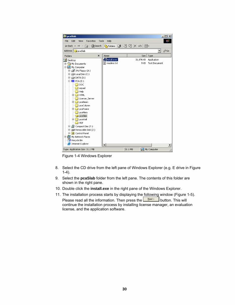
Figure 1-4 Windows Explorer
8. Select the CD drive from the left pane of Windows Explorer (e.g. E drive in Figure
1-4). 9. Select the pcaSlab folder from the left pane. The contents of this folder are
shown in the right pane. 10. Double click the install.exe in the right pane of the Windows Explorer. 11. The installation process starts by displaying the following window (Figure 1-5).
Please read all the information. Then press the button. This will continue the installation process by installing license manager, an evaluation license, and the application software.
30

Figure 1-5 Beginning of the installation
12. The first step of the application installation process is to review the information on the software and the copyrights announcement as shown in Figure 1-6. Please read all the information carefully. Press the
button to confirm that you have read and agreed with it. This will continue the installation. If you do not agree with the license agreement, press the button. This will stop the installation.
Figure 1-6 Copyright announcement
13. Review the Readme file (Figure 1-7), and then press the button to continue.
31

Figure 1-7 Readme File
14. Enter the registration information (Figure 1-8). This information will be shown in
the Help | About dialog box. Press the
button to go to the next step.
Figure 1-8 Enter Registration Information
15. If you continue the installation then the next setup is to decide the directory where pcaSlab is to be installed as shown in Figure 1-9. The default directory is C:\Program Files\PCA\pcaSlab. You may press the
button to locate the directory. If the directory does not exist, the setup program will create it. Press the button to go to the next step.
32

Figure 1-9 Choose Destination Location
16. The next step is to enter the group name as shown in Figure 1-10.Windows will use this name in the Start/Programs menu. Press the
button to go to
the next step.
Figure 1-10 Select Program Manager Group
17. After all the previous steps are completed, press the button as shown in Figure 1-11 to start the installation.
33

Figure 1-11 Start Installation
18. During the installation a window as in Figure 1-12 shows the progress as files are
copied to your hard drive.
Figure 1-12 Installation progress
19. After the installation is completed, a dialog box similar to Figure 1-13 is shown.
Press the button to finish the installation.
34

Figure 1-13 Installation Complete
Purch
The following information is for stand-alone license only. Please refer to t ick Start Guide in the License Server directory on CD regarding the procedures to install networking license.
Lic
ited time of 15 days. ware lice
ill no longer have restrictions limiting the time of operation.
Evahis is the default mode of the license. In this licensing scheme, users are granted
licensed s
asing and Licensing Process
he License server Qu
ensing Model By default, each pcaStructurePoint software application comes in an Evaluation mode. This means that initially our products can be used for a limIf the user decides to purchase the soft nse, and completes the purchase, pcaStructurePoint will provide a License Code. By entering this code, user will activate the software license. Once the software license is activated the application w
luation mode Tlimited rights to use our full-featured software. The only visible difference between theevaluation version and the version is an additional start-up dialog box ashown in Figure 1-14. It gives a choice of buying the software, entering the activation code or running the application in the evaluation mode by pressing the bpcaStructu
utton. Evaluation mode is available for a limited time only. By default, rePoint software applications come with 15 days. That means, from the
he software for the next 15 days. After this nse, or uninstall the application.
day of installation, a user can evaluate ttime, user will either obtain a Lice Note: Any tampering with system clock or evaluation license file will render the software useless.
35

Figure 1-14 Start-up Dialog Box
w to Purchase You may purchase the license on-line on our web site at
Howww.pcaStructurePoint.com
or by calling our Sales Department at 847-972-9024. To buy on-line you may press BUY NOW button which will run your default web browser and open the product web page where you will be able to complete the transaction.
Licensing Activation After the purchase is completed, pcaStructurePoint will generate a unique Activation Code based on the product ID and the locking code, which is derived from the unique hardware-id of the user’s computer. Each License is associated with the particular PC in which user has installed the pcaStructurePoint software. This implies that the activation-code will not work on any other PC. You can transfer the license to another PC by contacting pcaStructurePoint for the transfer procedures.
To activate the license press the button in the start-up dialog box. This will bring a window as in Figure 1-15, which shows three license activation methods.
36

Figure 1-15 License activation methods If you have already received the license code you may choose ENTER LICENCE CODE and then press the button. A window (Figure 1-16) will pop up where you will nse code. However, in order to avoid mistyping we advise to use copy and paste feature instead of typing the code.
be able to type in the lice
Figure 1-16 Enter license code
The license code can also be extracted from a file. To do that press the button and open the file in which the license code is stored using the open window (Figure 1-17).
37

Figure 1-17 Open activation file If the entered code is correct the license will be activated and window as in Figure 1-18 will show. When you press the button the license activation will be completed.
Figure 1-18 Activation completion If you do not have the license code you may chose either TELEPHONE or E-MAIL method (Figure 1-15) whichever is more convenient for you. Please note that for E-MAIL method you need to have the Internet connection and a default mailer configured in your system.
Activation by Phone If the telephone method was chosen to activate the license the following screen appears (Figure 1-19). It shows the product ID and the Locking Code. This
38

information is needed when you makeobtain the license. You will be asked t
a phone call at 847-966-4357 (HELP) to o provide information about yourself in order to
ased the license. verify that you have purch
Figure 1-19 Activation by phone When your information is verified, the license code will be generated and provided to you by an email. When you receive the code type it or copy-paste it in the LICENCE CODE edit box and press the button. If the entered code is correct, the license will be activated and window as in Figure 1-18 will show. When you press the
button the license activation will be completed.
If the e-mail method was chosen to activate the license a screen (Figure 1-20) will show prompting you to provide information about yourself. When you type in all the
Activation by e-mail
information press the button and it will be automatically e-mailed to us together with the product ID and the Locking Code. After the information is verified the license code will be generated and e-mailed back to you.
39

Figure 1-20 Activation by
After you receive it you may enter it by pressing the button in the start up dialog box (Figure 1-14) and choosing ENTER LICENCE CODE option. If the entered code is correct, the license will be activated and window as in Figure 1-18 will show. When you press the button the license activation will be completed. If you experience any problems registering or licensing the software, contact our Technical Support team.
40

Run
1. Windows 95, 98, NT, 2000:
Select the
ning the Program
To execute pcaSlab from within Windows:
button from the lower left corner of the screen then follow the path of Programs/P
2. Windows XP:
Select the
CA Programs/pcaSlab/.
button from the lower left corner of the screen then follow the
Rem
our computer:
1. Click
path of All Programs/PCA Programs/pcaSlab/. 3. Select the "pcaSlab" icon.
oving the Program
To remove the program from y
button (Windows 95, 98, NT, 2000) or button (Windows XP) on the lower left corner of the screen.
2. In Windows 95, 98, NT, 2000, select Programs/PCA Programs/pcaSlab/; In Windows XP, select All Programs/PCA Programs/pcaSlab/.
install pcaSlab. steps shown by the un-installation wizard to remove the program.
3. Select Un4. Follow the
41

Ch. 2 Method of Solution Method of Solution
The user s made by the program during the design stage. Th strip widths, reinforcement selection,
Geometric Consistency Checks
istent system. The dimensions of the slabs, drops and column capitals are hecked and modified to produce a legitimate system.
Geo
s for the drop panel dimensions, ffle slab rib dimensions and slab
am depths meet the applicable code values.
Slab Dim
less than one-half the column dimension in the direction of analysis (c1), or less than the lateral extension of the transverse beam into the cantilever, the cantilever length will be increased to the larger of these two lengths. If the slab width is less than one-half the column dimension transverse to the direction of analysis (c2), or less than one-half the longitudinal beam width,larger of these two widths.
Drop Panel Dimensions
If the drop panel lengths extend beyond the end of the slab cantilevers, the drop panel lengths will be reduced so that they extend only to the cantilever tip. The drop panel edges will be shifted forward or backward in the transverse direction when the slab strip width on either side of the column is less than one-half the drop panel width.
should be aware of the assumptionese include details regarding loading,
deflection computations, material quantities, etc.
The pcaSlab program provides geometric checks to avoid an analysis with an inconsc
metric Code Checks
Prior to an analysis, pcaSlab checks that the input valuecolumn capital dimensions, T-beam flange widths, waand be
ensions
If the slab cantilever length is
the slab width will be increased to the
42

Figure 2-1 Valid drop dimensions
Figure 2-2 Excess drop depth
A valid drop must extend in each direction at least one-sixth the center-to-center span length in that direction (Figure 2-1) and have a drop depth below the slab of at least one-quarter the input slab depth. ACI slabs that contain valid drops are allowed a 10%
43

decrease in minimum slab depth1. The drop depth of an invalid drop wthe calculation of the depth used to reduce the amount of reinforcemen
2
ill not be used in t required at a
n , and will not be used in the calculation of moment of inertia for deflection omputations.
s greater than one-quarter the distance from the edge of the drop anel to the face of the column (x) the excess depth exceeding ¼x will not be considered
The input drop dimensions will be used for self-weight computations, when computing slab stiffness and to determiaround a column.
Column Capital Dimensions
If a colu less than 1, the extension will be limited to the capital depth. The upper limit for the depth/extension ratio is 50. If, by
rawing lines extending the column capital through the drop or beam to the underside of the slab, the column capital extension falls outside the edge of the drop or beam at the
n stiffness.
columc
If the valid drop depth ipin the calculation of the effective depth used to reduce the amount of reinforcement required at a column (Figure 2-2).3
ne moments and shears when computing punching shear
mn capital contains a depth/extension ratio
d
slab soffit, the extension will be modified such that these lines extend only up to the edgeof the drop or beam at the slab soffit (Figure 2-3). The modified column capital dimensions will be used when computing colum
Figure 2-3 Maximum capital width
ACI 318-99, 9.5.3.2; ACI 318-02, 9.5.3.2
-99, 13.3.7; ACI 318-02, 13.3.7 3 ACI 318-99, 13.3.7.3; ACI 318-02, 13.3.7.3; CSA A23.3-94, 13.11.6
1
2 ACI 318
44

Minimum Slab Thickness of Flat Plate, Flat Slab and Beam-Supported Slab Systems
or ACI 318 Code, the minimum thickness of slabs with or without interior beams
Fspanning between supports and having a ratio of long to short span not exceeding 2 is:4
( ) 0.20.2 000,200n
≤α<⎠⎝= Eq. 2-1 2.0536
f8.0l
h mm
y
−αβ+
⎟⎟⎞
⎜⎜⎛
+
But not
less than
0.2 936
000,2008.0ln ⎟⎟
⎠⎜⎜⎝
+fy ⎞⎛
h m >αβ+
= Eq. 2-2
or CSA A23.3-94
F
0.2taken 430 mβα+
1000h m
n
s ≤α⎟⎠
⎜⎝≥ Eq. 2-3
Where
r spans in long to short direction
fy = yield stress of reinforcing steel
f6.0l y ⎟
⎞⎜⎛
+
ln = clear span in the direction of analysis
β = ratio of the clea
4 ACI 318-99, 9.5.3.3; ACI 318-02, 9.5.3.3; CSA-A23.3-94, 13.3.5
45

αm = average value of α, the ratio of flexural stiffness of a beam section to the flexural stiffness of a width of sla terally by centerlines of adjacent panels on either side of the beam, for all beams supporting the edges of a slab panel.
For the design of ACI slabs without beams (α ≤0.2) spanning between supports the minimum thic fo le bs that contain valid drops, Table 9.5(c) reduces the minimum thickness by approximately 10%.5 (See Figure 2-1).
he minimum thickness in a span that contains a discontinuous edge will be increased by 6
rior edge.
ss is:
a) For flat plates and slabs with column capitals
b bounded la
mrm to ACI 318 Tabkness shall con 9.5(c). For flat sla
T10%, if the edge beam provided has a stiffness ratio, α, of less than 0.80. The first and last spans are considered to contain a discontinuous edge as well as a span that contains an exte
For the CSA Standard the minimum thickne
301000
f6.0l y
⎟⎟⎞
⎜⎜⎛
+h
n
s⎠⎝> Eq. 2-4
s with drop panels b) for slab
⎥⎦
⎤⎢⎣
⎡⎟⎞
⎜⎜⎝
⎛ −⎟⎟⎠
⎞⎜⎜⎝
⎛+ sdd
hhh
lx2130 ⎟
⎠
⎟⎠
⎜⎝≥
sn
n
s1000h Eq. 2-5
Where xd/(ln/2) is the smbe taken greater than ln/4 and hd - hs shall not be greater than hs.
For flat plate systems, the minimum allowable thickness can in no case be less than 5.0 . For two-way flat slab systems with drops, described above, the minimum allowable
⎟⎞
⎜⎛
+ yf6.0l
aller of the values determined in the two directions, xd shall not
in
5 ACI 318-99, 9.5.3.2; ACI 318-02, 9.5.3.2 6 ACI 318-99, 9.5.3.3 (d); ACI 318-02, 9.5.3.3 (d)
46

thickness can in no case be less than 4.0 in.7 For supported slab systems supportbeams with an α
ed by
A messagwhere the depth does not meet or exceed code requirements.
Mini
he minimum slab thickness allowed for waffle slabs is one-twelfth the clear rib spacing, or 2 in.9
A message will be printed with the output showing the required slab depth for the system if the depth does not meet o ed code requirements.
Waffle Rib Dimensions
Waffle slab rib dimensions will be considered valid if the rib width is at least 4 in. (or 100 mm), the depth is no more than 3-1/2 tim cing between ribs does not exceed t, the ACI code
ermits the nominal concrete shear strength, Vc, to be increased by 10%.10
m greater than or equal to 2.0, the minimum allowable thickness can in no case be less than 3.5 in.8
e will be printed with the output showing the required slab depth for any span
mum Thickness for Waffle Slab Systems
T
r exce
es the rib width, and the clear spa 30 in. (or 750 mm) (Figure 2-4). When valid ribs exis
p
ACI 318-99, 9.5.3.2; ACI 318-02, 9.5.3.2
8 ACI 318-99, 9.5.3.3; ACI 318-02, 9.5.3.3 9 ACI 318-99, 8.11.6.1; ACI 318-02, 8.11.6.1 10 ACI 318-99, 8.11.8; ACI 318-02, 8.11.8;
7
47

h
30 in.b 4 in.
3.5b
Figure 2-4 Valid rib dimensions
Special Considerations for Waffle Slabs
lysis and design, pcaSlab replaces the waffle with solid slabs of quivalent moment of inertia, weight, and punching shear resistance.
used to compute the system self-eight. This thickness, hw, is given by:
For the purposes of anae
The equivalent thickness based on system weight isw
mod
modw A
Vh = Eq. 2-6
Vmod = the volume of one waffle module.
le module.
s.
MI
Where
Amod = the plan area of one waff
The equivalent thickness based on moment of inertia is used to compute slab stiffnesThe ribs spanning in the transverse direction are not considered in the stiffness computations. This thickness, h , is given by:
48

31
ribI12 ⎟⎞
⎜⎛
ribMI b
h ⎟⎠
⎜⎝
= Eq. 2-7
lines of ribs.
brib = the center-to-center distance of two ribs (clear rib spacing plus rib width).
The drop depth for waffle slab sy rib depth. The equivalent drop epth based on moment of inertia, dMI, is given by:
Eq. 2-8
Where
hrib = rib depth below slab.
hMI = equivalent slab thickness based on moment of inertia.
A drop depth entered for a waffle slab system other than 0 will be added to dMV, thus extending below the ribs.
he equivalent thickness based on shear area is used to compute the area of concrete the drop. The equivalent slab thickness, hV,
Where
Irib = moment of inertia of one waffle section between center
stems is set equal to the d
ribMIMI hhd +=
Tsection resisting shear transfer, Ac aroundused to compute Ac, is given by:
infrerib
v dbAh += Eq. 2-9
rib
Where:
A = the entire rib area below the slab plus the slab thickness minus the distance
idth).
ribto the reinforcement centroid, dreinf, within the rib width, (i.e., the slab depth between the ribs is not considered as contributing to shear resistance.)
brib = the center-to-center distance of two ribs (clear rib spacing plus rib w
49

dreinf = the distance to reinforcement centriod from the slab top at the support.
Mate
the concrete density and compressive strength of the members, default the other concrete properties are determined. The slab, column, and beam
embers may have different concrete properties.
e
rial Properties
By enteringvalues for m
The density of concrete is used to determine the type of concrete, modulus of elasticity, and self-weight.
For the ACI 318 Code, the concrete type is used to determine the default value of fct, theaverage split tensile strength of concrete. The concrete type is determined in accordancwith Table 2-1.
Note: The CSA Standard does not use fct
Density (w)
pcf kg/m3 Type
w ≥ 130 w ≥ 2000 Normal
105 < w < 130 1700 < w < 2000 Sand-Lightweight
w ≤ 105 w ≤ 1700 All-Lightweight
Table 2-1 - Default Concrete Types
Once the compressive strength of concrete f´c is input, various parameters are set to their default values.
The modulus of elasticity is computed as:11
'c
5.1c fw33E = Eq. 2-10
Where
11 ACI 318-99, 8.5.1; ACI 318-02, 8.5.1; CSA-A23.3-94, 8.6.2.2
50

w = the density of the concrete.
For CSA A23.3
( )5.1
cc 2300E
⎠⎝= . 2-11
Where
γ = the unit weight of concrete.
The square root of f´c is limited to for the computation of shear strength provided by concrete, Vc, and development lengths.12
' 6900f3300 ⎟⎞
⎜⎛ γ
+ Eq
'cct f7.6f = Eq. 2-12
Eq. 2-10 and Eq. 2-12 are used internally and cannot be modified.
The average split tensile strength is used to compute the modulus of rupture and reinforcement development lengths. For normal weight concrete, the default value of fct used by pcaSlab is set equal to:13
'cct f7.6f = Eq. 2-13
In no case will fct/6.7 exceed 100 psi. The value fct will be modified according to the concrete type. Table 2-2 shows the default values for fct for different concrete types. No interpolation is performed for partial sand replacement.
12 ACI 318-99, 11.1.2; ACI 318-02, 11.1.2 13 ACI 318-99, 9.5.2.3; ACI 318-02, 9.5.2.3
51

Type fct
Normal 'cf7.6
Sand-Lightweight 'cf7.6 (0.85)
All-Lightweight 'cf7.6 (0.75)
Table 2-2 Default Average Splitting Tensile Strength
The modulus of rupture is used to determine the cracking moment when computing the effective moment of inertia for deflection computations. The default value of fr, modulus of rupture, is set equal to:
For ACI 318
Eq. 2-14
If fct is that given in Eq. 2-13, Eq. 2-14 is equal to:14
ctr f12.1f =
'cr f5.7f = Eq. 2-15
For CSA A23.3
'cr f5.7f = Eq. 2-16
for beams and columns and
2f6.0
f'c
r = Eq. 2-17
for slabs.
14 ACI 318-99, 9.5.2.3; ACI 318-02, 9.5.2.3; CSA A23.3-94, 8.6.4 & 13.3.6
52

There is no limit imposed on fr. Entering a large value of fr will produce deflections based on gross properties, (i.e., uncracked sections).
reinforcement yield strength, fy, and shear rcement yield strength, fyv, if applicable, are set equal to 60 ksi (413 MPa) for ACI
nd 400 MPa for CSA.
The Equivalent Frame Method
The equivalent frame method, as described in the Code,15 is used by pcaSlab for both analysis and design.
ecifies procedures for the analysis and design of slab systems reinforced for n more than one direction, with or without beams between the supports. A two-
way sla ing beams, columns, and walls may be desig
pcaSla analysis. It should be noted that this methodUnivers s or on de
of the building. Horizontal
rs for each frame are formed by slab strips as shown in Figure 2-5. For vertical loads, each story (floor and/or roof) may be analyzed separately with the supporting columns
The default values for the longitudinalreinfoa
The Code spflexure i
b16 system, including the slab and its supportned by either of the following procedures:
The Direct Design Method The Equivalent Frame Method
b uses the Equivalent Frame Method of is based on extensive analytical and experimental studies conducted at the ity of Illinois. Note also that there are no restrictions on the number of slab spanad-to-live load ratios in this method of analysis.
The first step in the frame analysis is to divide the three-dimensional building into a seriesof two-dimensional frames extending to the full heightmembe
being considered fixed at their remote ends. (Figure 2-6).
15 ACI 318-99, Chapter 13; ACI 318-02, Chapter 13; CSA A23.3-94, Clause 13 16 Implies a slab supported by isolated supports which permits the slab to deflect in two orthogonal directions.
53

Figure 2-5 Design strips
Figure 2-6 Analytical model for vertical loads for a typical story
54

Stiffness Characteristics
The stiffness factors for the horizontal members (the slab beams) and the vertical members (the equivalent columns) are determined using segmental approach.
Slab Beams
The moment of inertia of the slab beam elements between the faces of the columns (or column capitals) is based on the uncracked section of the concrete including beams or drop panels. The moment of inertia from the face of the column (or capital) to the centerline of the column (or capital) is considered finite and is dependent on the transverse dimensions of the panel and support. This reduced stiffness (as compared to the infinite stiffness assumed in previous codes) is intended to soften the slab at the joint to account for the flexibility of the slab away from the support. This is consistent with provisions of the Code.17
Figure 2-7 shows the changes in stiffness between a slab, and a drop panel, and a column (or capital).
olumns
The computation of the column s ted as it utilizes the concept of an equivalent column. Theoretical slab studies have shown that the positive moment in a slab may increase under pattern loads, even if rigid columns are used, because of the flexibility of the slab away from the column. However, if a two-dimensional frame analysis is applied to a structure with rigid columns, pattern loads will have little effect. To account for this difference in behavior between slab structures and frames, the equivalent column torsional member, as shown in Figure 2-8, runs transverse to the direction in which the moments are being determined. The transverse slab beam can rotate even though the column may be infinitely stiff, thus permitting moment distribution between adjacent panels. It is seen that the stiffness of the equivalent column is affected by both the flexural stiffness of the columns and the torsional stiffness of the slabs or beams framing into the columns. Note that the method of computation of column stiffness is in accordance with the requirements of the Code18 Figure 2-9 shows a schematic representation of the stiffness of typical columns.
The column stiffness is based on the column height, lc, measured from mid-depth of the slab above, to the mid-depth of the slab below. pcaSlab calculates the stiffness of the column below the design slab, taking into account the design slab system at its top end.
C
tiffness is more complica
17 ACI 318-99, 13.7.3; ACI 318-02, 13.7.3; CSA-A23.3-94, 13.9.2.3 18 ACI 318-99, 13.7.4; ACI 318-02, 13.7.4; CSA-A23.3-94, 13.9
55

pcaSlab calculates the stiffness of the column above the design slab taking only the slab depth into account at its top end; column capitals, beams, or drops are ignored.
The computation simplifying ns. The first step is to assume dimensions of the transverse torsional slab-
eam members. Assumptions for dimensions of typical torsional members are shown in Figure 2-10.
of the torsional stiffness of the member requires severalassumptiob
56

Figure 2-7 Sections for calculating slab-beam stiffness, Ksb
57

continued Figure 2-7
58

Figure 2-8 T
The stiff ber is given by the following expression:19
he equivalent column
ness, Kt of the torsional mem
∑= 3CS
tCE9K
⎟⎜2
Eq. 2-18
Where
ticity for slab concrete.
C = cross-sectional constant defining torsional properties; see Eq. 2-19. It is a conservatively low approximation of the torsional rigidity of rectangular sections
⎟⎞
⎜⎛− 2c1l
⎠⎝ 2l
Ecs = modulus of elas
19 ACI 318-99, 13.7.5; ACI 318-02, 13.7.5; CSA-A23.3-94, Eq. 13.13
59

when assuming elastic behavior. For the CSA Standard l2 is taken as the smaller of l or l .
c = size of rectangular column or capital measured transverse to the direction in being determined.
pan transverse to l1, measured on each side of the l2 is taken as the smaller of l2 or l1.
The consta ction by dividing it into separate rectangular parts an ing summation:20
2 1
2which moments are
l2 = For ACI 318 length of scolumn. For CSA A23.3-94
nt C is evaluated for the cross sed by carrying out the follow
3y63.01C ∑ ⎟⎟
⎠⎜⎜⎝−=
yx3⎞ Eq. 2-19
Where
x = Short overall dimension of the rectangular part of a cross section
y = Long overall dimension of the rectangular part of a cross section.
s a result of Eq. 2-19, walls21 running the full width of a slab (c2 = l2) cannot be modeled by the Equivalent Frame Method.
When beams frame into the column in the direction of analysis, the value of Kt as comput ratio of the moment of inertia of the slab with the beam (I of the slab without the beam (Is), as shown:
x⎛
A
ed in Eq. 2-18 is multiplied by thesb) to the moment of inertia
sIsb
ttaIKK = Eq. 2-20
With ref 8, Is is computed from part A (slab without beam), whereas Isb is computed f s A and B (slab with beam).
erence to Figure 2-rom both part
20 CSA-A23.3-94, Eq. 13-14 21 Instead walls can be modeled as long supports less than the full design width of the slab. To obtain a uniform distribution of the end moment along the column and middle strips, the width of the wall must be greater than 75% of the design strip.
60

Knowing the column stiffness, Kc, and the stiffness of the attached torsional member, Kt, the stiffness of the equivalent column, Kec, is computed from the equation:
tata
cbct
cbctec KKK
+=
KK1
KK
++
+Eq. 2-21
Where
Kct, Kcb = top and bottom column stiffness,
Kta = the stiffness of the left and right torsional member.
61
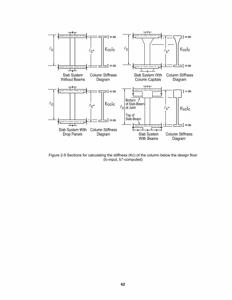
Figure 2-9 Sections for calculating the stiffness (Kc) of the column below the design floor (lc-input, lc*-computed)
62

C = 1-0.63x1y1
x13y13
+ 1- 0.63x2y2
x23y23
Figure Section of the attac bers
2-10 hed torsional mem
63

Loading
Frame Method. Results of gravity load and teral load analyses may be combined, however, the effects of cracking and
rcement on stiffness must be accounted for in the lateral load analysis.
Self-Weight
The self-weight of the t t ll pcaSlab. The weights of the slabs, drops, and longitudinal and t e m e sidered in the self weight
for length equal to one-half c1, the column dimension in the direction of analysis. This will
uce slightly less self-weight than actually present for beams wider than c2, the
Sup
ll superimposed vertical loading is considered to act over the entire transverse width of e
y these loads in addition to the portion of the slab moments assigned to the beam.
Lateral Loading
For late unit for the entire height of the building (Figure 2-11). Computer programs, such as PCA-Frame, are available for perform -beam elementmade fo
om such an analysis may then be input into the equivalent frame model using pcaSlab determine the appropriate design moments under combined vertical and lateral loads.
All applied loads are input as unfactored loads. There are no limitations imposed on the ratio of dead to live loads in the Equivalentlareinfo
floor system is compuransvers
ed in bea
ernas ar
y by con
computations. Only the concrete weight is considered, the reinforcement weight is ignored. The weight of longitudinal beams is ignored starting at the column centerline, aprodcolumn’s transverse dimension.
erimposed Loading
Athe slab. For slab systems with beams, loads supported directly by the beam (such as thweight of the beam stem or a wall supported directly by the beams) are also assumed to be distributed over the entire transverse width of the strip. An additional analysis may be required, with the beam section designed to carr
ral loads, each frame should be analyzed as a
ing such analyses. It should be realized that, for lateral load analysis, slabs may have a reduced stiffness due to cracking as well as other assumptions r the effective slab width used for the lateral analysis. The moments obtained
frto
64

en to
according to the code distribution factors computed for vertical lo
Loading Patterns
ations. or example, the two adjacent spans loaded may produce the maximum shear stress round a column, while the alternate spans loaded may produce the maximum flexural
sed
oading Pattern No. l: All spans loaded with live load (LALL).
s loaded with live load (LEVEN).
oading Pattern No. 4: Two adjacent spans loaded with live load (LSUPP).
reduces the magnitude of live load patterns No.2 through No.4 by a predefined tio. The default live load pattern ratio selected by the program equals 75% as
permitted by the code.22 The user has the ability to select different value for the pattern
Figure 2-11 Analytical model for lateral loads
By default, pcaSlab distributes the effect of lateral load moment, the difference betwethe total load moments, vertical plus lateral, and the vertical only moment envelopes, the column strip and middle strip
ads (see Table 2-3 through Table 2-5 later in this chapter).
The analysis of floor systems requires the consideration of several loading configurFamoments. To cover different loading scenarios pcaSlab generates live load case baon the following load patterns (Figure 2-12):
L
Loading Pattern No. 2: Alternate (odd) spans loaded with live load (LODD).
Loading Pattern No. 3: Alternate (even) span
L
pcaSlabra
22 ACI 318-99, 13.7.6.3; ACI 318-02, 13.7.6.3; CSA-A23.3-94, 13.9.4
65
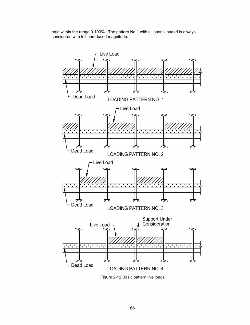
ratio within the range 0-100%. The pattern No.1 with all spans loaded is always considered with full unreduced magnitude.
Figure 2-12 Basic pattern live loads
66

Load Combinations
efining up to 20 load combinations. The user has full control over the ombinations. The program contains predefined (build into the program) default primary
load combinations for the supported codes. These default combinations are created when starting a new project.
For the ACI 318-99 C ive (L), Wind (W) and Earthquake (E) loads considered by the program are:
U8 = 0.75(1.4D + 1.7L + 1.7*1.1E)
1.4D + 1.7*1.1E)
U12 = 0.9D + 1.43E
U13 = 0.9D -- 1.43E
For the ACI 318-02 Code, the default combinations of the Dead (D), Live (L), Wind (W) and Earthquake (E
U1 = 1.4D
U2 = 1.2D + 1.6L
U3 = 1.2D + 1.6L + 0.8W
U4 = 1.2D + 1.6L – 0.8W
U5 = 1.2D + 1.0L + 1.6W
pcaSlab allows dc
ode, the default combinations of the Dead (D), L
U1 = 1.4D + 1.7L
U2 = 0.75(1.4D + 1.7L + 1.7W)
U3 = 0.75(1.4D + 1.7L -- 1.7W)
U4 = 0.75(1.4D + 1.7W)
U5 = 0.75(1.4D -- 1.7W)
U6 = 0.9D + 1.3W
U7 = 0.9D -- 1.3W
U9 = 0.75(1.4D + 1.7L -- 1.7*1.1E)
U10 = 0.75(
U11 = 0.75(1.4D -- 1.7*1.1E)
) loads considered by the program are:
67

U6 = 1.2D + 1.0L – 1.6W
U10 = 1.2D + 1.0L – 1.0W
For the CSA-A23.3 Code, the default combinations of the Dead (D), Live (L), Wind (W)
U1 = 1.25D + 1.5L
U2 = 1.25D + 0.7(1.5L + 1.5W)
U3 = 1.25D + 0.7(1.5L – 1.5W)
U4 = 0.85D + 1.5W
U5 = 0.85D – 1.5W
U6 = 1.0D + 0.5L + 1.0E
U7 = 1.0D + 0.5L – 1.0E
U8 = 1.0D + 1.0E
U9 = 1.0D – 1.0E
Column and Mi
s
are printed as part of the echo of input data.
he strip widths at a support are computed by (see Figure 2-13)
U7 = 0.9D + 1.6W
U8 = 0.9D -- 1.6W
U9 = 1.2D + 1.0L + 1.0W
U11 = 0.9D + 1.0W
U12 = 0.9D -- 1.0W
and Earthquake (E) loads considered by the program are:
ddle Strip Widths
The Code23 defines the width of the column strip on each side of the column centerline abeing one-fourth of the smaller of either the transverse or the longitudinal span. These widths
T
23 ACI 318-99, 13.2.1; ACI 318-02, 13.2.1; CSA-A23.3-94, 13.1
68

Column strip
⎪⎪⎭⎩ ⎭⎩⎭⎩ ++ 1i1i 4242
Middle strip
⎪⎬
⎪⎪
⎪⎨
⎬⎫
⎨⎧
+⎬⎫
⎨⎧
⎭⎩⎭⎩=1r,2ll,2
iiCS l,
lminl,
lmin
4242minW Eq. 2-22 ⎪⎫
⎪⎧
⎬⎫
⎨⎧
+⎬⎫
⎨⎧ lr,21l,2 l,
lminl,
lmin
{ } CS1i,2i,2MS Wl,lminW −= + Eq. 2-23
The strip widths in the span are defined as (see Figure 2-14):
⎭⎬⎫
⎩⎨⎧
+⎭⎬⎫
⎩⎨⎧
=4l,
2l
min4l,
2l
minW 1r,21l,2CS Eq. 2-24
Middle strip
Eq. 2-25
Where
min{a, b} = the smaller of “a” and “b”.
l1 = span length in the direction of analysis
l2 = the total input transverse strip width
l2,1, l2,r = the input transverse strip widths on the left and right of column centerline, respectively
i, i+1 = span left and right of column centerline, respectively.
CS2MS WlW −=
69

Figure 2-13 Strips widths at support
70

Figure 2-14 Strip widths in span
a beam exists
the beam width is greater than the column strip width, Wcs, then
If
bCSCS WWW −= Eq. 2-26
If
( )0W
WWWW CSbMSMS
=CS
−−= Eq. 2-27
Where
For exterior frames, the edge width should be specified to the edge of the slab from the column centerline.
Wb = beam width.
71

ign Moments Des
n at ace
the longitudinal span length, l1, away from the center of the column.24 This imposes a limit on long narrow supports, in order to prevent undue reduction in the
esign moment. For slab systems with transverse beams, the face of a beam is not
pcaSlab considers negative moments for design purposes as those producing tensiothe top of the slab. The negative design moment is taken at a section located at the fof the column, or column capital, but in no case is it considered at a location greater than 0.175 of
dconsidered as the face of support. For end columns with capitals, the moments are taken at the midpoint of the capital extension.25 The column and middle strip moments correspond to the moments assigned to the slab element only.
The column strips are proportioned to resist the portions in percent of interior negative factored moments according to Table 2-3.26
l2/l1 0.5 1.0 2.0
(α1l2/l1) = 0 75 75 75
(α1l2/l1) ≥ 1.0 90 75 45
Table 2-3 - Column Strip P
umn strips are proportioned to resist the portions in percent of exterior negative ctored moments according to Table 2-4.27
ercent of Interior Negative Factored Moments at Supports
The colfa
l2/l1 0.5 1.0 2.0
βt = 0 100 100 100(α1l2/l1) = 0
βt ≥ 2.5 75 75 75
βt = 0 100 100 100(α1l2/l1) ≥ 1.0
βt ≥ 2.5 90 75 45
Table 2-4
- Column Strip Percent of Exterior Negative Factored Moments at Supports
.7.7.1; ACI 318-02, 13.7.7.1; CSA3-A23.3-94, 13.9.5.1
25 ACI 318-99, 13.7.7.2; ACI 318-02, 13.7.7.2; CSA3-A23.3-94, 13.9.5.2 26 ACI 318-99, 13.6.4.1; ACI 318-02, 13.6.4.1; CSA3-A23.3-94, 13.9.5.1 27 ACI 318-99, 13.6.4.2; ACI 318-02, 13.6.4.2
24 ACI 318-99, 13
72

The val
α1 = rati of a width of slab bounded by centerlines of adjacent panels (if any) on each side of the beam in the
irection of analysis. For flat plates, flat slabs, and waffle α1l2/l1 = 0
t = ratio of torsional stiffness of an edge beam section to flexural stiffness of a width of qual to 28
ues α1 in Table 2-3 and Table 2-4 and βt in Table 2-4 are defined as:
o of flexural stiffness of the beam section to flexural stiffness
d
βslab e the span length of the beam, center-to-center of supports; see Eq. 2-28. When no transverse beams are present, βt = 0.
SCS
cbt IE2
CE=β Eq. 2-28
Where
Ecb = modulus of elasticity o
Ecs = modulus of elasticity of slab concrete.
C = cross-sectional constant to define torsional properties; see Eq. 2-19
I = moment of inertia of the gross section of the slab about its centroidal axis.
For intermediate values of (l /l ), (α l /l ) and β the values in Table 2-3 and Table 2-4 are
Percentage of negative factored moment at interior support to be resisted by column
f beam concrete.
s
2 1 1 2 1 tinterpolated using equations Eq. 2-29 and Eq. 2-30.
strip:
⎟⎟⎠⎝⎠⎝ 11 ll
Percentage of negative factored moment at exterior support to be resisted by column strip:
⎞⎜⎜⎛−⎟⎟
⎞⎜⎜⎛ α
+= 221 l1l3075 Eq. 2-29
⎟⎟⎠
⎞⎛⎞⎛ α ll⎜⎜⎝−⎟⎟
⎠⎜⎜⎝
β+β−=1
2
1
21tt l
1l
1210100 Eq. 2-30
e strip width, l2 the negative moment is uniformly distributed across l2.
When a column width, c2, is equal to or greater than 75 percent of th29
28 ACI 318-99, 13.0; ACI 318-02, 13.0; CSA3-A23.3-94, 13.0 29 ACI 318-99, 13.6.5; ACI 318-02, 13.6.5
73

When designing by the CSA A23.3-94 Code, a portion of the total positive or interior negative moment equivalent to:
⎥⎥⎤
⎢⎢⎣
⎡⎟⎟⎞
⎜⎜⎝
⎛+
α2
1
2
1
ll1
Eq. 2-31
⎦⎠
resisted by the beam. For exterior supports the beam is proportioned to resist 100% of
hat portion of the moment not resisted by the beam is resisted by the slab. The inforcement required to resist this moment is distributed evenly across the slab.
or ACI designs the longitudinal beams are proportioned to resist 85 percent of the column stbetween olumn strip moment between 0 and 85.30
utes the effects of lateral ads according to Table 2-3 and Table 2-4.
The middle strips are proportioned to resist the portion of the total is not resisted by the column strips.
s es of the support. The negative design moment is the moment
hich requires the most area of reinforcement to be resisted. The location, left or right of the support, of the maximum moment may vary when systems differ on each side of the support (for example, a system with beamoments for design pucolumn strips are proportioned to resist the portions in percent of positive factored moments according to Table 2-5.31
For ACI designs the column strips are proportioned to resist the portions in percent of factored span according to Table 2-5.31
isthe negative moment.
Tre
Frip moments if α1l2/l1 is equal to or greater than 1.0. For values of α1l2/l1 0 and 1.0, the beam is designed to resist a proportionate percentage of the
c
When lateral loads are present, pcaSlab, by default, distriblo
factored moments that
For de ign purposes, pcaSlab computes the amount of reinforcement for the momentson the left and right sidw
ms on one side only). pcaSlab considers positive rposes as those producing tension at the bottom of the slab. The
vertical load moments along the
30 ACI 318-99, 13.6.5; ACI 318-02, 13.6.5 31 ACI 318-99, 13.6.4.4; ACI 318-02, 13.6.4.4
74

l /l 0.5 1.0 2.0 2 1
(α l /l ) = 0 60 60 60 1 2 1
(α1l2/l1) ≥ 1.0 90 75 45
Table 2-5 - Column Strip Percent of Positive Factored Moments
For intermediate values of (l2/l1) and (α1l2/l1) the values in Table 2-5 are interpolated using as follows: Eq. 2-32
⎟⎠
⎜⎝⎟⎠
⎜⎝ 11 ll
⎟⎞
⎜⎛⎟⎞
⎜⎛ α 221 ll
−+= 5.13060 Eq. 2-32
he middle strips are proportioned to resist the remainder of the total factored moments.
, flat slabs, and waffle slabs, α1l2/l1 = 0.
She
Three types of shear can occur on slab systems: wide beam shear, punching shear, and moment transfer shear. pcaSlab checks wide beam shear at a critical section located at a distance equal to the effective depth away from the face of the supports. The tributary
rea for wide beam shear calculations extends from the critical section to the center of e span. For punching shear including moment transfer shear it is assumed that both
shear act on the same critical section. The critical section for shear is defined in e.32
e 2-15 shows the general punching shear area used by pcaSlab. Note that the l considerations as
explained below.
T
Note, for flat plates
ar Analysis of Slabs
athtypes ofthe Cod
Figurshaded area represents the general case and is modified for specia
32 ACI 318-99, 11.12.1.2; ACI 318-02, 11.12.1.2; CSA-A23.3-94, 13.4.3
75

Figure 2-15 Critical section for shear at column
ment transfer as indicated in Figure erse beams transfer unbalanced
moment tthe slab a
g the point at which punching shear is no longer applicable and beam nate element in shear transfer to the column. In the default
mode of pcaSlab, the program makes no such distinction and computes unbalanced moment transfer stress without regard to anpossible, however, to have pcaSlab distribubeams. Although the depth of the beam is considered in the critical section surfaces, the distances to the critical section are not increased at the intersection with any beams. This
Shallow beams are considered in the unbalanced mo2-15 by areas B1, B2, B3, B4, B5, B6. Ordinarily, transv
o the column through torsion along the beam and not through shear between nd column. However, the Code leaves the transfer method to the engineer’s
judgment concerninshear becomes the domi
y beams framing into the column. It is te the shear and torsion among the framing
approach is conservative. pcaSlab does not compute torsional stresses in the slab. If in the engineer’s judgment this may control, it must be computed manually.
For a circular column or column capital, a square shape with an equivalent area is assumed as shown in Figure 2-16. Critical section area for punching, Ac, is then
multiplied by )d4D2/()dD( +π+π to account for the difference between circular and square critical sections, where D is the diameter of a column or a column capital a“d” is the effective depth of the slab.
nd
76

Figure 2-16 Critical section area for circular column
77

The critical section is considered closed if the a distance greater than or equal to the specifiedefine the distance extended beyond the column face in order to consider the section
sed. The default value for this distance is ten times the slab thickness (10h) as quired by ACI code. If the critical section does not meet the distance requirement it is
CritiFram
concrete slab around a column extends to d treshold value. In pcaSlab the user may
cloreconsidered open.
cal Section for Interior Supports of Interior es
The critical section (Figure 2-17) consists of four vertical surfaces through the slab, located at distances of d/2 beyond the support faces.
Figure 2-17 Interior supports of interior frames
supports of interior frames is always closed. A closed defined in Figure 2-15, resisting shear as indicated by Eq.
-33:
Eq. 2-33
The critical section for interior section will have all its faces2
∑=8
AA =1i
iC
78

If beams frame33 into the column, then the critical section includes the dimensions of the beams (B through B in Figure 2-15).
CritiFram
he critical section for exterior supports of interior frames (Figure 2-18) will be either or A1 and A2 for the last column in Figure 2-15) cantilever in relation to slab thickness. The hen the clear cantilever span, lc, is greater than
r equal to the distance defined by the user beyond the column face (the default value is ms frame into the column, then the critical section includes the contributions
1 6
cal Section for Exterior Supports of Interior es
Tclosed (full A7 and A6 for the first column or open, depending upon the length of thecritical section will be considered closed wo10h). If beafrom the beam dimensions (B1 through B6 in Figure 2-15).
Figure 2-18 Exterior supports of interior frames
CritiFram
cal Section for Interior Supports of Exterior es
33 A beam is considered as framing into the column if the beam is within a face of the column.
79

Figure 2-19 shows the critical section for shear for an interior support of an exterior frame. Note that the section is consideFigure 2-15) and it extends up to the edframe into the column, then the critical section includes the contribution from the beam
ns (B1 through B6 in Figure 2-15). If the exterior cantilever span is greater than ce defined by the user beyond the column face (the default value is
10h), th upport is treated as an interior support of an interior frame.
red as U-shaped (A5 = 0, A8 = 0, B3 = 0, B4 = 0 in ge of the exterior face of the support. If beams
dimensioor equal to the distan
e section is treated as closed, that is, the s
Figure 2-19 Interior supports of exterior frames
Critical Section for Exterior Supports of Exterior Frames
The critical section for an exterior support of an exterior frame will typically be L-shaped (A5 =0, A6 =0, A7 =0, A8 =0, B1 = 0, B3 =0, and B4 = 0 in Figure 2-15).
If the cantilever span lc (in the direction of analysis) greater than or equal to the e default value is 10h), then the
tion, the cantilever span in ansverse direction is greater than or equal to the distance defined by the user beyond
n face (the default value is 10h), the section is treated as closed. If beams
isdistance defined by the user beyond the column face (thsection is treated as a U-shaped interior support. If, in additrthe columframe into the column, then the critical section includes the contributions from the beamdimensions.
80

Computation of Allowable Shear Stress at Critical Section
One-way shear strength of slabs is limited34 to 'cf2 . Two-way shear strength of slabs is
affected by concrete strength, relationship between thickness, loaded area aspect ratio, and shear-to-mconnections.
or the ACI 318-99, ACI 318-02 and CSA A23.3-94 Code, these variables are taken into account in the allowable shear stress Eqs. 2-36 through 2-39. The allowable shear stress
pcaSlab is computed at distances of d/2 around the columns and drops (if applicable) and taken as the smallest of the 3 quantities:35
size of loaded area and slab oment ratio at slab-column
F
used by
'f42v ⎟⎞
⎜⎛
+= cc ⎟⎜ Eq. 2-34 c ⎠⎝ β
'c
0
Sc f
b2v ⎟⎟
⎠⎜⎜⎝
+=d ⎞⎛ α
Eq. 2-35
'cc f4v = Eq. 2-36
αs = a constant dependent of the column location, (40 for an interior 4-sided effective critical area, 30 for an exterior 3-sided critical area, 20 for a corner 2-
the slab tension reinforcement at support.
b = the perimeter of the critical section.
The allo
Where
βc = the ratio of the long to the short side of the column.
sided effective critical area.)
d = distance from the slab bottom to centroid of
0
wable shear stress around drops when waffle slabs are used is computed as:
34 ACI 318-99, 11.3.1.1; ACI 318-02, 11.3.1.1 35 ACI 318-99, 11.12.2.1; ACI 318-02, 11.12.2.1; CSA-A23.3-94, 13.4.4
81

'c
'cc
2.0 vCSA
f2 vACI
φ=
= Eq. 2-37
cc f
Where
= resistance factor for concrete.
For waf arlier in this chapter, the allowable shear stress is
Computation of Factored Shear Force at Critical Section
mputed as the reaction t the centroid of the critical section (e.g., column centerline for interior columns) minus e self-weight and any superimposed surface dead and live load acting within the critical
Computation of Unbalanced Moment at Critical Section
Com
ching shear stress printed by the program is based on the following:37
φ c
fle slab systems with valid ribs defined e increased by 10% for ACI designs.36
The factored shear force Vu on the critical section, is by default coathsection. If the section is considered open, two 45 degree lines are drawn from the column corners to the nearest slab edge (lines AF and DE in Figure 2-19) and the self-weight and superimposed surface dead and live loads acting on the area ADEF are omitted from Vu.
The factored unbalanced moment used for shear transfer, Munbal, by default is computed as the sum of the joint moments to the left and right, taken to the centroidal axis of the critical section.
putation of Shear Stresses at Critical Section
The pun
36 ACI 318-99, 8.11.8; ACI 318-02, 8.11.8 37 ACI 318-99, 11.12.6.2; ACI 318-02, 11.12.6.2; CSA-A23.3-94, 13.4.5
82

c
uu
Vv = A
Eq. 2-38
Vu = factored shear force on the critical section described above
beam if any, resisting shear transfer.
s cal
Where:
Ac = area of concrete, including
Under conditions of combined shear, Vu, and an unbalanced moment, Munbal, γvMunbal iassumed to be transferred by eccentricity of shear about the centroidal axis of the critisection. The shear stresses printed by the program for this condition correspond to:38
c
ABunbalv
c
uAB J
cMV γA
v += Eq. 2-39
cc
Where
CDunbalvuCD J
cMAVv γ
−= Eq. 2-40
Munbal = factored unbalanced moment transferred directly from slab to column, as
f
Eq. 2-41
cAB, cCD = distance from centroid of critical section to face of section where stress is being omputed.
described above.
γv = fraction of unbalanced moment considered transferred by the eccentricity oshear about the centroid of the assumed critical section.39
)1( fv γ−=γ
c
Where
38 ACI 318-99, 11.12.6.2; ACI 318-02, 11.12.6.2; CSA-A23.3-94, 13.4.5.5 39 ACI 318-99, 11.12.6.2; ACI 318-02, 11.12.6.2; CSA-A23.3-94, Eq, 13-8
83

21f b/b)3/2(1
1+
=γ Eq. 2-42
Jc = property of the assumed critical section analogous to polar moment of inertia
b1 = width of critical section in the direction of analysis
calculates vu as the absolute maximum of vAB and vCD. Local effects of
Shear Resistance at Corner Columns
For CSA A23.3-94 Code the program performs onevicinity of corner columns. A critical shear section is located d/2 from the column corner. The minimum length section is selected using an optimization algorithm which analyzes
the cantilevered portion is considered by a length not to exceed effective slab thickness d. For slabs with edge beams or drop panels the check
Shear A
When loreinforcReinforc rogram output provides values of Vu, Vc, and Av/s for elected segment locations of each span. Segment lengths are chosen not to exceed the
n depth. The beginning of first segment and the end of last segment ight support respectively.
m depth, away from e column face at both the left and the right ends of the beam. However, if concentrated
loads are present within distance “d” from the column face, critical section is selected at
Vu is computed from the load acting over the entire wimakes no distinction between shallow beams (α1l2/l1 (α1l2/l1 greater than 1).
b2 = width of the critical section in the transverse direction.
pcaSlabconcentrated loads are not computed by pcaSlab and must be calculated manually.
-way shear resistance check in the
sections at different angles. The extension to
including the contribution of these components should be preformed manually.
nalysis of Longitudinal Beams
ngitudinal beams are present in a span, pcaSlab will compute the shear ement requirements for the beams. Table “Longitudinal Beam Shear ement Required” in the p
sbeam sectiocorrespond to the locations of critical sections on the left and rThe critical sections are located at a distance “d”, the effective beath
the column face.
dth of the design strip. The program less than 1) and deeper beams
84

318 Code the shear strength provided by concrete, Vc, is computed by:40For ACI
dbf2V w'cc = Eq. 2-43
In CSA design, for beams without minimum stirrup reinforcement and greater than 300mm deep, vc is calculated from the
following equation:
dbf10.0dbf260w
'ccw
'ccc λϕ≥λϕ⎟
⎞⎜⎛= Eq. 2-44
d1000 ⎠⎝ +
V
Whe u ϕ> , the beam must be provided with at least a minimum shear reinforce
n 2/VV c
ment of:41
yv
wv
fs= Eq. 2-45
b50A
Av = area of two legs of stirrups
t must be provided so that:
Where
s = stirrups spacing
bw = longitudinal beam width
fyv = yield strength of the shear reinforcement
When cu VV ϕ> , shear reinforcemen
dfVV
sA
yv
cuv
ϕϕ−
= Eq. 2-46
Where
40 ACI 318-99, 11.3.1.1; ACI 318-02, 11.3.1.1; CSA-A23.3-94, 11.3.5.1 41 ACI 318-99, 11.5.5.2; ACI 318-02, 11.5.5.2; CSA-A23.3-94, 11.2.8.4
85

Vu = factored shear force at the section being considered
d = effective depth of the beam at the same location
For the ACI 318-99 Code the strength reduction factor for shear calculations is specified as φ=0.85. For the ACI 318-02 Code the strength reduction factor for shear calculations is equal φ=0.75.
When Vu exceeds φ5Vc, the beam section dimensions must be increased or a higher
concrete strength must be provided.42 When dbf10V w'cu ϕ≤ , the spacing is
computed as:
sbv
A
sA1s = Eq. 2-47
Where
Asb = total bar area of the two legged stirrup.
The maximum stirrup spacing must not exceed d/2 nor 24 in. when dbf6V w'cu ϕ≤ .
When dbf6V w'cu ϕ>
43 When
, the maximum stirrup spacing must be reduced by half, to d/4
or 12 in. dbf10V w'cu ϕ> ,
ete strength must be p the beam section dimensions must be increased
or a higher concr rovided.
ns the slab and beam share of ne-way shear according to the following ratios:
Eq. 2-48
When ribs are present (waffle) the program proportions the slab and beam share of one-ay shear according to the following ratios of cross-section areas:
When no ribs are present (waffle) the program proportioo
l/l1,l/l α−α 121121
w
42 ACI 318-99, 11.5.6.9; ACI 318-02, 11.5.6.9; CSA-A23.3-94, 11.3.4 43 ACI 318-99, 11.5.4; ACI 318-02, 11.5.4; CSA-A23.3-94, 11.2.11
86

beamribs
beam
ribs
ribs ,A +
Eq. 2-49 beam AA
AA
A+
Area of Reinforcement
he required area of reinforcement (top and bottom) based on the values of bending moment envelope within the clear span. For rectangular sections with
o compression reinforcement, the design flexural strength of the column strip, middle ent:
The program calculates t
nstrip and beam must equal the factored design mom
⎟⎟ Eq. 2-50 ⎠
⎞⎜⎜⎝
⎛−ϕ=
b)f85.0(2fA
dAfM 'c
yssyu
The reinforcement can therefore be computed from:
⎟⎟⎠
⎜⎜⎝ ϕ
−−=bf85.0
ddf
A 'uc
s Eq. 2-51 ⎞⎛ M2
c
2
y
bf85.0 '
For CSA A23.3-94
⎟⎟⎠
⎞⎛ φ fA⎜⎜⎝ ϕα
−φ=bf(2
dAfM 'cc1
ysssysr Eq. 2-52
ent centroid. The column strip
depth may include all or part of the drop panel depth. The drop depth will not be included in the effethe center-to-center span length in all directions, or when the drop depth below the slab is
ss than one-quarter the slab depth. If the drop does extend at least one-sixth the -center span length and the drop depth is greater than one-quarter the distance edge of the drop panel to the face of the column or column capital, the excess
depth wthe colureinforc
For the ions is specified as φ=0.9 nsion-controlled sections (εt ≥ 0.005) is equal φ=0.90. For transition sections (0.002 < εt < 0.005) the strength reduction factor is specified by the formula:
The effective depth of the section is taken as the overall section depth minus the distancefrom the extreme tension fiber to the tension reinforcem
ctive depth of the column strip when the drop does not extend at least one-sixth
lecenter-tofrom the
ill not be included in the column strip effective depth. If the drop width is less than mn strip width, the drop width will be used in the computation of the required ement.
ACI 318-99 Code the strength reduction factor for flexure calculat0.44 For the ACI 318-02 Code the strength reduction factor for te
44 ACI 318-99, 9.3.2
87

Eq. 2-53
trolled ections (εt < 0.002) as equal φ=0.65. The reduction factors for transition or compression
olled sections have application primarily in investigation mode of the program. In lculations assuming tension controlled section t (if enabled).
t8348.0 ε⋅+=φ
ACI 318-02 Code specifies the strength reduction factor for compression conscontrdesign mode the program performs the caor section with compressive reinforcemen
The ACI 318-99 Code requires keeping the steel ratio below 75 percent bρ , where:45
yy
'c
1b f8787
ff85.0
+β=ρ Eq. 2-54
Where
1β = 0.85 for ksi4f 'c ≤
= 0.65 for
= for
For CSA code the value of ρ is calculated as follows:
ksi8f 'c ≥
'cf05.005.1 − ksi8fksi4 '
c <<
b
yy
'c
11b700f
βα=ρf700f +
Eq. 2-55
lue of net nsile strain (εt ≥ 0.005) 46 (tensioned controlled section). From this condition the
quivalent maximum reinforcement ratio for rectangular section can be written as:
Where
67.0f 0015.085.0α 'c1 ≥−=
67.0f 0025.097.0β 'c1 ≥−=
The ACI 318-02 Code controls the amount of reinforcement by limiting the vatee
ACI 318-99, 8.4.3; CSA A23.3-94, 10.5.2 ACI 318-02, 10.3.5
45
46
88

y
'c1
max ff85.0
005.0003.0003.0 β+
=ρ Eq. 2-56
If the calculated reinforcement exceeds the maximum allowed, a message will appear inthe output. In such c
ases, it is recommended that the engineer review the slab thickness
ensure a more satisfactory design. If compression reinforcement calculations are nabled, pcaSlab will attempt to add compression reinforcement to the section. The
program is capable to design compressive reinforcement for any design strip (column, middle, and beam) including also unbalanced moment strip.
The amount of reinforcement provided will not be less than the code prescribed minimum. For the ACI 318 Code, the minimum ratio of reinforcement area to the gross sectional area of the slab strip using Grade 60 reinforcement is taken as 0.0018. When reinforcement yield strength exceeds 60 ksi, the minimum ratio is set to 0.0018 x 60/fy. For reinforcement with yield strength less than 60 ksi, the minimum ratio is set to 0.0020. In no case will this ratio be less than 0.0014 47 (See Table 2-6). The CSA Standard requires a minimum ratio of slab reinforcement area to gross sectional area of the slab strip equal to 0.002 for all grades of reinforcement.
fy (ksi) As/Ag
toe
< 60 0.0020
≥ 60 0014.0f
600018.0
y
≥×
Table 2-6 - Minimum Ratios of Reinforcement to Gross Concrete Area
According to ACI code for beams and positive moment regions of waffle slabs, minimum reinforcement provided will not be less than:48
dbf
f3A w
y
'c
min,s = Eq. 2-57
and not less than 200bwd/fy
Similar equation prescribed by CSA code has the form:
47 ACI 318-99, 7.12.2.1; ACI 318-02, 7.12.2.1; CSA A23.3-94, 7.8 48 ACI 318-99, 10.5.1; ACI 318-02, 10.5.1
89

hbf2.0
A'c=
f wy
min,s Eq. 2-58
calculating required amounts of negative support steel for CSA A23.3-94 Code, the gram performs the adjustment for banded and distributed reinforcement. The code
requires concentrating one-third of the negative reinforcement at interior supports in the hs from the sides of the columns. At exterior supports the total
negative reinforcement is placed in the band region. The remaining portion of the egative reinforcement needs to be placed in the distributed strip. The reinforcement in
Reinforcement Selection
ing of reinforcement considered in pcaSlab is the Code rescribed minima for both slabs and beams of one bar diameter, db, or 1 in.49 The user ay select clear spacing greater than the default value.
For ACI 318 the maximum spacing of reinforcement is kept at two times the slab thickness.50
When calculating negative support reinforcement for CSA A23.3-94 the program assumes that banded reinforceme spaced at a maximum of 1.5 hs while distributed
of 3 hs.
, the number of bars required to satisfy these limitations is computed and the iteration process terminates.
reinforcement is provided if sufficient beam width is not available. caSlab assumes a 1.5 in. cover to stirrup for width calculations. pcaSlab also assumes
that the longitudinal bar makes contact at the middle of the stirrup bend where the
Inpro
band region extending 1.5
nbanded and distributed strip is also checked for compliance with the minimum reinforcement requirement.
The default minimum clear spacpm
nt isreinforcement is spaced at a maximum
An iterative process is performed to determine the number of bars and bar size. The initial number of bars is determined by dividing the total reinforcement area required, As, by the area of one bar, Asb, of the input minimum bar size. Next, the spacing is determined. If the minimum spacing limitations are violated, the bar size is increased and the iterative process continues until all bars sizes have been checked. If the maximum spacing limitations are not met
For beams, layeredp
49 ACI 318-99, 7.6.1; ACI 318-02, 7.6.1 50 ACI 318-99, 13.3.2; ACI 318-02, 13.3.2
90

minimum inside diameter of the bend is 4db. Therefore, an additional width is added tothe cover for longitudinal bars less than #14 (an SI N-45) in size (Figure 2-20 – Figure 2-21). This additional width due to the bend, w
bend, is equal to:
⎟⎠⎞⎛ dw b
ben ⎜⎝
−=2
0.1 293.0d Eq. 2-59
Where
db = bar diameter of the longitudinal bar.
The clear distance between layers is assumed 1.0 in. Hooks and bends are not included in bar length figures.
Figure 2-20 Width due to strip bend
91

Figure 2-21 Detail reinforcement in longitudinal beams
Bar-length computations are performed for two-way slabs and longitudinal beams. For top reinforcement at the supports, the length for long bars is given by:
⎪⎪⎧
⎧
+
d
l)max(l
fos long,cr
long,d50%
and the length for short bars is given by:
⎪⎪⎪
⎪⎨
+
⎪⎩
⎪⎨+=
ll16/l
12dmax )max(lmaxl
n
bpilong Eq. 2-60
⎩
92

⎪⎩
⎪
⎪⎪
⎨
⎧
⎩⎨⎧
+
⎩⎨⎧
+
=
short,cr
short,dfos
b50%
short
ll
maxl
12dd
max)max(lmaxl Eq. 2-61
he points of inflection (P.I.)
ld = bar development length51
lfos = distance to the face of support (column)
lcr = minimum code prescribed extension46
These bar lengths are then compared and adjusted if necessary to the minimum requirements specified by the code.52 Additionally the program may select continuous top bars in those spans where steel is required by calculation in mid-span at top.
If the computed bar lengths overlap, it is recommended that such reinforcement be run continuously. The printed bar lengths do not include hooks or portions of bars bent down into spandrel beams or other bar-bend configurations.
The selection of bar lengths for positive reinforcement for flat plates, flat slabs, and beam-supported slabs, is based strictly on the minimum values of the Code. For waffle slabs, however, the positive reinforcement selection is based on an additional assumption of two bars per joist. For purposes of output, one bar is treated as a long bar and the other as a short bar.
The development length depends on the following factors: concrete cover, minimum transverse reinforcement, special transverse reinforcement, layer location bar size and
Where
max(l50%) = maximum distance to the points of 50% demand
max(lpi) = maximum distance to t
d = effective depth
db = bar diameter
ln = clear span length
51 ACI 318-99, Chapter 12; ACI 318-02, Chapter 12; CSA-A23.3-94, Clause 12.2 52 ACI 318-99, Figure 13.3.8; ACI 318-02, Figure 13.3.8; CSA-A23.3-94, Figure 13.1
93
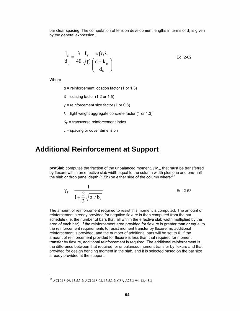
bar clear spacing. The computation of tension development lengths in terms of db is given ression: by the general exp
⎟⎟⎠
⎞⎜⎜⎝
⎛ +'b cf40d
αβγλ=
b
trc
yd
dk
f3l Eq. 2-62
α = reinforcement location factor (1 or 1.3)
β = coating factor (1.2 or 1.5)
λ = light weight aggregate concrete factor (1 or 1.3)
inforcement index
c = spacing or cover dimension
Additional Reinforcement at Support
pcaSlab computes the fraction of the unbalanced moment, γfMu, that must be transferred by flexure within an effective slab width equal to the column width plus one and one-half the slab or drop panel depth (1.5h) on either side of the column where:53
Where
γ = reinforcement size factor (1 or 0.8)
Ktr = transverse re
21
f
b/b21+3
1=γ Eq. 2-63
of
nt area provided for flexure is greater than or equal to e reinforcement requirements to resist moment transfer by flexure, no additional
at the slab, and it is selected based on the bar size
already provided at the support.
The amount of reinforcement required to resist this moment is computed. The amount reinforcement already provided for negative flexure is then computed from the bar schedule (i.e. the number of bars that fall within the effective slab width multiplied by the area of each bar). If the reinforcemethreinforcement is provided, and the number of additional bars will be set to 0. If the amount of reinforcement provided for flexure is less than that required for moment transfer by flexure, additional reinforcement is required. The additional reinforcement is the difference between that required for unbalanced moment transfer by flexure and thprovided for design bending moment in
ACI 318-99, 13.5.3.2; ACI 318-02, 13.5.3.2; CSA-A23.3-94, 13.4.5.3 53
94

It should be noted that the Code requires either concentration of reinforcement over er spacing, or additional reinforcement, to resist the transfer e slab width. pcaSlab provides additional reinforcement, and
does not concentrate existing reinforcement.
For the ACI Code, at least two of the column strip bottom bars should be continuous or spliced at the support with Class A splices or anchored with the support.
Integrity Reinforcement
For CSA A23.3-94 Code, the program performs calculation of the amount of integrity reinforcement at slab column connections. The integrity reinforcement is required for slabs without beams. The sum of all bottom reinforcement connecting the slab to the column on all faces of the periphery should meet the condition:
column beam joint by closmoment within the effectiv
y
sesb f
V2A ≥∑ Eq. 2-64
Corner Reinforcement
For CSA A23.3-94 Code, the program performs calculation of the amount of corner reinforcement in slabs with stiff edge beams (α greater than 1.0). This reinforcement is required within a region equal to 1/5 of the shorter span. The amount of corner reinforcement is calculated from the moment per unit width intensity corresponding to the maximum positive moment in span. The Code requires the corner reinforcement to be placed at top and bottom of the slab in bands parallel to the sides of the slab edges.
Deflection Calculation
Calculation of deflections of reinforced concrete two-way slabs is complicated by a large number of significant parameters such as: the aspect ratio of the panels, the vertical and torsional deflection of supporting beams, the stiffening effect of drop panels and column capitals, cracking, and the time-dependent nature of the material response. Based on studies (Ref. [22–24]), an approximate method consistent with the equivalent frame method was developed (Ref. [25]) to estimate the column and middle strip deflections.
95

Calculation of the midspan deflection of the column strip or the middle strip is based on I ratio of the strip to that of the full-width panel: the M/E
stripc
framec
frame
stripref,fstrip,f IE
IEMM
aa = Eq. 2-65
where af,ref is taken from the equivalent frame analysis assuming gross section (un-cracked) or effective (cracked) section properties.
The ratio (Mstrip/Mframe) can be considered as a lateral distribution factor, LDF. The lateral distribution factor, LDF, at an exterior negative moment region is:
⎟⎟⎠
⎞⎜⎜⎝
⎛−⎟⎟
⎠
⎞⎜⎜⎝
⎛αβ+β−=
1
2
1
21ttext,neg l
llll1210100LDF Eq. 2-66
negative moment region is: The LDF at an interior
⎟⎟⎠
⎞⎜⎜⎝
⎛−⎟⎟
⎠
⎞⎜⎜⎝
⎛α−=
11
The LDF at a positive moment region is:
221,intneg l
llll 3075LDF Eq. 2-67
⎟⎠
⎜⎝
−⎟⎠
⎜⎝α+=
ll5.1
ll 3060LDF
1
2
1
21pos Eq. 2-6
where
⎞⎛⎞⎛8
α1 = the ratio of flexure stiffness of a beam section to the flexural stiffness of a width of slab bounded laterally by centerlines of adjacent panels on either side of
hen αll2/l1 is greater than 1.0, αll2/l1 will be set equal to 1.0.
he column and middle strip LDF’s can be computed by:
the beam.
βt = ratio of torsional stiffness of an edge beam section to the flexural stiffness of a width of slab equal to the span length of the beam, center-to-center of the supports (see Eq. 2-28).
W
T
96

22
LDFLDF
pos
LDFLDF r.negl,neg
c
++
Eq. 2-70
LDFneg,r = LDF for the negative moment region at the right end of the span
= Eq. 2-69
cm LDF100LDF −=
where
LDFneg,l = LDF for the negative moment region at the left end of the span
The deflections should be used in conjunction with the deflections obtained from an analysis in the transverse direction. For square panels (l1 = l2), the midpanel deflection isobtained by Eq. 2-71 as shown in Figure 2-22:
mycxmxcy aaaaa +=+= Eq. 2-71
ined by Eq. 2-72: For rectangular panels, (l1 ≠ l2), the mid panel deflection is obta
( ) ( )2
aaaaa cxmymxcy +++= Eq. 2-72
dead load and live load combined
racking
If gross section properties option is selected for deflection calculations in the input, the deflection calculations will be based on the gross section Ig. If cracked section properties option is selected the effect of cracking on the deflection calculations is considered. The effect of cracking in slabs, as in beams, is a reduction in the flexural stiffness. The effect of cracking is generally an increase in deflections, although the tensile concrete between cracks continues to have a stiffening influence. A detailed review of several methods of deflection analyses can be found in Ref. [24].
When calculating the deflections for effective (cracked) section properties, the equivalent frame solution is obtained for two load levels:
dead load only
the effective section properties are assumed corresponding to the load level.
C
97

acx
acxamx
acy
acyamy
acx
acx
acy
acy
X
Y
X
Y
Y
x
x
y
y
X
Directionof Analysis
Directionof Analysis
a = acx + amy = acy + amx
Figure 2-22 Deflection computation for a square panel
To apply the Code-specified effective moment of inertia to slab systems, a value of Ia,frame is used instead. The value of Ia,frame is given by:
( )( )2
II1II r,el,e
eframe,a
−−+ +β−+β= Eq. 2-73
98

Where
e effective moment of inertia for the positive moment region.
Ie-,l = effective moment of inertia for the negative moment region at the left
support
Ie-,r = effective moment of inertia for the negative moment region at the right
support
β = an empirical constant based on experimental data, whose value is less than 1.0
For flat plates, flat slabs, and waffle slabs, the appropriate value of β appears to be 0.5. pcaSlab uses a value of 0.5 for flat plates, flat slabs, and waffle slab systems and 0.7 for beam-supported slabs.
The value of Ia,frame for cantilever spans is given by:
I + =
( ) −−β= II β−+ end.e,supeframe,a I1 Eq. 2-74
Where
Ie-,sup = effective moment of inertia for the negative moment region at support.
For flat plates, flat slabs, and waffle slabs, the appropriate value of β appears to be 1.0. pcaSlab uses a value of 1.0 for flat plates, flat slabs, waffle slabs, and beam-supported
The value of I corresponds to the effective moment of inertia as developed by Branson
Ie-,end = effective moment of inertia for the negative moment region at the
cantilever end
slabs.
e(Ref. [26]) and incorporated into the Code as follows:54
cr
3
max
crg
3
max
cre I
MM1I
MMI
⎥⎥⎦
⎤
⎢⎢⎣
⎡⎟⎟⎠
⎞⎜⎜⎝
⎛−+⎟⎟
⎠
⎞⎜⎜⎝
⎛= Eq. 2-75
Where
Ig = moment of inertia of the gross uncracked concrete section for the full width of the equivalent frame.
54 ACI 318-99, 9.5.2.3; ACI 318-02, 9.5.2.3
99

I = moment of inertia of the cracked transformed concrete section for the full quivalent frame.
Mcr = cracking moment for the full width of the equivalent frame.
Mmax = maximum bending moment for the full width of the equivalent frame at the load stage at which the deflection is computed.
It should be noted that the use of the full slab width in determining Ie in Eq. 2-75 is intended to average the effects of cracking of the column and middle strips.
Deflection Computations
Instantaneous Deflections: Two values of mid-span deflections are computed by the program for each span. The first corresponds to dead load on all spans, while the second corresponds to dead load plus live load on all spans. Note that the live load deflection is always computed as total load deflection minus the dead load defection. This is consistent with the Ieff method outlined in the Code.
Long term deflection calculations are beyond the scope of the program. Users need to calculate long term deflection manually. The total mid-panel
eflection (including long-time effects) consists of the following:
crwidth of the e
Long Time Deflections:
d
shcreepetotal aaaa ++= Eq. 2-76
Where
ae = elastic deflection
acreep = additional deflection due to creap.
ash = additional deflection due to shrinkage
atotal = total deflection.
Data reported in the literature, although limited in quantity, indicate that the additional deflection due to creep and shrinkage, acreep + ash, may be as much as two to eight times the elastic deflection, ae (Ref. [27-30]). Such a factor times the dead load deflection may be used for an estimate of required slab camber.
For a crude approximation to a complex problem, additional long-time deflections may be computed as three times the elastic deflections. For a more detailed method of analysis of long-time deflection the user is referred to a study by Rangan (Ref. [30]).
100

Material Quantities
computes concrete and reinforcing steel quantities. The quantity of concrete based on an average of the slab, drop, and beam sizes. The total quantity of
reinforcing steel computed by the program corresponds to the actual bar sizes and wance is made for bar hooks, anchorage embedment,
ty of reinforcement printed by the program ertains to bending in one direction only. In practice, the total amount of reinforcement for
The programis
lengths required by design. No alloand so forth. It should be noted that the quantipthe structure should also include the quantities obtained for the appropriate transverse equivalent frames.
101

Ch. User Interface Components Chec
3 User Interface Description
k Boxes
Figure 3-1 Check Boxes
A check box is a toggle used in a dialog box that enables or disables an option. To
s the space bar to activate the option.
Checked Menu Commands
enable a check box, toggle the switch so that a sign is placed in the box. Removing the sign from the check box disables the command. Click once in the check box with the
mouse to enable or disable the command or use the keyboard keys to tab to the check box and pres
102

Figure 3-2 Checked Menu Commands
If the menu commands are checked with a sign on the left, the menu commands are enabled in the current project. To disable the command, single click the left mouse button
ommand to clear the sign. For example, since the Toolbar and Status bar the image above, both the toolbar and status bar will appear in
e main window of pcaSlab.
Command Buttons
on the ccommands are checked in th
Figure 3-3 Command Buttons
Command buttons such as Ok and Cancel buttons that are located inside dialog boxes, are labeled to do exactly what they say. After you have completed your input within a dialog box, click once with the left mouse button on Ok (all Windows) or press Alt + O with the keyboard keys (Windows 95, 98, ME) to save the changes. If, while working in a dialog box, you want to disregard the data you have input, select Cancel (all Windows) to exit and discard any new data. When using the keyboard keys select Alt + C (Windows 95, 98, ME).
103
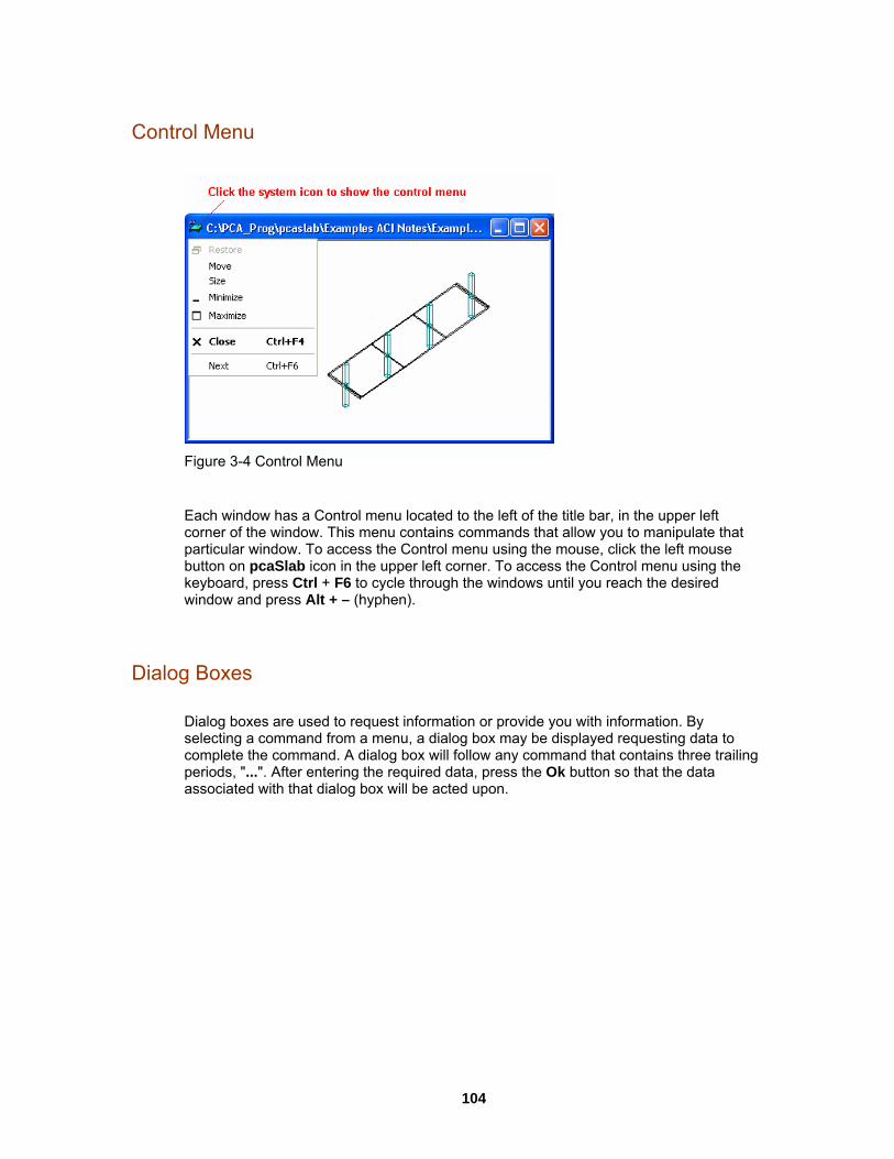
Control Menu
Figure 3-4 Control Menu
Each window has a Control menu located to the left of the title bar, in the upper left corner of the window. This menu contains commands that allow you to manipulate that particular window. To access the Control menu using the mouse, click the left mouse button on pcaSlab icon in the upper left corner. To access the Control menu using the keyboard, press Ctrl + F6 to cycle through the windows until you reach the desired window and press Alt + – (hyphen).
Dialog Boxes
ialog boxes are used to request information or provide you with information. By a command from a menu, a dialog box may be displayed requesting data to
Dselectingcomplete the command. A dialog box will follow any command that contains three trailing periods, "...". After entering the required data, press the Ok button so that the data associated with that dialog box will be acted upon.
104

Drop-down List
Figure 3-5 Drop-down List
A drop-down list is a list box that appears initially as a rectangular box with the current selection marked. To see a list of available choices, click the arrow to the right of the box or press Alt + DOWN ARROW to open the box. You can now select another item in a similar way as you would use a list box.
Usually there are some items in a drop-down list. You may click the left mouse button on the button on the right side of the list to extend the list. Then select the item you need
clicking the left mouse button on the item. The selected item will appear in the text box on the top of the drop-down list. If there are too many items in a drop-down list, a vertical scroll bar will appear automatically so that you can use it to scroll up and down.
by single
105

Drop-down Menu
Figure 3-6 Drop-down Menu
A drop-down menu is the menu that is shown directly beneath the menu line when you click one of the menu items on the menu line using the left mouse button.
Fthe "File" on the menu lin
or example, the File menu appears directly beneath the "File" menu item when you click e or press Alt + F using keyboard.
Enable/Disable Options
Figure 3-7 Enable/Disable Options
106

Some commands in the pop-up menus or input controls in the dialog boxes are black
ers are gray. Commands that are black are available for use at that time. s that are grey are not available but may become available depending on the
a you enter. For example, in the Input menu, the Reinforcing Bars command is gray at the start of a new file. When you change the Run Mode from Design to Investigation in the General Information dialog box you will notice that the Reinforcing Bar command becomes black and is now ready for your input.
Frame Boxes
while othCommanddat
Figure 3-8 Frame Boxes
A frame box groups some related objects together, such as text boxes or option buttons.
107

List Boxes
Figure 3-9 List Boxes
A list box displays a list of choices or items. If there are more choices than can fit in the ox, scroll bars are provided so you can move quickly through the list.
croll bar) or at the bottom (horizontal scroll bar) of a list box. It has two directional arrows at either end (up and
own, or left and right) in addition to a small rectangle called the scroll box. The location f the scroll box with respect to the length of the bar indicates the proportion of the
amount of the information in view to the whole list.
To scroll through information displayed in a list box one line at a time, click the up or down scroll arrow or, using the keyboard, press the arrow key that points in the direction you want to scroll. Another way is to click inside the scroll bar above or below the scroll box. This scrolls the list one screen at a time (the keyboard equivalent is pressing the Page Up or Page Down key). If you drag the scroll box in the scroll bar, the section of the list that moves into view depends on where you position the scroll box.
To select a single item from a list box:
Click the scroll arrows until the item you want to select appears in the list box. Click the item.
b
The scroll bar is usually located to the right (vertical s
do
108

e directional arrow keys to scroll to the item you want.
o select multiple sequential items in a list:
Click the first item you want to select and then drag the cursor to the last item you want to select. Alternatively, click on the first item you want to select, press and hold down the Shift key, and click on the last item you want to select. Both items, and all items in between, are selected. To cancel the selections, release the Shift key and click any item.
Using the keyboard, use the UP ARROW or DOWN ARROW key to move the cursor to the first item you want to select. Press and hold down the Shift key. Continue to press the arrow key repeatedly until all the items you want are selected. To cancel the selections, release the Shift key and press one of the arrow keys.
To select multiple non-sequential items in a list:
Press and hold down the Ctrl key, and click each item you want to select. To cancel a selection, press and hold down the Ctrl key, and click the item again. There are no
ocedure.
om a list box to the clipboard:
rthermore, the copied information can sferred to other Windows applications (such as Microsoft Excel) using the
pplication's Edit/Paste command. The transferred information will be indented and tabulated.
Using the keyboard, use th
T
keyboard equivalents for this pr
Copying fr
Selected items in a list box can be copied to the clipboard by simply pressing F3 after youmake your selection. You will be able to view the contents of the clipboard by opening the Clipboard Viewer in the Program Manager. Fube trana
109

Option Buttons
Figure 3-10 Option Buttons
ptions from which you may select only one. A is le,
, itch ing
An option button is used in a group of ogroup of option buttons is a type of toggle (on/off) switch that when one option button chosen, its state is toggled on and all other option buttons are toggled off. For exampin the General Information dialog box you will see option buttons. When using a mouseplace the cursor over the option desired and click the left button once to toggle the swon. When using the keyboard keys, tab to the group of options and choose one by usthe up and down arrow keys to toggle the switch.
110

Pop-up Menu
Figure 3-11 Pop-up Menu
right mouse button on a view window. The commands on a pop-up menu are usually the commonly used ommands associated with the view window that you right click on.
A pop-up menu is the menu that is shown when you click the
c
111

Tabs
Figure 3-12 Tabs
integrated together in a more compact interface. Each tab is actually a dialog box itself and each tab has a tab title. For example, there are three tabs in the image shown above and the titles for them are Slabs, Longitudinal
ibs, respectively. You may see different text boxes, option buttons, etc. on bs. To push a tab to the top or to activate a tab, single click the left mouse
title of the tab that you want to access. Once a tab is activated (on the top), er tabs are covered by the activated one and cannot be accessed.
Tabs are different dialog boxes that are
Beams, and Rdifferent tabutton on the oth
112
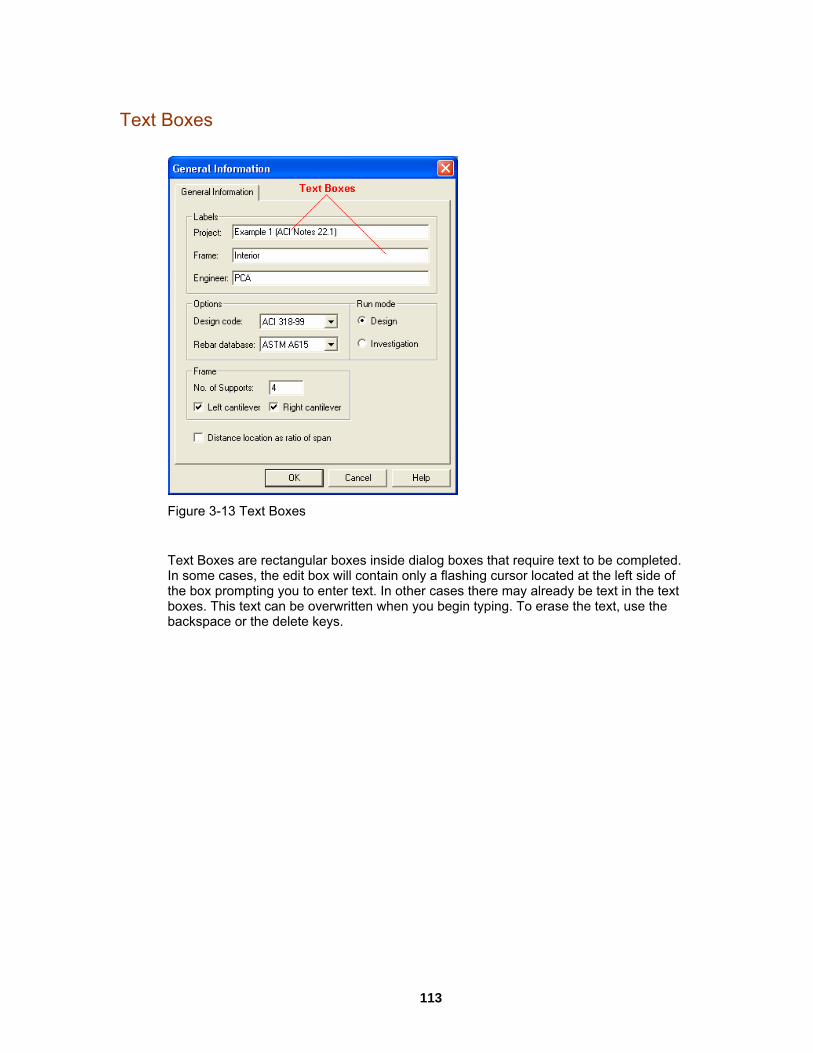
Text Boxes
Figure 3-13 Text Boxes
Text Boxes are rectangular boxes inside dialog boxes that require text to be completed. some cases, the edit box will contain only a flashing cursor located at the left side of e box prompting you to enter text. In other cases there may already be text in the text
Inthboxes. This text can be overwritten when you begin typing. To erase the text, use the backspace or the delete keys.
113
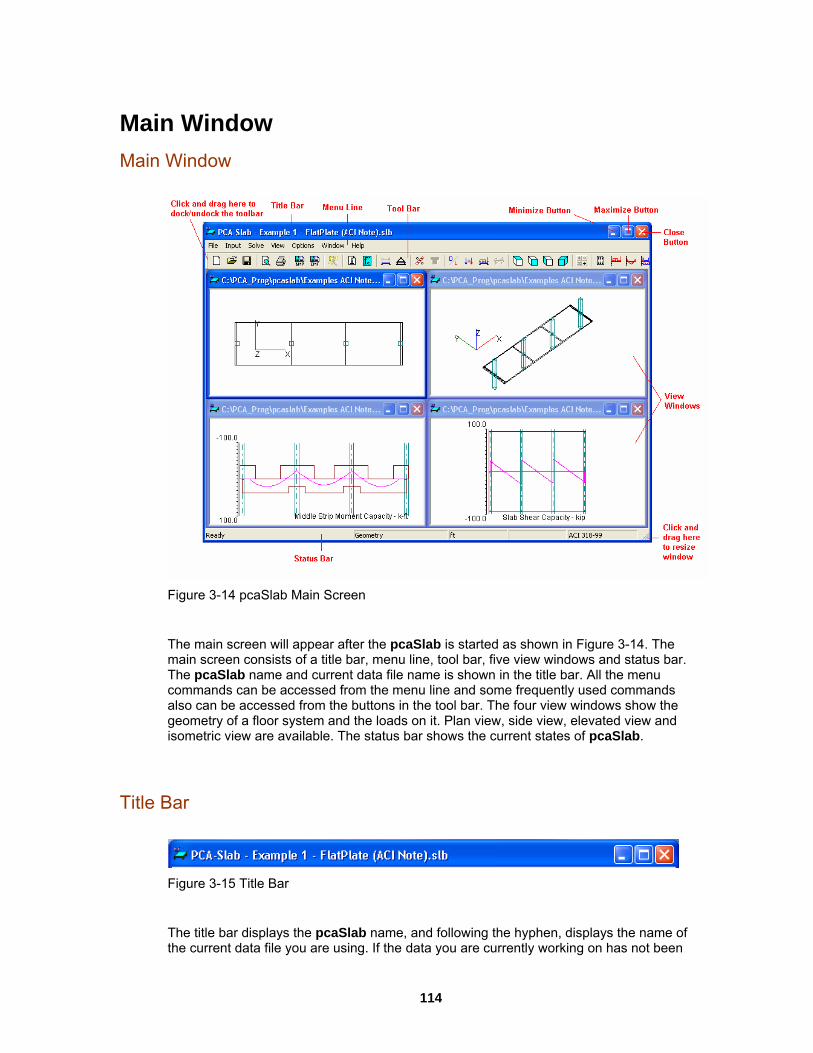
Main Window Main Window
Figure 3-14 pcaSlab Main Screen
The main screen will appear after the pcaSlab is started as shown in Figure 3-14. The main screen consists of a title bar, menu line, tool bar, five view windows and status bar. The pcaSlab name and current data file name is shown in the title bar. All the menu ommands can be accessed from the menu line and some frequently used commands
also can be accessed from the buttons in the tool bar. The four view windows show the of a floor system and the loads on it. Plan view, side view, elevated view and
w are available. The status bar shows the current states of pcaSlab.
Title B
c
geometryisometric vie
ar
Figure 3-15 Title Bar
The title bar displays the pcaSlab name, and following the hyphen, displays the name ofthe current data file you are using. If the data you are currently working on ha
s not been
114

saved into a file, the word pcaSlab1 is displayed in the title bar. If you start an other new data file by clicking the New button on the most left of the tool bar, the next data file is
caSlab2, and so on.
Menu
named as p
Line
Figure 3-16 Menu line
Located directly below the title bar is the menu line. pcaSlab commands are listed in the
ted in the menu line. These menu commands allow you to perform , view, and ultimately design the floor system.
the pcaSlab program there are seven main pop-up menus: File, Input, Solve, View, , Windows, and Help. To access a menu item using the mouse, place the arrow
menu item you want and click the left mouse button. Each menu item can ed with the keyboard keys by simultaneously pressing the Alt key and the
, to open the File menu, e the cursor to any
lank area on the screen and click the left mouse button. Press Esc key to close a menu using the keyboard keys.
the item you double click on a
election, that is, press the mouse button twice, quickly. Anytime you have to wait, for en loading the program or designing the system, the mouse cursor becomes
n hourglass cursor. It will return to its original state when the task is completed.
menu using the keyboard, use the down arrow key to
Tool Bar
pop-up menus locafunctions that create InOptionscursor on the also be selectunderlined letter of the menu you want to open. For examplepress Alt + F. To close a menu without selecting a command, movb
To select a command from a menu with the mouse, place the arrow onwant, and click the left mouse button. In some cases, you will be told tosexample, wha To select a command from ahighlight your choice and press Enter key or press the keyboard key of the command’s underlined letter. The space bar is also equivalent to pressing the left mouse button. Special instructions for inputting with the keyboard keys are given wherever necessary.
Figure
irectly below the menu lin ool bar. Some frequently used buttons can be found in the tool bar. A description of the corresponding button is shown in the status bar
n the bottom of the window) when the mouse cursor is moving over this button. In addition to the description in the status bar, a brief tip is shown in a light yellow colored pop-up window close to the corresponding button when a mouse cursor is hanging over
3-17 Tool Bar
Located d e is the t
(o
115

the button for a short period of time. Exactly the same functions or features can be accessed from either the menu items or tool bar buttons. The tool bar can be changed from docking status to floating status by single clicking the left mouse button on the tool bar and dragging it away from the docking position to any other positions on the screen. A floating tool bar can be resized by clicking and dragging its borders. To restore the tool bar to the docking status, single click the left mouse button on the tool bar and drag it to the location that is directly below the menu line and release the mouse button.
View Windows
Figure 3-18 View Windows
ment.
A total of 10 view windows can be used to show Plan, Elevated, Side and Isometric viewsof the geometry, as well as Loads, Shear and Moment, Moment Capacity, Shear Capacity, Deflection, and Reinforce
116
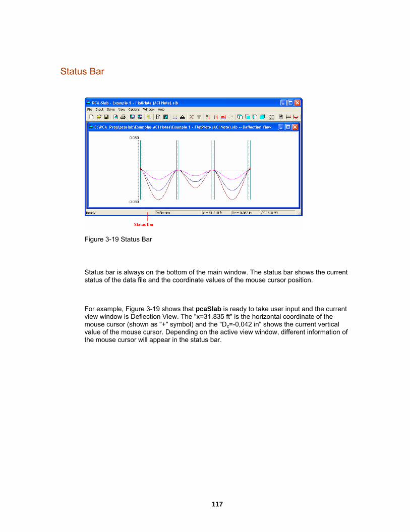
Status Bar
Figure 3-19 Status Bar
Status bar is always on the bottom of the main window. The status bar shows the current status of the data file and the coordinate values of the mouse cursor position.
For example, Figure 3- shows that pcaSlab is ready to take user input and the current View. The "x=31.835 ft" is the horizontal coordinate of the +" symbol) and the "Dz=-0,042 in" shows the current vertical
rsor. Depending on the active view window, different information of
19view window is Deflection mouse cursor (shown as "value of the mouse cuthe mouse cursor will appear in the status bar.
117

MainFile M
Menu enu
Figure 3-20 File Menu
The File menu is used for saving or retrieving data, printing, and exiting. The File menu
mmands: New, Open, Close, Save, Save As, Print Preview, Print Results, Print Setup, Recent Files and Exit.
he New command clears any data input and returns to the default values. Thus, you are ble to create a new data file. However, before you can begin a new data file, pcaSlab
will ask whether you want to save the current data as shown in Figure 3-21. Answering Yes will save the old data and begin a new data file. Answering No will discard any
ring Cancel will return you to pcaSlab so that you can continue to work with the current data.
contains the following co
New Ta
changes to the data and begin a new data file. Answe
Figure 3-21 Save Change Dialog Box
Open The Open command allows you to load an existing pcaSlab data file. The dialog box that appears shows you a listing of all the files with the extension contained in the default data directory or in the current directory (if a default data directory was not specified). This box also enables you to change the current drive and directory. If you are currently working
118

on a data file and select the Open command, pcaSlab will ask whether you want to save the current data. Answering Yes will save the old data and display the Open dialog box.
will discard any changes to the data and display the Open dialog box. ncel will return you to pcaSlab so that you can continue to work with the
rent data.
Close The Close command allows you to close the current pcaSlab data file. If you are currently working on a data file and select the Open command, pcaSlab will ask whether you want to save the current data. Answering Yes will save the old data and display the Open dialog box. Answering No will discard any changes to the data and display the Open dialog box. Answering Cancel will return you to pcaSlab so that you can continue to work with the current data.
Save The Save command saves the changes you’ve made to the current data under that same filename. The new data overwrites the old data, and you cannot retrieve the old data. It ia good practice to periodically save while inputting data. If a data file is untitled, the Save
shown in Figure 3-22.
Answering NoAnswering Cacur
s
As dialog box will appear as
Figure 3-22 Save As Dialog Box
n
name exists, will ask if you would like to overwrite the file.
The Print Preview command allows you to preview and print the current view window (floor system geometry in the plan, elevated, and isometric views, prints the shear and
Save As The Save As command allows you to name or rename a data file. Use Save As wheyou want to save both the original data and any changes you’ve currently made to the data. The original data remains under the old filename. If a file of the same the program
Print Preview
119

moment diagrams, and prints the deflected shapes). To obtain a view window you mufirst perform the design, then select what you want to view from the View menu. You mhave more than one view
st ay
windows opened. The current view window is the one activated and on top of the others on your screen. Selecting this command closes the pcaSlab main window and opens the print preview window as shown in Figure 3-23. On the print preview window, press the Zoom In or Zoom Out buttons or simply click the left mouse
the preview window to magnify or reduce the size of the preview paper. Press Page button if more than one page needs to be printed. Press the Print button
rint the view. The printer could be a local printer, which is connected to your computer d rk printer. Press the Close button to close the preview window and go back to pcaSlab.
button onthe Nextto p
irectly, or a netwo
Figure 3-23 Print Preview Window
n in Figure 3-24. By selecting options in the Output Options dialog box prior to performing the print, you can print selected sections of the data instead of the entire analysis.
Print Results The Print Results command allows you to send the analysis and/or design results to the printer. Selecting this command will show the Result Options dialog box as show
120

Figure 3-24 Result Options Dialog Box
Recent Files his list contains the data files that are used recently and can be accessed quickly from e menu by a single click. The most recently used one is on the top of the list. Up to four
listed.
ade any changes to your data and have not saved them, pcaSlab will first ask whether you want to save or abandon any changes you’ve made before you exit.
Input
Tthfiles can be
Exit The Exit command ends the pcaSlab session and returns you to Windows. If you’ve m
Menu
Figure 3-25 Input Menu
121
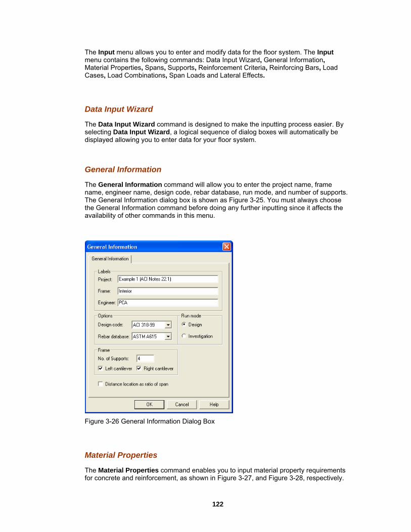
The Input menu allows you to enter and modify data for the floor system. The Input menu contains the following commands: Data Input Wizard, General Information,
Properties, Spans, Supports, Reinforcement Criteria, Reinforcing Bars, Load Cases, Load Combinations, Span Loads and Lateral Effects.
ata Input Wizard
ta Input Wizard command is designed to make the inputting process easier. By will automatically be
The General Information command will allow you to enter the project name, frame e, engineer name, design code, rebar database, run mode, and number of supports.
neral Information dialog box is shown as Figure 3-25. You must always choose e General Information command before doing any further inputting since it affects the
availability of other commands in this menu.
Material
D
The Daselecting Data Input Wizard, a logical sequence of dialog boxesdisplayed allowing you to enter data for your floor system.
General Information
namThe Geth
Figure 3-26 General Information Dialog Box
aterial Properties
The Material Properties command enables you to input material property requirements for concrete and reinforcement, as shown in Figure 3-27, and Figure 3-28, respectively.
M
122

C ell as oncrete density, compressive strength, Young’s modulus, rapture modulus, as wthe longitudinal and shear reinforcement yield levels, are required.
Figure 3-27 Concrete Properties Dialog Box
Figure 3-28 Reinfo
rcing Steel Properties Dialog Box
123

Sp
T
ans
he Spans menu allows you to input geometric dimensions for slabs, longitudinal beams, and ribs, as shown in Figure 3-29.
F
p
The Supports menu allows you to input geometric dimensions for columns, drop panels, column capitals, and transverse beams, as shown in Figure 3-30. The percentage of the actual column joint stiffness to be used in the analysis to determine the joint moments
umns tab.
igure 3-29 Spans Dialog Box
Su ports
and shears can be modified on the Col
124

Figure 3-30 Supports Dialog Box
Reinforcement Criteria
The Reinforcement Criteria menu allows you to specify the distance to reinforcement, reinforcement bar sizes, bar spacing, and reinforcing ratio for both slabs and beams.
125
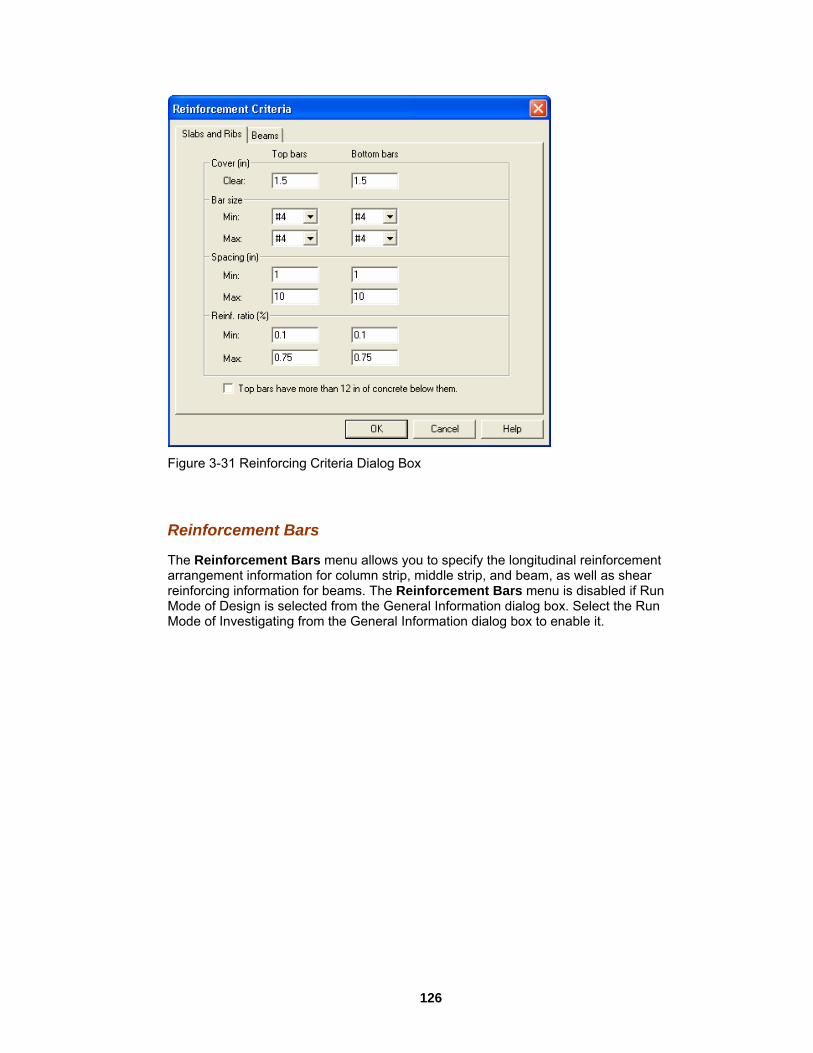
Figure 3-31 Reinforcing Criteria Dialog Box
Reinforcement Bars menu allows you to specify the longitudinal reinforcement rrangement information for column strip, middle strip, and beam, as well as shear
reinforcing information for beams. The Reinforcement Bars menu is disabled if Run Mode of Design is selected from the General Information dialog box. Select the Run Mode of Investigating from the General Information dialog box to enable it.
Reinforcement Bars
The a
126
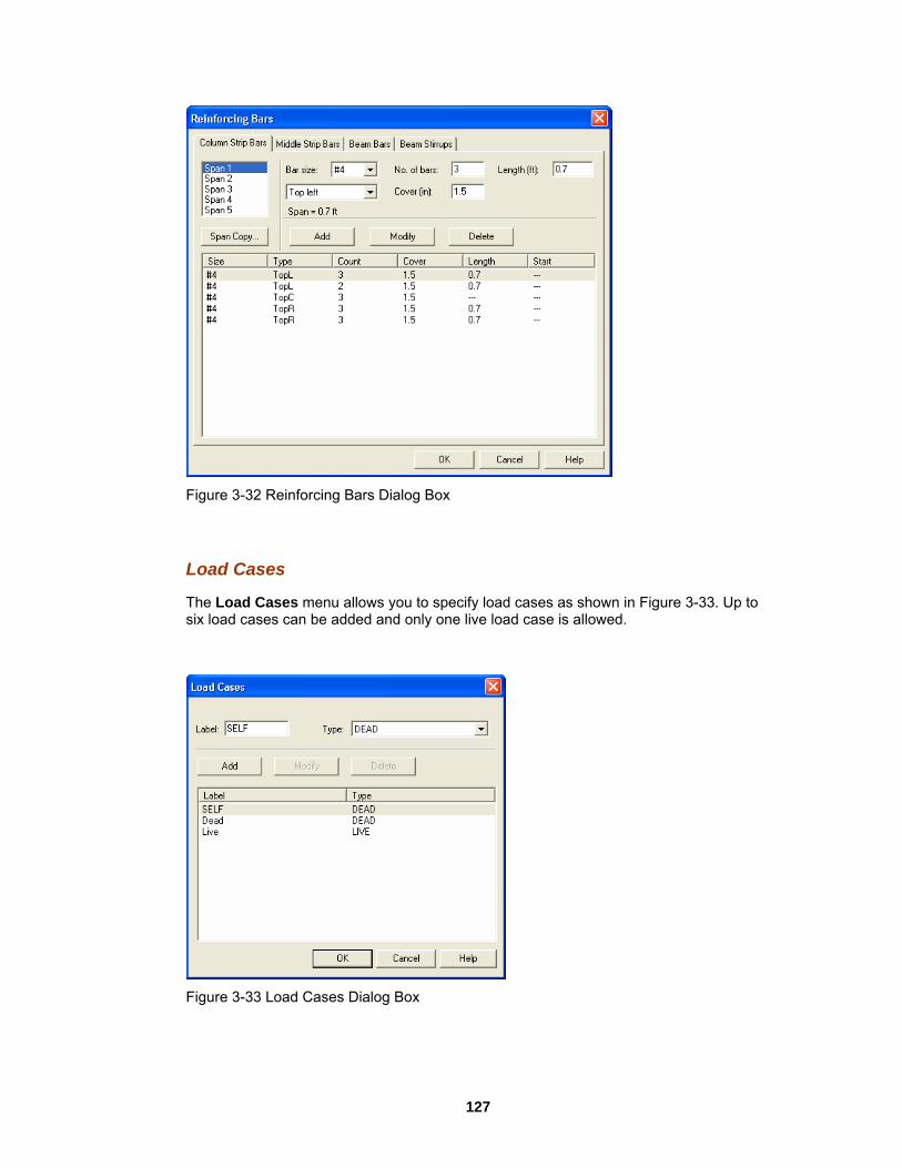
Figure 3-32 Reinforcing Bars Dialog Box
Load Cases
The Load Cases menu allows you to specify load cases as shown in Figure 3-33. Up to six load cases can be added and only one live load case wed. is allo
Figure 3-33 Load Cases Dialog Box
127

Load Combinations
The Load Combinations menu allows you to specify load combinations as shown in Figure 3-34. Up to twelve load combinations can be added.
Figure 3-34 Load Combinations Dialog Box
ows you to enter superimposed area loads, line loads, point loads, and moments.
Span Loads
The Span Loads menu all
128

Figure 3-35 Span Loads Dialog Box
Lateral Effects
The Lateral Effects menu allows you to enter the lateral loads as moments acting on the two ends of each span.
Figure 3-36 Lateral Effects Dialog Box
129

Solve Menu
Figure 3-37 Solve Menu
The Solve menu contains commands that enable you to perform the analysis and/or
iew the results. The Solve menu contains the following ecute, and Report.
Solve
The sec3-38. Tocomma
design of the floor system and vcommands: Solve Options, Ex
Options
lve Options command allows you to specifSo y the live load pattern ratio, critical tion of punching shear, and the section to calculate deflection, as shown in Figure
take effect, the design must be performed after the Condense/Expand Output nd is executed.
8 Solve Options Dialog Box Figure 3-3
Execute
Therequi derror me
Execute command executes the solver portion of pcaSlab. If some data is still re when this command is executed, pcaSlab will respond with an "Invalid Model!"
ssage, as shown in Figure 3-39.
130
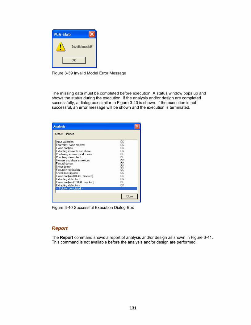
Figure 3-39 Invalid Model Error Message
The missing data must be completed before execution. A status window pops up and show etesucsuccess
s the status during the execution. If the analysis and/or design are compl d cessfully, a dialog box similar to Figure 3-40 is shown. If the execution is not
ful, an error message will be shown and the execution is terminated.
Figure 3-4
he Report command shows a report of analysis and/or design as shown in Figure 3-41. sign are performed.
0 Successful Execution Dialog Box
Report
TThis command is not available before the analysis and/or de
131

Figure 3-41 View Results Window
View Menu
Figure 3-42 View Menu
The View menu commands enable you to modify the floor system’s appearance on the screen to suit your viewing needs and enable you to view the result diagrams. The View menu contains the following commands: Zoom, Pan, Restore, Plan View, Elevated View, Side View, Isometric View, Change View Angles, View Options, Loads, Shear
132

and Moment, Moment Capacity, Shear Capacity, Reinforcement, Deflection and Duplicate Active View.
s a cascade sub-menu, which enables you to zoom in and out f your floor system. Select Window from the sub-menu and use the
mouse to specify a zooming region; the program will enlarge the portion you select. elect the In(2x) or Out(0.5x) to enlarge or reduce the model by two times, respectively.
The Pan command allows you to move your model on the plane of the screen. You may move the model in any direction. The mouse curser is changed to a palm shape once the Pan command is selected. Press and hold the left mouse button on the view window and
on. After the mouse button is released, the model is moved in the rection as the mouse curser from the original position.
lan View
Sele
Elevated View
Select Elevated View d view window.
Sid
Select Side View command to show the side view window.
Isome
Select I isometric view window.
Zoom
The Zoom menu containon any portion o
S
Pan
drag to the new locatisame distance and di
Restore
The Restore command will redraw the floor system in full size. If you have altered your screen view using the Zoom command, select Restore to restore the figure’s original proportions.
P
ct Plan View command to show the plan view window.
command to show the elevate
e View
tric View
sometric View command to show the
133
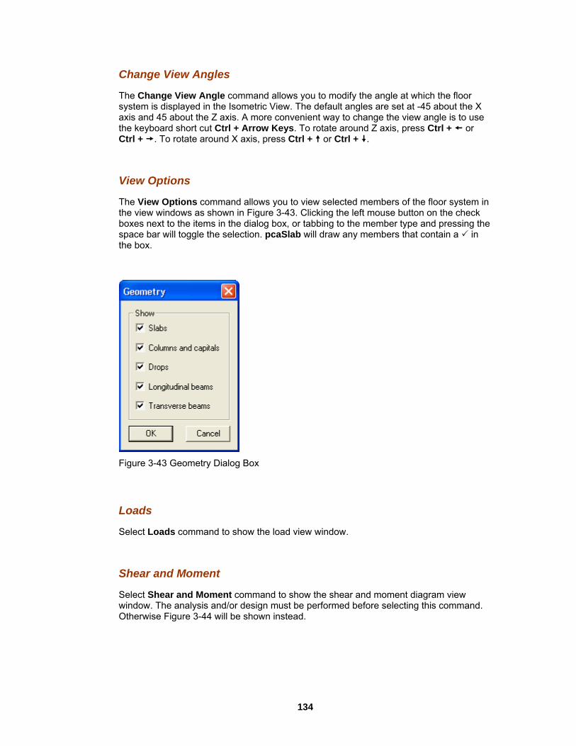
Ch
The Change View Angle command allows you to modify the angle at which the floor system is displayed in the Isometric View. The default angles are set at -45 about the X axis and 45 about the Z axis. A more convenient way to change the view angle is to use
ut Ctrl + Arrow Keys. To rotate around Z axis, press Ctrl + or round X axis, press Ctrl + or Ctrl + .
n
ange View Angles
the keyboard short cCtrl + . To rotate a
View Options
The View Options command allows you to view selected members of the floor system ithe view windows as shown in Figure 3-43. Clicking the left mouse button on the check boxes next to the items in the dialog box, or tabbing to the member type and pressing the space bar will toggle the selection. pcaSlab will draw any members that contain a in the box.
-43 Geometry Dialog Box Figure 3
Loads
Select L
Shear
Sel ment diagram view indow. The analysis and/or design must be performed before selecting this command.
gure 3-44 will be shown instead.
oads command to show the load view window.
and Moment
ect Shear and Moment command to show the shear and mowOtherwise Fi
134

Figure 3-44 Problem Not Solved Window
indow. wise
elect Shear Capacity command to show the shear capacity diagram view window. The anaFigu
Reinforcement
Select R forcement view window. The analysis esign must be performed before selecting this command. Otherwise Figure 3-44
ill be shown instead.
De
Select Dand/or d will be s
Dup c
Select D
Moment Capacity
Select Moment Capacity command to show the moment capacity diagram view wThe analysis and/or design must be performed before selecting this command. OtherFigure 3-44 will be shown instead.
Shear Capacity
Slysis and/or design must be performed before selecting this command. Otherwise re 3-44 will be shown instead.
einforcement command to show the reinand/or dw
flection
eflection command to show the deflection diagram view window. The analysis esign must be performed before selecting this command. Otherwise Figure 3-44hown instead.
li ate Active View
uplicate Active View to make a copy of the current avtive view window.
135

Options Me
nu
u
The Options menu allows you to change the startup options of the pcaSlab program to suit your needs. The Options menu contains the following commands: Colors, Startup Defaults, Rebar Database, Toolbar, and Status Bar.
Colors
The Colors command allows you to change the background color, member color, load color, text color, diagram color, etc., as shown in Figure 3-46. You may save the new colors as default setting, which will be used when pcaSlab is executed in the future.
Figure 3-45 Option men
Figure 3-46 Changing Color Dialog Box
136

Startup Defaults
The Startup Defaults command allows you to enter engineer name, change the default design code, rebar database, and the data directory, a directory where pcaSlab looks for data when it is executed.
Figure 3-47 Startup Default Dialog Box
ebar Database
The b ed rebar information and defi ned database can be elected from the General Information dialog box.
R
Re ar Database command allows you to view the pre-definne your own database as shown in Figure 3-48. The user-defi
s
137
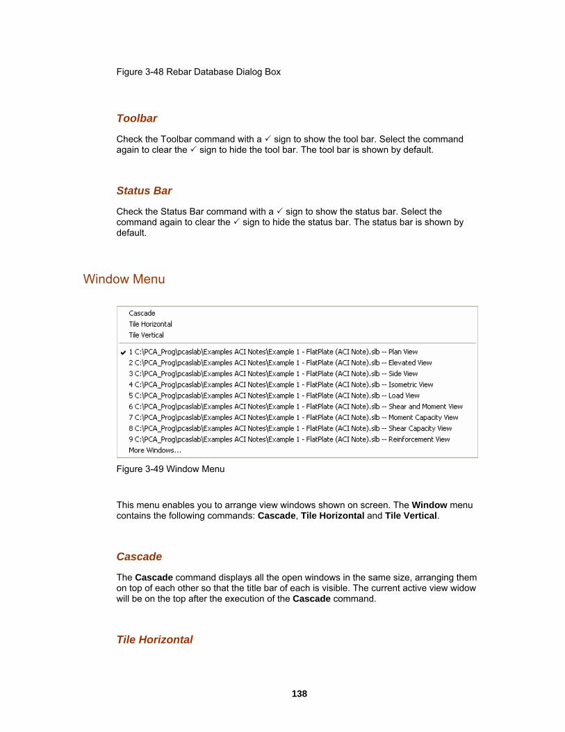
Figure 3-48 Rebar Database Dialog Box
oolbar
Check t ow the tool bar. Select the command again to tool bar is shown by default.
Sta
ck the Status Bar command with a sign to show the status bar. Select the ommand again to clear the sign to hide the status bar. The status bar is shown by
default.
Window Menu
T
he Toolbar command with a sign to sh clear the sign to hide the tool bar. The
tus Bar
Chec
Figure -49 Window Menu 3
Thiscontains the following commands: Cascade, Tile Horizontal and Tile Vertical.
e
nd displays all the open windows in the same size, arranging them n top of each other so that the title bar of each is visible. The current active view widow
menu enables you to arrange view windows shown on screen. The Window menu
Cascad
The Cascade commaowill be on the top after the execution of the Cascade command.
Tile Horizontal
138

The overlap -
ft corner of the screen after the execution of the Tile Horizontal command.
Tile Vertical
The Tile Vertical command arranges all open windows vertically so that no window overlaps another. The current active view widow will be on the most left or on the upper-left corner of the screen after the execution of the Tile Vertical command.
Remaining Commands
The remaining menu items are in a list of the windows that are available for viewing. Selecting any window from this menu will restore the window to its previous size and position from an icon.
Help Menu
Tile Horizontal command arranges all open windows horizontally so that no windows another. The current active view widow will be on the most left or on the upper
le
3
The Hel r the
caSlab program and show the copyrights and registration information about your oftware. The Help menu contains the following commands: Index and About pcaSlab.
ontents
The The topindex ofdouble c m can be obtained
Index
The a tri-pane window. The left pane contains the tablpane by he topic on the left pane. More information on the help system can o
Figure -50 Help menu
p menu includes commands that enable you to obtain online help fops
C
Contents command shows the electrical version of this manual in a tri-pane window. pane contains the commonly used control buttons. The left pane contains the all the help topics. The contents of a topic can be shown in the right pane by licking the topic on the left pane. More information on the help syste from the Microsoft Windows manual.
Ind d shows the electrical version of this manual in top pane contains the commonly used control buttons. The
ex comman
e of contents of all the help topics. The contents of a topic can be shown in the right single clicking t
be btained from the Microsoft Windows manual.
139

Ab
The About pcaSlab command displays a dialog box that gives you copyright information, pcaSlab program, your firm name, city, and state.
The C
out pcaSlab
the version number of the
ontrol Menu
Figu
All the vthe ope F6 to cy enu of the desimenu.
Resto
The Re on. This me available when the window is iconized or maximized.
Move
The Move command moves the window to a new location. Select Move and use the arrow keys to move the window in the desired direction and select Enter to accept the new location.
Size
re 3-51 Control Menu
iew windows have one pull-down menu located in the upper left hand corner of n window. This is the Control menu. To access the Control menu, press Enter +cle through the windows and press Alt + – (hyphen), to open the Control mred window. The following is a list and a brief description of the commands in this
re
store command will restore a window or an icon to its previous size and positinu item is
140

The Size command resizes a window. Select Size and use the arrow keys to move the border of the window in the desired direction and select Enter to accept the new size.
Minimize
The Minimize command reduces a window to an icon and positions it at the bottom of the screen.
Maximize
The Maximize command enlarges a window to fit your entire screen.
Close
The Close command is used to close a window and return it to an icon and the bottom of the screen.
Next
The Next command switches among open windows and icons.
Program Toolbar Toolbar
Figure 3
-52 Program Toolbar
Cl se the current data file if there is one and start a new data file. The equivalent ommand is File/New. o
men
u c
Open an existing data file on hard disk. The equivalent menu command is ile/Open.
F
Save the current data file to hard disk. The equivalent menu command is File/Save. If you have not changed the default file name (pcaSlab1, pcaSlab2, etc.), the equivalent menu command is File/Save As.
141

Print view window. The equivalent menu command is File/Print View.
and is File/Print Results. Print results. The equivalent menu comm
Copy Bitmap to clipboard. The bitmap then can be pasted to a word processing or entation software such as Microsoft Word or Microsoft PowerPoint. pres
Copy Metafile to clipboard. The metafile then can be pasted to a word processing or presentation software such as Microsoft Word or Microsoft PowerPoint.
Open the Data Input Wizard. The Data Input Wizard will guide you to enter the necessary input to your project. The equivalent menu command is Input/Data Input Wizard.
Enter general information. The equivalent menu command is Input/General Information.
Enter material properties. The equivalent menu command is Input/Material Properties.
Enter span geometry information for slabs, longitudinal beams, and ribs. The equivalent menu command is Input/Spans.
Enter support information for columns, drop panels, column capitals, and transverse beams. The equivalent menu command is Input/Support.
En beams. The equivalent menu ter reinforcement criteria for slab and ribs, andmand is Input/Reinforcement Criteria. com
Enter reinforcing bar information for column strips, middle strips, beams, and beam s. This button is disabled if Design run mode is selected from the General
ma and is Input/Reinforcing Bars. stirrupInfor tion dialog box. The equivalent menu comm
Enter load cases. The equivalent menu command is Input/Load Cases.
Enter load combinations. The equivalent menu command is Input/Load mbinations. Co
Enter span loads. The equivalent menu command is Input/Span Loads.
142

Enter lateral effects. The equivalent menu command is Input/Lateral Effects.
ommand is View/Plan View. View plan geometry. The equivalent menu c
View elevated geometry. The equivalent menu command is View/Elevated View.
View side geometry. The equivalent menu command is View/Side View.
View isometric geometry. The equivalent menu command is View/Isometric View.
Execute the analysis and/or design. The equivalent menu command is e/Execute. Solv
View results. The equivalent menu command is Solve/Report.
View loads. The equivalent menu command is View/Loads.
View shear and moment of the whole geometry or a single span. The equivalent menu command is View/Shear and Moment.
View moment capacity of the whole geometry or a single span. The equivalent menu and is View/Moment Capacity. comm
Vie an. The equivalent menu and is View/Shear Capacity.
w shear capacity of the whole geometry or a single spcomm
View deflection of the whole geometry or a single span. The equivalent menu and is View/Deflection. comm
View flexure reinforcement for beam strip, middle strips, and column strips. View r re mand is /Reinforcement.
shea inforcement for beam strips. The equivalent menu comView
Zoom in view window to magnify the system. The equivalent menu command is om/In(2x). View/Zo
Zoom out view window to reduce the system. The equivalent menu command is oView/Z om/Out(0.5x).
Zoo nt menu command is m any part of a view window. The equivaleView/Zoom/Window.
143

Move the model in the screen plane. The equivalent menu command is View/Pan.
Restore a view window. The equivalent menu command is View/Redraw.
ProgInput Wizard
The e
Data Input
ram Input Wizard
Data Input Wizard is designed to make the inputting process easier. By selecting th
Wizard from Input Menu or selecting from the tool bar, a logical ce of dialog boxes will automatically be displayed allowing you to entsequen er data for
our floor system.
Program Input Dialog Windows Input Dialog
A total of ten steps may be needed to enter data for a model if all of them are applicable. They are General Information, Material Properties, Spans, Supports, Reinforcing Criteria, Load Cases, Load Combinations, Span Loads, and Lateral Effects. If Data Input Wizard is selected from the Input menu, you will be guided through these input dialog boxes one by one, automatically.
y
Windows
144

Figure 3-53 General Information Dialog Box
Figure 3-54 Material Properties Dialog Box
145

Figure 3-55 Spans Dialog Box
Figure 3-56 Supports Dialog Box
146

Figure 3-57 Reinforcing Criteria Dialog Box
Figure 3-58 Reinforcing Bars Dialog Box
147

Figu 3
re -59 Load Cases Dialog Box
Figure 3-60 Load Combinations Dialog Box
148
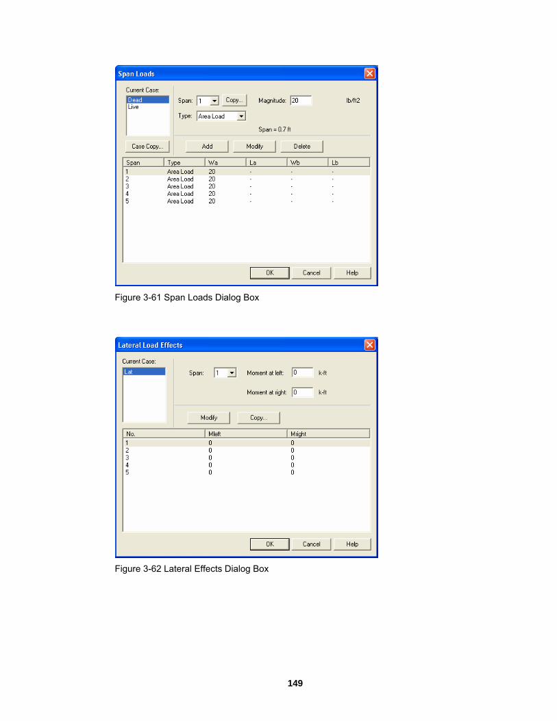
Figu 3
re -61 Span Loads Dialog Box
Figure 3-62 Lateral Effects Dialog Box
149

ProgramOutput Dial
Output Dialog Windows og Windows
Figu
re 3-63 Result Report
150

Ch. 4 Operating the Program Working with Data Files (menu File) Creating N
When y you will have a new file ready for input. The data will not hav fnew data file is created after the "pcaSlab1", the new data file will be named as "pcaSla
To sta
a ew Data File
ou first load pcaSlabe a ilename associated with it, therefore, "pcaSlab1" will appear in the title bar. If a
b2", and so on.
rt a new data file:
1. If you are already in the program and in an existing file, select New button or New menu command to clear your screen and return you to the default settingIf existin
s. g data has been changed prior to executing the New command, pcaSlab
2.
g boxes necessary to design your floor system. You may
3. ut menu, use the Save As command to give
Opening Existing Data File pcaSla
To op
1. Select Open command from the File menu or click the Open button
will ask if you would like to save the data. After New is selected, Auto Input command in the Input menu may be used. This command guides you through the inputting process by automatically displaying all the dialocancel the auto input mode by selecting Cancel button from any dialog box. After you enter data through the Inpthe file a name.
b allows you to open data files that were saved at an earlier time.
en an existing data file:
to bring in an e pcaSlab data file. The dialog box of Figure 4-1 will be displayed. All the files with an .slb extension contained in the current drive and directory will be displayed in the list box. This dialog box als les you to cha e the current drive and directory.
xisting
o enab ng
151

Figure 4-1 Open Dialog Box
2. open. You may also select a file from the
provided list with the mouse or using the keyboard by tabbing to the list and
3. w pcaSlab to read the data. You may
Importin pca b
To open an existing ADOSS data file:
Type in the name of the file you want to
using the up and down arrow keys. Press Open to exit the dialog box and allocombine steps 2 and 3 of this procedure by double clicking the left mouse button over the desired file from the provided list.
g ADOSS Data File
Sla allows you to open ADOSS data files that were saved at an earlier time.
1. Select Open command from the File menu or click the Open button to bring in an existing ADOSS data file. The dialog box of Figure 4-2 will be displayed. All
an .ads extension contained in the current drive and directory will be displayed in the list box. This dialog box also enables you to change the current
the files with
drive and directory.
152

Figure 4-2 Importing ADOSS data file Dialog Box
2. ay also select a file from the
provided list with the mouse or using the keyboard by tabbing to the list and using the up and down arrow keys.
Noe of a
2. tem models developed in ADOSS are supported by pcaSlab.
Saving the
To save your data with the same filename:
1. Select the Save command from the File menu or simply click the Save button
Type in the name of the file you want to open. You m
3. Press Open to exit the dialog box and allow pcaSlab to read the data. You may combine steps 2 and 3 of this procedure by double clicking the left mouse buttonover the desired file from the provided list.
te: 1. The extension name of an ADOSS file is .ADS, while the extension nam
pcaSlab file is .SLB. Only two-way sys
Data File
. If the data has not been modified since the last save or Save As command s executed, this option will not be available. The file will be updated and the ve command and button will be shaded gray.
o give your data a new filename:
e
waSa
T
1. If you have not saved your data yet, select the Save or Save As command fromthe File menu. Either command will have the same effect. If you would like to save a data file that currently has a filename with a new filename, select the Save As command. The dialog box of Figure 4-3 will appear. When no filenamhas been given to the current data, the default filename is "pcaSlab1.slb", and it
153

is highlighted in the edit box.
Figure 4-3 Save As Dialog Box
2. Type a new name to overwrite the current name. 3. Press Save to exit the dialog box and save the data into the filename specified.
Most Recently Used Files (MRU)
Figure 4-4 Most Recently Used File List (MRU)
The Most Recently Used Files (MRU) list shows the four data files that were opened most recently. Selecting a data file from this list makes it easier and faster to open the file. The list is empty when the program is executed for the first time.
154

SpecifyingData Input Wiz
Data Input Wiza
The Data In igned to make the inputting process easier. By selecting the
Data Input
the Model Data (menu Input) ard
rd
put Wizard is des
Wizard from Input Menu or selecting from the tool bar, a logical f dialog boxes will automatically be displayed allowing you to enter data for stem.
sequence oyour floor sy
Genera form
Defining Genera The Generadatabase, ru he input process. You must choose this command before doing any further inputting since this command affects the availability of the commands in the Input menu.
ation:
l In ation
l Information
l Information command allows you to enter labels, design code, rebar n mode, and the frame information needed by pcaSlab to proceed with t
o enter general informT
1. Select the General Information command from the Input menu or click the button from the tool bar. The dialog box of Figure 4-5 will appear.
155

Figure 4-5 General Information Dialog Box
lt nd
fore the minimum number of supports is 2 and the
6. nd/or Right cantilever check boxes if left cantilever
7.
f the Next button to the next dialog box.
Defining Material Properties
other is for reinforcing steel. This command must be xecuted in order to perform a design of the floor system. Use the tab key to get to each
edit box then type in your values, or use your mouse and click directly on the desired tab
2. Enter the project name, frame name, and engineer name in the Label frame box. 3. Select the building standard you want your floor system to be designed to (ACI
318-99, ACI 318M-99, CSA-A23.3-94, CSA-A23.3-94E) from the Option frame box.
4. Select the Design or Investigation from the Run mode frame box. 5. In the Frame frame box, enter the Number of supports of the frame. The defau
number of supports is 2. The minimum and maximum number of spans are 1 a20 spans, respectively. Theremaximum number of supports is 21. Check the Left cantilever aand/or right cantilever exists in the frame respectively. Check the Distance location as ratio of span if the locations of loads need to be entered as a ratio of the length of a span.
8. Press Ok button to exit the dialog box and allow pcaSlab to use the new data. Iusing the Auto Input, click
Material Properties
The Material Properties command from the Input menu allows you to input material properties of the concrete and the reinforcement. There are two tabs in this dialog box. One is for concrete and thee
156

and box, then type in your explanation of the default v
values. Refer to "Material Properties" for a detailed alues.
To
1. Select the Material Properties command from the Input menu or click the
define material properties:
button on the tool bar. The dialog box of Figure 4-6 will appear.
Figure 4-6 Concrete Properties Dialog Box
cally be computed for the slabs, beams, and columns. Young’s modulus ding text boxes.
on average split tensile strength of concrete, which is calculated internally by the program. These values will be used for deflection analysis. A large value for the rupture
ysis based on gross, non-cracked, sections. The CSA A23.3-94 Standard requires that for the calculation of slab
2. Concrete tab and enter the concrete density for the following members: Slabs, Beams, and Columns. Enter the concrete compressiv
Click the
3. e strength. By entering a value for the compressive strength, values for Young’s modulus and rupture modulus will automatiand rupture modulus will automatically be shown in the correspon
4. If you have values for the rupture modulus, enter the values in the text boxes for the slabs, beams, and columns. Default values are computed based
modulus will produce a deflection anal
deflections a rupture modulus value equal to 2/f6.0 'c be used. pcaSlab
defaults to this value of the rupture modulus for the slab concrete in CSA designruns.
5. Click the Reinforcing Steel tab as shown in Figure 4-7.
157

Figure 4-7 Reinforcing Steel Properties dialog box
6. Enter the yield stress of flexure steel. 7. Enter the yield stress of stirrups. 8. Enter the Young’s modulus for flexural steel and stirrups. 9. Select whether the main reinforcement is epoxy-coated by clicking the left mouse
button on the box or tabbing to the box and pressing the space bar. This selection affects development lengths.
10. Press Ok button to exit the dialog box so that pcaSlab will use these material properties. If using the Auto Input, click the Next button to the next dialog box.
Spans
Defining the Slabs The Spans command from the Input menu is available for all floor systems. Span numbers, which are determined from the number of supports entered in the General Information box, are automatically filled into the Span drop-down list in the Span Data dialog box.
To input slab geometry:
1. e Spans command from the Input menu or click the
Select th button on the
tool bar. Click the left mouse button on the Slabs tab. The dialog box of Figure 4-8 will appear.
158

Figure 4-8 Defining the Slabs dialog box
2. Select the number of the span, for which dimensions will be entered, from the
Span drop-down list. om the Location drop-down list. Three types of
locations are available: Interior, Exterior Left, and Exterior Right. The "left" and as
a
design strip, it should be an "Exterior Right" span. the span.
m column centerline to column centerline or edge to column centerline for the two cantilever spans in the Length edit box. If the
6. Enter the span design width in the transverse direction of analysis on the left and right side of the column (see Figure 4-9). These distances are usually one-half the distance to the next transverse column or edge of the slab for exterior spans. The left and right designations are arbitrary. Both interior and exterior spans may be used in a design strip. An exterior width will automatically be designated by pcaSlab by entering a width value less than or equal to the transverse column dimension. Exterior sides do not contribute to the attached torsional stiffness, although they do contribute to loading. pcaSlab will use the total width entered for weight and superimposed loading but will use code allowed dimensions for flange width and stiffness computations.
3. Select the span location fr
"right" are defined as you look along the direction of analysis. If a span hdesign strips on both sides it should be an "Interior" span. If a span has only left design strip, it should be an "Exterior Left" span. If a span has only a right
4. Enter the slab thickness of5. Enter the span length fro
program detects a cantilever span length less than one-half the column dimension in the direction of analysis, an error message will pop up when the frame is analyzed. If a partial load is affected by the span length, a message warns the user of this condition.
159

Figure 4-9 Required Slab Dimensions
7. ometry. 8. Repeat steps 2 through 7 until all the spans have been updated. You can use the
9. n to exit the dialog box and allow pcaSlab to use the updated slab
Defining Longitu quired for the beam-supported slab. Span numbers, whibox
-supported slab system:
Press the Modify button to update the slab ge
Copy button as a shortcut. Press Ok buttogeometry.
the Longitudinal Beams
dinal beam dimensions are rech are determined from the number of supports entered in the General Information , are automatically filled into the Span drop-down list.
To input geometry for beam
1. Select the Spans command from the Input menu or click the button on the tool bar. Click the left mouse button on the Longitudinal Beams tab. The dialog box of Figure 4-10 will appear.
160

Figure 4-10 Longitudinal Beam Geometry Dialog Box
2. rop-down list. 3. Enter the width of the beam (Figure 4-11).
Select the span number from the Span d
Figure 4-11 Required Longitudinal Beam Dimensions
4. Enter the depth of the beam from the top of the slab (Figure 4-11). 5. Press the Modify button to update the longitudinal beam geometry. 6. Repeat steps 2 through 6 until all the beams have been updated. You can use
161

the Copy button as a shortcut. 7. Press Ok button to exit the dialog box so that pcaSlab will use the new beam
Defining the Ribs
be
o enter rib geometry:
1. Select the Spans command from the Input menu or click the
geometry.
For the waffle slab system, you must define the rib geometry. The ribs are assumed tothe same throughout the strip.
T
button on the tool bar. Click the left mouse button on the Ribs tab. The dialog box of Figure 4-12 will appear.
Figure 4-12 Ribs Geometry Dialog Box
2. Select the span number from the Span drop-down list. 3. Enter the spacing between ribs at the bottom for clear rib spacing (see Figure
4-13).
162

Figure 4-13 Required Rib Dimensions
4. Enter the width at the bottom for rib width (see Figure 4-13).
h (see Figure 4-13). can use the rib geometry.
Defini
specified at the joints the joint is assumed umn dimensions above and below.
To
1.
5. Enter the depth of the rib below the slab for Rib dept6. Press Ok button to exit the dialog box so that pcaSlab
Supports
ng the Columns Column data is optional. If no column ishinged. You will be allowed to enter col
input column/capital geometry:
Select the Supports command from the Input menu or click the button othe tool bar. The dialog box of Figure 4-14 will a
n
ppear. Click on the Columns tab.
163

Figure 4-14 Column Geometry dialog box
2. Enter the column height above, which is the distance from the top of the design
gure 4-15). pcaSlab obtains the clear ove by subtracting the average slab depth from the height
given. Only the slab is considered for the floor system above. A zero dimension
floor to the top of the floor above (see Ficolumn height ab
for the column heights above and below will create a pin condition.
Figure 4-15 Required Column Dimensions
164

3. Enter the column height below, which is the distance from the design floor to the
w (see Figure 4-15). To obtain a clear column height below, rop/beam depth is subtracted from the height given. A zero dimension
4.
5. Enter a value for c olumn dimension perpendicular to the direction of analysis (see Figure 4-15). Round columns are specified with a zero input for c2; c1 is then taken as the diameter. Zero value for Stiffness Share will create a pin
6. Press the Modify button to update the slab geometry. needs
8. Repeat steps 2 through 7 until all the columns and capitals have been updated. button as a shortcut. the dialog box so that ADOSS will use the new data.
Defining the
rops are only available for the flat slab or waffle slab systems and can be defined at all the support locations. The drop length and width dimensions are computed by pcaSlab, based o " is selected in the Type drop-down list.
To
top of the floor belothe slab/dfor the column heights above and below will create a pin condition. Enter a value for c1, the column dimension in the direction of analysis (see Figure 4-15).
2, the c
condition.
7. Check the Check punching shear around column if the punching shear to be checked.
You can use the Copy 9. Press Ok button to exit
Drop Panels
D
n slab span dimensions, when the "Standard
input drop geometry
the 1. Select the Supports command from the Input menu or click button then click on the Drop Panels tab. The dialog box of Figure 4-16 will appear.
165

Figure 4-16 Drop Geometry Dialog Box
2. Select whether pcaSlab should compute the drop dimensions or the dimensions
will be user specified. If pcaSlab is to compute the dimensions, the "Standard" option should be selected from the Type drop-down list and then only the drop depth will be available. When the "Standard drop" option is selected pcaSlab will
ACI 318-99 Clause 13.3.7. Similar requirements contained in previous editions of the CSA A23.3 Standard have been removed from the 1994 edition. As a result, the ACI minimum
uns when the cify drop dimensions
other than those computed by pcaSlab, you must select "User-defined" from the Type drop-down list.
3. Enter the dimension in the direction of analysis from the column centerline to the edge of the drop left of the column (see Figure 4-17). If this is a standard drop, this dimension will not be available and the length left is set equal to the slab span length left/6 for interior columns or the left cantilever length for the first column.
calculate drop panel dimensions in accordance with
specifications for drop panels are also used in CSA A23.3 r"Standard Drops" option is selected. If you would like to spe
166

Figure 4-17 Required Drop Dimensions
4. direction (see Figure 4-17). If this is a
standard drop, this dimension will not be available and the width is set equal to slab width/3.
e e
6. y button to update the drop geometry. 7. Repeat steps 2 through 6 until all the drop dimensions have been updated. You
can use the Copy button as a shortcut. 8. Press will use the new drop
Enter the width dimension in the transverse
5. In order for pcaSlab to recognize drops, drop depths are required for the flat slabsystems even if Standard Drop is selected. Enter the depth of the drop from thspan with the smaller slab depth (see Figure 4-17). For waffle slab systems, thdepth is automatically assumed to be equal to the rib depth below the slab and is not displayed. A value entered will be considered to exist below the rib depthduring calculations. Press the Modif
Ok button to exit the dialog box so that pcaSlabgeometry.
167

Defining the Column Capitals
To input column capital geometry:
1. Select the Supports command from the Input menu or click the
button on the tool bar. Click left mouse button on the Column Capitals tab to activate it. The dialog box of Figure 4-18 will appear.
Figure 4-18 Capital Dimensions
2. Select the support number from the Support drop-down list.
Enter the capital depth which is the distance from the bottom of the soffit (slab,drop, or beam), to the bottom of the capital. The Side slope is the rate of depth to extension of the capital and it must be less than 1 and smaller than 50 (see Figure 4-19).
3.
4.
168

Figure 4-19 Required Capital Dimensions
5. Enter the capital extension which is the distance from the edge of the column to
the end of the capital (see Figure 4-19).
Defining the Transverse Beams The Transverse Beam command allows you to input the width, depth, and offset (eccentricity) of transverse beams at each column. This command is not available for the one-way slab systems and it is optional for the remaining systems.
o input transverse beam geometry:
1. tab
T
Select the Support command from the Input menu. Select Transverse Beamsfrom the Support Data dialog box. The dialog box of Figure 4-20 will appear.
169

Figure 4-20 Transverse Beam Geometry dialog box
2. Enter the width of the transverse beam (see Figure 4-21)
Top of Slab
DepthWidth
Ecc.
Beam
n
CL
CLColum
Figure 4-21 Required Transverse Beam Dimensions
the top of the slab to
4. Enter the eccentricity, which is measured from the joint centerline, positive to the
3. Enter the depth of the transverse beam which is taken fromthe bottom of the beam (see Figure 4-21)
170

right, and negative to the left of the joint (See Figure 4-21). 5. Press the Modify button to update the transverse beam dimensions.
2 through 5 until all the beams have been updated. You can use the Copy button as a shortcut (see "Entering the Structure Geometry" earlier in
help on the Copy button). 7. Press Ok button to exit the dialog box so that pcaSlab will use the new beam
Reinforcement Criteria
Defining the Reinforcement Criteria for Slabs and Ribs In oreinforc ions. See "Area of
einforcement" and "Reinforcement Selection" in Method of Solution for a discussion of the reinfo ement computations.
o define reinforcement Criteria for Slabs and Ribs:
1. e
6. Repeat steps
this chapter for
geometry.
rder for pcaSlab to select the reinforcement, you must define the slab and rib ement, bar sizes, location, and minimum spacing dimens
Rrc
T
Select the Reinforcement Criteria command from the Input menu or click th
button on the tool bar. Select Slabs and Ribs tab by clicking the left mouse button on the tab title. The dialog boxes of Figure 4-22 will appear.
Figure 4-22 Slab and Rib Reinforcement Dialog Boxes
171

2. For slabs and ribs, enter the clear covers for top and bottom reinforcing bars. For
the top reinforcement, this distance is from the top of the slab to the top of the top bars. For the bottom reinforcement, this distance is from the bottom of the slab to the bottom of the bottom bars (see Figure 4-23). The default value is 1.5 in. (40mm) for both input items.
Figure 4-23 Distance to Reinforcement Edges
3.
4. tion
5. Enter minimum bar spacing for slab and rib flexural reinforcement. This number should be based on aggregate size or detailing considerations. Default spacing is
bs and ribs. ar spacing for slab and rib flexural reinforcement. Default
r slab and rib flexural reinforcement. Default ratio is 0.2% for slabs and ribs. If the user specified value is smaller than
the top bars have more than 12 in. of concrete below them, check the corresponding check box.
llow pcaSlab to use the new data.
Enter the minimum bar size to start the iteration for determining flexural reinforcement. Enter the maximum bar size. This number will be used as a stop in the iterafor determining flexural bars in beams.
6 in. (150mm) for sla6. Enter maximum b
spacing is 18 in. for slabs and ribs. 7. Enter minimum Reinforcement Ratio fo
0.18, 0.18 is used by pcaSlab. If the user specified value is greater than 0.18, the specified value is used by pcaSlab.
8. Enter maximum Reinforcement Ratio for slab and rib flexural reinforcement. Default ratio is 2% for slabs and ribs.
9. If
10. Press Ok button to exit the dialog box and a
172

Defining the Reinforcement Criteria for Beams In order st define the beam reinforcement sions. See "Area of
einforcement" and "Reinforcement Selection" in the Method of Solution for a discussion of th e
To def
1. Select the Reinforcement Criteria command from the Input menu or click the
for pcaSlab to select the reinforcement, you mu, bar sizes, location, and minimum spacing dimen
Re r inforcement computations.
ine reinforcement criteria for beams:
button on the tool bar. Select Beams tab by clicking the left mouse button on
the tab title. The dialog boxes of Figure 4-24 will appear.
Figure 4-24 Reinforcement Dialog Boxes
2. Enter the covers for top and bottom reinforcing bars for beams. For the top
ce is from the top of the slab to the centroid of the top reinforcement, this distance is from the bottom of the
slab to the centroid of the bottom bars (see Figure 4-25). The default value is 1.5
reinforcement, this distanbars; and for the bottom
in. (40mm) for both input items.
173

Figure 4-25 Distance to Reinforcement
3. Enter the minimum bar size for top and bottom bars and stirrups to start the
iteration for determining flexural reinforcement. 4. Enter the maximum bar size for top and bottom bars and stirrups. his number
mining flexural bars in beams. 5. Enter the minimum bar spacing for beam flexural reinforcement and stirrups. This
number should be based on aggregate size or detailing considerations. The
6. Enter the maximum bar spacing for beam flexural reinforcement and stirrups. The default maximum reinforcement spacing is 18 in. and the default maximum stirrup spacing is 18 in.
7. ral reinforcement. Default ratio is 0.2% for beams. If the user specified value is smaller than 0.2, 0.2 is used by pcaSlab. If the user specified value is greater than 0.2, the specified value is
8.
10. x and allow pcaSlab to use the new data.
Reinforcing
Defining Column Strip Bars
ber of bars, bar length, etc. can be defined by users if the selected in the General Information dialog box. This menu
em is not available if Run Mode of Design is selected in the General Information dialog
Twill be used as a stop in the iteration for deter
default minimum reinforcement bar spacing is 2 in. and the default stirrup spacing is 6 in.
Enter the minimum Reinforcement Ratio for beam flexu
used by pcaSlab. Enter the maximum Reinforcement Ratio for beam flexural reinforcement. Default ratio is 2% for slabs and ribs.
9. If the top bars have more than 12 in. of concrete below them, check the corresponding check box. Press Ok button to exit the dialog bo
Bars
The reinforcing bar size, numRun Mode of Investigation isitbox.
174

To define column strip bars:
1. Select Reinforcing bars from the Input menu or click the button on the tool bar. Select the Column Strip Bars tab by clicking the tab title or use the tab key on the keyboard to toggle to the tab title then select the Column Strip Bars tab
oxes of Figure 4-26 will appear. using the arrow keys. The dialog b
Figure 4-26 Defining Column Strip Bars
Select the sp
2. an for which reinforcing bars will be defined from the Span list box
3. -down list.
5. einforcing bars by entering the length in the Length
6. Define the types of the reinforcing bars in the selected span by selecting from the Type drop-down list, which is right below the Bar Size drop-down list. Five types are available: Top Left, Top Right, Top Continuous, Bottom Continuous and
s. 7. Define the cover by entering the number in the Cover input box. The unit of
e
on the upper left corner. The length of the selected span will be shown right above the Add button. Select bar size from the Bar Size drop
4. Define the number of reinforcing bars in the selected span by entering the number in the Number of Bars input box. Define the length of the rinput box. The unit of the length is foot.
Bottom Discontinuou
cover is inch. 8. Press Add button to add the new data into the list box below the buttons. 9. Repeat steps 2 to 8 to define reinforcing bars for all the spans. You may use th
Span Copy button below the Span list to simply copy the data of one span to other spans.
175

10. If the reinforcing data of a span needs to be modified, select the data from the er part of the dialog box then modify the data as s Modify button when finished to update the
corresponding data in the data list box. r
12. Press Ok button to exit the dialog box so that pcaSlab will use these reinforcing bar properties.
Defining Middle Strip Bars The reinforcing bar size, number of bars, bar length, etc., can be defined by users if the Run Mode of Investigation is selected in the General Information dialog box. This menu item is not available if Run Mode of Design is selected in the General Information dialog box.
To define middle strip bars:
1. Select Reinforcing bars from the Input menu or click the
data list box on the lowmentioned above. Pres
11. To delete the reinforcing data for a span, select the data of the span f om the data list box then press the Delete button.
button on the tool bar. Select the Middle Strip Bars tab by clicking the tab title or use the tab key on the keyboard to toggle to the tab title then select the Middle Strip Bars tab using the arrow keys. The dialog boxes of Figure 4-27 will appear.
Figure 4-27 Defining Middle Strip Bars
reinforcing bars will be defined from the Span list box
2. Select the span for which
176

on the upper left corner. The length of the selected span will be shown right
rop-down list. 4. Define the number of reinforcing bars in the selected span by entering the
5. in the Length input box. The unit of the length is foot.
6. Define the Types of the reinforcing bars in the selected span by selecting from the Bar Size drop-down list. Five types
Continuous, Bottom Continuous and Bottom Discontinuous.
8. Press Add button to add the new data into the list box below the buttons. 9. Repeat steps 2 to 8 to define reinforcing bars for all the spans. You may use the
Span Copy button below the Span list to simply copy the data of one span to other spans.
10. If the reinforcing data of a span needs to be modified, select the data from the data list box on the lower part of the dialog box then modify the data as mentioned above. Press Modify button when finished to update the corresponding data in the data list.
11. To delete the reinforcing data for a span, select the data of the span from the data list box then press the Delete button.
12. Press Ok button to exit the dialog box so that pcaSlab will use these reinforcing
Defining The rein ize, number of bars, bar length, etc. can be defined by users if the Run Moitem nbox.
To def
1. from the Input menu or click the
above the Add button. 3. Select bar size from the Bar Size d
number in the Number of Bars input box. Define the length of the reinforcing bars by entering the length
the drop-down list, which is right below are available: Top Left, Top Right, Top
7. Define the cover by entering the number in the Cover input box. The unit of cover is inch.
bar properties.
Beam Bars
forcing bar sde of Investigation is selected in the General Information dialog box. This menu
is ot available if Run Mode of Design is selected in the General Information dialog
ine beam bars:
Select Reinforcing bars button from the on
the keyboard to toggle to the tab title then select the Beam Bars tab using the arrow keys. The dialog boxes of Figure 4-28 will appear.
tool bar. Select the Beam Bars tab by clicking the tab title or use the tab key
177

Figure 4-28 Defining Beam Bars
2. Select the span for which reinforcing bars will be defined from the Span list box
on the upper left corner. The length of the selected span will be shown right above the Add button.
3. Select bar size from the Bar Size drop-down list. Define the number of reinforcing bars in the selected span by entering the 4.
e length in the Length input box. The unit of the length is foot.
6. Define the types of the reinforcing bars in the selected span by selecting from the right below the Bar Size drop-down list. Five types
are available: Top Left, Top Right, Top Continuous, Bottom Continuous and Bottom Discontinuous.
Press Add button to add the new data into the list box below the buttons. 9. Repeat steps 2 to 8 to define reinforcing bars for all the spans. You may use the
an list to simply copy the data of one span to other spans.
11. an, select the data of the span from the data list box then press the Delete button.
12. Press Ok button to exit the dialog box so that pcaSlab will use these reinforcing
number in the Number of Bars input box. 5. Define the length of the reinforcing bars by entering th
Type drop-down list, which is
7. Define the cover by entering the number in the Cover input box. The unit of cover is inch.
8.
Span Copy button below the Sp
10. If the reinforcing data of a span needs to be modified, select the data from the data list box on the lower part of the dialog box then modify the data as mentioned above. Press Modify button when finished to update the corresponding data in the data list. To delete the reinforcing data for a sp
bar properties.
178

Defining Bea
To
1. Select Reinforcing bars from the Input menu or click the
m Stirrups
define beam stirrups:
button from the tool bar. Select the Beam Stirrups tab by clicking the tab title or use the tab key on the keyboard to toggle to the tab title then select the Beam Stirrups tab using
arrow keys. The dialog boxes of Figure 4-29 will appear. the
Figure 4-29 Defining Beam Stirrups
2. Select the span for which stirrups will be defined from the Span list box on the
upper left corner. The length of the selected span will be shown right above the Add button.
3. Enter the amount of stirrups of the selected span in the Count input box. (see Note)
4. Select stirrup size from the Size drop-down list. 5. Enter the spacing of the stirrups of the selected span in the Spacing input box.
The unit of spacing is inch. 6. Enter the number of legs in the Leg input box. 7. Press Add button to add the new data into the list box below the buttons. 8. Repeat steps 2 to 8 to define stirrups for all the spans. You may use the Span
Copy button below the Span list to simply copy the data of one span to other spans.
179

9. If the stirrup data of a span needs to be modified, select the data from the data list box on the lower part of the dialog box then modify the data as mentioned above. Press Modify button when finished to update the corresponding data in the data list.
10. To delete the stirrup data for a span, select the data of the span from the data list box then press the Delete button.
11. Press Ok button to exit the dialog box so that pcaSlab will use these reinforcing bar properties.
Note:
If stirrups do not apply in a part of a span, the Count should be set to 0 (zero) and the Spacing should be the length of the part of the span where no stirrups are defined. For example, the following configuration shows stirrups in the left and right ends of a span with an empty space (46.0 in. long, no stirrups) in the middle part of the span.
Count Bar Size Spacing Legs
32 #5 4.56 2
0 #5 46.0 2
32 #5 4.56 2
oad Cases
oad, live load or lateral load can be defined in the Load ases dialog box. The default three load case labels (types) are SELF (dead load), Dead
d load) and Live (live load).
enu or click the
L
Defining Load Cases Up to 6 load cases of dead lC(dea
To define load cases:
1. Select Load Cases command from the Input m button on the tool bar. Figure 4-30 will appear.
180

Figure 4-30 Define Load Cases
2
3. Select the type of the new load case from the Type drop-down list. The available types are Dead Load, Live Load and Lateral Load.
nce the maximum number is reached, the Add button will be
disabled.
d press the Modify button.
7. To delete an existing load case, select the load case from the load case list box
8. Press Ok button to exit the dialog box so that pcaSlab will use these load cases.
Note: 12. Load case label must be unique for each of the load cases.
. Enter a name for the new load case in the Label edit box. The name could be any character string defined by the user.
4. Press the Add button to add the new load case into the load case list box on thelower part of the dialog box.
5. Repeat steps 2 to 4 to define all the load cases. The maximum number of loadcases is 6. O
6. To modify an existing load case, select the load case from the load case list box then change the label or type the selected load case as mentioned above an
then press the Delete button.
. Only one case of live load can be defined.
181

Load Combinations
Defining Load Combinations
pca he efault values depend on the code selected with the General Information command.
To def
Slab allows you to change the magnification factors applied to the load cases. T
d
ine load factors:
1. Select Load Combinations from the Input menu or click the button from thetool bar. The dialog box of Figure
4-31 will appear if the ACI code was selected in the General Information dialog box.
Figure 4-31 Define Load Combinations
2. The load cases and the corresponding factors that are defined in the Load
Cases dialog box are shown on the top of the Load Combinations dialog box. 3. Enter the load factors for each of the load cases in the input box below the
corresponding load case label. 4. Press the Add button to add the combination defined above into the big list box
in the lower part of the dialog box. 5. Repeat steps 2 to 4 to define all the load combinations. Up to 12 load
combinations may be defined. All the combinations are indexed automatically from U1 to U12.
6. To change the factors of an existing combination, select the load combination from the load combination list box on the lower part of the dialog box then
182

change the factors as mentioned above. Press the Modify button when finished to update the data in the load combination list box.
7. To delete an existing combination, select the load combination from the load combination list box then press the Delete button.
8. Select Ok button when all the desired load factors have been modified to exit so that pcaSlab will use the new data.
Span Loads
About Loads
o complete your analysis of a floor system, you must specify the applied loads. pcaSlab com ds that ma enu. Surface loads are placed over the rand conChasys .modifie The Fig g is a description of that input.
Tputes the self weight of the floor system. There are several types of applied loa
y be entered. They are found in the Input menti e strip. Partial loads consist of uniform or trapezoidal loads, concentrated loads,
centrated moments that may exist anywhere within the span length. Refer to r 2 "Loading" for a detailed explanation of the superimposed loading on the floorpte
tem Up to 6 load cases can be defined by users and the default load factors can be d by users too.
ure 4-32 shows the input required and the followin
Figure 4
-32 Required Partial Load Data
183

W
downward. For trapezoidal loads, Wa is the weight at the left end in
a For uniform loads, Wa is the uniform load in units of lbs/ft (kN/m), positive Wa isunits of lbs/ft (kN/m), positive Wa is downward. For concentrated loads, Wa is the force in units of kips (kN), positive Wa is downward, and for moments, Wa is the moment in units of ft-kips (kN-m), positive Wa is clockwise.
Wb For trapezoidal loads, Wb is the weight at the right end in units of lbs/ft (kN/m), positive Wb is downward. For all the other partial load types, Wb is not available.
La For uniform and trapezoidal loads, La is the distance where the load begins from the centerline of the column at the left of the span, in units of ft (m). For concentrated loads and moments, La is the distance where the load exists from the centerline of the column at the left of the span in units of ft (m).
Lb For uniform and trapezoidal loads, Lb is the distance where the load ends from the centerline of the column at the left of the span, in units of ft (m). For concentrated loads and moments, Lb is unavailable. Although the particular loading may not actually act over the entire transverse width, all line loading is converted internally by pcaSlab to act over the full width of the slab. In the design direction, partial loads given as acting over less
an 1/20 of the span length will be averaged over 1/20 by the program. th
Defini
(kN/m2). The method for inputting area loads is the same as that used in entering the geometry.
To input area loads:
ng Area Load on Span Area loads are uniform loads acting over the entire strip. These loads have units of lb/ft2
1. Select the Span Loads command from the Input menu or click the button onthe tool bar. Select the Area Load from the Type drop-down list on
the Span
Loads dialog box. The dialog box of Figure 4-33 will appear.
184

Figure 4-33 Define Area Load on Span
Current Case list box on the upper left corner as
3. Select the span on which the area loads will be applied from the Span drop-down list.
sed area load magnitude acting over the entire
6. Repeat steps 2 through 5 until the loads have been updated. You can use the Copy button as a shortcut.
7. To change the data of an existing area load, select the area load from the area magnitude as mentioned above. Press the Modify
in the area load list box. 8. To delete an existing area load, select the load from the area load list box then
ox so that pcaSlab will use the new data.
Defining Line Load on Span You ma dal loads that do not span from column centerline to olumn centerline in the direction of analysis. These loads are called line loads and are
input through the Span Loads dialog of the Input menu. Partial loads are assumed to act over the entire strip width.
2. Select the load case from the
shown in the dialog above.
4. Enter the un-factored superimpoarea of the strip in the Magnitude edit box. Positive surface loads act downward.
5. Press the Add button to update the area loads in the area load list box on the lower part of the dialog box.
load list box then change the button when finished to update the data
press the Delete button. 9. Press Ok button to exit the dialog b
y enter uniform or trapezoic
185

To input line loads:
1. Select the Span Loads command from the Input menu or click the button on the tool bar. Select the Line Load from the Type drop-down list. The dialog box of Figure 4-34 will appear.
Figure 4-34 Defining Line Load on Span
2. Select the load case of the line load that will be defined from the Current Case
list box. 3. From the Span drop-down list, select the span number of the span whose line
loads you would like to input. 4. Define un-factored load values and their locations in the corresponding text
boxes. 5. Select Add to add the line load defined into the line load list box. 6. Repeat steps 2 through 5 until all the line loads have been entered then press Ok
button to exit the dialog box so that pcaSlab will use the new loads.
To change line loads data:
1. Select the line load you want to change from the line load list box on the lower part of the dialog box by clicking the left mouse button on the load or tabbing to the list box and using the arrow up and down keys.
2. Make your changes to the load by modifying the load type, the load magnitude, and/or location.
3. Select Modify to replace the old data with the new data.
186

To delete line load data:
1. Select the line load you want to delete from the line load list box by clicking the left mouse button on the load or tabbing to the list box and using the arrow up
Defini
ted vertical loads. These loads are input through the Span Load ut menu. Point loads are assumed to act over the entire strip width.
command from the Input menu or click the
and down keys. 2. Press the Delete button.
ng Point Force on Span You may enter concentracommand of the Inp
To input point loads:
1. Select the Span Loads button on the tool bar. Select the Point Force from the Type drop-down list. The dialog box of Figure 4-35 will appear.
Figure 4-35 Defining Point Forces on Span
Span drop-down list, select the span number of the span whose point loads you would like to input.
2. Select the load case of the point force that will be defined from the Current Case
list box. 3. From the
187

4. Define un-factoredboxes.
load values and their locations in the corresponding text
6. Repeat steps 2 through 5 until all the point loads have been entered then press Ok button to exit the dialog box so that pcaSlab will use the new loads.
t load list box by clicking the left mouse button on the load or tabbing to the list box and using the arrow up and down keys.
ur changes to the load by modifying the load type, the load magnitude, cation.
1. Select the point force you want to delete from the point load list box to the right he left mouse button on the load or tabbing to the list box and using
the arrow up and down keys.
Defini
ommand of the Input menu. Point moments are assumed to act over the entire strip idth.
5. Select Add to add the point load defined into the point load list box on the lower part of the dialog box.
To change point load data:
1. Select the point force you want to change from the poin
2. Make yoand/or lo
3. Select Modify to replace the old data with the new data.
To delete point load data:
by clicking t
2. Press the Delete button.
ng Point Moment on Span You may enter concentrated moment. This load is input through the Span Load cw
To input point moments:
1. Select the Span Loads command from the Input menu or click the button othe tool bar. Select the Point Moment from the Type drop-down list. The dialogbox of Figure 4-36 will appear.
n
188

Figure 4-36 Defining Point Moments on Span
3. From the Span drop-down list, select the span number of the span whose point moments you would like to input.
moment values and their locations in the corresponding text
on the
.
load data:
ou want to change from the point moment list box by clicking the left mouse button on the load or tabbing to the list box and using the arrow up and down keys.
nges to the moment by modifying the moment type, the moment /or location.
x to the and
2. Select the load case of the point moment that will be defined from the Current
Case list box.
4. Define un-factored boxes.
5. Select Add to add the point moment defined into the point moment list box lower part of the dialog box.
6. Repeat steps 2 through 5 until all the point moments have been entered then press Ok button to exit the dialog box so that pcaSlab will use the new moments
To change point
1. Select the point moment y
2. Make your chamagnitude, and
3. Select Modify to replace the old data with the new data.
To delete point load data:
1. Select the point moment you want to delete from the point moment list boright by clicking the left mouse button on the load or tabbing to the list box using the arrow up and down keys.
189

2. Press the Delete button.
Latera
Defining Lateral Effects
ad analysis with a lateral load analysis. Lateral loads the
1. Define at least one lateral load case from the Load Cases dialog box.
ects from the Input menu. If no lateral case is defined this ce selected, Figure 4-37 will appear.
l Effects
pcaSlab combines the gravity lomay be entered as joint moments depending on the type of lateral load selected inGeneral Information dialog box. These moments must be obtained by a frame analysis. The joint moments are combined with the gravity load moments to produce load patterns 5 through 8.
To input lateral load moments:
2. Select Lateral Effcommand is disabled. On
Figure 4-37 Lateral Moment Dialog Box
3. Select load cases from the Current Case list box. At least one lateral load case
must be defined in the Load Cases dialog box before you can see the load cin the Current Case list box.
4. Select span number on which lateral loads will be defined from the Span drop-down list.
ase
5. Enter the moments at the left end and right end of the span in the Moment at
190

Left and Moment at Right input boxes, respectively. 6. Press the Add button to add the lateral load defined above into the lateral load
list box in the lower part of the dialog box. 7. Repeat steps 2 through 5 to define all the lateral loads. 8. To change an existing lateral load, select the load from the lateral load list box
then change the moments as mentioned above. Press the Modify button when in the lateral load list box.
teral load, select the load from the lateral load list box
exit so
Executing the Calculations (menu Solve) Solve
l
t
finished to update the data 9. To delete an existing la
then press the Delete button. 10. Select Ok button when all the desired lateral loads have been modified to
that pcaSlab will use the new data.
Options
The Solve Options command allows you to specify the live load pattern ratio, criticasection of punching shear, and the section to calculate deflection as shown in Figure4-38. To take effect, the design must be performed after the Condense/Expand Outpucommand is executed.
Figure 4-38 Solve Options dialog box
ute
Exec
portion of pcaSlab after you have finished The Execute command starts the designinputting all the data.
191

To design the system:
Select the Execute command from the Solve menu or click the button on the tool bar. If any data required to analyze and design the system has not been input prior to
xecuting this command, pcaSlab will display an "Invalid model!" message. You must complete the data before execution.
e
An analysis status window shows the current state of the execution as shown in Figure4-39. If the state of each of the computations is OK, the analysis is successful. If any error is encountered ERROR will be shown and the computation is terminated.
Figure 4-39 Analysis Status Window
Program Output (menu View) ViewChange View Options
sing zoom with a magnifier:
1. Select Zoom from the View menu then a sub menu appears beside the View menu.
2. Select Window from the sub menu. Notice that the Window command is
Zooming in on the Floor System In order to view the floor system in greater detail, pcaSlab allows you to magnify a portion of the floor system for closer analysis.
U
192

checked and the cursor is changed to a magnifier. The other way to magnify
window is to click the button on the tool bar. n of the system you
ld down the left mouse button while dragging the cursor to the lower right portion of the system enclosing the desired area within the dashed box.
1. Select Zoom from the View menu and a sub menu appears. 2. Select the In(2x) menu command from the sub menu. The current active window
3. Move the cross cursor to the upper left corner of the portiowant to enlarge.
4. Press and ho
5. Release the mouse to enlarge that portion.
Using zoom in and zoom out command:
will be magnified by two times. The other way to do this is to click the button on the tool bar.
3. Select the Out(0.5x) menu command from the sub menu. The current active
window will be reduced by two times. The other way to do this is to click the button on the tool bar.
Note:
zoom, select Restore from the View menu, or 1. To return to original (default)
select from tool bar.
2. To move model in a view window, use Pan from the View menu, or select from tool bar.
e the Isometric View Angle
Chang
odify the X and Z angles at which the floor system is displayed in the isometric iew window. By default, the floor system is viewed at -45° about the X axis and 45°
hand rule is used to determine the angle of rotation about the is is always rotated first.
o change angles:
1. Select Change View Angle from the View menu. The dialog box of Figure 4-40 y set angles.
You can mvabout the Z axis. The right X and Z axes and the X ax
T
appears displaying the currentl
193
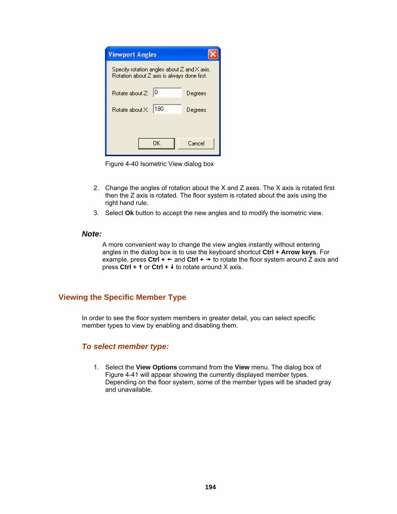
Figure 4-40 Isometric View dialog box
2. Change the angles of rotation about the X and Z axes. The X axis is rotated first
then the Z axis is rotated. The floor system is rotated about the axis using the right hand rule.
3. Select Ok button to accept the new angles and to modify the isometric view.
Note: A more convenient way to change the view angles instantly without entering angles in the dialog box is to use the keyboard shortcut Ctrl + Arrow keys. For example, press Ctrl + and Ctrl + to rotate the floor system around Z axis and press Ctrl + or Ctrl + to rotate around X axis.
Viewing the Specific Member Type In order to see the floor system members in greater detail, you can select specific member types to view by enabling and disabling them.
To select member type:
1. Select the View Options command from the View menu. The dialog box of Figure 4-41 will appear showing the currently displayed member types. Depending on the floor system, some of the member types will be shaded gray and unavailable.
194
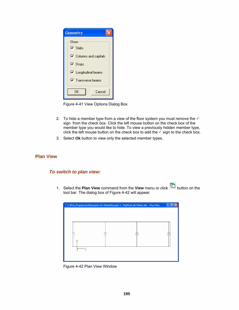
Figure 4-41 View Options Dialog Box
2. To hide a member type from a view of the floor system you must remove the
sign from the check box. Click the left mouse button on the check box of the member type you would like to hide. To view a previously hidden member type, click the left mouse button on the check box to add the sign to the check box.
3. Select Ok button to view only the selected member types.
Plan View
To switch to plan view:
1. Select the Plan View command from the View menu or click button on the tool bar. The dialog box of Figure 4-42 will appear.
Figure 4-42 Plan View Window
195

2. Right click on the view window to show the pop-up menu. You may save the BMP) file or metafile (EMF) on the Windows
ap or Copy Metafile, respectively. You may also select the commands from the pop-up menu to zoom in or zoom out the
current view window as bitmap (clipboard by selecting Copy Bitm
view window and preview it before printing it out.
Figure 4-43 Pop-up Menu of View Window
3. Select the Options command from the pop-up menu, and then you may decide
wn in floor system you must
lick the left mouse button on the check ly hidden he sign to
what geometry members need to be shown on the view window as shoFigure 4-44. To hide a member type from a view of theremove the sign from the check box. Cbox of the member type you would like to hide. To view a previousmember type, click the left mouse button on the check box to add tthe check box.
Figure 4-44 Geometry Options of Plan View
4. Select Ok button to view only the selected member types.
196

Elevated View
iew menu or click
To switch to elevated view:
1. Select the Elevated View command from the V button om the tool bar. The dialog box of Figure 4-45 will appear. fr
Figure 4-45 Elevated View Window
nu. You may save the EMF) onto the Windows , respectively. You may om in or zoom out the
preview it before printing it out.
2. Right click on the view window to show the pop-up me
current view window as bitmap (BMP) file or metafile (clipboard by selecting Copy Bitmap or Copy Metafilealso select the commands from the pop-up menu to zoview window and
Figure 4-46 Pop-up Menu of View Window
then you may decide
dow as shown in a view of the floor system you must
ck
o eck box.
3. Select the Options command from the pop-up menu, andwn on the view winwhat geometry members need to be sho
Figure 4-47. To hide a member type fromremove the sign from the check box. Click the left mouse button on the che
the member type you would like to hide. To view a previously hidden box ofmember type, click the left mouse button on the check box to add the sign tthe ch
197

Figure 4-47 Geometry Options of Elevated View
4. Select Ok button to view only the selected member types.
Side View
To switch to side view:
1. Select the Elevated View command from the View menu or click button from the tool bar. The dialog box of Figure 4-48 will appear.
Figure 4-48 Side View Window
2. Right click on the view window to show the pop-up menu. You may save the
ows ay e
current view window as bitmap (BMP) file or metafile (EMF) onto the Windclipboard by selecting Copy Bitmap or Copy Metafile, respectively. You malso select the commands from the pop-up menu to zoom in or zoom out th
198

view window and preview it before printing it out.
Figure 4-49 Pop-up Menu of View Window
nu, and then you may decide view window as shown in f the floor system you must eft mouse button on the check
usly hidden eck box to add the sign to
3. Select the Options command from the pop-up me
what geometry members need to be shown on theFigure 4-50. To hide a member type from a view oremove the sign from the check box. Click the lbox of the member type you would like to hide. To view a previomember type, click the left mouse button on the chthe check box.
Figure 4-50 Geometry Options of Side View
4. Select Ok button to view only the selected member types.
Iso
or click
metric View
To switch to isometric view:
1. Select the Isometric View command from the View menu button on the tool bar. The dialog box of Figure 4-51 will appear.
199

Figure 4-51 Isometric View Window
2. Right click on the view window to show the pop-up menu. You may save the
) onto the Windows spectively. You may in or zoom out the
current view window as bitmap (BMP) file or metafile (EMFclipboard by selecting Copy Bitmap or Copy Metafile, realso select the commands from the pop-up menu to zoomview window and preview it before printing it out.
Figure 4-52 Pop-up Menu of View Window
3. Select the Options command from the pop-up menu, and then you may decide
indow as shown in or system you must e button on the check
previously hidden type, click the left mouse button on the check box to add the sign to
what geometry members need to be shown on the view wFigure 4-53. To hide a member type from a view of the floremove the sign from the check box. Click the left mousbox of the member type you would like to hide. To view a memberthe check box.
200

Figure 4-53 Geometry Options of Isometric View
Loa
w menu or click
4. Select Ok button to view only the selected member types.
ds
To show the loads:
1. Select the Loads command from the Vie button from the tool bar. The dialog box of Figure 4-54 will appear.
Figure 4-54 Loads View Window
2. Right click on the view window to show the pop-up menu. You may save the
r metafile (EMF) onto the Windows y Metafile, respectively. You may
menu to zoom in or zoom out the t out.
current view window as bitmap (BMP) file oclipboard by selecting Copy Bitmap or Copalso select the commands from the pop-up view window and preview it before printing i
201

Figure 4-55 Pop-up menu of View Window
3. Select the Options command from the pop-up menu, and then you may decide
what kind of loads need to be shown on the view window as shown in Figure 4-56. To hide a load case or type you must remove the sign from the check box. Click the left mouse button on the check box of the member type you would like to hide. To view a previously hidden load type, click the left mouse button on the check box to add the sign to the check box.
Figure 4-56 Loads Options
4. If you want to hide the load values, remove the sign before Show values
check box. 5. Select Ok button to view only the selected member types.
View Results Report
Viewing Results Report Once the analysis and/or design is performed, you can view the results, shear and moment diagrams, and deflected shapes. This section provides procedures performing these functions.
202

To view the analysis and design results:
1. Select Report command from the Solve menu or click the button from the
tool bar. A dialog box similar to Figure 4-57 will appear.
Figure 4-57 View and Print Results Dialog Box
2. Select the results you want to view from the drop-down list. The contents of the
results box will be changed based on your selection. The Customize option allows for more than one result selection to be viewed in the results report.
3. Press the Copy button to copy the current results into the Windows clipboard. Then you may use Ctrl + V to paste the contents of the clipboard to any other editors such
4. Press the Cl
Saving Results Report Analysis and design results are automatically saved to a text file named "projectname.out" in the same folder as the project data file (.slb file). The contents of the .out file depends on which option is selected from the drop-down list on the Results Report dialog box. For example, if the project name is "Example 1 - FlatPlate (ACI Note)" and Input Echo is selected from the Results Report dialog box as shown in Figure 4-58, a text file named "Example 1 - FlatPlate (ACI Note).out" is generated automatically in the same directory as "Example 1 - FlatPlate (ACI Note).slb".
as Word or Notepad. ose button to close the result dialog box.
203

Figure 4-58 Input Echo is selected from Results Report dialog box
The file "Example 1 - FlatPlate (ACI Note).out" is a pure text file and can be opened, edited and printed using Word or Wordpad as shown in Figure 4-59.
Figure 4-59 Output file is opened using Wordpad
Note: Once another option is selected from the Results Report dialog box, the contents of the .out file is changed based on the selection. Output files (.out file) may not be in proper format if opened using Microsoft Notepad. Please use Word or Wordpad.
204

iew Graphical Results
grams
een performed, you may view the shear and moment diagrams for ble loading pattern. The shear and moment window will be split in
alf horizontally. The shear diagram will occupy the upper half and the moment diagram will occupy the lower half where each diagram will be scaled to fill the entire half of the
To view shears and moments diagram:
1. Select the Shears and Moments command from the View menu or click the
V
Viewing the Shear and Moment Dia Once the design has bany span at any availah
window.
button on the tool bar. A view window similar to Figure 4-60 will appear. The upper half view window shows the shear diagram and the lower half the view window shows the moment diagram.
Figure 4-60 View Shear and Moment Diagram
2. The current coordinate values can be captured based on the position of the
mouse curser. The status bar in Figure 4-61 shows the name of the diagram, two coordinate values of the current mouse curser position, and the current design code used in the project.
Figure 4-61 Coordinate Value Shown in Status Bar
3. Click the right mouse button anywhere on the view window to show the pop-up
menu. You may Restore, Zoom, Pan or Print View directly by selecting
205

commands from this pop-up menu. m the pop-up menu to change the span for which
the shear and moment diagram will be shown. Figure 4-62 shows the Options dialog box. Select a span number from the Show diagram for drop-down list and
check list box. Press the OK button to close the dialog box and redraw the view
4. Click the Options command fro
select a load Envelope or combination from the Select load combinations
windows.
Figure 4-62 View Shear and Moment Diagram Options
Note: The pop-up menu can be accessed from each of the view windows of pcaSlab.
or
n command, one can only restores a view using the Restore command
The Restore command cannot be executed in the pop-up menu until the ZoomPan command is stopped by pressing the Esc key. Without stopping the Zoom/Pa
in View menu or button in the tool bar. This occurs on all pcaSlab view
Vie y
u may view the moment capacity diagrams for tern. The moment capacity window will be split in
nt capacity will occupy the upper half and the be
or click the
windows.
wing the Moment Capacit Once the design has been performed, yoany span at any available loading pathalf horizontally. The middle strip momecolumn strip moment capacity will occupy the lower half where each diagram willscaled to fill the entire half of the window.
To view moment capacity:
1. Select the Moment Capacity command from the View menu
206

button on the tool bar. A view window similar to Figure 4-63 will appear.
Figure 4-63 View Moment Capacity Diagram
elect Options command 4 will appear.
2. Right click on the Moment Capacity view window and s
from the pop-up menu. A dialog box similar to Figure 4-6
Figure 4-64 View Moment Capacity Option bialog box
dinate values can be captured based on the position of the e status bar shows the name of the diagram, two coordinate
rent mouse curser position, and the current design code used in
use button anywhere on the view window to show the pop-up may Restore, Zoom, Pan or Print View directly by selecting
hange the span for which elect which span will be shown in the Show
part of the selected span will be shown
Press the OK button to close the dialog box and redraw the view windows.
3. The current coor
mouse curser. Thvalues of the curthe project.
4. Click the right momenu. Youcommands from this pop-up menu.
5. Click the Options command from the pop-up menu to cthe moment capacity will be shown. Sdiagram for drop-down list. Select whichin the Show frame box.
6.
207

Vie Capacity
ab shear capacity diagrams for
1. Select the Shear Capacity command from the View menu or click the
wing the Shear Once the design has been performed, you may view the slany span at any available loading pattern.
To view shear capacity:
button on the tool bar. A view window similar to Figure 4-65 will appear.
Figure 4-65 View Shear Capacity
2. Right click on the Shear Capacity view window and select Options command
from the pop-up menu. A dialog box similar to Figure 4-66 will appear.
Figure 4-66 View Shear Capacity Option dialog box
3. The current coordinate values can be captured based on the position of the
208

mouse curser. The status bar shows the name of the diagram, two coordinate values of the current mouse curser position, and the current design code used in the project.
4. Click the right mouse button anywhere on the view window to show the pop-up menu. You may Restore, Zoom, Pan or Print View directly by selecting commands from this pop-up menu.
5. Click the Options command from the pop-up menu to change the span for which the shear capacity will be shown. Select which span will be shown in the Show diagram for drop-down list. Select which part of the selected span will be shown in the Show frame box.
6. Press the OK button to close the dialog box and redraw the view windows.
Viewing the Reinforcement Once the design has been performed, you may view the reinforcement diagrams for any span at any available loading pattern. The reinforcement window will be split in half horizontally. The middle strip reinforcement will occupy the upper half, and the column strip reinforcement will occupy the lower half where each diagram will be scaled to fill the entire half of the window.
To view reinforcement:
1. Select the Reinforcement command from the View menu or click the button on the tool bar. A view window similar to Figure 4-67 will appear.
Figure 4-67 View Reinforcement
2. Right click on the Reinforcements view window and select Options command
from the pop-up menu. A dialog box similar to Figure 4-68 will appear.
209

Figure 4-68 View Reinforcement Options Dialog Box
3. The current coordinate values can be captured based on the position of the
mouse curser. The status bar shows the name of the diagram, coordinate value of the current mouse curser position in the design direction, and the current design code used in the project.
4. Click the right mouse button anywhere on the view window to show the pop-up menu. You may Restore, Zoom, Pan or Print View directly by selecting commands from this pop-up menu.
5. Click the Options command from the pop-up menu to change the span for which the shear capacity will be shown. Select the span you want to show from the Show diagram for drop-down list. Select which part of the selected span will be shown from the Show frame box. Checking the Show rebar labels will show labels beside each rebar on the view.
6. Press the OK button to close the dialog box and redraw the view windows.
Viewing the Deflected Shapes Once the design has been performed, you may view the deflection shapes for any span at any available loading pattern.
To view the deflection shapes:
1. Select the Deflection command from the View menu or click the button on the tool bar. A view window similar to Figure 4-69 will appear.
210

Figure 4-69 View Deflection Diagram
2. Right click on the Deflection view window and select Options command from
the pop-up menu. A dialog box similar to Figure 4-70 will appear.
Figure 4-70 View Deflection Option dialog box
3. The current coordinate values can be captured based on the position of the
mouse curser. The status bar shows the name of the diagram, two coordinate values of the current mouse curser position, and the current design code used in the project.
4. Click the right mouse button anywhere on the view window to show the pop-up menu. You may Restore, Zoom, Pan or Print View directly by selecting commands from this pop-up menu.
5. Click the Options command from the pop-up menu to change the span for which the deflection will be shown. Select the span you want to show from the Show diagram for drop-down list. Enter the scale factor in the Scale factor edit box. The bigger the scale factor, the more apparent the deflections will be on the diagram.
6. Press the OK button to close the dialog box and redraw the view windows.
211

Print Results
Printing the Analysis and Design Results Once the analysis and/or design is performed, you can print the results. This section provides procedures for performing these functions.
To print the analysis and design results:
1. Select Report command from the Solve menu or click the button from the tool bar. A dialog box similar to Figure 4-71 will appear.
Figure 4-71 View and Print Results dialog box
2. Select the results you want to view from the drop-down list. The contents of the
results list box will be changed based on your selection. 3. Press the Print button on the dialog box to print the results through a printer. The
printer could be a local printer which is connected to your computer directly, or a network printer.
4. Press the Close button to close the result dialog box.
Printing the Current View Window
Once the design has been performed, you may print the diagrams and views for any span at any available loading pattern by selecting the Print View command from the File menu.
To print a displaying window:
212

1. To select the diagram or view you want to print, single click the left mouse button
on the diagram or view window. 2. Select the Print View command from the File menu. A print preview window
similar to Figure 4-72 will be shown.
Figure 4-72 Print Preview of a View Window
3. Press the Zoom In or Zoom Out buttons or simply click the left mouse button on
the preview to magnify or reduce the size of the preview paper. 4. Press the Next Page button if more than one page need to be printed. 5. Press the Print button to print the view. The printer could be a local printer which
is connected to your computer directly, or a network printer. 6. Press the Close button to close the preview window and go back to pcaSlab.
Print Preview
Print Preview
The Print Preview command allows you to preview and print the current view window
213

(floor system geometry in the plan, elevated and isometric views, prints the shear and moment diagrams, and the deflected shapes).
1. To obtain a view window you must first perform the design, then select what you want to view from the View menu. You may have more than one view window opened. The current view window is the one activated and on top of the others on your screen.
2. Selecting this command closes the pcaSlab main window and opens the print preview window as shown in Figure 4-73.
3. On the print preview window, press the Zoom In or Zoom Out buttons or simply click the left mouse button on the preview window to magnify or reduce the size of the preview paper.
4. Press the Next Page button if more than one page needs to be printed. 5. Press the Print button to print the view. The printer could be a local printer which
is connected to your computer directly, or a network printer. 6. Press the Close button to close the preview window and go back to pcaSlab.
Figure 4-73 Print Preview Window
214

Copy Graphs to Clipboard
Copy Bitmap (BMP format)
One of the nice things about the Windows operating system is that it supplies a standard bitmapped image file format, the BMP. As its name implies, the Windows bitmap format is a direct bitmap representation of an image. pcaSlab can copy any of the ten view windows onto Windows clipboard as bitmap. The bitmap on clipboard can then be pasted into Microsoft Word file or other Windows word processing software, as well as presentation software such as Microsoft PowerPoint.
To copy view window to clipboard as bitmap:
1. Select the view window that will be copied by single clicking left mouse button on it.
2. Select from the tool bar to copy the selected view window to clipboard.
3. Switch to other word processing software, such as Microsoft Word, then press the Ctrl + V to paste the bitmap on clipboard to a Word file.
Copy Metafile (EMF format)
Since bitmap files cannot easily be resized or re-proportioned without significant distortion to the image, metafiles are generally used for situations requiring scalability of the image.
Advantages of metafiles are:
1. Large, simply structured images require less memory than bitmaps for display and make optimal use of the resolution of the output device.
2. Metafiles can be resized with none of the distortion which normally accompanies resizing of bitmaps.
3. A metafile can contain SelectPalette statements, allowing custom palettes to be displayed in applications such as Microsoft Word. (According to Microsoft, this may result in lost resources in 16 bit Windows operating systems.).
215
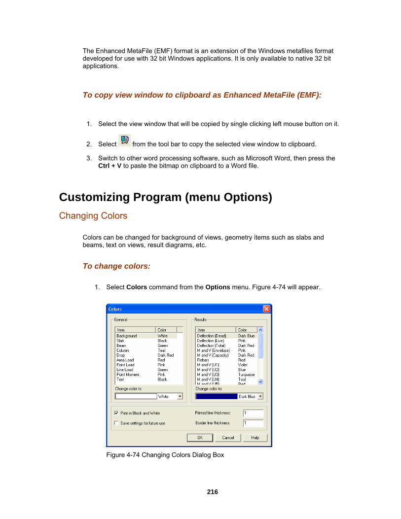
The Enhanced MetaFile (EMF) format is an extension of the Windows metafiles format developed for use with 32 bit Windows applications. It is only available to native 32 bit applications.
To copy view window to clipboard as Enhanced MetaFile (EMF):
1. Select the view window that will be copied by single clicking left mouse button on it.
2. Select from the tool bar to copy the selected view window to clipboard.
3. Switch to other word processing software, such as Microsoft Word, then press the Ctrl + V to paste the bitmap on clipboard to a Word file.
Customizing Program (menu Options) Changing Colors
Colors can be changed for background of views, geometry items such as slabs and beams, text on views, result diagrams, etc.
To change colors:
1. Select Colors command from the Options menu. Figure 4-74 will appear.
Figure 4-74 Changing Colors Dialog Box
216

2. From the General frame box on the left side, select the item whose color needs
to be changed from the list box. 3. Select a color from the Change color to drop-down list. Once a new color is
r in the list box above the drop-down list
4. From the Results category box on the right side, select the item whose color needs to be changed from the list box.
5. Select a color from the Change color to drop-down list. Once a new color is selected from the drop-down list the color in the list box above the drop-down list is updated instantly.
6. If you want to print views in black and white, select the Print Black and White k box.
7. If you want to save the settings as default, select the Save setting for future use check box.
8. Input the line thickness in the Printed Line Thickness edit box. The diagram line thickness will be based on the number you input.
9. Press the OK button to save the settings and close the dialog box.
To change the startup defaults:
1. Select the Startup Defaults command from the Options menu. A view window similar to Figure 4-75 will appear.
selected from the drop-down list the colois updated instantly.
Changing Startup Defaults
chec
Figure 4-75 Changing Startup Defaults Dialog Box
2. Input the name of the engineer in the Engineer edit box. The name of the
engineer will be shown on the view print. 3. Select the design code from the Design code drop-down list. Four design codes
are available: ACI 318-99, ACI 318M-99, CSA A23.3-94 and CSA A23.3-94E. 4. Select the rebar database from the Rebar database drop-down list. Four defined
217
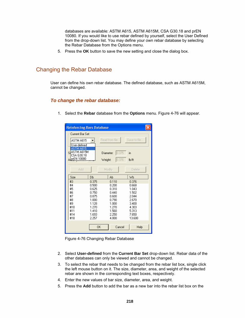
databases are available: ASTM A615, ASTM A615M, CSA G30.18 and prEN 10080. If you would like to use rebar defined by yourself, select the User Defined from the drop-down list. You may define your own rebar database by selecting
ing and close the dialog box.
Changing the Rebar Database User can define his own rebar database. The defined database, such as ASTM A615M, cannot be changed.
To change the rebar database:
1. Select the Rebar database from the Options menu. Figure 4-76 will appear.
the Rebar Database from the Options menu. 5. Press the OK button to save the new sett
Figure 4-76 Changing Rebar Database
2. Select User-defined from the Current Bar Set drop-down list. Rebar data of the
other databases can only be viewed and cannot be changed. 3. To select the rebar that needs to be changed from the rebar list box, single click
the left mouse button on it. The size, diameter, area, and weight of the selected rebar are shown in the corresponding text boxes, respectively.
4. Enter the new values of bar size, diameter, area, and weight. 5. Press the Add button to add the bar as a new bar into the rebar list box on the
218

lower part of the dialog box. If any data inconsistency is found by pcaSlab, an hown.
6. Press the Modify button to update an existing rebar. 7. To delete a rebar, select the rebar from the rebar list box then click the Delete
button. 8. After finishing the definitions of your own rebar database, you may save them
into a file on the hard drive by pressing the Save to file button and specifying a file name for your database. This file can be imported into pcaSlab by pressing the Read from file button.
Working with View Windows (menu Window) Cascade
windows in the same size, arranging them on top of each other so that the title bar of each is visible. The current active view widow will be on the top after the execution of the Cascade command.
Tile Horizontal
The Tile Horizontal command arranges all open windows horizontally so that no window overlaps another. The current active view widow will be on the most left or on the upper-left corner of the screen after the execution of the Tile Horizontal command.
Tile Vertical
The Tile Vertical command arranges all open windows vertically so that no window overlaps another. The current active view widow will be on the most left or on the upper-left corner of the screen after the execution of the Tile Vertical command.
Remaining Commands
The remaining menu items are in a list of the windows that are available for viewing. Selecting any window from this menu will restore the window to its previous size and position from an icon.
error of "Inconsistent bar data" will be s
The Cascade command displays all the open
219

Obtaining Help Information (menu Help)
To open Help in Contents mode:
1. Select Contents from the Help menu.
2. Select the chapter you need from the content tree view in the left pane of the Help window. The contents of the selected chapter appear in the right pane of the Help window.
Opening Help in Index Mode
To open Help in Index mode:
1. Select Index from the Help menu.
2. Enter the key word you want to find into the "Type in the Keyword to Find" text box. The most close chapter will be highlighted in the left list box on the Help Window. Double left click the selected chapter to show the contents in the right pane.
Obtaining the Program Version The About box contains the copyright information, the version number of the pcaSlab program, your firm name, city, and state.
To obtain the program version:
1. Select the About pcaSlab command from the Help menu. The dialog box of Figure 4-77 will appear.
Opening Help in Contents mode
220

Figure 4-77 About pcaSlab dialog box
2. Press Ok button to exit the dialog box.
221

Ch. 5 Output Description Output Elements
pcaSlab generates the text and graphical output of the input data and the results of the calculations. The text output is generated when user opens the Results Report dialog window. An ASCII text file is generated in the same sub-folder as the input data file. The name of the output file is created by adding the extension ".OUT" to the name of the input data file. Depending on the report options selected, the text output will contain a selection of the following sections (see the illustrated examples in the following chapter):
• Program Version • [1] Input Echo • [2] Design Results • [3] Column Axial Forces And Moments • [4] Segmental Moment And Shear - Load Cases • [5] Segmental Moment And Shear - Load Combinations • [6] Segmental Moment And Shear – Envelopes • [7] Segmental Deflections
Program Version
The program version number appears at the top of each report page along with the copyright and disclaimer information.
Input Echo
Section Input Echo reports the data used in the analysis. pcaSlab defaults common data; all other data must be input. Carefully check the contents of the section and compare it with the intended design model. The following paragraphs describe the blocks included in the section.
General Information
This block is similar in its content to the dialog window General Information. It contains the information on project input data file name, project description, selected design code and units, selected rebar database, calculation mode (design or investigation), number of supports, cantilevers. The selections available in dialog window Solve Options are also listed in this block.
222

Material Properties
This block contains the information on concrete properties for slabs, beams and columns. It also contains the information on reinforcing steel properties for slabs and beams.
Rebar Database
This block lists the properties of the bars from the bar table selected for the project. Bar diameter, cross-section area and unit weight for each bar are reported. The values reported are consistent with the units used in particular model.
Span Data
This block is similar in its content to the dialog window Span Data. The block is divided into two parts. First part reports the span-by-span geometry of the concrete slab (length, left and right side width, depth and code required minimum thickness). The second part contains the span-by-span geometry of longitudinal beams and ribs (for waffle slabs).
Support Data
This block is similar in its content to the dialog window Support Data. The block is divided into four parts. The first part reports the geometry of top and bottom columns and the stiffness share factor. For circular column the transverse dimension C2 is reported as zero. The second part contains the geometry of drop panels: thickness, lengths, widths. If dimensions of a drop panel are invalid it will be marked. Invalid or excessive drop panel geometry is not used in the analysis. The third part contains the geometry of column capitals: depth, slope (depth/extension ratio), extensions. The fourth part contains the geometry of transverse beams: width depth, eccentricity (offset) from column centroid.
Load Data
This block contains the complete information on load input. The block is divided into three parts. The first part reports the defined load cases, load combinations and corresponding load factors. This part summarizes the contents of the dialog windows Load Cases and Load Combinations. The second part reports the magnitudes of defined span loads. It summarizes the contents of the dialog window Span Loads. The third part reports the magnitudes of lateral actions (joint moments) if defined in the model. It summarizes the contents of the dialog window Lateral Load Effects.
Reinforcement Criteria
This block is similar in its content to the dialog window Reinforcement Criteria. The block is divided into three parts. The first part reports the requirements for slab and rib bars. The second part reports the requirements for longitudinal beams. Both parts contain the information on bar sizes, covers, spacings and user selected allowable steel percentages. The requirements for top and bottom bars are given. For longitudinal beams additionally the criteria for transverse bars (stirrups) are listed.
223

Reinforcing Bars
This block is available only when Investigation Mode is selected. This block is similar in its content to the dialog window Reinforcing Bars. The block is divided into three parts. The first part reports the span-by span user selected top bars for column, middle and beam strips accordingly. Similarly, the second part reports the user selected bottom bars for column, middle and beam. For longitudinal bars the program reports bar sizes, lengths and concrete cover. The third part presents the beam transverse reinforcement (stirrups) defined by the user.
Note:
When switching from Design Mode to Investigation Mode, pcaSlab automatically assumes the results of the Design Mode as an input for Investigation Mode.
Design Results
Section Design Results presents the summary of the design results of the slab system. The following paragraphs describe the blocks included in the section.
Top Reinforcement
This block is available only when Design Mode is selected. It reports the negative reinforcement requirements. The block contains the values of corresponding design strip widths (column, middle, and beam), maximum factored design moments per strip and critical location, minimum and maximum steel areas, bar spacings, steel areas required by ultimate condition, selected bar sizes and numbers. The quantities are given for left, center and right location of each span. For a detailed discussion, see Chapter 2, "Area of Reinforcement".
Note: This block does not include reinforcement quantities necessary to transfer negative unbalanced moment at supports.
Top Bar Details
The block contains a span-by-span listing of the longitudinal bars selected in column, middle and beam strips. This reinforcement schedule is intended as a guide for bar placement. In more complex cases the bar schedule selected by the program may have to be adjusted by the user for constructability reasons. The selected bar sizes are limited by user specified minimum and maximum sizes. Bar sizes and numbers are selected to satisfy the minimum and required steel areas in conjunction with the bar spacing requirements of the Code. The program calculates the bar lengths based on the computed inflection points and the recommended minimums of the Code. The bar lengths are adjusted by appropriate development lengths. Hooks and bends are not
224

included in bar length tables and figures. For beams bars are placed in single a layer (see Figure 2-21), provided there is sufficient beam width. For a detailed discussion, see Chapter 4, "Reinforcement Selection".
Note: This block does not include reinforcement bars necessary to transfer negative unbalanced moment at supports.
Bottom Reinforcement
This block is available only when Design Mode is selected. It reports the positive reinforcement requirements. The block contains the values of corresponding design strip widths (column, middle, and beam), maximum factored design moments per strip and critical location, minimum and maximum steel areas, bar spacings, steel areas required by ultimate condition, selected bar sizes and numbers. The quantities are given for mid-span regions of each span. For a detailed discussion, see Chapter 2, "Area of Reinforcement".
Bottom Bar Details
This block contains a span-by-span listing of the longitudinal bars selected in column, middle and beam strips. The reinforcement schedule is intended as a guide for bar placement. In more complex cases the bar schedule selected by the program may have to be adjusted by the user for constructability reasons. The selected bar sizes are limited by user specified minimum and maximum sizes. Bar sizes and numbers are selected to satisfy the minimum and required steel areas in conjunction with the bar spacing requirements of the Code. The program calculates the bar lengths based on the computed inflection points and the recommended minimums of the Code. The bar lengths are adjusted by appropriate development lengths. Hooks and bends are not included in bar length tables and figures. For beams bars are placed in single a layer (see Figure 2-21), provided there is sufficient beam width. For a detailed discussion, see Chapter 2, "Reinforcement Selection".
Flexural Capacity
This block lists the selected top and bottom steel areas and corresponding negative and positive moment capacity values in each span. The data is subdivided between column, middle and beam strips. Each span is subdivided into segments reflecting the changes in geometry and bar placement.
Longitudinal Beam Shear Reinforcement Required
This block is available only when Design Mode is selected. It reports the requirements of transverse reinforcement for each longitudinal beam. The capacity of concrete cross-section φVc in each span is shown. The table contains the segmental values of the factored shear force Vu and required intensity of stirrups (Av/s). The segmental values cover the distance between left and right critical sections, and include locations where there is change of geometry of loading.
225

226
Longitudinal Beam Shear Reinforcement Details
This block is available only when Design Mode is selected. It is intended as a guide for stirrup placement. The output presents the program selected stirrup sizes, numbers and spacings. Distances between groups of stirrups are also reported.
Beam Shear Capacity
This block lists the concrete section shear capacity φVc, selected stirrup intensities and spacings and corresponding beam shear capacity φVn values in each span. The maximum factored shear forces VBmaxB in beam strip along the span also reported.
Slab Shear Capacity
This block lists the values of one-way slab shear capacity φVc in each span. The maximum factored shear force Vu and the location of the critical section XBu B are also reported.
Flexural Transfer of Negative Unbalanced Moment at Supports
This block reports the design values for negative reinforcement necessary to transfer unbalanced support moments. The block contains the results for critical (effective) section width as per the Code, the maximum unbalanced moment, the corresponding load combination and governing load pattern, the reinforcing steel areas provided and additional steel required. The provided reinforcement area (main longitudinal bars) is reduced by the ratio of critical (effective) strip width to total strip width and does not include the required area due to unbalanced moments. The additional reinforcement is the difference between that required by unbalanced moment transfer by flexure and that provided for design bending moment. When additional reinforcement is required, it is selected based on the bar sizes already provided at the support. For a detailed discussion, see Chapter 2, "Area of Reinforcement" and "Additional Reinforcement at Support".
Punching Shear Around Columns
The block contains the values pertaining to punching shear check in critical sections around the columns. The table lists two sets of punching shear calculations – direct shear alone and direct shear with moment transfer. The output contains the values of the allowable shear stress φvBc B, reactions Vu, unbalanced moments MBunb B, governing load pattern, fraction of unbalanced moment �v, punching shear stress vu. The calculation for moment transfer adjusts the unbalanced moment to the centroid of the critical section. The "shear transfer" is the unbalanced moment multiplied by φv. When calculated shear stress vu exceeds the allowable value φvBc B, the program prints a warning flags for this support. For a detailed discussion, see Chapter 2, "Shear Analysis of Slabs".
Punching Shear Around Drops

227
The block contains the values pertaining to punching shear check in a critical section around the drop panels. The table displays the reactions VBu B, governing load pattern, the punching shear stress around the drop v Bu B, and the allowable shear stress φvc. When calculated shear stress vBu B exceeds the allowable value φvc, the program prints a warning flags for this drop panel. For a detailed discussion, see Chapter 2, "Shear Analysis of Slabs".
Maximum Deflections
This block lists the summary of dead load (DL), live load (LL) and total (DL+LL) short-time deflections for the entire equivalent frame, column and middle strips. If solution option "Gross (uncracked) sections" is selected, the values of deflections reported are based on gross section properties. If solution option "Effective (cracked) sections" is used, the values of deflections reported are based on substitute effective moment of inertia of the section. For a detailed discussion, see Chapter 2, "Deflection Calculation".
Material Takeoff
This block lists the approximate total and unit quantities of concrete, and reinforcement. Note that the reinforcement estimate is for one direction only and ignores items such as hooks, bends, and waste. For a detailed discussion, see Chapter 2, "Material Quantities".
Column Axial Forces And Moments
Section Column Axial Forces And Moments presents the summary of unfactored axial forces (reactions) and bending moments in bottom and top columns in the column-slab joints. The values reported represent the loading of a single floor only. Any actions on the columns from the floors above must be added to this story’s actions to properly analyze/design the columns. The output contains column actions due to Selfweight, Dead Load, Live Load, and Total Combination. The Live Load values for all four load patterns are presented. The values for Live Load pattern No.4 are not combined because this load pattern is not singular (each support has is individual load configuration).
Segmental Moment And Shear - Load Cases
This section presents the summary of unfactored bending moments and shear forces for individual load cases including selfweight, dead load, live load and lateral cases. The reported values are presented using span-by-span segmental approach.

228
Segmental Moment And Shear - Load Combinations
This section presents the summary of bending moments and shear forces for each load combination. The reported values for each load combination are presented using span-by-span segmental approach. The negative and positive values of bending moments and shear forces are presented in separate columns in order to provide consistent format with enveloped output.
Segmental Moment And Shear - Envelopes
This section presents the summary of bending moments and shear forces for envelope of all load combinations. The reported values are presented using span-by-span segmental approach. The negative and positive values of bending moments and shear forces are presented in separate columns for user convenience. The factored values presented in this section are used for design purposes (longitudinal and transverse reinforcement).
Segmental Deflections
This section presents the summary of deflections for unfactored (service) load cases including selfweight and dead load (DL), live load (LL) and combined (DL+LL) load cases. The reported values are presented using span-by-span segmental approach. If solution option "Gross (uncracked) sections" is selected, the values of deflections reported are based on gross section properties. If solution option "Effective (cracked) sections" is used, the values of deflections reported are based on substitute effective moment of inertia of the section. For a detailed discussion, see Chapter 2, "Deflection Calculation".
Graphical Output
pcaSlab provides the following graphical output features:
Shear and Moment Diagrams Moment Capacity Diagram Shear Capacity Diagram Deflection Diagram Reinforcement Diagram

229
These diagram windows can be customized. The options dialog allows selecting either a single span or all spans. Other elements of the graphs can also be modified. pcaSlab print preview of the current graphical window. The user has also the choice to export the graphics to a metafile or bitmap file.
Detailed information on using the graphical output features is included in chapter "Operating the Program".

230
Ch. 6 Examples Flat Slab Problem Description
Analyze and design an interior strip shown in Figure 6-1.
Figure 6-1 Example flat slab problem

231
Calculation Results - Text Output
The following listing contains the first three sections of the result report for Example 1.
ooooooo oooooo ooooo oooooooo oooooooo ooooooo oo oo oo oo oo oo oo oo oo oo oo oooooooo oo ooooooo ooooo ooooooo oo oo ooooooo ooooo oo oo oo oo oo oo oooooooo oo oo oo oooooo oo oo oooooo o o oooooooo oo ooooo oo oo oo o oo oo oooo oo o oo oo oooooo oo oooooo oooooo oooo oo oo oo oo oo oo oo oo oo oo oo oooooooo oo o oo oo oo oo oooooo ooo ooooo o ooooo ============================================================================= pcaSlab V1.01 (TM) A Computer Program for Analysis and Design of Slab Systems ============================================================================= Copyright © 2000-2003, Portland Cement Association All rights reserved Licensee stated above acknowledges that Portland Cement Association (PCA) is not and cannot be responsible for either the accuracy or adequacy of the material supplied as input for processing by the pcaSlab computer program. Furthermore, PCA neither makes any warranty expressed nor implied with respect to the correctness of the output prepared by the pcaSlab program. Although PCA has endeavored to produce pcaSlab error free the program is not and cannot be certified infallible. The final and only responsibility for analysis, design and engineering documents is the licensees. Accordingly, PCA disclaims all responsibility in contract, negligence or other tort for any analysis, design or engineering documents prepared in connection with the use of the pcaSlab program. ============================================================================================= [1] INPUT ECHO ============================================================================================= General Information: ==================== File name: C:\Program Files\PCA\pcaslab\Examples Adoss\fltslb.slb Project: FLAT SLAB -INTERIOR BENT-VERTICAL Frame: Adoss Example 2 Engineer: PCA Code: ACI 318-99 Mode: Design Rebar Database: ASTM A615 Number of supports = 6 + Left cantilever + Right cantilever Live load pattern ratio = 100% Minimum free edge for punching shear = 10 times slab thickness Deflections are based on cracked section properties. Material Properties: ==================== Slabs|Beams Columns ------------ ------------ wc = 150 150 lb/ft3 f'c = 4 4 ksi Ec = 3834.25 3834.25 ksi fr = 0.4743 0.4743 ksi fy = 60 ksi, Bars are not epoxy-coated fyv = 60 ksi Es = 29000 ksi Rebar Database: =============== Units: Db (in), Ab (in^2), Wb (lb/ft) Size Db Ab Wb Size Db Ab Wb ---- -------- -------- -------- ---- -------- -------- -------- #3 0.38 0.11 0.38 #4 0.50 0.20 0.67 #5 0.63 0.31 1.04 #6 0.75 0.44 1.50 #7 0.88 0.60 2.04 #8 1.00 0.79 2.67 #9 1.13 1.00 3.40 #10 1.27 1.27 4.30 #11 1.41 1.56 5.31 #14 1.69 2.25 7.65

232
#18 2.26 4.00 13.60 Span Data: ========== Slabs: L1, wL, wR (ft); t (in) Span Loc L1 t wL wR Hmin ---- ---- -------- -------- -------- -------- -------- 1 Int 0.670 8.00 9.000 9.000 7.20 LC 2 Int 18.300 8.00 9.000 9.000 6.22 3 Int 18.300 8.00 9.000 9.000 5.71 4 Int 18.300 8.00 9.000 9.000 6.22 5 Int 18.300 8.00 8.000 8.000 6.22 6 Int 12.500 8.00 8.000 8.000 5.39 7 Int 6.000 8.00 8.000 8.000 6.40 RC Support Data: ============= Columns: c1a, c2a, c1b, c2b (in); Ha, Hb (ft) Supp c1a c2a Ha c1b c2b Hb Red% ---- -------- -------- -------- -------- -------- -------- ---- 1 0.00 0.00 0.000 16.00 0.00 10.000 100 2 0.00 0.00 0.000 16.00 0.00 10.000 100 3 0.00 0.00 0.000 16.00 0.00 10.000 100 4 0.00 0.00 0.000 16.00 0.00 10.000 100 5 0.00 0.00 0.000 16.00 0.00 10.000 100 6 0.00 0.00 0.000 16.00 0.00 10.000 100 Drop Panels: h (in); L1, L2, W1, W2 (ft) Supp h L1 L2 W1 W2 ---- -------- -------- -------- -------- -------- 1 3.00 0.670 3.050 3.000 3.000 *d 2 3.00 3.050 3.050 3.000 3.000 3 3.00 3.050 3.050 3.000 3.000 4 3.00 3.050 3.050 2.667 2.667 *c d 5 3.00 3.050 2.083 2.667 2.667 6 3.00 2.083 6.000 2.667 2.667 *c- Invalid drop. Drop thickness will not be used for flexural design. *d- Excessive drop thickness will not be used for flexural design. Load Data: ========== Load Cases and Combinations: Case SELF Dead Live Type DEAD DEAD LIVE U1 1.400 1.400 1.700 Span Loads: Span Case Wa La Wb Lb ---- -------- ------------ ------------ ------------ ------------ Line Loads - Wa | Wb (lb/ft), La | Lb (ft): 7 Dead 500 5.5 500 6 6 Live 800 2.5 800 10 7 Live 50 5.5 50 6 Area Loads - Wa (lb/ft2): 2 Dead 10 3 Dead 10 4 Dead 10 5 Dead 10 6 Dead 10 7 Dead 10 2 Live 50 3 Live 50 4 Live 50 5 Live 50 6 Live 100 7 Live 40 Reinforcement Criteria: ======================= _____Top bars___ ___Bottom bars__ ____Stirrups____ Min Max Min Max Min Max ------- ------- ------- ------- ------- ------- Slabs and Ribs: Bar Size #4 #8 #4 #8 Bar spacing 6.00 18.00 6.00 18.00 in Reinf ratio 0.18 2.00 0.18 2.00 % Cover 1.50 1.00 in Beams: Bar Size #5 #8 #5 #8 #3 #5 Bar spacing 2.00 18.00 2.00 18.00 6.00 18.00 in Reinf ratio 0.20 2.00 0.20 2.00 % Cover 1.50 1.50 in ============================================================================================= [2] DESIGN RESULTS ============================================================================================= Top Reinforcement: ================== Units: Width (ft), Mmax (k-ft), Xmax (ft), As (in^2), Sp (in)

233
Span Strip Zone Width Mmax Xmax AsMin AsMax SpReq AsReq Bars ---- ------ ------ -------- ------------ -------- -------- -------- -------- -------- ------- 1 Column Left 9.00 0.00 0.001 1.555 13.500 13.500 0.000 8-#4 Middle 9.00 0.00 0.002 1.555 14.013 0.000 0.000 8-#4 Right 9.00 0.00 0.003 1.586 9.342 10.800 0.000 10-#4 Middle Left 9.00 0.00 0.001 1.555 13.500 13.500 0.000 8-#4 Middle 9.00 0.00 0.002 1.555 13.500 13.500 0.000 8-#4 Right 9.00 0.00 0.003 1.555 13.500 13.500 0.000 8-#4 2 Column Left 9.00 29.69 0.667 1.944 13.320 10.800 0.720 10-#4 Middle 9.00 0.00 0.000 0.000 0.000 0.000 0.000 --- Right 9.00 103.72 17.633 1.944 13.320 8.308 2.580 13-#4 Middle Left 9.00 -0.00 0.667 1.555 13.500 13.500 0.000 8-#4 Middle 9.00 0.00 0.000 0.000 0.000 0.000 0.000 --- Right 9.00 34.58 17.633 1.555 13.500 13.500 1.250 8-#4 3 Column Left 9.00 99.00 0.667 1.944 13.320 8.308 2.458 13-#4 Middle 9.00 0.43 6.605 1.555 13.500 0.000 0.015 8-#4 Right 9.00 84.43 17.633 1.944 13.320 9.818 2.086 11-#4 Middle Left 9.00 33.00 0.667 1.555 13.500 13.500 1.192 8-#4 Middle 9.00 0.14 6.605 1.555 13.500 0.000 0.005 8-#4 Right 9.00 28.14 17.633 1.555 13.500 13.500 1.014 8-#4 4 Column Left 9.00 85.40 0.667 1.944 13.320 9.818 2.111 11-#4 Middle 9.00 0.00 0.000 0.000 0.000 0.000 0.000 --- Right 8.00 85.58 17.633 1.382 11.880 8.727 3.228 11-#5 Middle Left 9.00 28.47 0.667 1.555 13.500 13.500 1.026 8-#4 Middle 9.00 0.00 0.000 0.000 0.000 0.000 0.000 --- Right 10.00 28.53 17.633 1.728 15.000 13.333 1.027 9-#4 5 Column Left 8.00 85.74 0.667 1.382 11.880 8.727 3.235 11-#5 Middle 8.00 0.00 0.000 0.000 0.000 0.000 0.000 --- Right 6.25 71.16 17.633 1.426 11.840 8.333 1.755 9-#4 Middle Left 8.00 28.58 0.667 1.382 12.000 13.333 1.032 9-#4 Middle 8.00 0.00 0.000 0.000 0.000 0.000 0.000 --- Right 9.75 23.72 17.633 1.685 14.625 13.000 0.852 9-#4 6 Column Left 6.25 65.37 0.667 1.426 11.840 8.333 1.609 9-#4 Middle 6.25 14.23 4.575 1.080 9.375 0.000 0.511 6-#4 Right 6.25 54.69 11.833 1.426 11.840 9.375 1.341 8-#4 Middle Left 9.75 21.79 0.667 1.685 14.625 13.000 0.782 9-#4 Middle 9.75 2.76 4.575 1.685 14.625 0.000 0.098 9-#4 Right 9.75 -0.00 11.833 1.685 14.625 13.000 0.000 9-#4 7 Column Left 6.25 56.52 0.667 1.426 11.840 9.375 1.386 8-#4 Middle 6.25 24.30 2.533 1.080 13.875 9.375 0.588 8-#4 Right 6.25 7.34 4.133 1.080 9.375 9.375 0.262 8-#4 Middle Left 9.75 0.00 0.667 1.685 14.625 13.000 0.000 9-#4 Middle 9.75 0.00 2.533 1.685 14.625 13.000 0.000 9-#4 Right 9.75 0.00 4.133 1.685 14.625 13.000 0.000 9-#4 Top Bar Details: ================ Units: Length (ft) _____________Left______________ ___Continuous__ _____________Right_____________ Span Strip Bars Length Bars Length Bars Length Bars Length Bars Length ---- ------ ------- ------- ------- ------- ------- ------- ------- ------- ------- ------- 1 Column --- --- 8-#4 0.67 2-#4 0.67 --- Middle --- --- 8-#4 0.67 --- --- 2 Column 5-#4 6.27 5-#4 4.06 --- 7-#4 6.60 6-#4 4.06 Middle 8-#4 4.40 --- --- 8-#4 6.60 --- 3 Column 5-#4 6.27 --- 8-#4 18.30 3-#4 6.27 --- Middle --- --- 8-#4 18.30 --- --- 4 Column 6-#4 6.60 5-#4 4.06 --- 6-#5 6.60 5-#5 4.06 Middle 8-#4 6.60 --- --- 9-#4 6.60 --- 5 Column 6-#5 7.10 5-#5 4.06 --- 5-#4 6.27 4-#4 4.06 Middle 9-#4 7.10 --- --- 9-#4 6.10 --- 6 Column 3-#4 4.35 --- 6-#4 12.50 2-#4 4.35 --- Middle --- --- 9-#4 12.50 --- --- 7 Column --- --- 8-#4 6.00 --- --- Middle --- --- 9-#4 6.00 --- --- Bottom Reinforcement: ===================== Units: Width (ft), Mmax (k-ft), Xmax (ft), As (in^2), Sp (in) Span Strip Width Mmax Xmax AsMin AsMax SpReq AsReq Bars ---- ------ -------- ------------ -------- -------- -------- -------- -------- ------- 1 Column 9.00 0.00 0.000 0.000 14.580 0.000 0.000 --- Middle 9.00 0.00 0.000 0.000 14.580 0.000 0.000 ---

234
2 Column 9.00 52.46 8.030 1.555 14.580 12.000 1.765 9-#4 Middle 9.00 34.97 8.030 1.555 14.580 13.500 1.168 8-#4 3 Column 9.00 35.21 9.523 1.555 14.580 13.500 1.176 8-#4 Middle 9.00 23.47 9.523 1.555 14.580 13.500 0.780 8-#4 4 Column 9.00 39.78 9.026 1.555 14.580 13.500 1.331 8-#4 Middle 9.00 26.52 9.026 1.555 14.580 13.500 0.882 8-#4 5 Column 8.00 35.46 9.523 1.382 12.960 13.714 1.187 7-#4 Middle 8.00 23.64 9.523 1.382 12.960 13.714 0.787 7-#4 6 Column 6.25 29.22 6.495 1.080 10.125 12.500 0.979 6-#4 Middle 9.75 19.48 6.495 1.685 15.795 13.000 0.646 9-#4 7 Column 6.25 0.00 0.000 0.000 10.125 0.000 0.000 --- Middle 9.75 0.00 0.000 0.000 15.795 0.000 0.000 --- Bottom Bar Details: =================== Units: Start (ft), Length (ft) _______Long Bars_______ ______Short Bars_______ Span Strip Bars Start Length Bars Start Length ---- ------- ------- ------- ------- ------- ------- ------- 1 Column --- --- Middle --- --- 2 Column 9-#4 0.00 18.30 --- Middle 4-#4 0.00 18.30 4-#4 0.00 15.56 3 Column 8-#4 0.00 18.30 --- Middle 4-#4 0.00 18.30 4-#4 2.75 12.81 4 Column 8-#4 0.00 18.30 --- Middle 4-#4 0.00 18.30 4-#4 2.75 12.81 5 Column 7-#4 0.00 18.30 --- Middle 4-#4 0.00 18.30 3-#4 2.75 12.81 6 Column 6-#4 0.00 12.50 --- Middle 5-#4 0.00 12.50 4-#4 1.88 10.63 7 Column --- --- Middle --- --- Flexural Capacity: ================== Units: From, To (ft), As (in^2), PhiMn (k-ft) Span Strip From To AsTop AsBot PhiMn- PhiMn+ ---- ------ --------- --------- ----- ----- ------------ ------------ 1 Column 0.000 0.001 2.00 0.00 -54.78 0.00 0.001 0.002 2.00 0.00 -56.92 0.00 0.002 0.003 2.00 0.00 -56.18 0.00 0.003 0.670 2.00 0.00 -56.18 0.00 Middle 0.000 0.001 1.60 0.00 -44.06 0.00 0.001 0.002 1.60 0.00 -44.06 0.00 0.002 0.003 1.60 0.00 -44.06 0.00 0.003 0.670 1.60 0.00 -44.06 0.00 2 Column 0.000 0.667 2.00 1.80 -81.04 53.48 0.667 3.050 2.00 1.80 -81.04 53.48 3.050 4.061 2.00 1.80 -54.78 53.48 4.061 6.266 1.00 1.80 -27.76 53.48 6.266 6.605 0.00 1.80 0.00 53.48 6.605 11.695 0.00 1.80 0.00 53.48 11.695 11.700 0.00 1.80 0.00 53.48 11.700 14.239 1.40 1.80 -38.65 53.48 14.239 15.250 2.60 1.80 -70.64 53.48 15.250 17.633 2.60 1.80 -104.50 53.48 17.633 18.300 2.60 1.80 -104.50 53.48 Middle 0.000 0.667 1.60 1.60 -44.06 47.66 0.667 4.400 1.60 1.60 -44.06 47.66 4.400 6.605 0.00 1.60 0.00 47.66 6.605 11.695 0.00 1.60 0.00 47.66 11.695 11.700 0.00 1.60 0.00 47.66 11.700 15.555 1.60 1.60 -44.06 47.66 15.555 17.633 1.60 0.80 -44.06 24.06 17.633 18.300 1.60 0.80 -44.06 24.06 3 Column 0.000 0.667 2.60 1.60 -104.50 47.66 0.667 3.050 2.60 1.60 -104.50 47.66 3.050 6.266 2.60 1.60 -70.64 47.66 6.266 6.605 1.60 1.60 -44.06 47.66 6.605 11.695 1.60 1.60 -44.06 47.66 11.695 12.034 1.60 1.60 -44.06 47.66 12.034 15.250 2.20 1.60 -60.10 47.66 15.250 17.633 2.20 1.60 -88.91 47.66 17.633 18.300 2.20 1.60 -88.91 47.66 Middle 0.000 0.667 1.60 0.80 -44.06 24.06 0.667 2.745 1.60 0.80 -44.06 24.06 2.745 6.605 1.60 1.60 -44.06 47.66
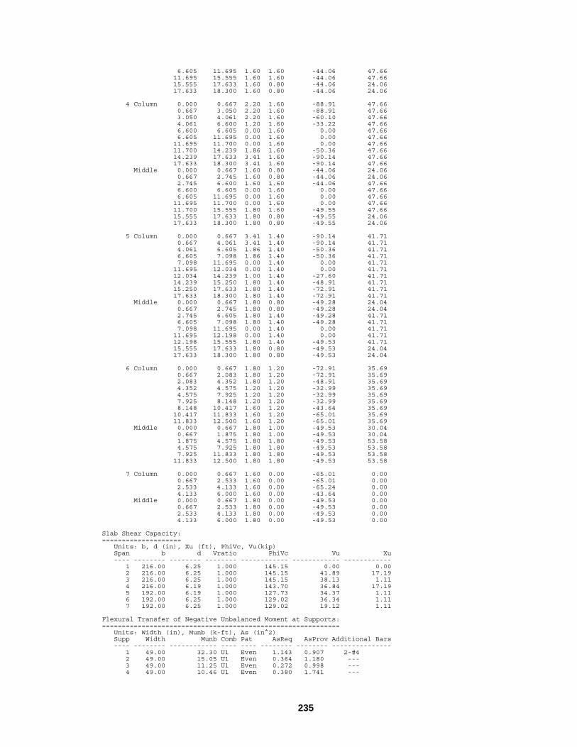
235
6.605 11.695 1.60 1.60 -44.06 47.66 11.695 15.555 1.60 1.60 -44.06 47.66 15.555 17.633 1.60 0.80 -44.06 24.06 17.633 18.300 1.60 0.80 -44.06 24.06 4 Column 0.000 0.667 2.20 1.60 -88.91 47.66 0.667 3.050 2.20 1.60 -88.91 47.66 3.050 4.061 2.20 1.60 -60.10 47.66 4.061 6.600 1.20 1.60 -33.22 47.66 6.600 6.605 0.00 1.60 0.00 47.66 6.605 11.695 0.00 1.60 0.00 47.66 11.695 11.700 0.00 1.60 0.00 47.66 11.700 14.239 1.86 1.60 -50.36 47.66 14.239 17.633 3.41 1.60 -90.14 47.66 17.633 18.300 3.41 1.60 -90.14 47.66 Middle 0.000 0.667 1.60 0.80 -44.06 24.06 0.667 2.745 1.60 0.80 -44.06 24.06 2.745 6.600 1.60 1.60 -44.06 47.66 6.600 6.605 0.00 1.60 0.00 47.66 6.605 11.695 0.00 1.60 0.00 47.66 11.695 11.700 0.00 1.60 0.00 47.66 11.700 15.555 1.80 1.60 -49.55 47.66 15.555 17.633 1.80 0.80 -49.55 24.06 17.633 18.300 1.80 0.80 -49.55 24.06 5 Column 0.000 0.667 3.41 1.40 -90.14 41.71 0.667 4.061 3.41 1.40 -90.14 41.71 4.061 6.605 1.86 1.40 -50.36 41.71 6.605 7.098 1.86 1.40 -50.36 41.71 7.098 11.695 0.00 1.40 0.00 41.71 11.695 12.034 0.00 1.40 0.00 41.71 12.034 14.239 1.00 1.40 -27.60 41.71 14.239 15.250 1.80 1.40 -48.91 41.71 15.250 17.633 1.80 1.40 -72.91 41.71 17.633 18.300 1.80 1.40 -72.91 41.71 Middle 0.000 0.667 1.80 0.80 -49.28 24.04 0.667 2.745 1.80 0.80 -49.28 24.04 2.745 6.605 1.80 1.40 -49.28 41.71 6.605 7.098 1.80 1.40 -49.28 41.71 7.098 11.695 0.00 1.40 0.00 41.71 11.695 12.198 0.00 1.40 0.00 41.71 12.198 15.555 1.80 1.40 -49.53 41.71 15.555 17.633 1.80 0.80 -49.53 24.04 17.633 18.300 1.80 0.80 -49.53 24.04 6 Column 0.000 0.667 1.80 1.20 -72.91 35.69 0.667 2.083 1.80 1.20 -72.91 35.69 2.083 4.352 1.80 1.20 -48.91 35.69 4.352 4.575 1.20 1.20 -32.99 35.69 4.575 7.925 1.20 1.20 -32.99 35.69 7.925 8.148 1.20 1.20 -32.99 35.69 8.148 10.417 1.60 1.20 -43.64 35.69 10.417 11.833 1.60 1.20 -65.01 35.69 11.833 12.500 1.60 1.20 -65.01 35.69 Middle 0.000 0.667 1.80 1.00 -49.53 30.04 0.667 1.875 1.80 1.00 -49.53 30.04 1.875 4.575 1.80 1.80 -49.53 53.58 4.575 7.925 1.80 1.80 -49.53 53.58 7.925 11.833 1.80 1.80 -49.53 53.58 11.833 12.500 1.80 1.80 -49.53 53.58 7 Column 0.000 0.667 1.60 0.00 -65.01 0.00 0.667 2.533 1.60 0.00 -65.01 0.00 2.533 4.133 1.60 0.00 -65.24 0.00 4.133 6.000 1.60 0.00 -43.64 0.00 Middle 0.000 0.667 1.80 0.00 -49.53 0.00 0.667 2.533 1.80 0.00 -49.53 0.00 2.533 4.133 1.80 0.00 -49.53 0.00 4.133 6.000 1.80 0.00 -49.53 0.00 Slab Shear Capacity: ==================== Units: b, d (in), Xu (ft), PhiVc, Vu(kip) Span b d Vratio PhiVc Vu Xu ---- -------- -------- -------- ------------ ------------ ------------ 1 216.00 6.25 1.000 145.15 0.00 0.00 2 216.00 6.25 1.000 145.15 41.89 17.19 3 216.00 6.25 1.000 145.15 38.13 1.11 4 216.00 6.19 1.000 143.70 36.84 17.19 5 192.00 6.19 1.000 127.73 34.37 1.11 6 192.00 6.25 1.000 129.02 36.34 1.11 7 192.00 6.25 1.000 129.02 19.12 1.11 Flexural Transfer of Negative Unbalanced Moment at Supports: ============================================================ Units: Width (in), Munb (k-ft), As (in^2) Supp Width Munb Comb Pat AsReq AsProv Additional Bars ---- -------- ------------ ---- ---- -------- -------- --------------- 1 49.00 32.30 U1 Even 1.143 0.907 2-#4 2 49.00 15.05 U1 Even 0.364 1.180 --- 3 49.00 11.25 U1 Even 0.272 0.998 --- 4 49.00 10.46 U1 Even 0.380 1.741 ---

236
5 49.00 13.80 U1 Odd 0.334 1.176 --- 6 49.00 11.53 U1 Odd 0.278 1.045 --- Punching Shear Around Columns: ============================== Units: Vu (kip), Munb (k-ft), vu (psi), Phi*vc (psi) Supp Vu vu Munb Comb Pat GammaV vu Phi*vc ---- ------------ -------- ------------ ---- ---- ------ -------- -------- 1 36.75 67.5 33.79 U1 Even 0.374 105.0 215.0 2 89.70 107.5 -8.81 U1 S2 0.400 113.8 215.0 3 82.37 98.7 1.82 U1 S3 0.400 100.0 215.0 4 80.24 96.2 -1.68 U1 S4 0.400 97.4 215.0 5 78.25 93.8 -4.03 U1 S5 0.400 96.7 215.0 6 58.04 92.7 15.14 U1 All 0.400 120.7 215.0 Punching Shear Around Drops: ============================ Units: Vu (kip), vu (psi), Phi*vc (psi) Supp Vu Comb Pat vu Phi*vc ---- ------------ ---- ---- -------- -------- 1 33.04 U1 S1 31.8 163.4 2 83.67 U1 S2 44.4 148.6 3 76.34 U1 S3 40.5 148.6 4 74.88 U1 S4 41.8 150.8 5 73.77 U1 S5 44.7 154.4 6 53.27 U1 S6 32.9 143.4 Maximum Deflections: ==================== Units: Dz (in) __________Frame____________ _______Column Strip________ ________Middle Strip_______ Span Dz(DEAD) Dz(LIVE) Dz(TOTAL) Dz(DEAD) Dz(LIVE) Dz(TOTAL) Dz(DEAD) Dz(LIVE) Dz(TOTAL) ---- -------- -------- --------- -------- -------- --------- -------- -------- --------- 1 0.005 0.002 0.007 0.007 0.003 0.011 0.002 0.001 0.003 2 -0.040 -0.018 -0.058 -0.059 -0.027 -0.086 -0.021 -0.010 -0.031 3 -0.016 -0.007 -0.023 -0.021 -0.009 -0.031 -0.010 -0.004 -0.015 4 -0.021 -0.011 -0.032 -0.029 -0.015 -0.043 -0.014 -0.007 -0.021 5 -0.025 -0.006 -0.030 -0.034 -0.008 -0.041 -0.016 -0.004 -0.020 6 0.003 -0.010 -0.008 0.005 -0.020 -0.015 0.001 -0.005 -0.004 7 -0.025 0.008 -0.018 -0.052 0.016 -0.036 -0.008 0.003 -0.006 Material Takeoff: ================= Reinforcement in the Direction of Analysis ------------------------------------------ Top Steel: 939.644 lb = 0.591 lb/ft^2 Bottom Steel: 842.702 lb = 0.530 lb/ft^2 Stirrup: 0.000 lb = 0.000 lb/ft^2 Total steel: 1782.346 lb = 1.122 lb/ft^2 Concrete Volume: 1109.009 ft^3 = 0.698 ft^3/ft^2 ============================================================================================= [3] COLUMN AXIAL FORCES AND MOMENTS ============================================================================================= Units: P (kip), M (k-ft) Supp Case/Patt P (axial) Mb[top] Ma[bottom] ---- ---------- ------------ ------------ ------------ 1 SELF 15.82 -19.45 0.00 Dead 1.38 -1.93 0.00 Live-1 6.91 -9.67 0.00 Live-2 -0.90 3.10 0.00 Live-3 7.81 -12.77 0.00 Live-4 7.58 -11.99 0.00 2 SELF 37.67 4.77 0.00 Dead 3.63 0.47 0.00 Live-1 18.07 2.45 0.00 Live-2 9.32 -7.98 0.00 Live-3 8.75 10.44 0.00 Live-4 19.10 0.87 0.00 3 SELF 33.50 -1.18 0.00 Dead 3.21 -0.11 0.00 Live-1 16.32 -0.95 0.00 Live-2 8.12 9.02 0.00 Live-3 8.20 -9.97 0.00 Live-4 18.56 -0.00 0.00 4 SELF 33.47 0.08 0.00 Dead 3.24 -0.01 0.00 Live-1 15.11 1.52 0.00 Live-2 7.07 -8.67 0.00 Live-3 8.04 10.20 0.00 Live-4 17.32 0.93 0.00 5 SELF 25.05 6.15 0.00 Dead 2.31 0.71 0.00 Live-1 21.78 -3.60 0.00 Live-2 7.99 7.88 0.00

237
Live-3 13.80 -11.48 0.00 Live-4 23.84 -3.27 0.00 6 SELF 20.84 -5.06 0.00 Dead 2.26 -0.84 0.00 Live-1 15.72 6.94 0.00 Live-2 3.37 -6.44 0.00 Live-3 12.35 13.38 0.00 Live-4 16.73 9.06 0.00 Sum SELF 166.35 -14.69 0.00 Dead 16.02 -1.72 0.00 Live-1 93.92 -3.29 0.00 Live-2 34.98 -3.09 0.00 Live-3 58.94 -0.20 0.00

238
Calculation Results - Graphical Output
The following diagrams illustrate the graphical output for Example 1.
Mom ent Diagram - k-ft
-180.0
180.0
Shear Diagram - kip
50.0
-50.0
-0.64
-52.27
-168.60
87.43
-159.79
-138.91
58.68
-140.73 -141.00
66.30
-139.32
-118.22
59.10
-114.19
-78.37
48.71
-71.23
-1.90
35.45
-47.03
43.26
-41.09
41.87
-41.91
38.91
-36.42
42.41
-37.39
23.38
Figure 6-2 Shear and Moment Diagram
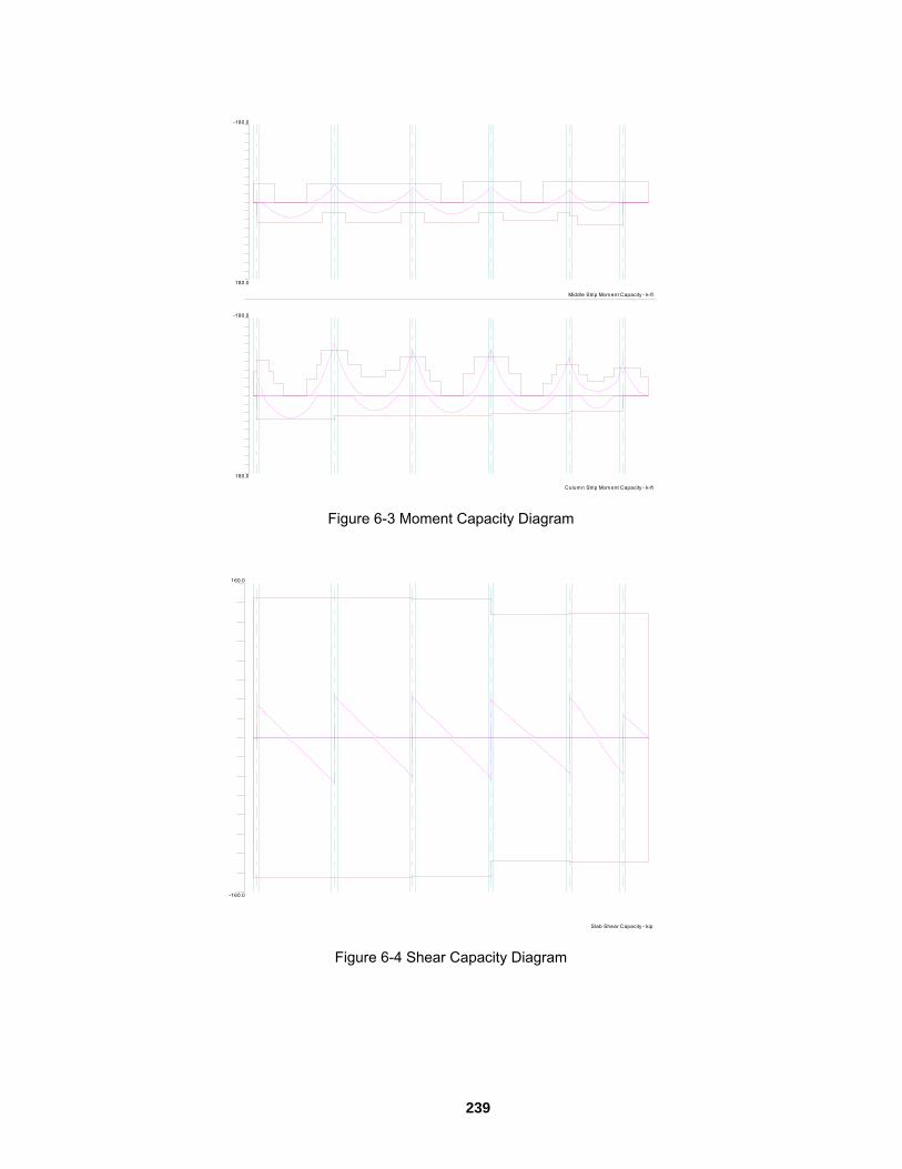
239
Colum n Strip Mom ent Capacity - k-ft
-180.0
180.0
Middle Strip Mom ent Capacity - k-ft
-180.0
180.0
Figure 6-3 Moment Capacity Diagram
Slab Shear Capacity - kip
160.0
-160.0
Figure 6-4 Shear Capacity Diagram

240
Deflection Diagram - in
0.058
-0.058
LEGEND:
De ad L oa d
Li ve L oa d
To ta l De fl ectio n
Figure 6-5 Deflection Diagram
Colum n Strip Flexural Rebars
Middle Strip Flexural Rebars
8-#4c2-#4
5-#4
5-#4
7-#4
6-#4
9-#4c
5-#4
8-#4c
3-#4
8-#4c
6 -#4
5 -#4
6-#5
5-#5
8-#4c
6-#5
5-#5
5-#4
4-#4
7-#4c
3 -#4
6-#4c
2-#4
6-#4c
8 -#4 c
8-#4c
8-#4
8-#4
4-#4c4-#4
8-#4c
4-#4c4-#4
8 -#4
9-#4
4-#4c4-#4
9-#4
9-#4
4-#4c3-#4
9-#4c
5-#4c4-#4
9 -#4 c
Figure 6-6 Reinforcement Diagram

241
Beam-Supported Slab Problem Description
Analyze and design an exterior strip shown in Figure 6-7.
Figure 6-7 Example beam-supported slab

242
Calculation Results - Text Output
The following listing contains the first three sections of the result report for Example 2.
ooooooo oooooo ooooo oooooooo oooooooo ooooooo oo oo oo oo oo oo oo oo oo oo oo oooooooo oo ooooooo ooooo ooooooo oo oo ooooooo ooooo oo oo oo oo oo oo oooooooo oo oo oo oooooo oo oo oooooo o o oooooooo oo ooooo oo oo oo o oo oo oooo oo o oo oo oooooo oo oooooo oooooo oooo oo oo oo oo oo oo oo oo oo oo oo oooooooo oo o oo oo oo oo oooooo ooo ooooo o ooooo ============================================================================= pcaSlab V1.01 (TM) A Computer Program for Analysis and Design of Slab Systems ============================================================================= Copyright © 2000-2003, Portland Cement Association All rights reserved Licensee stated above acknowledges that Portland Cement Association (PCA) is not and cannot be responsible for either the accuracy or adequacy of the material supplied as input for processing by the pcaSlab computer program. Furthermore, PCA neither makes any warranty expressed nor implied with respect to the correctness of the output prepared by the pcaSlab program. Although PCA has endeavored to produce pcaSlab error free the program is not and cannot be certified infallible. The final and only responsibility for analysis, design and engineering documents is the licensees. Accordingly, PCA disclaims all responsibility in contract, negligence or other tort for any analysis, design or engineering documents prepared in connection with the use of the pcaSlab program. ============================================================================================= [1] INPUT ECHO ============================================================================================= General Information: ==================== File name: C:\Program Files\PCA\pcaslab\Examples Adoss\pltbms.slb Project: FLAT PLATE WITH BEAMS Frame: Example 4 Engineer: PCA Code: ACI 318-99 Mode: Design Rebar Database: ASTM A615 Number of supports = 6 + Left cantilever + Right cantilever Live load pattern ratio = 75% Minimum free edge for punching shear = 10 times slab thickness Deflections are based on cracked section properties. Material Properties: ==================== Slabs|Beams Columns ------------ ------------ wc = 150 150 lb/ft3 f'c = 4 4 ksi Ec = 3834.25 3834.25 ksi fr = 0.4743 0.4743 ksi fy = 60 ksi, Bars are not epoxy-coated fyv = 60 ksi Es = 29000 ksi Rebar Database: =============== Units: Db (in), Ab (in^2), Wb (lb/ft) Size Db Ab Wb Size Db Ab Wb ---- -------- -------- -------- ---- -------- -------- -------- #3 0.38 0.11 0.38 #4 0.50 0.20 0.67 #5 0.63 0.31 1.04 #6 0.75 0.44 1.50 #7 0.88 0.60 2.04 #8 1.00 0.79 2.67 #9 1.13 1.00 3.40 #10 1.27 1.27 4.30 #11 1.41 1.56 5.31 #14 1.69 2.25 7.65

243
#18 2.26 4.00 13.60 Span Data: ========== Slabs: L1, wL, wR (ft); t (in) Span Loc L1 t wL wR Hmin ---- ---- -------- -------- -------- -------- -------- 1 ExtL 0.833 8.00 2.167 10.000 4.87 LC 2 ExtL 24.000 8.00 2.167 10.000 5.35 3 ExtL 24.000 8.00 2.167 10.000 5.35 4 ExtL 24.000 8.00 2.167 10.000 5.35 5 ExtL 24.000 8.00 2.167 10.000 5.35 6 ExtL 24.000 8.00 2.167 10.000 5.35 7 ExtL 0.833 8.00 2.167 10.000 4.87 RC Ribs and Longitudinal Beams: b, h, Sp (in) __________Ribs____________ _______Beams_____ Span b h Sp b h ---- -------- -------- -------- -------- -------- 1 0.00 0.00 0.00 52.00 18.00 2 0.00 0.00 0.00 52.00 18.00 3 0.00 0.00 0.00 52.00 18.00 4 0.00 0.00 0.00 52.00 18.00 5 0.00 0.00 0.00 52.00 18.00 6 0.00 0.00 0.00 52.00 18.00 7 0.00 0.00 0.00 52.00 18.00 Support Data: ============= Columns: c1a, c2a, c1b, c2b (in); Ha, Hb (ft) Supp c1a c2a Ha c1b c2b Hb Red% ---- -------- -------- -------- -------- -------- -------- ---- 1 20.00 20.00 8.000 20.00 20.00 11.000 100 2 20.00 20.00 8.000 20.00 20.00 11.000 100 3 20.00 20.00 8.000 20.00 20.00 11.000 100 4 20.00 20.00 8.000 20.00 20.00 11.000 100 5 20.00 20.00 8.000 20.00 20.00 11.000 100 6 20.00 20.00 8.000 20.00 20.00 11.000 100 Transverse Beams: b, h, Ecc (in) Supp b h Ecc ---- -------- -------- -------- 1 72.00 18.00 26.00 2 72.00 18.00 0.00 3 72.00 18.00 0.00 4 72.00 18.00 0.00 5 72.00 18.00 0.00 6 72.00 18.00 -26.00 Load Data: ========== Load Cases and Combinations: Case SELF Dead Live Type DEAD DEAD LIVE U1 1.400 1.400 1.700 Span Loads: Span Case Wa La Wb Lb ---- -------- ------------ ------------ ------------ ------------ Line Loads - Wa | Wb (lb/ft), La | Lb (ft): 6 Live 500 2.5 500 10 Area Loads - Wa (lb/ft2): 1 Dead 10 2 Dead 10 3 Dead 10 4 Dead 10 5 Dead 10 6 Dead 10 7 Dead 10 1 Live 100 2 Live 100 3 Live 100 4 Live 100 5 Live 100 6 Live 100 7 Live 100 Reinforcement Criteria: ======================= _____Top bars___ ___Bottom bars__ ____Stirrups____ Min Max Min Max Min Max ------- ------- ------- ------- ------- ------- Slabs and Ribs: Bar Size #4 #8 #4 #8 Bar spacing 6.00 18.00 6.00 18.00 in Reinf ratio 0.18 2.00 0.18 2.00 % Cover 1.20 1.20 in Beams: Bar Size #4 #14 #4 #14 #3 #5 Bar spacing 1.00 18.00 1.00 18.00 6.00 18.00 in Reinf ratio 0.20 2.00 0.20 2.00 %

244
Cover 1.20 1.20 in ============================================================================================= [2] DESIGN RESULTS ============================================================================================= Top Reinforcement: ================== Units: Width (ft), Mmax (k-ft), Xmax (ft), As (in^2), Sp (in) Span Strip Zone Width Mmax Xmax AsMin AsMax SpReq AsReq Bars ---- ------ ------ -------- ------------ -------- -------- -------- -------- -------- ------- 1 Column Left 2.83 0.00 0.000 0.490 0.000 11.333 0.000 3-#4 Middle 2.83 0.00 0.000 0.490 0.000 0.000 0.000 3-#4 Right 2.83 0.00 0.000 0.490 4.454 11.333 0.000 3-#4 Middle Left 5.00 0.00 0.000 0.864 7.860 12.000 0.000 5-#4 Middle 5.00 0.00 0.000 0.864 7.860 0.000 0.000 5-#4 Right 5.00 0.00 0.000 0.864 7.860 12.000 0.000 5-#4 Beam Left 4.33 0.00 0.000 1.721 17.212 6.008 0.000 9-#4 Middle 4.33 0.00 0.000 1.721 17.212 0.000 0.000 9-#4 Right 4.33 0.00 0.000 1.721 17.212 6.008 0.000 9-#4 2 Column Left 2.83 17.09 0.833 0.490 4.454 11.333 0.594 3-#4 Middle 2.83 0.00 0.000 0.000 0.000 0.000 0.000 --- Right 2.83 32.43 23.167 0.490 4.412 8.500 1.165 4-#5 Middle Left 5.00 12.95 0.833 0.864 7.860 12.000 0.444 5-#4 Middle 5.00 0.00 0.000 0.000 0.000 0.000 0.000 --- Right 5.00 24.58 23.167 0.864 7.860 12.000 0.850 5-#4 Beam Left 4.33 96.82 0.833 1.753 17.212 6.008 1.318 9-#4 Middle 4.33 0.00 0.000 0.000 0.000 0.000 0.000 --- Right 4.33 183.79 23.167 2.869 17.212 3.433 2.534 15-#4 3 Column Left 2.83 29.24 0.833 0.490 4.412 8.500 1.045 4-#5 Middle 2.83 0.00 0.000 0.000 0.000 0.000 0.000 --- Right 2.83 26.77 23.167 0.490 4.454 6.800 0.943 5-#4 Middle Left 5.00 22.16 0.833 0.864 7.860 12.000 0.765 5-#4 Middle 5.00 0.00 0.000 0.000 0.000 0.000 0.000 --- Right 5.00 20.29 23.167 0.864 7.860 12.000 0.699 5-#4 Beam Left 4.33 165.71 0.833 2.869 17.212 3.433 2.278 15-#4 Middle 4.33 0.00 0.000 0.000 0.000 0.000 0.000 --- Right 4.33 151.69 23.167 2.768 17.212 3.433 2.081 15-#4 4 Column Left 2.83 27.37 0.833 0.490 4.454 6.800 0.966 5-#4 Middle 2.83 0.00 0.000 0.000 0.000 0.000 0.000 --- Right 2.83 27.19 23.167 0.490 4.454 6.800 0.959 5-#4 Middle Left 5.00 20.74 0.833 0.864 7.860 12.000 0.715 5-#4 Middle 5.00 0.00 0.000 0.000 0.000 0.000 0.000 --- Right 5.00 20.61 23.167 0.864 7.860 12.000 0.711 5-#4 Beam Left 4.33 155.10 0.833 2.832 17.212 3.433 2.129 15-#4 Middle 4.33 0.00 0.000 0.000 0.000 0.000 0.000 --- Right 4.33 154.09 23.167 2.813 17.212 3.433 2.115 15-#4 5 Column Left 2.83 26.40 0.833 0.490 4.454 6.800 0.930 5-#4 Middle 2.83 0.00 0.000 0.000 0.000 0.000 0.000 --- Right 2.83 30.05 23.167 0.490 4.412 8.500 1.076 4-#5 Middle Left 5.00 20.01 0.833 0.864 7.860 12.000 0.690 5-#4 Middle 5.00 0.00 0.000 0.000 0.000 0.000 0.000 --- Right 5.00 22.78 23.167 0.864 7.860 12.000 0.787 5-#4 Beam Left 4.33 149.62 0.833 2.729 17.212 3.433 2.052 15-#4 Middle 4.33 0.00 0.000 0.000 0.000 0.000 0.000 --- Right 4.33 170.30 23.167 2.869 17.212 3.433 2.343 15-#4 6 Column Left 2.83 34.35 0.833 0.490 4.412 8.500 1.238 4-#5 Middle 2.83 0.00 0.000 0.000 0.000 0.000 0.000 --- Right 2.83 18.00 23.167 0.490 4.454 8.500 0.626 4-#4 Middle Left 5.00 26.04 0.833 0.864 7.860 12.000 0.902 5-#4 Middle 5.00 0.00 0.000 0.000 0.000 0.000 0.000 --- Right 5.00 13.64 23.167 0.864 7.860 12.000 0.468 5-#4 Beam Left 4.33 194.66 0.833 2.869 17.212 3.433 2.688 15-#4 Middle 4.33 0.00 0.000 0.000 0.000 0.000 0.000 --- Right 4.33 101.98 23.167 1.848 17.212 5.340 1.389 10-#4 7 Column Left 2.83 0.00 0.833 0.490 4.454 8.500 0.000 4-#4 Middle 2.83 0.00 0.833 0.490 0.000 0.000 0.000 3-#4 Right 2.83 0.00 0.833 0.490 0.000 11.333 0.000 3-#4 Middle Left 5.00 0.00 0.833 0.864 7.860 12.000 0.000 5-#4 Middle 5.00 0.00 0.833 0.864 7.860 0.000 0.000 5-#4 Right 5.00 0.00 0.833 0.864 7.860 12.000 0.000 5-#4

245
Beam Left 4.33 0.00 0.833 1.721 17.212 5.340 0.000 10-#4 Middle 4.33 0.00 0.833 1.721 17.212 0.000 0.000 9-#4 Right 4.33 0.00 0.833 1.721 17.212 6.008 0.000 9-#4 Top Bar Details: ================ Units: Length (ft) _____________Left______________ ___Continuous__ _____________Right_____________ Span Strip Bars Length Bars Length Bars Length Bars Length Bars Length ---- ------ ------- ------- ------- ------- ------- ------- ------- ------- ------- ------- 1 Column --- --- 3-#4 0.83 --- --- Middle --- --- 5-#4 0.83 --- --- Beam --- --- 9-#4 0.83 --- --- 2 Column 2-#4 8.20 1-#4 5.30 --- 2-#5 8.35 2-#5 5.30 Middle 5-#4 5.75 --- --- 5-#4 8.35 --- Beam 5-#4 5.36 4-#4 2.81 --- 8-#4 8.35 7-#4 3.76 3 Column 2-#5 8.65 2-#5 5.30 --- 3-#4 8.20 2-#4 5.30 Middle 5-#4 8.65 --- --- 5-#4 8.15 --- Beam 8-#4 8.65 7-#4 3.42 --- 8-#4 8.15 7-#4 3.08 4 Column 3-#4 8.20 2-#4 5.30 --- 3-#4 8.20 2-#4 5.30 Middle 5-#4 8.15 --- --- 5-#4 8.15 --- Beam 8-#4 8.15 7-#4 3.16 --- 8-#4 8.15 7-#4 3.13 5 Column 3-#4 8.20 2-#4 5.30 --- 2-#5 8.65 2-#5 5.30 Middle 5-#4 8.15 --- --- 5-#4 8.65 --- Beam 8-#4 8.15 7-#4 3.03 --- 8-#4 8.65 7-#4 3.53 6 Column 2-#5 8.35 2-#5 5.30 --- 2-#4 8.20 2-#4 5.30 Middle 5-#4 8.35 --- --- 5-#4 5.75 --- Beam 8-#4 8.35 7-#4 3.87 --- 5-#4 5.36 5-#4 2.93 7 Column 1-#4 0.83 --- 3-#4 0.83 --- --- Middle --- --- 5-#4 0.83 --- --- Beam 1-#4 0.83 --- 9-#4 0.83 --- --- Bottom Reinforcement: ===================== Units: Width (ft), Mmax (k-ft), Xmax (ft), As (in^2), Sp (in) Span Strip Width Mmax Xmax AsMin AsMax SpReq AsReq Bars ---- ------ -------- ------------ -------- -------- -------- -------- -------- ------- 1 Column 2.83 0.00 0.000 0.000 4.454 0.000 0.000 --- Middle 5.00 0.00 0.000 0.000 7.860 0.000 0.000 --- Beam 4.33 0.00 0.000 0.000 17.212 0.000 0.000 --- 2 Column 2.83 16.23 10.857 0.490 4.454 11.333 0.563 3-#4 Middle 5.00 12.30 10.857 0.864 7.860 12.000 0.421 5-#4 Beam 4.33 91.99 10.857 1.721 17.212 6.008 1.251 9-#4 3 Column 2.83 12.40 12.250 0.490 4.454 11.333 0.428 3-#4 Middle 5.00 9.40 12.250 0.864 7.860 12.000 0.321 5-#4 Beam 4.33 70.26 12.250 1.721 17.212 6.008 0.953 9-#4 4 Column 2.83 12.97 12.000 0.490 4.454 11.333 0.448 3-#4 Middle 5.00 9.83 12.000 0.864 7.860 12.000 0.336 5-#4 Beam 4.33 73.49 12.000 1.721 17.212 6.008 0.997 9-#4 5 Column 2.83 12.40 11.750 0.490 4.454 11.333 0.428 3-#4 Middle 5.00 9.40 11.750 0.864 7.860 12.000 0.321 5-#4 Beam 4.33 70.26 11.750 1.721 17.212 6.008 0.953 9-#4 6 Column 2.83 16.97 12.896 0.490 4.454 11.333 0.590 3-#4 Middle 5.00 12.86 12.896 0.864 7.860 12.000 0.441 5-#4 Beam 4.33 96.18 12.896 1.741 17.212 6.008 1.309 9-#4 7 Column 2.83 0.00 0.833 0.000 4.454 0.000 0.000 --- Middle 5.00 0.00 0.833 0.000 7.860 0.000 0.000 --- Beam 4.33 0.00 0.833 0.000 17.212 0.000 0.000 --- Bottom Bar Details: =================== Units: Start (ft), Length (ft) _______Long Bars_______ ______Short Bars_______ Span Strip Bars Start Length Bars Start Length ---- ------- ------- ------- ------- ------- ------- ------- 1 Column --- --- Middle --- --- Beam --- --- 2 Column 3-#4 0.00 24.00 --- Middle 3-#4 0.00 24.00 2-#4 0.00 20.40 Beam 5-#4 0.00 24.00 4-#4 0.00 15.31 3 Column 3-#4 0.00 24.00 --- Middle 3-#4 0.00 24.00 2-#4 3.60 16.80 Beam 5-#4 0.00 24.00 4-#4 10.85 2.80 4 Column 3-#4 0.00 24.00 --- Middle 3-#4 0.00 24.00 2-#4 3.60 16.80 Beam 5-#4 0.00 24.00 4-#4 10.60 2.80

246
5 Column 3-#4 0.00 24.00 --- Middle 3-#4 0.00 24.00 2-#4 3.60 16.80 Beam 5-#4 0.00 24.00 4-#4 10.35 2.80 6 Column 3-#4 0.00 24.00 --- Middle 3-#4 0.00 24.00 2-#4 3.60 20.40 Beam 5-#4 0.00 24.00 4-#4 8.08 15.92 7 Column --- --- Middle --- --- Beam --- --- Flexural Capacity: ================== Units: From, To (ft), As (in^2), PhiMn (k-ft) Span Strip From To AsTop AsBot PhiMn- PhiMn+ ---- ------ --------- --------- ----- ----- ------------ ------------ 1 Column 0.000 0.833 0.60 0.00 -17.26 0.00 Middle 0.000 0.833 1.00 0.00 -28.81 0.00 Beam 0.000 0.833 1.80 0.00 -131.58 0.00 2 Column 0.000 0.833 0.60 0.60 -17.26 17.26 0.833 5.301 0.60 0.60 -17.26 17.26 5.301 8.204 0.40 0.60 -11.60 17.26 8.204 8.650 0.00 0.60 0.00 17.26 8.650 15.350 0.00 0.60 0.00 17.26 15.350 15.646 0.00 0.60 0.00 17.26 15.646 18.699 0.62 0.60 -17.65 17.26 18.699 23.167 1.24 0.60 -34.40 17.26 23.167 24.000 1.24 0.60 -34.40 17.26 Middle 0.000 0.833 1.00 1.00 -28.81 28.81 0.833 5.747 1.00 1.00 -28.81 28.81 5.747 8.650 0.00 1.00 0.00 28.81 8.650 15.350 0.00 1.00 0.00 28.81 15.350 15.646 0.00 1.00 0.00 28.81 15.646 20.400 1.00 1.00 -28.81 28.81 20.400 23.167 1.00 0.60 -28.81 17.45 23.167 24.000 1.00 0.60 -28.81 17.45 Beam 0.000 0.833 1.80 1.80 -131.58 131.58 0.833 2.806 1.80 1.80 -131.58 131.58 2.806 5.359 1.00 1.80 -73.71 131.58 5.359 8.650 0.00 1.80 0.00 131.58 8.650 15.313 0.00 1.80 0.00 131.58 15.313 15.350 0.00 1.00 0.00 73.71 15.350 15.646 0.00 1.00 0.00 73.71 15.646 20.237 1.60 1.00 -117.21 73.71 20.237 23.167 3.00 1.00 -216.55 73.71 23.167 24.000 3.00 1.00 -216.55 73.71 3 Column 0.000 0.833 1.24 0.60 -34.40 17.26 0.833 5.301 1.24 0.60 -34.40 17.26 5.301 8.646 0.62 0.60 -17.65 17.26 8.646 8.650 0.00 0.60 0.00 17.26 8.650 15.350 0.00 0.60 0.00 17.26 15.350 15.796 0.00 0.60 0.00 17.26 15.796 18.699 0.60 0.60 -17.26 17.26 18.699 23.167 1.00 0.60 -28.31 17.26 23.167 24.000 1.00 0.60 -28.31 17.26 Middle 0.000 0.833 1.00 0.60 -28.81 17.45 0.833 3.600 1.00 0.60 -28.81 17.45 3.600 8.646 1.00 1.00 -28.81 28.81 8.646 8.650 0.00 1.00 0.00 28.81 8.650 15.350 0.00 1.00 0.00 28.81 15.350 15.854 0.00 1.00 0.00 28.81 15.854 20.400 1.00 1.00 -28.81 28.81 20.400 23.167 1.00 0.60 -28.81 17.45 23.167 24.000 1.00 0.60 -28.81 17.45 Beam 0.000 0.833 3.00 1.00 -216.55 73.71 0.833 3.421 3.00 1.00 -216.55 73.71 3.421 8.646 1.60 1.00 -117.21 73.71 8.646 8.650 0.00 1.00 0.00 73.71 8.650 10.849 0.00 1.00 0.00 73.71 10.849 13.651 0.00 1.80 0.00 131.58 13.651 15.350 0.00 1.00 0.00 73.71 15.350 15.854 0.00 1.00 0.00 73.71 15.854 20.918 1.60 1.00 -117.21 73.71 20.918 23.167 3.00 1.00 -216.55 73.71 23.167 24.000 3.00 1.00 -216.55 73.71 4 Column 0.000 0.833 1.00 0.60 -28.31 17.26 0.833 5.301 1.00 0.60 -28.31 17.26 5.301 8.204 0.60 0.60 -17.26 17.26 8.204 8.650 0.00 0.60 0.00 17.26 8.650 15.350 0.00 0.60 0.00 17.26 15.350 15.796 0.00 0.60 0.00 17.26 15.796 18.699 0.60 0.60 -17.26 17.26 18.699 23.167 1.00 0.60 -28.31 17.26 23.167 24.000 1.00 0.60 -28.31 17.26 Middle 0.000 0.833 1.00 0.60 -28.81 17.45 0.833 3.600 1.00 0.60 -28.81 17.45 3.600 8.146 1.00 1.00 -28.81 28.81

247
8.146 8.650 0.00 1.00 0.00 28.81 8.650 15.350 0.00 1.00 0.00 28.81 15.350 15.854 0.00 1.00 0.00 28.81 15.854 20.400 1.00 1.00 -28.81 28.81 20.400 23.167 1.00 0.60 -28.81 17.45 23.167 24.000 1.00 0.60 -28.81 17.45 Beam 0.000 0.833 3.00 1.00 -216.55 73.71 0.833 3.156 3.00 1.00 -216.55 73.71 3.156 8.146 1.60 1.00 -117.21 73.71 8.146 8.650 0.00 1.00 0.00 73.71 8.650 10.599 0.00 1.00 0.00 73.71 10.599 13.401 0.00 1.80 0.00 131.58 13.401 15.350 0.00 1.00 0.00 73.71 15.350 15.854 0.00 1.00 0.00 73.71 15.854 20.868 1.60 1.00 -117.21 73.71 20.868 23.167 3.00 1.00 -216.55 73.71 23.167 24.000 3.00 1.00 -216.55 73.71 5 Column 0.000 0.833 1.00 0.60 -28.31 17.26 0.833 5.301 1.00 0.60 -28.31 17.26 5.301 8.204 0.60 0.60 -17.26 17.26 8.204 8.650 0.00 0.60 0.00 17.26 8.650 15.350 0.00 0.60 0.00 17.26 15.350 15.354 0.00 0.60 0.00 17.26 15.354 18.699 0.62 0.60 -17.65 17.26 18.699 23.167 1.24 0.60 -34.40 17.26 23.167 24.000 1.24 0.60 -34.40 17.26 Middle 0.000 0.833 1.00 0.60 -28.81 17.45 0.833 3.600 1.00 0.60 -28.81 17.45 3.600 8.146 1.00 1.00 -28.81 28.81 8.146 8.650 0.00 1.00 0.00 28.81 8.650 15.350 0.00 1.00 0.00 28.81 15.350 15.354 0.00 1.00 0.00 28.81 15.354 20.400 1.00 1.00 -28.81 28.81 20.400 23.167 1.00 0.60 -28.81 17.45 23.167 24.000 1.00 0.60 -28.81 17.45 Beam 0.000 0.833 3.00 1.00 -216.55 73.71 0.833 3.034 3.00 1.00 -216.55 73.71 3.034 8.146 1.60 1.00 -117.21 73.71 8.146 8.650 0.00 1.00 0.00 73.71 8.650 10.349 0.00 1.00 0.00 73.71 10.349 13.151 0.00 1.80 0.00 131.58 13.151 15.350 0.00 1.00 0.00 73.71 15.350 15.354 0.00 1.00 0.00 73.71 15.354 20.466 1.60 1.00 -117.21 73.71 20.466 23.167 3.00 1.00 -216.55 73.71 23.167 24.000 3.00 1.00 -216.55 73.71 6 Column 0.000 0.833 1.24 0.60 -34.40 17.26 0.833 5.301 1.24 0.60 -34.40 17.26 5.301 8.354 0.62 0.60 -17.65 17.26 8.354 8.650 0.00 0.60 0.00 17.26 8.650 15.350 0.00 0.60 0.00 17.26 15.350 15.796 0.00 0.60 0.00 17.26 15.796 18.699 0.40 0.60 -11.60 17.26 18.699 23.167 0.80 0.60 -22.83 17.26 23.167 24.000 0.80 0.60 -22.83 17.26 Middle 0.000 0.833 1.00 0.60 -28.81 17.45 0.833 3.600 1.00 0.60 -28.81 17.45 3.600 8.354 1.00 1.00 -28.81 28.81 8.354 8.650 0.00 1.00 0.00 28.81 8.650 15.350 0.00 1.00 0.00 28.81 15.350 18.253 0.00 1.00 0.00 28.81 18.253 23.167 1.00 1.00 -28.81 28.81 23.167 24.000 1.00 1.00 -28.81 28.81 Beam 0.000 0.833 3.00 1.00 -216.55 73.71 0.833 3.873 3.00 1.00 -216.55 73.71 3.873 8.079 1.60 1.00 -117.21 73.71 8.079 8.354 1.60 1.80 -117.21 131.58 8.354 8.650 0.00 1.80 0.00 131.58 8.650 15.350 0.00 1.80 0.00 131.58 15.350 18.641 0.00 1.80 0.00 131.58 18.641 21.074 1.00 1.80 -73.71 131.58 21.074 23.167 2.00 1.80 -145.90 131.58 23.167 24.000 2.00 1.80 -145.90 131.58 7 Column 0.000 0.833 0.80 0.00 -22.83 0.00 0.833 0.833 0.60 0.00 -17.26 0.00 Middle 0.000 0.833 1.00 0.00 -28.81 0.00 0.833 0.833 1.00 0.00 -28.81 0.00 Beam 0.000 0.833 2.00 0.00 -145.90 0.00 0.833 0.833 1.80 0.00 -131.58 0.00 Longitudinal Beam Shear Reinforcement Required: =============================================== Units: d (in), Start, End (ft), PhiVc, Vu (kip), Av/s (in^2/in) Span d PhiVc Start End Vu Av/s ---- -------- -------- -------- -------- -------- -------- 1 16.55 92.53 0.000 0.000 0.00 0.000 2 16.55 92.53 2.212 5.009 44.52 0.000 5.009 7.805 27.54 0.000 7.805 10.602 14.18 0.000

248
10.602 13.398 12.11 0.000 13.398 16.195 25.25 0.000 16.195 18.991 38.39 0.000 18.991 21.788 52.62 0.043 3 16.55 92.53 2.212 5.009 47.91 0.043 5.009 7.805 33.68 0.000 7.805 10.602 20.54 0.000 10.602 13.398 7.85 0.000 13.398 16.195 18.89 0.000 16.195 18.991 32.04 0.000 18.991 21.788 46.26 0.000 4 16.55 92.53 2.212 5.009 47.14 0.043 5.009 7.805 32.92 0.000 7.805 10.602 19.78 0.000 10.602 13.398 7.29 0.000 13.398 16.195 19.66 0.000 16.195 18.991 32.80 0.000 18.991 21.788 47.03 0.043 5 16.55 92.53 2.212 5.009 45.87 0.000 5.009 7.805 31.65 0.000 7.805 10.602 18.53 0.000 10.602 13.398 8.14 0.000 13.398 16.195 20.93 0.000 16.195 18.991 34.07 0.000 18.991 21.788 48.30 0.043 6 16.55 92.53 2.212 5.009 57.78 0.043 5.009 7.805 41.43 0.000 7.805 10.602 25.90 0.000 10.602 13.398 10.89 0.000 13.398 16.195 15.39 0.000 16.195 18.991 28.76 0.000 18.991 21.788 45.73 0.000 7 16.55 92.53 0.833 0.833 0.00 0.000 Longitudinal Beam Shear Reinforcement Details: ============================================== Units: spacing & distance (in). Span Size Stirrups (2 legs each unless otherwise noted) ---- ---- --------------------------------------------- 1 #3 --- None --- 2 #3 <-- 214.9 --> + 7 @ 7.5 [3L] 3 #3 7 @ 7.5 [3L] + <-- 214.9 --> 4 #3 7 @ 7.5 [3L] + <-- 167.8 --> + 7 @ 7.5 [3L] 5 #3 <-- 214.9 --> + 7 @ 7.5 [3L] 6 #3 7 @ 7.5 [3L] + <-- 214.9 --> 7 #3 --- None --- Beam Shear Capacity: ==================== Units: d, Sp (in), Start, End (ft), PhiVc, PhiVn, Vmax (kip), Av (in^2) Span d PhiVc Start End Av Sp PhiVn Vmax ---- -------- -------- -------- -------- -------- -------- -------- -------- 1 16.55 92.53 0.000 0.833 0.000 ----- 46.26 5.06 2 16.55 92.53 0.000 1.083 0.000 ----- 46.26 57.95 1.083 18.991 0.000 ----- 46.26 51.38 18.991 23.366 0.330 7.5 129.67 62.20 23.366 24.000 0.330 7.5 129.67 66.05 3 16.55 92.53 0.000 1.083 0.330 7.5 129.67 61.34 1.083 5.458 0.330 7.5 129.67 54.76 5.458 23.366 0.000 ----- 46.26 55.85 23.366 24.000 0.000 ----- 46.26 59.69 4 16.55 92.53 0.000 1.083 0.330 7.5 129.67 60.58 1.083 5.458 0.330 7.5 129.67 54.00 5.458 19.440 0.000 ----- 46.26 34.91 19.440 23.815 0.330 7.5 129.67 59.34 23.815 24.000 0.330 7.5 129.67 60.46 5 16.55 92.53 0.000 1.083 0.000 ----- 46.26 59.30 1.083 18.991 0.000 ----- 46.26 52.73 18.991 23.366 0.330 7.5 129.67 57.88 23.366 24.000 0.330 7.5 129.67 61.73 6 16.55 92.53 0.000 1.083 0.330 7.5 129.67 71.21 1.083 5.458 0.330 7.5 129.67 64.64 5.458 23.366 0.000 ----- 46.26 55.31 23.366 24.000 0.000 ----- 46.26 59.16 7 16.55 92.53 0.000 0.833 0.000 ----- 46.26 5.06 Slab Shear Capacity: ==================== Units: b, d (in), Xu (ft), PhiVc, Vu(kip) Span b d Vratio PhiVc Vu Xu ---- -------- -------- -------- ------------ ------------ ------------ 1 94.00 6.55 0.000 66.20 0.00 0.00 2 94.00 6.49 0.000 65.57 0.00 22.63 3 94.00 6.49 0.000 65.57 0.00 1.37 4 94.00 6.55 0.000 66.20 0.00 1.38 5 94.00 6.49 0.000 65.57 0.00 22.63 6 94.00 6.49 0.000 65.57 0.00 1.37 7 94.00 6.55 0.000 66.20 0.00 0.00 Flexural Transfer of Negative Unbalanced Moment at Supports: ============================================================ Units: Width (in), Munb (k-ft), As (in^2)

249
Supp Width Munb Comb Pat AsReq AsProv Additional Bars ---- -------- ------------ ---- ---- -------- -------- --------------- 1 44.00 105.16 U1 All 4.077 0.600 18-#4 2 44.00 43.65 U1 Even 1.572 1.240 2-#5 3 44.00 35.01 U1 Even 1.235 1.000 2-#4 4 44.00 35.74 U1 Even 1.261 1.000 2-#4 5 44.00 49.15 U1 Even 1.782 1.240 2-#5 6 44.00 109.93 U1 All 4.294 0.800 18-#4 Punching Shear Around Columns: ============================== Units: Vu (kip), Munb (k-ft), vu (psi), Phi*vc (psi) Supp Vu vu Munb Comb Pat GammaV vu Phi*vc ---- ------------ -------- ------------ ---- ---- ------ -------- -------- 1 61.09 75.8 131.58 U1 All 0.385 139.0 215.0 2 125.24 97.4 -27.60 U1 All 0.400 106.9 215.0 3 118.12 91.8 5.21 U1 All 0.400 93.6 215.0 4 117.61 91.5 -6.81 U1 All 0.400 93.8 215.0 5 130.79 101.7 39.82 U1 All 0.400 115.5 215.0 6 62.30 77.3 -138.55 U1 All 0.385 143.8 215.0 Maximum Deflections: ==================== Units: Dz (in) __________Frame____________ _______Column Strip________ ________Middle Strip_______ Span Dz(DEAD) Dz(LIVE) Dz(TOTAL) Dz(DEAD) Dz(LIVE) Dz(TOTAL) Dz(DEAD) Dz(LIVE) Dz(TOTAL) ---- -------- -------- --------- -------- -------- --------- -------- -------- --------- 1 0.002 0.001 0.003 0.002 0.001 0.003 0.007 0.004 0.011 2 -0.024 -0.015 -0.039 -0.027 -0.016 -0.043 -0.038 -0.023 -0.061 3 -0.015 -0.010 -0.025 -0.017 -0.011 -0.027 -0.024 -0.015 -0.039 4 -0.016 -0.010 -0.027 -0.018 -0.012 -0.030 -0.026 -0.017 -0.042 5 -0.015 -0.009 -0.024 -0.017 -0.010 -0.027 -0.024 -0.014 -0.038 6 -0.024 -0.017 -0.041 -0.027 -0.019 -0.046 -0.038 -0.027 -0.065 7 0.002 0.001 0.003 0.002 0.001 0.003 0.007 0.004 0.011 Material Takeoff: ================= Reinforcement in the Direction of Analysis ------------------------------------------ Top Steel: 1057.708 lb = 0.715 lb/ft^2 Bottom Steel: 1109.521 lb = 0.750 lb/ft^2 Stirrup: 772.229 lb = 0.522 lb/ft^2 Total steel: 2939.458 lb = 1.986 lb/ft^2 Concrete Volume: 1791.204 ft^3 = 1.210 ft^3/ft^2 ============================================================================================= [3] COLUMN AXIAL FORCES AND MOMENTS ============================================================================================= Units: P (kip), M (k-ft) Supp Case/Patt P (axial) Mb[top] Ma[bottom] ---- ---------- ------------ ------------ ------------ 1 SELF 26.21 -32.76 -34.39 Dead 1.43 -2.04 -2.14 Live-1 14.31 -20.40 -21.41 Live-2 -0.07 3.05 3.21 Live-3 10.80 -18.35 -19.26 Live-4 11.44 -17.79 -18.68 2 SELF 50.65 5.41 5.68 Dead 3.07 0.32 0.33 Live-1 30.70 3.20 3.36 Live-2 11.90 -13.76 -14.44 Live-3 11.12 16.16 16.96 Live-4 23.88 0.60 0.63 3 SELF 47.74 -0.97 -1.01 Dead 2.90 -0.06 -0.06 Live-1 29.04 -0.65 -0.69 Live-2 10.83 15.41 16.18 Live-3 10.96 -15.90 -16.70 Live-4 23.60 0.01 0.01 4 SELF 47.74 0.97 1.01 Dead 2.90 0.06 0.06 Live-1 28.74 1.11 1.17 Live-2 10.83 -15.41 -16.18 Live-3 10.73 16.25 17.06 Live-4 23.60 -0.01 -0.01 5 SELF 50.64 -5.41 -5.68 Dead 3.07 -0.32 -0.33 Live-1 33.97 -6.71 -7.04 Live-2 11.90 13.76 14.44 Live-3 13.57 -18.79 -19.72 Live-4 26.33 -3.24 -3.40 6 SELF 26.21 32.76 34.39 Dead 1.43 2.04 2.14 Live-1 15.02 22.62 23.75

250
Live-2 -0.07 -3.05 -3.21 Live-3 11.33 20.02 21.02 Live-4 11.97 19.46 20.43 Sum SELF 249.18 -0.00 -0.00 Dead 14.80 -0.00 -0.00 Live-1 151.78 -0.82 -0.86 Live-2 45.32 -0.00 -0.00 Live-3 68.51 -0.62 -0.65

251
Calculation Results - Graphical Output
The following diagrams illustrate the graphical output for Example 2.
Mom ent Diagram - k-ft
-350.0
350.0
Shear Diagram - kip
80.0
-80.0
-2.11
-173.05
-293.73
120.52
-266.13-246.38
92.06
-251.59 -250.17
96.29
-243.35-272.46
92.06
-312.29
-180.79
126.02
-2.11
-5.06
57.95
-66.05
61.34
-59.69
60.58
-60.46
59.30
-61.73
71.21
-59.16
5.06
Figure 6-8 Shear and Moment Diagram
Colum n Strip Mom ent Capacity - k-ft
-350.0
350.0
Middle Strip Mom ent Capacity - k-ft
-350.0
350.0
Beam Strip Moment Capacity - k-ft
-350.0
350.0
Figure 6-9 Moment Capacity Diagram

252
Slab Shear Capacity - kip
140.0
-140.0
Beam Shear Capacity - kip
140.0
-140.0
Figure 6-10 Shear Capacity Diagram
Deflection Diagram - in
0 .0 41
-0 .0 41
LEGEND:
De ad L oa d
Li ve L oa d
To ta l De fl ectio n
Figure 6-11 Deflection Diagram

253
Colum n Strip Flexural Rebars
Middle Strip Flexural Rebars
Beam Strip Flexural Rebars
3-#4c2-#4
1-#4
2-#5
2-#5
3-#4c
2-#5
2-#5
3-#4
2-#4
3-#4c
3-#4
2-#4
3-#4
2-#4
3-#4c
3-#4
2-#4
2-#5
2 -#5
3 -#4 c
2-#5
2-#5
2-#4
2-#4
3-#4c
1-#43-#4c
5-#4c5-#4
5-#4
3-#4c2-#4
5-#4
5-#4
3-#4c2-#4
5-#4
5-#4
3-#4c2-#4
5-#4
5-#4
3 -#4 c2-#4
5-#4
5-#4
3-#4c2-#4
5-#4c
9-#4c5-#4
4-#4
8-#4
7 -#4
5-#4c4-#4
7-#[email protected][3L]
8-#4
7-#4
8-#4
7-#4
5-#4c4-#4
7-#[email protected][3L]
8-#4
7-#4
8-#4
7-#4
5-#4c4-#4
7-#[email protected][3L] 7-#[email protected][3L]
8-#4
7 -#4
8-#4
7-#4
5 -#4 c4-#4
7-#[email protected][3L]
8-#4
7-#4
5 -#4
5-#4
5-#4c4-#4
7-#[email protected][3L]
1-#49-#4c
Figure 6-12 Reinforcement Diagram

254
Appendix Appendix A: Conversion Factors Conversion Factors - U.S. to SI
To convert from To Multiply by
in m (1000 mm) 0.02540 ft m 0.304800 lb N (0.001 kN) 4.448222
Kips (1000 lbs) kN 4.448222 plf (lb/ft) N/m 14.59390
psi (lb/in.2) kPa 6.89757 ksi (kips/in.2) MPa 6.894757
psf (lb/ft2) N/m2 (Pa) 47.88026 pcf (lb/ft3) kg/m3 16.018460
ft-kips kN�m 1.355818
Conversion Factors - SI to U.S. To convert from To Multiply by
m (1000 mm) In 39.37008 m ft 3.28084
N (0.001 kN) lb 0.224809 kN Kips (1000 lbs) 0.224809
kN/m plf (lb/ft) 68.52601 MPa psi (lb/in2) 145.0377 MPa ksi (kips/in2) 0.145038
kN/m2 (kPa) psf (lb/ft2) 20.88555 kg/m3 pcf (lb/ft3) 0.062428 kN�m ft-kips 0.737562

255
Appendix B: Bar Sizes ASTM English Bar Sizes - English Units
Size Diameter (in.) Area (in.2) Weight (lb/ft) #3 0.375 0.11 0.376 #4 0.500 0.20 0.668 #5 0.625 0.31 1.043 #6 0.750 0.44 1.502 #7 0.875 0.60 2.044 #8 1.000 0.79 2.670 #9 1.128 1.00 3.400
#10 1.270 1.27 4.303 #11 1.410 1.56 5.313 #14 1.693 2.25 7.650 #18 2.257 4.00 13.600
ASTM English Bar Sizes - Metric Units
Size Diameter (in.) Area (mm2) Weight (kg/m) #3 9.53 71.0 0.560 #4 12.70 129.0 0.994 #5 15.88 200.0 1.552 #6 19.05 283.9 2.235 #7 22.23 387.1 3.042 #8 25.40 509.7 3.973 #9 28.65 645.2 5.060
#10 32.26 819.4 6.404 #11 35.81 1,006.5 7.907 #14 43.00 1,451.6 11.385 #18 57.33 2,580.6 20.240

256
ASTM Metric Bar Sizes - English Units
Size Diameter (in.) Area (in.2) Weight (lb/ft) #10 0.445 0.16 0.053 #15 0.630 0.31 0.126 #20 0.768 0.47 0.158 #25 0.992 0.78 0.264 #30 1.177 1.09 0.369 #35 1.406 1.55 0.527 #45 1.720 2.33 0.791 #55 2.220 3.88 1.319
ASTM Metric Bar Sizes - Metric Units
Size Diameter (mm) Area (mm2) Weight (kg/m) #10 11.30 100.0 0.785 #15 16.00 200.0 1.870 #20 19.50 300.0 2.356 #25 25.20 500.0 3.925 #30 29.90 700.0 5.495 #35 35.70 1,000.0 7.850 #45 43.70 1,500.0 11.775 #55 56.40 2,500.0 19.625
European Bar Sizes - English Units
Size Diameter (in.) Area (in.2) Weight (lb/ft) #6 0.236 0.04 0.015 #8 0.315 0.08 0.027
#10 0.394 0.12 0.041 #12 0.472 0.18 0.060 #14 0.551 0.24 0.081 #16 0.630 0.31 0.106 #20 0.787 0.49 0.166 #25 0.984 0.76 0.259 #28 1.102 0.95 0.325 #32 1.260 1.24 0.424 #40 1.575 1.95 0.663

257
European Bar Sizes - Metric Units
Size Diameter (mm) Area (mm2) Weight (kg/m) #6 6.00 28.3 0.222 #8 8.00 50.3 0.395
#10 10.00 78.5 0.617 #12 12.00 113.0 0.888 #14 14.00 154.0 1.208 #16 16.00 201.0 1.578 #20 20.00 314.0 2.466 #25 25.00 491.0 3.853 #28 28.00 616.0 4.836 #32 32.00 801.0 6.313 #40 40.00 1,256.0 9.865

258
Appendix C: References References
1. Kripanarayanan, K. M., Analysis and Design of Slab Systems, Computer Program User’s Manual, Portland Cement Association, SR184D, 1979.
2. Lee, B. H., Analysis and Design of Flat Plates, Flat Slabs, Waffle Slabs, and Continuous Frames, Portland Cement Association, 1972 (discontinued).
3. CRSI Handbook Based Upon the 1977 ACI Building Code and the 1980 Supplement, Concrete Reinforcing Steel Institute, Schaumburg, Illinois, 60195, 1982.
4. Sozen, M. A., and Siess, C. P., Reinforced Concrete Floor Slabs – Design Methods: Their Evolution and Comparison, Journal of the American Concrete Institute, Proceedings, V. 60, No. 8, August 1963, pp. 999-1028.
5. Hatcher, D. S., Sozen, M. A., and Siess, C. P., Test of a Reinforced Concrete Flat Plate, Proceedings of the American Society of Civil Engineers, V. 91, No. ST5, October 1965, pp. 205-231.
6. Guralnick, S. A., and LaFraugh, R. W., Laboratory Study of a Forty-Five-Foot Square Flat Plate Structure, Journal of the American Concrete Institute, Proceedings, V. 60, No. 9, September 1963, pp. 1107-1185.
7. Hatcher, D. S., Sozen, M. A., and Siess, C. P., Test of a Reinforced Concrete Flat Slab, Proceedings of the American Society of Civil Engineers, V. 95, No. ST6, June 1969, pp. 1051-1072.
8. Jirsa, J. O., Sozen, M. A., and Siess, C. P., Test of a Flat Slab Reinforced with Welded Wire Fabric, Proceedings of the American Society of Civil Engineers, V. 92, No. ST3, June 1966, pp. 199-224.
9. Gamble, W. L., Sozen, M. A., and Siess, C. P., Test of a Two-Way Reinforced Floor Slab, Proceedings of the American Society of Civil Engineers, V. 95, No. ST6, June, 1969, pp. 1073-1096.
10. Vanderbilt, M. D., Sozen, M. A., and Siess, C. P., Test of a Modified Reinforced Concrete Two-Way Slab, Proceedings of the American Society of Civil Engineers, V. 95, No. ST6, June, 1969, pp. 1097-1116.
11. Shewmaker, R. E., Xanthakis, M., and Sozen, M. A., Very Small Scale Reinforced Concrete Multi-Panel Flat Slabs, Civil Engineering Studies, Structural Research Series No. 265, University of Illinois, June 1963, 171 pp.
12. Xanthakis, M., and Sozen, M. A., An Experimental Study of Limit Design in Reinforced Concrete Flat Slabs, Civil Engineering Studies, Structural Research Series No. 277, University of Illinois, December 1963, 159 pp.
13. Nichols, J. R., Statistical Limitations Upon the Steel Requirement in Reinforced Concrete Flat Slab Floors, Transactions of the American Society of Civil Engineers, V. 77, 1914, pp. 1670-1726.

259
14. Gamble, W. L., Sozen, M. A., and Siess, C. P., Measured and Theoretical Bending Moments in Reinforced Concrete Floor Slabs, Civil Engineering Studies, Structural Research Series No. 246, University of Illinois, June 1962, 322 pp.
15. Jirsa, J. O., Sozen, M. A., and Siess, C. P., Pattern Loadings on Reinforced Concrete Floor Slabs, Proceedings of the American Society of Civil Engineers, V. 95, No. ST6, June, 1969, pp. 1117-1137.
16. Corley, W. G., Sozen, M. A., and Siess, C. P., The Equivalent Frame Analysis for Reinforced Concrete Slabs, Civil Engineering Studies, Structural Research Series No. 218, University of Illinois, June, 1961, 166 pp.
17. Jirsa, J. O., Sozen, M. A., and Siess, C. P., The Effects of Pattern Loadings on Reinforced Concrete Floor Slabs, Civil Engineering Studies Structural Research Series No. 269, University of Illinois, July 1963, 145 pp.
18. Corley, W. G., and Jirsa, J. O., Equivalent Frame Analysis for Slab Design, Journal of the American Concrete Institute, Proceedings, V. 67, No. 11, November 1970, pp. 875-884.
19. ETABS84, Computers and Structures, Inc., Berkeley, California, 1984.
20. ICES STRUDL II, Engineering User’s Manual, Vols. 1 and 2, Department of Civil Engineering, Massachusetts Institute of Technology, R68-91/92, Cambridge, Massachusetts, 1968.
21. Hawkins, N. M., Shear Strength of Slabs with Moments Transferred to Columns, Special Publication SP42-35, American Concrete Institute, Detroit, Michigan, 1974, pp. 817-846.
22. ACI Committee 435, Subcommittee 7, Deflections of Continuous Concrete Beams, Journal of the American Concrete Institute, Proceedings V. 70, No. 12, December 1973, pp. 781-787.
23. Nilson, A. H., and Walters, D. B., Jr., Deflection of Two-Way Floor Systems by the Equivalent Frame Method, Journal of the American Concrete Institute, Proceedings, V. 72, No. 5, May, 1975, pp. 210-218.
24. ACI Committee 435, State-of-the-Art Report, Deflection of Two-Way Floor Systems, Special Publication SP43-3, American Concrete Institute, Detroit, Michigan, 1974.
25. Kripanarayanan, K. M., and Branson, D. E., Short-Time Deflections of Flat Plates, Flat Slabs and Two-Way Slabs, Journal of the American Concrete Institute, Proceedings, V. 73, No. 12, December 1976, pp. 686-690.
26. Branson, D. E., Instantaneous and Time-Dependent Deflections of Simple and Continuous Reinforced Concrete Beams, HPR Report No. 7, Pt. I, Alabama Highway Department in Cooperation with U.S. Department of Commerce, Bureau of Public Roads, August 1965.
27. Blakey, F. A., Deformations of an Experimental Lightweight Flat Plate Structure, Commonwealth Scientific and Industrial Research Organization (CSIRO), DBR Reprint No. 185, Civil Engineering Transactions, Institute of Engineers, V. CE 3, No. 1, Australia, March 1961.
28. Taylor, P. J., Long-Term Deflection Calculation Methods for Flat Plates, Constructional Review, V. 43, No. 2, Sydney, Australia, May 1970, pp. 68-74.

260
29. Heiman, J. L., A Comparison of Measured and Calculated Deflections of Flexural Members in Four Reinforced Concrete Buildings, Special Publication JSP43-21, American Concrete Institute, Detroit, Michigan, 1974.
30. Rangan, B. V., Prediction of Long-Term Deflections of Flat Plates and Slabs, Journal of the American Concrete Institute, Proceedings, V. 73, No. 4, April 1976, pp. 223-226.
31. Notes on ACI318-83 – Building Code Requirements for Reinforced Concrete with Design Applications, Portland Cement Association, 1984.
32. Elgabry, A. and Ghali, A., Proposed Revisions to Building Code Requirements for Reinforced Concrete (ACI 318-83) (Revised 1986), ACI Structural Journal, V. 86 No. 3, May-June 1989, pp. 327-328.
33. Notes on ACI318-95 – Building Code Requirements for Reinforced Concrete with Design Applications, Portland Cement Association PCA, 1996.
34. Manual of Standard Practice, Concrete Reinforcing Steel Institute CRSI, March 2001.
35. Reinforced Concrete, Mechanics & Design, 3rd ed. James McGregor, Prentice Hall, 1997.
36. Nilson, A. and Winter, G., Design of Concrete Structures, McGraw-Hill, New York, 1997.
37. Wang, C. K. and Salmon, C. G., "Reinforced Concrete Design" 6th Ed., Addison-Wesley, 1998.
38. A23.3-94 Design of Concrete Structures, Structures Design, Canadian Standards Association CSA, December 1994.
39. Concrete Design Handbook, Cement Association of Canada CAC, 2nd Ed., 2001.
40. Building Code Requirements for Structural Concrete (318-99) and Commentary (318R-99), American Concrete Institute ACI, Detroit, Michigan, June 1999.
41. Building Code Requirements for Structural Concrete (318-02) and Commentary (318R-02), American Concrete Institute ACI, Detroit, Michigan, January 2002.
42. James R. Cagley, Changing from ACI 318-99 to ACI 318-02 What’s New? Concrete International, June 2001.

261
Index
A ASTM English Bar Sizes - English Units................................................................................ 254 ASTM English Bar Sizes - Metric Units.................................................................................. 254 ASTM Metric Bar Sizes - English Units .................................................................................. 255 ASTM Metric Bar Sizes - Metric Units .................................................................................... 255
B Bug Report Form ......................................................................................................................... 20
C Calculation Results - Graphical Output.................................................................................237, 250 Calculation Results - Text output..........................................................................................230, 241 Cascade ...................................................................................................................................... 218 Column Axial Forces And Moments............................................................................................ 226 Conversion Factors - SI to U.S............................................................................................... 253 Conversion Factors - U.S. to SI............................................................................................... 253 Copy Bitmap BMP file ............................................................................................................... 214 Copy Meta File EMF file ........................................................................................................... 214 Copyright Information ..................................................................................................................... 7
D Data Input Wizard...................................................................................................................... 154 Defining Beam Bars..................................................................................................................... 176 Design Results ........................................................................................................................... 223 Drop-down Menu ....................................................................................................................... 105
E Elevated View ........................................................................................................................... 196 European Bar Sizes - English Units........................................................................................ 255 European Bar Sizes - Metric Units.......................................................................................... 256 EVALUATION SOFTWARE LICENSE AGREEMENT ............................................................ 8
G Graphical Output.................................................................................................................227, 228
I Input Dialog Windows ............................................................................................................... 143 Input Echo................................................................................................................................... 221 Input Wizard ............................................................................................................................... 143 Isometric View.......................................................................................................................... 199
L Loads...................................................................................................................................200, 201
M Method of Solution ...................................................................................................................... 41 Most Resently Used Files MRU .............................................................................................. 153

262
O Obtaining the Program Version ............................................................................................... 219 Open ADOSS Files ...................................................................................................................... 151 Opening Help in Contents mode ............................................................................................. 219 Opening HELP in Index Mode ................................................................................................. 219 Output Dialog Windows ............................................................................................................ 149 Output Elements........................................................................................................................... 221
P Plan View ................................................................................................................................... 194 Pop-up Menu.............................................................................................................................. 110 Print Preview................................................................................................................................ 213 Print the Current View Window ............................................................................................... 211 Problem Description..................................................................................................................... 240 Program Capacity........................................................................................................................... 22 Program Features........................................................................................................................ 22 Program Version........................................................................................................................ 221 Purchasing and Licensing Process........................................................................................... 34
R References ................................................................................................................................. 257 Remaining Commands ............................................................................................................. 218 Removing the Program............................................................................................................... 40 Running pcaSlab ......................................................................................................................... 40
S Saving Results Report .................................................................................................................. 202 Segmental Deflections ................................................................................................................. 227 Segmental Moment And Shear - Envelopes................................................................................. 227 Segmental Moment And Shear - Load Cases............................................................................... 226 Segmental Moment And Shear - Load Combinations.................................................................. 227 Side View .................................................................................................................................... 197 SOFTWARE LICENSE AGREEMENT..................................................................................... 14 Solve Options ........................................................................................................................... 190 Status Bar ................................................................................................................................... 116 System Requirements ................................................................................................................ 25
T Terms and Conventions.................................................................................................................. 26 The Control Menu...................................................................................................................... 139 Tile Horizontal ............................................................................................................................ 218 Tile Vertical................................................................................................................................. 218
V View Windows............................................................................................................................ 115