pcan-router - user manual › produktcd › pdf › english › ... · connectors can2 or can1 (see...
TRANSCRIPT

Universal Programmable CAN Converter
User Manual
PCAN-Router
Document version 1.5.0 (2019-03-12)
PCAN-Router – User Manual
2
Relevant products
Product Name Model Part number
PCAN-Router 2 D-Sub connectors, additional digital input
IPEH-002210
PCAN-Router Screw terminal block, additional serial interface
IPEH-002210-P
PCAN-Router opto-decoupled
2 D-Sub connectors, galvanic isolation for connector CAN2, additional digital input
IPEH-002211
PCAN® is a registered trademark of PEAK-System Technik GmbH. CANopen® and CiA® are registered community trade marks of CAN in Automation e.V.
All other product names mentioned in this document may be the trademarks or registered trademarks of their respective companies. They are not explicitly marked by “™” and “®”.
© 2019 PEAK-System Technik GmbH Duplication (copying, printing, or other forms) and the electronic distribution of this document is only allowed with explicit permission of PEAK-System Technik GmbH. PEAK-System Technik GmbH reserves the right to change technical data without prior announcement. The general business conditions and the regulations of the license agreement apply. All rights are reserved.
PEAK-System Technik GmbH Otto-Roehm-Strasse 69 64293 Darmstadt Germany
Phone: +49 (0)6151 8173-20 Fax: +49 (0)6151 8173-29
www.peak-system.com [email protected]
Document version 1.5.0 (2019-03-12)
PCAN-Router – User Manual
3
Contents
1 Introduction 5 1.1 Properties at a Glance 5 1.2 Scope of Supply 6 1.3 Prerequisites for Operation 7
2 Connectors and Coding Solder Jumpers 8 2.1 D-Sub Connectors 9
2.1.1 Supplying External Devices via the CAN Connector (D-Sub only) 11
2.2 Screw Terminal Block 12 2.3 J4 Connector Panel: Serial Ports 13 2.4 J5 Connector Panel: JTAG Ports 14 2.5 Coding Solder Jumpers 15
3 Operation 17
4 Software 18 4.1 Installing the GNU ARM Toolchain 18 4.2 Library 19 4.3 Firmware Examples 19
4.3.1 Compiling a Firmware Example 20
5 Firmware Upload 21 5.1 Uploading Firmware via CAN 21
5.1.1 System Requirements 21 5.1.2 Preparing Hardware and Software 22 5.1.3 Uploading the Firmware 23
5.2 Uploading Firmware via the Serial Connections 26
6 Technical Specifications 28

PCAN-Router – User Manual
4
Appendix A CE Certificate 30
Appendix B Dimension Drawings 31
Appendix C Port Assignment of the Microcontroller 32
PCAN-Router – User Manual
5
1 Introduction
The PCAN-Router is a dual-channel CAN module whose NXP LPC21 series programmable microcontroller provides the option of using the CAN messages on both channels on a flexible basis. This gives a whole range of options for manipulation, evaluation, filtering, and routing of CAN messages.
Using the supplied library and the Yagarto GNU ARM toolchain (contains the GNU Compiler Collection GCC for C and C++), custom firmware can be created and then transferred to the module via CAN. At delivery, the PCAN- Router is equipped with a demo firmware that forwards CAN messages 1:1 between both channels at 500 kbit/s. The corresponding source code is included as example in the scope of supply.
The module is installed in an aluminum profile casing, and is shipped in versions with two D-Sub connectors or a screw terminal block.
1.1 Properties at a Glance
NXP LPC21 series microcontroller (16/32-bit ARM CPU)
32 kByte EEPROM
Two High-speed CAN channels (ISO 11898-2) with bit rates from 40 kbit/s up to 1 Mbit/s
Complies with CAN specifications 2.0 A/B
Galvanic isolation of the D-Sub connector CAN 2 (only applies to the opto-decoupled model)
Status signaling with two 2-color LEDs

PCAN-Router – User Manual
6
Connection via two 9-pin D-Sub connectors or one 10-pole screw terminal block (Phoenix)
Additional digital input (only applies to models with D-Sub connectors)
Aluminum casing, optionally available with DIN rail mounting on request
Supply voltage from 8 to 30 V
Extended operating temperature range of -40 to 85 °C (-40 to 185 °F)
Import of a new firmware via CAN
Additional serial RS-232 interface (only applies to model with screw terminal block)
1.2 Scope of Supply
PCAN-Router in aluminum casing
IPEH-002210-P: mating connector (Phoenix)1
Windows development software (Yagarto GNU ARM toolchain, flash program)
Library with programming examples
Manual in PDF format
1 Phoenix Contact MC 1,5/10-ST-3,81 - 1803659

PCAN-Router – User Manual
7
1.3 Prerequisites for Operation
Voltage supply within a range of 8 to 26 V DC (up to 30 V with IPEH-002210(-P) from ser. no. 01000 and IPEH-002211 from ser. no. 00020)
For uploading a new firmware via CAN:
CAN interface of the PCAN series for the computer (e.g. PCAN-USB)
Operating system Windows 10, 8.1, and 7 (32/64-bit)
PCAN-Router – User Manual
8
2 Connectors and Coding Solder Jumpers
Depending on the model the PCAN-Router has the following connectors:
two 9-pin D-Sub connectors (IPEH-002210/11)
one 10-pin screw terminal block (IPEH-002210-P)
For direct access to the serial and debugging ports of the micro-controller, additional – yet not equipped – connector panels are available on the board of the PCAN-Router.
Furthermore the PCB has four coding solder jumpers in order to assign a fixed status to the corresponding input bits of the micro-controller. A concrete application is to identify a PCAN-Router on the CAN bus for a firmware upload, especially if there are several routers connected and in operation.
The following subsections describe each connector assignment.

PCAN-Router – User Manual
9
2.1 D-Sub Connectors
(IPEH-002210 and IPEH-002211)
The two D-Sub connectors are used for the CAN channels CAN1 and CAN2.
The voltage supply can be done via both connectors, with the opto-decoupled model only via connector CAN1. The supply connections +Ub1 and +Ub2 are connected internally in a reactionless configura-tion. This means that different power sources can be connected if applicable.
Connector CAN1 additionally offers an input to activate the bootloader named Boot CAN1 (see also section 5.1 Uploading Firmware via CAN on page 21).
Connectors CAN2 or CAN1 (see assignment tables below) have an additional digital input named Din0 which can be utilized by the microcontroller.

PCAN-Router – User Manual
10
Pin distribution D-Sub connector
PCAN-Router IPEH-002210:
Pin Function connector CAN1 Function connector CAN2
1 +5 V for external devices (optional)2 +5 V for external devices (optional)2
2 CAN1_L CAN2_L
3 GND GND
4 Reserved Not used
5 SHIELD SHIELD
6 Boot CAN1 (High-active) Not used
7 CAN1_H CAN2_H
8 Not used Din0 (Low-active)
9 Supply +Ub13 Supply +Ub2
3
PCAN-Router opto-decoupled IPEH-002211:
Pin Function connector CAN1 Function connector CAN2
1 +5 V for external devices (optional)2 +5 V for external devices (optional, via DC/DC converter)2
2 CAN1_L CAN2_L
3 GND1 GND2
4 Reserved Not used
5 SHIELD SHIELD
6 Boot CAN1 (High-active) Not used
7 CAN1_H CAN2_H
8 Din0 (Low-active) Not used
9 Supply +Ub14 Not used
2 See following subsection 2.1.1 3 8 - 26 V DC, up to 30 V from ser. no. 01000 4 8 - 26 V DC, up to 30 V from ser. no. 00020
PCAN-Router – User Manual
11
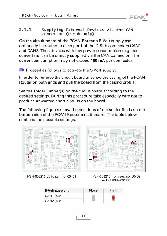
2.1.1 Supplying External Devices via the CAN Connector (D-Sub only)
On the circuit board of the PCAN-Router a 5-Volt supply can optionally be routed to each pin 1 of the D-Sub connectors CAN1 and CAN2. Thus devices with low power consumption (e.g. bus converters) can be directly supplied via the CAN connector. The current consumption may not exceed 100 mA per connector.
Proceed as follows to activate the 5-Volt supply:
In order to remove the circuit board unscrew the casing of the PCAN-Router on both ends and pull the board from the casing profile.
Set the solder jumper(s) on the circuit board according to the desired settings. During this procedure take especially care not to produce unwanted short circuits on the board.
The following figures show the positions of the solder fields on the bottom side of the PCAN-Router circuit board. The table below contains the possible settings.
IPEH-002210 up to ser. no. 00458
IPEH-002210 from ser. no. 00459
and all IPEH-002211
5-Volt supply None Pin 1
CAN1 (R35)
CAN2 (R36)

PCAN-Router – User Manual
12
2.2 Screw Terminal Block
(IPEH-002210-P)
Apart from power supply and CAN channels, the screw terminal block includes connections for a serial interface with RS-232 levels.
Terminal Function
1 Supply +Ub5
2 GND
3 CAN1_L
4 CAN1_H
5 CAN2_L
6 CAN2_H
7 Boot CAN1 (High-active)
8 Reserved
9 RS-232 RxD
10 RS-232 TxD
For further connection details that are not needed for programming of the PCAN-Router because of implementation in a library, see also Appendix C Port Assignment of the Microcontroller on page 32.
5 8 - 26 V DC, up to 30 V from ser. no. 01000
PCAN-Router – User Manual
13
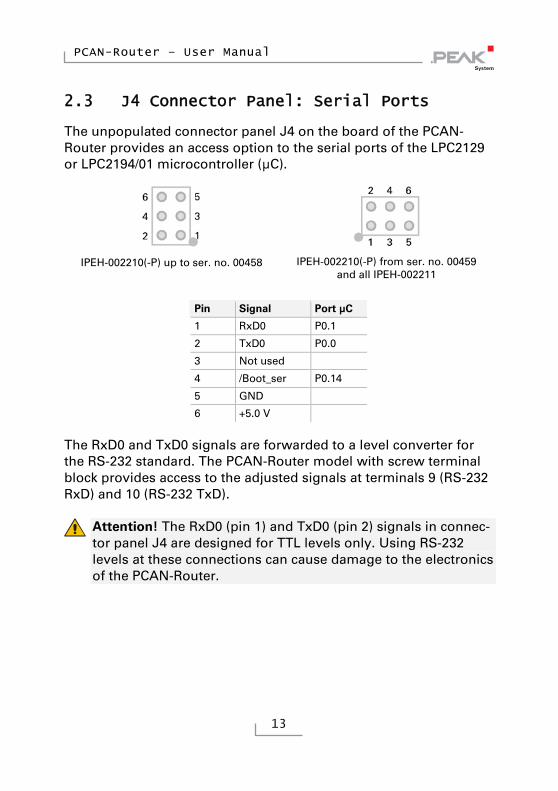
2.3 J4 Connector Panel: Serial Ports
The unpopulated connector panel J4 on the board of the PCAN-Router provides an access option to the serial ports of the LPC2129 or LPC2194/01 microcontroller (μC).
IPEH-002210(-P) up to ser. no. 00458
IPEH-002210(-P) from ser. no. 00459
and all IPEH-002211
Pin Signal Port μC
1 RxD0 P0.1
2 TxD0 P0.0
3 Not used
4 /Boot_ser P0.14
5 GND
6 +5.0 V
The RxD0 and TxD0 signals are forwarded to a level converter for the RS-232 standard. The PCAN-Router model with screw terminal block provides access to the adjusted signals at terminals 9 (RS-232 RxD) and 10 (RS-232 TxD).
Attention! The RxD0 (pin 1) and TxD0 (pin 2) signals in connec-tor panel J4 are designed for TTL levels only. Using RS-232 levels at these connections can cause damage to the electronics of the PCAN-Router.

PCAN-Router – User Manual
14
2.4 J5 Connector Panel: JTAG Ports
The unpopulated connector panel J5 on the circuit board of the PCAN-Router provides an access option to the JTAG ports of the LPC2129 or LPC2194/01 microcontroller (μC) for hardware debugging.
IPEH-002210(-P) up to ser. no. 00458
IPEH-002210(-P) from ser. no. 00459
and all IPEH-002211
Pin Signal Port μC Internal wiring
1, 2 GND
3 /Reset /Reset Pull-up
4 3.3 V
5 TCK P1.29 Pull-down (R30)
6 TMS P1.30 Pull-up
7 TDO P1.27 Pull-up
8 TDI P1.28 Pull-up
9 RTCK P1.26 Pull-down (R31)
10 TRST P1.31 Pull-up
If constant internal pull-down wiring of the TCK or RTCK signals is not suitable for your purposes, you can remove the respective pull-down resistor on the circuit board of the PCAN-Router by soldering it out. Both resistors (each 10 k) are located next to the J5 connector panel J5 (see figures).
IPEH-002210(-P) up to ser. no. 00458
IPEH-002210(-P) from ser. no. 00459 and all IPEH-002211 Top side of the PCB | Bottom side of the PCB
PCAN-Router – User Manual
15
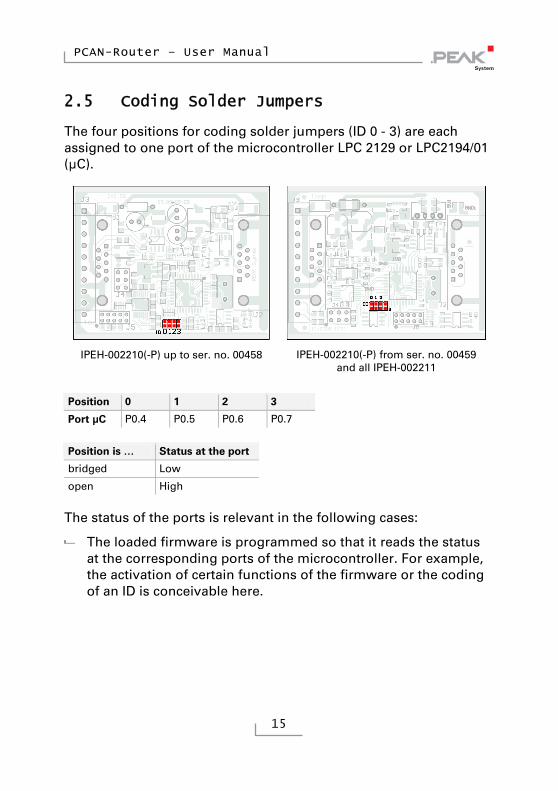
2.5 Coding Solder Jumpers
The four positions for coding solder jumpers (ID 0 - 3) are each assigned to one port of the microcontroller LPC 2129 or LPC2194/01 (μC).
IPEH-002210(-P) up to ser. no. 00458
IPEH-002210(-P) from ser. no. 00459
and all IPEH-002211
Position 0 1 2 3
Port μC P0.4 P0.5 P0.6 P0.7
Position is … Status at the port
bridged Low
open High
The status of the ports is relevant in the following cases:
The loaded firmware is programmed so that it reads the status at the corresponding ports of the microcontroller. For example, the activation of certain functions of the firmware or the coding of an ID is conceivable here.

PCAN-Router – User Manual
16
For a firmware upload via CAN the PCAN-Router is identified by a 4-bit ID which is determined by solder jumpers. A bit is set (1) when the corresponding solder jumper position is open (default setting: ID 15, all positions open).
Position 0 1 2 3
Binary digit 0001 0010 0100 1000
Decimal equivalent 1 2 4 8
See also section 5.1 Uploading Firmware via CAN on page 21.

PCAN-Router – User Manual
17
3 Operation
The PCAN-Router is activated by applying the supply voltage to the respective input pins (see chapter 2 Connectors and Coding Solder Jumpers on page 8). The firmware in the flash memory is subsequently run.
The PCAN-Router is supplied with an example firmware which forwards CAN messages 1:1 between the two channels at 500 kbit/s. An incoming CAN message causes a change between green and orange of the LED status indication for the respective CAN channel.
The source code for the example firmware 1_ROUTING and further examples is included on the supplied DVD in the following directory branch:
/Develop/Microcontroller hardware/PCAN-Router/Example/
PCAN-Router – User Manual
18
4 Software
This chapter covers the installation of the Yagarto GNU ARM tool-chain and gives notes about the software library and the firmware examples.
Software, source code, and additional information are included on the supplied DVD in the following directory branch:
/Develop/Microcontroller hardware/PCAN-Router/
4.1 Installing the GNU ARM Toolchain
To compile the code examples and the custom firmware code under Windows, install Yagarto on your computer. Yagarto is a collection of tools to develop applications for ARM processors and microcon-trollers on Windows platforms. The collection includes the GNU GCC compiler for C and C++, Make, and further tools. Further information about Yagarto: www.yagarto.de
System requirement: Windows 10, 8.1, and 7 (32/64-bit)
Do the following to install Yagarto:
1. From the directory branch on the provided DVD mentioned above, change to the Compiler subdirectory.
The directory contains the two installation programs yagarto-*.exe and yagarto-tools-*.exe.
2. Execute the first installation program and follow its instructions.
If you don't want to use the default destination folder, make sure that your customized path doesn't contain any spaces. Otherwise compile operations will not work later.

PCAN-Router – User Manual
19
3. Afterwards, execute the second installation program and follow its instructions.
In the system environment, the installation programs create search paths for the executable files. These new search paths are effective only for programs and command prompts that are started afterwards.
4.2 Library
The development of applications for the PCAN-Router is supported by the library libPCAN-RouterGNU*ys.a (* stands for version number), a binary file. You can access all resources of the PCAN-Router by means of this library. The library is documented in the header files (*.h). The files are located in each example directory.
From version 2 of the library, all models of the PCAN-Router are supported. Software code that is based on a previous version of the library can be used with version 2 without any changes.
4.3 Firmware Examples
On the DVD, the Example subdirectory contains source code for several firmware examples that you can use and test directly and that you can reuse for custom firmware.
On delivery the PCAN-Router is supplied with the example firmware 1_ROUTING. It forwards CAN messages 1:1 between the two CAN channels at 500 kbit/s. An incoming CAN message causes a change between green and orange of the LED status indication for the respective CAN channel.

PCAN-Router – User Manual
20
4.3.1 Compiling a Firmware Example
Do the following to compile a firmware example under Windows:
1. From the provided DVD, copy the subdirectory of the desired example from the Example directory to the local hard disk.
2. Open a command prompt by using the Windows Start menu. Alternatively you can press the key combination + R and enter cmd.exe as program to be executed.
3. At the command prompt change to the previously copied directory.
4. Execute the following command in order to clean-up the target directories (e.g. .out) from files that have been generated earlier:
make clean
5. Execute the following command to compile the firmware example:
make all
If the compiler has finished without errors (“Errors: none”), you can find the firmware file with the extension .bin in the subdirectory .out. This file is then used for firmware upload to the PCAN-Router.
PCAN-Router – User Manual
21
5 Firmware Upload
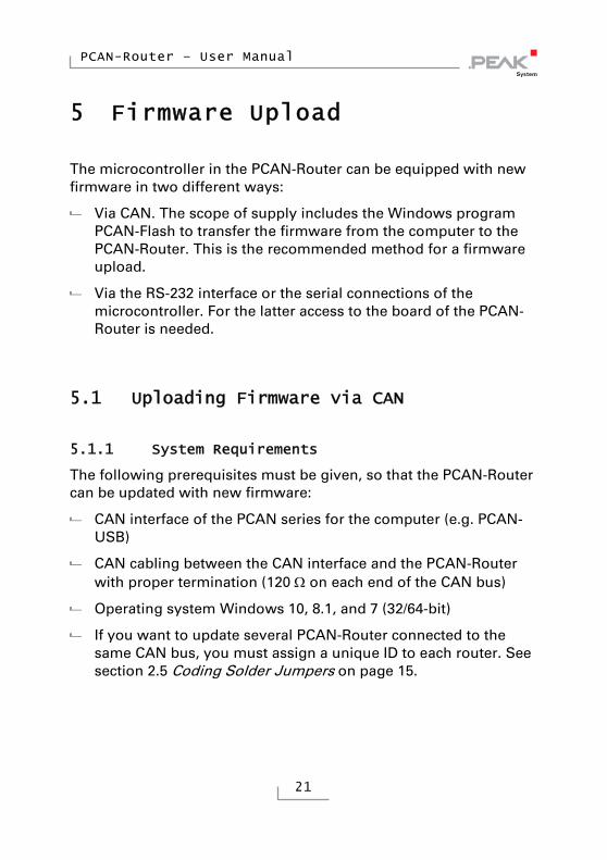
The microcontroller in the PCAN-Router can be equipped with new firmware in two different ways:
Via CAN. The scope of supply includes the Windows program PCAN-Flash to transfer the firmware from the computer to the PCAN-Router. This is the recommended method for a firmware upload.
Via the RS-232 interface or the serial connections of the microcontroller. For the latter access to the board of the PCAN-Router is needed.
5.1 Uploading Firmware via CAN
5.1.1 System Requirements
The following prerequisites must be given, so that the PCAN-Router can be updated with new firmware:
CAN interface of the PCAN series for the computer (e.g. PCAN-USB)
CAN cabling between the CAN interface and the PCAN-Router with proper termination (120 on each end of the CAN bus)
Operating system Windows 10, 8.1, and 7 (32/64-bit)
If you want to update several PCAN-Router connected to the same CAN bus, you must assign a unique ID to each router. See section 2.5 Coding Solder Jumpers on page 15.
PCAN-Router – User Manual
22
5.1.2 Preparing Hardware and Software
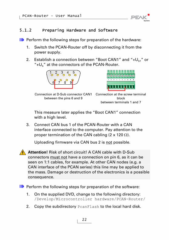
Perform the following steps for preparation of the hardware:
1. Switch the PCAN-Router off by disconnecting it from the power supply.
2. Establish a connection between “Boot CAN1” and “+Ub1” or “+Ub” at the connectors of the PCAN-Router.
Connection at D-Sub connector CAN1 between the pins 6 and 9
Connection at the screw terminal block
between terminals 1 and 7
This measure later applies the “Boot CAN1” connection with a high level.
3. Connect CAN bus 1 of the PCAN-Router with a CAN interface connected to the computer. Pay attention to the proper termination of the CAN cabling (2 x 120 ).
Uploading firmware via CAN bus 2 is not possible.
Attention! Risk of short circuit! A CAN cable with D-Sub connectors must not have a connection on pin 6, as it can be seen on 1:1 cables, for example. At other CAN nodes (e.g. a CAN interface of the PCAN series) this line may be applied to the mass. Damage or destruction of the electronics is a possible consequence.
Perform the following steps for preparation of the software:
1. On the supplied DVD, change to the following directory: /Develop/Microcontroller hardware/PCAN-Router/
2. Copy the subdirectory PcanFlash to the local hard disk.

PCAN-Router – User Manual
23
The contained Windows software that copies the Firmware via CAN (PcanFlash.exe) can only be started from a data carrier that is writable.
5.1.3 Uploading the Firmware
The process of uploading new firmware to the PCAN-Router is as follows:
1. Ensure that a connection is established between the “Boot CAN1” and “+Ub1” or “+Ub” connections of the PCAN-Router (details: see above).
2. Switch the PCAN-Router on by applying voltage supply.
Due to the High level at the “Boot CAN” connection, the PCAN-Router starts the CAN bootloader. This can be identified by two orange LEDs. Starting with version 2 of the CAN bootloader (standard on IPEH-002210(-P) from ser. no. 00300 and all IPEH-002211) the LED “CAN1” blinks.
3. Run the program PcanFlash.exe under Windows from the local hard drive.
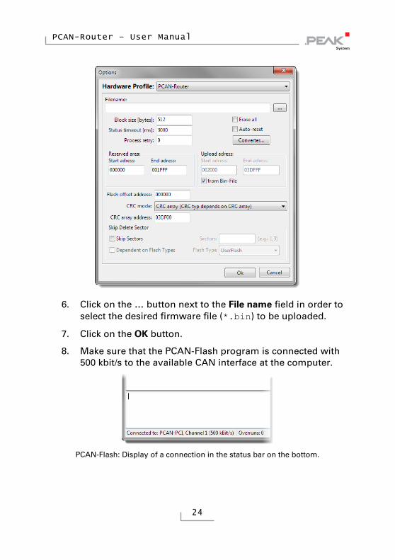
4. Click on the (Options) button in order to call up the dialog box.
5. From the Hardware Profile dropdown list, select the PCAN-Router entry.
PCAN-Router – User Manual
24
6. Click on the … button next to the File name field in order to select the desired firmware file (*.bin) to be uploaded.
7. Click on the OK button.
8. Make sure that the PCAN-Flash program is connected with 500 kbit/s to the available CAN interface at the computer.
PCAN-Flash: Display of a connection in the status bar on the bottom.
PCAN-Router – User Manual
25
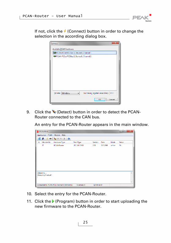
If not, click the (Connect) button in order to change the selection in the according dialog box.
9. Click the (Detect) button in order to detect the PCAN-Router connected to the CAN bus.
An entry for the PCAN-Router appears in the main window.
10. Select the entry for the PCAN-Router.
11. Click the (Program) button in order to start uploading the new firmware to the PCAN-Router.

PCAN-Router – User Manual
26
Observe the status indication at the bottom of the window. The process was successful if the last message to appear is “Flashing of module(s) finished!”.
12. Disconnect the power supply from the PCAN-Router.
13. Disconnect “Boot CAN1” from “+Ub1” or “+Ub”.
You can now use the PCAN-Router with the new firmware.
5.2 Uploading Firmware via the Serial Connections
This section shows how to activate the microcontroller’s boot-loader. The actual upload process depends on the upload software used which is supplied by a third party and is not described here.
Important note: When uploading a firmware via the RS-232 interface, the CAN bootloader may be overwritten. Afterwards a firmware upload via CAN is not possible anymore.
Do the following to activate the microcontroller's bootloader:
1. Switch the PCAN-Router off by disconnecting it from the power supply.
2. Open the casing of the PCAN-Router by removing the screws in order to gain access to the board.
3. Establish a connection on the J4 connector panel between pin 4 (\Boot_ser) and pin 5 (GND).
IPEH-2210(-P) up to ser. no. 00458 IPEH-2210(-P) from ser. no. 00459
and all IPEH-2211

PCAN-Router – User Manual
27
4. Establish a serial connection to the computer or program adapter. This is carried out either via the RS-232 interface (IPEH-002210-P only) or via the serial ports of the microcon-troller (TTL levels). See also chapter 2 Connectors and Coding Solder Jumpers on page 8.
5. Switch the PCAN-Router on by applying voltage supply.
Due to the Low level on port P0.14 of the microcontroller, the PCAN-Router starts the bootloader for serial copying. Neither LED is illuminated.
PCAN-Router – User Manual
28
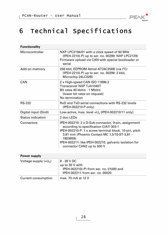
6 Technical Specifications
Functionality
Microcontroller NXP LPC2194/01 with a clock speed of 60 MHz (IPEH-2210(-P) up to ser. no. 00299: NXP LPC2129)
Firmware upload via CAN with special bootloader or serial
Add-on memory 256 kbit, EEPROM Atmel AT24C256B (via I2C) (IPEH-2210(-P) up to ser. no. 00299: 2 kbit, Microchip 24LC02B)
CAN 2 x High-speed CAN ISO 11898-2 Transceiver NXP TJA1040T Bit rates 40 kbit/s - 1 Mbit/s
(lower bit rates on request) No termination
RS-232 RxD and TxD serial connections with RS-232 levels (IPEH-002210-P only)
Digital input (Din0) Low-active, max. level +Ub (IPEH-002210/11 only)
Status indication 2 duo LEDs
Connectors IPEH-002210: 2 x D-Sub connector, 9-pin, assignment according to specification CiA® 303-1
IPEH-002210-P: 1 x screw terminal block, 10-pin, pitch 3.81 mm (Phoenix Contact MC 1,5/10-ST-3,81 - 1803659)
IPEH-002211: like IPEH-002210, galvanic isolation for connector CAN2 up to 500 V
Power supply
Voltage supply (+Ub) 8 - 26 V DC up to 30 V with
IPEH-002210(-P) from ser. no. 01000 and IPEH-002211 from ser. no. 00020
Current consumption max. 70 mA at 12 V
PCAN-Router – User Manual
29
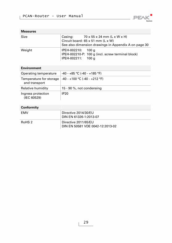
Measures
Size Casing: 70 x 55 x 24 mm (L x W x H) Circuit board: 65 x 51 mm (L x W) See also dimension drawings in Appendix A on page 30
Weight IPEH-002210: 100 g IPEH-002210-P: 100 g (incl. screw terminal block) IPEH-002211: 100 g
Environment
Operating temperature -40 - +85 °C (-40 - +185 °F)
Temperature for storage and transport
-40 - +100 °C (-40 - +212 °F)
Relative humidity 15 - 90 %, not condensing
Ingress protection (IEC 60529)
IP20
Conformity
EMV Directive 2014/30/EU DIN EN 61326-1:2013-07
RoHS 2 Directive 2011/65/EU DIN EN 50581 VDE 0042-12:2013-02

PCAN-Router – User Manual
30
Appendix A CE Certificate

PCAN-Router – User Manual
31
Appendix B Dimension Drawings
The figures do not show the original size.

PCAN-Router – User Manual
32
Appendix C Port Assignment of the Microcontroller
The following table lists the used inputs and outputs (ports) of the LPC2129 and LPC2194/01 microcontroller (μC) and their function in the PCAN-Router. It is meant as supplemental information. The converter's functionality is implemented by the supplied library.
Get additional information about the LPC2129 and LPC2194/01 microcontrollers on the homepage of NXP (www.nxp.com).
Port I/O μC function Signal Active (μC)
Function/connection6
P0.0 O TxD UART0 TxD0 Serial communication, Transmit, J4:2 or STB:10 (RS-232 levels)
P0.1 I RxD UART0 RxD0 Serial communication, Receive, J4:1 or STB:9 (RS-232 levels)
P0.2 I, O SCL SCL
P0.3 I, O SDA SDA
I2C bus to the EEPROM Microchip 24LC02B or Atmel AT24C256B7
P0.4 I Port pin ID0 High
P0.5 I Port pin ID1 High
P0.6 I Port pin ID2 High
P0.7 I Port pin ID3 High
Coding solder jumpers on board (ID 0 - 3), bridged = Low
P0.8 O TxD UART1
P0.9 I RxD UART1
P0.10 O Port pin
6 CAN1/2:n Pin n of the respective D-Sub connector
STB:n Terminal n on the screw terminal block J4/5:n Pin n of the respective connector panel on the board
7 PCAN-Router IPEH-002210(-P) from serial number 00300 and all IPEH-002211
PCAN-Router – User Manual
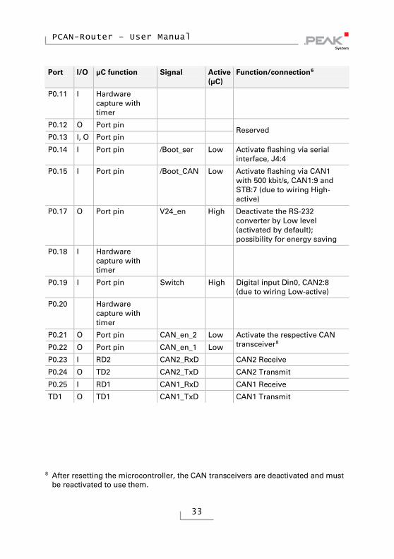
33
Port I/O μC function Signal Active (μC)
Function/connection6
P0.11 I Hardware capture with timer
P0.12 O Port pin
P0.13 I, O Port pin Reserved
P0.14 I Port pin /Boot_ser Low Activate flashing via serial interface, J4:4
P0.15 I Port pin /Boot_CAN Low Activate flashing via CAN1 with 500 kbit/s, CAN1:9 and STB:7 (due to wiring High-active)
P0.17 O Port pin V24_en High Deactivate the RS-232 converter by Low level (activated by default); possibility for energy saving
P0.18 I Hardware capture with timer
P0.19 I Port pin Switch High Digital input Din0, CAN2:8 (due to wiring Low-active)
P0.20 Hardware capture with timer
P0.21 O Port pin CAN_en_2 Low
P0.22 O Port pin CAN_en_1 Low
Activate the respective CAN transceiver8
P0.23 I RD2 CAN2_RxD CAN2 Receive
P0.24 O TD2 CAN2_TxD CAN2 Transmit
P0.25 I RD1 CAN1_RxD CAN1 Receive
TD1 O TD1 CAN1_TxD CAN1 Transmit
8 After resetting the microcontroller, the CAN transceivers are deactivated and must
be reactivated to use them.
PCAN-Router – User Manual
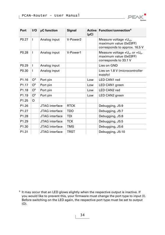
34
Port I/O μC function Signal Active (μC)
Function/connection6
P0.27 I Analog input V-Power2 Measure voltage +Ub2, maximum value (0x03FF) corresponds to approx. 16.5 V
P0.28 I Analog input V-Power1 Measure voltage +Ub1 or +Ub, maximum value (0x03FF) corresponds to 33.1 V
P0.29 I Analog input Lies on GND
P0.30 I Analog input Lies on 1.8 V (microcontroller supply)
P1.16 O9 Port pin Low LED CAN1 red
P1.17 O9 Port pin Low LED CAN1 green
P1.18 O9 Port pin Low LED CAN2 red
P1.19 O9 Port pin Low LED CAN2 green
P1.25 O
P1.26 JTAG interface RTCK Debugging, J5:9
P1.27 JTAG interface TDO Debugging, J5:7
P1.28 JTAG interface TDI Debugging, J5:8
P1.29 JTAG interface TCK Debugging, J5:5
P1.30 JTAG interface TMS Debugging, J5:6
P1.31 JTAG interface TRST Debugging, J5:10
9 It may occur that an LED glows slightly when the respective output is inactive. If
you would like to prevent this, your firmware must change the port type to input (I). Before switching on the LED again, the respective port type must be set to output (O).