pc software for x-sel - electric actuator industrial … software for x-sel operation manual st...
TRANSCRIPT

PC Software for X-SEL
Operation Manual 1st Edition
IAI America Inc.


Support Models
Various data file extensions Model Name Program
(Individually) Program(Batch) Position Parameter Symbol
Global data
Support Started Version
X-SEL-J/K xpg xpa Xpt xpm xsm xgd V1.0.0.0 X-SEL-JX/KX spg spa spt spm ssm sgd V2.0.0.0 X-SEL-P/Q x2pg x2pa x2pt x2pm x2sm x2gd V3.0.0.0
TT tpg tpa tpt tpm tsm tgd V4.0.0.0 X-SEL-PX/QX s2pg s2pa s2pt s2pm s2sm s2gd V5.0.0.0
SSEL sspg sspa sspt sspm sssm ssgd V6.0.0.0 ASEL aspg aspa aspt aspm assm asgd V7.0.0.0 PSEL pspg pspa pspt pspm pssm psgd V7.0.0.0

Software License Agreement
Thank you for purchasing the PC software for IAI’s X-SEL controller. This software is provided strictly with your consent to this agreement. Before opening the software package,
please read this Agreement. If you do not agree to any of the terms and conditions specified herein, please return the unopened software to IAI, and we will refund you the purchase price. (Regardless of the reason, opening the software package will be regarded as your acknowledgement of consenting to this Agreement.)
IAI Corporation (hereinafter referred to as “IAI”) shall grant to the user (hereinafter referred to as “the User”), and
the User shall accept, a non-transferable, non-exclusive right to use the software program supplied with this Agreement (hereinafter referred to as “the Licensed Software”), based on the following terms and conditions. 1. Term of the Agreement
This Agreement shall take effect the moment the User opens the Licensed Software and remain effective until the User submits a termination request to IAI in writing or the Agreement is otherwise terminated pursuant to the provision of Section 5.
2. Right to Use the Licensed Software The User may use the Licensed Software that has been licensed to the User under this Agreement, on a single computer system (hereinafter referred to as “system”) in a machine-readable format. A separate license must be obtained in order to use the Licensed Software on a different system. The User may not assign, sublicense or transfer to a third party the right to use the Licensed Software granted under this Agreement, the software specified hereunder, or any other item relating thereto, without obtaining a prior written consent from IAI. Unless otherwise specified expressly in this Agreement, the User is not given any right to print or reproduce the Licensed Software in whole or in part.
3. Duplication of the Licensed Software The User may not duplicate any part of the documentation provided by IAI in accordance with this Agreement. Creation of a duplicate of the Licensed Software provided by IAI in a machine-readable format shall be permitted solely for the purpose of backing up the software.
4. Protection of the Licensed Software The User may not provide the Licensed Software to any individual other than the employees of the User or IAI, without obtaining a prior written consent from IAI.
5. Termination of the Agreement In the event of breach by the User of any of the terms and conditions hereunder, or upon discovery of a material cause that makes continuation of this Agreement impossible, IAI may immediately terminate this Agreement without serving any prior notice to the User. If the Agreement is terminated for the above reason, the User must destroy the Licensed Software received from IAI and all duplicates thereof within ten (10) days after the lapse of the Agreement and send a confirmation of such destruction to IAI.
6. Scope of Protection IAI reserves the right to change any and all specifications relating to the Licensed Software without prior notice. IAI shall make no warranty whatsoever with respect to the Licensed Software. The User agrees not to claim compensation for damage from IAI for any loss suffered by the User as a result of installing the Licensed Software in the User’s system.
A Word of Caution
[1] This software is copyrighted by IAI Corporation (IAI). [2] This software and the accompanying manual may not be used or duplicated in part or in whole without a
permission of IAI. [3] A separate software program must be purchased for each PC in which it is run. [4] The software and the manual can only be used under the terms and conditions of the license agreement. [5] IAI cannot assume responsibility for any damage or loss resulting from the use of this software or the manual. [6] Please note that the version or edition number printed on the face of this manual does not correspond to the
software version number. [7] The content of this manual is subject to change without notice. [8] This software runs on Windows shown below. This manual has been written on the assumption that the user
already has a basic understanding of Windows operations. (However, this software does not contain Windows.)
Port used Type Operable Windows
RS-232C IX-101-X-MW-J IX101-X-MW IX-101-XA-MW
Windows 98, Windows Me, Windows 2000, Windows XP *1
USB IX-101-X-USB IX-101-X-USBMW
Windows 98SE、Windows Me、Windows 2000、Windows XP
*1: Supported by software version 7.0.0.0 or later. Microsoft, MS, MS-DOS, Windows, Windows 3.1, Windows 95, Windows 98, Windows NT, Windows 2000, Windows Me and Windows XP are registered trademarks of Microsoft Corporation. Copyright© 2006 Sept. IAI Corporation. All rights reserved.

Table of Contents
1. Before You Begin .............................................................................................................................................. 1
1.1 Items Supplied with This Software (Product Components)................................................................... 1
1.2 What You Will Need (System Requirements)....................................................................................... 2
1.3 Installing the Software.......................................................................................................................... 3
1.3.1 How to Install the PC Interface Software for X-SEL.............................................................................. 3 1.3.2 How to Install the USB Conversion Adapter Driver Software................................................................ 6
1.4 Connection to Controller..................................................................................................................... 16
1.5 Starting the Software.......................................................................................................................... 24
2. How to Save Data ........................................................................................................................................... 27
2.1 Factory Setting – When a Backup Battery Is Used (When the X-SEL controller is shipped) .............. 27
2.2 When a Backup Battery Is Not Used (Table Top Actuator [TT], SSEL, ASEL, PSEL) ........................ 28
2.3 Notes.................................................................................................................................................. 29
3. Menu Window.................................................................................................................................................. 30
3.1 Explanation of the Menu..................................................................................................................... 30
3.1.1 Online Screen .................................................................................................................................... 30 3.1.2 Offline Screen .................................................................................................................................... 34
3.2 Explanation of the Commands ........................................................................................................... 35
3.3 Explanation of the Toolbar ................................................................................................................. 42
3.4 Tree View........................................................................................................................................... 44
4. Program Edit Window...................................................................................................................................... 46
4.1 Explanation of the Items Displayed in the Program Edit Window ....................................................... 46
4.2 Saving a Program and Closing the Edit Window ................................................................................ 53
4.3 Saving All Programs to a File ............................................................................................................. 54
4.4 Running the Program ......................................................................................................................... 56
5. Copying/Moving/Clearing a Program............................................................................................................... 57
5.1 Program Copy/Move Window............................................................................................................. 57
5.2 Program Clear Window ...................................................................................................................... 58
6. Position Data Edit Window .............................................................................................................................. 59
6.1 Explanation of the Items Displayed in the Position Data Edit Window................................................ 59
6.2 Saving Position Data and Closing the Edit Window............................................................................ 70
7. Copying/Moving/Clearing Position Data .......................................................................................................... 71
7.1 Copying/Moving Position Data ........................................................................................................... 71
7.2 Clearing Position Data ....................................................................................................................... 72
8. Parameter Edit Window................................................................................................................................... 73
8.1 Explanation of the Parameter Edit Window ........................................................................................ 73
8.2 Saving Parameter Data and Closing the Edit Window........................................................................ 74
8.3 Transferring a Parameter File ............................................................................................................ 77
8.3.1 Selecting Categories of Parameters to Be Transferred ...................................................................... 77 8.3.2 Default Specifications......................................................................................................................... 80
8.4 How to Initialize SSEL/ASEL/PSEL Parameters (at the time of shipment) ......................................... 81
9. Symbol Edit Window ....................................................................................................................................... 83
9.1 About Symbols ................................................................................................................................... 83
9.2 Explanation of the Symbol Edit Window............................................................................................. 84
9.3 Saving Symbol Data and Closing the Edit Window ............................................................................ 86
10. Coordinate System Definition Data Edit Window............................................................................................. 87
10.1 Explanation of Coordinate System Definition data Edit Window......................................................... 87
10.2 Work Coordinate System ................................................................................................................... 89
10.3 Tool Coordinate System..................................................................................................................... 93
10.4 Simple Interference Check Zone........................................................................................................ 97
10.5 Coordinate System Definition Data Clear Window ........................................................................... 100
10.6 Printing of Coordinate System Definition Data ................................................................................. 101
11. Monitor .......................................................................................................................................................... 102
12. How to Reset an Absolute Encoder............................................................................................................... 113
12.1 Orthogonal axis ................................................................................................................................ 113
12.2 Scara Axis........................................................................................................................................ 115
12.2.1 Absolute Reset Preparation............................................................................................................ 115 12.2.2 Starting the Absolute Reset Menu .................................................................................................. 116 12.2.3 Absolute Reset Procedure for Arm 1 or 2 ....................................................................................... 117 12.2.4 Absolute Reset Procedure for Rotation Axis + Vertical Axis ........................................................... 125
13. Supplemental Information on Controller Menu Items..................................................................................... 135
13.1 Software Reset................................................................................................................................. 135
13.2 Reset Error....................................................................................................................................... 135
13.3. Drive-source Recovery Request and Operation-pause Reset Request............................................ 136

13.3.1 In the cases of Controllers Other Than SSEL, ASEL or PSEL Controllers...................................... 136 13.3.2 In the cases of SSEL, ASEL or PSEL Controllers........................................................................... 137
13.4 SEL Global Data Backup.................................................................................................................. 138
13.5 Control Constant Table Management Information............................................................................ 140
13.6 Execution Stop of Positioner Mode of SSEL, ASEL or PSEL Controller........................................... 141
13.7 Getting Positioner Mode Information from SSEL, ASEL or PSEL Controller .................................... 142
13.8 Positioner Mode Management Information for SSEL, ASEL or PSEL Controller .............................. 143
14. Tool ............................................................................................................................................................... 144
Appendix Parameter Recovery Method for X-SEL-P/Q and PX/QX Controllers.................................................................... 146
Error Level Control................................................................................................................................................ 153
X-SEL PC Software Error Table............................................................................................................................ 154


1
1. Before You Begin 1.1 Items Supplied with This Software (Product Components)
Please check to make sure that the following items are included in your software package. [1] Operation manual (1) [2] CD-ROM containing the software (1) [3] External connection cables
External connection cables vary depending on the PC interface software type. The types and external connection cables are shown in the table below.
Type External Connection Cable
IA-101-X-MW-J RS232C cable (CB-ST-E1MW050-EB): 1 cable Conversion cable (CB-SEL-SJ002): 1 cable
IA-101-X-MW RS232C cable (CB-ST-E1MW050-EB): 1 cable
Con
nect
ion
Con
figur
atio
n
When an NEC computer is used, some models may require an adapter separately for the RS232C cable.
Type External Connection Cable IA-101-X-MW Cable Conforming to Safety Category 4 (CB-ST-A1MW050-EB): 1 cable
Con
nect
ion
Con
figur
atio
n
Type External Connection Cable IA-101-X-USB USB cable (CB-SEL-USB010): 1 cable
Dummy plug (DP-3)
Con
nect
ion
Con
figur
atio
n
Compatible controller XSEL-P, PX
RS232C cable CB-ST-E1MW050-EB Conversion cable:
CB-SEL-SJ002
Compatible controller SSEL
Cable corresponding to safety category CB-ST-A1MW050-EB
Compatible controller XSEL-Q, QX
Dummy plug DP-3
USB cable CB-SEL-USB010
Compatible controller SSEL

2
Type External Connection Cable
IA-101-X-USBMW USB conversion adapter (IA-CV-USB): 1 unit USB cable (CB-SEL-USB010): 1 piece Dummy plug (DP-3)
Con
nect
ion
Con
figur
atio
n
1.2 What You Will Need (System Requirements)
The following PC and peripherals will be necessary to run this software program. [1] PC and compatible keyboard
A PC *1 running Windows and a compatible keyboard. (*1: Personal computer. Abbreviated as “PC” throughout this manual.)
[2] Memory Enough memory to run Windows.
[3] Display: VGA or higher-resolution monitor (XGA or better is recommended)
[4] Mouse or other pointing device and mouse driver The mouse or other pointing device with which you can operate this software comfortably, and an applicable driver.
[5] Windows Windows 95, Windows 98, Windows NT, Windows 2000, Windows Me or Windows XP.
[6] CD-ROM drive unit [7] Hard disk
The hard disk should have 5 MB or more of free disk space. (The software is run from the hard disk.) [8] Serial port: Type IA-101-X-MW-J, IA-101-X-MW or IA-101-XA-MW
An RS232C serial port. (Only a 9-pin port is supported.) [9] USB port: Type IA-101-X-USB or IA-101-X-USBMW [10] Printer
A printer compatible with the PC.
USB conversion adapter
USB cable CB-SEL-USB010
RS232C cable CB-ST-E1MW050-EB
Compatible controller XSEL-P, PX

3
1.3 Installing the Software
This software is run from the hard disk. This section explains how to install the software. 1.3.1 How to Install the PC Interface Software for X-SEL When the PC interface software of software version 6.0.0.0 or earlier is preinstalled, uninstall it before installing the PC interface software for X-SEL. [1] Insert the CD-ROM containing this software into your CD-ROM drive. [2] The installed data selection screen (Fig. 1.1) will be displayed.
Click the data to install.
Fig. 1.1 Installed Data Selection Screen (The displayed screen may vary depending on the version, data in the CD or other factor.)
[3] The screen will change to the installation screen for PC interface software for X-SEL.
Click Next >.
Fig. 1.2 Installation Screen
4
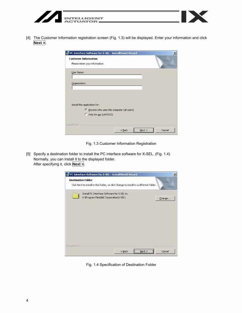
[4] The Customer Information registration screen (Fig. 1.3) will be displayed. Enter your information and click
Next >.
Fig. 1.3 Customer Information Registration [5] Specify a destination folder to install the PC interface software for X-SEL. (Fig. 1.4)
Normally, you can install it to the displayed folder. After specifying it, click Next >.
Fig. 1.4 Specification of Destination Folder

5
[6] The wizard is ready to begin installation. Clicking Install will begin actual installation.
Fig. 1.5 Installation Preparation The screen shown in Fig. 1.6 will be displayed during installation.
Fig. 1.6 Installation Progress
6
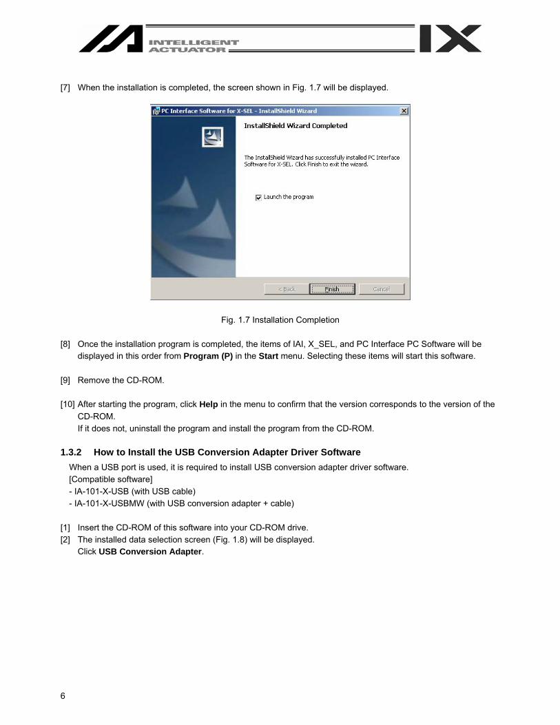
[7] When the installation is completed, the screen shown in Fig. 1.7 will be displayed.
Fig. 1.7 Installation Completion [8] Once the installation program is completed, the items of IAI, X_SEL, and PC Interface PC Software will be
displayed in this order from Program (P) in the Start menu. Selecting these items will start this software. [9] Remove the CD-ROM. [10] After starting the program, click Help in the menu to confirm that the version corresponds to the version of the
CD-ROM. If it does not, uninstall the program and install the program from the CD-ROM.
1.3.2 How to Install the USB Conversion Adapter Driver Software
When a USB port is used, it is required to install USB conversion adapter driver software. [Compatible software] - IA-101-X-USB (with USB cable) - IA-101-X-USBMW (with USB conversion adapter + cable)
[1] Insert the CD-ROM of this software into your CD-ROM drive. [2] The installed data selection screen (Fig. 1.8) will be displayed.
Click USB Conversion Adapter.

7
Fig. 1.8 Installed Data Selection Screen (The displayed screen may vary depending on the version, data in the CD or other factor.)
[3] You are prompted to set the folder of the copy destination. If you use the displayed folder as it is, click Copy. To
change it, enter it manually or click Browse to set the folder of the copy destination. On the browse for folder screen (Fig. 1.10), click the folder of the copy destination to select it and then click OK. Once you have clicked OK, the browse for folder screen (Fig. 1.10) will disappear and the selected folder path will be displayed on the screen to specify the folder of the copy destination (Fig. 1.9).
Fig. 1.9 Screen to Specify Folder of Copy Destination
Fig. 1.10 Browse for Folder Screen

8
[4] When the folder of IAI USB (copy data) already exists in the copy destination, you are prompted to overwrite it.
Click OK to overwrite it, or click Cancel to stop copying.
Fig. 1.11 Overwrite Confirmation Screen [5] The complete screen (Fig. 1.12) will be displayed.
Fig. 1.12 Complete Screen [6] Once the complete screen (Fig. 12) has been displayed, click OK. The complete screen (Fig. 1.12) will
disappear. Then, click Cancel on the screen to specify the folder of the copy destination (Fig. 1.9). The screen to specify the folder of the copy destination will disappear. Finally, click Exit on the data selection screen (Fig. 1.8). The data selection screen (Fig. 1.8) will disappear.
[7] Remove the CD-ROM. [8] Then, insert the USB conversion adapter (IA-CV-USB) into the USB port of your PC.
In the case of the SSEL/ASEL/PSEL controller or TT (table top actuator), connect the PC and SSEL/ASEL/PSEL controller or TT with the attached USB cable.

9
[9] Windows will open the Welcome to the Found New Hardware Wizard.
Click Next >.
Fig. 1.13 Welcome to Found New Hardware Wizard Screen [10] The Install Hardware Device Drivers screen will open.
Select Search for a suitable driver for my device [recommended]. Click Next >.
Fig. 1.14 Install Hardware Device Drivers Screen
10
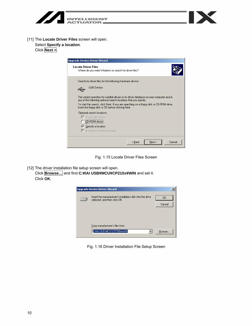
[11] The Locate Driver Files screen will open.
Select Specify a location. Click Next >.
Fig. 1.15 Locate Driver Files Screen [12] The driver installation file setup screen will open.
Click Browse… and find C:¥IAI USB¥MCU¥CP210x¥WIN and set it. Click OK.
Fig. 1.16 Driver Installation File Setup Screen

11
[13] The Driver Files Search Results screen will open.
Click Next >. The installation of the IAI USB Composite Device driver will start.
Fig. 1.17 Driver Files Search Results Screen [14] When the IAI USB Composite Device driver installation finish is displayed, the installation of the driver is
completed. Click Finish.
Fig. 1.18 IAI USB Composite Device Installation Finish Screen
12
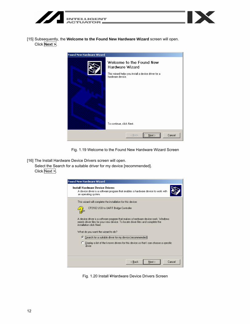
[15] Subsequently, the Welcome to the Found New Hardware Wizard screen will open.
Click Next >.
Fig. 1.19 Welcome to the Found New Hardware Wizard Screen [16] The Install Hardware Device Drivers screen will open.
Select the Search for a suitable driver for my device [recommended]. Click Next >.
Fig. 1.20 Install ¥Hardware Device Drivers Screen
13
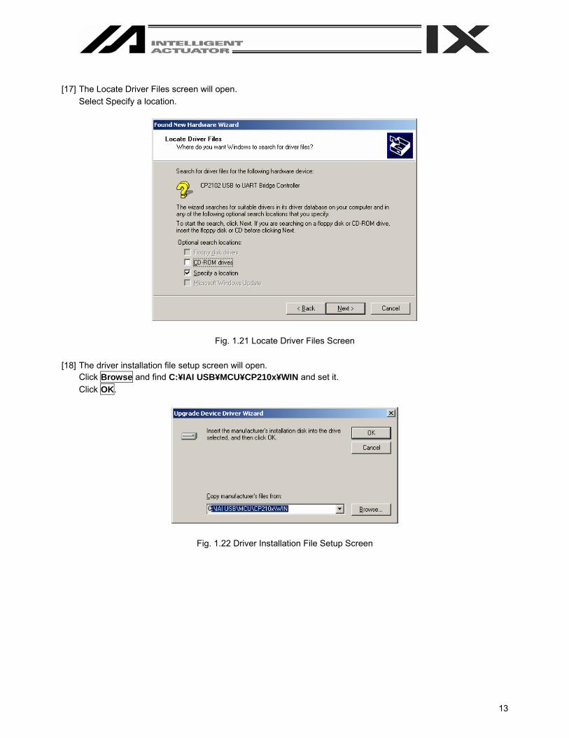
[17] The Locate Driver Files screen will open.
Select Specify a location.
Fig. 1.21 Locate Driver Files Screen [18] The driver installation file setup screen will open.
Click Browse and find C:¥IAI USB¥MCU¥CP210x¥WIN and set it. Click OK.
Fig. 1.22 Driver Installation File Setup Screen

14
[19] The Driver Files Search Results screen will open.
Click Next >. The installation of the IAI USB to UART Bridge Controller driver will start.
Fig. 1.23 Driver File Search Results Screen [20] When the IAI USB to UART Bridge Controller driver installation finish is displayed, the driver installation is
completed. Click Finish.
Fig. 1.24 IAI USB to UART Bridge Controller Installation Finish Screen
15
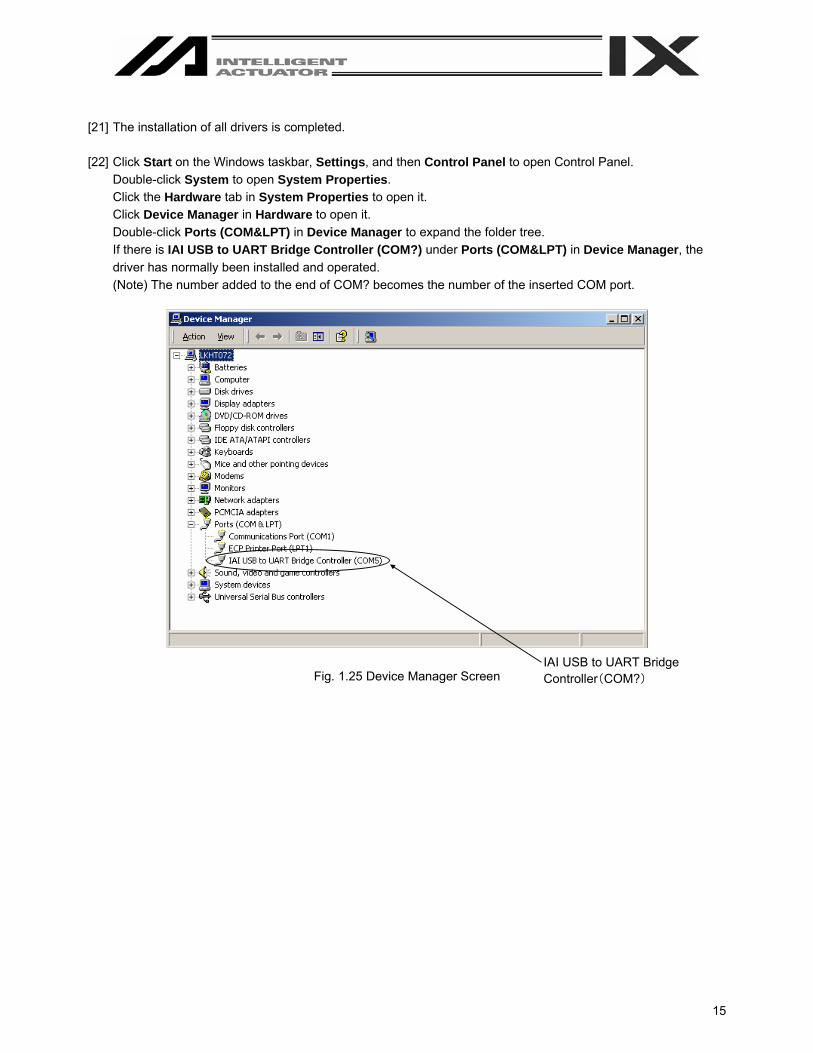
[21] The installation of all drivers is completed. [22] Click Start on the Windows taskbar, Settings, and then Control Panel to open Control Panel.
Double-click System to open System Properties. Click the Hardware tab in System Properties to open it. Click Device Manager in Hardware to open it. Double-click Ports (COM&LPT) in Device Manager to expand the folder tree. If there is IAI USB to UART Bridge Controller (COM?) under Ports (COM&LPT) in Device Manager, the driver has normally been installed and operated. (Note) The number added to the end of COM? becomes the number of the inserted COM port.
Fig. 1.25 Device Manager Screen IAI USB to UART Bridge Controller(COM?)

16
1.4 Connection to Controller
Fig. 1.23 X-SEL-K (J) Type Controller
1-axis
2-axis
Mode Switch
PC

17
Fig. 1.24 X-SEL-P (Q) Type Controller
Caution: Set the teaching pendant type selector switch to the right.
Mode Switch
Teaching Pendant Type Selector Switch
Emergency Stop Switch
Enable Switch
2-axis
1-axis
PC

18
Fig. 1.25 Table Top Actuator (TT)
Mode Switch
PC

19
Fig. 1.26 X-SEL-KX (JX) Type Controller
Mode Switch
PC
SCARA
20
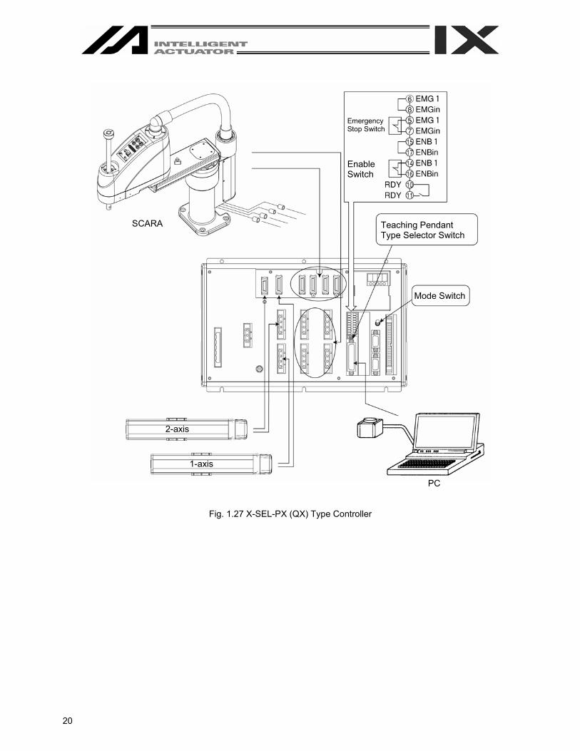
Fig. 1.27 X-SEL-PX (QX) Type Controller
Mode Switch
PC
SCARA Teaching Pendant Type Selector Switch
Emergency Stop Switch
Enable Switch
2-axis
1-axis
21
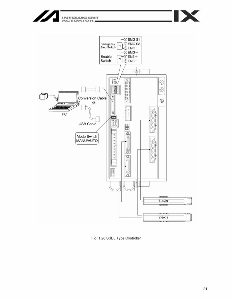
Fig. 1.28 SSEL Type Controller
PC
Emergency Stop Switch
Enable Switch
2-axis
1-axis
Conversion Cable or
USB Cable
Mode Switch MANU/AUTO

22
Fig. 1.29 ASEL Type Controller
Host System
Conversion Cable Panel Unit
Emergency Stop Switch
Enable Switch
24V DC, 0V Power Supply: 24V

23
Fig. 1.30 PSEL Type Controller
Host System
Conversion Cable Panel Unit
Emergency Stop Switch
Enable Switch
24V DC, 0V Power Supply: 24V

24
1.5 Starting the Software [1] Turn off the power to the controller and PC, and connect the controller to the PC using the standard RS232C
cable or USB cable that comes with the software. Set the mode switch on the controller to the MANU side.
- When this software is started, the “safety velocity” mode is enabled (enable the safety velocity limit). In this
mode, in the case of orthogonal axis, the maximum velocity is limited to 250 mm/sec or below in programs started from the PC software. In the case of SCARA axes, the maximum velocity during CP operation is limited to 250 mm/sec or below (PTP operation: 3% or below). To operate programs according to their programmed velocity commands, the safety velocity mode must be disabled. Refer to 3.3, “Explanation of the Toolbar,” for how to enable/disable the safety velocity mode.
[2] Turn on the power to the controller and PC, and start Windows. [3] Start this software.
When the application is started, the Connection Confirmation window (Fig. 1.31) will open first. In the list boxes of Port Name and Baud Rate (bps), select the communication port (*1) to which the X-SEL, TT, SSEL, ASEL, or PSEL controller is connected and an applicable baud rate (*2), and then click OK.
(*1) Only the communication ports that are available when the
application is started can be selected. (*2) “57600” and “115200” bps are supported only by the P/Q
controllers.
Fig. 1.31 Connection Confirmation Window [4] If XSEL-P/Q (application version 0.36 or later), XSEL-PX/QX (application version 0.17 or later), SSEL, ASEL, or
PSEL (application version 0.01 or later) is connected, the Two or more programs start permission/prohibition setting screen (Fig. 1.32) will be displayed. Set whether you prohibit or permit the simultaneous starting of multiple programs during the manual mode, and click the OK button. [Two or more programs start prohibition (MANU)] It prohibits the simultaneous starting of multiple programs during the manual mode. [Two or more programs start permission (MANU)] It permits the simultaneous starting of multiple programs during the manual mode.
Fig. 1.32 Two or More Programs Start Permission/Prohibition Setting Screen

25
If Don’t Show this window from next time on is checked, connection will be established with the settings at
the last connection time without displaying the screen in Fig. 1.32. To remove this check, select the checkbox In Connect, Check Setting of Two or more programs start on the Environment Setup (Online) screen (Fig. 14.2) or Environment Setup (Offline) screen (Fig. 14.1). The screen in Fig. 1.32 will be displayed at the next startup time to remove the check. For the Environment Setup (Online) screen and Environment Setup (Offline) screen, refer to “14. Tool.”
If you set Two or more programs start prohibition (MANU) when multiple programs have already started, the
warning message will be displayed. To prohibit the simultaneous starting of multiple programs, click the Yes button to stop all the programs.
Fig. 1.33 Warning Message [5] Once the controller connection is confirmed, the application will start in the offline mode. If the controller cannot
be recognized or the CANCEL button is clicked in this window, the application will start in the offline mode. (Even after the application has started in the offline mode, you can use the “Reconnect” function explained later to switch the application to the online mode.) If Don’t Show this window from next time on is selected, the software will automatically select the port name and baud rate that were in use the last time the application was closed and check the controller connection based on these settings.
26
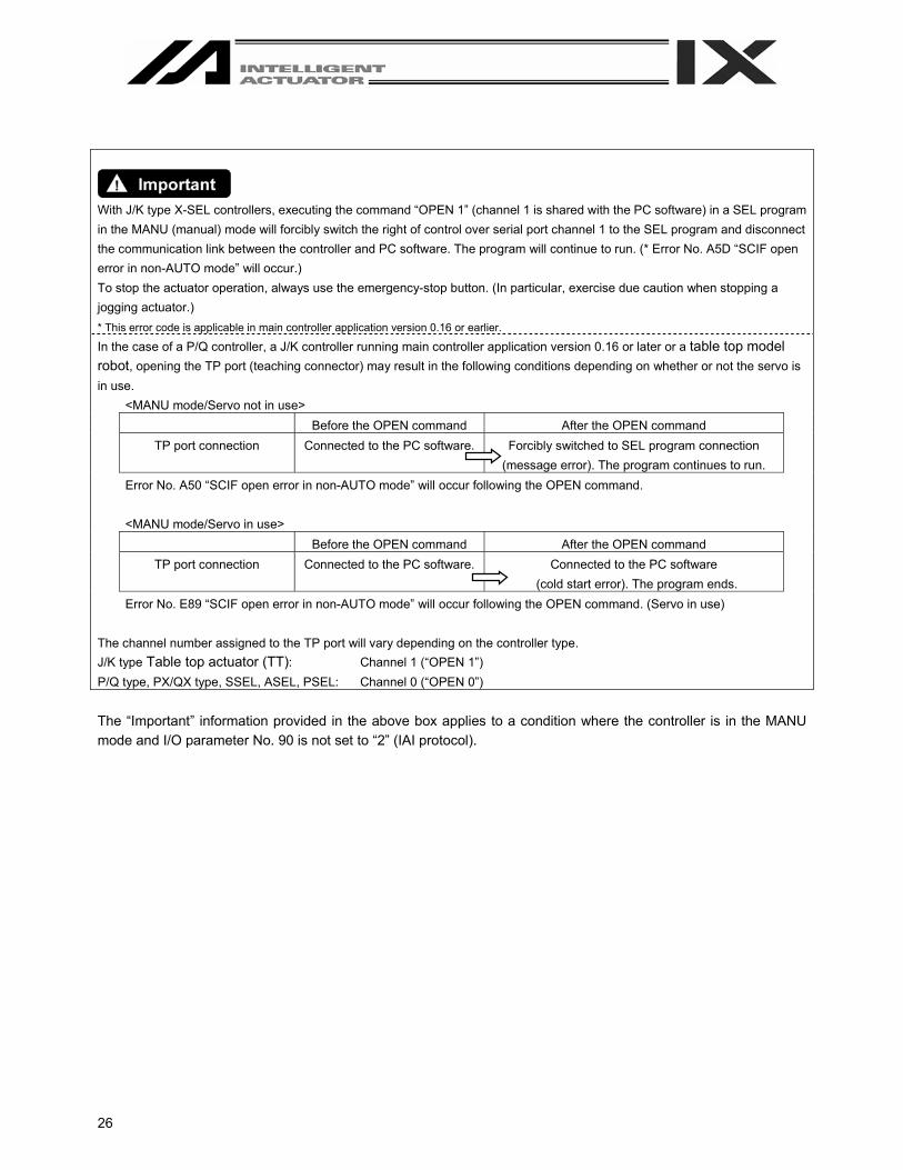
With J/K type X-SEL controllers, executing the command “OPEN 1” (channel 1 is shared with the PC software) in a SEL program in the MANU (manual) mode will forcibly switch the right of control over serial port channel 1 to the SEL program and disconnect the communication link between the controller and PC software. The program will continue to run. (* Error No. A5D “SCIF open error in non-AUTO mode” will occur.) To stop the actuator operation, always use the emergency-stop button. (In particular, exercise due caution when stopping a jogging actuator.) * This error code is applicable in main controller application version 0.16 or earlier. In the case of a P/Q controller, a J/K controller running main controller application version 0.16 or later or a table top model robot, opening the TP port (teaching connector) may result in the following conditions depending on whether or not the servo is in use.
<MANU mode/Servo not in use> Before the OPEN command After the OPEN command TP port connection Connected to the PC software. Forcibly switched to SEL program connection
(message error). The program continues to run.
Error No. A50 “SCIF open error in non-AUTO mode” will occur following the OPEN command. <MANU mode/Servo in use>
Before the OPEN command After the OPEN command TP port connection Connected to the PC software. Connected to the PC software
(cold start error). The program ends.
Error No. E89 “SCIF open error in non-AUTO mode” will occur following the OPEN command. (Servo in use) The channel number assigned to the TP port will vary depending on the controller type. J/K type Table top actuator (TT): Channel 1 (“OPEN 1”) P/Q type, PX/QX type, SSEL, ASEL, PSEL: Channel 0 (“OPEN 0”) The “Important” information provided in the above box applies to a condition where the controller is in the MANU mode and I/O parameter No. 90 is not set to “2” (IAI protocol).

27
2. How to Save Data The controller adopts a flash memory. Accordingly, some data is stored in the memory areas backed up by a
battery, while other data is stored in the flash memory areas. Also note that transferring data from the PC software or teaching pendant to the controller will only write the data
in the controller’s memory, as illustrated below, and the data will be cleared once the controller power is turned off or the controller is reset.
To save important data, always write it in the flash memory. 2.1 Factory Setting – When a Backup Battery Is Used (When the X-SEL controller is
shipped) (Other parameter No. 20 = “2” (Backup battery installed))
* Encoder parameters are stored in the EEPROM of the actuator’s encoder, not in the controller’s EEPROM. Therefore, encoder
parameters will be loaded to the controller every time the controller power is turned on or a software reset is executed.
Data edited on the PC or teaching pendant
Data retained while the power is on, and cleared after reset
Data retained after the power is turned off
Programs, parameters (content 1),
symbols
Slave card parameters (content 2)
* Encoder parameters
Positions
SEL global data (content 3), error lists
Transfer
Transfer
Transfer
Transfer
Transfer
Transfer
Transfer
Memory
Memory
Memory
Write to flash memory
Load after reset
Load after reset
Load after reset
Flash memory
EEPROM
* Encoder’s EEPROM
Memory backed upby battery
Memory backed upby battery
Flash memory
Write to flash memory

28
Programs, parameters and symbols are loaded from the flash memory after the controller is restarted.
Unless written to the flash memory, therefore, edited programs, parameters and symbols will return to the original data once the controller is restarted.
The controller always operates according to the data (excluding parameters) stored in its memory (indicated by dotted lines). Content 1: All parameters other than those specified under Content 2 Content 2: Driver card, I/O slot card, (power-supply card) parameters (X-SEL-J/K, JX/KX, TT)
I/O slot card, (power-supply card) parameters (X-SEL-P/Q, PX-QX, SSEL, ASEL, PSEL) Content 3: Flags, variables, strings and error lists
2.2 When a Backup Battery Is Not Used (Table Top Actuator [TT], SSEL, ASEL, PSEL) (Other parameter No. 20 = “0” (Backup battery not installed))
Programs, parameters and symbols are loaded from the flash memory after a restart. Unless written to the flash memory,
therefore, edited programs, parameters and symbols will return to the original data once the controller is restarted. The controller always operates according to the data (excluding parameters) stored in its memory (indicated by dotted lines).
Note: SEL global data cannot be retained when a backup battery is not installed.
Data edited on the PC or teaching pendant
Data retained while the power is on, and cleared after reset
Data retained after the power is turned off
Programs, parameters (content 1),
symbols positions
Slave card parameters (content 2)
* Encoder parameters
Transfer
Transfer
Transfer
Transfer
Transfer
Memory
Memory
Memory
Write to flash memory
Load after reset
Load after reset
Load after reset
Flash memory
EEPROM
* Encoder’s EEPROM
Memory Transfer SEL global data (content 3), error
lists

29
2.3 Notes Note on transferring data and writing it to the flash memory
Never turn off the main power while data is still being transferred or written to the flash memory. The data may be lost and the controller operation may be disabled.
Note on saving parameters to a file
Encoder parameters are saved in the EEPROM of the actuator’s encoder (unlike other parameters, they are not stored in the controller’s EEPROM). Therefore, encoder parameters are loaded from the encoder’s EEPROM to the controller after the controller power is turned on or a software reset is executed.
For this reason, saving controller parameters to a file after the controller power has been turned on (or software reset has been executed) without the actuator (encoder) connected to the controller will create a file containing invalid encoder parameters.
Note on transferring a parameter file to the controller
When a parameter file is transferred to the controller, the encoder parameters in the file will be transferred to the encoder’s EEPROM (excluding manufacture information and function information).
Therefore, transferring to the controller a parameter file that has been read from the controller after the controller was started without the actuator connected will write invalid encoder parameters to the encoder’s EEPROM. (This applies when the file is transferred to the controller to which the actuator is currently selected.)
When saving parameters to a file, therefore, do so in a condition where the controller is connected to the actuator.
30
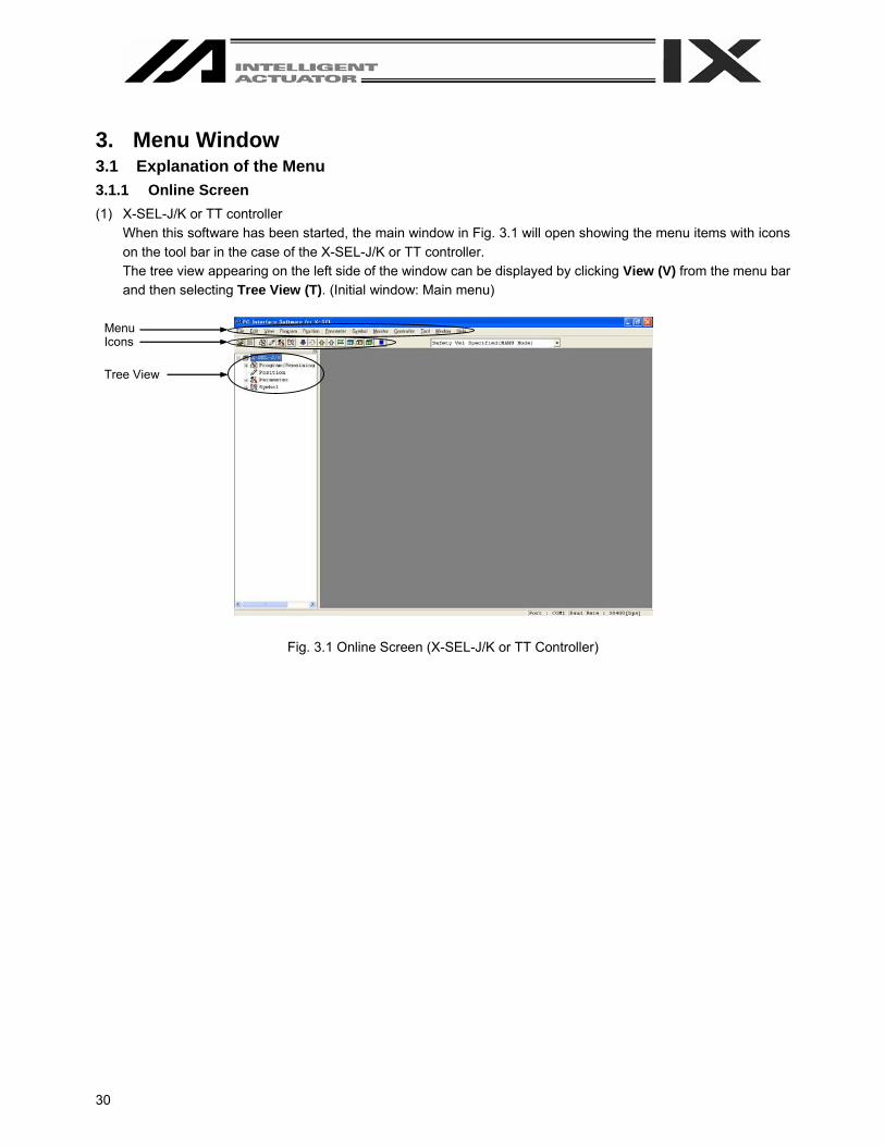
3. Menu Window 3.1 Explanation of the Menu 3.1.1 Online Screen (1) X-SEL-J/K or TT controller
When this software has been started, the main window in Fig. 3.1 will open showing the menu items with icons on the tool bar in the case of the X-SEL-J/K or TT controller. The tree view appearing on the left side of the window can be displayed by clicking View (V) from the menu bar and then selecting Tree View (T). (Initial window: Main menu)
Fig. 3.1 Online Screen (X-SEL-J/K or TT Controller)
Menu Icons
Tree View
31
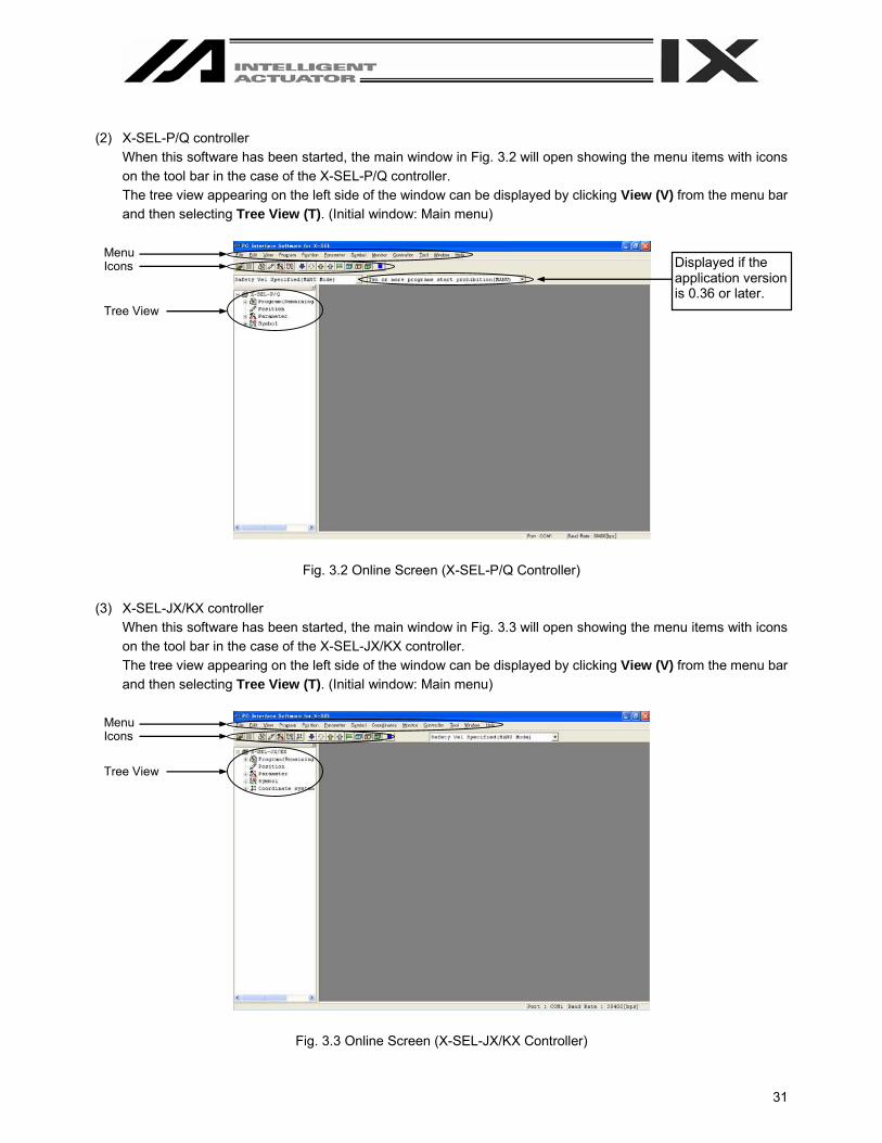
(2) X-SEL-P/Q controller
When this software has been started, the main window in Fig. 3.2 will open showing the menu items with icons on the tool bar in the case of the X-SEL-P/Q controller. The tree view appearing on the left side of the window can be displayed by clicking View (V) from the menu bar and then selecting Tree View (T). (Initial window: Main menu)
Fig. 3.2 Online Screen (X-SEL-P/Q Controller) (3) X-SEL-JX/KX controller
When this software has been started, the main window in Fig. 3.3 will open showing the menu items with icons on the tool bar in the case of the X-SEL-JX/KX controller. The tree view appearing on the left side of the window can be displayed by clicking View (V) from the menu bar and then selecting Tree View (T). (Initial window: Main menu)
Fig. 3.3 Online Screen (X-SEL-JX/KX Controller)
Menu Icons
Tree View
Displayed if the application version is 0.36 or later.
Menu Icons
Tree View
32
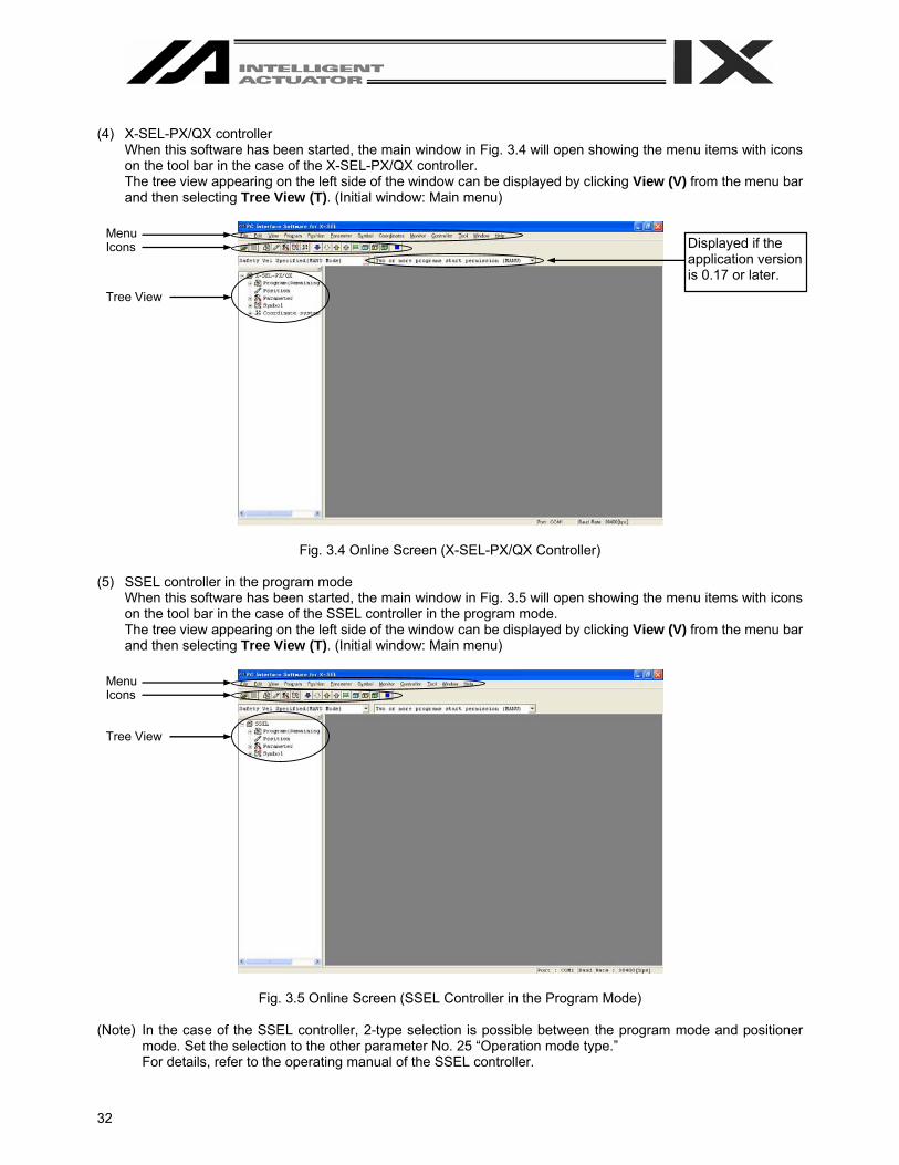
(4) X-SEL-PX/QX controller
When this software has been started, the main window in Fig. 3.4 will open showing the menu items with icons on the tool bar in the case of the X-SEL-PX/QX controller. The tree view appearing on the left side of the window can be displayed by clicking View (V) from the menu bar and then selecting Tree View (T). (Initial window: Main menu)
Fig. 3.4 Online Screen (X-SEL-PX/QX Controller) (5) SSEL controller in the program mode
When this software has been started, the main window in Fig. 3.5 will open showing the menu items with icons on the tool bar in the case of the SSEL controller in the program mode. The tree view appearing on the left side of the window can be displayed by clicking View (V) from the menu bar and then selecting Tree View (T). (Initial window: Main menu)
Fig. 3.5 Online Screen (SSEL Controller in the Program Mode) (Note) In the case of the SSEL controller, 2-type selection is possible between the program mode and positioner
mode. Set the selection to the other parameter No. 25 “Operation mode type.” For details, refer to the operating manual of the SSEL controller.
Menu Icons
Tree View
Displayed if the application version is 0.17 or later.
Menu Icons
Tree View

33
(6) SSEL controller in the positioner mode
When this software has been started, the main window in Fig. 3.6 will open showing the menu items with icons on the tool bar in the case of the SSEL controller in the positioner mode. The tree view appearing on the left side of the window can be displayed by clicking View (V) from the menu bar and then selecting Tree View (T). (Initial window: Main menu)
Fig. 3.6 Online Screen (SSEL Controller in the Positioner Mode)
However, “program edit” or “symbol edit” using the menu or tool bar will become unavailable. Icons will also become faint-colored. Two or more programs start prohibition will not be displayed, either.
(7) ASEL controller
When this software has been started, the main window in Fig. 3.7 will open showing the menu items with icons on the tool bar in the case of the ASEL controller. The tree view appearing on the left side of the window can be displayed by clicking View (V) from the menu bar and then selecting Tree View (T). (Initial window: Main menu)
Fig. 3.7 Online Screen (ASEL Controller)
Menu Icons
Tree View
Menu Icons
Tree View

34
(8) PSEL controller
When this software has been started, the main window in Fig. 3.8 will open showing the menu items with icons on the tool bar in the case of the PSEL controller. The tree view appearing on the left side of the window can be displayed by clicking View (V) from the menu bar and then selecting Tree View (T). (Initial window: Main menu)
Fig. 3.8 Online Screen (PSEL Controller)
3.1.2 Offline Screen When this software has been started with no connection to any controller, the screen in Fig. 3.9 will be displayed. The items that cannot be operated offline will be displayed as faint-colored icons.
Fig. 3.9 Offline Screen
Menu Icons
Tree View
35
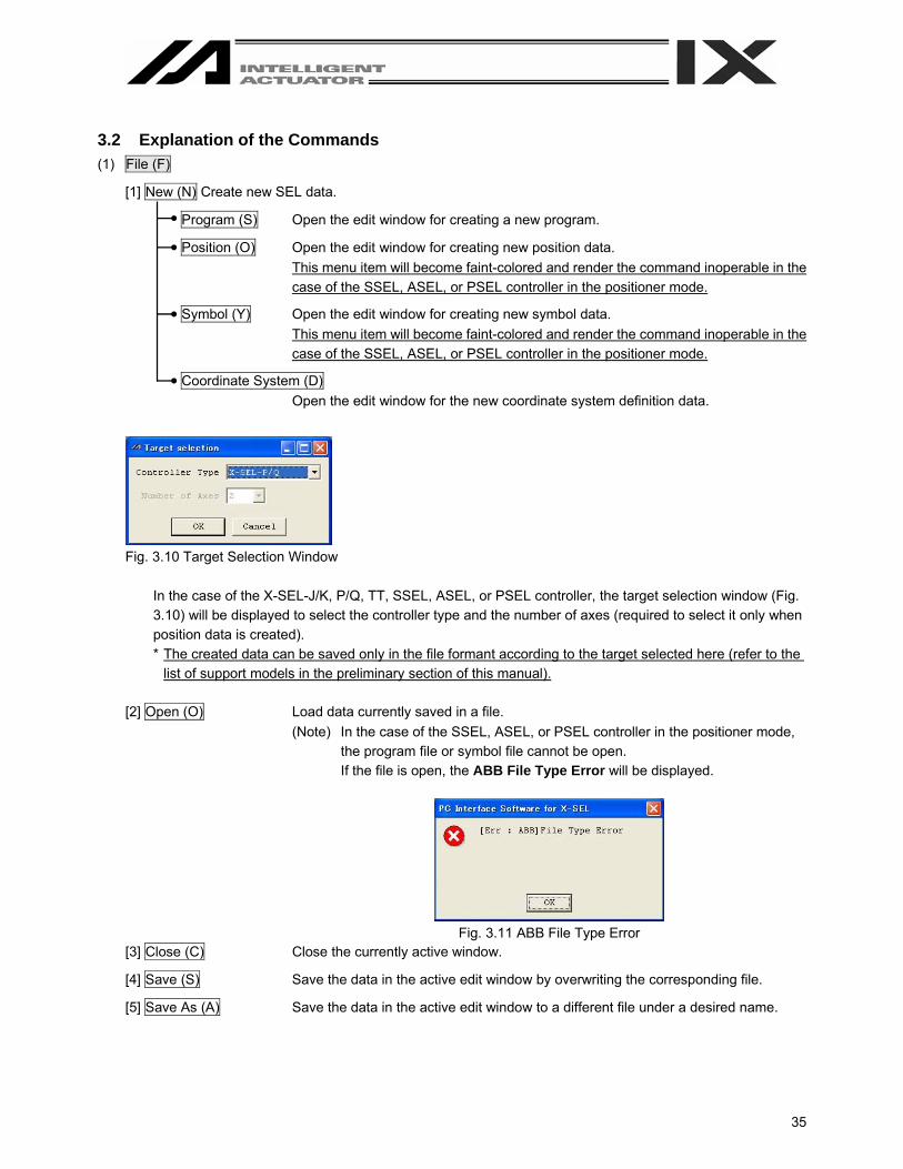
3.2 Explanation of the Commands (1) File (F)
[1] New (N) Create new SEL data.
Program (S) Open the edit window for creating a new program.
Position (O) Open the edit window for creating new position data. This menu item will become faint-colored and render the command inoperable in the case of the SSEL, ASEL, or PSEL controller in the positioner mode.
Symbol (Y) Open the edit window for creating new symbol data. This menu item will become faint-colored and render the command inoperable in the case of the SSEL, ASEL, or PSEL controller in the positioner mode.
Coordinate System (D) Open the edit window for the new coordinate system definition data.
Fig. 3.10 Target Selection Window
In the case of the X-SEL-J/K, P/Q, TT, SSEL, ASEL, or PSEL controller, the target selection window (Fig. 3.10) will be displayed to select the controller type and the number of axes (required to select it only when position data is created). * The created data can be saved only in the file formant according to the target selected here (refer to the
list of support models in the preliminary section of this manual). [2] Open (O) Load data currently saved in a file.
(Note) In the case of the SSEL, ASEL, or PSEL controller in the positioner mode, the program file or symbol file cannot be open. If the file is open, the ABB File Type Error will be displayed.
Fig. 3.11 ABB File Type Error
[3] Close (C) Close the currently active window.
[4] Save (S) Save the data in the active edit window by overwriting the corresponding file.
[5] Save As (A) Save the data in the active edit window to a different file under a desired name.
36
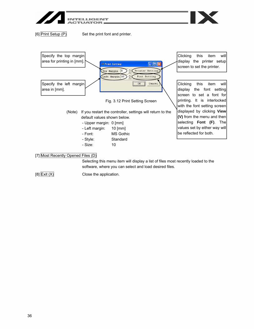
[6] Print Setup (P) Set the print font and printer.
Fig. 3.12 Print Setting Screen
(Note) If you restart the controller, settings will return to the default values shown below. - Upper margin: 0 [mm] - Left margin: 10 [mm] - Font: MS Gothic - Style: Standard - Size: 10
[7] Most Recently Opened Files (D) Selecting this menu item will display a list of files most recently loaded to the software, where you can select and load desired files.
[8] Exit (X) Close the application.
Specify the top margin area for printing in [mm].
Specify the left margin area in [mm].
Clicking this item will display the printer setup screen to set the printer.
Clicking this item will display the font setting screen to set a font for printing. It is interlocked with the font setting screen displayed by clicking View (V) from the menu and then selecting Font (F). The values set by either way will be reflected for both.
37
(2) Edit (E)
This menu lets you perform operations used in editing data.
[1] Undo (U) Up to the most recent 10 operations can be canceled. However, they cannot be canceled when you perform any of the following operations: - Transfer of data on the editing screen such as the program edit window to the
controller - Saving of data on the editing screen such as the program edit window in a file - Closing of the editing screen such as the program edit window
The following are the operations for which this function is enabled:
Input
Line Insertion
Line Deletion
Cut Paste
Program Edit Window Ο Ο Ο Ο Ο Position Edit Window Ο – – Ο Ο Symbol Edit Window Ο – – Ο Ο Parameter Edit Window Ο – – – – Coordinate System Data Edit Window Ο – – – –
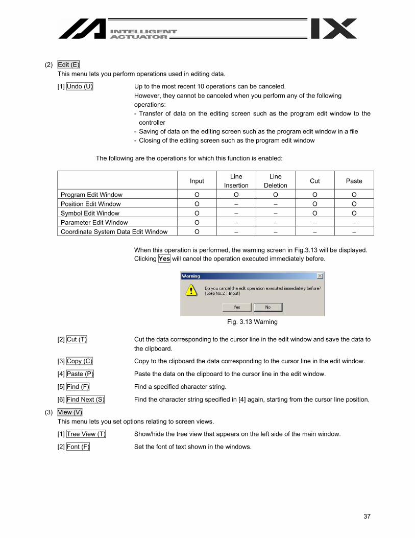
When this operation is performed, the warning screen in Fig.3.13 will be displayed. Clicking Yes will cancel the operation executed immediately before.
Fig. 3.13 Warning
[2] Cut (T) Cut the data corresponding to the cursor line in the edit window and save the data to
the clipboard.
[3] Copy (C) Copy to the clipboard the data corresponding to the cursor line in the edit window.
[4] Paste (P) Paste the data on the clipboard to the cursor line in the edit window.
[5] Find (F) Find a specified character string.
[6] Find Next (S) Find the character string specified in [4] again, starting from the cursor line position.
(3) View (V) This menu lets you set options relating to screen views.
[1] Tree View (T) Show/hide the tree view that appears on the left side of the main window.
[2] Font (F) Set the font of text shown in the windows.

38
(4) Program (S)
This menu lets you perform operations relating to programs. (Available only in the online mode.) (Refer to “4. Program Edit Window.”)
[1] Edit (E) Load a selected program from the controller for editing.
[2] Copy/Move (C) Copy/move (cut & paste) a program.
[3] Clear (L) Clear a program.
[4] Save to File (S) Save a selected program or all programs to a file under a desired name.
[5] End All Operations (T) End all programs and operations that are currently running/being performed.
(5) Position (O)
This menu lets you operate position data. (Available only in the online mode.) (Refer to “6. Position Data Edit Window.”)
[1] Edit (E) Load position data from the controller for editing.
[2] Copy/Move (C) Copy/move (cut & paste) position data.
[3] Clear (L) Clear position data.
(6) Parameter (P) This menu lets you operate parameters. (Available only in the online mode.) (Refer to “8. Parameter Edit Window.”)
[1] Edit (E) Load parameters from the controller for editing.
(7) Symbol (Y) This menu lets you operate symbol data. (Available only in the online mode.) (Refer to “9. Symbol Edit Window.”)
[1] Edit (E) Load symbol data from the controller for editing.
[2] Clear All (C) Clear all symbol data.
(8) Coordinate System (8D)
This item is displayed for X-SEL-JX/KX and PX/QX controllers. Edit the coordinate system definition data. (This is available only in the online mode.) (Refer to “10. Coordinate System Definition Data edit Window.”)
[1] Edit [E] Read the coordinate system definition data from the controller and edit the data.
[2] Clear (L) Clear the coordinate system definition data.
39
(9) Monitor (M)
This menu lets you monitor various statuses, global variables, port statuses, and so on. (Available only in the online mode.) (Refer to “11. Monitor.”)
[1] Task Status (T) Open the task status monitor window.
[2] System Status (S) Open the system status monitor window.
[3] Axis Status (A) Open the axis status monitor window.
[4] Input Port (I) Open the input port monitor window.
[5] Virtual Input Port (N) Open the virtual input port monitor window.
[6] Output port (O) Open the output port monitor window.
[7] Virtual Output Port (U) Open the virtual output port monitor window.
[8] Global Flag (F) Open the global flag monitor window.
[9] Global Integer (L) Open the global integer monitor window.
[10] Global Real (R) Open the global real variable monitor window.
[11] Global String (G) Open the global string monitor window.
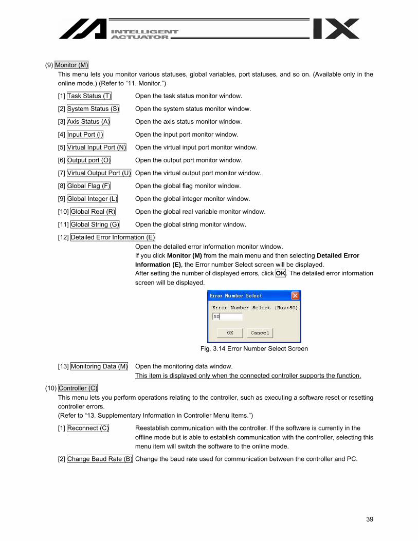
[12] Detailed Error Information (E) Open the detailed error information monitor window. If you click Monitor (M) from the main menu and then selecting Detailed Error Information (E), the Error number Select screen will be displayed. After setting the number of displayed errors, click OK. The detailed error information screen will be displayed.
Fig. 3.14 Error Number Select Screen
[13] Monitoring Data (M) Open the monitoring data window.
This item is displayed only when the connected controller supports the function.
(10) Controller (C) This menu lets you perform operations relating to the controller, such as executing a software reset or resetting controller errors. (Refer to “13. Supplementary Information in Controller Menu Items.”)
[1] Reconnect (C) Reestablish communication with the controller. If the software is currently in the offline mode but is able to establish communication with the controller, selecting this menu item will switch the software to the online mode.
[2] Change Baud Rate (B) Change the baud rate used for communication between the controller and PC.

40
[3] SEL Global Data Backup
Save to File Can save global flags, global integer variables, global real variables, and global strings.
Transfer to Controller Can transfer global flags, global integer variables, global real variables, and global strings to the controller.
[4] All Data Backup (X)
▪ Save to File(S) Save all program and position data in the controller.
▪ Transfer to Controller (L) Transfer saved program and position data to the controller.
(Note) Files collected by the SSEL, ASEL, or PSEL controller in the program mode cannot be transferred to the controller in the positioner mode. In the same way, files collected in the positioner mode cannot be transferred to the controller in the program mode. If any different file is transferred, the following message will be displayed:
Fig. 3.15 Message
[5] Positioner Mode This mode can be used when the SSEL, ASEL, or PSEL controller is under the manual mode and positioner mode.
Start Start the positioner mode.
Stop Stop the positioner mode.
Acquire Positioner Mode Information Acquire maintenance information (system data) in the positioner mode. This item is displayed for SSEL, ASEL, and PSEL controllers.
[6] Write to Flash ROM (W) Clear the data areas in the flash ROM and then write the data saved in the controller’s RAM to the flash ROM.
[7] Initialize Memory (I)
▪ Global Variable and Flag (V) Clear all global variables and flags to zero.
▪ Parameter (at the time of shipment) (S) Can return parameters to the ones at the time of shipment. This item is not displayed normally. It is a function which will become available by inputting a password. (Refer to “8.4 How to Initialize SSEL/ASEL/PSEL Parameters (at the time of shipment).”) It is a function of SSEL, ASEL, and PSEL controllers.
[8] Absolute Reset (A) Reset absolute data. This item is not displayed for XSEL-PX/QX controllers.
41
[9] Absolute Reset (Orthogonal Axis) (A)
Reset the absolute data of the orthogonal axis of the XSEL-PX/QX controller. This item is displayed for XSEL-PX/QX controllers.
[10] Absolute Reset (SCARA Axis) (Y) Reset the absolute data of the SCARA axis of the X-SEL-PX/QX controller. This item is displayed for XSEL-PX/QX controllers.
[11] Software Reset (R) Execute software reset of the controller.
[12] Reset Error (E) Reset errors present in the controller.
[13] Drive-source Recovery Request (P) Issue a drive-source recovery request to the controller.
[14] Operation-pause Reset Request (L) Issue an operation-pause reset request to the controller.
[15] About ROM Version (V) Show the various ROM version information regarding the controller.
[16] Control Constant Table Management Information (Z) Show the control constant table management information. This item is displayed for X-SEL-P/Q, PX/QX, and SSEL controllers.
[17] Positioner Mode Management information Show the operation mode and management number with regard to the positioner mode of SSEL, ASEL, and PSEL controllers. This item is displayed for SSEL, ASEL, and PSEL controllers.
(11) Tool (T) This menu lets you specify settings relating to this application.
[1] Environment Setup (S) Set items that define how the application is run.
(12) Window (W) This menu lets you change how the windows are displayed.
[1] Cascade (C) Cascade all open windows diagonally from top to bottom.
[2] Tile Vertically (V) Arrange all open windows vertically without overlapping.
[3] Tile Horizontally (H) Arrange all open windows horizontally without overlapping.
[4] Minimize All (M) Minimize all open windows (reduce them to icons).
[5] Arrange Icons (A) Arrange minimized windows (window icons).
(13) Help (H)
[1] About This Software (A) Show the version information of this software.

42
3.3 Explanation of the Toolbar
This section explains the toolbar (Fig. 3.16) shown at the top of the main window (below the menu bar).
Fig. 3.16 Toolbar
Open File Same as clicking File (F) and then selecting Open (O).
Save Same as clicking File (F) and then selecting Save (S).
Edit Program Same as clicking Program (S) and then selecting Edit (E).
Edit Position Same as clicking Position (O) and then selecting Edit (E).
Edit Parameter Same as clicking Parameter (P) and then selecting Edit (E).
Edit Symbol Same as clicking Symbol (Y) and then selecting Edit (E).
Edit Coordinate System Definition Data
Same as clicking Coordinate System (D) and then selecting Edit (E). This item is displayed for X-SEL-JX/KX and PX/QX controllers.
Monitor Input Port Same as clicking Monitor (M) and then selecting Input Port (I).
Monitor Virtual Input Port
Same as clicking Monitor (M) and then selecting Virtual Input Port (N).
Monitor Output Port Same as clicking Monitor (M) and then selecting Output Port (O).
Monitor Virtual Output Port
Same as clicking Monitor (M) and then selecting Virtual Output Prot (U).
Monitor Global Flag Same as clicking Monitor (M) and then selecting Global Flag (F).
Monitor Global Integer Variable
Same as clicking Monitor (M) and then selecting Global Integer (L).
Monitor Global Real Variable
Same as clicking Monitor (M) and then selecting Global Real (R).
Monitor Global String Variable
Same as clicking Monitor (M) and then selecting Global String (G).
43
End All Operations Same as clicking Program (S) and then selecting End All Programs (T).
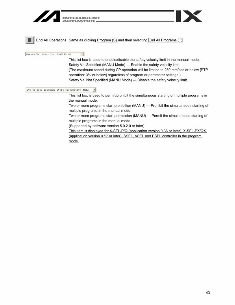
This list box is used to enable/disable the safety velocity limit in the manual mode. Safety Vel Specified (MANU Mode) --- Enable the safety velocity limit. (The maximum speed during CP operation will be limited to 250 mm/sec or below [PTP operation: 3% or below] regardless of program or parameter settings.) Safety Vel Not Specified (MANU Mode) --- Disable the safety velocity limit.
This list box is used to permit/prohibit the simultaneous starting of multiple programs in the manual mode. Two or more programs start prohibition (MANU) --- Prohibit the simultaneous starting of multiple programs in the manual mode. Two or more programs start permission (MANU) --- Permit the simultaneous starting of multiple programs in the manual mode. (Supported by software version 5.0.2.0 or later) This item is displayed for X-SEL-P/Q (application version 0.36 or later), X-SEL-PX/QX (application version 0.17 or later), SSEL, ASEL and PSEL controller in the program mode.

44
3.4 Tree View
You can display various data edit windows in the online mode by double-clicking the corresponding items displayed in the tree view (Fig. 3.4) that appears on the left side of the main window.
You can show or hide the tree view by clicking View (V) from the menu bar and then selecting Tree View (T).
Controller model The example of Fig. 3.17 also applies to X-SEL-P/Q, TT, SSEL, ASEL, and PSEL controllers.
Fig. 3.17 Tree View (X-SEL-J/K)
Remaining steps that can be stored in the controller
Currently registered programs Number of registered steps in ( ) Program name in [ ] (if a symbol is registered)
Unregistered programs
Position data edit item Double-click to open the position edit window.
“Driver,” “Encoder” and “I/O System Device” will be displayed for X-SEL-P/Q, SSEL, ASEL, and PSEL controllers.
Parameter edit items Double-click a desired parameter category to open the corresponding edit window.
Symbol edit items Double-click a desired symbol category to open the corresponding edit window.
45
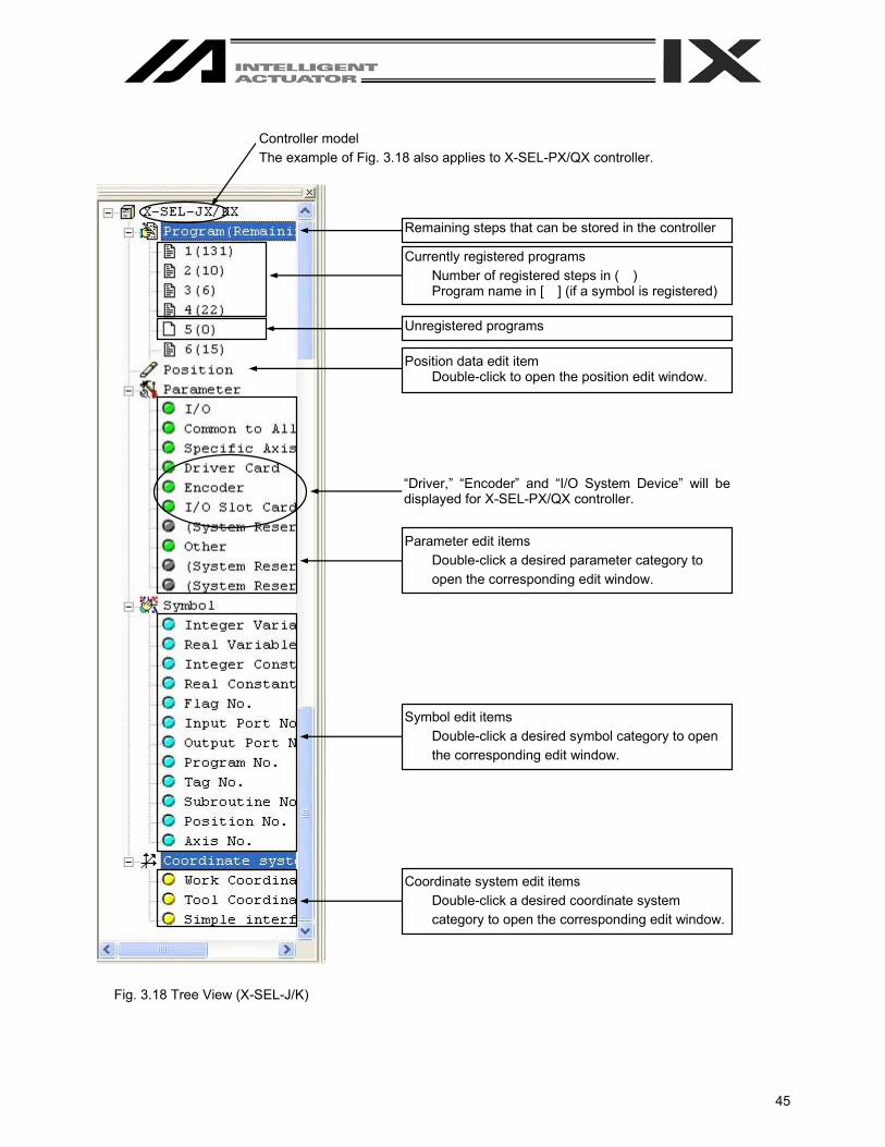
Controller model The example of Fig. 3.18 also applies to X-SEL-PX/QX controller.
Fig. 3.18 Tree View (X-SEL-J/K)
Remaining steps that can be stored in the controller
Currently registered programs Number of registered steps in ( ) Program name in [ ] (if a symbol is registered)
Unregistered programs
Position data edit item Double-click to open the position edit window.
“Driver,” “Encoder” and “I/O System Device” will be displayed for X-SEL-PX/QX controller.
Parameter edit items Double-click a desired parameter category to open the corresponding edit window.
Symbol edit items Double-click a desired symbol category to open the corresponding edit window.
Coordinate system edit items Double-click a desired coordinate system category to open the corresponding edit window.

46
4. Program Edit Window 4.1 Explanation of the Items Displayed in the Program Edit Window (1) Click Program (S) from the menu bar, and then select Edit (E). (2) When the program number selection window opens, select the program you want to edit, and then click Load.
Program name assigned in the symbol edit window
Fig. 4.1 Program Number Selection
(3) The program edit window will open. This window has the following controls and fields.
No. Step number. B Use this field to set a breakpoint. (Supported only in the online edit mode.)
Click the “B” field in the line you want to set a breakpoint for. Once a breakpoint is set, “B” will be shown in the field.
E Enter a desired extended condition. N Specify reversing “N” of the input condition. Cnd * Enter a desired input condition. Cmnd Enter a desired SEL command.
Double-clicking this field or pressing the F1 key will open the SEL Command Explanation window (Fig. 4.5). This window provides an explanation of each SEL command. You can select a desired command in this window and input it to the step data.
Operand 1 * Enter desired operand 1. Operand 2 * Enter desired operand 2. Pst * Enter a desired output (operand 3). Comment Enter a command, if necessary (using up to 18 single-byte characters).
You can also double-click this field to modify a part of the comment currently entered. * Press F11 to find a specific symbol in the input condition/operand fields.
In the case of the SSEL, ASEL, or PSEL controller, the number of remaining steps will be 2000 or less.
47
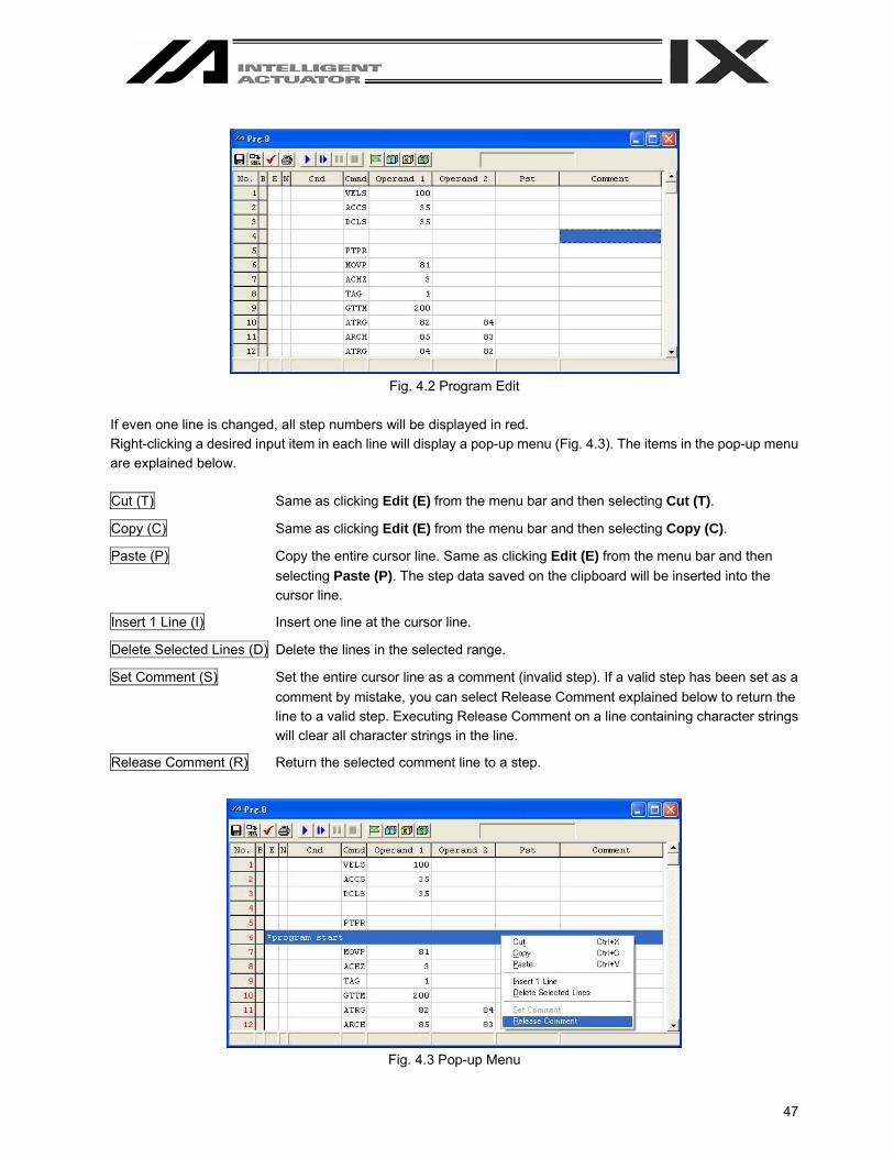
Fig. 4.2 Program Edit
If even one line is changed, all step numbers will be displayed in red. Right-clicking a desired input item in each line will display a pop-up menu (Fig. 4.3). The items in the pop-up menu are explained below. Cut (T) Same as clicking Edit (E) from the menu bar and then selecting Cut (T).
Copy (C) Same as clicking Edit (E) from the menu bar and then selecting Copy (C).
Paste (P) Copy the entire cursor line. Same as clicking Edit (E) from the menu bar and then selecting Paste (P). The step data saved on the clipboard will be inserted into the cursor line.
Insert 1 Line (I) Insert one line at the cursor line.
Delete Selected Lines (D) Delete the lines in the selected range.
Set Comment (S) Set the entire cursor line as a comment (invalid step). If a valid step has been set as a comment by mistake, you can select Release Comment explained below to return the line to a valid step. Executing Release Comment on a line containing character strings will clear all character strings in the line.
Release Comment (R) Return the selected comment line to a step.
Fig. 4.3 Pop-up Menu

48
In the program edit window, selecting Edit (E) from the menu and then Undo (U) can cancel up to the most recent 10 operations. Alternatively, pressing the Ctrl key and Z key simultaneously can cancel the operations. However, the cancel function will become disabled when any of the following operations is performed: - Transfer of data on the edit screen to the controller - Saving data on the edit screen to a file - Closing of the edit screen When this operation is performed, the warning screen in Fig. 4.4 will be displayed. Clicking Yes will cancel the operation executed immediately before.
Fig. 4.4 Warning
Double-clicking the Cmnd field or pressing the F1 key will open the SEL Command Explanation window. Use
this window as a reference when editing data.
Fig. 4.5 SEL Command Explanation (Example for in the case of X-SEL-J/K)
Pressing the F2 key can change data in the cell partially. (Example: MOVP → MOVL)
49
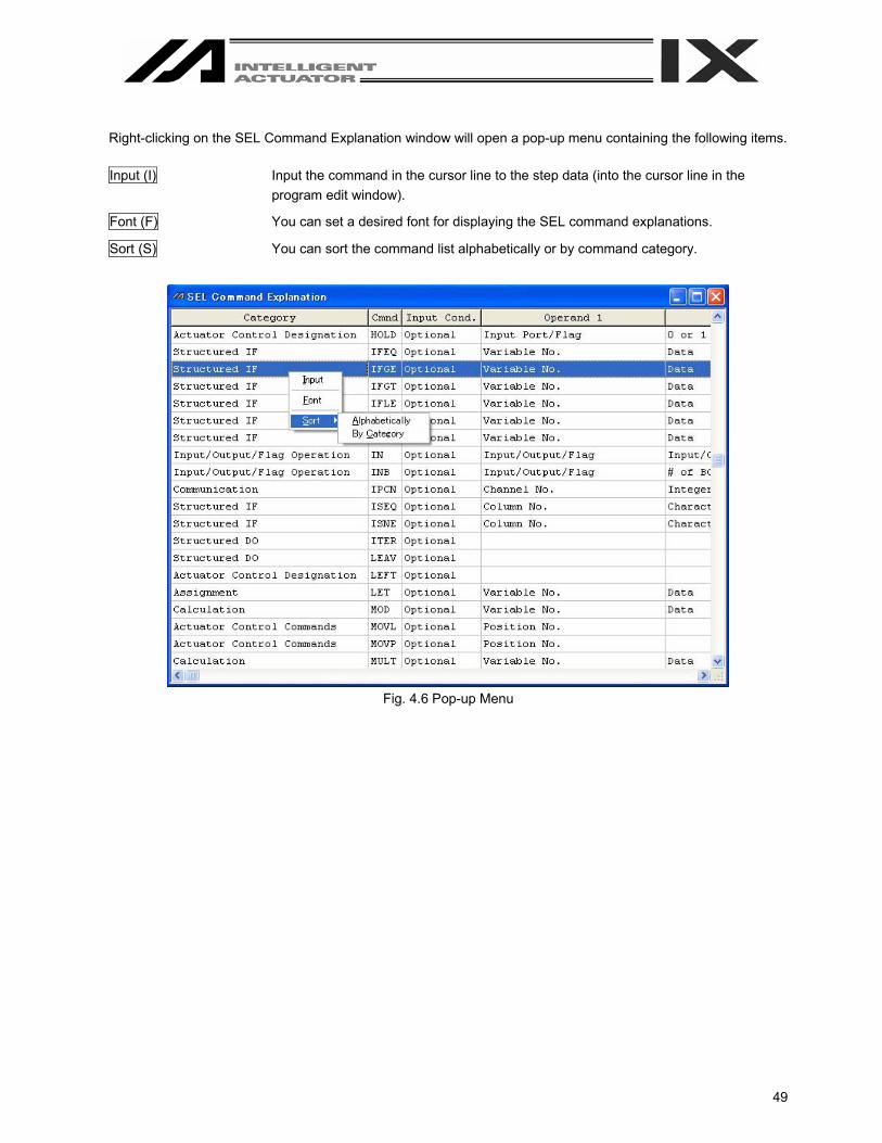
Right-clicking on the SEL Command Explanation window will open a pop-up menu containing the following items. Input (I) Input the command in the cursor line to the step data (into the cursor line in the
program edit window).
Font (F) You can set a desired font for displaying the SEL command explanations.
Sort (S) You can sort the command list alphabetically or by command category.
Fig. 4.6 Pop-up Menu
50
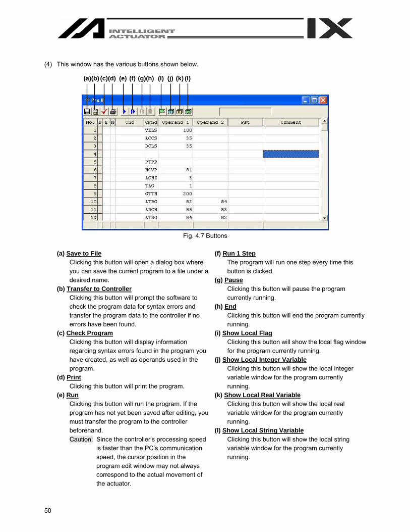
(4) This window has the various buttons shown below.
Fig. 4.7 Buttons
(a) Save to File
Clicking this button will open a dialog box where you can save the current program to a file under a desired name.
(b) Transfer to Controller Clicking this button will prompt the software to check the program data for syntax errors and transfer the program data to the controller if no errors have been found.
(c) Check Program Clicking this button will display information regarding syntax errors found in the program you have created, as well as operands used in the program.
(d) Print Clicking this button will print the program.
(e) Run Clicking this button will run the program. If the program has not yet been saved after editing, you must transfer the program to the controller beforehand. Caution: Since the controller’s processing speed
is faster than the PC’s communication speed, the cursor position in the program edit window may not always correspond to the actual movement of the actuator.
(f) Run 1 Step The program will run one step every time this button is clicked.
(g) Pause Clicking this button will pause the program currently running.
(h) End Clicking this button will end the program currently running.
(i) Show Local Flag Clicking this button will show the local flag window for the program currently running.
(j) Show Local Integer Variable Clicking this button will show the local integer variable window for the program currently running.
(k) Show Local Real Variable Clicking this button will show the local real variable window for the program currently running.
(l) Show Local String Variable Clicking this button will show the local string variable window for the program currently running.
(a)(b) (c)(d) (e) (f) (g)(h) (I) (j) (k) (l)
51
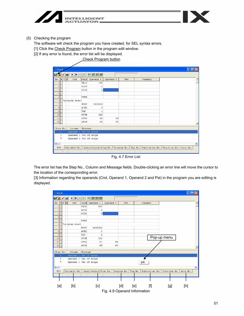
(5) Checking the program
The software will check the program you have created, for SEL syntax errors. [1] Click the Check Program button in the program edit window. [2] If any error is found, the error list will be displayed.
Check Program button
Fig. 4.7 Error List
The error list has the Step No., Column and Message fields. Double-clicking an error line will move the cursor to the location of the corresponding error. [3] Information regarding the operands (Cnd, Operand 1, Operand 2 and Pst) in the program you are editing is displayed.
[a] [b] [c] [d] [e] [f] [g] [h] Fig. 4.9 Operand Information
Pop-up menu

52
[a] Syntax Error
Message (error content)
[b] Variable No. Use Condition Variable No. Category (Integer, real number) Scope (Global, local) * If the applicable variable number is specified indirectly, the Category and Scope fields will show
“Unknown.
[c] Input/Output/Flag No. Port/Flag No. Category (Input Port No., Output Port No. or Flag No.) Scope (Global or Local) * If the applicable port/flag number is specified indirectly, the Category and Scope fields will show
“Unknown.”
[d] Program No. Use Condition Program No.
[e] Tag No. Use Condition Tag No. (Tag number in use) Declaration/Call
[f] Subroutine No. Use Condition Subroutine No. Declaration/Call
[g] Position No. Use Condition Position No.
[h] Axis No. Use Condition Axis No. * If a symbol is used in any of the numbers in [b] through [h], the corresponding definition value will be
displayed in the margin.
The above information is displayed in an itemized list at the bottom of the program edit window. You can double-click a desired item to move the cursor to the corresponding program.
You can also right-click the list to display a pop-up menu and hide the list or sort the records.

53
4.2 Saving a Program and Closing the Edit Window (1) Saving to a file the program data you are editing
Click the Save to File button in the program edit window. This is the same as clicking File (F) and then selecting Save As (A).
(2) Transferring to the controller the program data you are editing You can save the program data you are editing to the controller’s memory. Click the Transfer to Controller button in the program edit window. This button is selectable only in the online edit mode.
If the program contains any error, the error will be displayed and the program will not be transferred to the controller.
(3) Writing to the flash ROM
Once the program has been transferred to the controller, the following confirmation dialog box with the message, “Write Flash ROM?” will be displayed.
Fig. 4.10 Confirmation
(X-SEL-J/K, P/Q, TT, SSEL, ASEL, PSEL) Fig. 4.11 Confirmation (X-SEL-JX/KX, PX/QX)
Click and select a desired item (Program, etc.) to write to the flash ROM. Click Yes (Y) → The memory data will be written to the flash ROM.
Click No (N) → The memory data will not be written to the flash ROM. If No (N) is selected, the controller will clear all data in its memory after a reset (i.e., after the controller power is reconnected or a software reset is executed), and then load the data from the flash ROM. (The controller will operate in accordance with the transferred data until a reset is executed.)
(4) Closing the program edit window Attempting to close the program edit window will display the following confirmation dialog box with the message, “Save edited data in the Controller?”
Fig. 4.12 Confirmation
Yes (Y) The edited data will be transferred to the controller → (3), “Writing to the flash ROM”
No (N) The software will close the program edit window without saving the edited data.
Cancel The software will cancel the operation and return to the program edit window.
54
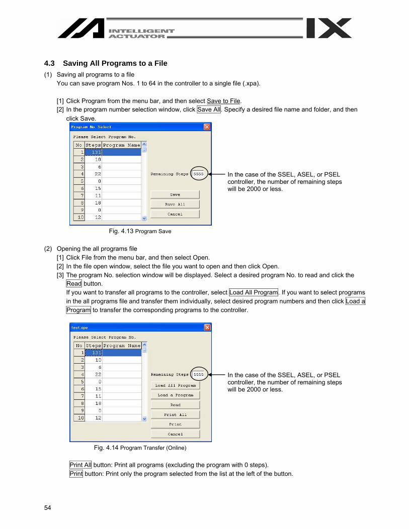
4.3 Saving All Programs to a File (1) Saving all programs to a file
You can save program Nos. 1 to 64 in the controller to a single file (.xpa). [1] Click Program from the menu bar, and then select Save to File. [2] In the program number selection window, click Save All. Specify a desired file name and folder, and then
click Save.
Fig. 4.13 Program Save
(2) Opening the all programs file
[1] Click File from the menu bar, and then select Open. [2] In the file open window, select the file you want to open and then click Open. [3] The program No. selection window will be displayed. Select a desired program No. to read and click the
Read button. If you want to transfer all programs to the controller, select Load All Program. If you want to select programs in the all programs file and transfer them individually, select desired program numbers and then click Load a Program to transfer the corresponding programs to the controller.
Fig. 4.14 Program Transfer (Online)
Print All button: Print all programs (excluding the program with 0 steps). Print button: Print only the program selected from the list at the left of the button.
In the case of the SSEL, ASEL, or PSEL controller, the number of remaining steps will be 2000 or less.
In the case of the SSEL, ASEL, or PSEL controller, the number of remaining steps will be 2000 or less.
55
(3) Important note on transferring an all programs file to the controller [1] Transferring an all programs file to the controller with Load All Program will clear the existing programs of
Nos. 1 to 64 in the controller. If necessary, back up all current programs in the controller beforehand. [2] If the all programs file includes any program that contains symbols and the symbols are not defined in the
controller’s memory, an error will occur when the applicable program is transferred to the controller. If an error occurs, none of the programs will be transferred to the controller. Therefore, if the applicable symbol data is saved to a file, transfer the symbol definition file first. If there is no symbol definition file, define the applicable symbols in the symbol edit window and then transfer the definitions to the controller, before transferring the all programs file again.
[3] If the all programs file contains any error, the error window will be displayed and none of the programs will
be transferred to the controller. In this case, double-click the error shown in the error window to open the program file that contains the applicable error. Correct the error, and then save the file by overwriting. If multiple errors exist, correct all errors. When all errors have been corrected, transfer the programs to the controller again. The procedure in [3] provides an important recovery method for program files containing errors.
(4) Saving the all programs file
[1] If the program files read from the all programs file are saved as the all programs file, click Save (S).
[2] If the program files are saved individually, click Save as (A).

56
4.4 Running the Program
You can run the program in the program edit window. To run the program you are editing, transfer it to the controller first. Note) Once transferred to the controller, the program can be run without being written to the flash ROM first. If the
program is not written to the flash ROM, however, it will be lost once the controller power is reconnected or a software reset is executed.
Run: Clicking this button will run the program. Run 1 Step: The program will run one step every time this button is clicked. Pause: Clicking this button will pause the program currently running. Clicking it again will resume the
program. Clicking Run or Run 1 Step will resume the program.
End: Clicking this button will end the program currently running. Breakpoint: You can pause the program in a desired step. “B” will appear/disappear every time the field is
clicked. Note) A breakpoint will be cleared once the controller power is reconnected or a software reset is
executed.
Fig. 4.15 Program Run
Cursor colors Green: The program is paused (by step operation,
by a breakpoint, by the pause button, by the SSPG command, etc.).
Red: The program is waiting (in response to the TIMW, WTxx, WZxx, WRIT or READ command, waiting for a servo command to be completed, etc.).
Blue: Any condition other than those represented by a green or red cursor.
Background colors Gray: The program is running. White: The program is not running.

57
5. Copying/Moving/Clearing a Program 5.1 Program Copy/Move Window
The steps to copy or move a program to other program number are explained below. (1) Click Program (S) from the menu bar, and then select Copy/Move (C). (2) The program copy/move window will open.
Fig. 5.1 Program Copy/Move
Double-click the source program you want to copy or move. Click the destination program you want to copy or move the source program to. To copy the program, click Copy. To move the program, click Move. Both operations are done in the memory. Clicking Cancel will cancel the selected operation.
(3) Writing to the flash ROM
When the copy or move is completed, the following confirmation dialog box with the message, “Write Flash ROM?” will be displayed.
Fig. 5.2 Confirmation
(X-SEL-J/K, P/Q, TT, SSEL, ASEL, PSEL) Fig. 5.3 Confirmation
(X-SEL-JX/KX, PX/QX)
Click and select a desired item (Program, etc.) to write to the flash ROM. Click Yes (Y) → The memory data will be written to the flash ROM. Click No (N) → The memory data will not be written to the flash ROM.
Once the controller is reset (the controller power is reconnected or a software reset is executed), the original program arrangement before the copy or move will be restored.
In the case of the SSEL, ASEL, or PSEL controller, the number of remaining steps will be 2000 or less.
Program number to copy/move from Program number to copy/move to

58
5.2 Program Clear Window
The steps to clear a program are explained below. (1) Click Program (S) from the menu bar, and then select Clear (L). (2) The program clear window will open.
Fig. 5.4 Program Clear
Click the program you want to clear. You can select multiple programs by dragging the mouse or pressing the Ctrl key and ↑ ↓ key simultaneously. Next, click Clear. (This operation is done in the memory.) Clicking Cancel will cancel the operation. When clearing all programs in the controller, click the All Clear button.
(3) Writing to the flash ROM
When the clear is completed, the following confirmation dialog box with the message, “Write Flash ROM?” will be displayed.
Fig. 5.5 Confirmation
(X-SEL-J/K, P/Q, TT, SSEL, ASEL, PSEL) Fig. 5.6 Confirmation
(X-SEL-JX/KX, PX/QX) Click and select a desired item (Program, etc.) to write to the flash ROM. Click Yes (Y) → The memory data will be written to the flash ROM.
Click No (N) → The memory data will not be written to the flash ROM. Once the controller is reset (the controller power is reconnected or a software reset is executed), the cleared program will be restored.
In the case of the SSEL, ASEL, or PSEL controller, the number of remaining steps will be 2000 or less.
59
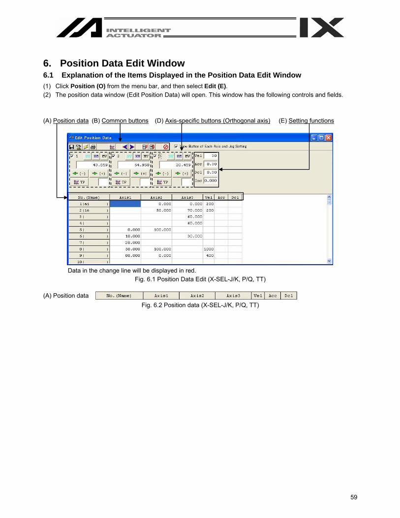
6. Position Data Edit Window 6.1 Explanation of the Items Displayed in the Position Data Edit Window (1) Click Position (O) from the menu bar, and then select Edit (E). (2) The position data window (Edit Position Data) will open. This window has the following controls and fields. (A) Position data (B) Common buttons (D) Axis-specific buttons (Orthogonal axis) (E) Setting functions
Data in the change line will be displayed in red.
Fig. 6.1 Position Data Edit (X-SEL-J/K, P/Q, TT) (A) Position data
Fig. 6.2 Position data (X-SEL-J/K, P/Q, TT)

60
(A) Position data (C) Common buttons (F) Axis-specific buttons (SCARA axis) (G) Setting functions (H) Movement selection
Fig. 6.3 Position Data Edit (X-SEL-JX/KX)
(A) Position data
Fig. 6.4 Position Data (X-SEL-JX/KX) (A) Position data (B) Common buttons (F) Axis-specific buttons (SCARA axis) (G) Setting functions (SCARA axis) (H) Movement selection
Fig. 6.5 Position Data Edit (X-SEL-PX/QX)
(A) Position data
SCARA axis position Orthogonal axis position Fig. 6.6 Position Data (X-SEL-PX/QX)
(F) Axis-specific
buttons
(Orthogonal axis)
SCARA axis setting
Orthogonal axis setting
(E) Setting functions
(Orthogonal axis)
61
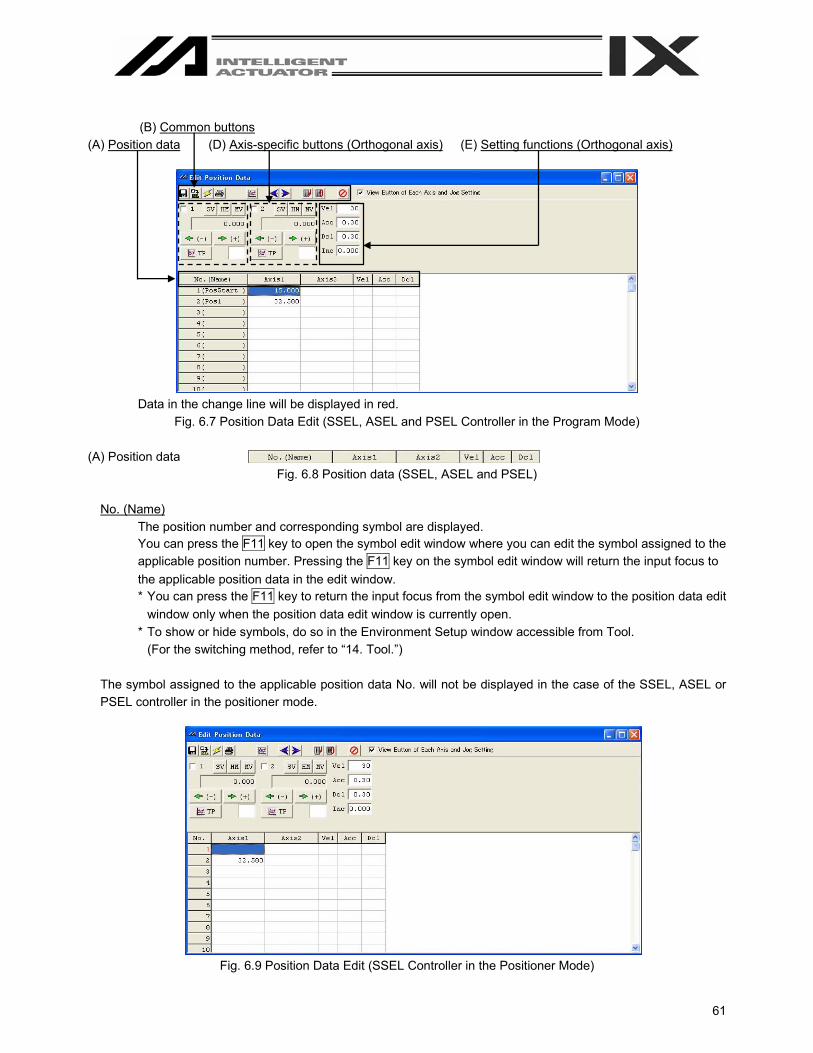
(B) Common buttons (A) Position data (D) Axis-specific buttons (Orthogonal axis) (E) Setting functions (Orthogonal axis)
Data in the change line will be displayed in red.
Fig. 6.7 Position Data Edit (SSEL, ASEL and PSEL Controller in the Program Mode) (A) Position data
Fig. 6.8 Position data (SSEL, ASEL and PSEL)
No. (Name) The position number and corresponding symbol are displayed. You can press the F11 key to open the symbol edit window where you can edit the symbol assigned to the applicable position number. Pressing the F11 key on the symbol edit window will return the input focus to the applicable position data in the edit window. * You can press the F11 key to return the input focus from the symbol edit window to the position data edit
window only when the position data edit window is currently open. * To show or hide symbols, do so in the Environment Setup window accessible from Tool.
(For the switching method, refer to “14. Tool.”) The symbol assigned to the applicable position data No. will not be displayed in the case of the SSEL, ASEL or PSEL controller in the positioner mode.
Fig. 6.9 Position Data Edit (SSEL Controller in the Positioner Mode)

62
Axis 1 to 4
Specify each desired position for Axis 1 to Axis 4. In the case of the JX/KX or PX/QX controller, specify a desired position for each SCARA axis. The setting range is from –99999.999 to 99999.999.
Axis 5, 6 Specify a desired position for Axis 5 and Axis 6. The setting range is from -99999.999 to 99999.99.
Vel Specify a desired velocity. The setting range is from 1 to the value set in All-axis common parameter, No. 21 “Operating velocity MAX (orthogonal axis), CP velocity MAX (SCARA axis).”
Acc Specify a desired acceleration. The setting range is from 0.01 to the value set in All-axis common parameter, No. 22 “Acceleration MAX (orthogonal axis), CP acceleration MAX (SCARA axis).”
Dcl Specify a desired deceleration. The setting range is from 0.01 to the value set in All-axis common parameter, “Deceleration MAX (orthogonal axis), CP deceleration MAX (SCARA axis).”
In the position edit window, clicking Edit (E) from the menu bar and then selecting Undo (U) can cancel the most recent 10 operations excluding line insertion and line deletion. Alternatively, pressing the Ctrl key and Z key simultaneously can cancel the operations. However, the cancel function will become disabled when any of the following operations is performed: - Transfer of data on the edit screen to the controller - Saving data on the edit screen to a file - Closing of the edit screen When this operation is performed, the warning screen in Fig. 6.10 will be displayed. Clicking Yes will cancel the operation executed immediately before.
Fig. 6.10 Warning
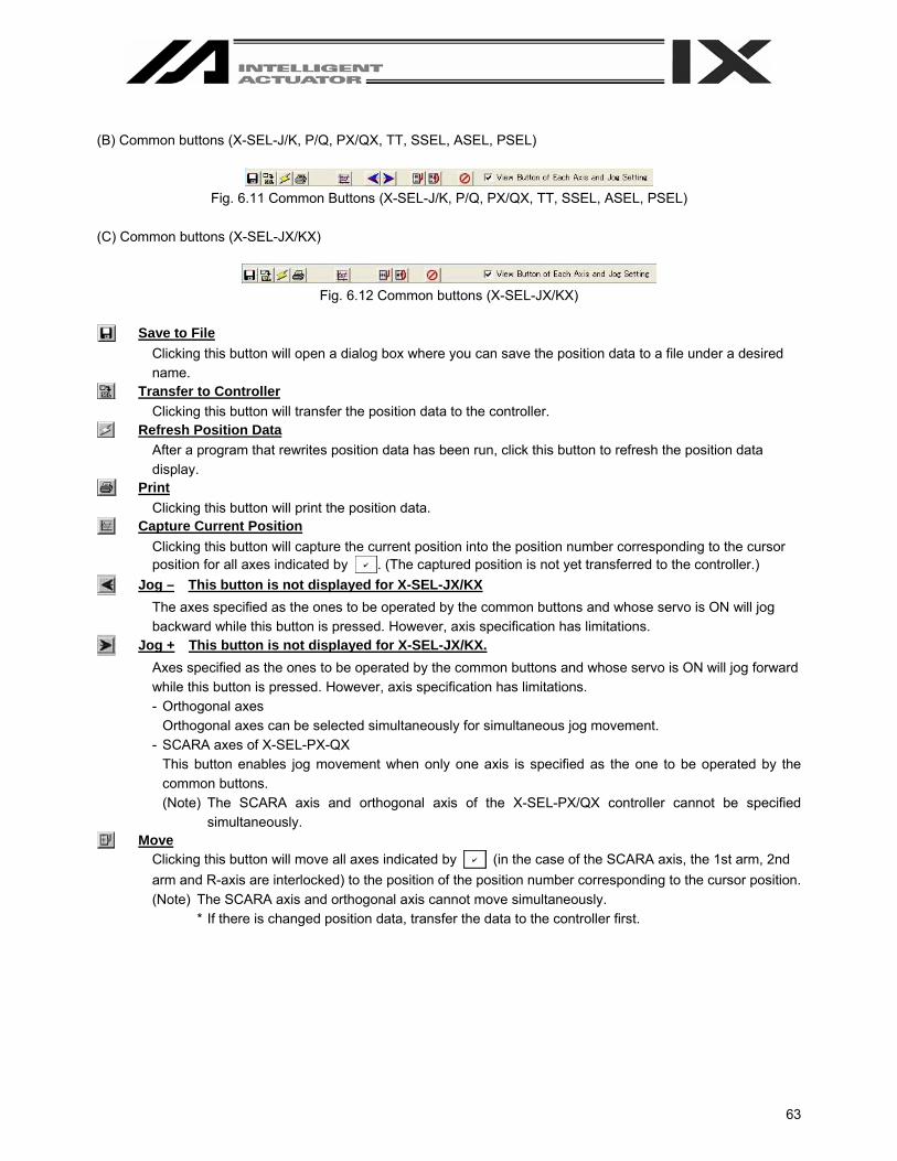
63
(B) Common buttons (X-SEL-J/K, P/Q, PX/QX, TT, SSEL, ASEL, PSEL)
Fig. 6.11 Common Buttons (X-SEL-J/K, P/Q, PX/QX, TT, SSEL, ASEL, PSEL)
(C) Common buttons (X-SEL-JX/KX)
Fig. 6.12 Common buttons (X-SEL-JX/KX)
Save to File
Clicking this button will open a dialog box where you can save the position data to a file under a desired name.
Transfer to Controller Clicking this button will transfer the position data to the controller.
Refresh Position Data After a program that rewrites position data has been run, click this button to refresh the position data display.
Print Clicking this button will print the position data.
Capture Current Position Clicking this button will capture the current position into the position number corresponding to the cursor position for all axes indicated by . (The captured position is not yet transferred to the controller.)
Jog – This button is not displayed for X-SEL-JX/KX The axes specified as the ones to be operated by the common buttons and whose servo is ON will jog backward while this button is pressed. However, axis specification has limitations.
Jog + This button is not displayed for X-SEL-JX/KX. Axes specified as the ones to be operated by the common buttons and whose servo is ON will jog forward while this button is pressed. However, axis specification has limitations. - Orthogonal axes
Orthogonal axes can be selected simultaneously for simultaneous jog movement. - SCARA axes of X-SEL-PX-QX
This button enables jog movement when only one axis is specified as the one to be operated by the common buttons. (Note) The SCARA axis and orthogonal axis of the X-SEL-PX/QX controller cannot be specified
simultaneously. Move
Clicking this button will move all axes indicated by (in the case of the SCARA axis, the 1st arm, 2nd arm and R-axis are interlocked) to the position of the position number corresponding to the cursor position. (Note) The SCARA axis and orthogonal axis cannot move simultaneously.
* If there is changed position data, transfer the data to the controller first.
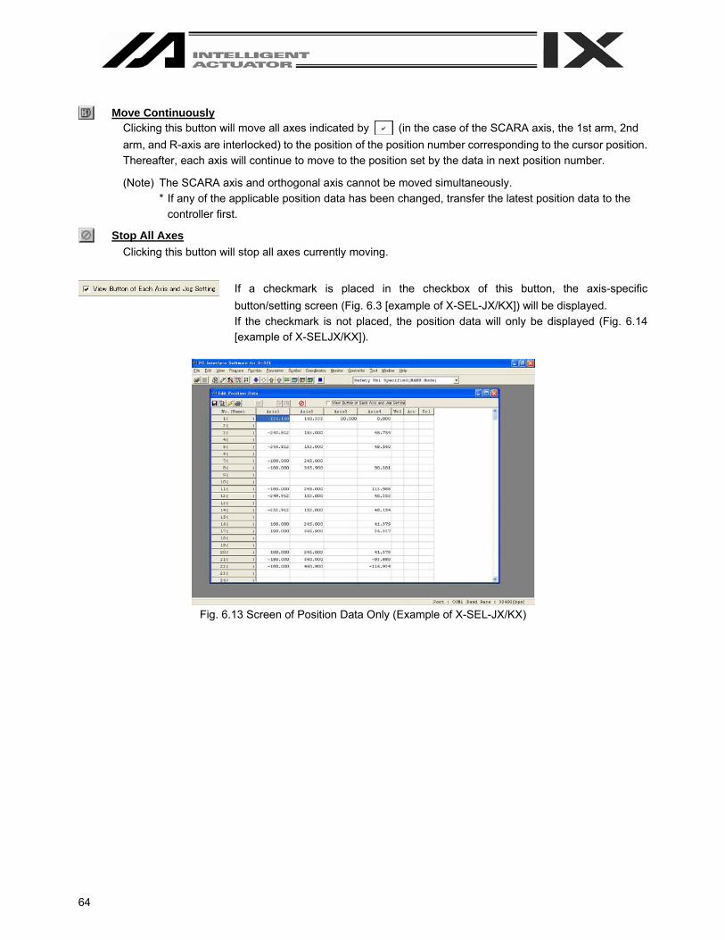
64
Move Continuously
Clicking this button will move all axes indicated by (in the case of the SCARA axis, the 1st arm, 2nd arm, and R-axis are interlocked) to the position of the position number corresponding to the cursor position. Thereafter, each axis will continue to move to the position set by the data in next position number.
(Note) The SCARA axis and orthogonal axis cannot be moved simultaneously. * If any of the applicable position data has been changed, transfer the latest position data to the
controller first.
Stop All Axes Clicking this button will stop all axes currently moving.
If a checkmark is placed in the checkbox of this button, the axis-specific
button/setting screen (Fig. 6.3 [example of X-SEL-JX/KX]) will be displayed. If the checkmark is not placed, the position data will only be displayed (Fig. 6.14 [example of X-SELJX/KX]).
Fig. 6.13 Screen of Position Data Only (Example of X-SEL-JX/KX)

65
(D) Axis-specific buttons (Orthogonal axis)
Fig. 6.14 Axis-specific buttons (Orthogonal axis)
Clicking this button will turn the servo of the selected axis OFF if it is currently ON, or turn the axis servo ON if it is currently OFF. (The button is shown in light blue when the servo is ON.)
Clicking this button will perform homing if the servo of the selected axis is ON. (The button will be shown in light blue after homing.)
Clicking this button will move the selected axis to the position specified by the data in the position number corresponding to the cursor position, if the axis servo is ON. (The button remains yellow while the axis is moving.)
The selected axis will jog forward while this button is clicked, if the axis servo is ON.
If a value (0.001 to 1) is entered in the Inc. field in the setting function group, the axis will perform inching. In this case, one click will move the axis by one inching distance.
The selected axis will jog backward while this button is clicked, if the axis servo is ON. If a value (0.001 to 1) is entered in the Inc. field in the setting function group, the axis will perform inching. In this case, one click will move the axis by one inching distance.
Clicking this button will capture the current position of the selected axis into the position number corresponding to the cursor position. (The captured position is not yet transferred to the controller.)
Current position of the selected axis
Error code
Axis number
Select the axis you want to move using the common buttons.
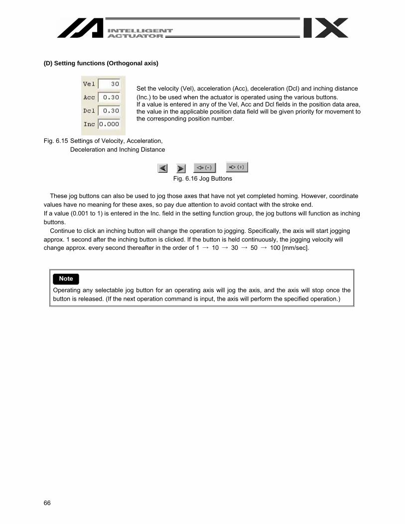
66
(D) Setting functions (Orthogonal axis)
Fig. 6.15 Settings of Velocity, Acceleration,
Deceleration and Inching Distance
Fig. 6.16 Jog Buttons
These jog buttons can also be used to jog those axes that have not yet completed homing. However, coordinate
values have no meaning for these axes, so pay due attention to avoid contact with the stroke end. If a value (0.001 to 1) is entered in the Inc. field in the setting function group, the jog buttons will function as inching buttons.
Continue to click an inching button will change the operation to jogging. Specifically, the axis will start jogging approx. 1 second after the inching button is clicked. If the button is held continuously, the jogging velocity will change approx. every second thereafter in the order of 1 → 10 → 30 → 50 → 100 [mm/sec].
Operating any selectable jog button for an operating axis will jog the axis, and the axis will stop once the button is released. (If the next operation command is input, the axis will perform the specified operation.)
Set the velocity (Vel), acceleration (Acc), deceleration (Dcl) and inching distance (Inc.) to be used when the actuator is operated using the various buttons. If a value is entered in any of the Vel, Acc and Dcl fields in the position data area, the value in the applicable position data field will be given priority for movement to the corresponding position number.

67
(F) Axis-specific buttons (SCARA axis)
Fig. 6.17 Axis-specific buttons (SCARA axis)
Clicking any axis button will turn the servo of all axes ON/OFF. (The button is shown in light blue when the servo is ON.)
Clicking this button will turn the servo of all axes ON when the axis servo is OFF, or turn the servo of all axes OFF when the axis servo is ON.
Clicking this button will move the selected axis to the position specified by the data in the position number corresponding to the cursor position, if the axis servo is ON. (The button remains yellow while the axis is moving.)
The selected axis will perform jogging while this button is pressed, if the axis servo is ON.
If a value (0.01 to 1.00) is entered in the Inc field under Setting Function, the axis will perform inching. In this case, one click will move the axis by one inching distance.
Clicking this button will capture the current position of the selected axis into the position number corresponding to the cursor position. (The captured position is not yet transferred to the controller.)
Clicking this button will capture the current position of the selected axis into the position number corresponding to the cursor position. (The captured position is not yet transferred to the controller.)
Current position of the selected axis
Error code
Axis number
Select the axis you want to move using the common buttons.
“W” in the case of the work coordinate system or “A” in the case of each axis system

68
(G) Setting functions (SCARA axis)
Set the velocity (Vel), acceleration (Acc), deceleration (Dcl) and inching distance (Inc.) to be used when the actuator is operated using the various buttons.
Fig. 6.18 Settings of Velocity, Acceleration, Deceleration and Inching Distance
Jog/Inc
Vel [mm/sec], Acc [G], Dcl [G], Inc [mm] The above settings are effective on both the work and tool coordinate systems. Vel [%], Acc [%], Dcl [%], Inc [deg] The above settings are effective only when the “each Axis” system is selected. The jog button functions as the incremental button, if a numeric value (0.01 to 1.00) is entered in the Inc field under Setting Function.
Move Vel [%], Acc [%], Dcl [%] Set the moving speed that applies when the MV button is clicked. Movement occurs in the form of PTP operation. Each percentage setting indicates a percentage with respect to a corresponding parameter setting. Vel [%] (percentage with respect to “Axis Parameter No. 28: “PTP speed MAX”) Acc [%] (percentage with respect to “Axis Parameter No. 134: “PTP acceleration MAX”) Dcl [%] (percentage with respect to “Axis Parameter No. 135: “PTP deceleration MAX”)
Separate sets of data are set for Jog/Inc and Move. Vel, Acc, Dcl and Inc are set in two different units.

69
(H) Movement Selection
Various buttons are provided to set Current arm system, Jog movement coordinate sys., Work coord sys slct No. and Tool coord sys slct No.
Fig. 6.19 Selection of Current Arm System and Various Coordinate Systems Current arm system
The arm can be changed by clicking the Change button.
Fig. 6.20 Current Arm System Selection
Caution: If the arm system is changed for a stationary axis, the newly selected arm may move occasionally.
Jog movement coordinate sys.
The coordinate system can be changed by clicking the ▼ button. XY work coordinate system (Can be offset using Work Coordinate System Selection No.) XY tool coordinate system Each axis system
Fig. 6.21 Selection of Jog Movement Coordinate System Work coord sys slct No.
A desired work coordinate system selection No. can be selected by clicking the Change button.
Fig. 6.22 Selection of Work Coordinate System Tool coord sys slct No.
A desired tool coordinate system selection No. can be selected by clicking the Change button.
Fig. 6.23 Selection of Tool Coordinate System

70
6.2 Saving Position Data and Closing the Edit Window (1) Saving to a file the position data you are editing
Click the Save to File button in the position edit window. This is the same as clicking File (F) and then selecting Save As (A).
(2) Transferring to the controller the position data you are editing
Click the Transfer to Controller button in the position edit window. The position data you are editing will be saved to the controller’s memory. This button is selectable only in the online edit mode.
(3) Writing to the flash ROM
Once the program has been transferred to the controller, the following confirmation dialog box with the message, “Write Flash ROM?” will be displayed.
Fig. 6.24 Confirmation
(X-SEL-J/K, P/Q, TT, SSEL, ASEL, PSEL) Fig. 6.25 Confirmation (X-SEL-JX/KX, PX/QX)
Click and select a desired item (Position, etc.) to write to the flash ROM. Click Yes → The memory data will be written to the flash ROM.
Click No → The memory data will not be written to the flash ROM.
(4) Closing the point edit window
Attempting to close the point edit window will open the following confirmation dialog box with the message, “Save edited data in the Controller?”
Fig. 6.8 Confirmation
Yes The edited data will be transferred to the controller → (3), “Writing to the flash ROM” No The software will close the point edit window without saving the edited data. Cancel The software will cancel the operation and return to the position edit window.
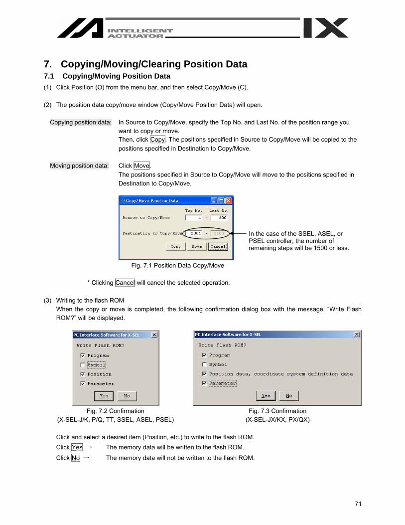
71
7. Copying/Moving/Clearing Position Data 7.1 Copying/Moving Position Data (1) Click Position (O) from the menu bar, and then select Copy/Move (C). (2) The position data copy/move window (Copy/Move Position Data) will open.
Copying position data: In Source to Copy/Move, specify the Top No. and Last No. of the position range you want to copy or move. Then, click Copy. The positions specified in Source to Copy/Move will be copied to the positions specified in Destination to Copy/Move.
Moving position data: Click Move.
The positions specified in Source to Copy/Move will move to the positions specified in Destination to Copy/Move.
Fig. 7.1 Position Data Copy/Move
* Clicking Cancel will cancel the selected operation. (3) Writing to the flash ROM
When the copy or move is completed, the following confirmation dialog box with the message, “Write Flash ROM?” will be displayed.
Fig. 7.2 Confirmation
(X-SEL-J/K, P/Q, TT, SSEL, ASEL, PSEL) Fig. 7.3 Confirmation
(X-SEL-JX/KX, PX/QX) Click and select a desired item (Position, etc.) to write to the flash ROM. Click Yes → The memory data will be written to the flash ROM.
Click No → The memory data will not be written to the flash ROM.
In the case of the SSEL, ASEL, or PSEL controller, the number of remaining steps will be 1500 or less.

72
7.2 Clearing Position Data (1) Click Position (O) from the menu bar, and then select Clear (L). (2) The position data clear window (Clear Position Data) will open.
Fig. 7.4Position Data Clear
In Clear Scope, specify the Top No. and Last No. of the position range you want to clear. Then, click Clear. Clicking Cancel will cancel the operation.
(3) Writing to the flash ROM
When the clear is completed, the following confirmation dialog box with the message, “Write Flash ROM?” will be displayed.
Fig. 7.5 Confirmation
(X-SEL-J/K, P/Q, TT, SSEL, ASEL, PSEL) Fig. 7.6 Confirmation
(X-SEL-JX/KX, PX/QX) Click and select a desired item (Position, etc.) to write to the flash ROM. Click Yes → The memory data will be written to the flash ROM.
Click No → The memory data will not be written to the flash ROM.

73
8. Parameter Edit Window 8.1 Explanation of the Parameter Edit Window (1) Click Parameter (P) from the menu bar, and then select Edit (E). (2) The parameter edit window (Edit Parameter) will open.
You can select a desired parameter and change the value. Values that are grayed out are read-only and cannot be changed.
Save to File Clicking this button will open a dialog box where you can save the parameter data to a file under a desired name.
Transfer to Controller Clicking this button will transfer the parameter data to the controller.
Print Clicking this button will print the parameter data.
Fig. 8.1 Parameter Edit (X-SEL-J/K, JX/KX, TT)
* The above window shows I/O parameters. You can display other parameters by clicking each category tab.
“Driver,” “Encoder” and “I/O System Device” will be displayed for X-SEL-P/Q, PX/QX, SSEL, ASEL, and PSEL controllers.

74
In the parameter edit window, clicking Edit (E) from the menu bar and then selecting Undo (U) can cancel up to the most recent 10 input operations. Alternatively, pressing the Ctrl key and Z key simultaneously can cancel the operations. However, the cancel function will become disabled when any of the following operations is performed: - Transfer of data on the edit screen to the controller - Saving data on the edit screen to a file - Closing of the edit screen When this operation is performed, the warning screen in Fig. 8.2 will be displayed. Clicking Yes will cancel the operation executed immediately before.
Fig. 8.2 Warning
8.2 Saving Parameter Data and Closing the Edit Window (1) Saving to a file the parameter data you are editing
Click the Save to File button in the parameter edit window. This is the same as clicking File (F) and then selecting Save As (A).
(2) Transferring to the controller the parameter data you are editing
You can save the parameter data you are editing to the controller’s memory. Click the Transfer to Controller button in the parameter edit window.
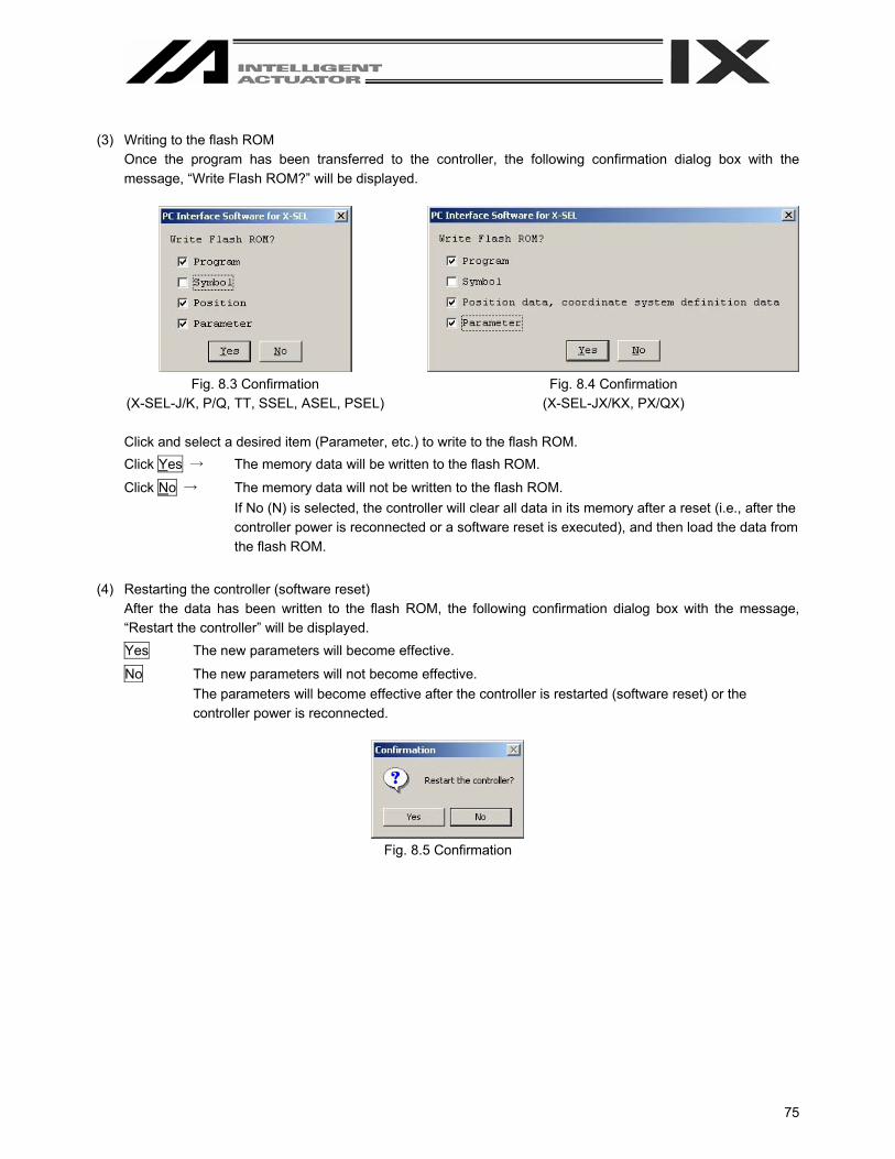
75
(3) Writing to the flash ROM
Once the program has been transferred to the controller, the following confirmation dialog box with the message, “Write Flash ROM?” will be displayed.
Fig. 8.3 Confirmation
(X-SEL-J/K, P/Q, TT, SSEL, ASEL, PSEL) Fig. 8.4 Confirmation
(X-SEL-JX/KX, PX/QX) Click and select a desired item (Parameter, etc.) to write to the flash ROM. Click Yes → The memory data will be written to the flash ROM.
Click No → The memory data will not be written to the flash ROM. If No (N) is selected, the controller will clear all data in its memory after a reset (i.e., after the controller power is reconnected or a software reset is executed), and then load the data from the flash ROM.
(4) Restarting the controller (software reset)
After the data has been written to the flash ROM, the following confirmation dialog box with the message, “Restart the controller” will be displayed. Yes The new parameters will become effective.
No The new parameters will not become effective. The parameters will become effective after the controller is restarted (software reset) or the controller power is reconnected.
Fig. 8.5 Confirmation
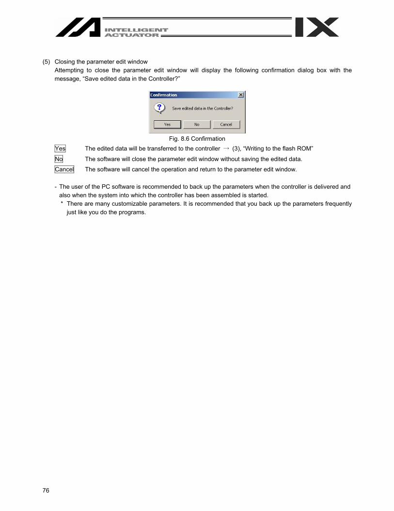
76
(5) Closing the parameter edit window
Attempting to close the parameter edit window will display the following confirmation dialog box with the message, “Save edited data in the Controller?”
Fig. 8.6 Confirmation
Yes The edited data will be transferred to the controller → (3), “Writing to the flash ROM”
No The software will close the parameter edit window without saving the edited data.
Cancel The software will cancel the operation and return to the parameter edit window.
- The user of the PC software is recommended to back up the parameters when the controller is delivered and also when the system into which the controller has been assembled is started. * There are many customizable parameters. It is recommended that you back up the parameters frequently
just like you do the programs.

77
8.3 Transferring a Parameter File
Pay attention to parameter categories when transferring parameter data files to the controller. The controller is shipped with its axis-related parameters set, for each axis, to values appropriate for the type of the actuator connected.
There are three categories of axis-related parameters: axis-specific parameters, driver card parameters and encoder parameters.
Exercise due caution when using an existing file containing customized parameters. Note) If parameter data is lost during parameter writing to the flash ROM due to main power OFF or any other
factor, all parameters will be rewritten to initial values. In the case of the X-SEL-P/Q or PX/QX controller, an error will be detected after power reconnection or software reset since system-specific settings are lost immediately after parameter initialization. Under such conditions, all parameters cannot be transferred to the controller together. Handle the problem in accordance with the “Parameter Recovery Method for X-SEL-P/Q and PX/QX Controllers” in the Appendix at the back of this manual.
8.3.1 Selecting Categories of Parameters to Be Transferred (1) Select Open from the File menu or click the corresponding button in the toolbar. In the file selection dialog box,
select the parameter file (extension: .xpm) you want to transfer to the controller. Load the file into the PC software and open the parameter edit window.
(2) Click the Transfer to Controller button in the parameter edit window. (3) The Select Parameter Category window (Fig. 8.7) will be displayed. In the case of X-SEL-JX/KX, the screen not
showing Actuator specific parameters, transfer from axis # to axis # (Fig. 8.8) will be displayed. In the case of SSEL, the screen not showing Controller basic unit Transmit options (Fig. 8.9) will be displayed. This window has the following items: (The specific items will vary depending on the controller.)
Fig. 8.7 Select Parameter Category Window
(This window is supported by PC software version 3.0.1.0 or later.)
Checkboxes for selecting transfer destination axes
Checkboxes for selecting transfer source axes
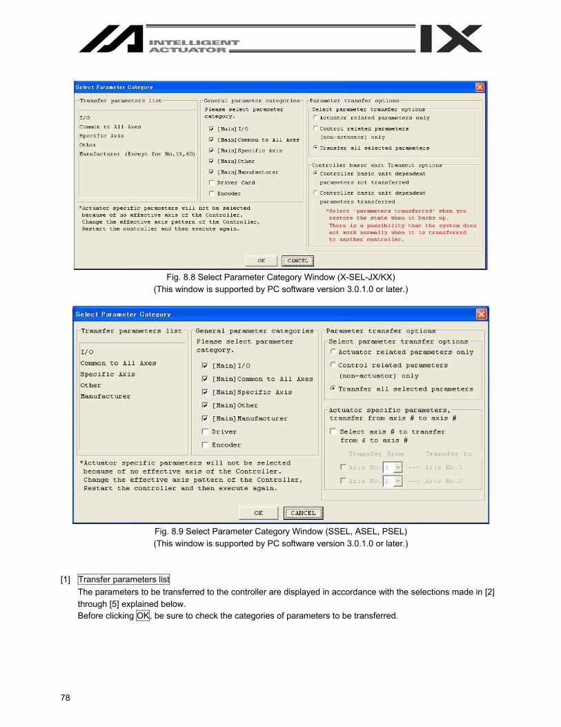
78
Fig. 8.8 Select Parameter Category Window (X-SEL-JX/KX)
(This window is supported by PC software version 3.0.1.0 or later.)
Fig. 8.9 Select Parameter Category Window (SSEL, ASEL, PSEL) (This window is supported by PC software version 3.0.1.0 or later.)
[1] Transfer parameters list
The parameters to be transferred to the controller are displayed in accordance with the selections made in [2] through [5] explained below. Before clicking OK, be sure to check the categories of parameters to be transferred.
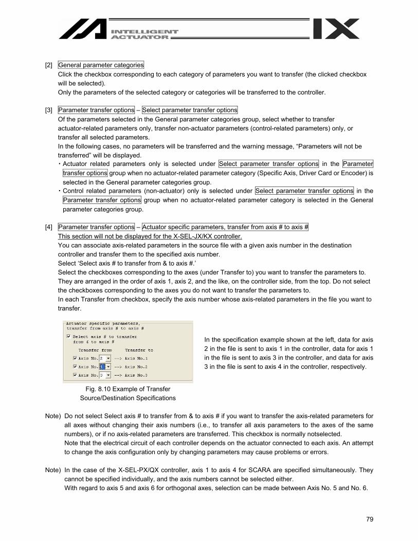
79
[2] General parameter categories
Click the checkbox corresponding to each category of parameters you want to transfer (the clicked checkbox will be selected). Only the parameters of the selected category or categories will be transferred to the controller.
[3] Parameter transfer options – Select parameter transfer options
Of the parameters selected in the General parameter categories group, select whether to transfer actuator-related parameters only, transfer non-actuator parameters (control-related parameters) only, or transfer all selected parameters. In the following cases, no parameters will be transferred and the warning message, “Parameters will not be transferred” will be displayed. ・ Actuator related parameters only is selected under Select parameter transfer options in the Parameter
transfer options group when no actuator-related parameter category (Specific Axis, Driver Card or Encoder) is selected in the General parameter categories group.
・ Control related parameters (non-actuator) only is selected under Select parameter transfer options in the Parameter transfer options group when no actuator-related parameter category is selected in the General parameter categories group.
[4] Parameter transfer options – Actuator specific parameters, transfer from axis # to axis #
This section will not be displayed for the X-SEL-JX/KX controller. You can associate axis-related parameters in the source file with a given axis number in the destination controller and transfer them to the specified axis number. Select ‘Select axis # to transfer from & to axis #.’ Select the checkboxes corresponding to the axes (under Transfer to) you want to transfer the parameters to. They are arranged in the order of axis 1, axis 2, and the like, on the controller side, from the top. Do not select the checkboxes corresponding to the axes you do not want to transfer the parameters to. In each Transfer from checkbox, specify the axis number whose axis-related parameters in the file you want to transfer.
In the specification example shown at the left, data for axis 2 in the file is sent to axis 1 in the controller, data for axis 1 in the file is sent to axis 3 in the controller, and data for axis 3 in the file is sent to axis 4 in the controller, respectively.
Fig. 8.10 Example of Transfer Source/Destination Specifications
Note) Do not select Select axis # to transfer from & to axis # if you want to transfer the axis-related parameters for
all axes without changing their axis numbers (i.e., to transfer all axis parameters to the axes of the same numbers), or if no axis-related parameters are transferred. This checkbox is normally notselected. Note that the electrical circuit of each controller depends on the actuator connected to each axis. An attempt to change the axis configuration only by changing parameters may cause problems or errors.
Note) In the case of the X-SEL-PX/QX controller, axis 1 to axis 4 for SCARA are specified simultaneously. They
cannot be specified individually, and the axis numbers cannot be selected either. With regard to axis 5 and axis 6 for orthogonal axes, selection can be made between Axis No. 5 and No. 6.

80
[5] Parameter transfer options – Controller basic unit Transmit options
Select whether to enable transfer of controller basic unit dependent parameters. If controller basic unit dependent parameters are not included in the selections made in [2], [3] and [4], selecting Controller basic unit type dependent parameters transferred will not transfer the applicable parameters. Normally, select Controller basic unit dependent parameters not transferred. Select Controller basic unit type dependent parameters transferred only in the following conditions: ・ The flash ROM was corrupted, and the parameters must be rewritten. ・ Parameters for a wrong controller type were written by mistake, and the parameters must be rewritten.
8.3.2 Default Specifications
In the Parameter transfer options group, you can set the default setting only for Select parameter transfer options in the window accessible by selecting Environment Setup from the Tool menu (Fig. 8.11).
Fig. 8.11 Environment Setup

81
8.4 How to Initialize SSEL/ASEL/PSEL Parameters (at the time of shipment) Note: Initialization of parameters (at the time of shipment) can be performed only for SSEL, ASEL and PSEL
controllers. (1) Right-click a blank space in the tool bar (refer to Fig. 8.12) while pressing the Ctrl button. The Input Password
will be displayed.
Fig. 8.12 Menu Bar
Fig. 8.13 Input Password Screen
(2) Enter a password (5119) in the displayed Input Password screen. The Parameter of Shipping menu will be
displayed in the Initialize Memory menu (Fig. 8.14).
*The password will be valid until the end of application once it has been entered.
Fig. 8.14 Menu Bar (Parameter Initialization [Shipment Values]: Example of SSEL)
Right-click a blank space in the tool bar while pressing Ctrl.

82
(3) Selecting the displayed menu Parameter of Shipping will display a dialog in Fig. 8.15. If you have no problem,
click Yes.
Fig. 8.15 Warning Dialog
(4) After completion of rewriting, write the parameters to the flash ROM
Note: Encoder parameters are not initialized. Because of this an unexpected error may be detected when the actuator different from the one at the time of shipment is connected.

83
9. Symbol Edit Window 9.1 About Symbols
In the X-SEL controller, variable numbers, flag numbers and other values can be treated as symbols. (1) Values supporting symbol conversion
The following values can be treated as symbols: Variable number, flag number, tag number, subroutine number, program number, position number, input port number, output port number, axis number, constant
(2) Symbol description rules
[1] First character: A single-byte alphabet or single-byte underscore. [2] Second and subsequent characters: Any characters corresponding to ASCII codes 0x21 to 0x7e that can
be entered from the keyboard. [3] Maximum number of characters: 9 single-byte characters (or 8 single-byte characters in the case of a
character string literal). [4] Definition of the same symbol for two or more values within a given function is prohibited.
(The same symbol can be defined for two or more local values that are each used in a different program.) [5] Definition of the same symbol for two or more flag numbers, input ports and/or output ports is prohibited.
(The same symbol can be defined for two or more local flags/ports that are each used in a different program.)
[6] Definition of the same symbol for two or more integer variable numbers and/or real variable numbers is prohibited. (The same symbol can be defined for two or more local variables that are each used in a different program.)
[7] Definition of the same symbol for two or more integer constants and/or real constants is prohibited. (3) Number of symbol definitions: Up to 1,000 (Up to 500 for SSEL, ASEL and PSEL controllers) (4) Number of symbol uses allowed in commands: Up to 5,000 times including character string literals (Up to 2,000
times for SSEL, ASEL and PSEL controllers) * Defining the input condition, operands 1 and 2 and output in a step all using symbols is equivalent to four
symbol uses in one step.

84
9.2 Explanation of the Symbol Edit Window (1) Click Symbol (Y) from the menu bar, and then select Edit (E). (2) The symbol edit window (Edit Symbol) will open.
Save to File Clicking this button will open a dialog box where you can save the parameter data to a file under a desired name.
Transfer to Controller Clicking this button will transfer the parameter data to the controller.
Print Clicking this button will print the parameter data.
Select the scope as Global or Local. If Local is selected, specify a desired program number.
Fig. 9.1 Symbol Edit
* The above symbol edit window is for integer variables. You can display other symbols by clicking each category tab.
(3) Right-click in the symbol edit window will display the pop-up menu which has the options of Cut (T), Copy (C)
and Paste (P). The cut or copied data can be pasted only in the symbol edit window. (The data cannot be pasted in the other windows such as the program edit window and position data edit window.) (Supported by software version 4.0.0.0 or later)

85
(4) A symbol character string can be dragged and dropped between the symbol edit window and program edit
window. By dragging a symbol character string on the symbol edit window while pressing the Ctrl key and then dropping it into any cell of Cnd, Operand 1, Operand 2 and Pst, the symbol character string can be copied. The reverse operation (drag & drop operation from the program edit window to the symbol edit window) is also available. (Supported by software version 4.0.0.0 or later)
Fig. 9.2 Symbol Edit Window Fig. 9.3 Program Edit Window
In the coordinate system definition data edit window, clicking Edit (E) from the menu bar and then selecting Undo (U) can cancel up to the most recent 10 input operations. Alternatively, pressing the Ctrl key and Z key simultaneously can cancel the operations. However, the cancel function will become disabled when any of the following operations is performed: - Transfer of data on the edit screen to the controller - Saving data on the edit screen to a file - Closing of the edit screen
When this operation is performed, the warning screen in Fig. 9.4 will be displayed. Clicking Yes will cancel the operation executed immediately before.
Fig. 9.4 Warning
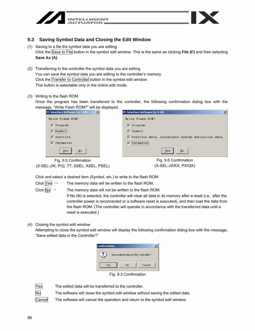
86
9.3 Saving Symbol Data and Closing the Edit Window (1) Saving to a file the symbol data you are editing
Click the Save to File button in the symbol edit window. This is the same as clicking File (F) and then selecting Save As (A).
(2) Transferring to the controller the symbol data you are editing
You can save the symbol data you are editing to the controller’s memory. Click the Transfer to Controller button in the symbol edit window. This button is selectable only in the online edit mode.
(3) Writing to the flash ROM
Once the program has been transferred to the controller, the following confirmation dialog box with the message, “Write Flash ROM?” will be displayed.
Fig. 9.5 Confirmation
(X-SEL-J/K, P/Q, TT, SSEL, ASEL, PSEL) Fig. 9.6 Confirmation
(X-SEL-JX/KX, PX/QX) Click and select a desired item (Symbol, etc.) to write to the flash ROM. Click Yes → The memory data will be written to the flash ROM.
Click No → The memory data will not be written to the flash ROM. If No (N) is selected, the controller will clear all data in its memory after a reset (i.e., after the controller power is reconnected or a software reset is executed), and then load the data from the flash ROM. (The controller will operate in accordance with the transferred data until a reset is executed.)
(4) Closing the symbol edit window
Attempting to close the symbol edit window will display the following confirmation dialog box with the message, “Save edited data in the Controller?”
Fig. 9.3 Confirmation
Yes The edited data will be transferred to the controller.
No The software will close the symbol edit window without saving the edited data.
Cancel The software will cancel the operation and return to the symbol edit window.
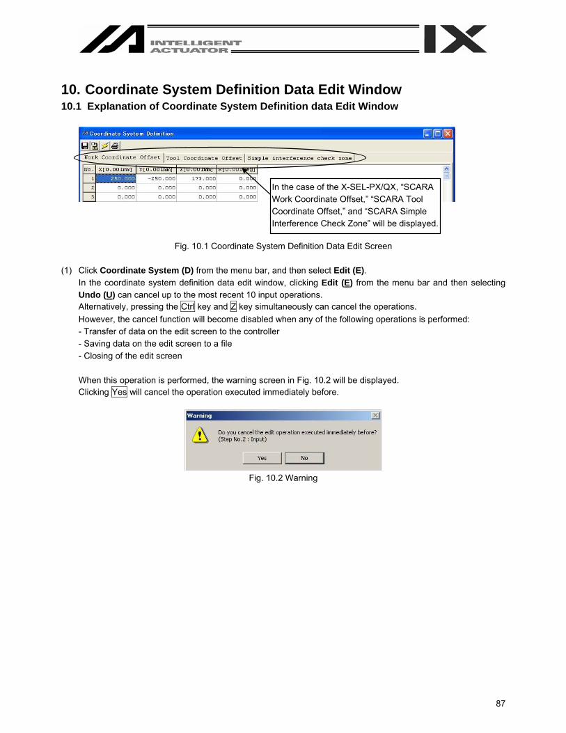
87
10. Coordinate System Definition Data Edit Window 10.1 Explanation of Coordinate System Definition data Edit Window
Fig. 10.1 Coordinate System Definition Data Edit Screen (1) Click Coordinate System (D) from the menu bar, and then select Edit (E).
In the coordinate system definition data edit window, clicking Edit (E) from the menu bar and then selecting Undo (U) can cancel up to the most recent 10 input operations. Alternatively, pressing the Ctrl key and Z key simultaneously can cancel the operations. However, the cancel function will become disabled when any of the following operations is performed: - Transfer of data on the edit screen to the controller - Saving data on the edit screen to a file - Closing of the edit screen When this operation is performed, the warning screen in Fig. 10.2 will be displayed. Clicking Yes will cancel the operation executed immediately before.
Fig. 10.2 Warning
In the case of the X-SEL-PX/QX, “SCARA Work Coordinate Offset,” “SCARA Tool Coordinate Offset,” and “SCARA Simple Interference Check Zone” will be displayed.
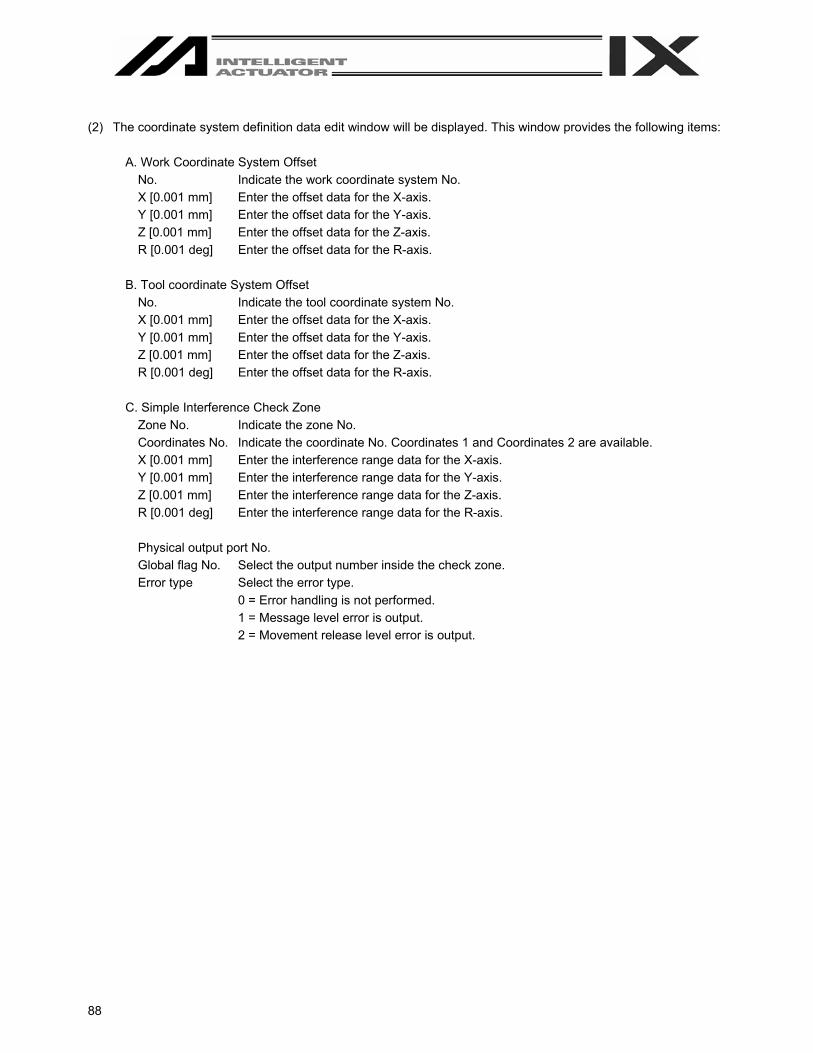
88
(2) The coordinate system definition data edit window will be displayed. This window provides the following items:
A. Work Coordinate System Offset No. Indicate the work coordinate system No. X [0.001 mm] Enter the offset data for the X-axis. Y [0.001 mm] Enter the offset data for the Y-axis. Z [0.001 mm] Enter the offset data for the Z-axis. R [0.001 deg] Enter the offset data for the R-axis.
B. Tool coordinate System Offset
No. Indicate the tool coordinate system No. X [0.001 mm] Enter the offset data for the X-axis. Y [0.001 mm] Enter the offset data for the Y-axis. Z [0.001 mm] Enter the offset data for the Z-axis. R [0.001 deg] Enter the offset data for the R-axis.
C. Simple Interference Check Zone
Zone No. Indicate the zone No. Coordinates No. Indicate the coordinate No. Coordinates 1 and Coordinates 2 are available. X [0.001 mm] Enter the interference range data for the X-axis. Y [0.001 mm] Enter the interference range data for the Y-axis. Z [0.001 mm] Enter the interference range data for the Z-axis. R [0.001 deg] Enter the interference range data for the R-axis. Physical output port No. Global flag No. Select the output number inside the check zone. Error type Select the error type.
0 = Error handling is not performed. 1 = Message level error is output. 2 = Movement release level error is output.

89
10.2 Work Coordinate System
A total of 32 different coordinates, provided as a combination of three-dimensional orthogonal coordinates and rotation axis coordinates, are defined by the offset of each axis with respect to the base coordinate system. Note that work coordinate system No. 0 is reserved in the system as the base coordinates (= work coordinate system offsets are 0).
Xofwn: X work coordinate offset Yofwn: Y work coordinate offset Zofwn: Z work coordinate offset Rofwn: R work coordinate offset Xwn: Work coordinate system, X-axis Ywn: Work coordinate system, X-axis Zwn: Work coordinate system, X-axis Rwn: Work coordinate system, X-axis (n indicates work coordinate system No.)
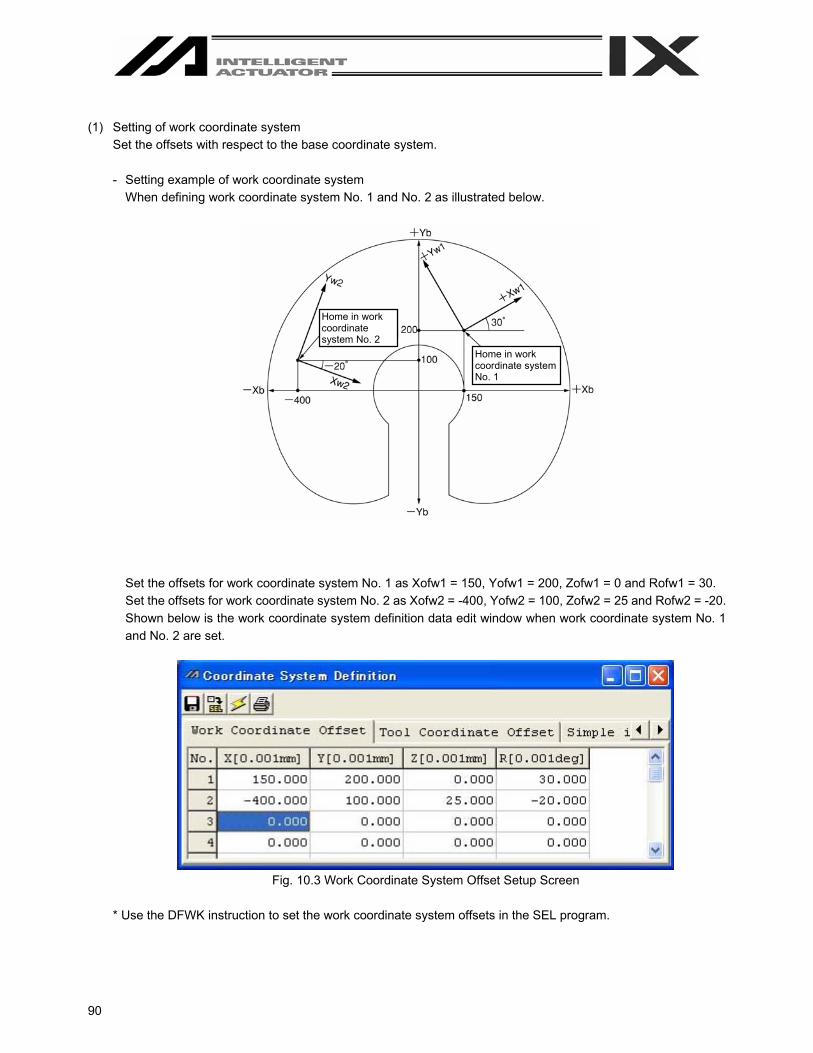
90
(1) Setting of work coordinate system
Set the offsets with respect to the base coordinate system.
- Setting example of work coordinate system When defining work coordinate system No. 1 and No. 2 as illustrated below.
Set the offsets for work coordinate system No. 1 as Xofw1 = 150, Yofw1 = 200, Zofw1 = 0 and Rofw1 = 30. Set the offsets for work coordinate system No. 2 as Xofw2 = -400, Yofw2 = 100, Zofw2 = 25 and Rofw2 = -20. Shown below is the work coordinate system definition data edit window when work coordinate system No. 1 and No. 2 are set.
Fig. 10.3 Work Coordinate System Offset Setup Screen
* Use the DFWK instruction to set the work coordinate system offsets in the SEL program.
Home in work coordinate system No. 1
Home in work coordinate system No. 2

91
(2) Positioning in a work coordinate system
Perform positioning after selecting a desired work coordinate system. Use the SLWK instruction to select a desired work coordinate system No. in the SEL program. Once set, the work coordinate system selection No. will remain effective after the program ends, and even after the power is reconnected if the system memory backup battery is installed.
[1] When performing PTP positioning to position No. 5 and No. 6 in work coordinate system No. 1:
Fig. 10.4 Position Data Screen: Work Coordinate System No. 1 Setting
Sample program : : :
SLWK 1 Select work coordinate system No. 1. SLTL 0 Select tool coordinate system No. 0. PTPR Specify right arm as the PTP target arm. MOVP 5 Move to position No. 5. MOVP 6 Move to position No. 6.
: : :
The R-axis position is shown at left (top view). The Z-axis position is as follows: Position No. 5 Zb = 0 Position No. 6 Zb = 20
In the case of X-SEL-PX/QX, “SCARA work coord sys slct No” and “SCARA tool coord sys slct No.” will be displayed.
Position no. 6
Position no. 5
Position no. 6
Position no. 5
R-axis flat D-cut surface

92
[2] When performing PTP positioning to position No. 5 and No. 6 in work coordinate system.
Fig. 10.5 Position Data Screen: Work Coordinate System No. 2 Setting
Sample program : : :
SLWK 2 Select work coordinate system No. 2. SLTL 0 Select tool coordinate system No. 0. PTPR Specify right arm as the PTP target arm.MOVP 5 Move to position No. 5. MOVP 6 Move to position No. 6.
: : :
The R-axis position is shown at left (top view). The Z-axis position is as follows: Position No. 5 Zb = 25 Position No. 6 Zb = 45
Position no. 6
Position no. 5
Position no. 6
Position no. 5
R-axis flat D-cut surface
(Negative direction)

93
10.3 Tool Coordinate System
A total of 128 different coordinates, provided as a combination of three-dimensional orthogonal coordinates and rotation axis coordinates, are defined by the dimensions (offsets) of the tool (hand etc.) installed on the tool installation surface. Note that tool coordinate system No. 0 is reserved in the system as the tool coordinate system with 0 offsets. When a defined tool coordinate system No. is selected, the tool tip, not the center of the tool installation surface, is used as the positioning destination.
Select a defined tool coordinate system and jog the R-axis, and the machine will operate as illustrated below:
R-axis
Tool
Tool tip
Xoftn: X tool coordinate offset Yoftn: Y tool coordinate offset Zoftn: Z tool coordinate offset Roftn: R tool coordinate offset Xtn: Tool Coordinate system, X-axis Ytn: Tool Coordinate system, X-axis Ztn: Tool Coordinate system, X-axis Rtn: Tool Coordinate system, X-axis (n indicate tool coordinate system No.)

94
(1) Setting of tool coordinate system
Set the offsets from the center of tool installation surface to the tool tip. - Setting example of tool coordinate system When defining tool coordinate system No. 1 as illustrated below:
Set the offsets for tool coordinate system No. 1 as Xoft1 = 45, Yoft1 = 35, Zoft1 = -10 and Roft1 =45. Shown below is the tool coordinate system definition data edit screen when tool coordinate system No. 1 is set.
Fig. 10.6 Tool Coordinate System Offset Setting Screen
*Use the DFTL instruction to set the tool coordinate system offsets in the SEL program.

95
(2) Positioning based on tool coordinate system offsets
Perform positioning after selecting a desired tool coordinate system. Use the SLTL instruction to select a desired tool coordinate system No. in the SEL program. Once set, the tool coordinate system selection No. will remain effective after the program ends, and even after the power is reconnected if the system memory backup battery is installed.
[1] When performing PTP positioning of the tool tip in tool coordinate system No. 1 to position No. 5 and No. 6
in work coordinate system No. 1:
Fig. 10.7 Tool Coordinate System Offset Setting Screen Fig. 10.8 Work Coordinate System Offset Setting Screen
Fig. 10.9 Position Data Screen: Work Coordinate System No. 1 and Tool Coordinate System No. 1 Setting
Sample program
: : :
SLWK 1 Select work coordinate system No. 1. SLTL 1 Select tool coordinate system No. 1. PTPR Specify right arm as the PTP target arm. MOVP 5 Move to position No. 5. MOVP 6 Move to position No. 6.
: : :
The Z-axis position at the tool tip is as follows: Position No. 5 Zb = 0 Position No. 6 Zb = 20 A top view is shown at the left.
Position no. 6
Position no. 5
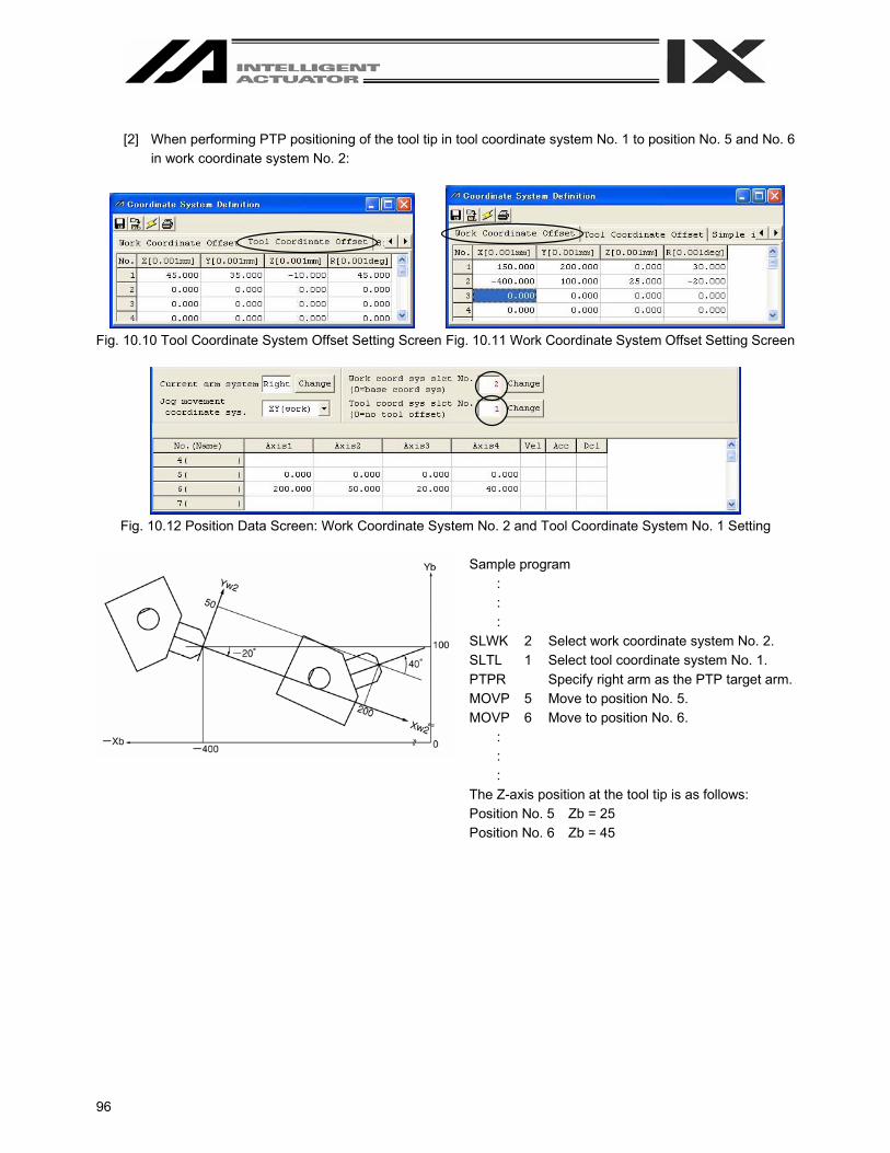
96
[2] When performing PTP positioning of the tool tip in tool coordinate system No. 1 to position No. 5 and No. 6
in work coordinate system No. 2:
Fig. 10.10 Tool Coordinate System Offset Setting Screen Fig. 10.11 Work Coordinate System Offset Setting Screen
Fig. 10.12 Position Data Screen: Work Coordinate System No. 2 and Tool Coordinate System No. 1 Setting
Sample program
: : :
SLWK 2 Select work coordinate system No. 2. SLTL 1 Select tool coordinate system No. 1. PTPR Specify right arm as the PTP target arm. MOVP 5 Move to position No. 5. MOVP 6 Move to position No. 6.
: : :
The Z-axis position at the tool tip is as follows: Position No. 5 Zb = 25 Position No. 6 Zb = 45

97
10.4 Simple Interference Check Zone
The simple interference check zone is an area set for the purpose of interference check between the robot and the peripherals. Entry of the center of tool installation surface into the simple interference check zone can be detected when tool coordinate system No. 0 (= tool coordinate system offsets are 0) is selected, while entry of the tool tip in the simple interference check zone can be detected when tool coordinate system No. 1 through 127 (= tool coordinate system offset is other than 0) is selected. (1) Note on using the simple interference check zone
Entry of the center of tool installation surface (when tool coordinate system No. 0 is selected) or tool tip (when tool coordinate system No. 1 through 127 is selected) into the simple interference check zone is detected. Entry of the circumference of the R-axis or any part of the tool other than the tip is not detected. This function does not prevent entry of the tool into the simple interference check zone. It only detects that the tool has entered the zone. Entry cannot be detected reliably unless the applicable part of the tool remains inside the simple interference check zone for at least 5msec. Accordingly, this function is intended as a simple check during low-speed operation. The actual motion differs between high-speed operation (actual operating condition) and low-speed operation. Provide a sufficient margin to prevent interference. (During high-speed operation, the tool tends to pass along a line further inward compared with low-speed operation.) The defined coordinates of the simple interference check zone are always handled as data linked to the base coordinate system (work coordinate system selection No. 0). Therefore, the position of simple interference check zone does not change even when the work coordinate system is changed. Exercise caution. If the defined coordinates of the simple interference check zone are changed, it takes 5msec before the check result reflects the new settings. During PTP operation, the tool does not follow specified routes. When operating the tool near an obstacle (including the robot body), always perform test operation at low speed and confirm that interference does not occur. Thereafter, gradually increase the speed to an appropriate level.
(2) Setting of simple interference check zone Set the simple interference check zone using the position data in the base coordinate system. Enter the maximum and minimum coordinates of the simple interference check zone. Set the boundaries of the simple interference check zone parallel with the base coordinate axes.
To set the simple interference check zone as a rectangular solid like the one shown at the left, enter the coordinates of two points in any one of the four combinations of A-G, B-H, C-E or D-F.
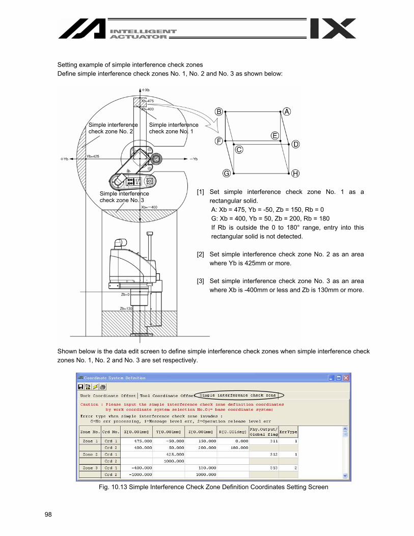
98
Setting example of simple interference check zones Define simple interference check zones No. 1, No. 2 and No. 3 as shown below:
Shown below is the data edit screen to define simple interference check zones when simple interference check zones No. 1, No. 2 and No. 3 are set respectively.
Fig. 10.13 Simple Interference Check Zone Definition Coordinates Setting Screen
Simple interference check zone No. 1
[1] Set simple interference check zone No. 1 as a rectangular solid. A: Xb = 475, Yb = -50, Zb = 150, Rb = 0 G: Xb = 400, Yb = 50, Zb = 200, Rb = 180 If Rb is outside the 0 to 180° range, entry into this rectangular solid is not detected.
[2] Set simple interference check zone No. 2 as an area
where Yb is 425mm or more. [3] Set simple interference check zone No. 3 as an area
where Xb is -400mm or less and Zb is 130mm or more.
Simple interference check zone No. 2
Simple interference check zone No. 3
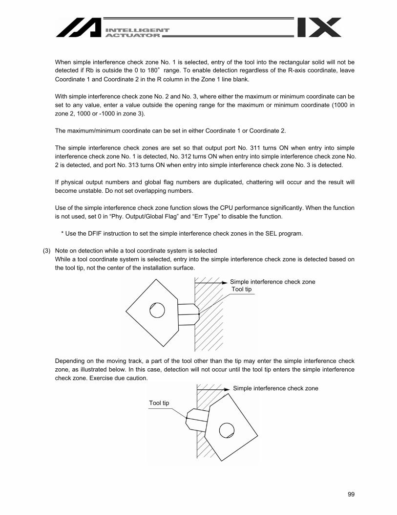
99
When simple interference check zone No. 1 is selected, entry of the tool into the rectangular solid will not be detected if Rb is outside the 0 to 180°range. To enable detection regardless of the R-axis coordinate, leave Coordinate 1 and Coordinate 2 in the R column in the Zone 1 line blank. With simple interference check zone No. 2 and No. 3, where either the maximum or minimum coordinate can be set to any value, enter a value outside the opening range for the maximum or minimum coordinate (1000 in zone 2, 1000 or -1000 in zone 3). The maximum/minimum coordinate can be set in either Coordinate 1 or Coordinate 2. The simple interference check zones are set so that output port No. 311 turns ON when entry into simple interference check zone No. 1 is detected, No. 312 turns ON when entry into simple interference check zone No. 2 is detected, and port No. 313 turns ON when entry into simple interference check zone No. 3 is detected. If physical output numbers and global flag numbers are duplicated, chattering will occur and the result will become unstable. Do not set overlapping numbers. Use of the simple interference check zone function slows the CPU performance significantly. When the function is not used, set 0 in “Phy. Output/Global Flag” and “Err Type” to disable the function.
* Use the DFIF instruction to set the simple interference check zones in the SEL program.
(3) Note on detection while a tool coordinate system is selected While a tool coordinate system is selected, entry into the simple interference check zone is detected based on the tool tip, not the center of the installation surface.
Depending on the moving track, a part of the tool other than the tip may enter the simple interference check zone, as illustrated below. In this case, detection will not occur until the tool tip enters the simple interference check zone. Exercise due caution.
Simple interference check zone Tool tip
Simple interference check zone
Tool tip

100
10.5 Coordinate System Definition Data Clear Window The procedure to delete coordinate system definition data is explained below: [1] Click Coordinate System (D) from the menu bar, and then select Clear (L). [2] The coordinate system definition data clear window will be displayed.
Fig. 10.14 Coordinate System Definition Data Clear
Deletion of Coordinate Definition Data Select the type of coordinate system data you wish to delete. Next, click the OK button. A warning message will be displayed to confirm if you really want to delete the data. Click the OK button. The data will be transferred to the controller. Clicking the Cancel button will cancel the operation.
Fig. 10.15 Warning
[3] Write to the flash ROM.
Fig. 10.16 Confirmation
Click Yes → The memory data will be written to the flash ROM.
Click No → The memory data will not be written to the flash ROM. Perform a reset (reconnect the power or reset the software), and the robot will return to the condition before the deletion.
Click in the applicable checkbox to select the type of data you wish to delete.
Click in the applicable checkbox to select the type of data you wish to write.

101
10.6 Printing of Coordinate System Definition Data The procedure to print coordinate system definition data is explained below. [1] Click the [X] button in the menu if the coordinate system data definition edit window. [2] Select whether to print all types or the coordinate system data being displayed.
Fig. 10.17 Print Type Selection
[3] The coordinate system definition data will be printed in accordance with the selected content.
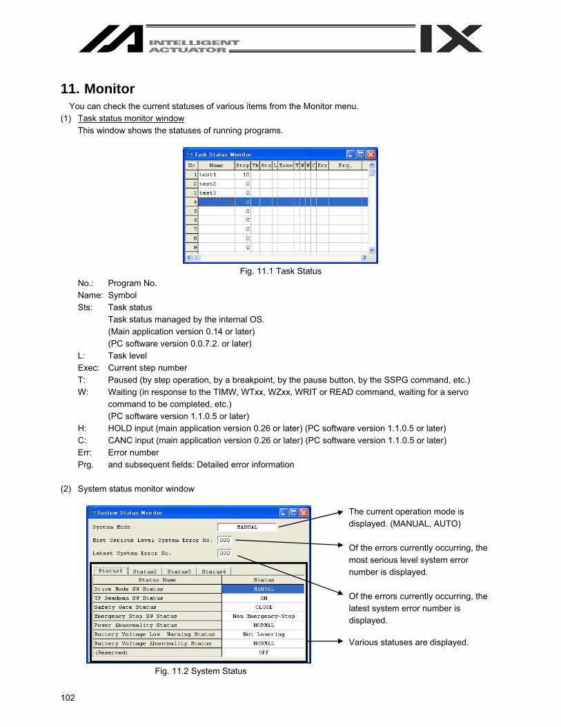
102
11. Monitor You can check the current statuses of various items from the Monitor menu.
(1) Task status monitor window This window shows the statuses of running programs.
Fig. 11.1 Task Status
No.: Program No. Name: Symbol Sts: Task status
Task status managed by the internal OS. (Main application version 0.14 or later) (PC software version 0.0.7.2. or later)
L: Task level Exec: Current step number T: Paused (by step operation, by a breakpoint, by the pause button, by the SSPG command, etc.) W: Waiting (in response to the TIMW, WTxx, WZxx, WRIT or READ command, waiting for a servo
command to be completed, etc.) (PC software version 1.1.0.5 or later)
H: HOLD input (main application version 0.26 or later) (PC software version 1.1.0.5 or later) C: CANC input (main application version 0.26 or later) (PC software version 1.1.0.5 or later) Err: Error number Prg. and subsequent fields: Detailed error information
(2) System status monitor window
Fig. 11.2 System Status
The current operation mode is displayed. (MANUAL, AUTO) Of the errors currently occurring, the most serious level system error number is displayed. Of the errors currently occurring, the latest system error number is displayed. Various statuses are displayed.

103
In the case of the SSEL, ASEL or PSEL controller, the Status of Positioner Mode can be checked by Status 3.
Fig. 11.3 Display in Program Mode Fig. 11.4 Display in Positioner Mode
(3) Axis status monitor window
This window shows the status of each axis.
Fig. 11.5 Axis Status

104
(4) Input port, virtual input port, output port and virtual output port windows
These windows show the ON/OFF status of each input/output. 1: ON, 0: OFF
Fig. 11.6 Input/Output Ports
The 1/0 (ON/OFF) of output ports and virtual output ports can be switched by double-clicking the applicable port or pressing the Ctrl key and space key simultaneously. In the case of the SSEL, ASEL or PSL controller in the positioner mode, no symbol will be displayed.
Fig. 11.7 Input/Output Ports (No Symbol)
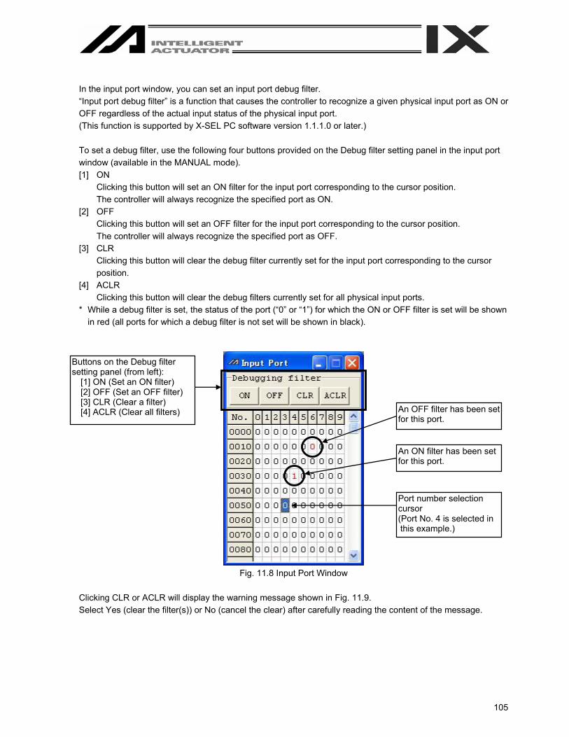
105
In the input port window, you can set an input port debug filter. “Input port debug filter” is a function that causes the controller to recognize a given physical input port as ON or OFF regardless of the actual input status of the physical input port. (This function is supported by X-SEL PC software version 1.1.1.0 or later.) To set a debug filter, use the following four buttons provided on the Debug filter setting panel in the input port window (available in the MANUAL mode). [1] ON
Clicking this button will set an ON filter for the input port corresponding to the cursor position. The controller will always recognize the specified port as ON.
[2] OFF Clicking this button will set an OFF filter for the input port corresponding to the cursor position. The controller will always recognize the specified port as OFF.
[3] CLR Clicking this button will clear the debug filter currently set for the input port corresponding to the cursor position.
[4] ACLR Clicking this button will clear the debug filters currently set for all physical input ports.
* While a debug filter is set, the status of the port (“0” or “1”) for which the ON or OFF filter is set will be shown in red (all ports for which a debug filter is not set will be shown in black).
Fig. 11.8 Input Port Window
Clicking CLR or ACLR will display the warning message shown in Fig. 11.9. Select Yes (clear the filter(s)) or No (cancel the clear) after carefully reading the content of the message.
Buttons on the Debug filter setting panel (from left):
[1] ON (Set an ON filter) [2] OFF (Set an OFF filter) [3] CLR (Clear a filter) [4] ACLR (Clear all filters) An OFF filter has been set
for this port.
An ON filter has been set for this port.
Port number selection cursor (Port No. 4 is selected in this example.)
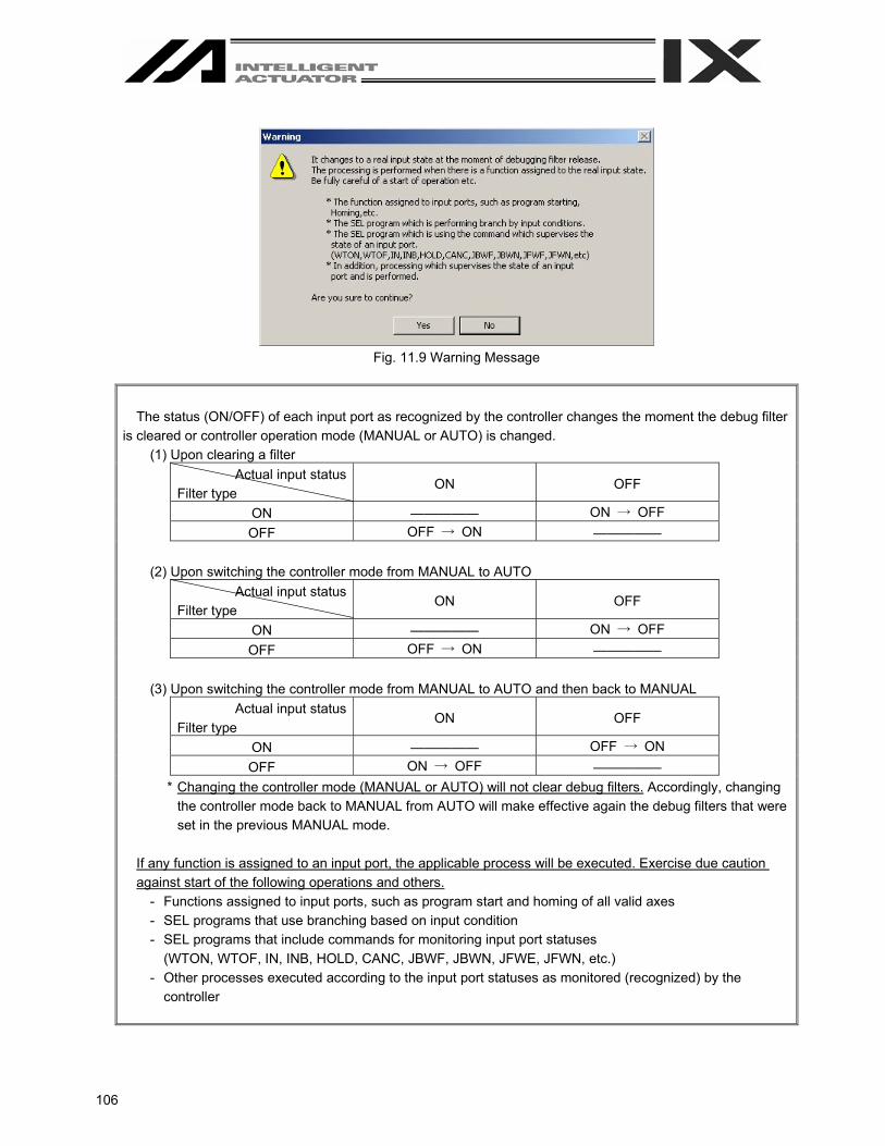
106
Fig. 11.9 Warning Message
The status (ON/OFF) of each input port as recognized by the controller changes the moment the debug filter is cleared or controller operation mode (MANUAL or AUTO) is changed.
(1) Upon clearing a filter Actual input status
Filter type ON OFF
ON ————— ON → OFF OFF OFF → ON —————
(2) Upon switching the controller mode from MANUAL to AUTO
Actual input status Filter type
ON OFF
ON ————— ON → OFF OFF OFF → ON —————
(3) Upon switching the controller mode from MANUAL to AUTO and then back to MANUAL
Actual input status Filter type
ON OFF
ON ————— OFF → ON OFF ON → OFF —————
* Changing the controller mode (MANUAL or AUTO) will not clear debug filters. Accordingly, changing the controller mode back to MANUAL from AUTO will make effective again the debug filters that were set in the previous MANUAL mode.
If any function is assigned to an input port, the applicable process will be executed. Exercise due caution against start of the following operations and others.
- Functions assigned to input ports, such as program start and homing of all valid axes - SEL programs that use branching based on input condition - SEL programs that include commands for monitoring input port statuses
(WTON, WTOF, IN, INB, HOLD, CANC, JBWF, JBWN, JFWE, JFWN, etc.) - Other processes executed according to the input port statuses as monitored (recognized) by the
controller

107
(5) Global flag, global integer variable, global real variable and global string windows
Fig. 11.10 Global
You can change the values in global variables or assign values to global variables. You can also change the characters in global strings or assign characters to global strings. The 1/0 (ON/OFF) of global flags can be switched by double-clicking the applicable global flag or pressing the Ctrl key and space key simultaneously. In the integer variable monitor, select Decimal or Hexadecimal for the data radix. (Select it from the combo box at the top of the window.)
Fig. 11.11 Decimal Notation Fig. 11.12 Hexadecimal Notation

108
(6) Detailed error information
Clicking Monitor (M) from the main menu and then selecting Detailed Error Information (E) will display the Error Number Select screen. Clicking OK after setting the Error Number Select will display the Detailed Error Information screen.
Fig. 11.13 Error Number Select Screen
When errors occur, error codes, messages and other information will be displayed.
Save the error list in a file. (CSV format)* Print the error list.
Update the error list to the latest one. Clear the error list.
The smaller the number is, the more recently the error occurred. Error code
Error message Time after controller power reconnection or software reset
Fig. 11.14 Detailed Error Information
Program No.
Step No.
Axis No.
Position No.
Info. 1 to Info. 4 is information for our company to analyze error causes. (The contents vary depending on the error No )
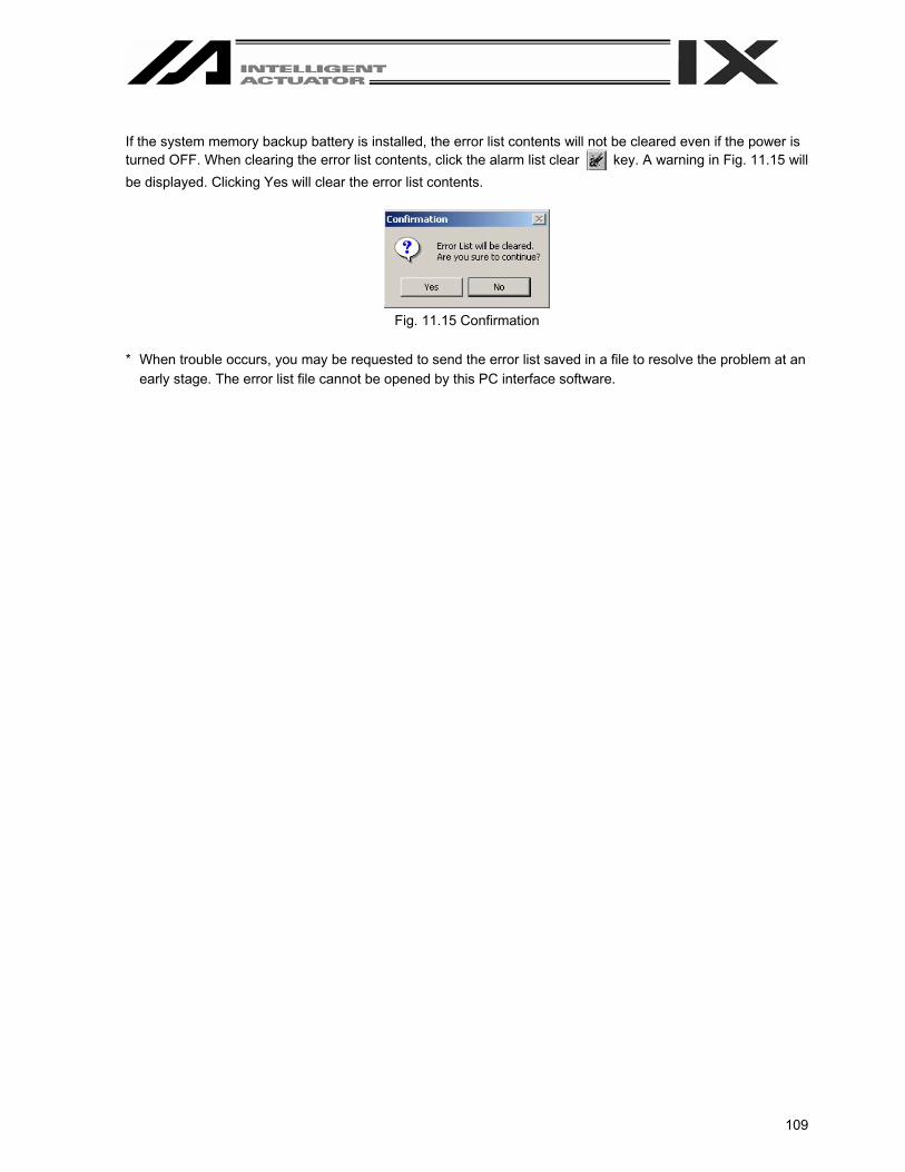
109
If the system memory backup battery is installed, the error list contents will not be cleared even if the power is turned OFF. When clearing the error list contents, click the alarm list clear key. A warning in Fig. 11.15 will be displayed. Clicking Yes will clear the error list contents.
Fig. 11.15 Confirmation
* When trouble occurs, you may be requested to send the error list saved in a file to resolve the problem at an
early stage. The error list file cannot be opened by this PC interface software.
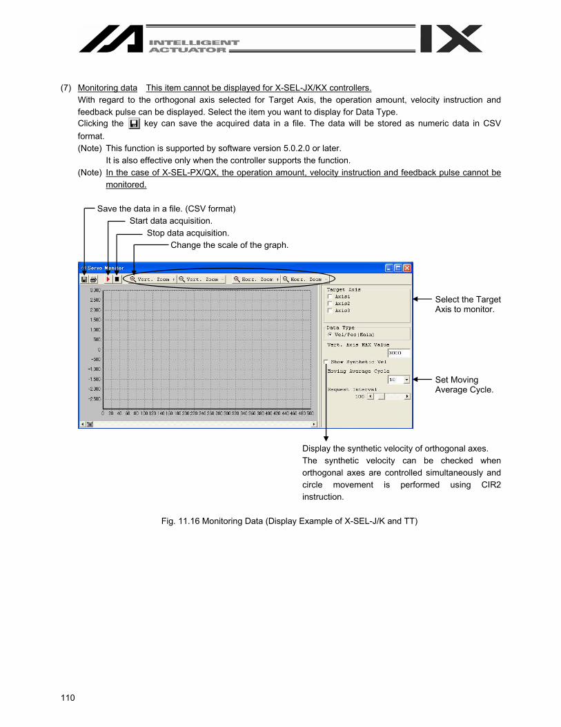
110
(7) Monitoring data This item cannot be displayed for X-SEL-JX/KX controllers.
With regard to the orthogonal axis selected for Target Axis, the operation amount, velocity instruction and feedback pulse can be displayed. Select the item you want to display for Data Type. Clicking the key can save the acquired data in a file. The data will be stored as numeric data in CSV format. (Note) This function is supported by software version 5.0.2.0 or later.
It is also effective only when the controller supports the function. (Note) In the case of X-SEL-PX/QX, the operation amount, velocity instruction and feedback pulse cannot be
monitored.
Save the data in a file. (CSV format) Start data acquisition.
Stop data acquisition. Change the scale of the graph.
Display the synthetic velocity of orthogonal axes. The synthetic velocity can be checked when orthogonal axes are controlled simultaneously and circle movement is performed using CIR2 instruction.
Fig. 11.16 Monitoring Data (Display Example of X-SEL-J/K and TT)
Select the Target Axis to monitor.
Set Moving Average Cycle.

111
Save the data in a file. (CSV format)
Start data acquisition. Stop data acquisition.
Change the scale of the graph.
Display the synthetic velocity of orthogonal axes. The synthetic velocity can be checked when orthogonal axes are controlled simultaneously and circle movement is performed using CIR2 instruction.
Fig. 11.17 Monitoring Data (Display Example of X-SEL-P/Q (Orthogonal axes) and PX/QX)
Select the Target Axis to monitor.

112
Save the data in a file. (CSV format)
Start data acquisition. Stop data acquisition.
Change the scale of the graph.
Display the synthetic velocity of orthogonal axes. The synthetic velocity can be checked when orthogonal axes are controlled simultaneously and circle movement is performed using CIR2 instruction.
Fig. 11.18 Monitoring Data (Display Example of SSEL, ASEL and PSEL)
Select the Target Axis to monitor.
Buffering indicates the sampling number. The cycle of one sample can be set with “Other Parameter No. 51.”

113
12. How to Reset an Absolute Encoder 12.1 Orthogonal axis
If the voltage of the absolute-encoder backup battery in the X-SEL controller becomes low or after the battery or encoder cable has been disconnected, an encoder battery error will occur. In this case, the absolute encoder must be reset. (1) Click Controller (C) from the menu bar, and then select Absolute Reset (A).
In the case of the X-SEL-PX/QX controller, select Abs. Encoder Reset (Orthogonal axis) (A). (2) When the following warning window appears, click OK.
Fig. 12.1 Warning
(3) The Abs. Encoder Reset window will open. Click here to select the axis you want to execute an absolute
encoder reset for.
Fig. 11.1 Absolute Reset
(4) Clicking Encoder Rotation Data Reset1 will display the following warning window. Click Yes.
Fig. 11.3 Warning
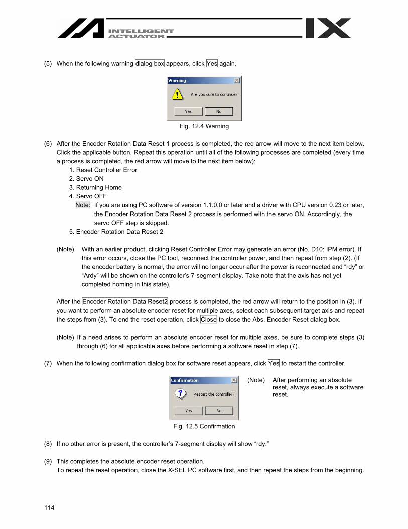
114
(5) When the following warning dialog box appears, click Yes again.
Fig. 12.4 Warning
(6) After the Encoder Rotation Data Reset 1 process is completed, the red arrow will move to the next item below.
Click the applicable button. Repeat this operation until all of the following processes are completed (every time a process is completed, the red arrow will move to the next item below):
1. Reset Controller Error 2. Servo ON 3. Returning Home 4. Servo OFF
Note: If you are using PC software of version 1.1.0.0 or later and a driver with CPU version 0.23 or later, the Encoder Rotation Data Reset 2 process is performed with the servo ON. Accordingly, the servo OFF step is skipped.
5. Encoder Rotation Data Reset 2
(Note) With an earlier product, clicking Reset Controller Error may generate an error (No. D10: IPM error). If this error occurs, close the PC tool, reconnect the controller power, and then repeat from step (2). (If the encoder battery is normal, the error will no longer occur after the power is reconnected and “rdy” or “Ardy” will be shown on the controller’s 7-segment display. Take note that the axis has not yet completed homing in this state).
After the Encoder Rotation Data Reset2 process is completed, the red arrow will return to the position in (3). If you want to perform an absolute encoder reset for multiple axes, select each subsequent target axis and repeat the steps from (3). To end the reset operation, click Close to close the Abs. Encoder Reset dialog box. (Note) If a need arises to perform an absolute encoder reset for multiple axes, be sure to complete steps (3)
through (6) for all applicable axes before performing a software reset in step (7). (7) When the following confirmation dialog box for software reset appears, click Yes to restart the controller.
Fig. 12.5 Confirmation
(8) If no other error is present, the controller’s 7-segment display will show “rdy.” (9) This completes the absolute encoder reset operation.
To repeat the reset operation, close the X-SEL PC software first, and then repeat the steps from the beginning.
(Note) After performing an absolute reset, always execute a software reset.
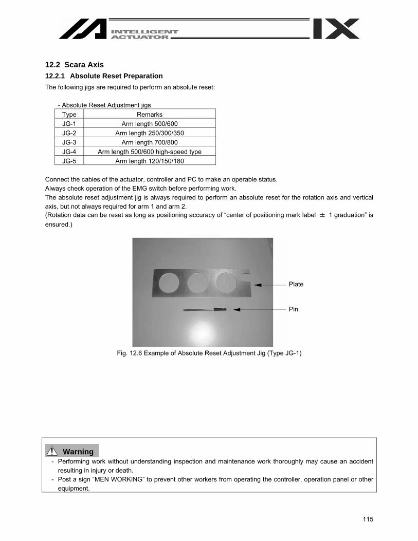
115
12.2 Scara Axis 12.2.1 Absolute Reset Preparation The following jigs are required to perform an absolute reset:
- Absolute Reset Adjustment jigs Type Remarks JG-1 Arm length 500/600 JG-2 Arm length 250/300/350 JG-3 Arm length 700/800 JG-4 Arm length 500/600 high-speed type JG-5 Arm length 120/150/180
Connect the cables of the actuator, controller and PC to make an operable status. Always check operation of the EMG switch before performing work. The absolute reset adjustment jig is always required to perform an absolute reset for the rotation axis and vertical axis, but not always required for arm 1 and arm 2. (Rotation data can be reset as long as positioning accuracy of “center of positioning mark label ± 1 graduation” is ensured.)
Fig. 12.6 Example of Absolute Reset Adjustment Jig (Type JG-1)
Warning - Performing work without understanding inspection and maintenance work thoroughly may cause an accident
resulting in injury or death. - Post a sign “MEN WORKING” to prevent other workers from operating the controller, operation panel or other
equipment.
Plate
Pin

116
12.2.2 Starting the Absolute Reset Menu (1) Open the Abs. Encoder Reset window from PC software.
(Note) In the case of X-SEL-PX/QX, select Abs. Encoder Reset (Scara Axis) (Y).
Fig. 12.7 Opening Operation of Abs. Encoder Reset Window (2) The Abs. Encoder Reset window will open.
- One of three Abs. Encoder Reset screens - for Arm1 (A1c), Arm2 (A2c), Rot. Axis (Rc) + Vert. Axis (Zc) - is displayed when a corresponding tab is clicked.
Fig. 12.8 Abs. Encoder Reset Window
Abs. Encoder Reset Screen for Arm 1/Arm 2
Abs. Encoder Reset Screen for Rotation Axis + Vertical Axis
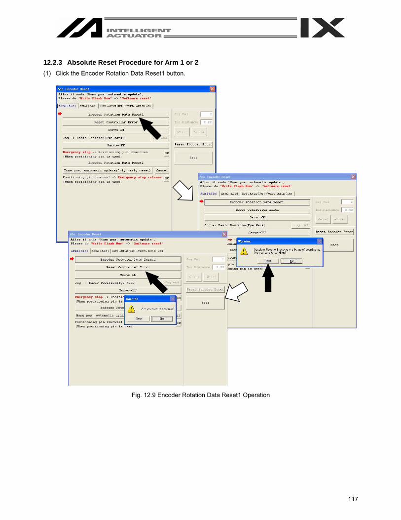
117
12.2.3 Absolute Reset Procedure for Arm 1 or 2 (1) Click the Encoder Rotation Data Reset1 button.
Fig. 12.9 Encoder Rotation Data Reset1 Operation
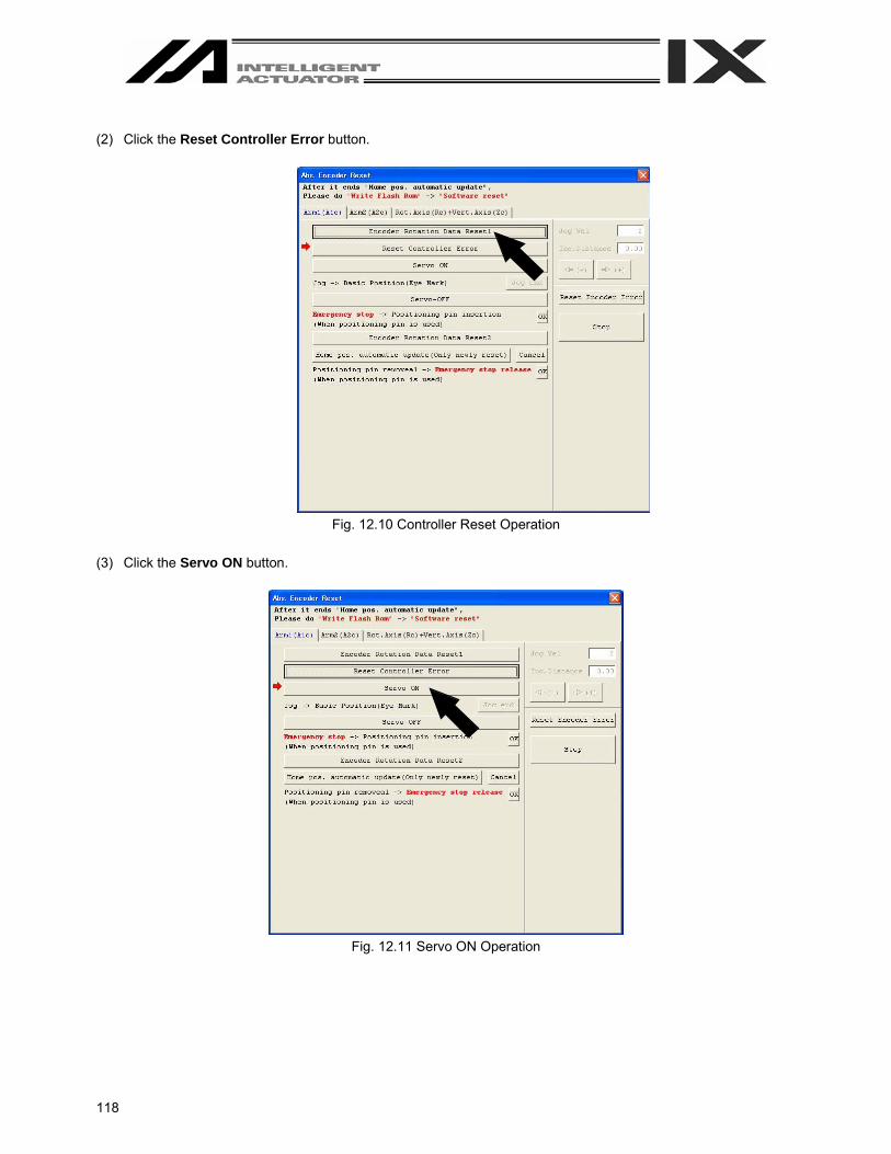
118
(2) Click the Reset Controller Error button.
Fig. 12.10 Controller Reset Operation
(3) Click the Servo ON button.
Fig. 12.11 Servo ON Operation

119
(4) Jog the arm to near the reference position (see reference position drawing in step 7), and click the Jog end
button.
Fig. 12.12 Jog Operation
(5) Click the Servo-Off button.
Fig. 12.13 Servo-OFF Operation
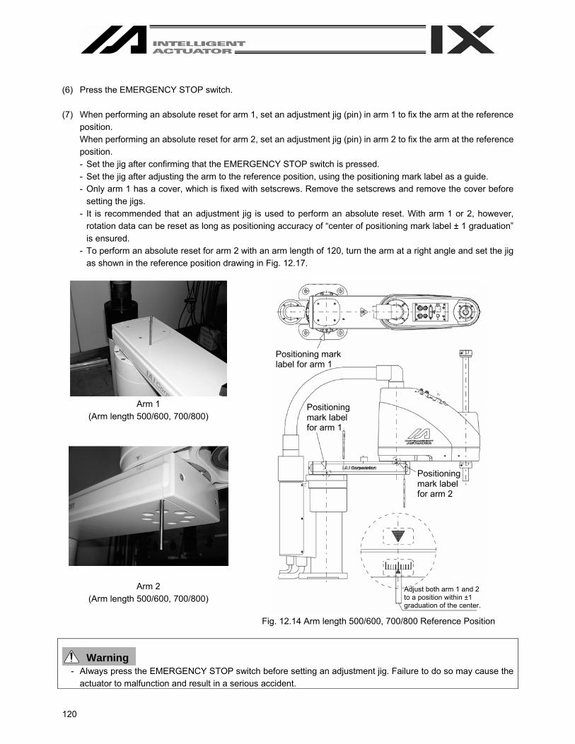
120
(6) Press the EMERGENCY STOP switch. (7) When performing an absolute reset for arm 1, set an adjustment jig (pin) in arm 1 to fix the arm at the reference
position. When performing an absolute reset for arm 2, set an adjustment jig (pin) in arm 2 to fix the arm at the reference position. - Set the jig after confirming that the EMERGENCY STOP switch is pressed. - Set the jig after adjusting the arm to the reference position, using the positioning mark label as a guide. - Only arm 1 has a cover, which is fixed with setscrews. Remove the setscrews and remove the cover before
setting the jigs. - It is recommended that an adjustment jig is used to perform an absolute reset. With arm 1 or 2, however,
rotation data can be reset as long as positioning accuracy of “center of positioning mark label ± 1 graduation” is ensured.
- To perform an absolute reset for arm 2 with an arm length of 120, turn the arm at a right angle and set the jig as shown in the reference position drawing in Fig. 12.17.
Arm 1
(Arm length 500/600, 700/800)
Arm 2 (Arm length 500/600, 700/800)
Fig. 12.14 Arm length 500/600, 700/800 Reference Position
Warning - Always press the EMERGENCY STOP switch before setting an adjustment jig. Failure to do so may cause the
actuator to malfunction and result in a serious accident.
Positioning mark label for arm 1
Positioning mark label for arm 1
Positioning mark label for arm 2
Adjust both arm 1 and 2 to a position within ±1 graduation of the center.

121
Arm 1
(Arm length 250/300/350)
Arm 2 (Arm length 250/300/350)
Fig. 12.15 Arm length 250/300/350 Reference Position
(Note) When performing an absolute reset for arm 1 of IX-NNN2515, rotate arm 2 slightly then set with an adjustment jig (pin) to set it.
Warning - Always press the EMERGENCY STOP switch before setting an adjustment jig. Failure to do so may cause the
actuator to malfunction and result in a serious accident.
Positioning mark label for arm 1
Positioning mark label for arm 2
Inse
rtion
dep
th: A
ppro
x. 6
0 m
m
Inse
rtion
dep
th: A
ppro
x. 2
0 m
m
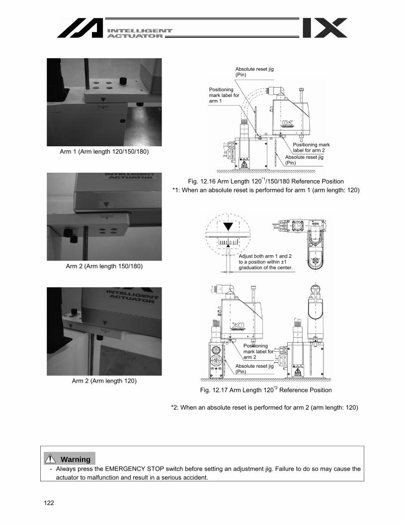
122
Arm 1 (Arm length 120/150/180)
Arm 2 (Arm length 150/180)
Arm 2 (Arm length 120)
Fig. 12.16 Arm Length 120*1/150/180 Reference Position
*1: When an absolute reset is performed for arm 1 (arm length: 120)
Fig. 12.17 Arm Length 120*2 Reference Position
*2: When an absolute reset is performed for arm 2 (arm length: 120)
Warning - Always press the EMERGENCY STOP switch before setting an adjustment jig. Failure to do so may cause the
actuator to malfunction and result in a serious accident.
Positioning mark label for arm 1
Adjust both arm 1 and 2 to a position within ±1 graduation of the center.
Absolute reset jig (Pin)
Absolute reset jig (Pin)
Positioning mark label for arm 2
Positioning mark label for arm 2
Absolute reset jig (Pin)
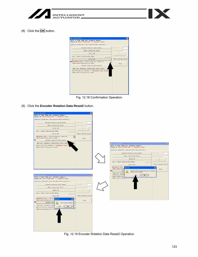
123
(8) Click the OK button.
Fig. 12.18 Confirmation Operation
(9) Click the Encoder Rotation Data Reset2 button.
Fig. 12.19 Encoder Rotation Data Reset2 Operation
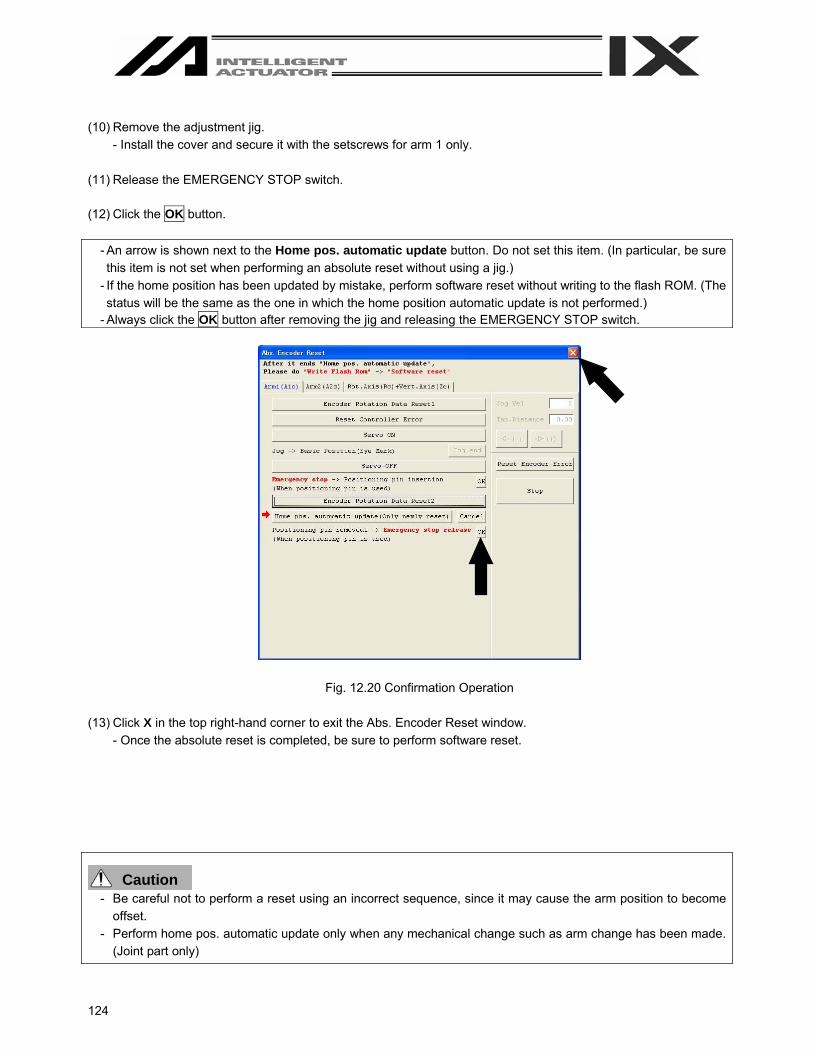
124
(10) Remove the adjustment jig.
- Install the cover and secure it with the setscrews for arm 1 only. (11) Release the EMERGENCY STOP switch. (12) Click the OK button.
- An arrow is shown next to the Home pos. automatic update button. Do not set this item. (In particular, be sure this item is not set when performing an absolute reset without using a jig.)
- If the home position has been updated by mistake, perform software reset without writing to the flash ROM. (The status will be the same as the one in which the home position automatic update is not performed.)
- Always click the OK button after removing the jig and releasing the EMERGENCY STOP switch.
Fig. 12.20 Confirmation Operation (13) Click X in the top right-hand corner to exit the Abs. Encoder Reset window.
- Once the absolute reset is completed, be sure to perform software reset.
Caution - Be careful not to perform a reset using an incorrect sequence, since it may cause the arm position to become
offset. - Perform home pos. automatic update only when any mechanical change such as arm change has been made.
(Joint part only)

125
12.2.4 Absolute Reset Procedure for Rotation Axis + Vertical Axis (1) Click the Encoder Rotation Data Reset1 button.
Fig. 12.21 Encoder Rotation Data Reset1 Operation
(2) Click the Reset Controller Error button.
Fig. 12.22 Reset Controller Error Operation
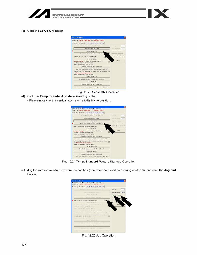
126
(3) Click the Servo ON button.
Fig. 12.23 Servo ON Operation
(4) Click the Temp. Standard posture standby button. - Please note that the vertical axis returns to its home position.
Fig. 12.24 Temp. Standard Posture Standby Operation
(5) Jog the rotation axis to the reference position (see reference position drawing in step 8), and click the Jog end
button.
Fig. 12.25 Jog Operation

127
(6) Click the Servo-OFF button.
Fig. 12.26 Servo-OFF Operation
(7) Press the EMERGENCY STOP switch. (8) Affix the rotation axis at the reference position by setting the plate and pin of the adjustment jig as illustrated
below. - Set the jig after confirming that the EMERGENCY STOP switch is pressed. - Set the jig using the positioning mark as a guide. - The top face of the stopper should roughly align with the bottom face of arm 2.
Fig. 12.27 Arm Length 500/600, 700/800 Reference Position
Warning - Always press the EMERGENCY STOP switch before setting an adjustment jig. Failure to do so may cause the
actuator to malfunction and result in a serious accident. - Pay attention to the orientation of the D-cut surface of the plate jig.
Positioning mark label for rotation axis
D-cut surface
The top face of the stopper should align with the bottom face of arm 2.
The plate and pin should make light contact.
(Bottom view) D-cut surface

128
Fig. 12.28 Arm Length 250/300/350 Reference Position
Warning - Always press the EMERGENCY STOP switch before setting an adjustment jig. Failure to do so may cause the
actuator to malfunction and result in a serious accident.
The top face of the stopper should align with the bottom face of arm 2 so that clearance will be approx. 4 mm.
Contact the jig with the pin lightly.
D-cut surface
D-cut surface
Positioning mark label for rotation axis
(Bottom view)
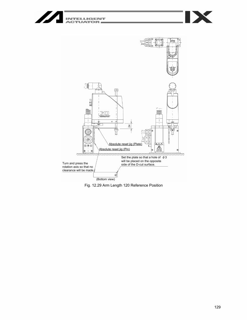
129
Fig. 12.29 Arm Length 120 Reference Position
Absolute reset jig (Plate)
Absolute reset jig (Pin)
Turn and press the rotation axis so that no clearance will be made.
Set the plate so that a hole of φ3 will be placed on the opposite side of the D-cut surface.
(Bottom view)
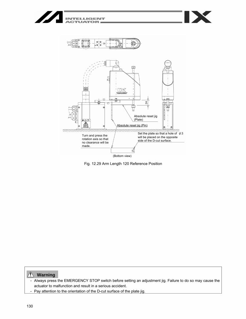
130
Fig. 12.29 Arm Length 120 Reference Position
Warning - Always press the EMERGENCY STOP switch before setting an adjustment jig. Failure to do so may cause the
actuator to malfunction and result in a serious accident. - Pay attention to the orientation of the D-cut surface of the plate jig.
Absolute reset jig (Plate)
Absolute reset jig (Pin)
Turn and press the rotation axis so that no clearance will be made.
Set the plate so that a hole of φ3 will be placed on the opposite side of the D-cut surface.
(Bottom view)

131
(9) Click the OK button.
Fig. 12.31 Confirmation Operation
(10) Click the Encoder Rotation Data Reset2 button.
Fig. 12.32 Encoder Rotation Data Reset2 Operation
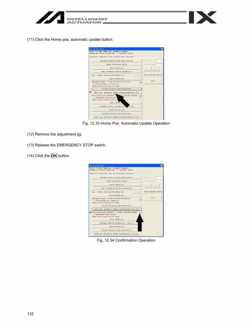
132
(11) Click the Home pos. automatic update button.
Fig. 12.33 Home Pos. Automatic Update Operation
(12) Remove the adjustment jig. (13) Release the EMERGENCY STOP switch. (14) Click the OK button.
Fig. 12.34 Confirmation Operation
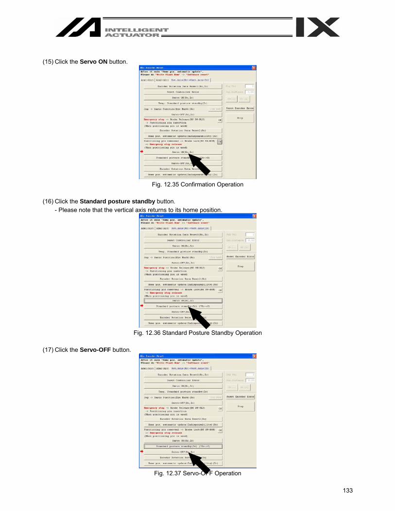
133
(15) Click the Servo ON button.
Fig. 12.35 Confirmation Operation
(16) Click the Standard posture standby button.
- Please note that the vertical axis returns to its home position.
Fig. 12.36 Standard Posture Standby Operation
(17) Click the Servo-OFF button.
Fig. 12.37 Servo-OFF Operation
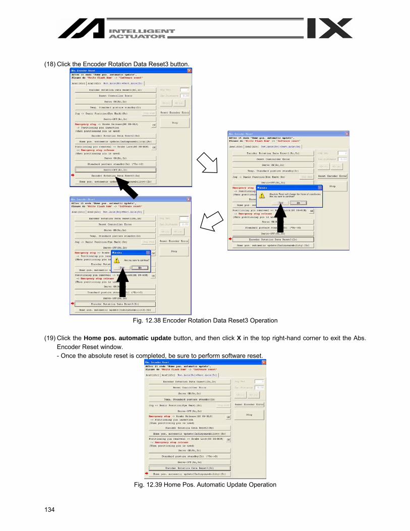
134
(18) Click the Encoder Rotation Data Reset3 button.
Fig. 12.38 Encoder Rotation Data Reset3 Operation
(19) Click the Home pos. automatic update button, and then click X in the top right-hand corner to exit the Abs.
Encoder Reset window. - Once the absolute reset is completed, be sure to perform software reset.
Fig. 12.39 Home Pos. Automatic Update Operation

135
13. Supplemental Information on Controller Menu Items 13.1 Software Reset
Selecting this menu item will restart the controller. Caution is required because data that is not yet written to the flash ROM will be lost after this operation. Click Controller (C) from the menu bar, and then select Software Reset (R).
13.2 Reset Error
Selecting this menu item will reset message level errors and operation-cancellation level errors. Even after selecting Reset Error, those errors whose cause has not been removed will occur again. Click Controller (C) from the menu bar, and then select Reset Error (E).

136
13.3. Drive-source Recovery Request and Operation-pause Reset Request 13.3.1 In the cases of Controllers Other Than SSEL, ASEL or PSEL Controllers (1) Drive-source recovery request
[1] How to issue a drive-source recovery request A drive-source recovery request is required only in the following case: - When you set I/O parameter No.44 to 1, drive power cut-off occurs. - > Recovery after the main cause of
cut-off is solved.
[2] How to issue a drive-source recovery request A drive-source recovery request can be issued using one of the following methods: - Set I/O parameter No.44 to 1 (input selection function 014 = Drive-source cut-off reset input), and then
input the ON edge on input port No. 14 - From the software menu, execute Controller (C) - > Request Drive Power Recovery (P).
(2) Operation pause release request
[1] Case where an operation pause release request is required An operation pause release request is required in any of the following cases: - When you set other parameter No.9 to 2, (Deadman SW recovery release according to type = continuous
operation release [during automatic operation only], stop according to Deadman SW during automatic operation - > recovery after release stop (operation pause release).
- When you set other parameter No.10 to 2, (emergency stop recovery according to type = continuous operation recovery during automatic operation only), emergency stop during automatic operation - > recovery after emergency stop release (operation pause release).
- When you set other parameter No.11 to 2, (according to recovery type during safety gate open recovery = continuous operation recovery (during automatic operation only), safety gate OPEN during automatic operation - > recovery after safety gate CLOSE (operation pause release).
- When you set I/O parameter No.36 to 1, (input selection function 006 = pausing operation signal), OFF level input on input port No.6 at automatic operation (pausing operation) - > recovery after ON level input on input port No.6 (operation pause release).
[2] How to issue an operation pause release request
An operation pause release request can be issued using one of the following methods: - Set I/O parameter No.35 to 1 (input selection function 005 = operation pause release signal), and then
input the ON edge on input port No.5. - From the software menu, execute Controller (C) - > Request Release Pause (L).
Note) If the case in [2] of (1) and any of the cases in [2] of (2) are present at the same time, a drive-source
recovery request must be issued first, followed by an operation-pause reset request.

137
13.3.2 In the cases of SSEL, ASEL or PSEL Controllers (1) Drive-source recovery request
[1] Case where a drive-source recovery request is required A drive-source recovery request is required only in the following case: - When you specify any input port for the drive power cut-off release input signal (dedicated function), drive
power cut-off occurs. - > recovery after the main cause of cut-off is solved.
[2] How to issue an operation pause release request An operation pause release request can be issued using one of the following methods: - Set the I/O parameter (No.30 - No.45, No.251 - No.258) corresponding to the input port No. to 17
(specified input function value). (Refer to the list of I/O functions and I/O parameters in the SSEL, ASEL or PSEL controller operation manual.) Input the ON edge on the specified input port No.
- From the software menu, execute Controller (C) - > Request Drive Power Recovery (P). (2) Operation pause release request
[1] An operation pause release request is required in any of the following methods: Only the following case requires executing Request Release Pause: - When you set other parameter No.10 to 2, (emergency stop recovery release according to type =
continuous operation release [during automatic operation only], emergency stop during automatic operation - > recovery after release of emergency stop (operation pause release).
- When you set other parameter No.11 to 2, (Deadman SW/Enable SW recovery according to type = continuous operation recovery during automatic operation only), stop by Deadman SW or Enable SW during automatic operation - > recovery after emergency stop release (operation pause release).
- Specify any input port for the operation pause release signal (dedicated function). Set the I/O parameter (No.30 - No.45, No. 251 - No.258) corresponding to the input port No. to 8 (specified input function value). (Refer to the list of I/O functions and I/O parameters.) OFF level input on the input port No. specified at automatic operation (pause operation) - > recovery after ON level input on the input port No. (operation pause release).
[2] How to issue an operation pause release request
An operation pause release request can be issued using one of the following methods: - Specify any input port for the operation pause release signal (dedicated function). Set the I/O parameter
(No.30 - No.45, No.251 - No.258) input port No. corresponding to the input port No. to 7 (specified input function value). (Refer to the list of I/O functions and I/O parameters.) Input the ON edge on the specified input port No.
- From the software menu, execute Controller(C) - > Request Release Pause (L).
Note) If the case in [1] of (1) and any of the cases in [1] of (2) are present at the same time, a drive-source recovery request must be issued first, followed by an operation pause release request.
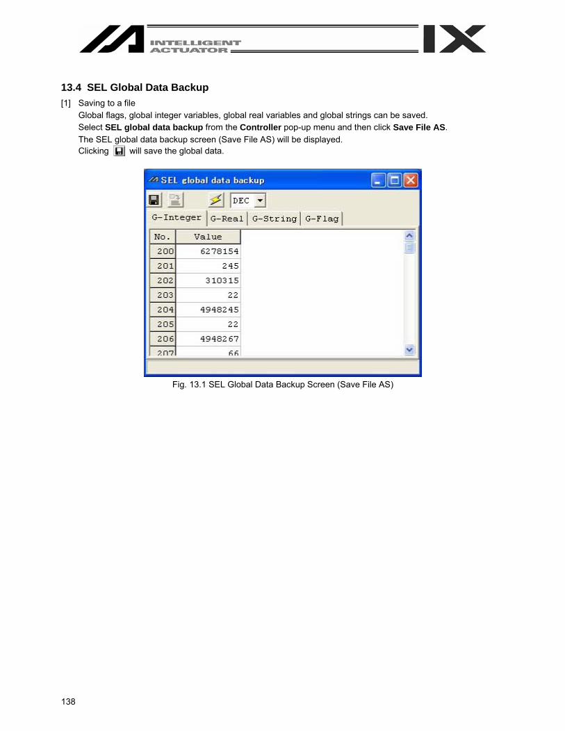
138
13.4 SEL Global Data Backup [1] Saving to a file
Global flags, global integer variables, global real variables and global strings can be saved. Select SEL global data backup from the Controller pop-up menu and then click Save File AS. The SEL global data backup screen (Save File AS) will be displayed. Clicking will save the global data.
Fig. 13.1 SEL Global Data Backup Screen (Save File AS)
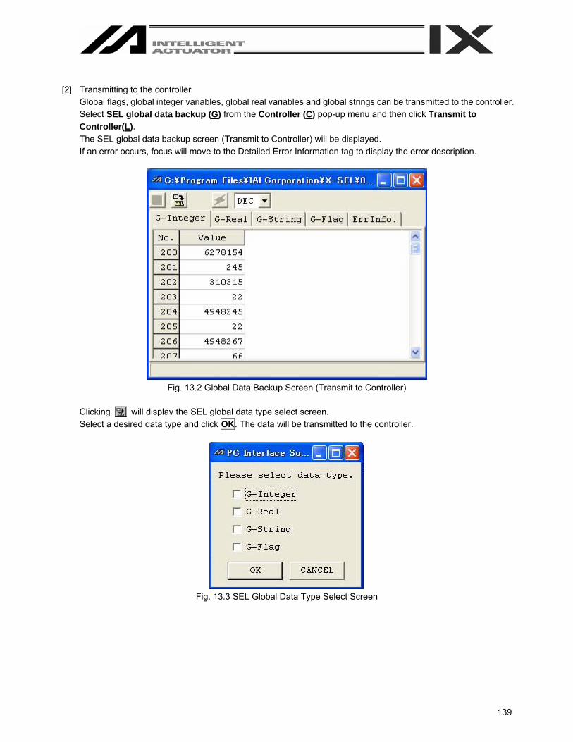
139
[2] Transmitting to the controller
Global flags, global integer variables, global real variables and global strings can be transmitted to the controller. Select SEL global data backup (G) from the Controller (C) pop-up menu and then click Transmit to Controller(L). The SEL global data backup screen (Transmit to Controller) will be displayed. If an error occurs, focus will move to the Detailed Error Information tag to display the error description.
Fig. 13.2 Global Data Backup Screen (Transmit to Controller)
Clicking will display the SEL global data type select screen. Select a desired data type and click OK. The data will be transmitted to the controller.
Fig. 13.3 SEL Global Data Type Select Screen

140
13.5 Control Constant Table Management Information The versions of control constant tables for the encoder and motor can be checked. Select Controller (C) from the menu tool bar and then click Control constant table management information (Z). (Supported by X-SEL-P/Q, PX/QX, SSEL, ASEL and PSEL only.)
Fig. 13.4 Control Constant Table Management Information

141
13.6 Execution Stop of Positioner Mode of SSEL, ASEL or PSEL Controller If you select Execute when the SSEL, ASEL or PSEL controller is in the manual mode and positioner mode, the positioner mode can be executed from your PC. (The 7-segment display will show “PN##.” ## indicates the positioner mode No.) Executing the positioner mode manually enables a test run at safe speed, monitoring of I/O ports and others. Select Positioner Mode (O) from the Controller pop-up menu and then click Execute (E). Pressing the EMERGENCY STOP button or Stop in the screen of Fig. 13.5 will stop the positioner mode. Select Positioner Mode (O) from the Controller pop-up menu and then click Stop (S).
Fig. 13.5 Execue or Stop of Positioner Mode
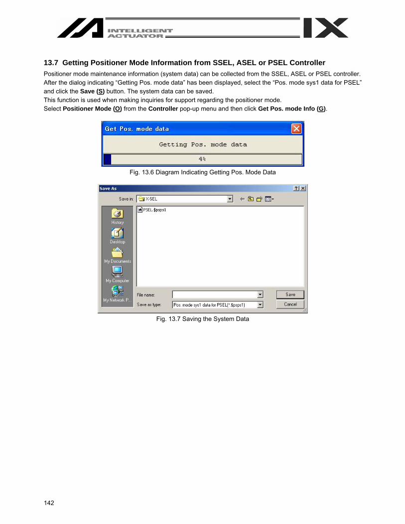
142
13.7 Getting Positioner Mode Information from SSEL, ASEL or PSEL Controller Positioner mode maintenance information (system data) can be collected from the SSEL, ASEL or PSEL controller. After the dialog indicating “Getting Pos. mode data” has been displayed, select the “Pos. mode sys1 data for PSEL” and click the Save (S) button. The system data can be saved. This function is used when making inquiries for support regarding the positioner mode. Select Positioner Mode (O) from the Controller pop-up menu and then click Get Pos. mode Info (G).
Fig. 13.6 Diagram Indicating Getting Pos. Mode Data
Fig. 13.7 Saving the System Data
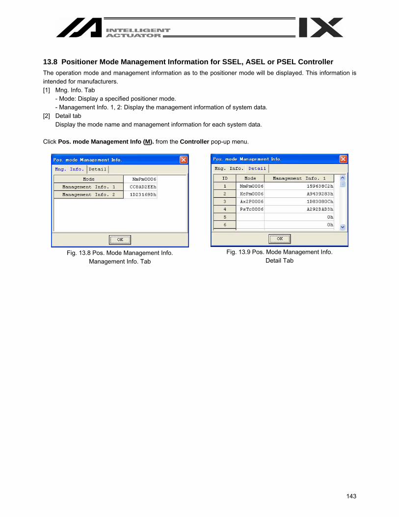
143
13.8 Positioner Mode Management Information for SSEL, ASEL or PSEL Controller The operation mode and management information as to the positioner mode will be displayed. This information is intended for manufacturers. [1] Mng. Info. Tab
- Mode: Display a specified positioner mode. - Management Info. 1, 2: Display the management information of system data.
[2] Detail tab Display the mode name and management information for each system data.
Click Pos. mode Management Info (M). from the Controller pop-up menu.
Fig. 13.8 Pos. Mode Management Info.
Management Info. Tab
Fig. 13.9 Pos. Mode Management Info.
Detail Tab
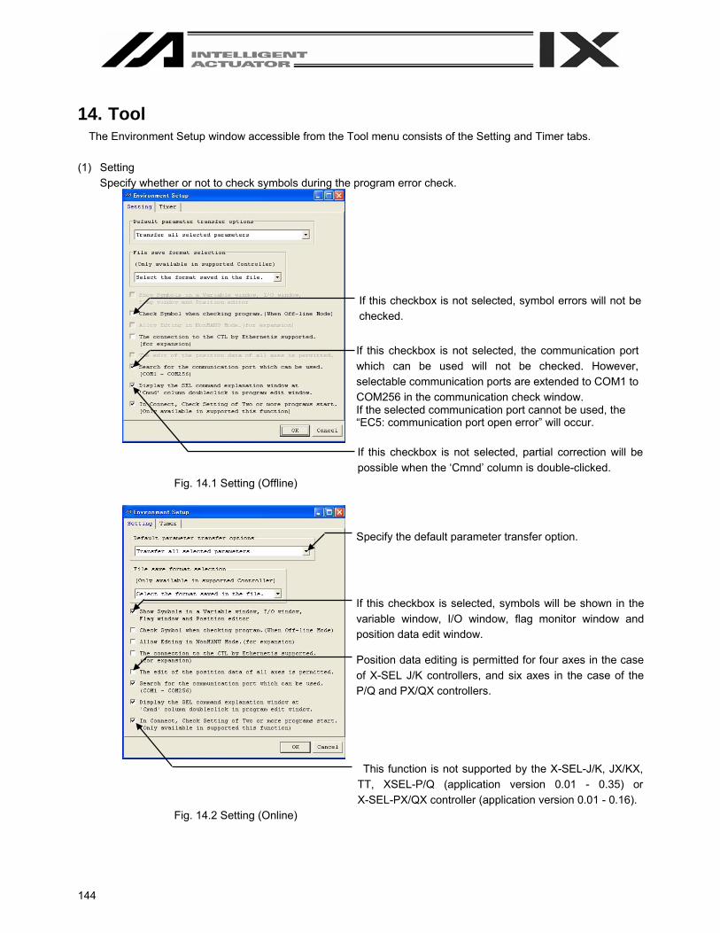
144
14. Tool The Environment Setup window accessible from the Tool menu consists of the Setting and Timer tabs.
(1) Setting
Specify whether or not to check symbols during the program error check.
If this checkbox is not selected, partial correction will be possible when the ‘Cmnd’ column is double-clicked.
Fig. 14.1 Setting (Offline)
This function is not supported by the X-SEL-J/K, JX/KX, TT, XSEL-P/Q (application version 0.01 - 0.35) or X-SEL-PX/QX controller (application version 0.01 - 0.16).
Fig. 14.2 Setting (Online)
If this checkbox is not selected, symbol errors will not be checked.
If this checkbox is not selected, the communication port which can be used will not be checked. However, selectable communication ports are extended to COM1 to COM256 in the communication check window. If the selected communication port cannot be used, the “EC5: communication port open error” will occur.
If this checkbox is selected, symbols will be shown in the variable window, I/O window, flag monitor window and position data edit window.
Specify the default parameter transfer option.
Position data editing is permitted for four axes in the case of X-SEL J/K controllers, and six axes in the case of the P/Q and PX/QX controllers.

145
(2) Timer
You can set the times required for the controller to make reference to the various data. Normally the settings need not be changed.
Fig. 13.3 Timer

146
Appendix Parameter Recovery Method for X-SEL-P/Q and PX/QX Controllers
If parameter data is lost during parameter writing to the flash ROM due to main power OFF or any other factor, all parameters will be rewritten to initial values. In the case of the X-SEL-P/Q or PX/QX controller, an error will be detected after power reconnection or software reset since system-specific settings are lost immediately after parameter initialization. Under such conditions, all parameters cannot be transferred to the controller. The recovery method in that case is explained below. Note: This method is intended to write the parameter data back to the controller for recovery. Please note that
serious effects such as home displacement, inoperability and error occurrence may result when recovery parameters are transferred to any controller other than the target one, even if the model is the same.
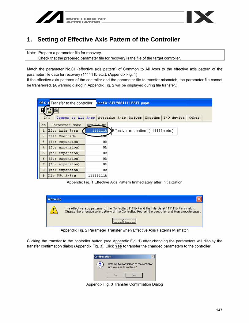
147
1. Setting of Effective Axis Pattern of the Controller Note: Prepare a parameter file for recovery.
Check that the prepared parameter file for recovery is the file of the target controller. Match the parameter No.01 (effective axis pattern) of Common to All Axes to the effective axis pattern of the parameter file data for recovery (111111b etc.). (Appendix Fig. 1) If the effective axis patterns of the controller and the parameter file to transfer mismatch, the parameter file cannot be transferred. (A warning dialog in Appendix Fig. 2 will be displayed during file transfer.)
Appendix Fig. 1 Effective Axis Pattern Immediately after Initialization
Appendix Fig. 2 Parameter Transfer when Effective Axis Patterns Mismatch
Clicking the transfer to the controller button (see Appendix Fig. 1) after changing the parameters will display the transfer confirmation dialog (Appendix Fig. 3). Click Yes to transfer the changed parameters to the controller.
Appendix Fig. 3 Transfer Confirmation Dialog
Transfer to the controller
Effective axis pattern (111111b etc.)

148
Once the transfer has been completed, the flash ROM write confirmation dialog will be displayed (Appendix Fig. 4). After confirming that Parameter is selected, click Yes to write the parameters to the flash ROM.
P/Q Controller PX/QX Controller
Appendix Fig. 4 Flash ROM Write Confirmation Dialog.
Once the parameters have been written to the flash ROM, the software reset confirmation dialog (Appendix Fig. 5) will be displayed. Click Yes to execute software reset.
Appendix Fig. 5 Software Reset Confirmation Dialog
Since the system-specific setting is still lost, an error will be detected after power reconnection or software reset. Even if an error is detected, perform the next step as it is.

149
2. Transfer of Actuator Non-specific Parameters First, open a parameter file for recovery. Clicking the transfer to the controller button will display the Select Parameter Category form.
Appendix Fig. 6 Parameter File Form for Recovery
Transfer to the controller

150
Make settings in the Select Parameter Category form (Appendix Fig. 7) as shown below. [1] Select I/O, Common to All Axes, Other and Manufacturer in the General parameter categories group. [2] Select Transfer all selected parameters under the Select parameter transfer options. [3] Select Controller basic unit dependent parameters transferred under Controller basic unit transmit
options. In the initial condition, Controller basic unit dependent parameters transferred is selected.)
After completing the above settings, click the OK button. Parameter transfer will start.
Appendix. Fig. 7 Transfer of Actuator Non-specific Parameters After performing this procedure, always write the parameters to the flash ROM and reset software. Since the data specific to each axis of the actuator has not been set, an error may be detected after power reconnection or software reset. Even if an error is detected, perform the next step as it is.
(1) (2)
(3)
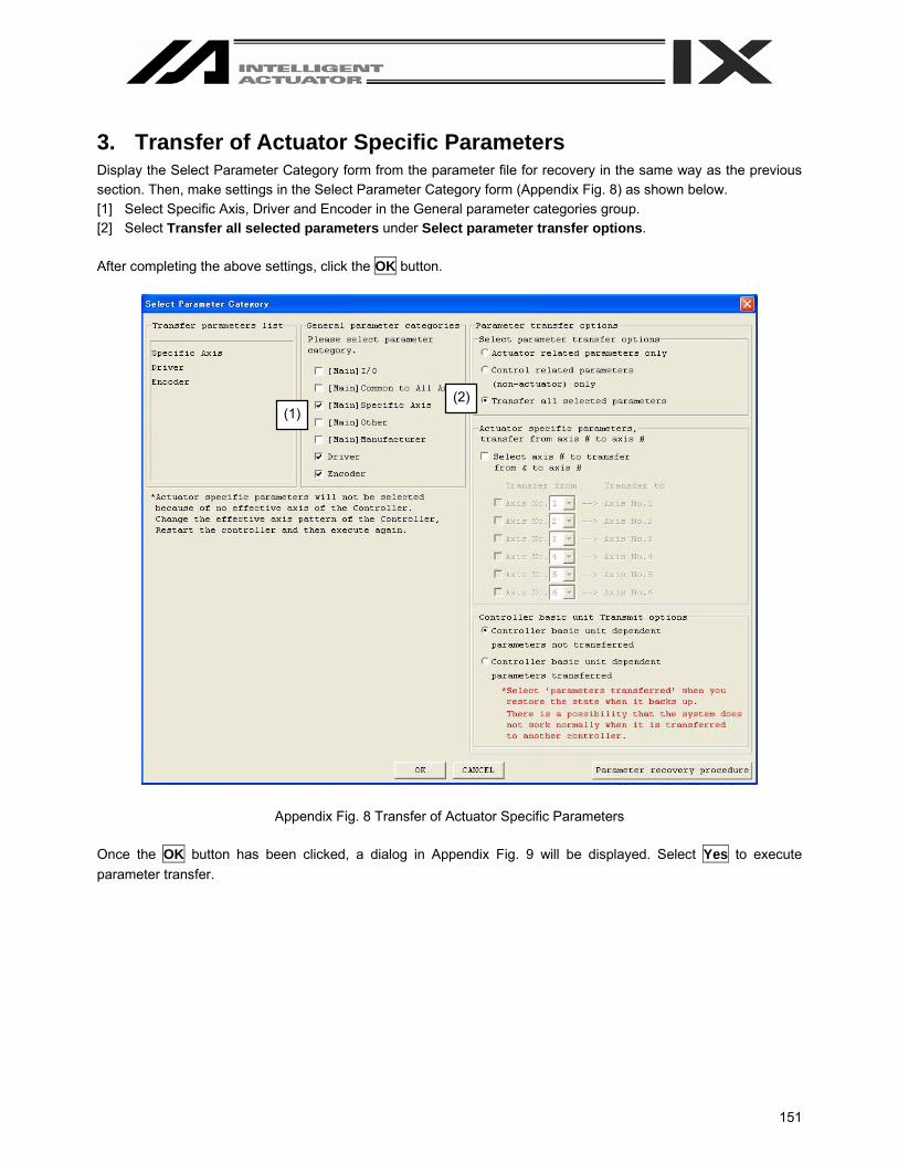
151
3. Transfer of Actuator Specific Parameters Display the Select Parameter Category form from the parameter file for recovery in the same way as the previous section. Then, make settings in the Select Parameter Category form (Appendix Fig. 8) as shown below. [1] Select Specific Axis, Driver and Encoder in the General parameter categories group. [2] Select Transfer all selected parameters under Select parameter transfer options. After completing the above settings, click the OK button.
Appendix Fig. 8 Transfer of Actuator Specific Parameters Once the OK button has been clicked, a dialog in Appendix Fig. 9 will be displayed. Select Yes to execute parameter transfer.
(1) (2)

152
Appendix Fig. 9 Warning Dialog before Transfer of Actuator Specific Parameters After performing this procedure, always write the parameters to the flash ROM and reset software. This completes transfer of all parameter data. Confirm that parameters are recovered to the conditions at backup time.
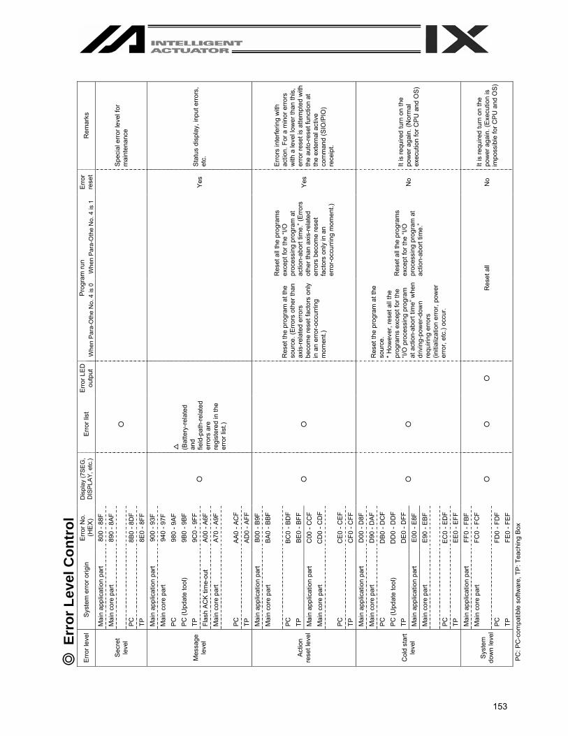
153
R
emar
ks
Spec
ial e
rror l
evel
for
mai
nten
ance
Stat
us d
ispl
ay, i
nput
erro
rs,
etc.
Erro
rs in
terfe
ring
with
ac
tion.
For
a m
inor
err
ors
with
a le
vel l
ower
than
this
, er
ror r
eset
is a
ttem
pted
with
th
e au
to-r
eset
func
tion
at
the
exte
rnal
act
ive
com
man
d (S
IO/P
IO)
rece
ipt.
It is
requ
ired
turn
on
the
pow
er a
gain
. (N
orm
al
exec
utio
n fo
r CPU
and
OS)
It is
requ
ired
turn
on
the
pow
er a
gain
. (Ex
ecut
ion
is
impo
ssib
le fo
r CP
U a
nd O
S)
Erro
r re
set
Yes
Yes
No
No
Whe
n Pa
ra-O
the
No.
4 is
1
Res
et a
ll th
e pr
ogra
ms
exce
pt fo
r the
“I/O
pr
oces
sing
pro
gram
at
actio
n-ab
ort t
ime.
” (Er
rors
ot
her t
han
axis
-rela
ted
erro
rs b
ecom
e re
set
fact
ors
only
in a
n er
ror-
occu
rring
mom
ent.)
Res
et a
ll th
e pr
ogra
ms
exce
pt fo
r the
“I/O
pr
oces
sing
pro
gram
at
actio
n-ab
ort t
ime.
”
Prog
ram
run
Whe
n P
ara-
Oth
e N
o. 4
is 0
Res
et th
e pr
ogra
m a
t the
so
urce
. (Er
rors
oth
er th
an
axis
-rela
ted
erro
rs
beco
me
rese
t fac
tors
onl
y in
an
erro
r-occ
urrin
g m
omen
t.)
Res
et th
e pr
ogra
m a
t the
so
urce
. *
How
ever
, res
et a
ll th
e pr
ogra
ms
exce
pt fo
r the
“I/
O p
roce
ssin
g pr
ogra
m
at a
ctio
n-ab
ort t
ime”
whe
n dr
ivin
g-po
wer
-dow
n re
quiri
ng e
rrors
(in
itial
izat
ion
erro
r, po
wer
er
ror,
etc.
) occ
ur.
Res
et a
ll
Erro
r LE
D
outp
ut
○
Erro
r lis
t
○
△
(Bat
tery
-rela
ted
and
field
-pat
h-re
late
d er
rors
are
re
gist
ered
in th
e er
ror l
ist.)
○
○
○
Dis
play
(7S
EG,
DIS
PLAY
, etc
.)
○
○
○
○
Erro
r No.
(H
EX
) 80
0 - 8
8F
890
- 8AF
8B0
- 8D
F 8E
0 - 8
FF
900
- 93F
94
0 - 9
7F
980
- 9AF
9B
0 - 9
BF
9C0
- 9FF
A0
0 - A
6F
A70
- A9F
AA0
- AC
F AD
0 - A
FF
B00
- B9F
BA
0 - B
BF
BC
0 - B
DF
BE0
- BF
F C
00 -
CC
F C
D0
- CD
F
CE
0 - C
EF
CF0
- C
FF
D00
- D
8F
D90
- D
AF
DB
0 - D
CF
DD
0 - D
DF
DE
0 - D
FF
E00
- E8F
E9
0 - E
BF
EC
0 - E
DF
EE0
- EF
F FF
0 - F
BF
FC0
- FC
F
FD0
- FD
F FE
0 - F
EF
Syst
em e
rror o
rigin
Mai
n ap
plic
atio
n pa
rt M
ain
core
par
t PC
TP
M
ain
appl
icat
ion
part
Mai
n co
re p
art
PC
PC (U
pdat
e to
ol)
TP
Flas
h A
CK
time-
out
Mai
n co
re p
art
PC
TP
Mai
n ap
plic
atio
n pa
rt M
ain
core
par
t PC
TP
M
ain
appl
icat
ion
part
Mai
n co
re p
art
PC
TP
Mai
n ap
plic
atio
n pa
rt M
ain
core
par
t PC
PC
(Upd
ate
tool
) TP
M
ain
appl
icat
ion
part
Mai
n co
re p
art
PC
TP
Mai
n ap
plic
atio
n pa
rt M
ain
core
par
t PC
TP
◎ E
rror
Lev
el C
ontr
ol
Erro
r lev
el
Secr
et
leve
l
Mes
sage
le
vel
Actio
n re
set l
evel
Col
d st
art
leve
l
Syst
em
dow
n le
vel
PC: P
C-c
ompa
tible
sof
twar
e, T
P: T
each
ing
Box

154
Spe
cial
not
e
Pro
gram
cop
y/m
ove/
clea
r was
per
form
ed w
hile
the
onlin
e pr
ogra
m e
dit w
indo
w w
as o
pen.
C
lose
the
onlin
e pr
ogra
m e
dit w
indo
w fi
rst.
Pro
gram
file
tran
sfer
was
per
form
ed to
/from
the
prog
ram
bei
ng e
dite
d on
line.
C
lose
the
onlin
e ed
it w
indo
w fo
r the
targ
et p
rogr
am fi
rst.
Pos
ition
dat
a co
py/m
ove/
clea
r was
per
form
ed w
hile
the
onlin
e po
sitio
n da
ta e
dit w
indo
w w
as o
pen.
C
lose
the
onlin
e po
sitio
n da
ta e
dit w
indo
w fi
rst.
Pos
ition
dat
a fil
e tra
nsfe
r was
per
form
ed w
hile
the
onlin
e po
sitio
n da
ta e
dit w
indo
w w
as o
pen.
C
lose
the
onlin
e po
sitio
n da
ta e
dit w
indo
w fi
rst.
Par
amet
er fi
le tr
ansf
er w
as p
erfo
rmed
whi
le th
e on
line
para
met
er e
dit w
indo
w w
as o
pen.
C
lose
the
onlin
e pa
ram
eter
edi
t win
dow
firs
t. S
ymbo
l dat
a cl
ear w
as p
erfo
rmed
whi
le th
e on
line
sym
bol d
ata
edit
win
dow
was
ope
n.
Clo
se th
e on
line
sym
bol d
ata
edit
win
dow
firs
t. S
ymbo
l dat
a fil
e tra
nsfe
r was
per
form
ed w
hile
the
onlin
e sy
mbo
l dat
a ed
it w
indo
w w
as o
pen.
C
lose
the
onlin
e sy
mbo
l dat
a ed
it w
indo
w fi
rst.
Mem
ory
initi
aliz
atio
n w
as p
erfo
rmed
whi
le th
e pr
ogra
m/s
ymbo
l/pos
ition
dat
a on
line
edit
win
dow
was
op
en. C
lose
the
appl
icab
le o
nlin
e ed
it w
indo
w fi
rst.
Jogg
ing
was
per
form
ed fo
r an
axis
who
se s
ervo
was
OFF
. Tur
n O
N th
e se
rvo
first
.
The
spec
ified
acc
eler
atio
n du
ring
jog,
mov
e or
con
tinuo
us m
ove
exce
eds
the
allo
wab
le ra
nge
or is
in
valid
. Che
ck th
e sp
ecifi
ed a
ccel
erat
ion.
The
spec
ified
dec
eler
atio
n du
ring
jog,
mov
e or
con
tinuo
us m
ove
exce
eds
the
allo
wab
le ra
nge
or is
in
valid
. Che
ck th
e sp
ecifi
ed d
ecel
erat
ion.
Writ
e, c
opy,
mov
e, c
lear
or o
ther
edi
t ope
ratio
n w
as p
erfo
rmed
for t
he p
rogr
am c
urre
ntly
runn
ing.
E
nd th
e pr
ogra
m y
ou w
ish
to e
dit,
and
then
try
agai
n.
Ther
e ar
e no
t eno
ugh
empt
y st
eps
in th
e co
ntro
ller.
Dat
a ed
it op
erat
ion
(writ
e, c
opy,
mov
e, c
lear
, etc
.) w
as p
erfo
rmed
in n
on-m
anua
l mod
e.
The
num
ber o
f dat
a se
ts in
the
file
(num
ber o
f ste
ps, n
umbe
r of p
ositi
ons,
etc
.) ex
ceed
s th
e al
low
able
va
lue.
Th
e nu
mbe
r of d
ata
sets
writ
ten
to th
e fil
e (n
umbe
r of s
teps
, num
ber o
f pos
ition
s, e
tc.)
exce
eds
the
allo
wab
le v
alue
. Th
e sp
ecifi
ed b
aud
rate
is in
valid
(at c
onne
ctio
n ch
eck,
whe
n ch
angi
ng th
e ba
ud ra
te, e
tc.).
Dat
a re
ad fr
om a
file
can
not b
e tra
nsfe
rred
to th
e co
ntro
ller d
urin
g da
ta tr
ansm
issi
on (i
.e. w
hile
dat
a is
be
ing
read
or w
ritte
n).
Err
or n
ame
Can
not C
opy,
Mov
e, C
lear
Pro
gram
bei
ng e
dite
d on
-line
.
Can
not t
rans
mit
the
prog
ram
file
bei
ng e
dite
d on
-line
.
Can
not C
opy,
Mov
e, C
lear
Pos
ition
dat
a be
ing
edite
d on
-line
.
Can
not t
rans
mit
the
Pos
ition
dat
a be
ing
edite
d on
-line
.
Can
not t
rans
mit
the
Par
amet
er fi
le b
eing
edi
ted
on-li
ne.
Can
not C
lear
Sym
bol d
ata
bein
g ed
ited
on-li
ne.
Can
not t
rans
mit
Sym
bol d
ata
file
bein
g ed
ited
on-li
ne.
Can
not i
nitia
lize
mem
ory
bein
g ed
ited
on-li
ne.
Can
not J
og w
hen
Ser
vo O
FF.
Acc
eler
atio
n sp
ecifi
catio
n er
ror f
or jo
g, m
ove
or
cont
inuo
us m
ove.
Dec
eler
atio
n sp
ecifi
catio
n er
ror f
or jo
g, m
ove
or
cont
inuo
us m
ove.
Can
not e
dit w
hile
runn
ing
prog
ram
. (P
C)
Lack
ing
Em
pty
Ste
p (P
C)
Dat
a ed
iting
pro
hibi
ted
in n
on-m
anua
l mod
e
Can
not r
ead
so m
any
data
from
the
file.
Can
not w
rite
so m
any
data
to th
e fil
e.
Bau
d ra
te s
peci
ficat
ion
erro
r.
File
dat
a tra
nsfe
r pro
hibi
ted
durin
g da
ta tr
ansm
issi
on.
X-SE
L PC
Sof
twar
e Er
ror T
able
(E
rror
s sp
ecifi
c to
the
PC
Sof
twar
e ar
e lis
ted
belo
w. S
ee th
e X
-SE
L C
ontro
ller O
pera
tion
Man
ual f
or c
ontro
ller e
rror
s.)
Err
or N
o.
980
981
982
983
984
985
986
987
988
989
98A
98B
98C
98D
98E
98F
990
991

155
Sp
ecia
l not
e C
oord
inat
e sy
stem
def
initi
on d
ata
cann
ot b
e cl
eare
d w
hile
the
onlin
e ed
it w
indo
w fo
r coo
rdin
ate
syst
em d
efin
ition
dat
a is
ope
n. C
lose
the
onlin
e ed
it w
indo
w fi
rst.
Arm
can
not b
e ch
ange
d w
hile
the
serv
o is
OFF
.
The
coor
dina
te s
yste
m d
efin
ition
dat
a fil
e w
as tr
ansf
erre
d w
hile
the
onlin
e ed
it w
indo
w fo
r coo
rdin
ate
syst
em d
efin
ition
dat
a is
ope
n.
Clo
se th
e on
line
edit
win
dow
firs
t.
The
spec
ified
axi
s pa
ttern
s fo
r Coo
rdin
ate
1 an
d C
oord
inat
e 2
of th
e si
mpl
e in
terfe
renc
e ch
eck
zone
de
finiti
on d
ata
do n
ot m
atch
. C
oord
inat
e va
lues
are
not
ent
ered
in th
e si
mpl
e in
terfe
renc
e ch
eck
zone
def
initi
on d
ata.
Cer
tain
ope
ratio
ns, s
uch
as re
ad, c
opy
and
mov
e, c
anno
t be
perfo
rmed
for r
ead-
prot
ecte
d da
ta.
Cer
tain
ope
ratio
ns, s
uch
as re
ad, c
opy,
mov
e an
d cl
ear,
cann
ot b
e pe
rform
ed fo
r writ
e-pr
otec
ted
data
.
An
inva
lid v
alue
is s
et in
pro
tect
ion
setti
ng p
aram
eter
s (O
ther
Par
amet
er N
os. 3
6 - 3
9).
The
spec
ifica
tion
of th
e nu
mbe
r of p
oint
dat
a is
abn
orm
al.
The
spec
ifica
tion
of th
e co
mm
unic
atio
n so
cket
num
ber i
s ab
norm
al.
Uns
uppo
rted
func
tion.
A v
alue
out
side
the
allo
wab
le ra
nge
or in
valid
cha
ract
er h
as b
een
inpu
t.
The
ente
red
pass
wor
d is
inva
lid. E
nter
the
corr
ect p
assw
ord.
Dat
a ed
it w
as p
erfo
rmed
in o
pera
ting
mod
e. C
heck
the
type
of m
anua
l ope
ratio
n (O
ther
Par
amet
er N
o.
21 a
nd th
e ty
pe o
f man
ual P
C S
oftw
are
oper
atio
n cu
rrent
ly s
elec
ted)
.
Dat
a w
rite
was
per
form
ed w
hile
the
flash
RO
M w
as w
ritte
n.
Dat
a ed
it ca
nnot
be
perfo
rmed
whi
le th
e fla
sh R
OM
is w
ritte
n.
The
data
read
from
a fi
le is
abn
orm
al.
Dat
a tra
nsm
issi
on c
anno
t be
perfo
rmed
whi
le th
e co
mm
unic
atio
n w
ith th
e co
ntro
ller i
s cu
t off.
Tr
y ag
ain
afte
r sta
rting
the
appl
icat
ion
in o
nlin
e m
ode.
Teac
hing
ope
ratio
n (c
urre
nt p
ositi
on c
aptu
re) w
as p
erfo
rmed
for a
n ax
is w
hose
hom
ing
was
not
yet
co
mpl
ete.
Com
plet
e ho
min
g fir
st.
Mem
ory
initi
aliz
atio
n w
as p
erfo
rmed
in o
pera
ting
mod
e. C
heck
the
type
of m
anua
l ope
ratio
n (O
ther
P
aram
eter
No.
21
and
the
type
of m
anua
l PC
Sof
twar
e op
erat
ion
curre
ntly
sel
ecte
d).
Err
or n
ame
Cle
ar o
f coo
rdin
ate
syst
em d
efin
ition
dat
a pr
ohib
ited
whi
le b
eing
edi
ted
on-li
ne
Arm
cha
nge
proh
ibite
d w
hen
serv
o O
FF
Tran
sfer
of a
coo
rdin
ate
syst
em d
ata
file
proh
ibite
d w
hile
bei
ng e
dite
d on
-line
E
ffect
ive
axis
pat
tern
mis
mat
ch e
rror
in ‘C
rd1’
and
‘C
rd2’
O
utpu
t por
t/fla
g er
ror t
ype
spec
ifica
tion
proh
ibite
d w
hen
the
effe
ctiv
e ax
is p
atte
rn is
0 fo
r ‘C
rd1’
and
‘Crd
2’
Can
not
sel
ect s
o m
any
axes
for m
onito
ring
Rea
d-pr
otec
ted
data
read
erro
r
Writ
e-pr
otec
ted
data
writ
e er
ror
Pro
tect
ion
setti
ng p
aram
eter
err
or
Pos
ition
No.
spe
cific
atio
n er
ror
Por
t No.
spe
cific
atio
n er
ror
Func
tion
unsu
ppor
t rej
ectio
n er
ror (
PC
)
Inpu
t dat
a er
ror
Pas
swor
d E
rror
.
Faile
d in
writ
ing
file.
Dat
a ed
it pr
ohib
ited
in o
pera
ting
mod
e
Dat
a w
rite
proh
ibite
d du
ring
flash
RO
M w
rite
File
dat
a er
ror
Jog/
mov
e/co
ntin
uous
mov
e sp
eed
too
low
Jog/
mov
e/co
ntin
uous
mov
e sp
eed
too
high
Dat
a tra
nsm
issi
on n
ot p
ossi
ble
offli
ne
Teac
hing
pro
hibi
ted
befo
re c
ompl
etio
n of
hom
ing
Mem
ory
initi
aliz
atio
n pr
ohib
ited
in o
pera
ting
mod
e
Err
or N
o.
992
993
994
995
996
997
998
999
99A
99B
99C
99E
AA
0
AA
1
AA
2
AA
3
AA
4
AA
5
AA
6
AA
7
AA
8
AA
9
AA
A
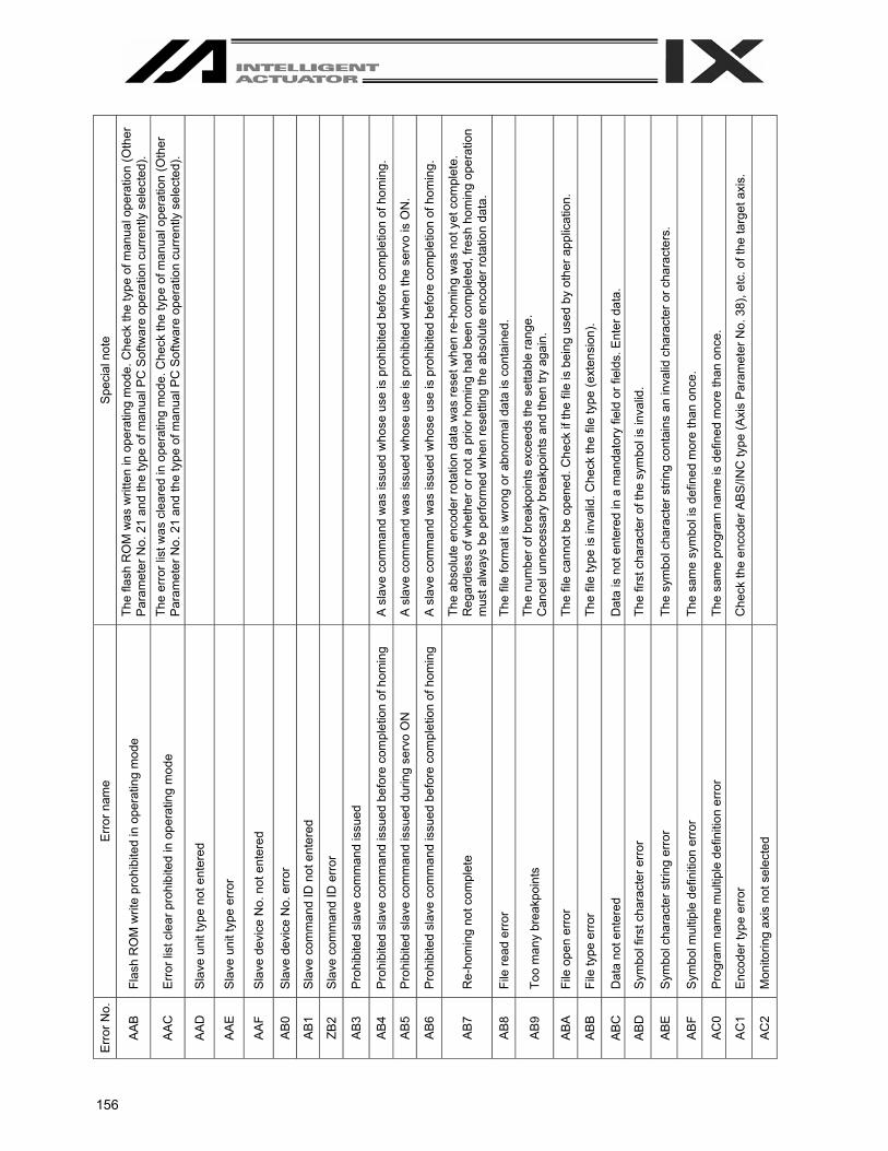
156
Spe
cial
not
e
The
flash
RO
M w
as w
ritte
n in
ope
ratin
g m
ode.
Che
ck th
e ty
pe o
f man
ual o
pera
tion
(Oth
er
Par
amet
er N
o. 2
1 an
d th
e ty
pe o
f man
ual P
C S
oftw
are
oper
atio
n cu
rrent
ly s
elec
ted)
. Th
e er
ror l
ist w
as c
lear
ed in
ope
ratin
g m
ode.
Che
ck th
e ty
pe o
f man
ual o
pera
tion
(Oth
er
Par
amet
er N
o. 2
1 an
d th
e ty
pe o
f man
ual P
C S
oftw
are
oper
atio
n cu
rrent
ly s
elec
ted)
.
A s
lave
com
man
d w
as is
sued
who
se u
se is
pro
hibi
ted
befo
re c
ompl
etio
n of
hom
ing.
A s
lave
com
man
d w
as is
sued
who
se u
se is
pro
hibi
ted
whe
n th
e se
rvo
is O
N.
A s
lave
com
man
d w
as is
sued
who
se u
se is
pro
hibi
ted
befo
re c
ompl
etio
n of
hom
ing.
The
abso
lute
enc
oder
rota
tion
data
was
rese
t whe
n re
-hom
ing
was
not
yet
com
plet
e.
Reg
ardl
ess
of w
heth
er o
r not
a p
rior h
omin
g ha
d be
en c
ompl
eted
, fre
sh h
omin
g op
erat
ion
mus
t alw
ays
be p
erfo
rmed
whe
n re
setti
ng th
e ab
solu
te e
ncod
er ro
tatio
n da
ta.
The
file
form
at is
wro
ng o
r abn
orm
al d
ata
is c
onta
ined
.
The
num
ber o
f bre
akpo
ints
exc
eeds
the
setta
ble
rang
e.
Can
cel u
nnec
essa
ry b
reak
poin
ts a
nd th
en tr
y ag
ain.
The
file
cann
ot b
e op
ened
. Che
ck if
the
file
is b
eing
use
d by
oth
er a
pplic
atio
n.
The
file
type
is in
valid
. Che
ck th
e fil
e ty
pe (e
xten
sion
).
Dat
a is
not
ent
ered
in a
man
dato
ry fi
eld
or fi
elds
. Ent
er d
ata.
The
first
cha
ract
er o
f the
sym
bol i
s in
valid
.
The
sym
bol c
hara
cter
stri
ng c
onta
ins
an in
valid
cha
ract
er o
r cha
ract
ers.
The
sam
e sy
mbo
l is
defin
ed m
ore
than
onc
e.
The
sam
e pr
ogra
m n
ame
is d
efin
ed m
ore
than
onc
e.
Che
ck th
e en
code
r AB
S/IN
C ty
pe (A
xis
Par
amet
er N
o. 3
8), e
tc. o
f the
targ
et a
xis.
Err
or n
ame
Flas
h R
OM
writ
e pr
ohib
ited
in o
pera
ting
mod
e
Err
or li
st c
lear
pro
hibi
ted
in o
pera
ting
mod
e
Sla
ve u
nit t
ype
not e
nter
ed
Sla
ve u
nit t
ype
erro
r
Sla
ve d
evic
e N
o. n
ot e
nter
ed
Sla
ve d
evic
e N
o. e
rror
Sla
ve c
omm
and
ID n
ot e
nter
ed
Sla
ve c
omm
and
ID e
rror
Pro
hibi
ted
slav
e co
mm
and
issu
ed
Pro
hibi
ted
slav
e co
mm
and
issu
ed b
efor
e co
mpl
etio
n of
hom
ing
Pro
hibi
ted
slav
e co
mm
and
issu
ed d
urin
g se
rvo
ON
Pro
hibi
ted
slav
e co
mm
and
issu
ed b
efor
e co
mpl
etio
n of
hom
ing
Re-
hom
ing
not c
ompl
ete
File
read
err
or
Too
man
y br
eakp
oint
s
File
ope
n er
ror
File
type
err
or
Dat
a no
t ent
ered
Sym
bol f
irst c
hara
cter
erro
r
Sym
bol c
hara
cter
stri
ng e
rror
Sym
bol m
ultip
le d
efin
ition
erro
r
Pro
gram
nam
e m
ultip
le d
efin
ition
err
or
Enc
oder
type
err
or
Mon
itorin
g ax
is n
ot s
elec
ted
Err
or N
o.
AA
B
AA
C
AA
D
AA
E
AA
F
AB
0
AB
1
ZB2
AB
3
AB
4
AB
5
AB
6
AB
7
AB
8
AB
9
AB
A
AB
B
AB
C
AB
D
AB
E
AB
F
AC
0
AC
1
AC
2
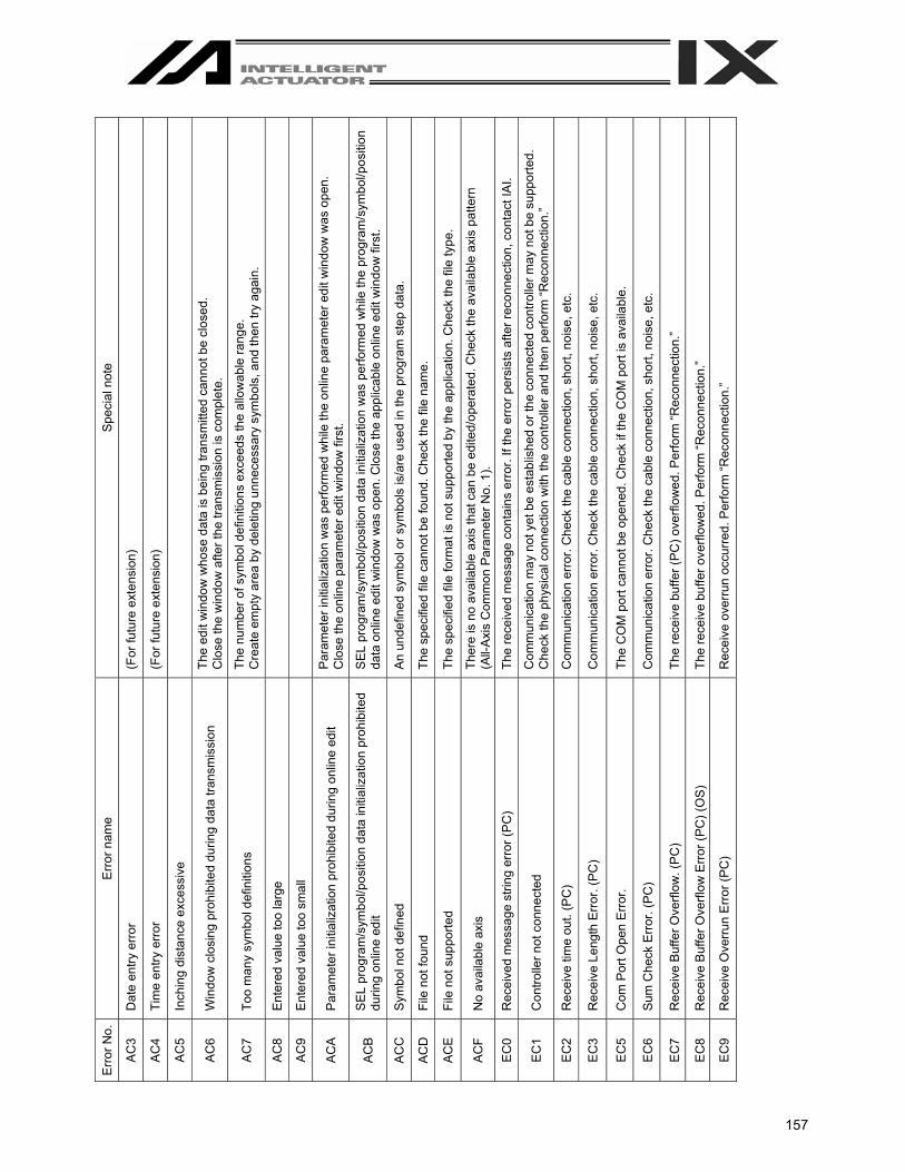
157
Sp
ecia
l not
e
(For
futu
re e
xten
sion
)
(For
futu
re e
xten
sion
)
The
edit
win
dow
who
se d
ata
is b
eing
tran
smitt
ed c
anno
t be
clos
ed.
C
lose
the
win
dow
afte
r the
tran
smis
sion
is c
ompl
ete.
The
num
ber o
f sym
bol d
efin
ition
s ex
ceed
s th
e al
low
able
rang
e.
Cre
ate
empt
y ar
ea b
y de
letin
g un
nece
ssar
y sy
mbo
ls, a
nd th
en tr
y ag
ain.
Par
amet
er in
itial
izat
ion
was
per
form
ed w
hile
the
onlin
e pa
ram
eter
edi
t win
dow
was
ope
n.
Clo
se th
e on
line
para
met
er e
dit w
indo
w fi
rst.
SE
L pr
ogra
m/s
ymbo
l/pos
ition
dat
a in
itial
izat
ion
was
per
form
ed w
hile
the
prog
ram
/sym
bol/p
ositi
on
data
onl
ine
edit
win
dow
was
ope
n. C
lose
the
appl
icab
le o
nlin
e ed
it w
indo
w fi
rst.
An
unde
fined
sym
bol o
r sym
bols
is/a
re u
sed
in th
e pr
ogra
m s
tep
data
.
The
spec
ified
file
can
not b
e fo
und.
Che
ck th
e fil
e na
me.
The
spec
ified
file
form
at is
not
sup
porte
d by
the
appl
icat
ion.
Che
ck th
e fil
e ty
pe.
Ther
e is
no
avai
labl
e ax
is th
at c
an b
e ed
ited/
oper
ated
. Che
ck th
e av
aila
ble
axis
pat
tern
(A
ll-Ax
is C
omm
on P
aram
eter
No.
1).
The
rece
ived
mes
sage
con
tain
s er
ror.
If th
e er
ror p
ersi
sts
afte
r rec
onne
ctio
n, c
onta
ct IA
I.
Com
mun
icat
ion
may
not
yet
be
esta
blis
hed
or th
e co
nnec
ted
cont
rolle
r may
not
be
supp
orte
d.
Che
ck th
e ph
ysic
al c
onne
ctio
n w
ith th
e co
ntro
ller a
nd th
en p
erfo
rm “R
econ
nect
ion.
”
Com
mun
icat
ion
erro
r. C
heck
the
cabl
e co
nnec
tion,
sho
rt, n
oise
, etc
.
Com
mun
icat
ion
erro
r. C
heck
the
cabl
e co
nnec
tion,
sho
rt, n
oise
, etc
.
The
CO
M p
ort c
anno
t be
open
ed. C
heck
if th
e C
OM
por
t is
avai
labl
e.
Com
mun
icat
ion
erro
r. C
heck
the
cabl
e co
nnec
tion,
sho
rt, n
oise
, etc
.
The
rece
ive
buffe
r (P
C) o
verfl
owed
. Per
form
“Rec
onne
ctio
n.”
The
rece
ive
buffe
r ove
rflow
ed. P
erfo
rm “R
econ
nect
ion.
”
Rec
eive
ove
rrun
occ
urre
d. P
erfo
rm “R
econ
nect
ion.
”
Err
or n
ame
Dat
e en
try e
rror
Tim
e en
try e
rror
Inch
ing
dist
ance
exc
essi
ve
Win
dow
clo
sing
pro
hibi
ted
durin
g da
ta tr
ansm
issi
on
Too
man
y sy
mbo
l def
initi
ons
Ent
ered
val
ue to
o la
rge
Ent
ered
val
ue to
o sm
all
Par
amet
er in
itial
izat
ion
proh
ibite
d du
ring
onlin
e ed
it
SE
L pr
ogra
m/s
ymbo
l/pos
ition
dat
a in
itial
izat
ion
proh
ibite
d du
ring
onlin
e ed
it
Sym
bol n
ot d
efin
ed
File
not
foun
d
File
not
sup
porte
d
No
avai
labl
e ax
is
Rec
eive
d m
essa
ge s
tring
err
or (P
C)
Con
trolle
r not
con
nect
ed
Rec
eive
tim
e ou
t. (P
C)
Rec
eive
Len
gth
Err
or. (
PC
)
Com
Por
t Ope
n E
rror
.
Sum
Che
ck E
rror
. (P
C)
Rec
eive
Buf
fer O
verfl
ow. (
PC
)
Rec
eive
Buf
fer O
verfl
ow E
rror
(PC
) (O
S)
Rec
eive
Ove
rrun
Err
or (P
C)
Err
or N
o.
AC
3
AC
4
AC
5
AC
6
AC
7
AC
8
AC
9
AC
A
AC
B
AC
C
AC
D
AC
E
AC
F
EC
0
EC
1
EC
2
EC
3
EC
5
EC
6
EC
7
EC
8
EC
9

158
Spec
ial n
ote
Fram
ing
erro
r occ
urre
d. P
erfo
rm “r
econ
nect
ion.
”
Com
mun
icat
ion
erro
r occ
urre
d. P
erfo
rm “r
econ
nect
ion.
”
The
conn
ecte
d co
ntro
ller i
s no
t sup
porte
d.
Com
mun
icat
ion
erro
r. C
heck
the
HU
B, c
able
con
nect
ion,
sho
rt, n
oise
, etc
.
Com
mun
icat
ion
erro
r. C
heck
the
HU
B, c
able
con
nect
ion,
sho
rt, n
oise
, etc
.
Com
mun
icat
ion
erro
r. Th
e ca
ble
may
be
rem
oved
or d
isco
nnec
ted.
The
spec
ified
por
t num
ber m
ay b
e be
ing
used
by
anot
her c
onne
ctio
n. C
hang
e th
e po
rt nu
mbe
r.
This
err
or o
ccur
s w
hen
64 o
r mor
e co
ntro
llers
are
con
nect
ed.
Err
or n
ame
Fram
ing
Err
or (P
C)
Com
mun
icat
ion
Err
or (P
C) (
OS
)
Uns
uppo
rted
cont
rolle
r con
nect
ion
erro
r
Eth
erne
t Rec
eive
Tim
eout
Err
or (P
C)
Dis
conn
ectio
n E
rror
(PC
)
Soc
ket E
rror
(PC
)
Ser
vice
Por
t No.
Bei
ng U
sed
(PC
)
Can
not c
onne
ct s
o m
any
sock
ets
(PC
)
Err
or N
o.
EC
A
EC
B
EC
C
EC
D
EC
E
EC
F
ED
0
ED
1

MEMO
159

MEMO
160


Catalog No.: MJ0154-1B (September 2006)
IAI America Inc. Head Office: 2690W 237th Street Torrance, CA 90505
TEL (310) 891-6015 FAX (310) 891-0815 Chicago Office: 1261 Hamilton Parkway Itasca, IL 60143
TEL (630) 467-9900 FAX (630) 467-9912
Home page: www.intelligentactuator.com
IAI Industrieroboter GmbH Ober der Röth 4, D-65824 Schwalbach am Taunus, Germany
TEL 06196-88950 FAX 06196-889524
The prices, specifications, dimensions and other information provided in this manual are subject to change without notice for purposes of product improvement. Copyright © 2006 Sept. IAI Corporation. All rights reserved.