payload 4(part1)
TRANSCRIPT
8/7/2019 Payload 4(Part1)
http://slidepdf.com/reader/full/payload-4part1 1/100
Chapter 5: SONET/SDH
Reference textbook:³Understanding SONET/SDH and ATM:Communications Networks for The Next
Millennium´ By S1. V. Kartalopoulos

8/7/2019 Payload 4(Part1)
http://slidepdf.com/reader/full/payload-4part1 2/100
Introduction
³Humans are social animals!´Socializing exchanging ideas and information buildnetworks to facilitate information exchange andcommunication
Different ways of communication technologieso Telegrapho Telephonyo Digital electronic technology of various data types
Telemetry data
User dataVideo dataVoice data

8/7/2019 Payload 4(Part1)
http://slidepdf.com/reader/full/payload-4part1 3/100
F ig. 5.1 Characteristics per service

8/7/2019 Payload 4(Part1)
http://slidepdf.com/reader/full/payload-4part1 4/100
5.1 Legacy Communications Systems:
Concepts
Basic Technology and Services

8/7/2019 Payload 4(Part1)
http://slidepdf.com/reader/full/payload-4part1 5/100
P ulse-Coded Modulation ( P CM )
Voice : the primary services in the communication industryo Voice : analog signal.o Words : acoustic waves generated by vibrating vocal cords and the
mouth cavity modulates them into recognizable and distinguishablecompounded sounds
o Microphone: a transducer converts acoustic waves into (analog)electrical signalso Speaker: a transducer converts (analog) electrical signals into
acoustic waves and reproduces voice soundsP OTS ( P lain Old Telephone Service )
o Ringingo call initiationo number dialingo Transmits analog signals over the telephone network

8/7/2019 Payload 4(Part1)
http://slidepdf.com/reader/full/payload-4part1 6/100
P ulse-Coded Modulation ( P CM )
P CM form a binary (or digital) bit stream at 64000 bits/secondAlso know as Digital S ignal level 0 ( DS0 )(en)Coder : converts analog signal into digital bit steamsDecoder : converts digital bit streams into analog signal (voices)CODEC ( coder/decoder ) : periodically samples the analog signal, and basedon a conversion scheme, it translates each sampled value into a binaryrepresentationTwo major schemes for P CM : -law in United States, -low in EuropeAcoustical signal of speaking voice : usually under 3.4 kilocycles per second,or kilohertz ( 3.4 kHz )A low-pass filter removes all components of frequency higher than 3.4 kHzBy sampling theorem, to truly represent a signal, we must sample at least
twice as its maximum frequency contentSo P CM CODEC samples at analog voices 8000 times per second, or every125 ms, and it converts each sample into 8 bits P CMThe total bit rate is 8000 × 8 = 64000 bits / second, or 64 kilobits per second (64 Kbps ), this is the rate termed DS0.

8/7/2019 Payload 4(Part1)
http://slidepdf.com/reader/full/payload-4part1 7/100
F ig. 5.2 Analog to P CM

8/7/2019 Payload 4(Part1)
http://slidepdf.com/reader/full/payload-4part1 8/100
F ig. 5.3 DS0 rate
8/7/2019 Payload 4(Part1)
http://slidepdf.com/reader/full/payload-4part1 9/100
P ulse-Coded Modulation ( P CM )
Differential P CM ( D P CM ) , adaptive D P CM ( AD P CM ),and sigma-delta P CM ( P CM ) : by more sophisticateddigital signal processing algorithms to compress the 64Kbps to 32 Kbps, or 16 Kbps, or even lower than that.
Local loop : a pair of twisted copper wires between user¶sequipment ( a P OTS telephone ) and the serviceprovider¶s equipment, where the CODEC is located. Thesignal transmitted on a local loop cable is an analogelectrical signal.

8/7/2019 Payload 4(Part1)
http://slidepdf.com/reader/full/payload-4part1 10/100
Time-Division Multiplexing ( TDM )
P OTS telephone converts voice signals into an electricalsignalThe electrical signal is sent over a pair of copper wires toa communications systems where the CODEC function is
performedThe backbone network only transmits digital signals andno analog signals : all-digital communications networkOn an all-digital communications network, in addition todigitized voice signals, other digital data can also betransmitted ( raw digital data, encoded video, encodedsound, etc. )

8/7/2019 Payload 4(Part1)
http://slidepdf.com/reader/full/payload-4part1 11/100
Time-Division Multiplexing ( TDM )
Some digital services on DS0o Digital Data Service ( DDS )
56 Kbps for data, 8 Kbps for ³in-band´ signalingOnly for the backbone network, not for the end users
o Basic Rate Integrated Services Digital Network ( BR ISDN or BR I )Uses two 64 Kbps channels ( channels B ) and a 16 Kbps subratechannel ( channel D )Support a combination of voice and/or data services over a single pair of wireModes available for end users :
2 B channels for voice and a D channel for data1 B channel for voice and a B+D channels for data
2 B channels for data and a D channel for signaling All channels for dataCan only be used if both end users has ISDN and the network supportsISDN

8/7/2019 Payload 4(Part1)
http://slidepdf.com/reader/full/payload-4part1 12/100
Abbreviations :CCC, clear channel capability;B = 64 Kbps voice or data channel;DDS, digital data services;D = 16 Kbps signaling or data channel
B8ZSB channel ( 2B + D )
64 CCCB-ISDN 64 Kbps
64 CCCB8ZS
DDS 56 Kbps + 8 Kbps signalling
F rame, bit robbedVoice : 64 Kbps
F ormat, overheadline code
Source
Table 5.1 DS0 Rates and Line Codes

8/7/2019 Payload 4(Part1)
http://slidepdf.com/reader/full/payload-4part1 13/100
Time-Division Multiplexing ( TDM )
User-to-network interface ( UN I ) : the interface where theuser signal, a 64 Kbps data stream ( organized in 8-bitbytes ), first meets the networkAt UNI, users¶ signals are synchronized with a 8 kHz
system clock, or a multiple of it.Then based on a round-robin principle, the signals aresequentially polled one byte at a time and place one after the other in a fixed order, this is called byte-interleaving.Time slot : the location of each byte source in this ordereddigital signal.The whole process is called Time-Division Multiplexing (TDM ).

8/7/2019 Payload 4(Part1)
http://slidepdf.com/reader/full/payload-4part1 14/100
DS1 Rate
Multiplex 24 DS0 usersEach user contributes one byte in a DS1 frameAn additional bit, the F -bit, is used as the beginning of a DS1frameTotal 24 × 8 + 1 = 193 bits in 125 s.The bit rate is 193 bits / 125 ms = 1.544 Mbps, knows as thedigital signal level 1 ( DS1 ) rate.M1 multiplexer ( M1 mux ) : function that TDM 24 DS0 into aDS1.The F -bit of each frame forms an F subrate channel in DS1
superframeo 12 or 24 frames in each super frameo P rovide a data link over which the network data are sento P rovide error control

8/7/2019 Payload 4(Part1)
http://slidepdf.com/reader/full/payload-4part1 15/100
F ig. 5.4 DS1 rate ± M1 Mux

8/7/2019 Payload 4(Part1)
http://slidepdf.com/reader/full/payload-4part1 16/100
DS1 F ormats
DS1 frame = 24 time slots and the F -bitF or primary rate ISDN ( P R I )
o 23 time slots : 23 B channels ( at 64 Kbps each )o 1 time slot : for 4 D channels
DS 1 signalo Alternate mark inversion ( AM I ), or called bipolar with
8-zero substitution, a.k.a. bits 8-zero suppression (B8ZS )
o B8ZS or more generally, BnZS is used to prevent
transmit long strings of 0¶s by the minimum number of 1¶s

8/7/2019 Payload 4(Part1)
http://slidepdf.com/reader/full/payload-4part1 17/100
Table 5.2 DS1 Rate and Line Codes
Abbreviations : S F , superframe; ES F , extended superframe; AM I, alternatemark inversion.
AMIB channel ( 2B + D )
S F , ES FP -ISDN 23B + D
S F , ES F , B8ZSDDS 23 × DS0 + sync + frame
S F , ES F , AMIVoice : 24 × DS0
F ormat, Overhead Line CodeSource
8/7/2019 Payload 4(Part1)
http://slidepdf.com/reader/full/payload-4part1 18/100
DS1 Over Long Distnace
DS1 signal is transmitted over a T1 lineo One pair of wires is used for each directionCommunication systems at the DS1 level are designedwith an error rate of 10 -6 or better.
A regenerator is placed after 3000 ft from user and every6000 ft between regenerators.A regenerator every 6000 ft places a maintenance andtroubleshooting overhead.

8/7/2019 Payload 4(Part1)
http://slidepdf.com/reader/full/payload-4part1 19/100
F ig. 5.5 T1 characteristics

8/7/2019 Payload 4(Part1)
http://slidepdf.com/reader/full/payload-4part1 20/100
xDSL
Digital Subscriber Line ( DSL ) : the local loop ( i.e. thecopper twister-pair wires between most homes and thetelephone service provider equipment ) in digital form,such as the BR I.
DSL provides 1.544 Mbps and in some cases up to 7Mbps over existing twisted-pair copper cable.DSL cannot be used on ³loaded´ loops, i.e., no inductorsor coils on the loop cable.Effective distance of a DSL depends on the data rate
supportedo 1.5 Mbps : several mileso 25 Mbps : only half a milexDSL : ³x´ refers to one of many DSL formats and rates.

8/7/2019 Payload 4(Part1)
http://slidepdf.com/reader/full/payload-4part1 21/100
xDSL
VDSL : very high-bit-rate DSLHDSL : high-bit-rate DSLADSL : asymmetric DSLSDSL : symmetric DSL
RADSL : rate adaptive DSLMSDSL : multi-rate symmetric DSLo Build on a single pair of DSL technologyo On unloaded copper pair, can provide 64/128 Kbps up
to 8.9 Km, or 2 Mbps up to 4.5 Km
DSL requires terminating devices at both ends of theloop, at the user and at the service provider, to terminatethe upstream and downstream digital signals.

8/7/2019 Payload 4(Part1)
http://slidepdf.com/reader/full/payload-4part1 22/100
Modulations on DSL
Two-bits-to-one quaternary ( 2B1Q ) : Digital P AM with -3, -1, +1 and+3, four possible levels, each represents 2 bits.
o Its transmitted power is superior to that of AM I
o Bit rate is limited to 392 Kbpso Suitable for upstream transmission on local looso
This is used for BRI
signals.Discrete multi-tone ( DMT ) : divides the bandwidth into frequencychannels.
o When a certain channel is detected to have inferior transmissioncharacteristics, the traffic is assigned another frequency channel,a.k.a. frequency hopping.
o The official standard of the ANS I T1E1.r working groupo Supports upto to 6 Mbps services
Up to four M P EG-1 compressed video data A single M P EG-2 compressed video data

8/7/2019 Payload 4(Part1)
http://slidepdf.com/reader/full/payload-4part1 23/100
Modulations on DSL
Carrierless amplitude phase ( CA P ): a derivative of thequadrature amplitude modulation ( QAM )
o Translates a 4-bit code in one of the 16 voltage phasepoints
o May be viewed as a 2B1Q 2-dimensional approach.o Transmitting power is superior to that of AM I and 2B1Qo Effective bit rate is in the range of 10 ± 175 Kbpso The de facto standard that by 1996 was deployed in
almost 97% of all ADSL applications.

8/7/2019 Payload 4(Part1)
http://slidepdf.com/reader/full/payload-4part1 24/100
Table 5.3 Various Modulations on DSLs
180006415001 ADSL CA P
1200064060001 ADSL CA P
1200017615001 ADSL DMT
120007687681HDSLSingle pair
13000204820482HDSLTwo pairs
180001441442ISDN
Max. length inone loop( in ft )
Upstream bitrate in Kbps
Downstream bitrate in Kbps
# of wires inpairs
Modulations
8/7/2019 Payload 4(Part1)
http://slidepdf.com/reader/full/payload-4part1 25/100
LVDS
Low-Voltage Differential Signaling ( LVDS )Once defined for high-speed data transmission over relatively long cablesNow used as a high speed, 155.5 Mbps, low-power
general purpose data transmission technology at theboard / bus levelsLVDS differential voltage swing is between the voltagelevels V OH = 1.4 V, and V OL = 1.0 VScalable Coherent Interface LVDS ( SC I-LVDS )o Specified by the IEEE 1596.3 standardo F or unidirectional point-to-point links, from a transmitter
to a receiver
8/7/2019 Payload 4(Part1)
http://slidepdf.com/reader/full/payload-4part1 26/100
1000BaseT
An evolutionary standard derived from the 100BaseTused in LANs.Working on by the IEEE 802.3ab task force.Allows for transmission of a balanced digital signal at 1
Gbps over UT P -5 cable for the distance of 100 m.Most of the applications are in the LAN
8/7/2019 Payload 4(Part1)
http://slidepdf.com/reader/full/payload-4part1 27/100
Coding Schemes
Unipolar : a two-voltage-level signal that typically swingsbetween zero voltage and + V.Bipolar : a three-voltage-level signal that typically swingsbetween a positive and a negative voltage
o May return to zero ( RZ ) or nonreturn to zero ( NRZ )o In a digital bipolar signal, the 1¶s alternate between the
two voltages, ³+´ and ³-´ and this will result in a zeroDC component on the transmission line.
A unipolar and a NRZ bipolar are considered as on-off
signalso May applied to either electrical or optical signalsMulti-level signal : several voltage levels are use

8/7/2019 Payload 4(Part1)
http://slidepdf.com/reader/full/payload-4part1 28/100
F ig. 5.6 Unipolar and bipolar coding

8/7/2019 Payload 4(Part1)
http://slidepdf.com/reader/full/payload-4part1 29/100
Coding Schemes
RN and NRZo F or both methods, the signal alternates between a
positive ( +V ) and a negative ( -V ) voltageo Logic ³1´ : positive voltageo Logic ³0´ : negative voltageo F or NRZ, transitions between logic ³0´ and logic ³1´,
and vice versa, are directly crossing the zero voltagelevel
o F or RZ : transitions between logic ³0´ and logic ³1´, and
vice versa, stay temporarily on the zero voltage level

8/7/2019 Payload 4(Part1)
http://slidepdf.com/reader/full/payload-4part1 30/100
F ig. 5.7 RZ and NRZ coding

8/7/2019 Payload 4(Part1)
http://slidepdf.com/reader/full/payload-4part1 31/100
Coding Schemes
4B/5B coding : translates 4 bits into one of the 16 predetermined 5-bitcodes.
o The original 4-bit code 0000 is translated to a 5-bit not-all-zerocode.
Bipolar Violations ( BV )o
Bipolar signal is a 3-level signal where consecutive 1¶s in the bitstream are alternating polarityo BV is when two consecutive µ1s do not change polarityo Can be used to detect errors in the bit streamo Or used to mark a specific bit manipulation ( coding ) in the bit
stream
B8ZS ( bit 8-zero suppression ) : find 8 consecutive 0¶s in the bitstream and substitutes them with a bipolar violationo At the receiver, BV is detected and the bit stream is restored to its
original formHDB3 : substitueds four 0¶s by a code that contains a violation.
o At the receiver, BV is detected and the bit stream is restored to its
original form

8/7/2019 Payload 4(Part1)
http://slidepdf.com/reader/full/payload-4part1 32/100
F ig. 5.8 Bipolar and bipolar violation

8/7/2019 Payload 4(Part1)
http://slidepdf.com/reader/full/payload-4part1 33/100
5.1 Legacy Communications Systems:Concepts
Hierarchical Multiplexing

8/7/2019 Payload 4(Part1)
http://slidepdf.com/reader/full/payload-4part1 34/100
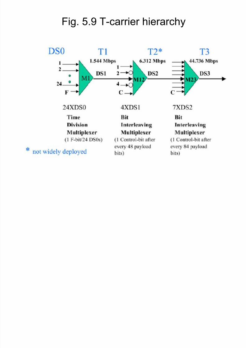
Multiplexing in North America
24 DS0 signals + a framing F -bit level 1 multiplexer (M1 ) a DS1 signal4 DS1 signals + a control C-bit ( for every 48 payload bits) bit interleaved by a level 1-to-2 multiplexer ( M12 ) a
DS2 signal7 DS2 signals + a control C-bit ( for every 84 payload bits) bit interleaved by a level 2-to-3 multiplexer ( M23 ) aDS3 signalTwo-stage multiplexing : multiplexing from DS1 to DS3
DS2, although defined, are seldom used. Instead, an M13multiplexer is used that multiplexes in one-stage 28 DS1signals and all the F -bits, C-bits into a DS3 signal with bitrate of 44.736 Mbps.
8/7/2019 Payload 4(Part1)
http://slidepdf.com/reader/full/payload-4part1 35/100
F ig. 5.9 T-carrier hierarchy

8/7/2019 Payload 4(Part1)
http://slidepdf.com/reader/full/payload-4part1 36/100
Stuffing Bits
A DS2 signal is formed by bit interleaving 4 DS1 signalso In a recurrent manner, a bit from each of the 4 DS1¶s is
placed ina sequential order But the four DS1 signal sources may be a slightly different
bit rage then the expected 1.544 MbpsStuffing additional bits in specfic time slots of slower DS1signal so that the composite DS2 signal is exactly 6.183MbpsStuffing bits are also used when 7 DS2 signals are
multiplexing into a DS3 signals

8/7/2019 Payload 4(Part1)
http://slidepdf.com/reader/full/payload-4part1 37/100
F ig. 5.10 DS2 frame ( 6.312 Mbps ) withBit Stuffing

8/7/2019 Payload 4(Part1)
http://slidepdf.com/reader/full/payload-4part1 38/100
F ig. 5.11 DS3 frame ( 44.736 Mbps ) withBit Stuffing

8/7/2019 Payload 4(Part1)
http://slidepdf.com/reader/full/payload-4part1 39/100
T1c Rate
Another legacy system format.2 DS1 signals and a control bit ( C-bit ) a M11c bit-interleaved multiplexer a DS1c signalDS1c signal uses a duo-binary modulation and in effect
doubles the bandwidth capacity of a T1 line

8/7/2019 Payload 4(Part1)
http://slidepdf.com/reader/full/payload-4part1 40/100
F ig. 5.12 T-carrier hierarchy

8/7/2019 Payload 4(Part1)
http://slidepdf.com/reader/full/payload-4part1 41/100
Multiplexing in Europe
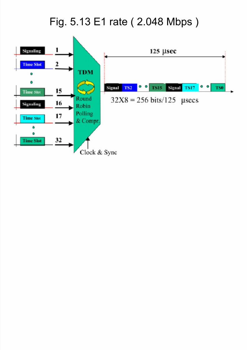
European systems time-division multiplex 30 user time slots andone ( framing and signaling ) time slot for every 15 user timeslots to yield an E1 ( or E11 ) frame with 32 time slots.The functions of the multiplexer are round-robin polling, byteinterleaving, and time compression.In the receiving end, an E1 signal is demultiplexed into 30 user channels and 2 added channels for framing and signaling andeach channel is decompressed to 64 Kbps.Each frame is transmitted within 125 s, so the total bit rate is2.048 Mbps.
E1 is different from DS1 in bit rate and also the absence of theF
-bit.E1 signal uses an alternate mark inversion ( AM I ) with a high-density bipolar three-zero ( HDB3 ) techniques.
8/7/2019 Payload 4(Part1)
http://slidepdf.com/reader/full/payload-4part1 42/100
F ig. 5.13 E1 rate ( 2.048 Mbps )
8/7/2019 Payload 4(Part1)
http://slidepdf.com/reader/full/payload-4part1 43/100
Multiplexing in Europe
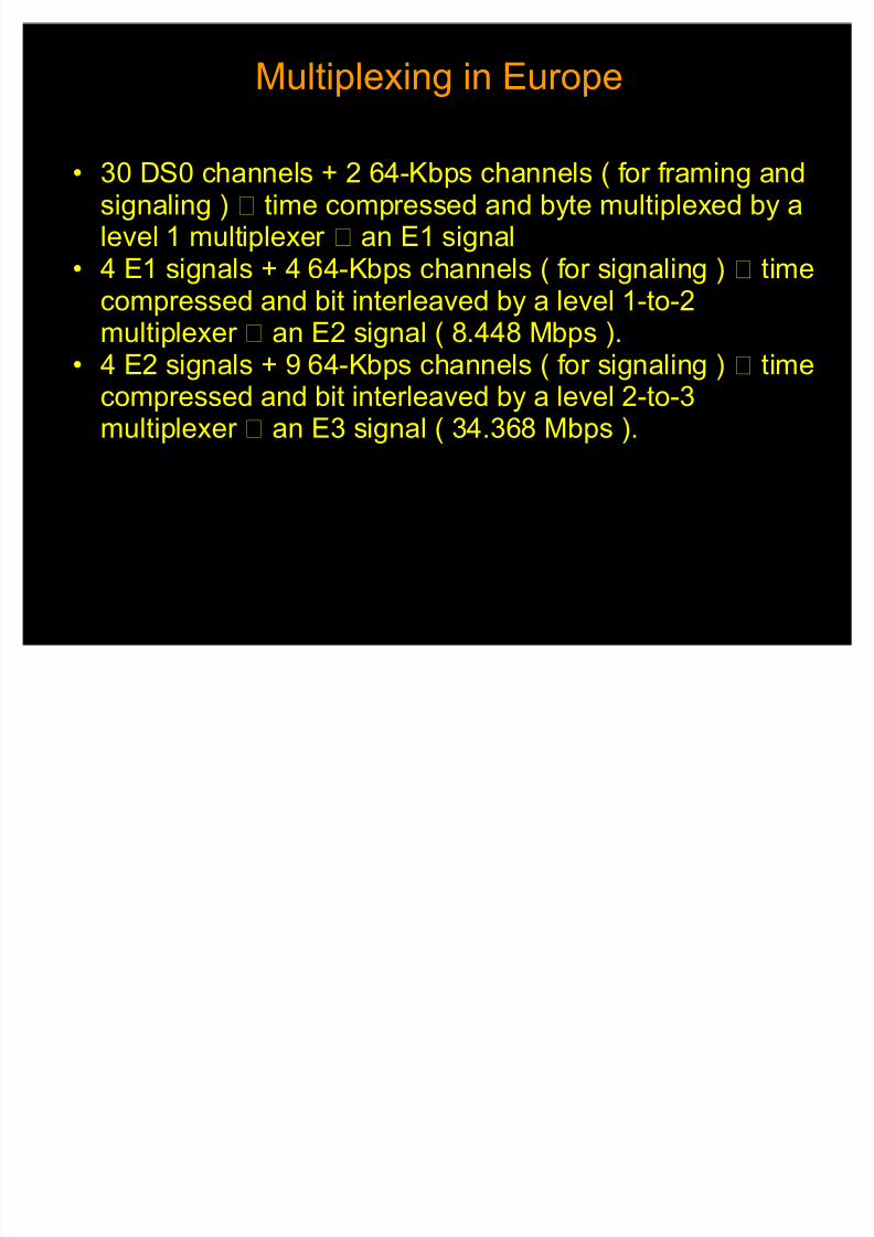
30 DS0 channels + 2 64-Kbps channels ( for framing andsignaling ) time compressed and byte multiplexed by alevel 1 multiplexer an E1 signal4 E1 signals + 4 64-Kbps channels ( for signaling ) time
compressed and bit interleaved by a level 1-to-2multiplexer an E2 signal ( 8.448 Mbps ).4 E2 signals + 9 64-Kbps channels ( for signaling ) timecompressed and bit interleaved by a level 2-to-3multiplexer an E3 signal ( 34.368 Mbps ).

8/7/2019 Payload 4(Part1)
http://slidepdf.com/reader/full/payload-4part1 44/100
F ig. 5.14 European hierarchy

8/7/2019 Payload 4(Part1)
http://slidepdf.com/reader/full/payload-4part1 45/100
Table 5.4 Legacy Rates
397.2 Mbps
274.176 MbpsDS4
139.264 MbpsE397.728 Mbps
91.053 MbpsDS3c
34.368 Mbps44.736 MbpsDS3
32.064 Mbps8.448 MbpsE2
6.312 Mbps6.312 MbpsDS2
3.152 Mbps3.152 MbpsDS1c
2.048 Mbps-E1
1.544 Mbps-1.544 MbpsDS1
64 Kbps64 Kbps64 KbpsDS0
JapanEuropeUnited StatesF acility

8/7/2019 Payload 4(Part1)
http://slidepdf.com/reader/full/payload-4part1 46/100
P ROS and CONS of Legacy Networks
Legacy networks were initially designed to carry voicesignal from many sources to many destinations.Switching functions play very important role in the legacynetworks.
Due to the circuit-switching nature, time slots areassigned to a particular user for as long as the connectionis alive, therefore the system is deterministic and itsdesign simpler.P re-assigned time slots uses bandwidth inefficiently
So, legacy networks do not cost-effectively accommodatehigh-bit-rate services

8/7/2019 Payload 4(Part1)
http://slidepdf.com/reader/full/payload-4part1 47/100
5.1 Legacy Communications Systems:Concepts
Legacy Data Networks
8/7/2019 Payload 4(Part1)
http://slidepdf.com/reader/full/payload-4part1 48/100
Legacy Data Networks
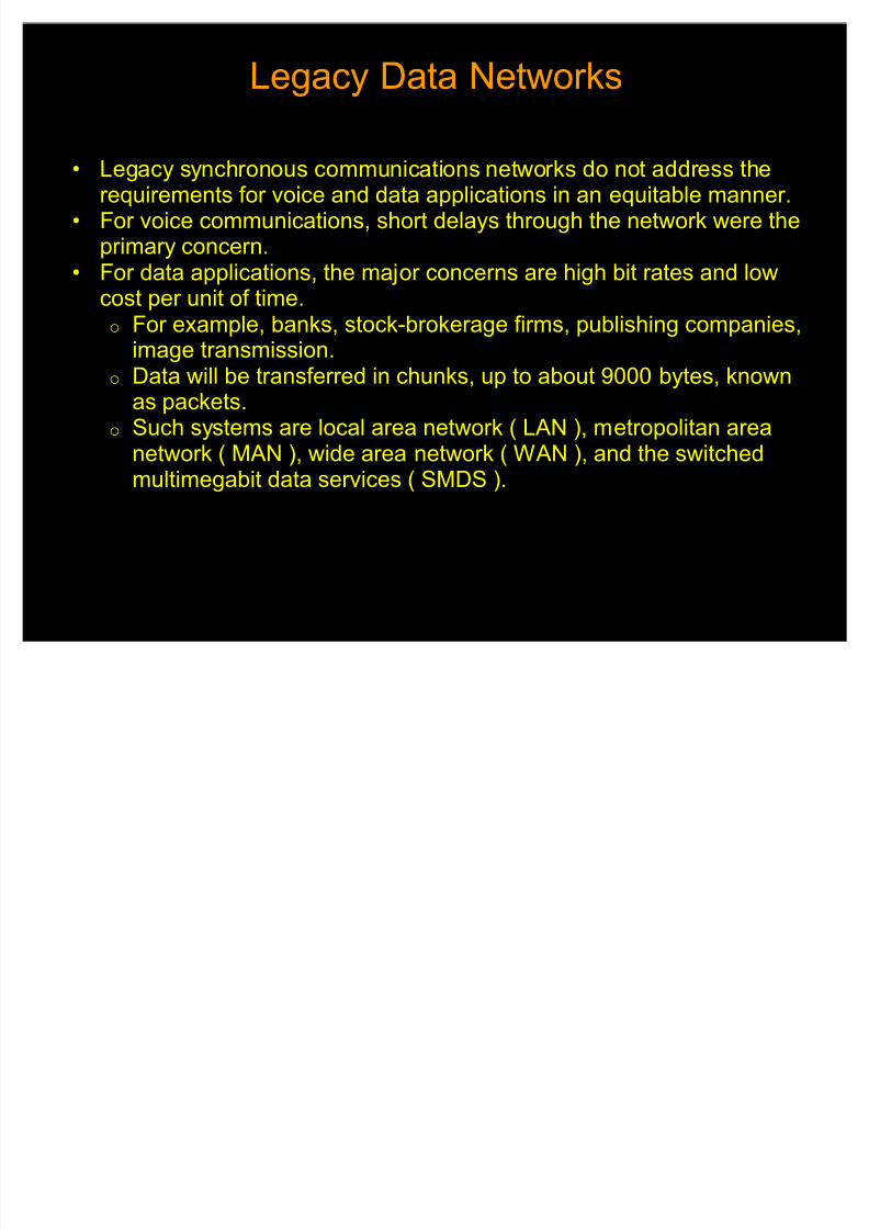
Legacy synchronous communications networks do not address therequirements for voice and data applications in an equitable manner.F or voice communications, short delays through the network were theprimary concern.F or data applications, the major concerns are high bit rates and lowcost per unit of time.
o F or example, banks, stock-brokerage firms, publishing companies,image transmission.
o Data will be transferred in chunks, up to about 9000 bytes, knownas packets.
o Such systems are local area network ( LAN ), metropolitan area
network ( MAN ), wide area network ( WAN ), and the switchedmultimegabit data services ( SMDS ).
8/7/2019 Payload 4(Part1)
http://slidepdf.com/reader/full/payload-4part1 49/100
LAN
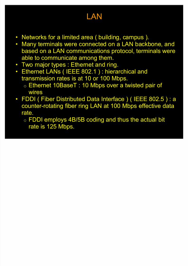
Networks for a limited area ( building, campus ).Many terminals were connected on a LAN backbone, andbased on a LAN communications protocol, terminals wereable to communicate among them.
Two major types : Ethernet and ring.Ethernet LANs ( IEEE 802.1 ) : hierarchical andtransmission rates is at 10 or 100 Mbps.
o Ethernet 10BaseT : 10 Mbps over a twisted pair of wires
F DD I ( F iber Distributed Data Interface ) ( IEEE 802.5 ) : acounter-rotating fiber ring LAN at 100 Mbps effective datarate.
o F DD I employs 4B/5B coding and thus the actual bitrate is 125 Mbps.

8/7/2019 Payload 4(Part1)
http://slidepdf.com/reader/full/payload-4part1 50/100
MAN
LANs were expanded to cover a city or a metropolis andthe MAN is evolvedTraffic from one LAN was brought to another via afunction known as bridge.
LAN/MAN traffic was routed on the communicationsnetworks so that connectivity between 2 or more remoteLANs/MANs could be established.Dedicated links can be deployed if high traffics betweentwo LANs/MANs is sustained 24 hours a day.

8/7/2019 Payload 4(Part1)
http://slidepdf.com/reader/full/payload-4part1 51/100
SMDS
A public MAN service developed by BellcoreP rimarily for LAN interconnections.Based on the distributed queue dual bus ( DQDB)transport and multiplexing mechanism and is defined inIEEE 802.6.The use of the DQDB format is based on a 53-byte cell
structure that is similar to the ATM cell.SMDS is a connectionless technology specified over synchronous carriers like DS1, DS3, E1 and E3 lines.
8/7/2019 Payload 4(Part1)
http://slidepdf.com/reader/full/payload-4part1 52/100
F rame Relay ( F R )
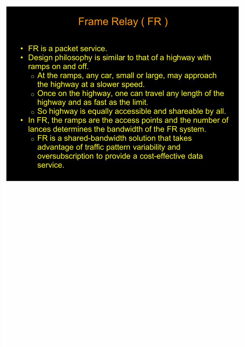
F R is a packet service.Design philosophy is similar to that of a highway withramps on and off.
o At the ramps, any car, small or large, may approach
the highway at a slower speed.o Once on the highway, one can travel any length of thehighway and as fast as the limit.
o So highway is equally accessible and shareable by all.In F R, the ramps are the access points and the number of
lances determines the bandwidth of the F R system.o F R is a shared-bandwidth solution that takes
advantage of traffic pattern variability andoversubscription to provide a cost-effective dataservice.

8/7/2019 Payload 4(Part1)
http://slidepdf.com/reader/full/payload-4part1 53/100
F rame Relay ( F R )
At the access points, or the user-to-network interface,circuitry concentrates the packet traffic from a number of users, typically over leased lines ( T1 / E1 ).The concentrated traffic is switched by means of a F R
switch and it is put on a common backbone ( the highway).A number of F R switches are interconnected to form a F Rnetwork.

8/7/2019 Payload 4(Part1)
http://slidepdf.com/reader/full/payload-4part1 54/100
5.2 SONET and SDH
Introduction

8/7/2019 Payload 4(Part1)
http://slidepdf.com/reader/full/payload-4part1 55/100
Introduction
The evolution from copper wires to optical fibers led too Synchronous Optical Network ( SONET ) in USo Synchronous Digital Hierarchy ( SDH ) in Europeo Since first deployment in the 1980s, SONET / SDH
have almost replaced all long-haul copper cables.o The optical fiber has responded to an unexpectedincrease in traffic demand and make ³ informationsuperhighway ³ a reality
8/7/2019 Payload 4(Part1)
http://slidepdf.com/reader/full/payload-4part1 56/100
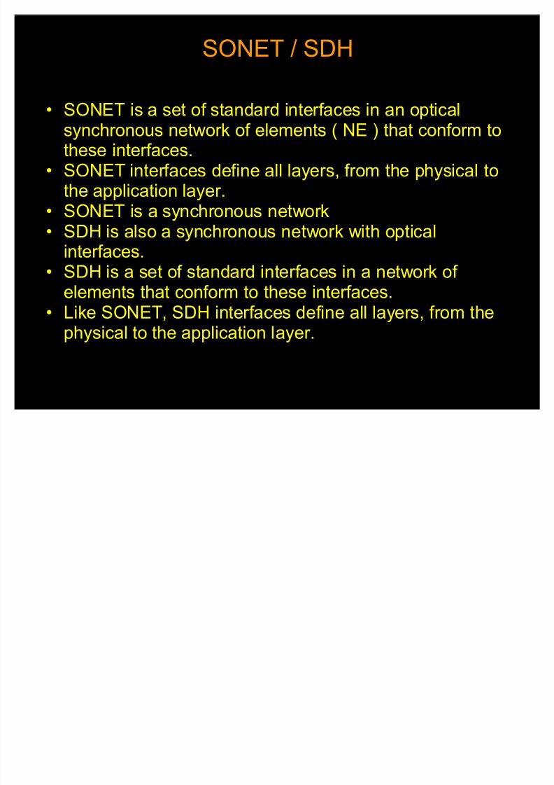
SONET / SDH
SONET is a set of standard interfaces in an opticalsynchronous network of elements ( NE ) that conform tothese interfaces.SONET interfaces define all layers, from the physical to
the application layer.SONET is a synchronous networkSDH is also a synchronous network with opticalinterfaces.SDH is a set of standard interfaces in a network of
elements that conform to these interfaces.Like SONET, SDH interfaces define all layers, from thephysical to the application layer.
8/7/2019 Payload 4(Part1)
http://slidepdf.com/reader/full/payload-4part1 57/100
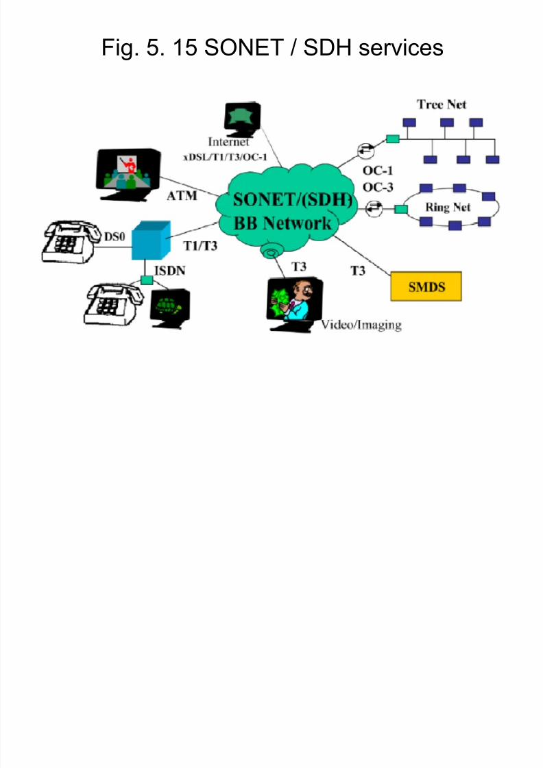
F ig. 5. 15 SONET / SDH services

8/7/2019 Payload 4(Part1)
http://slidepdf.com/reader/full/payload-4part1 58/100
SONET versus SDH
Technical similarities between SONET and SDHo Bit rates and frame format organizationo F rame synchronization schemeso Multiplexing and de-multiplexing ruleso Error controlMajor differences :
o The variations about overhead bytes to accommodate differencesbetween US and European communications nodes and networks
o The SDH photonic interface specifies more parameters thanSONET
o SONET and SDH have enough minor technical and linguistic
differences to add complexity ( and cost ) in their design

8/7/2019 Payload 4(Part1)
http://slidepdf.com/reader/full/payload-4part1 59/100
SONET versus SDH
Some nomenclature exampleso Synchronous transport signal ( STS ) versus
synchronous transport module ( STM ), e.g., STS-1,STS-3, STS-12, STS-48 versus STM-1, STM-4, STM-
16.o Synchronous payload envelope ( S P E ) versus virtualcontainer ( VC )
o Virtual tributary ( VT ) versus tributary unit ( TU )

8/7/2019 Payload 4(Part1)
http://slidepdf.com/reader/full/payload-4part1 60/100
SONET / SDH Benefits
Reduced cost:o It lowers operations costo It has the same interface for all vendors
Integrated network elementso I
t allows for multi-vendor internetworkingo It has enhanced network element managementRemote operations capabilities : provision, test, inventory,customize, and reconfiguredIt offers network survivability features.
It is compatible with legacy and future networks

8/7/2019 Payload 4(Part1)
http://slidepdf.com/reader/full/payload-4part1 61/100
SONET and SDH Rates
SONET and SDH rates are in the range of 51.85 ±9953.28 MbpsSONET signal in electrical nature : synchronous transportsignal level N ( STM-N )
SDH signal in electrical nature : synchronous transportmodule level N ( STM-N )In optical signal nature : optical carrier level N ( OC-N )

8/7/2019 Payload 4(Part1)
http://slidepdf.com/reader/full/payload-4part1 62/100
Table 5.5 SONET / SDH Rates

8/7/2019 Payload 4(Part1)
http://slidepdf.com/reader/full/payload-4part1 63/100
Why Use SONET / SDH ?
Why is glass fiber better than copper wire ?o Higher transmission reliability.
Glass fiber is not as susceptible to radio frequency or electromagneticinterference ( R FI , EM I ) as copper wire unless it is shielded and wellgrounded
o Lower bit error rate ( BER ) : lower inter-symbol interference amongfibers than copper wires, so lower bit error rate.
o Higher bandwidth per fiber o F iber can transmit without repeaters at longer distance compared to
copper wires.o F iber yields thinner cable than copper.o SONET/SDH is based on standards, which enables multivendor
compatibility and interoperability.
8/7/2019 Payload 4(Part1)
http://slidepdf.com/reader/full/payload-4part1 64/100

8/7/2019 Payload 4(Part1)
http://slidepdf.com/reader/full/payload-4part1 65/100

8/7/2019 Payload 4(Part1)
http://slidepdf.com/reader/full/payload-4part1 66/100
F ig. 5. 16 SONET network

8/7/2019 Payload 4(Part1)
http://slidepdf.com/reader/full/payload-4part1 67/100
Network Topologies
Three major network topologies : tree, ring, and meshTreeo A hierarchical distribution of NEso Most used in LANs, such as Etherneto A source is connected to a distribution function ( known
as hub ) that routes a source packet to its destinationnode.
o A connection between source and destination isestablished for the duration of the packet through the
hub.o Very efficient for asynchronous data transmission but
not for real-time data and voice.o If a hub fails, all connections through it die.

8/7/2019 Payload 4(Part1)
http://slidepdf.com/reader/full/payload-4part1 68/100
Network Topologies
Ring : consists of NEs interconnected with a dual fiber,the primary and secondary, to form a ring.
o Some of the NEs are also assigned to communicationwith other rings or topologies
o When one fiber fails, the other can still keep theintegrity of the ring
o If both fiber breaks, then the network is reconfigured,forming a ring using both the primary and secondaryand the packets will flow through all fibers but the
broken ones.o Ring offers fast path protection and is widely used in
LANs or within a relatively limited radius ( campus,town, high risers).

8/7/2019 Payload 4(Part1)
http://slidepdf.com/reader/full/payload-4part1 69/100
Network Topologies
Mesh : consists of NEs fully interconnectedo When one link breaks, the adjacent NE detects the
breakage and reroutes the traffic to another NE.o Mesh provides transmission protection and network
restoration capabilities.o Mesh also provides disaster avoidance capabilities
when a cluster of NEs may fail.o Better applicable in densely populated areas.SONET / SDH networks are based on ring topologies
Other topologies may be mixed into networks as well.

8/7/2019 Payload 4(Part1)
http://slidepdf.com/reader/full/payload-4part1 70/100
F ig. 5. 17 Ring, tree and mesh topologies

8/7/2019 Payload 4(Part1)
http://slidepdf.com/reader/full/payload-4part1 71/100
A Hierarchical P rocess
A hierarchical process can transformed any type of non-SONET signal into SONET networks.
1. Segmenting the signal and mapping the segments insmall containers known as virtual tributaries ( VTs ).
2. Once the VTs have been filled with segmented payload,they are grouped in larger containers that are know asgroups.
3. Groups are then mapped into a SONET frame.4. Many contiguous frames entails the SONET signals to be
transmitted over the OC-N fiber.In SDH, VT are called tributary units ( TUs ) and thegroups are called tributary unit groups ( TUGs ).

8/7/2019 Payload 4(Part1)
http://slidepdf.com/reader/full/payload-4part1 72/100
F ig. 5. 18 SONET hierarchy
8/7/2019 Payload 4(Part1)
http://slidepdf.com/reader/full/payload-4part1 73/100
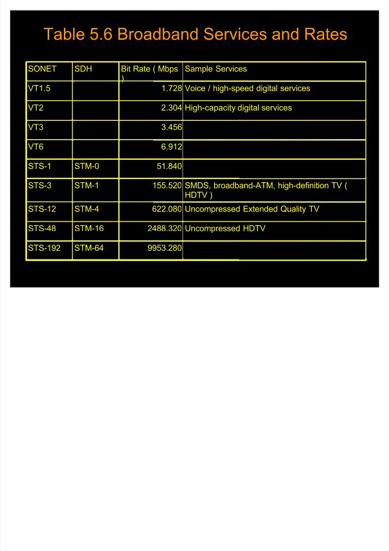
Table 5.6 Broadband Services and Rates
9953.280STM-64STS-192
Uncompressed HDTV2488.320STM-16STS-48
Uncompressed Extended Quality TV622.080STM-4STS-12
SMDS, broadband-ATM, high-definition TV (HDTV )
155.520STM-1STS-3
51.840STM-0STS-1
6.912VT6
3.456VT3
High-capacity digital services2.304VT2
Voice / high-speed digital services1.728VT1.5
Sample ServicesBit Rate ( Mbps)
SDHSONET

8/7/2019 Payload 4(Part1)
http://slidepdf.com/reader/full/payload-4part1 74/100
P ath, Line and Section
A SONET / SDH frame is transmitted from an end user toanother end user through nodes in the network.To ensure the deliverability and the integrity of the signal,overheads are added to the sending signal to be used for network administration purposes.This overhead information is transparent to end users.The overhead has been organized hierarchically in threetypes :
o P atho
Lineo Section

8/7/2019 Payload 4(Part1)
http://slidepdf.com/reader/full/payload-4part1 75/100
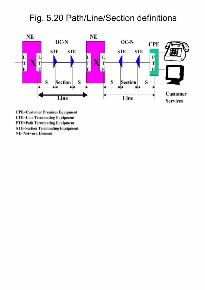
P ath, Line and Section
P ath : overhead added at transmitting path-terminating equipment (P TE ), and it is read by the receiving P TE.
o P ath information is not checked or altered by intermediateequipment
Line : overhead added by the transmitting line-terminating equipment (LTE ) to be used by the receiving LTE.
o At the edges of the networks, ( where there are no LTEs, ) P TEsplay the role of LTEs
Section : overhead added by equipment terminating a physicalsegment of the transmission facility.
o A segment between two repeaterso A segment between an LTE and a repeater o A segment between an P TE and a repeater o A segment between two adjacent LTEs where no repeaters
between them.o All these are sections.

8/7/2019 Payload 4(Part1)
http://slidepdf.com/reader/full/payload-4part1 76/100
F ig. 5.19 P ath/Line/Section definitions
8/7/2019 Payload 4(Part1)
http://slidepdf.com/reader/full/payload-4part1 77/100
F ig. 5.20 P ath/Line/Section definitions

8/7/2019 Payload 4(Part1)
http://slidepdf.com/reader/full/payload-4part1 78/100
5.2 SONET and SDH
SONET/SDH F rames

8/7/2019 Payload 4(Part1)
http://slidepdf.com/reader/full/payload-4part1 79/100
STS-1
The smallest SONET frameCan be visualized as a 2-dimensional matrix of 9 rows by90 columns, each entry is a byte.The whole STS-1 has 9 x 90 = 810 bytesThe first 3 columns : transport overhead for section andline.Synchronous P ayload Envelope ( S P E ) : the bytecapacity contained from the 4 th column to the last column,totally 87 columns or 783 bytes.P
ath overhead : the 4th
column.F ixed stuff : columns 30 and 59 of the STS-1.The actual payload capacity is 84 columns, i.e., 756 bytesor 48.384 Mbps effective bit rate.

8/7/2019 Payload 4(Part1)
http://slidepdf.com/reader/full/payload-4part1 80/100
F ig. 5.21 SONET STS-1 frame structure
8/7/2019 Payload 4(Part1)
http://slidepdf.com/reader/full/payload-4part1 81/100
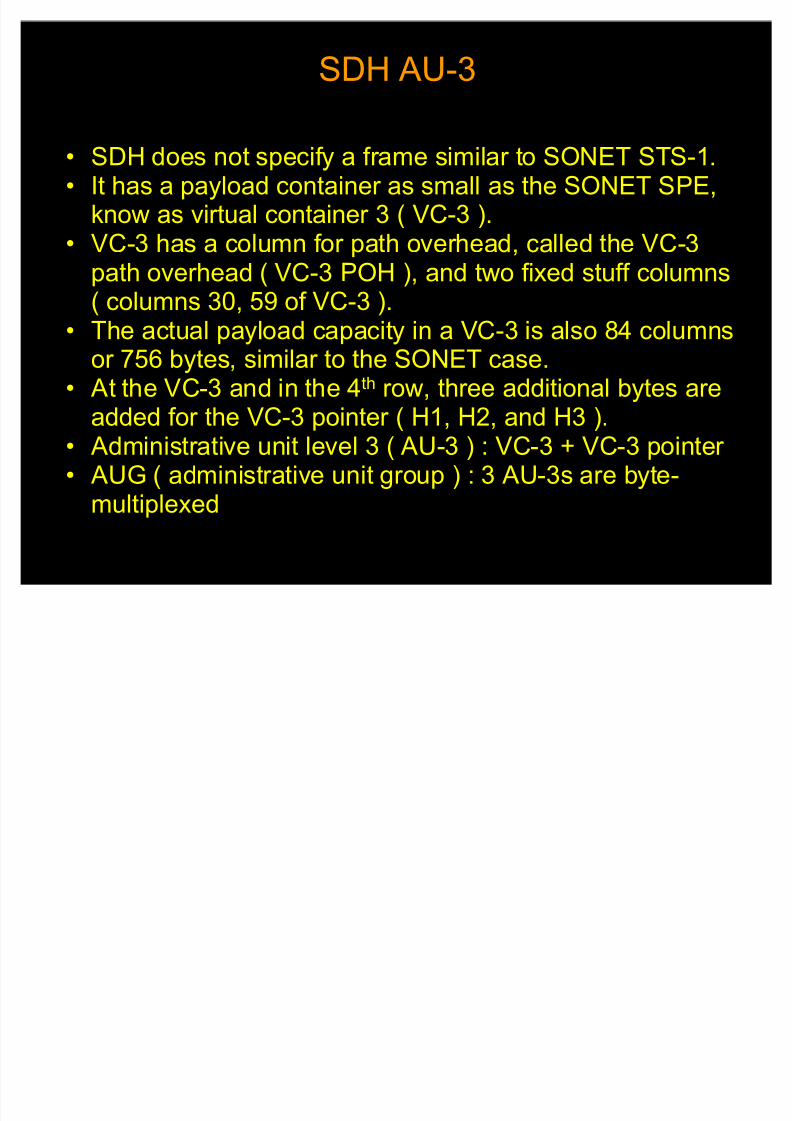
SDH AU-3
SDH does not specify a frame similar to SONET STS-1.It has a payload container as small as the SONET S P E,know as virtual container 3 ( VC-3 ).VC-3 has a column for path overhead, called the VC-3path overhead ( VC-3 P OH ), and two fixed stuff columns( columns 30, 59 of VC-3 ).The actual payload capacity in a VC-3 is also 84 columnsor 756 bytes, similar to the SONET case.At the VC-3 and in the 4 th row, three additional bytes are
added for the VC-3 pointer ( H1, H2, and H3 ).Administrative unit level 3 ( AU-3 ) : VC-3 + VC-3 pointer AUG ( administrative unit group ) : 3 AU-3s are byte-multiplexed
f

8/7/2019 Payload 4(Part1)
http://slidepdf.com/reader/full/payload-4part1 82/100
F ig. 5.22 SDH AU-3 frame structure

8/7/2019 Payload 4(Part1)
http://slidepdf.com/reader/full/payload-4part1 83/100
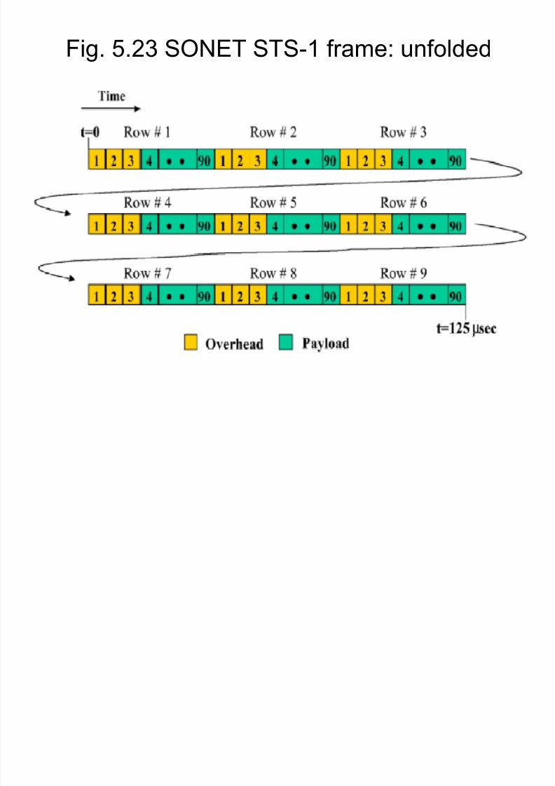
Transmitting an STS-1
To transmit an STS-1 over optical fibers, one starts withthe most significant bit ( MSB ) of the byte in column 1,row 1.Then when the byte is serially transmitted, it continueswith the byte in column 2, row 1; and so on.After the first row is transmitted, the process will transmitthe 2 nd row, and so on.In 125 s, all 6480 bits are transmitted, so the bit rate is51.86 Mbps.
F i 5 23 SONET STS 1 f f ld d
8/7/2019 Payload 4(Part1)
http://slidepdf.com/reader/full/payload-4part1 84/100
F ig. 5.23 SONET STS-1 frame: unfolded
F l i F

8/7/2019 Payload 4(Part1)
http://slidepdf.com/reader/full/payload-4part1 85/100
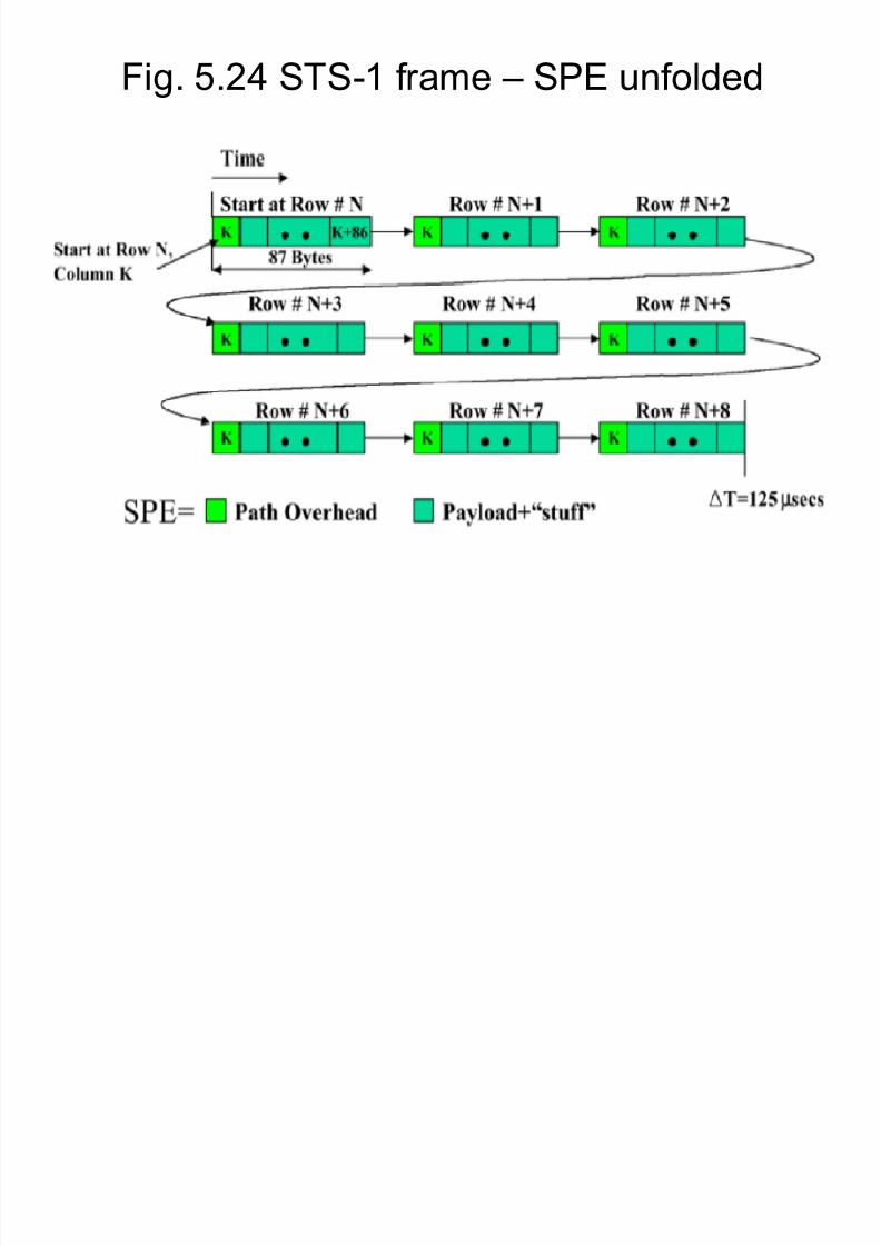
F loating F rames
SP E = user data + path overheadSTS-1 = S P E + line and section overheadWhen an STS-1 is received, the beginning of the frame isnot necessary synchronous with the beginning of theframe that the receiving node generates.The receiving node may need additional time to processthe overhead information.If the S P E waits for receiving node to synchronized, willsuffer added delays, which is bad for a high-speed
transmission network.So , the ³floating´ S P E technique is used to minimizeddelays.
F i 5 24 STS 1 f S P E f ld d
8/7/2019 Payload 4(Part1)
http://slidepdf.com/reader/full/payload-4part1 86/100
F ig. 5.24 STS-1 frame ± S P E unfolded
F l i F

8/7/2019 Payload 4(Part1)
http://slidepdf.com/reader/full/payload-4part1 87/100
F loating F rames
The process of an S P E is separated from the process of the line and section overhead of an STS-1.The received S P E may be out of phase ( in increments of bytes ) with the beginning of the STS-1 frame, which is insynchronization with the NE.This ³out of phase´ can be viewed as an offset in theSTS-1 frame, in terms of columns and rows.Thus, the first byte of the receiving S P E ( this will be thefirst byte of the path overhead ) is mapped in the S P E of
the current STS-1 frame on row N and column K, for example.As more bytes are received, the received S P E is wrappedaround the STS-1 S P E space.
F l ti F

8/7/2019 Payload 4(Part1)
http://slidepdf.com/reader/full/payload-4part1 88/100
F loating F rames
Resulting path overhead will be aligned in the K th column.Due to the offset, not all bytes of the received S P E will beable to fit in the S P E space of the current STS-1 frame.And the rest of the S P E will be mapped to the next STS-1S P E and each S P E are synchronous with the 125- sinterval.The end result will be an S P E mapped over twoconsecutive frames.
SONET STS 1 ith fl ti S

8/7/2019 Payload 4(Part1)
http://slidepdf.com/reader/full/payload-4part1 89/100
SONET STS-1 with floating S
Mapping a floating ( partial ) S P E in an

8/7/2019 Payload 4(Part1)
http://slidepdf.com/reader/full/payload-4part1 90/100
pp g g ( p )STS-1 frame
Mapping a floating ( complete ) S P E in

8/7/2019 Payload 4(Part1)
http://slidepdf.com/reader/full/payload-4part1 91/100
pp g g ( p )STS-1
Section Overhead : SONET

8/7/2019 Payload 4(Part1)
http://slidepdf.com/reader/full/payload-4part1 92/100
Section Overhead : SONET
The first 3 rows of the overhead space in an STS-1 frame, totally 9bytes, carry synchronization and section overhead information.A1 and A2 are fixed patterns : 0x F 628 or in binary 1111 0110 00101000. Receiver will use these to detect the beginning of the frame.
o A1, A2 are not scrambled.C1 : STS-1 ID, defined for each STS-1.B1 : used for error monitoring.E1 : a 64-Kbps voice communication channel for craft personnel.
o In an STS-N signal, E1 is defined for the 1 st STS-1 only. The other N-1 E1¶s are not used.
F 1 : used by the section.D1 to D3 : a 192-Kbps communication channel between STEs.
o Used for alarms, maintenance, control, monitoring, administration,and other communicaiton needs.
o In an STS-N signal, this channel is defined for the 1 st STS-1 only.The other N-1 E1¶s are not used.
STS 1 section overhead

8/7/2019 Payload 4(Part1)
http://slidepdf.com/reader/full/payload-4part1 93/100
STS-1 section overhead
Line Overhead : SONET

8/7/2019 Payload 4(Part1)
http://slidepdf.com/reader/full/payload-4part1 94/100
Line Overhead : SONET
Located in the row 4-9 of the overhead section, totally 45bytes.H1, H2 :offset between the pointer and the first S P E byte.H3 : an action byte for frequency justification.o It carries valid payload if the justification is negative.BIP -8 : Used for locating errors.o It is calculated using even parity over the STS-1 for the
previous frame after scrambling and placed in B2before scrambling the current frame.
K1, K2 : for automatic protection switching.o In STS-N, this is defined for #1 only.
STS 1 line overhead

8/7/2019 Payload 4(Part1)
http://slidepdf.com/reader/full/payload-4part1 95/100
STS-1 line overhead
Line Overhead : SONET

8/7/2019 Payload 4(Part1)
http://slidepdf.com/reader/full/payload-4part1 96/100
Line Overhead : SONET
D4 to D12 : a 576-Kbps communication channel between LTE for o Alarmso Maintenanceo Controlo Monitoringo
Administrationo Other communication needso In STS-N, this is defined for #1 onlyZ1, Z2 : not defined except in STS-N for #3, in which Z2 is onlydefined as line far-end block error ( F EBE ).E2 : an express 64-Kbps communications channel between LTEo In STS-N, this is defined for #1 only
P ayload P ointers : H1 H2 H3

8/7/2019 Payload 4(Part1)
http://slidepdf.com/reader/full/payload-4part1 97/100
P ayload P ointers : H1, H2, H3
NDF ( New Data F ound flag ) : first 4 MSB in the H1 byteo ³ normal = 0110 ³ for the following 3 possible situations :
No frequency justificationP ositive frequency justification has taken placeNegative frequency justification has taken place
o ³ set = 1001 ³: an arbitrary ( and significant ) change of the pointer
vaule has occurred due to a change of data position in the S P ES-bits : the size of the virtual tributary in the payloadI-bit / D-bit word : for incrementing / decrementing the offset
o P erform frequency justification in conjunction with the H3 byteH3 : a payload byte opportunity buffer when positive or negative
justifications are necessary
P ayload pointers : H1 and H2

8/7/2019 Payload 4(Part1)
http://slidepdf.com/reader/full/payload-4part1 98/100
P ayload pointers : H1 and H2
P ointer H3 ± frequency justification

8/7/2019 Payload 4(Part1)
http://slidepdf.com/reader/full/payload-4part1 99/100
P ointer H3 ± frequency justification
F unctions of H1 H2 and H3

8/7/2019 Payload 4(Part1)
http://slidepdf.com/reader/full/payload-4part1 100/100
F unctions of H1, H2 and H3
Identifies that a change has occurred in the pointer value ( ND F = 1001 ) due to an intermittent synchronization in the node wherethe new start is ( I + D bits ).Identifies that a change may have occurred in the pointer value (0110 ) due to a frequency difference between node and incoming
frequency.o Received frequency may be slightly higher or lower than the
node frequency.o Either more or fewer bits are received that what the S P E can
fit.o If the received frequency is higher ( lower ), then node will
perform a negative ( positive ) frequency justification.The I-bit / D-bit words value will indicate whether negative or positive frequency justification is needed.