pavement design and materials (papagiannakis/pavement design and materials) || pavement...
TRANSCRIPT
13PavementRehabilitation
13.1 Introduction
Pavement rehabilitation refers to the broad range of treatmentsfor repair, rehabilitation, restoration and replacement of pave-ments, colloquially referred as the 4-Rs. Historically, these treatmentsexcluded routine maintenance activities (e.g., pothole filling), whichdid not qualify for federal fund sharing. This is no longer thecase, provided that agencies can document that maintenance iscost-effective in preserving pavements between more comprehensive4-R treatments.10,11 Restoration refers to a variety of surface treat-ments such as crack filling and coating, while resurfacing includeschip sealing and overlaying with either asphalt concrete or port-land concrete. Recycling consists mainly of incorporating reclaimedasphalt pavement (RAP) into new asphalt concrete. Reconstructionis, in essence, new construction for which design methods weredescribed earlier in this book (Chapters 11 and 12).
Typically, rehabilitation is triggered using pavement distress crite-ria (e.g., reaching threshold values in particular distresses) or sometype of aggregate distress index reflecting the type of distressespresent and their extent/severity (e.g., the PCI index describedin Chapter 9). Some jurisdictions utilize pavement roughness ora combined index of distress and roughness as an alternative
451Pavement Design and Materials A. T. Papagiannakis and E. A. MasadCopyright © 2008 John Wiley & Sons, Inc.
452 13 Pavement Rehabilitation
rehabilitation-triggering criterion. In addition, there are circum-stances where pavement rehabilitation is triggered by safety ratherthan distress/roughness considerations (e.g., the need to increasepavement texture in order to improve skid resistance).
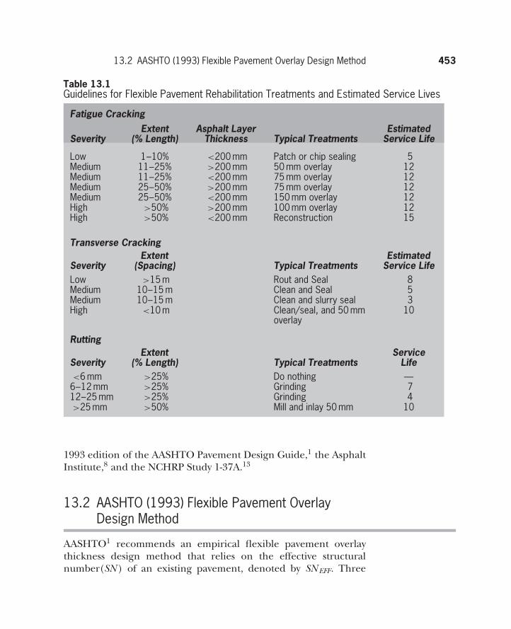
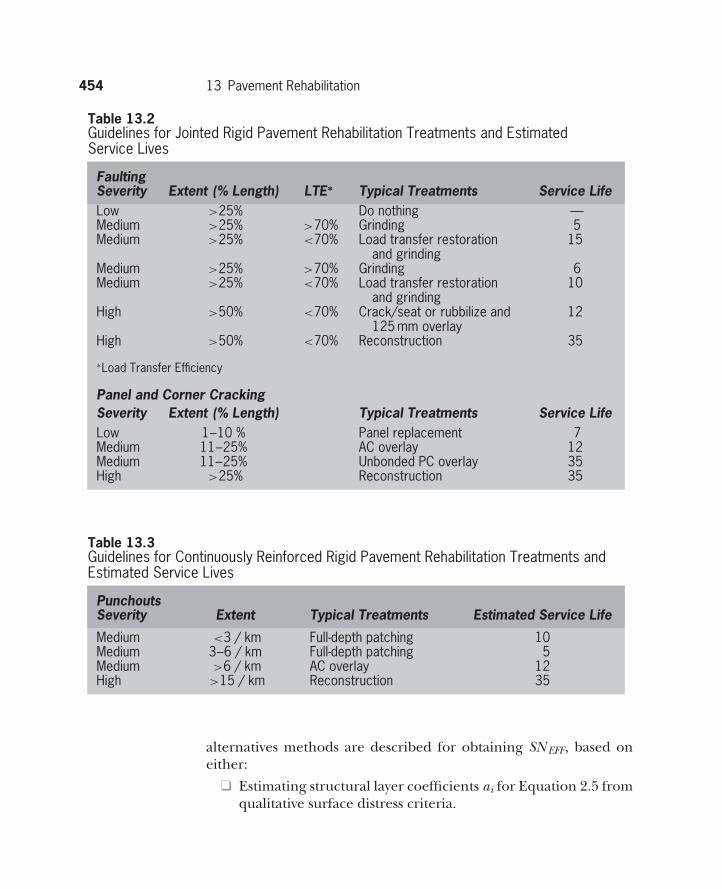
The range of feasible 4-R treatments depends on pavementcondition, as defined by the type of distresses present and theirextent/severity, as well as the degree of structural strengtheningnecessary. Ideally, the best among the feasible 4-R treatments shouldbe selected on the basis of life-cycle cost analysis (LCCA) describedin Chapter 14. General 4-R treatment guidelines for a selected set ofcircumstances are shown in Tables 13.1, 13.2, and 13.3 for asphaltconcrete pavements, jointed portland concrete pavements, (eitherJPCP or JDRCP), and continuously reinforced portland concretepavements (CRCP), respectively. These tables provide estimates ofthe expected service lives of these treatments. Their actual servicelives may vary significantly from these estimates, depending on theparticular traffic/environmental circumstances and constructionquality.
The focus of this chapter is on overlays and their design method-ologies. Regardless of the design methodology and the materialsinvolved, the existing pavement surface needs to be prepared torepair distresses that, if left untreated, may compromise the perfor-mance of the overlay. This is especially true in portland concretepavements, where the surface needs to be treated to control reflec-tion cracking. This involves either fracturing of the entire surfaceor keeping the surface intact while effecting full-depth repairs/slabreplacement at particularly deteriorated locations.9 Fracturing anexisting portland concrete pavement in preparation for an overlayis cost-effective where the existing portland concrete surface is badlydistressed. It is carried out by either rubbilizing (i.e., mechanicallyfracturing slabs into pieces smaller than 0.3 m), cracking/seating(i.e., breaking slabs into 0.3 to 1.0 m pieces), or breaking/seating(i.e., breaking the slabs into 0.3 to 1.0 m pieces and ensuring thatthe bond between concrete and rebar reinforcement is also bro-ken). The fracturing method is dictated by portland concrete type:cracking/seating is suited for JPCPs; breaking/seating is suited toJDRPCs; and rubbilizing suits all portland concrete types, includingCRCPs. Overlay design requires special care in identifying the lim-its of the pavement sections to be overlaid, so they have uniformage, surface condition, traffic level, and structural characteristics.The overlay design methods described next are attributed to the
13.2 AASHTO (1993) Flexible Pavement Overlay Design Method 453
Table 13.1Guidelines for Flexible Pavement Rehabilitation Treatments and Estimated Service Lives
Fatigue CrackingExtent Asphalt Layer Estimated
Severity (% Length) Thickness Typical Treatments Service Life
Low 1–10% <200 mm Patch or chip sealing 5Medium 11–25% >200 mm 50 mm overlay 12Medium 11–25% <200 mm 75 mm overlay 12Medium 25–50% >200 mm 75 mm overlay 12Medium 25–50% <200 mm 150 mm overlay 12High >50% >200 mm 100 mm overlay 12High >50% <200 mm Reconstruction 15
Transverse CrackingExtent Estimated
Severity (Spacing) Typical Treatments Service LifeLow >15 m Rout and Seal 8Medium 10–15 m Clean and Seal 5Medium 10–15 m Clean and slurry seal 3High <10 m Clean/seal, and 50 mm 10
overlay
RuttingExtent Service
Severity (% Length) Typical Treatments Life<6 mm >25% Do nothing —
6–12 mm >25% Grinding 712–25 mm >25% Grinding 4>25 mm >50% Mill and inlay 50 mm 10
1993 edition of the AASHTO Pavement Design Guide,1 the AsphaltInstitute,8 and the NCHRP Study 1-37A.13
13.2 AASHTO (1993) Flexible Pavement OverlayDesign Method
AASHTO1 recommends an empirical flexible pavement overlaythickness design method that relies on the effective structuralnumber(SN ) of an existing pavement, denoted by SN EFF. Three
454 13 Pavement Rehabilitation
Table 13.2Guidelines for Jointed Rigid Pavement Rehabilitation Treatments and EstimatedService Lives
FaultingSeverity Extent (% Length) LTE∗ Typical Treatments Service LifeLow >25% Do nothing —Medium >25% >70% Grinding 5Medium >25% <70% Load transfer restoration
and grinding15
Medium >25% >70% Grinding 6Medium >25% <70% Load transfer restoration
and grinding10
High >50% <70% Crack/seat or rubbilize and125 mm overlay
12
High >50% <70% Reconstruction 35
∗Load Transfer Efficiency
Panel and Corner CrackingSeverity Extent (% Length) Typical Treatments Service LifeLow 1–10 % Panel replacement 7Medium 11–25% AC overlay 12Medium 11–25% Unbonded PC overlay 35High >25% Reconstruction 35
Table 13.3Guidelines for Continuously Reinforced Rigid Pavement Rehabilitation Treatments andEstimated Service Lives
PunchoutsSeverity Extent Typical Treatments Estimated Service Life
Medium <3 / km Full-depth patching 10Medium 3–6 / km Full-depth patching 5Medium >6 / km AC overlay 12High >15 / km Reconstruction 35
alternatives methods are described for obtaining SN EFF, based oneither:
❑ Estimating structural layer coefficients ai for Equation 2.5 fromqualitative surface distress criteria.
13.2 AASHTO (1993) Flexible Pavement Overlay Design Method 455
01020304050
Remaining Life, RL, percent
607080901000.5
0.6
0.7
0.8
0.9
Condition Factor, CF1.0
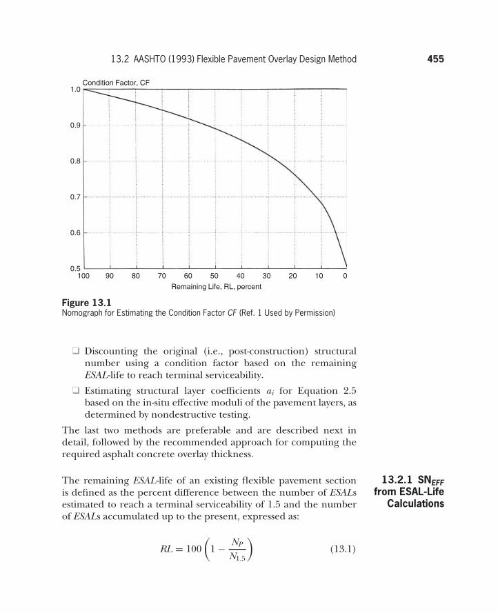
Figure 13.1Nomograph for Estimating the Condition Factor CF (Ref. 1 Used by Permission)
❑ Discounting the original (i.e., post-construction) structuralnumber using a condition factor based on the remainingESAL-life to reach terminal serviceability.
❑ Estimating structural layer coefficients ai for Equation 2.5based on the in-situ effective moduli of the pavement layers, asdetermined by nondestructive testing.
The last two methods are preferable and are described next indetail, followed by the recommended approach for computing therequired asphalt concrete overlay thickness.
13.2.1 SNEFFfrom ESAL-Life
Calculations
The remaining ESAL-life of an existing flexible pavement sectionis defined as the percent difference between the number of ESALsestimated to reach a terminal serviceability of 1.5 and the numberof ESALs accumulated up to the present, expressed as:
RL = 100(
1 − NP
N1.5
)(13.1)
456 13 Pavement Rehabilitation
where RL is the remaining life, and N p and N 1.5 are the accumulatedESALs to the present and to terminal serviceability, respectively. Thenomograph shown in Figure 13.1 is used to compute the conditionfactor (CF ), which allows computing the effective structural numberSN EFF of this section as:
SNEFF = CF SN0 (13.2)
where SN 0 is the original structural number of the pavement sectionpost-construction (i.e., Equation 2.5 with structural coefficientsuncompromised by age).
The required overlay thickness DOL is computed using:
DOL = SNF − SNEFF
a1(13.3)
where SN F is the structural number of a new pavement at this sitedesigned to sustain the future-life ESALs anticipated as computedusing the procedure described in Chapter 11. Typically, an a1 valueof 0.44 is used for new asphalt concrete layers.
Example 13.1 Determine the thickness of the asphalt concrete overlay requiredfor an existing pavement with asphalt concrete, unbound base andsubbase layer thicknesses of 18 cm, 15 cm and 20 cm (7, 5.9, and7.9 in.), respectively. The section has experienced 3.5 million ESALsto date; its serviceability is 2.5 in the PSI scale; and it is estimatedthat if left untreated, it could sustain another 1.5 million ESALsbefore its PSI reduces to a terminal value of 1.5. It is estimated thatthe overlaid pavement needs to have a structural number of 4.8 tosustain future traffic. The pavement layers drain within one day ifthey become saturated, which happens 10% of the time.
ANSWER
Draining within one day characterizes the drainage as ‘‘good’’(Table 10.1), which, combined with 10% of time saturation, allowsestimating drainage coefficients for the base and the subbase layersof 1.1 (Table 2.7). Hence, the original structural number of thesection postconstruction can be computed from Equation 2.5 as:
SN0 = 0.44 7 + 0.14 1.1 5.9 + 0.11 1.1 7.9 = 4.94
13.2 AASHTO (1993) Flexible Pavement Overlay Design Method 457
The remaining life factor is computed from Equation 13.1 as:
RL = 100(
1 − 3.55.0
)= 30%
Using a 30% remaining life, Figure 13.1 gives a condition fac-tor(CF ) of 0.82, which allows computing the effective structuralnumber SN EFF from Equation 13.2 as:
SNEFF = CF SN0 = 0.82 4.94 = 4.05
Given a required future structural number of 4.8, the overlaythickness can be computed from Equation 13.3 as:
DOL = SNF − SNEFF
a1= 4.8 − 4.05
0.44= 1.7 in to be rounded up 2 in (5 cm)
13.2.2 SNEFFfrom Non-
destructiveTesting Data
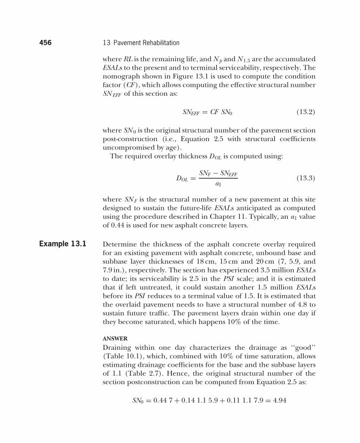
AASHTO1 describes an alternative method for establishing thestructural coefficients that give the effective structural number SN EFF.It is based on obtaining the resilient modulus of the subgrade Mrfrom pavement surface deflection measurements, and using thisvalue to compute an effective modulus of the pavement layers abovethe subgrade Ep. The subgrade resilient modulus is obtained froman expression derived from Equation 7.6 by setting the Poisson’sratio equal to 0.5:
Mr = 0.24 Pwr r
(13.4)
a
Subgrade
p
r
D
a2 + D30.7MR
Ep
wr
Figure 13.2Radial Offset for Subgrade-only Contribution to Surface Deflection
458 13 Pavement Rehabilitation
where wr is the deflection at a radial offset r from the centerline of theload of magnitude P . This radial offset should be sufficiently largeto ensure that only vertical strains within the subgrade contributeto the surface deflection being measured (Figure 13.2). As a result,the deflection beyond this offset is not temperature-sensitive.
The effective modulus of the layers above the subgrade Ep issubsequently computed through:
w0 = 1.5 p a
⎧⎪⎪⎪⎪⎪⎪⎪⎪⎪⎨⎪⎪⎪⎪⎪⎪⎪⎪⎪⎩
1
Mr
√√√√1 +(
Da
3
√EP
Mr
)2+
1 − 1√1 +
(Da
)2
Ep
⎫⎪⎪⎪⎪⎪⎪⎪⎪⎪⎬⎪⎪⎪⎪⎪⎪⎪⎪⎪⎭(13.5)
where w0 is the pavement surface deflection at the centerline of theloading plates the rest of the variables are defined in Figure 13.2.Note that the w0 deflection must be adjusted to correspond tothe reference temperature of 68◦F (20◦C). A procedure similarto the one described in Chapter 9 can be used for this purpose.Solving Equation 13.5 for Ep allows determining SN EFF using thenomograph shown in Figure 13.3. An example of this procedurefollows.
Example 13.2 A flexible pavement has asphalt concrete and base/subbase layerthicknesses of 15 and 25 cm (6 and 10 in), respectively. FWD mea-surements yielded deflections, corrected to 68◦F, of 0.015 and0.008 in, (0.038 and 0.02 cm) at radial offsets of 0 and 20 in, respec-tively. The load applied was 8,000 lbs (35.5 kN), and the radius ofthe loaded plate was 6 in (15 cm). Determine the SN EFF.
ANSWER
Use Equation 13.4 to compute the resilient modulus of the sub-grade:
Mr = 0.24 Pwr r
= 0.24 80000.008 20
= 12, 000 lb/in2 (82.7 MPa)
13.2 AASHTO (1993) Flexible Pavement Overlay Design Method 459
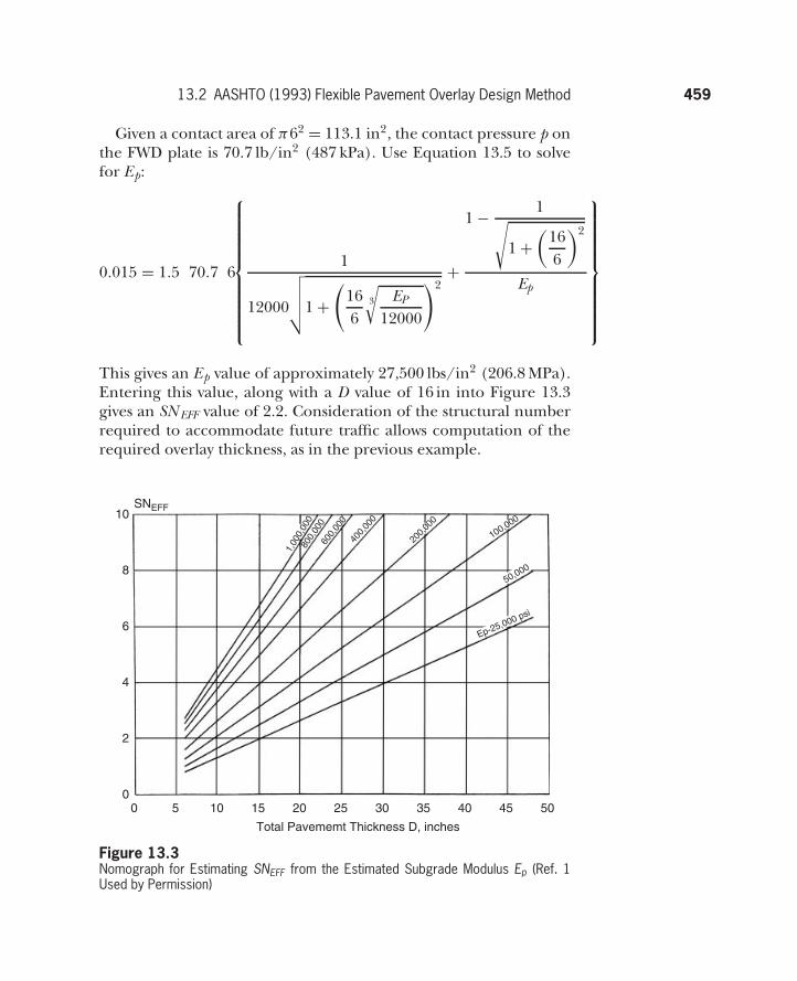
Given a contact area of π62 = 113.1 in2, the contact pressure p onthe FWD plate is 70.7 lb/in2 (487 kPa). Use Equation 13.5 to solvefor Ep:
0.015 = 1.5 70.7 6
⎧⎪⎪⎪⎪⎪⎪⎪⎪⎪⎨⎪⎪⎪⎪⎪⎪⎪⎪⎪⎩
1
12000
√√√√1 +(
166
3
√EP
12000
)2+
1 − 1√1 +
(166
)2
Ep
⎫⎪⎪⎪⎪⎪⎪⎪⎪⎪⎬⎪⎪⎪⎪⎪⎪⎪⎪⎪⎭
This gives an Ep value of approximately 27,500 lbs/in2 (206.8 MPa).Entering this value, along with a D value of 16 in into Figure 13.3gives an SN EFF value of 2.2. Consideration of the structural numberrequired to accommodate future traffic allows computation of therequired overlay thickness, as in the previous example.
00
2
4
6
8
10SNEFF
5 10 15 20
Total Pavememt Thickness D, inches
25 30 35 40 45 50
800,
000
400,
000
Ep-25,000 psi
50,000
100,000
200,
000
600,
000
1,00
0,00
0
Figure 13.3Nomograph for Estimating SNEFF from the Estimated Subgrade Modulus Ep (Ref. 1Used by Permission)
460 13 Pavement Rehabilitation
It should be noted that the methods just described for deter-mining flexible pavement overlay thickness represent a significantsimplification of the approach described in the 1986 edition of theAASHTO guide, which based SN EFF estimation on a combination ofremaining ESAL-life and structural considerations.
13.3 Asphalt Institute Flexible Pavement OverlayDesign Method
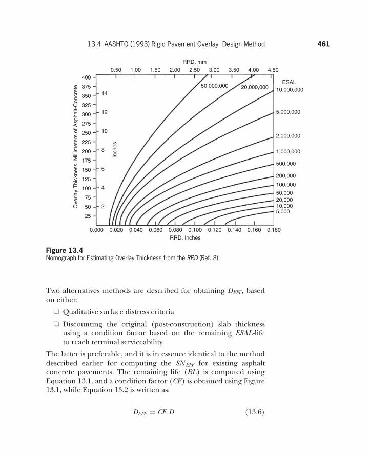
This method bases flexible pavement overlay thickness on the rep-resentative rebound deflection (RRD) of a section, obtained asexplained earlier (Chapter 9). Asphalt concrete overlay thickness isestimated as a function of the future anticipated ESALs over the lifeof the overlaid section, using the nomograph shown in Figure 13.4.8
Its use is explained through the following example.
Example 13.3 Design an overlay for the pavement deflection measurements andparticulars described earlier in Examples 9.6, 9.7, and 9.8.
ANSWER
The answer to Example 9.7 suggests an RRD of 1.735 mm (0.0068 in),which makes it structurally deficient (as described in Example 9.8,the SAI of this section was 2.0 on a scale of 0 to 10). Given thatthe traffic estimated over the future life of this section is 1 millionESALs, Figure 13.4 allows computing a required asphalt concreteoverlay thickness of 100 mm (4 in).
13.4 AASHTO (1993) Rigid Pavement OverlayDesign Method
AASHTO1 recommends an asphalt concrete overlay design method-ology over fractured portland concrete similar to the one describedfor overlaying existing asphalt concrete pavements. The fracturedportland concrete is simply treated as a high-strength granular baselayer.
The method AASHTO1 recommends for designing asphalt con-crete overlays over intact portland concrete pavements relies on theeffective slab thickness of the existing pavement, denoted by DEFF.
13.4 AASHTO (1993) Rigid Pavement Overlay Design Method 461
0.000
Ove
rlay
Thi
ckne
ss, M
illim
eter
s of
Asp
halt-
Con
cret
e
25
50 2
4
6
8
10
Inch
es12
14
75
100
125
150
175
200
225
250
275
300
325
350
375
4000.50 1.00 1.50 2.00
RRD, mm
2.50 3.00
50,000,000 20,000,000
3.50 4.00 4.50
0.020 0.040 0.060 0.080RRD. Inches
0.100 0.120 0.140 0.160 0.180
5,00010,00020,00050,000
100,000
200,000
500,000
1,000,000
2,000,000
5,000,000
10,000,000ESAL
Figure 13.4Nomograph for Estimating Overlay Thickness from the RRD (Ref. 8)
Two alternatives methods are described for obtaining DEFF, basedon either:
❑ Qualitative surface distress criteria
❑ Discounting the original (post-construction) slab thicknessusing a condition factor based on the remaining ESAL-lifeto reach terminal serviceability
The latter is preferable, and it is in essence identical to the methoddescribed earlier for computing the SN EFF for existing asphaltconcrete pavements. The remaining life (RL) is computed usingEquation 13.1. and a condition factor (CF ) is obtained using Figure13.1, while Equation 13.2 is written as:
DEFF = CF D (13.6)
462 13 Pavement Rehabilitation
where D is the as-built thickness of the portland concrete slab.Note that no method is described for obtaining DEFF from deflec-tion measurements. Instead, FWD measurements are used forback-calculating the modulus of subgrade reaction k and the mod-ulus of the existing portland concrete slab E . The back-calculationmethodology was described in detail in Chapter 9. It is suggested thatthe k values obtained with this method are roughly twice as large asthe values that would be obtained with a plate loading test, and needto be adjusted accordingly.1 In addition, where indirect tension dataon extracted cores are not available, the back-calculated modulusof the portland concrete slab E is used for indirectly estimating themodulus of rupture of the portland concrete, S ′
c using:
S ′C = 43.5
E106 + 488.5 (13.7)
where S ′c and E are in lbs/in2. Furthermore, FWD measurements are
used to obtain the load transfer efficiency (LTE) of joints. LTE valuesabove 70%, between 70% and 50%, and below 50% characterizeload transfer as good, fair, and poor, and are assigned load transfercoefficients (i.e., J values) of 3.2, 3.5, and 4, respectively. Thus,FWD measurements provide essential input data in determining thethickness of the future portland concrete slab, DF, following themethodology described in Chapter 12 (Equation 12.1).
The following describes the methodology used for computing theoverlay thickness for the most common types of overlays on portlandconcrete pavements, including asphalt concrete and portland con-crete, the latter being either bonded or unbonded. Bonded portlandconcrete overlays are constructed after a thin coat of cement groutor liquid epoxy is placed on the existing portland concrete pave-ment ahead of the paver.4 Unbonded portland concrete overlaysare constructed after a separation/debonding interlayer is placedon the existing portland concrete pavement surface.5 This interlayeris typically thin (25 to 50 mm) and consists of unbound aggregatesor asphalt concrete.
ASPHALT CONCRETE OVERLAYS
Asphalt concrete overlays on intact portland concrete pavementsneed to be constructed after the original portland concrete sur-face has been properly repaired. This includes full-depth repair of
13.4 AASHTO (1993) Rigid Pavement Overlay Design Method 463
cracked slabs and spalled joints and drainage improvement, fol-lowed by a tack coat prior to overlaying. The thickness of the asphaltconcrete overlay DOL required is computed using:
DOL = A (DF − DEFF ) (13.8)
where A is a function of structural deficiency obtained from:
A = 2.2233 + 0.0099 (DF − DEFF )2 − 0.1534 (DF − DEFF )
(13.9)
with the slab thicknesses in inches. The typical range in such overlaysis between 75 and 150 mm (3 to 6 in).
13.4.1 BondedPortland
ConcreteOverlays
Bonded portland concrete overlays are effective where the existingsurface has relatively low distress, which can be practically repairedbefore the overlay. The procedure recommended for determiningthe overlay thickness of a bonded portland concrete overlay is avariation of the flexible pavement overlay approach just described.The main difference is that instead of using Equation 13.8, theportland concrete overlay thickness is computed from:
DOL = DF − DEFF (13.10)
The typical range in this type of overlay is between 50 and 100 mm(2 to 4 in).
13.4.2 UnbondedPortland
ConcreteOverlays
Unbonded portland concrete overlays are effective where the exist-ing surface is badly deteriorated, and repairing it would be tooexpensive. Even so, a basic treatment of the surface and improve-ment of drainage are advisable. The overlay thickness is computedfrom:
DOL =√
DF − DEFF (13.11)
Example 13.4Design an asphalt concrete overlay for a jointed dowel-reinforcedrigid pavement 8 in thick (0.20 m). FWD measurements on thispavement yield a modulus of subgrade reaction of 140 lbs/in3
(38 MPa/m) and a portland concrete elastic modulus of 3,500,000lbs/in2 (24.8 MPa). In addition, FWD measurements across the
464 13 Pavement Rehabilitation
joints yield a LTE of 75%. Additional information given includes6.5 million ESALs accumulated to present and 8 million ESALsestimated to reduce PSI to 1.5. The number of future ESALs thatneeds to be carried over the design life of the overlaid section is7 million. Consider only traffic-related serviceability loss of 2.5,(4.5to 2.0). The standard error in predicting serviceability is 0.5, and thedesired reliability is 85%. The drainage condition for this section isconsidered good, with pavement layer saturation less frequent than10%.
ANSWER
Use Equation 12.1 to compute the required thickness of a portlandconcrete layer to carry future traffic, DF. Compute the necessaryinput from the information given. For 85% confidence, the value ofthe standard normal deviate Z R is − 1.037. The adjusted modulusof the subgrade reaction is 70 lbs/in3. The load transfer coefficientJ is 3.2, and the drainage coefficient Cd is 1.05 (Table 12.1). Themodulus of rupture of the portland concrete, S ′
c , is estimated fromEquation 13.7 as:
S ′C = 43.5 3.5 + 488.5 = 640 lbs/in2 (4412 kPa)
Substituting these values into Equation 12.1 allows solving for therequired thickness of the future pavement:
log(7 106) = −1.037 0.5 + 7.35 log(D + 1) − 0.06 +log
[2.5
4.5 − 1.5
]
1 + 1.624 107
(D + 1)8.46
+ (4.22 − 0.32 2) log640 1.05 (D0.75 − 1.132)
215.63 3.2[
D0.75 − 18.42(3.5 106/70)0.25
]
which gives a value of DF of 9.5 in (0.24 m).Compute the remaining life from Equation 13.1 as:
RL = 100(
1 − 6.58
)= 18.75%
13.5 NCHRP 1-37A Overlay Design Method 465
which gives a condition factor of 0.75 (Figure 13.1) and results ina DEFF value of 0.75 × 0.2 = 0.15 m (5.9 in) (Equation 13.6). Thecorrection factor A is computed from Equation 13.9.
A = 2.2233 + 0.0099 (9.5 − 5.9)2 − 0.1534 (9.5 − 5.9) = 1.8
Finally, the asphalt concrete overlay thickness is computed usingEquation 13.8.
DOL = 1.8 (9.5 − 5.9) = 6.4 in (0.165 m)
13.5 NCHRP 1-37A Overlay Design Method
The NCHRP 1-37A study13 describes a mechanistic-empiricalapproach to the design of asphalt concrete and portland con-crete overlays. The approach expands on the mechanistic responseand empirical damage function design approach presented earlierfor designing new pavements (Chapters 11 and 12). A key part ofthis overlay design approach is determining the properties of theexisting pavement layers. Three levels of detail are described forthis purpose, namely non-destructive testing (NDT), correlation toindex properties such as the California Bearing Ratio, and empiricalrelationships to surface distress. Only level 1 design involving NDTwill be described next, given the widely accepted use of this technol-ogy in designing overlays. The discussion treats separately asphaltconcrete overlays and portland concrete overlays. Each overlay typeis discussed separately as applied over existing flexible pavements,fractured portland concrete pavements, and intact portland con-crete pavements. The actual overlay alternative to be selected ineach circumstance should be decided on the basis of life-cycle costanalysis, as described in Chapter 14. The procedures described areunder review by another NCHRP Study.11 The outcome of thisreview and subsequent research is likely to result in modifications tosome of the design procedures described here.
13.5.1 AsphaltConcreteOverlays
Asphalt concrete is an effective overlay material for asphalt concretepavements, as well as portland concrete pavements. Asphalt concreteoverlaying of portland concrete requires considerable preparationof the existing surface to avoid reflection cracking, as describedearlier.
466 13 Pavement Rehabilitation
ASPHALT CONCRETE OVERLAYS OVER FLEXIBLE PAVEMENTS
The design of asphalt concrete overlays on asphalt concrete pave-ments involves determining the in-situ properties of the exist-ing pavement layers, including their in-situ elastic layer mod-uli, the amount of fatigue damage, and the amount of plasticdeformation experienced prior to the overlay. As described next,the fatigue damage in the asphalt concrete is estimated fromthe differences in dynamic moduli between the existing and theas-built layer, which is computed from extracted cores. The plasticdeformation of the pavement layers is measured directly throughtrenching.
The pavement layer elastic moduli are computed from NDT datathrough back-calculation techniques, as described in Chapter 9.The in-situ moduli of the granular layers need to be adjusted toaccount for the differences between field testing and laboratoryconditions. Typically, factors of 0.67 and 0.40 are used in convert-ing back-calculated moduli to resilient moduli (Mr) for granularbase and subgrade layers, respectively. The dynamic modulus of the‘‘damaged’’ asphalt concrete layer, back-calculated from NDT dataand denoted by E*dam, is used in combination with the ‘‘undam-aged’’ (i.e., as-built) dynamic modulus, denoted by E*, to estimatethe amount of fatigue damage accumulated. The master curve forE* is reconstructed from field core data (i.e., volumetric, gradation,and viscosity-temperature susceptibility data of the extracted binder,as described in Chapter 5). It allows estimating E* for the loadingrate/temperature conditions (i.e., reduced time) prevailing duringNDT. Knowing the E*dam and E* values under the same temper-ature/loading condition, allows computing the fatigue damage inthe asphalt concrete dAC prior to the overlay by solving the followingexpression:
E∗dam = Emin + E∗ − Emin
1 + e−0.3+5 log dAC(13.12)
where Emin is the minimum dynamic modulus for the asphalt con-crete, and the moduli are in lbs/in2. Note that Equation 13.12 is alsoused to compute further reductions in the modulus of the asphaltconcrete layer, as fatigue damage keeps accumulating throughoutthe life of the overlaid section.
13.5 NCHRP 1-37A Overlay Design Method 467
Example 13.5Compute the fatigue damage accumulated in an existing asphaltconcrete pavement, given that its E* and E*dam, computed as justdescribed, have values of 450,000 lb/in2 and 375,000 lb/in2 (3.1 GPaand 2.5 GPa), respectively, and the minimum E∗
min is 200,000 lb/in2
(1.37 GPa).
ANSWER
Substitute given moduli values into Equation 13.12 and solve it fordAC:
375000 = 200000 + 450000 − 2000001 + e−0.3+5 log dAC
which gives a dAC value of 0.77, or 77%.Successive trial performance simulations involving different over-
lay thicknesses are carried out to establish the minimum feasiblethickness that can accommodate future design life traffic. The cri-terion for the latter is predicting distresses below selected criticalthreshold values. The software developed by the NCHRP 1-37A studyis used for implementing this approach. In doing so, the proper-ties of the existing pavement layers, and their structural condition,obtained as described previously need to be specified.
ASPHALT CONCRETE OVERLAYS OVER FRACTURED PORTLANDCONCRETE PAVEMENTS
Asphalt concrete overlays over fractured portland concrete pave-ments require characterization of the underlying granular layersand the fractured portland concrete slabs. This involves deter-mining the moduli of the pavement layers, as well as the plas-tic deformation in the granular layers. The latter is obtaineddirectly through trenching. The moduli are computed throughback-calculation using NDT data, as described in Chapter 9. Theeffective modulus of the fractured portland concrete slab is com-puted as a function of the variability in the fracturing process.Table 13.4 shows the coefficient of variation in the back-calculatedslab piece moduli as a function of the quality of slab fractur-ing and the corresponding effective slab modulus. The latter wasobtained as the 25th percentile of the observed values.9 Usingthese effective moduli requires ensuring that no more than 5%
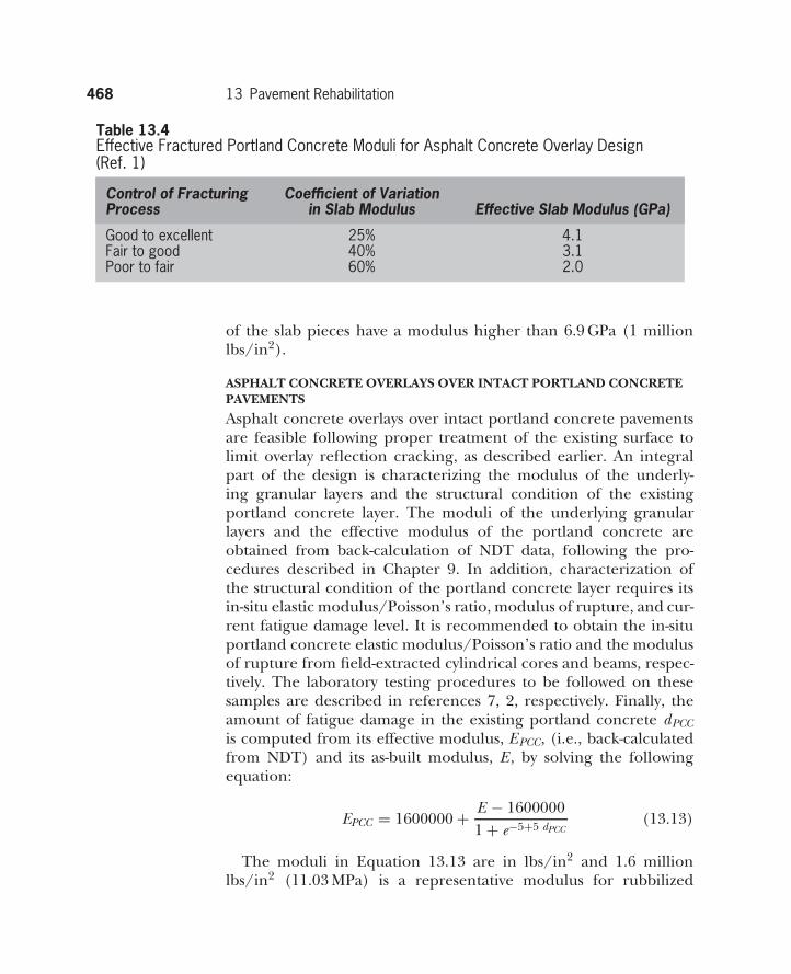
468 13 Pavement Rehabilitation
Table 13.4Effective Fractured Portland Concrete Moduli for Asphalt Concrete Overlay Design(Ref. 1)
Control of Fracturing Coefficient of VariationProcess in Slab Modulus Effective Slab Modulus (GPa)
Good to excellent 25% 4.1Fair to good 40% 3.1Poor to fair 60% 2.0
of the slab pieces have a modulus higher than 6.9 GPa (1 millionlbs/in2).
ASPHALT CONCRETE OVERLAYS OVER INTACT PORTLAND CONCRETEPAVEMENTS
Asphalt concrete overlays over intact portland concrete pavementsare feasible following proper treatment of the existing surface tolimit overlay reflection cracking, as described earlier. An integralpart of the design is characterizing the modulus of the underly-ing granular layers and the structural condition of the existingportland concrete layer. The moduli of the underlying granularlayers and the effective modulus of the portland concrete areobtained from back-calculation of NDT data, following the pro-cedures described in Chapter 9. In addition, characterization ofthe structural condition of the portland concrete layer requires itsin-situ elastic modulus/Poisson’s ratio, modulus of rupture, and cur-rent fatigue damage level. It is recommended to obtain the in-situportland concrete elastic modulus/Poisson’s ratio and the modulusof rupture from field-extracted cylindrical cores and beams, respec-tively. The laboratory testing procedures to be followed on thesesamples are described in references 7, 2, respectively. Finally, theamount of fatigue damage in the existing portland concrete dPCCis computed from its effective modulus, EPCC, (i.e., back-calculatedfrom NDT) and its as-built modulus, E , by solving the followingequation:
EPCC = 1600000 + E − 16000001 + e−5+5 dPCC
(13.13)
The moduli in Equation 13.13 are in lbs/in2 and 1.6 millionlbs/in2 (11.03 MPa) is a representative modulus for rubbilized
13.5 NCHRP 1-37A Overlay Design Method 469
portland concrete (i.e., a lower-limit value for an intact slab).Equation 13.13 is also used to reduce the modulus of the port-land concrete, with increasing fatigue damage in simulating theperformance of the asphalt concrete overlay.
13.5.2 PortlandConcreteOverlays
The NCHRP Study 1-37A13 includes design procedures for portlandconcrete overlays over existing flexible pavements, as well as rigidpavements, including JPCP/JDRCPs and CRCPs. The former, aresimilar to analyze/design as new portland concrete pavements withan asphalt concrete base, will not be further discussed here (seeChapter 12). Special provisions for constructing ultrathin portlandconcrete overlays over asphalt concrete pavements can be found inthe literature (e.g., reference 6). The following describes the designparticulars of portland concrete overlays over existing portlandconcrete pavements.
Portland concrete overlays can be either bonded or unbonded.Bonded portland concrete overlays involve no separation/debonding layer, hence can only match the configuration of theexisting rigid pavement. This means that jointed portland concreteoverlays are feasible only over an existing jointed portland concretepavement with the same joint configuration and spacing. Similarly,CRCP overlays are feasible only over existing CRCP pavements.The reason is that bonding between the old and the new surfacesprecludes relative movement of the two layers of slabs. On theother hand, unbonded portland concrete overlays involve a sepa-ration/debonding layer, hence allow relative movement of the twolayers of slabs. As a result, there is no reason for matching theconfiguration of the portland concrete overlay to that of the existingpavement.
The analysis/design approach for portland concrete overlays issimilar to the approach used for designing new rigid pavements.There are several differences, namely the need to describe thepavement layers and their structural properties, which includes theexisting layers, the new layer, and the interface layer (if one ispresent). The moduli for the existing pavement layers are bestobtained from back-calculation of NDT data and extracted samples,as described earlier. The damage functions for the overlaid structureare similar to the those described in Chapter 12. There are somedifferences in accounting for past damage in the existing layers (e.g.,
470 13 Pavement Rehabilitation
the fatigue damage involves an additional term to the one shown inEquation 12.13 to account for past damage in the existing layers).
References1 AASHTO (1993). AASHTO Guide for the Design of Pavement
Structures, American Association of State Highway and Trans-portation Officials, Washington, DC.
2 AASHTO (1997). AASHTO Standard T97-97, ‘‘Flexural Strengthof Concrete (Using Simple Beam with Third-Point Loading),’’American Association of State Highway and Transportation Offi-cials, Washington, DC.
3 American Concrete Pavement Association (1993). ‘‘Guidelinesfor Full-Depth Repair,’’ Technical Bulletin TB-002P, Skokie IL.
4 American Concrete Pavement Association (1993). ‘‘Guidelinesfor Bonded Concrete Overlays,’’ Technical Bulletin TB-007P,Skokie IL.
5 American Concrete Pavement Association (1993). ‘‘Guidelinesfor Unbonded Concrete Overlays,’’ Technical Bulletin TB-009P,Skokie IL.
6 American Concrete Pavement Association (1993). ‘‘Ultra-thinWhitetopping Technical,’’ Bulletin RP-273P, Skokie, IL.
7 ASTM (2002). ‘‘ASTM Standard Test Method for Static Modulusof Elasticity and Poisson’s Ratio of Concrete in Compression,’’American Society for Testing of Materials, C469-02e1.
8 AI (2000). Asphalt Overlays for Highway and Street Rehabilitation,2nd ed., Manual Series MS-17, Asphalt Institute, Lexington, KY.
9 NAPA (1993). ‘‘Guidelines for the Use of HMA Overlays to Reha-bilitate PCC Pavements,’’ National Asphalt Paving Association,IS-117, Lanham MD.
10 Hot-Mix Asphalt Pavement Evaluation and Rehabilitation, NHICourse 131063, October 2001.
11 NCHRP (September 2006). Independent Review of the Rec-ommended Mechanistic-Empirical Design Guide and Software,National Cooperative Highway Research Program Research ResultsDigest, No. 307, Washington, DC.
12 Portland Concrete Pavement Evaluation and Rehabilitation, NHICourse 131062, October 2001.
Problems 471
13 NCHRP (July 2006). ‘‘2002 Design Guide: Design of New andRehabilitated Pavement Structures,’’ Draft Final Report, NCHRPStudy 1-37A, National Cooperative Highway Research Program,Woshington, DC.
Problems
13.1 A flexible pavement has asphalt concrete and base/subbaselayer thicknesses of 12 and 30 cm, respectively. FWD measure-ments yielded deflections, corrected to 68◦F, of 0.010 and0.007 in at radial offsets of 0 and 20 in, respectively. The loadapplied was 10,000 lbs, and the radius of the loaded plate was6 in. Determine the SN EFF and the required overlay thickness.The section has experienced 5.0 million ESALs to-date (PSIto 2.5) and it is estimated that it could sustain another 3.0million ESALs before its serviceability is reduced to 1.5.
13.2 Determine the thickness of the asphalt concrete overlayrequired for an existing flexible pavement with asphalt con-crete, unbound base, and subbase layer thicknesses of 22 cm,18 cm, and 15 cm, respectively. The section has experienced4.5 million ESALs to date; its serviceability is 3.0 in the PSIscale; and it is estimated that, if left untreated, it could sustainanother 1 million ESALs before its PSI reduces to a terminalvalue of 2.3. It is estimated that the overlaid pavement needsto have a structural number of 4.8 to sustain future traffic.The pavement layers drain within one week if they becomesaturated, which happens 5% of the time.
13.3 Design an asphalt concrete overlay for a jointed dowel-reinforced rigid pavement 8 in thick. FWD measurementson this pavement yield a modulus of subgrade reactionof 110 lbs/in3 and a portland concrete elastic modulus of3,000,000 lbs/in2. In addition, FWD measurements across thejoints yield an LTE of 65%. Additional information includes4.5 million ESALs accumulated to present and 5 million ESALsestimated to reduce PSI to 1.5. The number of future ESALsthat needs to be carried over the design life of the overlaidsection is 6.5 million. Consider only traffic-related serviceabil-ity loss of 2.5 (4.5 to 2.0). The standard error in predictingserviceability is 0.45, and the desired reliability is 95%. The
472 13 Pavement Rehabilitation
drainage condition for this section is considered good, withpavement layer saturation less frequent than 5%.
13.4 Compute the fatigue damage accumulated in an existingasphalt concrete pavement, given that its E* and E*dam com-puted as described previously have values of 400,000 lb/in2
and 325,000 lb/in2, respectively, and the minimum E*min is190,000 lb/in2