pathfinder focus area 2 · the pathfinder project is a federal aviation administration (faa) and...
TRANSCRIPT

2018
Pathfinder Focus Area 2 PHASE III REPORT ALLISON FERGUSON
| P a g e
2
TABLE OF CONTENTS 1 Introduction ................................................................................................................................. 3
1.1 Purpose ................................................................................................................................. 3
1.2 Background ......................................................................................................................... 3
1.3 Localized BVLOS .................................................................................................................. 3
1.4 Phase III Mission Statement ............................................................................................... 9
2 Methodology and Data Collection........................................................................................ 9
2.1 Participant Population and Task Instructions .............................................................. 10
2.2 Required Measurements ................................................................................................. 11
2.3 Experimental Conditions ................................................................................................. 11
2.4 Field Test Design ................................................................................................................ 15
2.5 Participant Questionnaires .............................................................................................. 18
3 Results and Analysis .................................................................................................................. 19
3.1 Non-Detect and Pre-Action ........................................................................................... 20
3.2 Signal Detection Theory Analysis ................................................................................... 22
3.3 Failure to Identify Trajectory Leading to Well-Clear Violation (Miss) ...................... 28
3.4 Collision Avoidance Maneuver Success Rate (Hits vs. Late-Action)...................... 30
3.5 Target Detection and “Self-Set” Maneuvering Thresholds ....................................... 34
4 Conclusions and Recommendations ................................................................................... 39
4.1 Operating Environment ................................................................................................... 40
4.2 Assistive Technology Requirements .............................................................................. 40
4.3 Crew Experience and Training Requirements ............................................................ 43
4.4 sUAS Requirements ........................................................................................................... 44
4.5 Summary: Key sUAS Technology Requirements ......................................................... 46
Appendix: Participant Questionnaires ......................................................................................... 47
| P a g e
3
1 INTRODUCTION
1.1 PURPOSE The primary goal of the Pathfinder FA2 program is to define flight Standard Operating Procedures as well as the exploration of traffic management of low-altitude airspace through emerging technologies, ultimately facilitating the routine, commercial use of sUAS in Beyond Visual Line of sight (BVLOS) operations.
1.2 BACKGROUND The Pathfinder project is a Federal Aviation Administration (FAA) and industry led initiative to facilitate the early introduction of small Unmanned Aircraft Systems (sUAS) low-altitude operations in the National Airspace System (NAS) beyond what is currently outlined in 14 CFR Part 107 known as the Small UAS Rule.
PrecisionHawk is an unmanned aircraft systems and remote sensing company founded in 2010. The company provides an end-to-end solution for aerial data gathering, processing and analysis to provide actionable information to clients across a wide range of civilian and government applications. The team is comprised of professionals with backgrounds in remote sensing, unmanned aircraft operations, software development, data processing and GIS systems development.
In 2015, PrecisionHawk signed a Collaborative Research and Development Agreement (CRDA) with the FAA to participate in the Pathfinder Initiative as the designated industry partner for Focus Area Two (FA2). To accomplish the goals of this project, sufficient research data on these operations must be gathered so safety risks can be quantified. The purpose of Pathfinder FA2 is to define those requirements for operation of sUAS in a subset of Beyond Visual Line of Sight (BVLOS) operations, specifically “localized” BVLOS, defined in the next section.
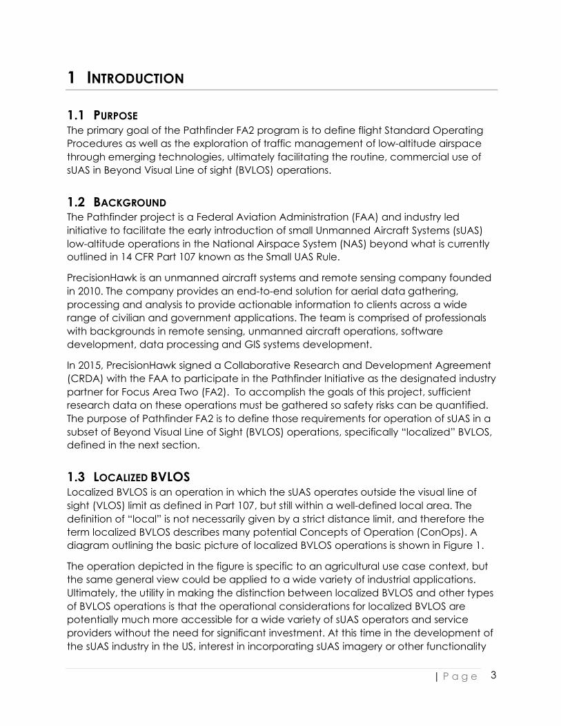
1.3 LOCALIZED BVLOS Localized BVLOS is an operation in which the sUAS operates outside the visual line of sight (VLOS) limit as defined in Part 107, but still within a well-defined local area. The definition of “local” is not necessarily given by a strict distance limit, and therefore the term localized BVLOS describes many potential Concepts of Operation (ConOps). A diagram outlining the basic picture of localized BVLOS operations is shown in Figure 1.
The operation depicted in the figure is specific to an agricultural use case context, but the same general view could be applied to a wide variety of industrial applications. Ultimately, the utility in making the distinction between localized BVLOS and other types of BVLOS operations is that the operational considerations for localized BVLOS are potentially much more accessible for a wide variety of sUAS operators and service providers without the need for significant investment. At this time in the development of the sUAS industry in the US, interest in incorporating sUAS imagery or other functionality
| P a g e
4
into industrial workflows in agriculture, energy, infrastructure, construction, insurance, government and others is high. However, most potential users are unable or unwilling to invest substantial expense in systems which permit very long-range flight (i.e. advanced aircraft, extensive networks of ground based sensor systems) when it is not strictly required for their purposes. Evaluating a localized BVLOS ConOps offers the potential of meeting the business needs of these potential users in the near term while providing valuable data on requirements not filled by these operations to drive further technology and infrastructure development for yet more expanded operations.
Figure 1: Operational view of localized BVLOS operations.
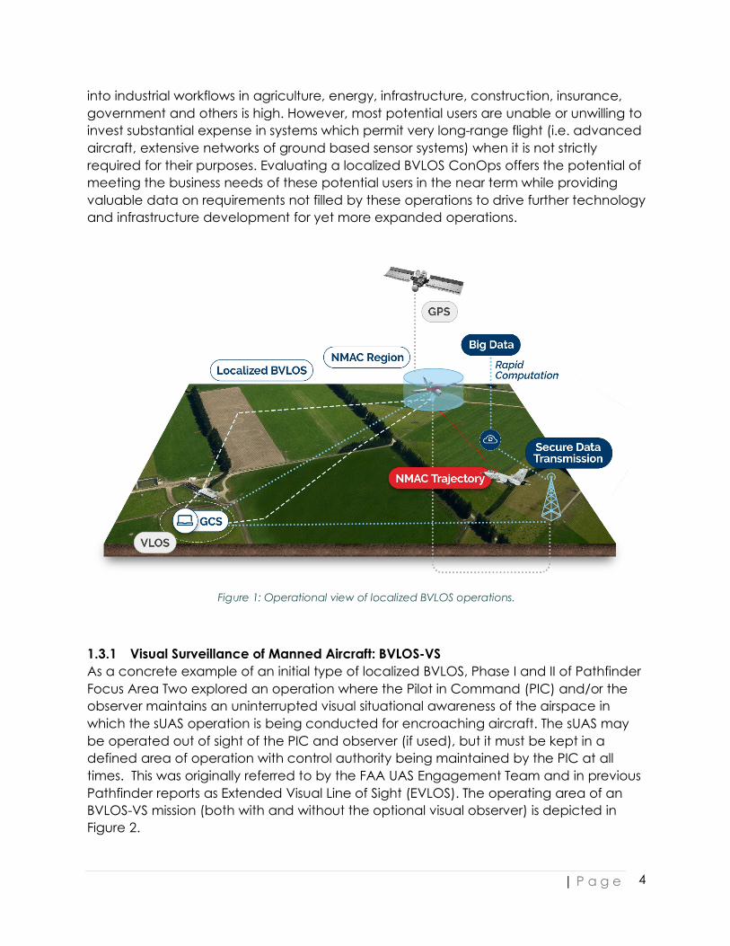
1.3.1 Visual Surveillance of Manned Aircraft: BVLOS-VS As a concrete example of an initial type of localized BVLOS, Phase I and II of Pathfinder Focus Area Two explored an operation where the Pilot in Command (PIC) and/or the observer maintains an uninterrupted visual situational awareness of the airspace in which the sUAS operation is being conducted for encroaching aircraft. The sUAS may be operated out of sight of the PIC and observer (if used), but it must be kept in a defined area of operation with control authority being maintained by the PIC at all times. This was originally referred to by the FAA UAS Engagement Team and in previous Pathfinder reports as Extended Visual Line of Sight (EVLOS). The operating area of an BVLOS-VS mission (both with and without the optional visual observer) is depicted in Figure 2.
| P a g e
5
PrecisionHawk performed experiments exploring this concept between November 2015 and September 2016 (Phase I and II of the CRDA). In August 2016, initial research outcomes from the Pathfinder FA2 effort were used to develop an EVLOS Concept of Operations (ConOps) and operational risk assessment (ORA) resulting in PrecisionHawk being the first commercial sUAS operator to receive a waiver to the visual line of sight requirement of Part 107.
Figure 2:(Left) BVLOS-VS operations without remote visual observer: DEVLOS is the maximum distance at which the PIC can detect a manned intruder. The operating area will be less this distance by a reasonable
buffer. (Right) BVLOS-VS operations with optional remote visual observer to expand operational area.
Primary results indicate that an sUAS Pilot in Command (PIC) will be able to successfully detect and avoid any intruding aircraft 2.37 ± 1.6 NM from the PIC or optional remote visual observer (RVO) provided the following conditions are met:
1. Sun Position: Altitude of sun > 45o above the horizon 2. VFR (Visual Flight Rules) meteorological conditions 3. Visual angle < 5 degrees in quadrant centered on UA location 4. PIC location free of significant noise pollution (i.e. generators, farm equipment,
trucks) 5. PIC qualifications:
a) Meets all Part 107 requirements b) The following additional recommendations for PIC experience and training
were made based on the Phase II research outcomes: i. “Sufficient” VLOS flight time in desired operating environment on the
specific UAS (both aircraft and GCS). This provides the PIC with the ability to selectively “tune out” distractions such as people, equipment or animals. Our recommendation (based on pilot observation) is that 15-20 flight hours in VLOS should be required before BVLOS with visual surveillance of manned aircraft flight should be attempted.
ii. In-field flight training in BVLOS-VS operation from an experienced operator. This is especially important to avoid the PIC focusing exclusively on the specific direction taken by the sUAS as it flies outside the visual line-

| P a g e
6
of-sight or on the Ground Control Station (GCS). Our recommendation (based on pilot observation) is that a single day of training comprised of 2 to 3 short sorties and 2 to 3 longer ones is enough to establish the appropriate strategies necessary for BVLOS-VS flight.
An RVO may be used to permit sUAS flight beyond a distance of DEVLOS from the PIC, we call this “Observer-Augmented BVLOS-VS” operations. This RVO will be stationed at a distance from the PIC to be able to see any traffic that is beyond the range of the PIC’s ability to detect aircraft. This yields a “pill-shaped” operational area (see right-hand image in Figure 2). It is important to note that in these operations, neither the PIC nor the optional RVO are required to maintain line of sight with the sUAS.
While the RVO will not be in direct control of the aircraft, a similar set of requirements as those defined above for PICs is necessary for safe operation. These are:
1. Meets all Part 107 requirements for visual observers 2. Sufficient VLOS observation time in desired operating environment on the
specific UAS (both aircraft and GCS). As above, the recommendation is 15-20 observation hours in VLOS before BVLOS-VS should be attempted.
3. In-field observer training in BVLOS-VS operation from an experienced operator. As above, a single day of training comprised of 2 to 3 short sorties and 2 to 3 longer ones is required. RVOs are not required to operate the sUAS during this training.
The Phase II report presented a substantial analysis of a large number of potential explanatory variables suggested by human factors experts.1 Overall, while some relationships between the metrics measured and the observed variables were evident and provide useful insight as described above, there remained substantial variation in some key metrics unaccounted for by the tested variables. This is not uncommon in human factors studies, but there is a practical consequence in this context. While training and operational constraints such as time of day or location restrictions can help to reduce some of the variation (and should be employed), the BVLOS-VS operation is fundamentally highly variable. The variation observed is the true variation likely to be experienced in the field, making risk-based predictions on how this operation may look when generally deployed difficult. Additionally, from a commercial applicability standpoint, BVLOS-VS operations are limited in scope. An increase from ~ 1 NM to 2-3 NM is an impressively larger amount of area that can be flown from a single location but not yet sufficiently large to accommodate linear flight applications such as power line surveys.
The best possibility for reducing the observed variation and increasing the range lies not in further exhaustive exploration of the factors affecting BVLOS-VS related quantities (if that is even possible) but in employing an assistive technology that removes as much of the field-varying human and environmental dependence as possible. These assistive 1 PrecisionHawk, Pathfinder Focus Area Two Phase II Report, February 2017
| P a g e
7
technologies are available in various stages of development, but with the introduction of technology comes the necessity of assessing new risk modes introduced into the system.
Provided these technologies or combinations thereof can be demonstrated to have acceptable levels of safety, the BVLOS-VS case studied in the previous phase has useful applicability as a potential operational mitigation in the case of assistive technology failure during flight. Despite the observed variation in BVLOS-VS related metrics, participants of all experience levels were generally successful at preventing mid-air collision as defined by the industry-standard term of near mid-air collision (NMAC). The impact of the observed variation on the predictive capability of risk models may only be relevant in the case of general deployment in the NAS, when the number of BVLOS-VS operations could considerably increase. Therefore, Phase III of the Pathfinder FA2 research effort focused on creating and verifying an operational risk assessment (ORA) of the technology-assisted, “localized” BVLOS case.
1.3.2 Technology Assisted Surveillance of Manned Aircraft As a first expansion beyond the BVLOS-VS operations studied in Phase I and II, the present work aims to describe operational requirements for localized BVLOS when conducted in the same low risk environment but beyond the BVLOS-VS limit, with similar requirements on PICs and sUAS. The benefit of the research to potential future states is clear: the basic assistive technologies necessary to facilitate localized BVLOS in low risk environments are likely to be a foundational element of technological solutions in higher-risk scenarios. Understanding the hazards associated with these presently available assistive technologies allows us to define a baseline process from which we can continue to progress and informs a risk-based prioritization of functional development for future technologies.
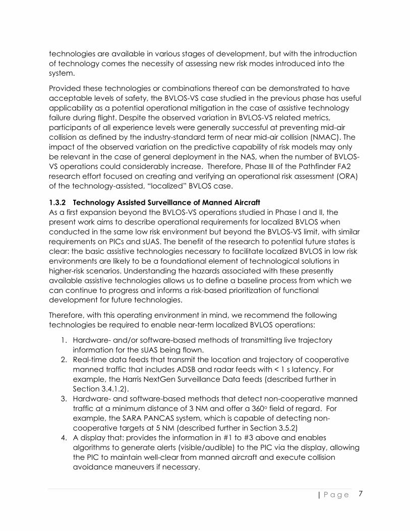
Therefore, with this operating environment in mind, we recommend the following technologies be required to enable near-term localized BVLOS operations:
1. Hardware- and/or software-based methods of transmitting live trajectory information for the sUAS being flown.
2. Real-time data feeds that transmit the location and trajectory of cooperative manned traffic that includes ADSB and radar feeds with < 1 s latency. For example, the Harris NextGen Surveillance Data feeds (described further in Section 3.4.1.2).
3. Hardware- and software-based methods that detect non-cooperative manned traffic at a minimum distance of 3 NM and offer a 360o field of regard. For example, the SARA PANCAS system, which is capable of detecting non-cooperative targets at 5 NM (described further in Section 3.5.2)
4. A display that: provides the information in #1 to #3 above and enables algorithms to generate alerts (visible/audible) to the PIC via the display, allowing the PIC to maintain well-clear from manned aircraft and execute collision avoidance maneuvers if necessary.

| P a g e
8
Certainly, as localized BVLOS operations become more prevalent, and begin to move into more challenging environments (e.g. populated areas, controlled airspace) additional technological support via UTM-like systems and automated onboard detect-and-avoid systems will become necessary to maintain safety. The scope of the present research effort is aimed at developing an understanding of the risks present in early-phase operations and necessary mitigations, with the hope that the outcomes will provide a baseline for understanding risk in more complicated scenarios.
1.3.3 LATAS In keeping with the company’s commitment to airspace safety, PrecisionHawk has developed the LATAS platform, a combined set of geospatial, software, and hardware tools to facilitate safe sUAS operation. Operating over the world-wide cellular networks and satellites, the LATAS platform integrates technologies enabling scalable airspace management to provide necessary services such as sense and avoid, no fly zones, geofencing and aircraft tracking, into a service package for commercial and recreational drone operators. In the future, LATAS may evolve into a system for regulators and air traffic controllers. Engineered with privacy and security protections, LATAS promotes compliance with privacy and data security requirements. A map of the LATAS ecosystem is diagrammed in Figure 3.
Figure 3: LATAS Ecosystem

| P a g e
9
Specifically, LATAS is currently comprised of:
a) Geospatial layers accessible through an API that can be integrated into a drone or ground control station to enhance the situational awareness of the sUAS operator.
a. Airspace Data: Boundaries, Temporary Restrictions, No-Fly Zones b. Traffic Data (Live Feeds): Manned/unmanned aircraft
b) Low-cost cellular-based hardware modules that can be installed on even small UAS without incurring a significant loss of power or adding substantial weight.
a. Modules use GPS to yield accurate positional tracking of sUAS b. sUAS OEMs have the option of incorporating the LATAS module with their
autopilots to enable autonomous response to traffic management system advisories when regulation permits.
The present work was not intended to “test” LATAS specifically, but to use it as a representative assistive technology which incorporates the necessary elements described above. The requirements derived from the resulting research represent a general set of performance-based requirements that can be utilized by other service providers, allowing for flexibility in the specific design of such products.
1.4 PHASE III MISSION STATEMENT As stated in the research plan, the goal of the FA2 Phase III research was to evaluate the impact of assistive technology, such as the LATAS system, on operational risk associated with flight of sUAS in BVLOS applications in the NAS. The key questions that must be asked and quantitatively assessed to generate a thorough operational risk assessment (ORA) are then:
1. What functionality must the assistive technology be capable of to enable safe BVLOS operations in the NAS?
2. How do we expect operators to engage with the assistive technology? 3. In what ways can this human-machine system fail? 4. How do we mitigate the risk of failure?
Quantitative answers to these questions provide regulators with the information they require to define an operational standard for rulemaking.
2 METHODOLOGY AND DATA COLLECTION The Phase III experiments were performed in BVLOS-VS. The measurement plan for quantifying operational risk in early-phase localized BVLOS operations was primarily aimed at assessing failure modes of human-in-the-loop interaction with assistive technologies in the field and associated severity/likelihood levels, and therefore could be executed within the BVLOS-VS framework.

| P a g e
10
2.1 PARTICIPANT POPULATION AND TASK INSTRUCTIONS Participants in the field trials were comprised of 25 volunteers, 16 of which possessed a private pilot’s license or higher in addition to a Part 107 remote pilot’s certificate (the remaining 9 possessed only the Part 107 remote pilot’s certificate). While both manned flight experience and unmanned flight experience differed significantly across the population (and was assessed as an explanatory factor in the analysis in Section 3) on average participants had 10-50 sUAS flight hours (typically on either multirotor or fixed wing systems but not both). Those with manned flight qualifications had on average 50-250 flight hours.
To understand rates and causes of failure in the human-machine system under study, it is important to also define what is meant by task “success”. From an operational risk assessment perspective, we seek to demonstrate that any credible failure possible within the system is either sufficiently mild in severity, sufficiently unlikely to occur or can be successfully mitigated to acceptable severity or likelihood levels. Certainly, this is a crucially important constraint for any operations proposed within the NAS, but it is also important within that context to preserve the original mission of the sUAS whenever possible. This is for commercially important reasons such as ensuring operations can be completed in a timely and efficient manner but may also play a role as sUAS operations move into environments where air traffic density is higher and so automatically moving “out of the way” of a single intruder when such a maneuver is unnecessary may ultimately create other conflicts.
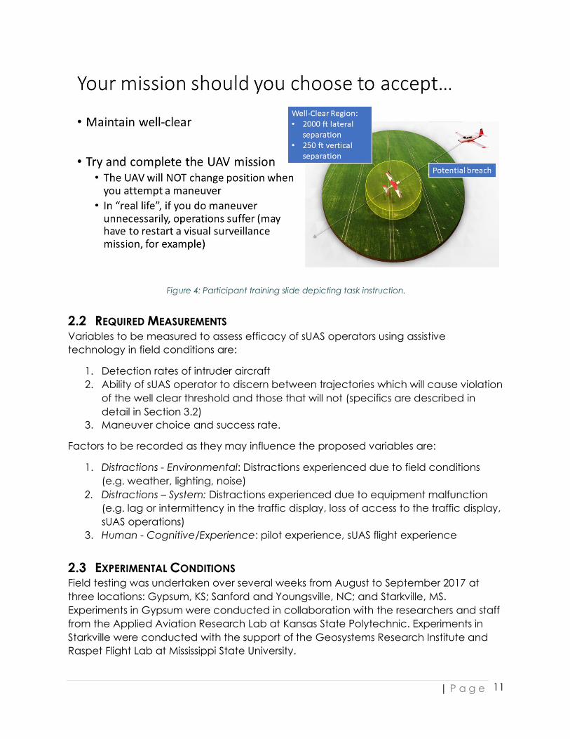
Participants in the experiments were therefore instructed to perform the following task:
1. Maintain well-clear (2000 ft horizontal separation, 250 ft vertical separation). 2. Stay on mission whenever possible.
The training slide describing this task to participants in shown in Figure 4. Note that participants were not provided with any training or suggestions on how to accomplish this, so they were free to make decisions based on their own experience and risk tolerance.
Operator “efficacy” therefore, is defined as the participant’s ability to (a) successfully identify an intruder, (b) correctly identify an intruder trajectory as threshold-violating or non-threshold-violating, (c) choose an appropriate maneuver in the case of a threshold-violating trajectory and (d) effect that maneuver in sufficient time to prevent the breach. The remaining parts of this section describe the required measurements for capturing operator efficacy, the experimental conditions and the test design employed.
| P a g e
11
Figure 4: Participant training slide depicting task instruction.
2.2 REQUIRED MEASUREMENTS Variables to be measured to assess efficacy of sUAS operators using assistive technology in field conditions are:
1. Detection rates of intruder aircraft 2. Ability of sUAS operator to discern between trajectories which will cause violation
of the well clear threshold and those that will not (specifics are described in detail in Section 3.2)
3. Maneuver choice and success rate.
Factors to be recorded as they may influence the proposed variables are:
1. Distractions - Environmental: Distractions experienced due to field conditions (e.g. weather, lighting, noise)
2. Distractions – System: Distractions experienced due to equipment malfunction (e.g. lag or intermittency in the traffic display, loss of access to the traffic display, sUAS operations)
3. Human - Cognitive/Experience: pilot experience, sUAS flight experience
2.3 EXPERIMENTAL CONDITIONS Field testing was undertaken over several weeks from August to September 2017 at three locations: Gypsum, KS; Sanford and Youngsville, NC; and Starkville, MS. Experiments in Gypsum were conducted in collaboration with the researchers and staff from the Applied Aviation Research Lab at Kansas State Polytechnic. Experiments in Starkville were conducted with the support of the Geosystems Research Institute and Raspet Flight Lab at Mississippi State University.
| P a g e
12
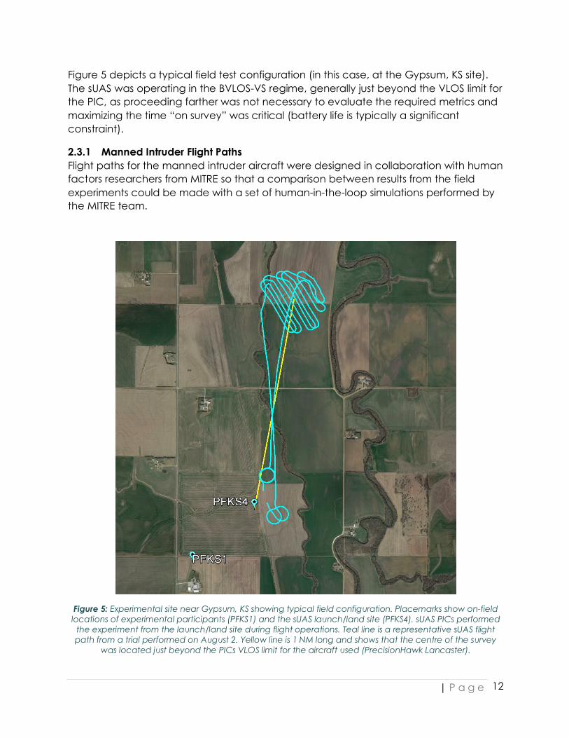
Figure 5 depicts a typical field test configuration (in this case, at the Gypsum, KS site). The sUAS was operating in the BVLOS-VS regime, generally just beyond the VLOS limit for the PIC, as proceeding farther was not necessary to evaluate the required metrics and maximizing the time “on survey” was critical (battery life is typically a significant constraint).
2.3.1 Manned Intruder Flight Paths Flight paths for the manned intruder aircraft were designed in collaboration with human factors researchers from MITRE so that a comparison between results from the field experiments could be made with a set of human-in-the-loop simulations performed by the MITRE team.
Figure 5: Experimental site near Gypsum, KS showing typical field configuration. Placemarks show on-field locations of experimental participants (PFKS1) and the sUAS launch/land site (PFKS4). sUAS PICs performed
the experiment from the launch/land site during flight operations. Teal line is a representative sUAS flight path from a trial performed on August 2. Yellow line is 1 NM long and shows that the centre of the survey
was located just beyond the PICs VLOS limit for the aircraft used (PrecisionHawk Lancaster).
| P a g e
13
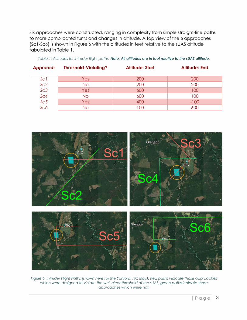
Six approaches were constructed, ranging in complexity from simple straight-line paths to more complicated turns and changes in altitude. A top view of the 6 approaches (Sc1-Sc6) is shown in Figure 6 with the altitudes in feet relative to the sUAS altitude tabulated in Table 1.
Table 1: Altitudes for intruder flight paths. Note: All altitudes are in feet relative to the sUAS altitude.
Approach Threshold-Violating? Altitude: Start Altitude: End
Sc1 Yes 200 200 Sc2 No 200 200 Sc3 Yes 600 100 Sc4 No 600 100 Sc5 Yes 400 -100 Sc6 No 100 600
Figure 6: Intruder Flight Paths (shown here for the Sanford, NC trials). Red paths indicate those approaches
which were designed to violate the well-clear threshold of the sUAS, green paths indicate those approaches which were not.

| P a g e
14
In order to effect the threshold-violating intruder paths (Sc1, Sc3 and Sc5) in the field (and maintain a safe buffer between manned aircraft and sUAS generally) the intruder was equipped with a LATAS tag that had been modified to report its GPS altitude as half the actual altitude. This allowed the intruder to enter with a safe vertical separation from the sUAS at all times. It was therefore also crucial to minimize any visual contact between the experimental participants and the intruder aircraft during the decision-making process to avoid confusion between what the traffic display was recording and any direct observation of the intruder. Participants were asked to note on their questionnaires during and after the test if this type of discrepancy did occur.
Additionally, due to the uncertainty in the actual timing of the flight path of the sUAS at the time of intruder approach, not all paths which were intended to be threshold-violating ultimately resulted in a threshold violation (we did successfully miss the sUAS when we intended to do so)2. In the subsequent analysis in Section 3, all approaches were evaluated for threshold violation regardless of their intended design.
2.3.2 Baseline and Enhanced Traffic Displays During a given field trial, participants are asked to use the LATAS display to aid in their decision-making process. The set of elements shown on that display for a given approach fall into two categories: the baseline display representing the available display elements within LATAS at the time of the experiment and an enhanced display with a series of additional warnings. The baseline display is pictured in Figure 7.
Figure 7: Baseline Display elements. In this example, the fixed wing icon is the sUAS (ownship). The intruder is displayed with the multirotor icon because it is reporting position through a standard LATAS tag. Inset shows
information available when a visible icon is clicked.
2 Thus, leading us to the anecdotal but nonetheless interesting conclusion that it turns out to be much harder than expected to create well-clear violations with sUAS in realistic scenarios, even when you plan to aim your manned aircraft right at them.

| P a g e
15
The additional elements available when the enhanced display was activated are shown in Figure 8. These elements were developed for the above-mentioned human-in-the-loop simulations performed at MITRE and include:
1. A white circle indicating the well clear zone of 2000 ft radius around the ownship icon appears upon activation of the elements.
2. A vertical “band” display on the right-hand side of the screen with scale from 0-400’ AGL (Above Ground Level). Ownship altitude is shown as a blue dot on this scale.
3. Other aircraft are depicted with a continuously-updating relative altitude (in feet) and lateral distance (in NM) in numbers under the aircraft icon.
4. If another aircraft is within 3 NM of ownship, the intruder aircraft icon is highlighted amber.
5. Vertical and lateral avoidance bands, based on DO-365, are added into the vertical band display and the well clear zone circle respectively. Those altitudes and directions colored amber indicate maneuvers that could lead to well clear violation based on current flight trajectories, and are updated continuously.
Figure 8: Additional elements shown in the enhanced display.
2.4 FIELD TEST DESIGN As in the design of Phase II, the Phase III field tests were structured such that the sUAS is flying at a pre-determined location beyond the participant’s line of sight, but within the BVLOS-VS limit. A manned intruder aircraft was introduced from a direction unknown to the participant, and flying a trajectory not pre-disclosed to the participant, representing actual conditions that may be experienced during operation.
Trajectories for the sUAS were extracted from the telemetry logs of the sUAS post-flight. The Intruder was equipped with both an aviation-rated Garmin GPS unit from which the
| P a g e
16
trajectory files were extracted at the conclusion of the sortie as well as a LATAS tag which served to transmit the intruder position in real-time to the LATAS system.
In some scenarios, cellular signal at the manned aircraft altitudes was not available, so the intruder position was produced by the LATAS trajectory simulation function. The actual manned intruder aircraft flew the planned flights even during the simulation and participants were not made aware that the intruder positional information they were receiving was simulated. While coordination was generally good (and much of the approach occurred beyond the limit of the participant’s ability to accurately determine the trajectory of the manned aircraft, although they could tell it was “up there somewhere”) in some cases a situation occurred where the manned aircraft got noticeably ahead of the simulated path. While this was obviously not planned, it did provide an opportunity to observe qualitatively how participants reacted to discrepancies between the display and their visual observations. This is discussed in more detail in Section 3.2.
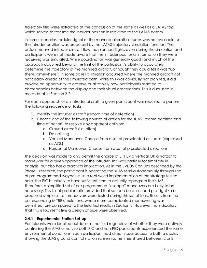
For each approach of an intruder aircraft, a given participant was required to perform the following sequence of tasks:
1. Identify the intruder aircraft (record time of detection) 2. Choose one of the following courses of action for the sUAS (record decision and
time of action) to resolve any apparent collision: a. Ground aircraft (i.e. ditch) b. Do nothing c. Vertical Maneuver: Choose from a set of preselected altitudes (expressed
as AGL). d. Horizontal Maneuver: Choose from a set of preselected directions.
The decision was made to only permit the choice of EITHER a vertical OR a horizontal maneuver for a given approach of the intruder. This was partially for simplicity in analysis, but also has a practical implication. As in the EVLOS ConOps described by the Phase II research, the participant is operating the sUAS semi-autonomously through use of pre-programmed waypoints. In a real-world implementation of the strategy tested here, the PIC is unlikely to have sufficient time to actually reprogram the sUAS. Therefore, a simplified set of pre-programmed “escape” maneuvers are likely to be necessary. This is not problematic provided that set can be described pre-flight so a proposed simple set of maneuvers were tested during this set of trials. Results from the corresponding MITRE simulations, where more complicated maneuvering was permitted, are compared to the field trial results in Section 3. However, no indicators that this is too restrictive a design choice were observed.
2.4.1 Experimental Station Set-up Participants were located outdoors in the field regardless of whether they were actively controlling the sUAS or not, so both PIC and non-PIC participants experienced the same environmental conditions. Each participant had direct visual access to both a display showing the sUAS ground control station screen (sometimes shared between 2 or 3
| P a g e
17
participants at the same table, but always in direct line of sight) and a personal tablet or laptop with the LATAS display. PICs always had direct access to the ground control station during the experiment. All other participants received a simultaneous broadcast of that screen over TeamViewer webcasting software.
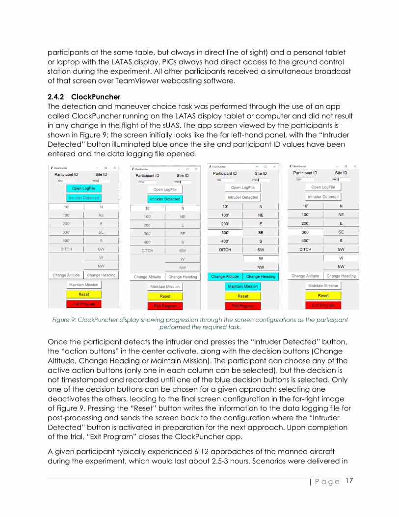
2.4.2 ClockPuncher The detection and maneuver choice task was performed through the use of an app called ClockPuncher running on the LATAS display tablet or computer and did not result in any change in the flight of the sUAS. The app screen viewed by the participants is shown in Figure 9; the screen initially looks like the far left-hand panel, with the “Intruder Detected” button illuminated blue once the site and participant ID values have been entered and the data logging file opened.
Figure 9: ClockPuncher display showing progression through the screen configurations as the participant
performed the required task.
Once the participant detects the intruder and presses the “Intruder Detected” button, the “action buttons” in the center activate, along with the decision buttons (Change Altitude, Change Heading or Maintain Mission). The participant can choose any of the active action buttons (only one in each column can be selected), but the decision is not timestamped and recorded until one of the blue decision buttons is selected. Only one of the decision buttons can be chosen for a given approach; selecting one deactivates the others, leading to the final screen configuration in the far-right image of Figure 9. Pressing the “Reset” button writes the information to the data logging file for post-processing and sends the screen back to the configuration where the “Intruder Detected” button is activated in preparation for the next approach. Upon completion of the trial, “Exit Program” closes the ClockPuncher app.
A given participant typically experienced 6-12 approaches of the manned aircraft during the experiment, which would last about 2.5-3 hours. Scenarios were delivered in

| P a g e
18
random order to avoid prediction by the participants. Participants would use the baseline display for the first half of the experiment and the enhanced display for the second half. A sample distribution of scenarios and display types for 12 approaches is shown in Figure 10.
Figure 10: Sample trial card for 12 approaches.
Combining the Intruder and sUAS trajectories with the ClockPuncher output yields the measurements required for assessment of participant efficacy described in Section 2.2. Proposed factors influencing that efficacy, including distractions, were collected via questionnaires administered before, during and after the field test. These questionnaires are described in the next section.
2.5 PARTICIPANT QUESTIONNAIRES Prior to the field test, during the sign-up process, participants were asked to indicate their level of pilot training and experience (both manned and unmanned). A representative questionnaire of this type (in this case, for the Gypsum, KS experiments performed with the Kansas State Polytechnic AARC) is available in Appendix A.
On the day of the experiment, aside from the field test itself, participants had a pre-evaluation session consisting of a series of survey questions about factors that may affect their detection and decision-making process (i.e. fatigue). A brief training session to familiarize them with the test software (ground control station and LATAS displays, as well as the ClockPuncher app) and field environment also occurred at this time. During the training session, the different collision avoidance choices were described. Participants were instructed on the concept of well-clear violation (WCV) as the threshold-violating “event” they were aiming to prevent. The training session was kept short on purpose as the experiment was designed to assess both experts and non-experts at their current level of skill, so an effort was made in particular not to introduce “new” strategies to participants with limited field experience.
| P a g e
19
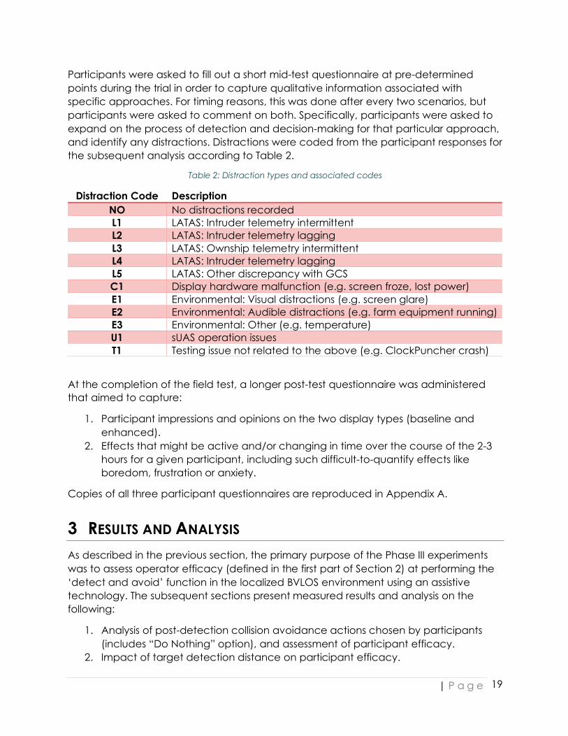
Participants were asked to fill out a short mid-test questionnaire at pre-determined points during the trial in order to capture qualitative information associated with specific approaches. For timing reasons, this was done after every two scenarios, but participants were asked to comment on both. Specifically, participants were asked to expand on the process of detection and decision-making for that particular approach, and identify any distractions. Distractions were coded from the participant responses for the subsequent analysis according to Table 2.
Table 2: Distraction types and associated codes
Distraction Code Description NO No distractions recorded L1 LATAS: Intruder telemetry intermittent L2 LATAS: Intruder telemetry lagging L3 LATAS: Ownship telemetry intermittent L4 LATAS: Intruder telemetry lagging L5 LATAS: Other discrepancy with GCS C1 Display hardware malfunction (e.g. screen froze, lost power) E1 Environmental: Visual distractions (e.g. screen glare) E2 Environmental: Audible distractions (e.g. farm equipment running) E3 Environmental: Other (e.g. temperature) U1 sUAS operation issues T1 Testing issue not related to the above (e.g. ClockPuncher crash)
At the completion of the field test, a longer post-test questionnaire was administered that aimed to capture:
1. Participant impressions and opinions on the two display types (baseline and enhanced).
2. Effects that might be active and/or changing in time over the course of the 2-3 hours for a given participant, including such difficult-to-quantify effects like boredom, frustration or anxiety.
Copies of all three participant questionnaires are reproduced in Appendix A.
3 RESULTS AND ANALYSIS As described in the previous section, the primary purpose of the Phase III experiments was to assess operator efficacy (defined in the first part of Section 2) at performing the ‘detect and avoid’ function in the localized BVLOS environment using an assistive technology. The subsequent sections present measured results and analysis on the following:
1. Analysis of post-detection collision avoidance actions chosen by participants (includes “Do Nothing” option), and assessment of participant efficacy.
2. Impact of target detection distance on participant efficacy.

| P a g e
20
3. Discussion of predicted participant efficacy for cooperative and non-cooperative targets.
4. Participant Response to Display Elements: Beyond the quantitative assessment of efficacy.
For any given approach of the Intruder, possible outcomes to the detect-and-avoid process are as follows:
1. Non-Detect: Participant fails to detect the Intruder prior to the occurrence of threshold violation.
2. Pre-Action or After-The-Fact: Participant successfully detects the Intruder prior to a threshold violation, but is unable to choose a maneuver prior to the violation.
3. Participant successfully detects Intruder, and correctly determines it is on a collisional course. At this point:
a. Participant chooses a collision avoidance action prior to violation, but due to either maneuver choice or sUAS dynamics it does not prevent threshold violation.
b. Participant makes a timely and effective choice of collision avoidance action, thus preventing threshold violation.
4. Participant successfully detects Intruder on collisional course, but chooses to do nothing (i.e. does not successfully recognize the Intruder as a threat).
5. Participant successfully detects Intruder, and chooses a collision avoidance action that is unnecessary (i.e. threshold violation would not have occurred if no action was chosen).
6. Participant successfully detects Intruder, assesses correctly that it is not on a collisional trajectory with the sUAS and chooses to take no action.
“Mid-air collision” in the subsequent sections is defined using the industry-standard term of near mid-air collision (NMAC). The NMAC region around the Intruder is commonly defined as a cylinder 500 ft in radius (rNMAC) and 200 ft in height (hNMAC) centered on the Intruder.
“Well-clear violation” indicates that the sUAS came within the proposed well-clear region of rWCV = 2000 ft and hWCV = 500 ft (centered on the intruder). As the task given to the participants was to “remain well-clear” according to this definition, the following analysis focusses primarily on well-clear violation (WCV). The single NMAC that was observed in the present sample of observations is discussed in the section on the impact of equipment failure (Section 3.4.1.1).
3.1 NON-DETECT AND PRE-ACTION In all cases, the participant successfully detected the intruder on-screen prior to any well-clear violation. For Pre-Action events, as described above, a single WCV event was recorded.

| P a g e
21
Statistical analysis of a single event for explanatory factors is not possible, but examination of the participant questionnaire responses for this event is qualitatively informative:
Table 3: Participant questionnaire response for pre-action well-clear violation event
Question Response Approach A2 (Scenario 4) Display Type Tablet Visual Aids Engaged? No sUAS Type Fixed Wing Do you have a current Aviation Medical? Class 3 Medical Do you have a current Pilot's License? Yes, I have a private pilot certificate Do you have a current Instructor Certificate?
No, I do not possess an Instructor Certificate.
How many manned flight hours do you currently have?
50 - 250 hours
How many unmanned flight hours do you currently have with multi-rotor systems?
100+ sUAS flight hours
How many unmanned flight hours do you currently have with fixed-wing systems?
10-50 sUAS flight hours
How did the decision-making process occur?
I envisioned the "hockey puck" volume around the sUAS. If the manned aircraft came close to violating that volume, I would first adjust my altitude to avoid a conflict, then my heading if needed.
Did you experience any distractions during the test?
No
Are there any other observations you would like to share?
The manned aircraft in a dive nearly threw me for a loop--I had to keep clicking quickly back and forth between the aircraft to monitor their altitudes.
As can be seen in Table 3, this was the participant’s second approach of the experiment (A2) and the first where a sharp turn by the intruder into the operational area of the sUAS was observed (Scenario 4). The participant indicates they were surprised by the sudden flight path change of the intruder, and this is likely the primary cause of the pre-action violation. The participant detected the manned intruder at a horizontal separation of ~ 3 NM from the sUAS indicating this was not a detection failure (recall experimental conditions had the zoom level of the screen set such that the maximum extent was just over 3 NM from the sUAS). On subsequent approaches with similar turns (Scenarios 3, 5, 6) no further pre-action violations occurred with this participant.

| P a g e
22
3.1.1 Risk Mitigation: In-Field or Simulation-based Training This example illustrates the importance of training that involves some interaction of the participant with a set of representative intruder trajectories, either in-field with real equipment or using a simulated environment. While this was the only pre-action violation observed in the sample, the “surprise” experienced by the participant could be (and was, based on the rest of this participant’s results) successfully mitigated by exposure to a variety of trajectories.
3.2 SIGNAL DETECTION THEORY ANALYSIS To evaluate the process of collision avoidance for the remaining four outcomes in the list given above, signal detection theory (SDT), a standard technique in human-factors research is used. Specifically, SDT is a commonly used model of the decision-making process for experimental participants who need to decide between different classes of items (in this case, whether a collision avoidance action is required) and to assess any bias in the participant population to favor a particular type of response.
Specifically, the underlying premise is that for a given participant, both signal and noise are represented probabilistically and how much these representations overlap can be estimated just by looking at the participant’s responses and comparing them to if the signal (in this case, a threshold-violating trajectory) was actually present. The participant will base their decision on a unique internal criterion called β, where signal will be reported present when the internal signal is stronger than β and absent when the internal signal is weaker than β. Therefore a “Hit” in this context, is somewhat counterintuitively defined as both types of Outcome 3 in the list above (i.e. successful identification of collisional trajectory). Likewise, a “Miss” is as described in Outcome 4, false alarms in Outcome 5 and correct rejection (CR) in Outcome 6. To be more specific in the definitions:
Collisional Trajectory Not Collisional Trajectory Action Chosen ≠ Do Nothing Hit False Alarm Action Chosen = Do Nothing Miss Correct Rejection
All response probabilities are reflected as a part of the area underneath a normal curve. If the probability of each response type is therefore known, both the signal and the noise distributions can be estimated based on simple statistical principles. Specifically, determining the z-score (i.e., the standard deviation) of the probabilities associated with each distribution will provide an estimate of the properties of the underlying distributions. The z-value associated with the probability of a hit (Phit) will reflect where β is positioned relative to the signal distribution. Similarly, the z-value associated with the probability of a false alarm (PFA) will reflect the position of β relative to the noise distribution.
| P a g e
23
From these z-scores two key statistics can be computed:
1. Sensitivity index d’: 𝑑" = 𝑍(𝑃'()) − 𝑍(𝑃,-) Conceptually, sensitivity refers to how hard or easy it is to detect that a target stimulus is present from background events and is calculated from the difference of the z-scores for Phit and PFA (i.e. how far apart are the signal and noise distributions?) d’ is independent of the location of β, and is therefore a measure of performance that is independent of individual participant bias.
2. Response Bias C: 𝐶 =− (𝑍(𝑃'()) + 𝑍(𝑃,-)) 2⁄ Bias is the extent to which one response is more probable than another. That is, a receiver may be more likely to respond that a stimulus is present or more likely to respond that a stimulus is not present. It is estimated as the difference between the placement of β by actual participant and the placement of β by an “unbiased: observer (i.e., an ideal observer) who would demonstrate equal proportions of misses and false alarms. Bias is independent of sensitivity.
This approach was successfully used to model the collision avoidance process in a recent evaluation of visual observer performance during nighttime VLOS operations.3 A more comprehensive explanation of SDT can be found in Stanislaw and Todorov (1999)4.
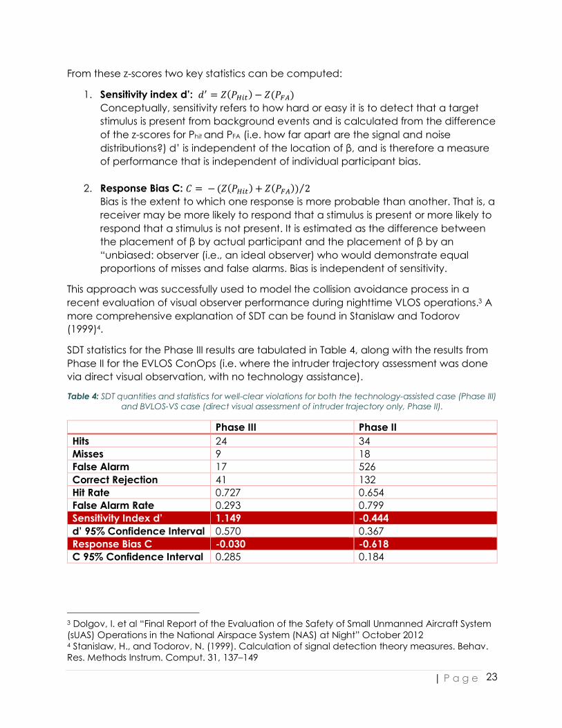
SDT statistics for the Phase III results are tabulated in Table 4, along with the results from Phase II for the EVLOS ConOps (i.e. where the intruder trajectory assessment was done via direct visual observation, with no technology assistance).
Table 4: SDT quantities and statistics for well-clear violations for both the technology-assisted case (Phase III) and BVLOS-VS case (direct visual assessment of intruder trajectory only, Phase II).
Phase III Phase II Hits 24 34 Misses 9 18 False Alarm 17 526 Correct Rejection 41 132 Hit Rate 0.727 0.654 False Alarm Rate 0.293 0.799 Sensitivity Index d’ 1.149 -0.444 d’ 95% Confidence Interval 0.570 0.367 Response Bias C -0.030 -0.618 C 95% Confidence Interval 0.285 0.184
3 Dolgov, I. et al “Final Report of the Evaluation of the Safety of Small Unmanned Aircraft System (sUAS) Operations in the National Airspace System (NAS) at Night” October 2012 4 Stanislaw, H., and Todorov, N. (1999). Calculation of signal detection theory measures. Behav. Res. Methods Instrum. Comput. 31, 137–149

| P a g e
24
As a side note, for both Phase II and Phase III flight planning was done using an “average” predicted position of the sUAS to try and obtain a sufficient number of trajectories that would appear “collisional” to the participants in the field. The planned number was about half of all approaches for both years. Despite the fact that the sUAS remained relatively close to this average position while still flying a typical survey pattern, final sample sizes were well short of this proportion. Therefore, the full sample is pooled to evaluate the SDT statistics and 95% confidence intervals are provided to make the comparison.
Comparison of pooled sensitivity indices d’ for both phases shows significantly better performance for the Phase III technology assisted case, as might be predicted (i.e. participants found it easier to detect a “threat” using the Phase III technology) Specifically, a negative d’ in the BVLOS-VS case was reflective of the high false alarm rate; participants would generally choose to change trajectory to avoid incoming aircraft whether they needed to or not. While this kept the operation clear of mid-air collisions, it creates problems in commercial applications that have potentially short operational windows. Additionally, frequent and unnecessary “emergency” maneuvering may become more difficult as operations progress to areas with a more significant density of air traffic, ground based infrastructure, or complex terrain. Pooled response biases for both populations are positive indicating a conservative bias (i.e. a tendency towards false alarm). Note, however, the 95% confidence interval for C in the technology assisted case does overlap the “unbiased” case of C = 0, so we can’t say with statistical confidence that bias exists in the technology-assisted case.
While unfortunately there is not sufficient sample sizes to compare d’ and C for individual participants, it is possible to divide the observations into those using the baseline display and those where the visual aids were engaged. This yields an interesting comparison as shown in Table 5. While the 95% confidence intervals for both d’ and C overlap, this is not necessarily an indicator of the lack of statistical significance to the difference, particularly for d’. Certainly, the raw numbers indicate that use of the display improved threat detection.
Table 5: SDT quantities and statistics for well-clear violations for the technology-assisted case with either the baseline display only or visual aids engaged.
LATAS: Baseline LATAS: Enhanced Hits 9 15 Misses 8 1 False Alarm 10 7 Correct Rejection 23 18 Hit Rate 0.529 0.937 False Alarm Rate 0.303 0.280 Sensitivity Index d’ 0.589 2.116 d’ 95% Confidence Interval 0.746 1.097 Response Bias C 0.221 -0.475 C 95% Confidence Interval 0.373 0.549

| P a g e
25
3.2.1 Simulation Results Results from the MITRE simulations provide additional clarity. SDT statistics are computed for the display configurations within the simulation that approximately corresponded to the baseline and enhanced display configurations used in the field. Simulation baseline and enhanced display elements are pictured in Figure 11.
Figure 11: Simulation baseline (left) and enhanced "Bands" display. Images provided by MITRE.
There are some key differences that contribute to the final comparison:
1. The primary difference was in the baseline configuration: the simulated baseline configuration already included the well-clear circle as well as the relative altitude/distance numbers and amber highlight on the intruder icon.
2. Experiment design within the simulation was fully randomized, so the baseline display configuration wasn’t necessarily the first configuration presented to participants as in the field trials.
3. Simulation participants had a “practice run” for each new display configuration, so learning effects are likely to be minimized in the simulation results.
4. Effects due to lag, intermittency or other display issues would not be present in the simulation.
Table 6: SDT quantities and statistics for simulation results. Statistics provided by MITRE.
Simulation: Baseline Simulation: Enhanced (Bands) Hits 85 90 Misses 5 0 False Alarm 22 21 Correct Rejection 23 24 Hit Rate 0.944 0.994 False Alarm Rate 0.489 0.467

| P a g e
26
Sensitivity Index d’ 1.621 2.623 d’ 95% Confidence Interval 0.559 1.034 Response Bias C -0.783 -1.228 C 95% Confidence Interval 0.279 0.517
For ease of comparison, sensitivity indices and response bias for all available display configurations (as well as the pooled Phase II BVLOS-VS results) are plotted with their 95% confidence intervals in Figure 12 and Figure 13 respectively. The horizontal axis categories were placed in order of increasing “information” on both graphs (although the enhanced displays used via LATAS in-field and the simulation version contained effectively the same elements).
The observed trend in Figure 12 is compelling, despite overlap in the confidence intervals from category to category. Of particular interest is the increase in sensitivity observed in the simulation baseline configuration over the in-field baseline, where no direct “assistance” in the form of blocked headings or altitudes was offered. In the simulation baseline, participants were able to see in particular the relative altitude and distance of the intruder at a glance, whereas they would have needed to click the intruder icon in the baseline display. The well-clear circle also would have been available in the simulation baseline, potentially helping participants to judge lateral distances more effectively without having to interpret the numbers against the existing map scale.
Some interesting features in the response bias are also visible in Figure 13. Recall that C=0 implies no bias in response criterion, and negative values of C indicate a conservative bias (false positives more likely than misses). Both of the in-field configurations overlap with zero, which could potentially be the result of the smaller sample size but could also reflect that in-field participants were operating under the “dual constraint” task depicted in Figure 4. Discussion with the MITRE team indicated that the “maneuver only if you need to” constraint was possibly not as strongly made in the simulation training (but it was definitely part of the instruction set).
In either case, when answering the question of whether the visual aids in the enhanced display have a substantial impact of the safety of the operation, of particular interest are those approaches which resulted in well-clear violations due to either Misses or “Late Actions” (Outcome 3a). Therefore, the subsequent analysis examines additional collected data on these categories in an effort to clarify the potential differences between the two types of displays.

| P a g e
27
Figure 12: Sensitivity index d' with 95% confidence interval bars shown for Phase II results, baseline displays
(in-field/LATAS and simulation) and enhanced displays (in-field/LATAS and simulation)
Figure 13: Response Bias C with 95% confidence interval bars shown for Phase II results, baseline displays (in-
field/LATAS and simulation) and enhanced displays (in-field/LATAS and simulation). Amber horizontal line shows the zero-bias location.

| P a g e
28
3.3 FAILURE TO IDENTIFY TRAJECTORY LEADING TO WELL-CLEAR VIOLATION (MISS) As tabulated above for the in-field data, 9 total approaches led to a miss condition. Details of these 9 approaches are shown below in Table 7. Note that all reported horizontal and vertical separations are in meters (for reference, 2000 ft ~ 610 m, 250 ft ~ 76 m)
Table 7: Miss observations. All distances reported in meters.
From the table, it is clear that detection of the target and therefore sufficient time to respond to the potential threat are not the primary cause of the miss. Horizontal separation of the sUAS and intruder is well above the well-clear threshold, and response times are often > 90 s which is ample time for decision-making. Distractions may play some role, but many of the associated questionnaire responses indicate distractions were not a factor. One additional complication in interpretation is that in the present experimental design the approaches using the baseline display were always performed first, so the “surprise” factor discussed above in Section 3.1 may also play a role.
We can also examine further by reviewing participant responses to the mid-test survey question “How did the decision-making process occur?”. These are given in Table 8.
Table 8: Participant decision-making descriptions for Miss encounters. AOI is Area of Interest.
PartID Approach How did the decision-making process occur? 4252 A well on first vertical seperation was there - second there was a lag on screen
and both disapeared - 4252 B vertical seperation 4536 A by watching the screen and not getting a warning 4536 B while waiting to see which direction the aircraft was going to go 7564 B Visual clues from GCS and Latas. ClockPunch left visible on screen may have
delayed intruder detect. Forgot I was able to click on intruder for altitude information which may have changed decision making on earlier approaches.

| P a g e
29
8303 B I estimated the approach angle of the manned aircraft and subtracted the altitudes
9802 A Saw aggressor begin to pass AOI as drone headed back away from aggressor. then aggressor turned toward drone. Would have authored further control input if able (avoid/evade)
A common theme is misinterpretation or incorrect use of the available display elements, for the vertical scale in particular (see responses for participants 4252, 7564 and 8303). Participant 9802 does cite the “surprise” factor of the intruder turning into the operational area on Scenario 4 and indicates that they would have made further collision avoidance decisions if permitted by the experimental setup. As the “no maneuver” decision was made while the sUAS and intruder were still well outside the horizontal well-clear threshold at the time the action was chosen (Hsep = 910.4 m), the participant would have likely had time to execute an appropriate avoidance maneuver. Participant 4536 indicates that for Approach A they were waiting to receive a warning, despite being on the baseline display where no warnings were present.
These responses, and a comparison to the respectively minimal number of misses observed in the simulation (Table 6) indicate an opportunity to mitigate the risk of a Miss encounter via some simple display element design considerations, and sufficient training on the display prior to field operations. This is discussed in more detail in the next section.
3.3.1 Risk Mitigation: Display Elements Design and Display System Training As described in Section 2.3.2, the baseline display had a basic set of alerts and options for getting information to the participant about the manned intruder. Specifically, the altitude and heading of the intruder could be obtained by “clicking” with the mouse on the intruder icon on-screen. This yields a snapshot of the current information and does not update in real-time. While this was described in the brief training session given before the experiment, participants had difficulty remembering that:
a) They could click on the intruder icon to get more information b) Once clicked, the displayed information would remain present onscreen and not
continually update, even though the intruder icon was moving.
The relative altitude and separation numbers added to the intruder icon in the enhanced visual aid display successfully deal with both of these issues, and were largely preferred by the participants as shown in Figure 14. This result was also evident in the questionnaires administered post-simulation.

| P a g e
30
Figure 14: Participant responses on questions related to the relative altitude and distance indicators
available in the enhanced display.
Training, as described above in Section 3.1.1, will also help to remove those issues occurring because of simple inexperience. In the post-test survey, participants were also asked to comment on whether or not their decision-making process improved over time and just over half (15 out of 26 submitted surveys) indicated an improvement either due to the visual aids or just additional experience with the display. All 5 of the participants who experienced a Miss indicated they believe their decision-making process improved, their comments are given below in Table 9.
Table 9: Change in decision-making process over time (Participant Post-Test Survey responses)
PartID Did the decision-making process change during the duration of the test? Did you feel that you improved over time, stayed the same or got worse?
4252 Got better after leaning system 4536 improved over time 7564 Improved 8303 Yes the decision process improved after the introduction of on-screen monitoring aids and the
experience of using the aids helped to improve use of them afterward 9802 Utilizing the improved display
3.4 COLLISION AVOIDANCE MANEUVER SUCCESS RATE (HITS VS. LATE-ACTION) The final part of the collision avoidance assessment is further evaluation of the “Hit” observations above: recall that in the original list of potential outcomes a Hit was given

| P a g e
31
as a successful identification of a threshold-violation trajectory prior to any violation. However, there are two outcomes to the identification of a threshold-violation trajectory related to the timing of the chosen action; in a Hit, the participant will choose to maneuver but will they do so in time to prevent a subsequent well-clear violation?
Late-Action details are tabulated below in Table 10. As for the Miss encounters described in Section 3.3, Late-Action does not appear to result from a difficulty to detect the aircraft; horizontal separations are much greater than the well-clear threshold at the time of detection and the mean response time is ~ 58 s (shortest observed in below table is still a relatively leisurely 23 s). Unlike the Miss encounters, the presence of the enhanced visual aids does not appear to significantly influence the rate of late-action.
Table 10: Late Action Observations. All distances reported in meters.
Two explanatory factors from the above table are of note. One, while the rate of distractions experienced in Late-Action encounters does not differ much from Miss encounters, distractions experienced in the Late-Action encounters were relatively more serious issues related to equipment malfunction or imprecise telemetry. Suggested mitigations for these potential problems are outlined in the next section.
Secondly, all of the Late-Action cases occurred during an experiment where the sUAS was of the fixed-wing type. A review of the cases where participants in the above table cited no distractions reveals that in all cases the participants chose a vertical maneuver. This is not, in and of itself, incorrect; vertical maneuvering even with a fixed-wing aircraft (the ‘Descend and Loiter’ option in particular) in the BVLOS-VS case was very successful but only because participants would choose to do so almost immediately upon detection of the intruder. It is often difficult to resolve potential threshold violations using late-stage vertical maneuvering with a fixed-wing aircraft, a
| P a g e
32
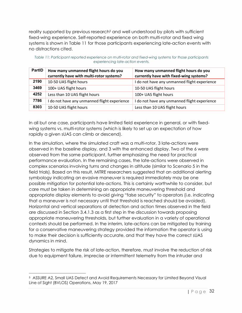
reality supported by previous research5 and well understood by pilots with sufficient fixed-wing experience. Self-reported experience on both multi-rotor and fixed wing systems is shown in Table 11 for those participants experiencing late-action events with no distractions cited.
Table 11: Participant reported experience on multi-rotor and fixed-wing systems for those participants experiencing late-action events.
PartID How many unmanned flight hours do you currently have with multi-rotor systems?
How many unmanned flight hours do you currently have with fixed-wing systems?
2190 10-50 UAS flight hours I do not have any unmanned flight experience 3469 100+ UAS flight hours 10-50 UAS flight hours 4252 Less than 10 UAS flight hours 100+ UAS flight hours 7786 I do not have any unmanned flight experience I do not have any unmanned flight experience 8303 10-50 UAS flight hours Less than 10 UAS flight hours
In all but one case, participants have limited field experience in general, or with fixed-wing systems vs. multi-rotor systems (which is likely to set up an expectation of how rapidly a given sUAS can climb or descend).
In the simulation, where the simulated craft was a multi-rotor, 3 late-actions were observed in the baseline display, and 3 with the enhanced display. Two of the 6 were observed from the same participant, further emphasizing the need for practical performance evaluation. In the remaining cases, the late-actions were observed in complex scenarios involving turns and changes in altitude (similar to Scenario 5 in the field trials). Based on this result, MITRE researchers suggested that an additional alerting symbology indicating an evasive maneuver is required immediately may be one possible mitigation for potential late-actions. This is certainly worthwhile to consider, but care must be taken in determining an appropriate maneuvering threshold and appropriate display elements to avoid giving “false security” to operators (i.e. indicating that a maneuver is not necessary until that threshold is reached should be avoided). Horizontal and vertical separations at detection and action times observed in the field are discussed in Section 3.4.1.3 as a first step in the discussion towards proposing appropriate maneuvering thresholds, but further evaluation in a variety of operational contexts should be performed. In the interim, late-actions can be mitigated by training for a conservative maneuvering strategy provided the information the operator is using to make their decision is sufficiently accurate, and that they have the correct sUAS dynamics in mind.
Strategies to mitigate the risk of late-action, therefore, must involve the reduction of risk due to equipment failure, imprecise or intermittent telemetry from the intruder and
5 ASSURE A2, Small UAS Detect and Avoid Requirements Necessary for Limited Beyond Visual Line of Sight (BVLOS) Operations, May 19, 2017

| P a g e
33
sufficient in-field experience on the sUAS intended for use in the final operation. These are discussed in more detail in the next section.
3.4.1 Risk Mitigation: Equipment Failure, Telemetry Assurance and Flight Experience
3.4.1.1 Equipment Failure Appropriate mitigations for display hardware failure typically involve bringing backup display equipment and power sources to the field. Should the LATAS display become completely unavailable, these mitigations can certainly be performed, but there will be a loss of the awareness provided by the LATAS display during the replacement time. Therefore, operations become limited to any information provided by the remaining aircraft detection tools (e.g. onboard or ground-based detection systems not communicating through LATAS) and actions taken by the operator must reflect this new operational condition. This is discussed in some detail for the case of an onboard detection system in Section 3.5.2.
Note that the single NMAC observed in the field trials occurred because the participant’s ClockPuncher display screen froze and he could not indicate the maneuver he wished to initiate (recorded on mid-test questionnaire for this approach). While this should not strictly be part of the analysis, as the failure was in the reporting software and none of the elements under test, it does emphasize the need to have field-validated software products performing critical roles.
3.4.1.2 Telemetry Assurance Ensuring the telemetry used by operators is consistently available (low intermittency) and up-to-date (low lag/latency) is crucially important. Lag in particular must be minimized to avoid transmitting “wrong” information to operators.
The primary source of manned aircraft telemetry within the LATAS system is provided by the Harris NextGen Surveillance Data feeds. Data from multiple FAA Air Traffic Control systems is fused to present a consistent set of targets and associated tracks; of relevance to the early-phase localized BVLOS environment tested in the present work are telemetry available via low-altitude ADS-B and en-route radar, although the available additional feeds in terminal areas will be necessary for operations to expand into controlled airspace.
Specifications provided by Harris are summarized in Table 12. Accuracy of the fused data set meets or exceed the accuracy of the primary surveillance source and coverage is available NAS-wide.
Table 12: NextGen Surveillance Data Key Specifications
Source Latency/Lag Update Interval ADS-B (< 2000 ft) 𝑡454(647(6()8 − 𝑡9:(;4:8<=>:?@?49)>:@ =
0.366𝑠(𝑎𝑣𝑒𝑟𝑎𝑔𝑒), 0.630𝑠(𝑚𝑎𝑥𝑖𝑚𝑢𝑚) 1 s
En-route Radar 5s to 12s
| P a g e
34
3.4.1.3 Flight Experience It was observed in Phase II that sufficient flight hours on the equipment to be used were necessary to avoid excessive task burden due to sUAS monitoring on the operator while they were attempting to observe the surrounding airspace. For a Part 107 qualified operator, the following additional requirements are recommended:
1. 15 to 20 hours in VLOS operations on the specific sUAS intended to be flown in localized BVLOS (this is consistent with the BVLOS-VS recommendation).
2. 30 hours total flight time in VLOS on the type of sUAS (fixed wing or multirotor). The 15 to 20 hours recommended in Point 1 can count towards this requirement.
3. BVLOS-VS training as described in Section 1.3.1.
The key is to cross the experience threshold that allows an operator to successfully assess not only what is a correct evasive maneuver choice but when that choice must be implemented.
3.5 TARGET DETECTION AND “SELF-SET” MANEUVERING THRESHOLDS
3.5.1 Cooperative Targets In Phase II, the ability of a participant to detect an incoming intruder depended upon a variety of factors that set the maximum distance at which a given PIC could identify the manned aircraft. These factors included occlusion of the sky via terrain or ground based obstacles, operation time of day (which sets both amount of ambient light and the sun angle) and any significant audible or visual distraction, among others.
With the introduction of the LATAS system, detection of aircraft transmitting telemetry into LATAS either directly (as in the experiment) or via auxiliary traffic feeds becomes more straightforward and is bounded only by the scale at which the PIC is viewing the traffic display dashboard. As described in the method section, the dashboard map scale and location was fixed for the duration of the test to provide full view of the operational area bounded by the 3 NM alert threshold and prevent any inadvertent variation created by participants operating at different scales (risks associated with scale misinterpretation are discussed in Section 3.3.1).
Once the manned intruder is outside the BVLOS-VS distance (~2.3 NM from the PIC as determined in Phase II) and therefore not visible to the PIC, the distance between PIC and intruder is no longer a relevant quantity in determining the ability of the PIC to identify the potential threat. Therefore, the rest of the analysis will focus on the distance between the intruder and the sUAS. Figure 15 shows the distributions of horizontal and vertical separation between the manned intruder and the sUAS. Vertical separation (right-hand plot) primarily reflects the underlying intruder trajectories detailed in the experiment description (i.e. the peak at 200 feet is indicative of the many trajectories that maintained a vertical separation of 200 feet during the experiment) as opposed to factors related to the PIC’s ability to detect the intruder.

| P a g e
35
Figure 15: Horizontal and Vertical Separation between manned intruder and sUAS at time of detection.
When using the enhanced display an onscreen visual alert (intruder icon displays amber highlight) occurs when the LATAS system detects the intruder within 3 NM, this threshold is indicated as an orange line on the
left-hand figure. The well-clear horizontal threshold of 2000 ft is shown as a red line.
For the horizontal separation at detection, a peak is visible centered at a distance slightly less than the alerting threshold (when the enhanced visual display is employed) at 3 NM. While there are a number of results at horizontal separation distances less than the peak, as shown in the analysis on collision avoidance, those shorter distances are not preferentially associated with results where a subsequent well-clear threshold violation occurs (i.e. Miss or Late-Action). The following figure (Figure 16, left hand panes, top and bottom) compares the distributions of horizontal separation between intruder and sUAS at the time of detection (same as above) and time of chosen action). A scatter plot of those same two variables is shown in the upper right pane; it can be seen from this plot that beyond the expected dependence (horizontal separation at detection must be greater than horizontal separation at action, due to the flight plan design) no correlation between them is evident. This same effect is visible in the relatively broad distribution of response times.
The distribution of horizontal separation at action is seemingly double peaked (the response time distribution may exhibit some evidence of two peaks as well). The location of these peaks relative to the thresholds (orange and red lines) seems to indicate that participants will choose to act at one of two typical points in the trajectory of the manned intruder; either shortly after detection or at approximately twice the well-clear threshold.

| P a g e
36
Figure 16: Distribution of horizontal separation distances at detection and action times as well as distribution
of response time
Therefore, the key time and length scales in determining a successful trajectory evaluation when monitoring cooperative targets seem to be that the participant has sufficient time to orient themselves and monitor the trajectory prior to a “reasonable” distance away from the well-clear violation threshold. Without any specific instruction or training to do so, participants in this experiment naturally settled on a distance of approximately twice the well-clear boundary. Successful Hit trajectories (i.e. Hit trajectories with no late-actions) in particular are associated with decisions made at this distance as shown in Figure 17.
| P a g e
37
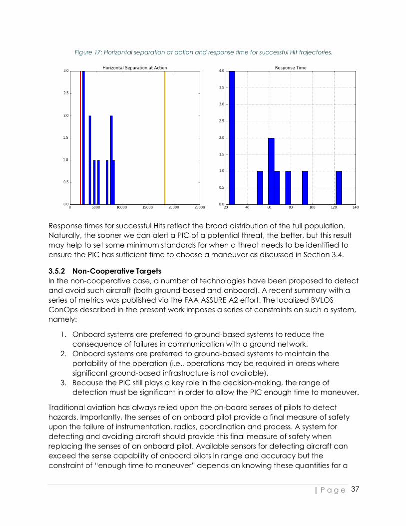
Figure 17: Horizontal separation at action and response time for successful Hit trajectories.
Response times for successful Hits reflect the broad distribution of the full population. Naturally, the sooner we can alert a PIC of a potential threat, the better, but this result may help to set some minimum standards for when a threat needs to be identified to ensure the PIC has sufficient time to choose a maneuver as discussed in Section 3.4.
3.5.2 Non-Cooperative Targets In the non-cooperative case, a number of technologies have been proposed to detect and avoid such aircraft (both ground-based and onboard). A recent summary with a series of metrics was published via the FAA ASSURE A2 effort. The localized BVLOS ConOps described in the present work imposes a series of constraints on such a system, namely:
1. Onboard systems are preferred to ground-based systems to reduce the consequence of failures in communication with a ground network.
2. Onboard systems are preferred to ground-based systems to maintain the portability of the operation (i.e., operations may be required in areas where significant ground-based infrastructure is not available).
3. Because the PIC still plays a key role in the decision-making, the range of detection must be significant in order to allow the PIC enough time to maneuver.
Traditional aviation has always relied upon the on-board senses of pilots to detect hazards. Importantly, the senses of an onboard pilot provide a final measure of safety upon the failure of instrumentation, radios, coordination and process. A system for detecting and avoiding aircraft should provide this final measure of safety when replacing the senses of an onboard pilot. Available sensors for detecting aircraft can exceed the sense capability of onboard pilots in range and accuracy but the constraint of “enough time to maneuver” depends on knowing these quantities for a
| P a g e
38
given sensor. Then, PIC reaction to information can be suitably captured in operations manuals and training.
Fortunately, in the present ConOps where air traffic density is expected to be low, and access to traffic feeds provided by Harris limits the non-cooperativity of the space, reasonable and achievable requirements can be defined for the range and accuracy. Specifically, if an onboard DAA system is able to alert the PIC of a potential incoming threat at a range of 3 NM from the sUAS, previous results show that the PIC can maneuver safely out of the way even in the limit where the accuracy of the information is limited to an approximate distance and heading.
Development of onboard sensor technology for detecting non-cooperative aircraft has faced three preeminent constraints
1. It is generally required that such sensors provide a 360o field of regard. 2. The air vehicles projected to provide the majority of UAS services are small and
severely restrict the size, weight and power (SWAP) available to such sensors. 3. “Enough time to maneuver” requires large detection ranges as described
above.
The interplay of these three constraints presents a significant technology challenge to applying traditional sensor approaches and has slowed the advance of regulation. As an example, RADAR has an intrinsically limited field of regard. Small, state of the art radar systems offer no more than 120o field of regard per sensor The radar equation places a physical limit on the amount of power required to achieve a range of 3NM. A multiple RADAR system that provides 360o field of regard to 3NM range has not been able to approach a feasible SWAP. Accordingly, development of passive sensors for detecting aircraft has been a commercial focus in the sUAS industry.
Of the available sensor technologies, only one has addressed the triple constraint enumerated above and only this one demonstrates the extended range required by the localized BVLOS ConOps. This system is the Passive Acoustic Non-Cooperative Collision Avoidance System (PANCAS) developed by SARA Inc. PANCAS detects the low-frequency sounds emitted by aircraft and that are reliably detectable at long ranges. The system has successfully demonstrated long-range detection of aircraft ranging from small ultralight aircraft to military transport aircraft. As a passive acoustic system, it is small and requires very little power. This system was tested during the Pathfinder experiments conducted at the Gypsum, KS site. Results (provided by SARA) are shown below in Figure 18. The system demonstrated the ability to reliably detect an incoming intruder at a range of 10 km (~5.4 NM) and 360o field of view with zero missed detections and no false alarms. This range is significantly longer than the visual detection distance (DEVLOS) of 2.37 NM (see Section 1.3.1) and is nearly double the recommended minimum detection distance.
The key potential risk associated with this system, as with all technologies of this type, is primarily lack of flight heritage that helps solidify an expectation of the final positional accuracy of the system (although, as described, field tests using the Pathfinder testbed

| P a g e
39
were remarkably successful). Mitigating this risk then, involves adopting a conservative approach to pilot maneuvering in response to alerting from the PANCAS system. In the scenario where the accuracy of the telemetry does not meet typical cooperative standards, leveraging the understanding obtained from operating within the BVLOS-VS construct becomes crucial as visual assessment of intruder trajectory is also subject to significant degradation in precision. The BVLOS-VS operation is able to be undertaken safely because of the conservative response of the PIC in that scenario, a similar conservative response (i.e. choosing to maneuver out of the airspace in the case of an intruder detected alert) can therefore be mandated in response to PANCAS alerts to ensure safety of the operation while flight heritage continues to be gathered. In the low population density, low air traffic density scenario, this conservative approach remains acceptable from a commercial standpoint.
Figure 18: PANCAS detect and avoid results at the Gypsum, KS Pathfinder experiments. Note that the circles
indicate the intruder position at the time of commanded evasive maneuver; the intruder was typically detected at 10 KM (~5.6 NM) from the sUAS position.
4 CONCLUSIONS AND RECOMMENDATIONS In conclusion, the Phase III field studies, in conjunction with the MITRE simulation efforts, were able to demonstrate that localized BVLOS operations in low risk environments can be conducted safely provided the following considerations are accounted for around:
• Operating Environment • Assistive Technology Requirements • Crew Experience and Training Requirements • sUAS Requirements • Summary: Key sUAS Technology Requirements

| P a g e
40
4.1 OPERATING ENVIRONMENT Table 13 lists the proposed operating environment conditions for low risk localized BVLOS. As described in Section 2.3, for the field trials the environment conformed to that permitted under BVLOS-VS operations, however, the success of participants in avoiding well-clear violations using the assistive technology allows for a shift away from those restrictions created by the limits of PIC vision.
Table 13: Operating environment for low risk localized BVLOS
Environment Requirement Low Risk Areas Operations will be contained to low risk areas in rural or
remote, sparsely populated areas. Meteorological Conditions
a) VFR conditions at the launch and planned landing location (work in all phases assumed launch and planned landing would occur within VLOS under Part 107 requirements).
b) Other meteorological conditions will be restricted to limitations specified in the flight manual of the sUAS used for the operation.
c) Weather conditions should be evaluated both prior to and during flight and verified acceptable across the planned operational area.
Time of Operation Day or night operations, provided suitable waiver is issued for the latter and any requirements for said waiver (i.e. anti-collision lighting on the sUAS) are fulfilled. As the operation is performed without visual contact by the PIC of either sUAS or manned aircraft, time-of-day is not a factor in determining PIC efficacy.
Minimal On-Field Distractions
Sources of noise pollution, in particular sources of mechanical noise such as generators and vehicles should be minimized. Distractions from authorized personnel on-site (i.e. background chatter) should be reduced.
Airspace Class Operations are restricted to Class G airspace. Air Traffic Operations will occur where air traffic is expected to be
low to extremely low. Specifically, as the research evaluated the operator’s ability to respond to a single aircraft, should there be multiple aircraft in the same region operators flying in localized BVLOS should be instructed to land immediately until the airspace is clear.
4.2 ASSISTIVE TECHNOLOGY REQUIREMENTS Recommended functionality requirements of the assistive technology are presented in Table 14 based on the results of the Phase III field trials.

| P a g e
41
Table 14: Assistive technology requirements for low risk localized BVLOS
Function Requirement Telemetry Assurance for Cooperative Aircraft
As the sUAS proceeds beyond the BVLOS-VS limit, the PIC can no longer detect incoming traffic with unaided vision. Therefore, the set of assistive technologies used for airspace surveillance must provide some level of current position and trajectory information for air traffic in the flight area. As discussed in Section 3.4.1, decisions made based on telemetry from cooperative traffic successfully prevent well-clear violation provided the telemetry has sufficiently low latency (< 1 s) and sufficiently high update rate. The NextGen surveillance data provided by Harris is an example of a fused data source which meets this requirement.
Telemetry Assurance for Non-Cooperative Aircraft
Since not all aircraft use ADSB or appear in flight data feeds, non-cooperative traffic must be detected through either onboard or ground based means. Therefore, in the near term we propose an alternate perspective, the use of a long-range detection system that can alert the PIC of non-cooperative traffic in the area in time for safe landing of the sUAS. The PANCAS system by SARA detailed in Section 3.5.2 is a lightweight, low-power onboard system that is capable of detecting manned aircraft at sufficient ranges to effect this operation.
Display Elements Understanding the effect in the field of different display elements on PIC threshold violation avoidance efficacy formed the core of the research results presented above. While the full set of elements will vary between assistive technology products, at a minimum the following should be included:
a) Ownship “bubble”: While not strictly necessary that this bubble conform to the suggested well-clear threshold of 2000 ft, placing a circle of fixed radius around the ownship icon helps to prevent horizontal scale confusion (see Section 3.3.1 and the operational risk assessment presented in the ASSURE A2 report).
b) Intruder relative altitude and horizontal separation: Prevents scale confusion (particularly vertically,
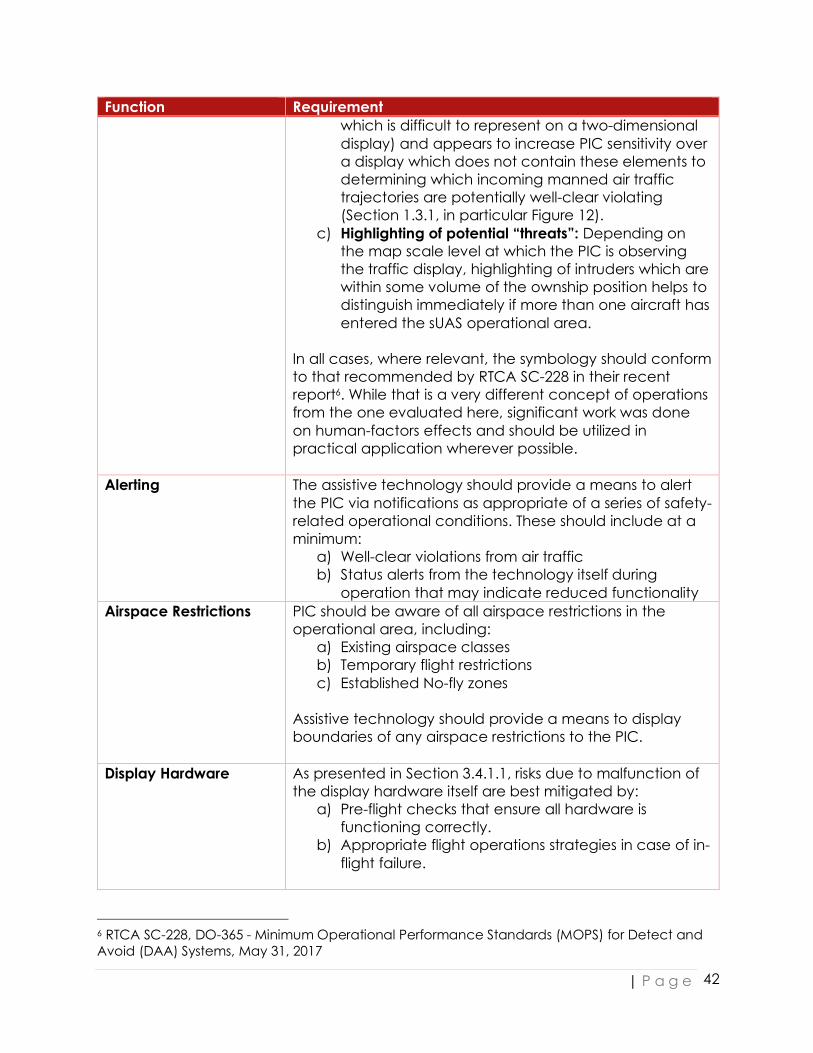
| P a g e
42
Function Requirement which is difficult to represent on a two-dimensional display) and appears to increase PIC sensitivity over a display which does not contain these elements to determining which incoming manned air traffic trajectories are potentially well-clear violating (Section 1.3.1, in particular Figure 12).
c) Highlighting of potential “threats”: Depending on the map scale level at which the PIC is observing the traffic display, highlighting of intruders which are within some volume of the ownship position helps to distinguish immediately if more than one aircraft has entered the sUAS operational area.
In all cases, where relevant, the symbology should conform to that recommended by RTCA SC-228 in their recent report6. While that is a very different concept of operations from the one evaluated here, significant work was done on human-factors effects and should be utilized in practical application wherever possible.
Alerting The assistive technology should provide a means to alert the PIC via notifications as appropriate of a series of safety-related operational conditions. These should include at a minimum:
a) Well-clear violations from air traffic b) Status alerts from the technology itself during
operation that may indicate reduced functionality Airspace Restrictions PIC should be aware of all airspace restrictions in the
operational area, including: a) Existing airspace classes b) Temporary flight restrictions c) Established No-fly zones
Assistive technology should provide a means to display boundaries of any airspace restrictions to the PIC.
Display Hardware As presented in Section 3.4.1.1, risks due to malfunction of the display hardware itself are best mitigated by:
a) Pre-flight checks that ensure all hardware is functioning correctly.
b) Appropriate flight operations strategies in case of in-flight failure.
6 RTCA SC-228, DO-365 - Minimum Operational Performance Standards (MOPS) for Detect and Avoid (DAA) Systems, May 31, 2017

| P a g e
43
4.3 CREW EXPERIENCE AND TRAINING REQUIREMENTS Operator (and other crew member, as applicable) recommended requirements in addition to those required under Part 107 are given in Table 15.
Table 15: Crew requirements for low risk localized BVLOS
Function Requirement Flight Experience As discussed in Section 3.4.1.3, a given operator’s flight
experience on the sUAS used for the operation is the single most significant factor in the correct choice and timing of evasive maneuvers. The recommendation for flight experience prior to qualifying to fly localized BVLOS operations is 30 total hours on the general type of system to be used (i.e., fixed-wing vs multi-rotor) including 15 to 20 hours on the specific equipment to be used.
BVLOS-VS Training As determined in Phase II, reconditioning VLOS trained PICs
to BVLOS operation should occur during in-field training with a BVLOS experienced trainer. The BVLOS-VS training requirements recommended remain applicable for the localized BVLOS ConOps and are as follows: PIC will receive BVLOS-VS training on the sUAS system to be used in accordance with recommendations in Section 1.3.1 specifically:
a) Training performed by BVLOS-VS -qualified instructor b) 5 to 6 sorties of varying length, at instructor’s
discretion, including at least one at near maximum available flight time of the sUAS to be used.
Assistive Technology Training
Sections 3.1.1 and 3.3.1 discussed the impact of training on the assistive technology system (particularly the display elements) and recommends both simulation and in-field training components. The purpose is to introduce the operator to use of the system in a variety of realistic potential operational scenarios. As in some cases, significant portions of Miss or Late-Action events were attributed to single participants, a practical performance evaluation component to the training is also highly recommended. This is consistent with recommendations made in the general BVLOS operational risk assessment prepared by the ASSURE A2 team.
BVLOS Flight Handbook Training
The final training component is to link the previous three requirements together with an operational profile. This BVLOS Flight Handbook training should cover:
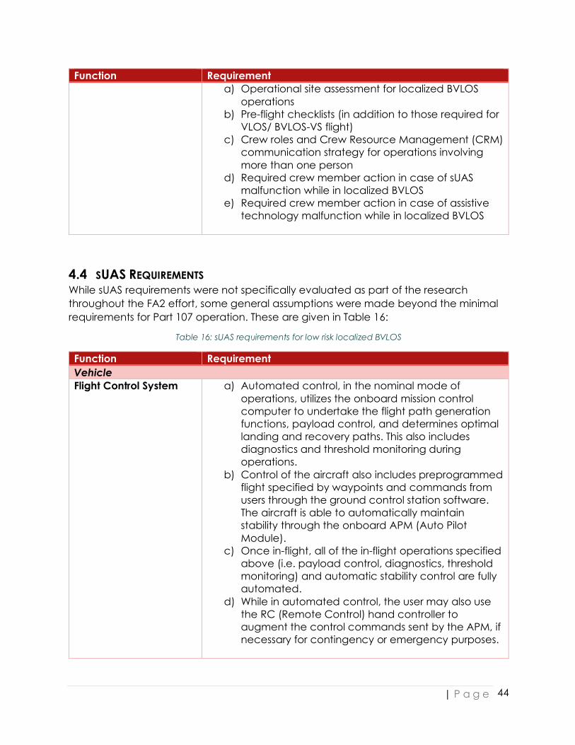
| P a g e
44
Function Requirement a) Operational site assessment for localized BVLOS
operations b) Pre-flight checklists (in addition to those required for
VLOS/ BVLOS-VS flight) c) Crew roles and Crew Resource Management (CRM)
communication strategy for operations involving more than one person
d) Required crew member action in case of sUAS malfunction while in localized BVLOS
e) Required crew member action in case of assistive technology malfunction while in localized BVLOS
4.4 SUAS REQUIREMENTS While sUAS requirements were not specifically evaluated as part of the research throughout the FA2 effort, some general assumptions were made beyond the minimal requirements for Part 107 operation. These are given in Table 16:
Table 16: sUAS requirements for low risk localized BVLOS
Function Requirement Vehicle Flight Control System a) Automated control, in the nominal mode of
operations, utilizes the onboard mission control computer to undertake the flight path generation functions, payload control, and determines optimal landing and recovery paths. This also includes diagnostics and threshold monitoring during operations.
b) Control of the aircraft also includes preprogrammed flight specified by waypoints and commands from users through the ground control station software. The aircraft is able to automatically maintain stability through the onboard APM (Auto Pilot Module).
c) Once in-flight, all of the in-flight operations specified above (i.e. payload control, diagnostics, threshold monitoring) and automatic stability control are fully automated.
d) While in automated control, the user may also use the RC (Remote Control) hand controller to augment the control commands sent by the APM, if necessary for contingency or emergency purposes.
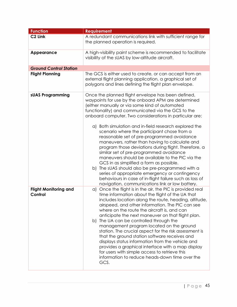
| P a g e
45
Function Requirement C2 Link A redundant communications link with sufficient range for
the planned operation is required.
Appearance A high-visibility paint scheme is recommended to facilitate visibility of the sUAS by low-altitude aircraft.
Ground Control Station Flight Planning The GCS is either used to create, or can accept from an
external flight planning application, a graphical set of polygons and lines defining the flight plan envelope.
sUAS Programming Once the planned flight envelope has been defined, waypoints for use by the onboard APM are determined (either manually or via some kind of automated functionality) and communicated via the GCS to the onboard computer. Two considerations in particular are:
a) Both simulation and in-field research explored the scenario where the participant chose from a reasonable set of pre-programmed avoidance maneuvers, rather than having to calculate and program those deviations during flight. Therefore, a similar set of pre-programmed avoidance maneuvers should be available to the PIC via the GCS in as simplified a form as possible.
b) The sUAS should also be pre-programmed with a series of appropriate emergency or contingency behaviours in case of in-flight failure such as loss of navigation, communications link or low battery.
Flight Monitoring and Control
a) Once the flight is in the air, the PIC is provided real time information about the flight of the UA that includes location along the route, heading, altitude, airspeed, and other information. The PIC can see where on the route the aircraft is, and can anticipate the next maneuver on that flight plan.
b) The UA can be controlled through the management program located on the ground station. The crucial aspect for the risk assessment is that the ground station software receives and displays status information from the vehicle and provides a graphical interface with a map display for users with simple access to retrieve this information to reduce heads-down time over the GCS.

| P a g e
46
4.5 SUMMARY: KEY SUAS TECHNOLOGY REQUIREMENTS Based on the above set of requirements there are 4 core pieces of technology that we recommend be incorporated for drones to safely fly BVLOS:
Key Technology Description 1. sUAS Tracking Hardware- and/or software-based methods of transmitting
live trajectory information for the sUAS being flown.
2. Real Time Manned Aircraft Data Feed
Real-time data feeds that transmit the location and trajectory of cooperative manned traffic that includes ADSB and radar feeds with < 1 s latency. For example, the Harris NextGen Surveillance Data feeds (described further in Section 3.4.1.2).
3. Detect and Avoid System
Hardware- and software-based methods that detect non-cooperative manned traffic at a minimum distance of 3 NM and with a 360o field of regard. For example, the SARA PANCAS system, which is capable of detecting non-cooperative targets at 5 NM (described further in Section 3.5.2) and offers a 360o field of regard.
4. Display A display that: provides the information in #1 to #3 above and enables algorithms to generate alerts (visible/audible) to the PIC via the display, allowing the PIC to maintain well-clear from manned aircraft and execute collision avoidance maneuvers if necessary.
Then the above represent a set of requirements for a commercially viable localized BVLOS ConOps that can meet required NAS safety standards and is realizable near-term. The overall operational profile as captured for any particular operator in their BVLOS flight procedures will need to be conservative. Specifically, there may be multiple scenarios in which the required action is to land the sUAS to preserve airspace safety. This is not an unreasonable requirement for technologies which are relatively new to use within an aviation context, and every hour of flight heritage gained is another set of data with which to continue to develop the risk profile and innovate solutions which can lead to further expansion in the permitted operations.

APPENDIX: PARTICIPANT QUESTIONNAIRES