path computation in multi-layer multi-domain...
TRANSCRIPT

Path Computation in Multi-Layer Multi-DomainNetworks?
Mohamed Lamine Lamali1, Helia Pouyllau1, and Dominique Barth2
1 Alcatel-Lucent Bell Labs France, Route de Villejust, 91620 Nozay, France{mohamed lamine.lamali, helia.pouyllau}@alcatel-lucent.com
2 Lab. PRiSM, UMR8144, Universite de Versailles45, av. des Etas-Unis, 78035 Versailles Cedex, France
Abstract. Carrier-grade networks have often multiple layers of pro-tocols. To tackle this heterogeneity, the Pseudo-Wire architecture pro-vides encapsulation and decapsulation functions of protocols over Packet-Switched Networks. At the scale of multi-domain networks, computinga path to support an end-to-end service requires various encapsulationsand decapsulations that can be nested but for which manual configura-tions are needed. Graph models are not expressive enough for this prob-lem. In this paper, we propose an approach using graphs and Push-DownAutomata (PDA) to capture the compatibility among encapsulations anddecapsulations along an inter-domain path. They are respectively mod-eled as pushes and pops on a PDA’s stacks. We provide polynomial algo-rithms that compute either the shortest path in hops, or in the number ofencapsulations and decapsulations to optimize interfaces’ configuration.
Keywords: Multi-layer networks, Pseudo-Wire, Push-Down Automata
1 Introduction
Most carrier-grade networks are composed of multiple layers of protocols (e.g.Ethernet, IP, etc.). Such layers are administrated by different control and man-agement plane instances. The Pseudo-Wire (PWE3) architecture [2] is a standardwhich aims to unify control plane functions in such heterogeneous environmentsallowing multi-layer services (e.g. Layer 2 VPN). It describes encapsulation (aprotocol is encapsulated in another one) and decapsulation functions, also called“adaptation functions”, emulating services (e.g. Frame Relay, SDH, Ethernet,etc.) over Packet-Switched Networks (PSN, e.g. IP or MPLS).
The management of these functions is achieved within each carrier’s networkdomain: when an encapsulation function is used, its corresponding decapsulationfunction is applied within the domain boundaries. In large-scale carrier-grade
? This work is partially supported by the ETICS-project, funded by the EuropeanCommission. Grant agreement no.: FP7-248567 Contract Number: INFSO-ICT-248567.
networks or in multi-carrier networks, restricting the management of adapta-tion functions to network boundaries might lead to ignore feasible end-to-endpaths and thus to refuse service demands. Hence, the path computation processthat precludes the signaling phase must encompass the notion of encapsula-tion/decapsulation compatibility : when a protocol is encapsulated into anotherat one node, it must be decapsulated at another, and the possibility to nest suchfunctions (e.g. Ethernet over MPLS over SDH). Furthermore, as such functionare manually configured on routers’ interfaces, minimizing their number wouldsimplify the signaling phase.
The authors of [8, 4] focused on the problem of computing a path in a multi-layer network under bandwidth constraints. In [10], we demonstrated that theproblem under multiple Quality of Service constraints is NP-Complete. As a firststep in our research, we focus on the problem of finding a path across multipledomains involving compatible - possibly nested - adaptation functions.
In this paper, we demonstrate that this reduced problem can be solved bya polynomial-time algorithm. We consider as an objective function, either thenumber of adaptation functions to simplify the signaling or the number of nodesto minimize the cost of a path. The proposed approach combines both graph andautomata theory: the encapsulation and decapsulation functions are designed aspushes and pops in a Push-Down Automaton (PDA) respectively. To determinethe shortest path in adaptation functions, such a PDA is transformed to bypasspath segments without such functions. The PDA or transformed PDA is thenconverted into a Context-Free Grammar (CFG) using the method of [7]. A short-est word, either corresponding to the shortest path in nodes or in adaptationfunctions, is generated from this CFG.
This paper is organized as follows: sec. 2 recalls the context of multi-layermulti-domain networks and the related work on path computation; sec. 3 pro-vides a formal definition of the problem; sec 4 explains the transformation froma network to a PDA; finally, sec. 5 details the different algorithms computingthe shortest path in nodes or in encapsulations/decapsulations.
2 Path computation in Pseudo-Wire networks
In order to mitigate multi-layer issues, some standards define the emulation oflower layer connection-oriented protocols over a PSN (e.g. Ethernet over MPLS,[12]). For instance, the layer 2 frames are encapsulated in layer 3 packets at onenetwork node and decapsulated at another, bursting the OSI model.
The PWE3 architecture [2] assumes an exhaustive knowledge of the networkstates. This assumption is also used in the multi-layer networking descriptionof [13] and is not valid in a multi-domain context. This issue has been identi-fied by the IETF PWE3 working group. The authors of [1] defined the multi-segment Pseudo-Wire architecture for multi-domain networks. The authors of[3] mention the problem of path determination and suggest the use of the PathComputation Element architecture (PCE) [5], which is adapted to the multi-domain context, to figure it out. It could be a control plane container for the
2

approach described in this paper, requiring some protocol extensions to add en-capsulation/decapsulation capabilities in the coding of the data model used byPCEs.Related work on path computation. In [4], the authors addressed the prob-lem of computing the shortest path in the context of the ITU-T G.805 recom-mendations on adaptation functions. They stress the lack of solutions on pathselection and the limitations of graph theory to handle this problem. In [8], theauthors addressed the same problem in a multi-layer network qualifying it as anNP-Complete problem. The NP-Completeness comes from the problem defini-tion as they allow loops across layers but under a limited bandwidth. They aimto select the shortest path in nodes and provide an exponential-time algorithmaccordingly. The model used in [8] is close to a PDA.
In the problem we consider, we exclude bandwidth constraints as the PCE ar-chitecture handles them already and propose a solution for minimizing the num-ber of encapsulations and decapsulations. Our algorithm does not allow loopswithout adaptation functions, the only loops that may exist involve encapsula-tions or decapsulations. Thus, minimizing the number of adaptation functionsin the path also leads to minimize the number of loops - and to avoid them ifa loop-free feasible path with less encapsulations exists. Our contribution is ageneralization based on graph and automata theory providing further theoreticalassets and a different modeling leading to a polynomial-time algorithm.Proposed approach. To the best of our knowledge no previous work has con-sidered this problem at the multi-domain scale. It induces to go further domainboundaries allowing multi-domain compatibility to determine a feasible inter-domain path: when an encapsulation for a given protocol is realized in one do-main its corresponding decapsulation must be done in another. Furthermore, weconsider two kind of objectives: either the well-known objective of minimizingthe number of nodes or the objective of minimizing the number of adaptationfunctions. This latter is motivated by the fact that it is equivalent to minimizethe number of configuration operations, which are often done manually and canbe quite complex. To express encapsulations and decapsulations, the networkmodel is converted into a PDA as the stack allows memorizing encapsulations.Hence, our approach encompasses the two shortest path problems either in nodesor in adaptation functions:
1. Convert a multi-domain Pseudo-Wire network into a PDA,(a) If the goal is to minimize the number of adaptation functions, transform
the PDA to bypass the “passive” functions (i.e. no protocol adaptation),(b) else let the PDA as is,
2. Derive a CFG from the PDA or the transformed PDA,3. Determine the “shortest” word generated by the CFG and4. Identify the shortest path from the shortest word.
3 Heterogeneous multi-domain network model
A multi-domain network having routers with encapsulation/decapsulation capa-bilities can be defined as a 3-tuple: a directed graph G = (V, E) modeling the
3

routers of a multi-domain network, we consider a pair of vertices (S,D) in Gcorresponding to the source and the destination of the path we focus on; a finitealphabet A = {a, b, c, . . . } in which each letter is a protocol; an encapsulationor a decapsulation function is a pair of different letters in the alphabet A:
– Figure 1(a) illustrates the encapsulation of the protocol x by the node U inthe protocol y;
– Figure 1(b) illustrates that the protocol x is unwrapped by the node U fromthe protocol y;
– Figure 1(c) illustrates that the protocol x transparently crosses the nodeU (no encapsulation or decapsulation function is applied). Such pairs arereferred as passive further in this paper.
We denote by ED and by ED the set of all possible encapsulation functions anddecapsulation functions respectively, (i.e., ED ⊆ A2). A subset P (U) of ED∪EDindicates the set of encapsulation, passive and decapsulation functions supportedby vertex U ∈ V. We define In(U) = {a ∈ A s.t. ∃b ∈ A s.t. (a, b) or (b, a) ∈P (U)} and Out(U) = {b ∈ A s.t. ∃a ∈ A s.t. (a, b) or (b, a) ∈ P (U)}. The setA(U) = {(a, a) ∈ P (U)} is the set of protocols that can passively cross node U .
(a) Encapsulation ofprotocol x in proto-col y, (x, y) ∈ P (U)
(b) Decapsulation of pro-tocol x from protocol y,(x, y) ∈ P (U)
(c) Passivecrossing,(x, x) ∈ P (U)
Fig. 1. Different transitions when a protocol crosses a node U
Considering a network N = (G = (V, E),A, P ), a source S ∈ V, a destinationD ∈ V and a path C = S, x1, U1, x
2, . . . , Un−1, xn, D where each Ui is a vertex
in V and each xi ∈ A ∪A (where A = {a : a ∈ A}).
– TC = x1 . . . xn represents the sequence of protocols which is used over thepath C. It is called the trace of C. For each xi:• xi = a and xi+1 = b or b, means that Ui encapsulates protocol a in b (a, b, b ∈ A ∪A)
• xi = a and xi+1 = b or b means that Ui unwraps protocol b from a• xi = a and xi+1 = a or a means that Ui passively transports a
– We denote HC the sequence β1, . . . , βn obtained from C s.t. for i = 1..n:• if xi = a ∈ A and xi+1 = b ∈ A or xi+1 = b ∈ A then βi = (a, b)• if xi = b ∈ A and xi+1 = a ∈ A\{b} or xi+1 = a ∈ A\{b} then βi = (a, b)
4

– We also denote MC = β′1, . . . , β′m obtained from HC by deleting each passive
transition βi s.t. βi = (a, a) and a ∈ A
Example. Consider the path C = S, a, U, b, V, b,W, a,D in the network illus-trated by Fig. 2(a). The sequence corresponding to C is HC = (a, b), (b, b), (a, b)and its trace is TC = abba. Finally, the well parenthesized sequence from C isMC = (a, b), (a, b).
Let ε denotes the empty word, and HC a sequence obtained from a path Cas explained above. The following definitions give a formal characterization ofthe feasible paths.
Definition 1. A sequence MC from HC is valid if and only if MC ∈ L where Lis the formal language recursively defined by: L = ε ∪ ((a, b).L.(a, b)).L for each(a, b) ∈ A2.
Definition 2. A path C is a feasible path in N from S to D if:
– U1, . . . , Un−1 is a path in G– the sequence MC from C is valid– for each i = 1..n:• if xi = a and xi+1 = b or b then (a, b) ∈ P (Ui)• if xi = a and xi+1 = b or b then (a, b) ∈ P (Ui)• if xi = a and xi+1 = a or a then a ∈ A(Ui)
The language L of valid sequences is known as the generalized Dyck language[11]. It is well-known that this language is context free but not regular. Thus,push-down automata are naturally adapted to model this problem.Example. The multi-domain network illustrated by Fig. 2(a) has 6 routers andtwo protocols labeled a and b. Adaptation function capabilities are indicatedbelow each node. In this multi-domain network, the only feasible path betweenS and D is S, a, U, b, V, b,W, a,D and involves functions (a, b) on U , (b, b) on V ,and (a, b) on node W .Problem definition. As explained above, our goal is to find a feasible multi-domain path. Furthermore, we set as an objective function either the size of thesequence of adaptation functions or the size of the path in number of nodes.Hence, the problem we aim to solve can be defined as follows,
minC |HC | or |MC | s.t. C is a feasible path
4 From the network model to a PDA
In this section, we address the conversion from a network to a PDA. The algo-rithm 1 takes as input a network N = (G = (V, E),A, P ) and converts it to aPDA AN = (Q, Σ, Γ, δ, S, ∅, {D}), where Q is the set of states of the PDA, Σ theinput alphabet, Γ the stack alphabet, δ the transition relation, S the start state,Z0 the initial stack symbol and D the accepting state, ε is the empty string. Theautomaton AN from N is obtained as follows:
5

– Create a state Ux of the automaton for each U ∈ V and each x ∈ In(U),except for S for which create only one state,
– An encapsulation of a protocol x in a protocol y by a node Ux is modeled asa push of the character x in the stack between the state Ux and its successorVy. It is denoted (Ux, < x, α, xα >, Vy)3 ,
– A decapsulation of y from x by the node Ux is modeled as a pop of theprotocol y from the stack. it is denoted (Ux, < x, y, ∅ >, Vy),
– The top of the stack is the last encapsulated protocol,– If the current state is Ux then the current protocol is x.
Example. Figure 2(b) is an example of output of the algorithm 1. The algorithmtransforms the network illustrated by Fig. 2(a) into a PDA of Fig 2(b). Forinstance, the link (U, V ) is transformed into the transitions (Ua, < a, Z0, aZ0 >, Vb) and (Ua, < a, b, ab >, Vb) w.r.t. adaptation capabilities of U and V .
Algorithm 1 Convert a network to a PDA
Input: a network N = (G = (V, E),A, P ), a source S and a destination DOutput: push-down automaton AN = (Q, Σ, Γ, δ, S, ∅, {D})(1) Σ ← A∪A ; Γ ← A∪ {Z0}(2) Create a single state for the node S(3) For each node U 6= S and each protocol x ∈ IN(U), create a state Ux
(4) For each state Ux s.t. (S,U) ∈ E and x ∈ Out(S)Create a transition (S,< ε, Z0, Z0 >,Ux)
(5) For each link (U, V )∈E s.t. U 6=S and for each (x, y)∈P (U) and each α∈Γ\{x}(5.1) If x ∈ A(U)∩ In(V ) Create a transition (Ux, < x, α, α >, Vx){passive trans.}(5.2) If x 6= y and y ∈ In(V ) Create a transition (Ux, < x, α, xα >, Vx){encap.}
(6) For each link (U, V ) ∈ E s.t. U 6= S and for each (x, y) ∈ P (U)(6.1) If x ∈ In(V ) Create a transition (Uy, < y, x, ∅ >,Vx){decap.}
(7) Create a fictitious final state D.(8) For each x ∈ In(D) and each α ∈ Γ\{x} Create a transition (Dx, < x, Z0, ∅ >,D)
Complexity. Each node U from the graph generates |In(U)| states, exceptthe source node S. A fictitious final state is added. Thus, the number of statesis at worst 2 + (|V| − 1) × |A| so in O(|V| × |A|). The worst case complexityof algorithm 1 is in O(max((|V| × |A|), (|E| × ((|A| × |ED|) + |ED|))))). Weassume that the network is connected, so |E| ≥ |V| − 1. Since ED is a subset ofA2, then |ED| < |A|2 and |ED| < |A|2. Thus, the upper bound complexity is inO(|E| × |A|3), which is also an upper bound for the number of transitions.
Proposition 1. Considering a network N = (G = (V, E),A, P ), a source S ∈V and a destination D ∈ V, the language recognized by AN is the set of tracesof the feasible paths from S to D in N .
3 Note that, even if x = a ∈ A, the transition has the form (Ua, < a, α, aα >, Vy).Characters in A are only used as input characters. Characters indexing states andpushed characters in the stack are their equivalent in A.
6
Sketch of Proof. The main idea is to show that a path C is feasible if and onlyif its trace TC is accepted by the PDA. Thus, for each feasible path there is asequence of transitions in the PDA that accepts its trace. And for each acceptedword, the sequence of transitions, which accepts this word, corresponds to afeasible path. The complete proof is available in the Appendix online [9].
5 The shortest feasible path
In sec. 4, we provided the method to build a PDA allowing to determine thefeasible paths. The next step is to minimize either the number of nodes or thenumber of adaptation functions. The method to minimize the number of nodesuses directly the PDA as described in sec. 5.1. But, to minimize the number ofadaptation functions, as detailed in sec. 5.2, the PDA is transformed in orderto bypass the sub-paths without any adaptation function. Then, a CFG derivedfrom the PDA (or the transformed PDA) generates words whose length is equiv-alent to the number of nodes (or to the number of adaptations). An algorithmbrowses the CFG to determine the shortest word. Finally, another algorithmidentifies the multi-domain path corresponding to this shortest word.
5.1 Minimizing the number of nodes
The number of characters in a word accepted by the automaton AN is thenumber of links in the corresponding feasible path (each character is a protocolused on a link). Thus the step of automaton transformation (sec. 5.2) shouldbe skipped. The automaton AN is directly transformed into a CFG, then theshortest word is generated as described in sec. 5.3. The corresponding feasiblepath is computed by the algorithm 4 described in sec. 5.3.
5.2 Minimizing the number of adaptation functions
To enumerate only encapsulations and decapsulations in the length of each word(and thus minimize adaptation functions by finding the shortest word accepted),a transformed automaton A′N in which all sequences involving passive transitionsare bypassed must be determined. The length of the shortest word accepted byA′N is the number of adaptation functions plus a fixed constant.
Let define Qa (a ∈ A) as Qa = {Vx ∈ Q|x = a}, and let AaN be the sub-
automaton induced by Qa. By analogy with an induced subgraph, an inducedsub-automaton is a multigraph with labeled edges such that the set of vertexis Qa and the set of edges is the set of transitions between elements of Qa.Since there are only passive transitions between two states in Qa, all paths inthe sub-automaton are passive. Let define P (Ux, Vx) as the shortest path lengthbetween Ux and Vx. This length can be computed by any well-known ShortestPath Algorithm. Let Succ(Vx) be the set of successors of Vx in the originalautomaton AN , i.e., Succ(Vx) = {Wy ∈ Q|∃(Vx, < x, α, β >,Wy) ∈ δ}.
7
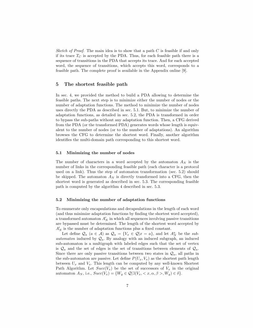
The algorithm 2 takes as input AN and computes the transformed automatonA′N = (Q′, Σ′, Γ ′, δ′, S′, ∅, {D′}). A′N is initialized with the values of AN . Then,the algorithm computes the sub-automaton for each character x ∈ A (step (1))and the length values P (Ux, Vx) for each pair of states in the sub-automaton (step(2.1)). Each path between a pair of states is a sequence of passive transitions.If such a path exists (step (2.2)), the algorithm adds transitions to δ′ from Ux
to each state in Succ(Vx) (steps (2.2.2) and (2.2.3)). These added transitionsare the same that those which connect Vx to its successors Wy, but with aninput character indexed by the number of passive transitions between Ux andVx, (i.e., P (Ux, Vx)) plus one (indicating that there is a transition sequencewhich matches with a sequence of protocols xx . . . x of length P (Ux, Vx) + 1).The indexed character is added to the input alphabet Σ′ (step (2.2.1)).Example. The algorithm 2 transforms the PDA in Fig. 2(b) into the PDA inFig. 2(c). the transition (Vb, < b2, a, ∅ >,Da) is added to bypass the sequence oftransitions (Vb, < b, a, a >,Wb) (Wb, < b, a, ∅ >,Da).
Algorithm 2 Transform automaton AN
Input: push-down automaton AN = (Q, Σ, Γ, δ, S, ∅, {D})Output: transformed push-down automaton A′N = (Q′, Σ′, Γ ′, δ′, S′, ∅, {D′})Q′ ← Q, Σ′ ← Σ, Γ ′ ← Γ , δ′ ← δ, S′ ← S, D′ ← DFor each x ∈ A
(1) Compute AxN
(2) For each Ux ∈ Qx and each Vx ∈ Qx s.t. Ux 6= Vx
(2.1) Compute P (Ux, Vx)(2.2) If P (Ux, Vx) <∞ {there is a path between Ux and Vx}
(2.2.1) Add xP (Ux,Vx)+1 and xP (Ux,Vx)+1 to Σ(2.2.2) For each Wy ∈ Succ(Vx)\{Ux} and each (Vx, < x, α, β >,Wy) ∈ δ
Add the transition (Ux, < xP (Ux,Vx)+1, α, β >,Wy) to δ′
(2.2.3) For each Wy ∈ Succ(Vx)\{Ux} and each (Vx, < x, α, β >,Wy) ∈ δAdd the transition (Ux, < xP (Ux,Vx)+1, α, β >,Wy) to δ′
Complexity. Steps (2.2.2) and (2.2.3) are bounded by O(|Q| × |δ|). Step (2.1)(computing the shortest path) is bounded by O(|Qx|2). Since the automatonis connected, |Qx| ≤ |Q| ≤ |δ| + 1. Thus, the complexity of each iteration inthe loop For (step (2)) is bounded by O(|Q| × |δ|). The number of iterationsof step (2) is in O(|Qx|2). However, a state cannot belong to two different sub-automata. The complexity of the algorithm 2 is in O(
∑x∈A |Qx|2 × |Q| × |δ|),
which is maximized when ∃x ∈ A s.t. |Qx| = |Q| and |Qx′ | = 0 for each x′ 6= x.Thus, the complexity of algorithm 2 is in O(|Q|3 × |δ|). In the network model,this is equivalent to O(|A|6 × |V|3 × |E|).
Let L(AN ) be the set of words accepted by AN , and let L(A′N ) be the set ofwords accepted by A′N . Let f : Σ′ → Σ∗ be a function s.t.:
– if xi = ai ∈ A′ then f(xi) = aa . . . aa︸ ︷︷ ︸i occurrences
8

– if xi = ai ∈ A′ then f(xi) = aa . . . aa︸ ︷︷ ︸i occurrences
The domain of f is extended to (Σ′)∗:
f : (Σ′)∗ → Σ∗ s.t. w′ = x1ix
2j . . . x
nk → f(w′) = f(x1i )f(x2j ) . . . f(xnk )
For simplicity, we consider that x and x1 are the same character. f(L(A′N ))denotes the set of words accepted by A′N transformed by f (i.e. f(L(A′N )) ={f(w′) s.t. w′ ∈ L(A′N )}).
It is clear that f is not a bijection (f(xixj) = f(xi+j)). So to operate thetransformation between L(AN ) and L(A′N ), we define g : Σ∗ → (Σ′)∗ s.t. :for each w = xx . . . x︸ ︷︷ ︸
i occurrences
yy . . . y︸ ︷︷ ︸j occurrences
. . . zz . . . z︸ ︷︷ ︸k occurrences
∈ Σ∗, g(w) = xiyj . . . zk.
In other words, w′ = g(w) is the shortest word in (Σ′)∗ s.t. f(w′) = w.
The following proposition shows the relation between the number of encap-sulations in AN and the size of a word accepted by A′N .
Proposition 2. The word accepted by AN which minimizes the number of pushesis f(w′), where w′ is the shortest word (i.e., with minimal number of characters)accepted by A′N .
Sketch of Proof. There is a linear relation between the length of a word acceptedby L(A′N ) and the number of pushes and pops involved to accept it, and thesame number of pushes and pops is involved to accept w′ (in A′N ) and f(w′) (inAN ). The complete proof is available in [9].
5.3 The shortest path as a shortest word
In order to find the shortest word accepted by AN (resp. A′N ), the CFG GN suchthat L(GN ) = L(AN ) (resp. L(A′N )) is computed. Backtracking from terminalsto the start symbol, the shortest sequence of derivations is then computed. Fromthe PDA to the CFG. The transformation of a PDA into a CFG is well-known. We adapted a general method described in [7] to transform AN (resp.A′N ) into a CFG GN = (N , Σ, SG,P) (resp.(N , Σ′, SG,P)) where N is the setof nonterminals (variables), Σ (resp. Σ′) is the input alphabet, SG is the initialsymbol (initial nonterminal) and P is the set of production rules. Nonterminalsare in the form [UXV ] where U, V ∈ Q (resp. Q′) and X ∈ Γ (resp. Γ ′).Theworst case complexity of this algorithm is in O(|δ|× |Q|2) (resp. O(|δ′|× |Q′|2)).W.r.t. the definition of the network, the upper bound is in O(|A|5 × |V|2 × |E|)and the number of production rules in the wost case is 1+ |Q|+(|δ|×|Q|2) (resp.O(|A|8 × |V|5 × |E|2) and 1 + |Q′|+ (|δ′| × |Q′|2)). The number of nonterminalsis bounded by O(|Q|2 × |A|) = O(|A|3 × |V |2) (resp. O(|Q′|2 × |A|) = O(|A|3 ×|V |2)). The interested reader can refer to [9] for the detailed algorithm.Example. This method transforms the PDA in Fig. 2(c) into a CFG. Figure 2(d)is a subset of production rules of the obtained CFG. This subset allows generatingthe shortest trace of a feasible path in the network in Fig. 2(a).
9
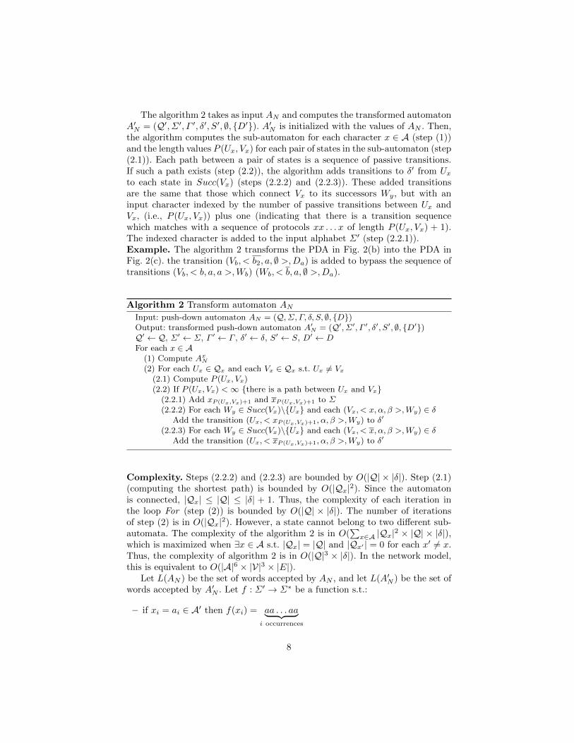
The shortest word generated by a CFG. To find the shortest word gen-erated by GN , a function ` associates to each nonterminal the length of theshortest word that it generates.
More formally, ` : {N ∪Σ ∪ {ε}}∗or {N ∪Σ′ ∪ {ε}}∗ → N ∪∞ s.t.:- if w = ε then `(w) = 0,- if w ∈ Σ or Σ′ then `(w) = 1,- if w = α1 . . . αn (with αi ∈ {N ∪ Σ ∪ {ε}} or {N ∪ Σ′ ∪ {ε}}) then `(w) =∑n
i=1 `(αi).The algorithm 3 computes the value of `([x]) for each [x] ∈ N .
Algorithm 3 Compute the values `([x]) for each nonterminal [x] ∈ NInput: GN = (N , Σ, SG,P) or (N , Σ′, SG,P)Output: `([x]) for each nonterminal [x](1) Initialize each `([x]) to ∞(2) While there is at least one `([x]) updated at the previous iteration do
(2.1) For each production rule [x]→ α1 . . . αn in P(2.1.1) `([x])← min{`([x]),
∑ni=1 `(αi)}
Proposition 3. The algorithm 3 terminates at worst after |N | iterations, andeach `([x]) ([x] ∈ N ) obtained is the length of the shortest word produced by [x].
Sketch of Proof. During each iteration, at least one `([x]) is updated to its cor-rect value, until all values are correct. The complete proof is available in [9].
Complexity. The complexity of the algorithm 3 is in O(|N | × |P|) which isO(|A|8 × |V |4 × |E|) (resp. O(|A|11 × |V |7 × |E|2)) in the network model.
There are several algorithms which allow generating a random word of somelength from a CFG. The boustrophedonic and the sequential algorithms describedin [6] generate a random labeled combinatorial object of some length from anydecomposable structure (including CFGs). The boustrophedonic algorithm is inO(n log n) (where n is the length of the object) and the sequential algorithmis in O(n2) but may have a better average complexity. Both algorithms use aprecomputed table of linear size. This table can be computed in O(n2). Thesealgorithms require an unambiguous CFG, but this requirement is only for therandomness of the generation. Recall that our goal is to generate the trace of theshortest feasible path. Thus, we do not take into consideration the randomnessand the distribution over the set of shortest traces.
In order to generate the shortest word in L(GN ), the boustrophedonic al-gorithm uses GN and `(SG) as input (`(SG) is the length of the shortest wordgenerated by GN ). Thus, the generation of the shortest word w (resp. w′) is inO(|w|2) (resp. O(|w′|2)) including the precomputation of the table.Example. The algorithm 3 gives `(SG) = 3. The boustrophedonic algorithmcomputes the shortest word with the production rules in Fig. 2(d). The derivation
is: SG
(1)
` [SZ0D](2)
` [UaZ0D](3)
` a[VbZ0Da][DaZ0D](4)
` ab2[DaZ0D](5)
` ab2a
10

Thus, the shortest word accepted by the transformed PDA is ab2a. And theshortest trace of a feasible path is f(ab2a) = abba.From the shortest word to the path. If the goal is to minimize the numberof nodes in the path, the algorithm 4 takes as input the shortest word w acceptedby AN . Otherwise, as w′ is the shortest word accepted by A′N and generated byGN , by prop. 2, f(w′) is the word which minimizes the number of pops andpushes in AN . In such a case it is the trace TC of the shortest feasible path Cin the network N . It is possible that several paths match with the trace TC = w(resp. f(w′)). In such a case, a load-balancing policy can choose a path.
The algorithm 4 is a dynamic programming algorithm that computes C. Itstarts at the node S and takes at each step all the links in E which match withthe current character in TC . Let TC = x1x2 . . . xn (xi ∈ A ∪ A). At each step i,the algorithm starts from each node U in Nodes[i] and adds to Links[i] all links(U, V ) which match with xi. It also adds each V in Nodes[i+ 1]. When reachingD, it backtracks to S and selects the links from D to S.Example. From the shortest trace abba, the algorithm 4 computes the onlyfeasible path in the network on Fig. 2(a), which is S, a, U, b, V, b,W, a,D.
Algorithm 4 Find the shortest path
Input: Network N and TC
Output: Shortest path C(1) Nodes[1]← S ; i← 1(2) While D is not reached do
(2.1) for each U ∈ Nodes[i] and each V ∈ V s.t. (U, V ) ∈ E do(2.1.1) If xi ∈ A, xi ∈ Out(U), xi ∈ In(V ) and (xi−1, xi) ∈ P (U)
(2.1.1.1) Add (U, V ) to Links[i] and V to Nodes[i+ 1](2.1.2) If xi ∈ A, xi ∈ Out(U), xi ∈ In(V ) and (xi, xi−1) ∈ P (U)
(2.1.2.1) Add (U, V ) to Links[i] and V to Nodes[i+ 1](2.2) i+ +
(3) Backtrack from D to S by adding each covered link in the backtracking to C.
Complexity. The while loop stops exactly after TC steps, because it is surethat there is a feasible path of length |TC | if TC is accepted by the automatonAN . At each step, all links and nodes are checked in the worst case. Thus, thealgorithm 4 is in O(|TC | × |V| × |E|) in the worst case.
6 Conclusion
In this paper, we presented a new model for heterogeneous networks involv-ing automata theory to provide the shortest path in number in nodes or inencapsulations/decapsulations. The proposed solution can be applied over thePseudo-Wire architecture [2], but also over other network architectures which in-volve adaptation functions and protocol changes. The different algorithms of ourmethodology have polynomial upper-bounds as summarized by Table 1. These
11
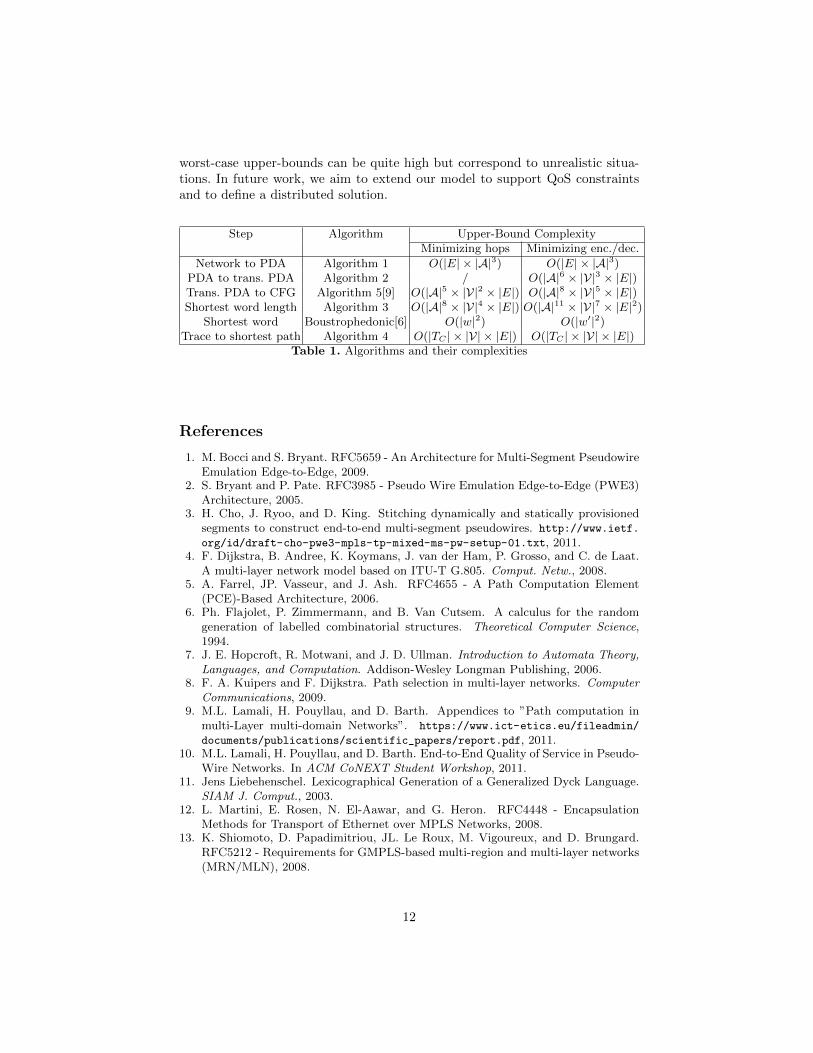
worst-case upper-bounds can be quite high but correspond to unrealistic situa-tions. In future work, we aim to extend our model to support QoS constraintsand to define a distributed solution.
Step Algorithm Upper-Bound ComplexityMinimizing hops Minimizing enc./dec.
Network to PDA Algorithm 1 O(|E| × |A|3) O(|E| × |A|3)PDA to trans. PDA Algorithm 2 / O(|A|6 × |V|3 × |E|)Trans. PDA to CFG Algorithm 5[9] O(|A|5 × |V|2 × |E|) O(|A|8 × |V|5 × |E|)Shortest word length Algorithm 3 O(|A|8 × |V|4 × |E|) O(|A|11 × |V|7 × |E|2)
Shortest word Boustrophedonic[6] O(|w|2) O(|w′|2)Trace to shortest path Algorithm 4 O(|TC | × |V| × |E|) O(|TC | × |V| × |E|)
Table 1. Algorithms and their complexities
References
1. M. Bocci and S. Bryant. RFC5659 - An Architecture for Multi-Segment PseudowireEmulation Edge-to-Edge, 2009.
2. S. Bryant and P. Pate. RFC3985 - Pseudo Wire Emulation Edge-to-Edge (PWE3)Architecture, 2005.
3. H. Cho, J. Ryoo, and D. King. Stitching dynamically and statically provisionedsegments to construct end-to-end multi-segment pseudowires. http://www.ietf.
org/id/draft-cho-pwe3-mpls-tp-mixed-ms-pw-setup-01.txt, 2011.4. F. Dijkstra, B. Andree, K. Koymans, J. van der Ham, P. Grosso, and C. de Laat.
A multi-layer network model based on ITU-T G.805. Comput. Netw., 2008.5. A. Farrel, JP. Vasseur, and J. Ash. RFC4655 - A Path Computation Element
(PCE)-Based Architecture, 2006.6. Ph. Flajolet, P. Zimmermann, and B. Van Cutsem. A calculus for the random
generation of labelled combinatorial structures. Theoretical Computer Science,1994.
7. J. E. Hopcroft, R. Motwani, and J. D. Ullman. Introduction to Automata Theory,Languages, and Computation. Addison-Wesley Longman Publishing, 2006.
8. F. A. Kuipers and F. Dijkstra. Path selection in multi-layer networks. ComputerCommunications, 2009.
9. M.L. Lamali, H. Pouyllau, and D. Barth. Appendices to ”Path computation inmulti-Layer multi-domain Networks”. https://www.ict-etics.eu/fileadmin/
documents/publications/scientific_papers/report.pdf, 2011.10. M.L. Lamali, H. Pouyllau, and D. Barth. End-to-End Quality of Service in Pseudo-
Wire Networks. In ACM CoNEXT Student Workshop, 2011.11. Jens Liebehenschel. Lexicographical Generation of a Generalized Dyck Language.
SIAM J. Comput., 2003.12. L. Martini, E. Rosen, N. El-Aawar, and G. Heron. RFC4448 - Encapsulation
Methods for Transport of Ethernet over MPLS Networks, 2008.13. K. Shiomoto, D. Papadimitriou, JL. Le Roux, M. Vigoureux, and D. Brungard.
RFC5212 - Requirements for GMPLS-based multi-region and multi-layer networks(MRN/MLN), 2008.
12

(a) Network
(b) Corresponding PDA
(c) Transformed PDA
(d) Subset of GN which generates TC
Fig. 2. Example
13