past present and future of urban cable propelled people movers
DESCRIPTION
presente pasado y futuro de transportadores de personasTRANSCRIPT

Journal ofAdvanced Transportation, Vol. 33, No. 1, pp. 51-82
The Past, Present, and Future of Urban Cable Propelled People Movers
Edward S. Neumann
The evolution of urban cable propelled people mover technology from the early 1800's through the 1990's is reviewed, with emphasis on systems developed since 1980. Technologies can be classified by the means of vehicle support and the type of service provided. The simplest systems serve as shuttles moving back-and-forth between a pair ofterminal stations; more complex systems feature vehicles which are launched continuously at short headways. Advances have occurred in the design and aesthetics of guideways, vehicle operating speed, the spectrum of capacities available, and automated features. The characteristics of the individual systems in urban environments throughout the world are described.
Introduction
As an assistive device to facilitate the movement of goods, the rope may predate the wheel. Contemporary cable propelled transportation systems use a flexible wire rope (frequently referred to as a haul rope) to transmit motive forces to vehicles supported on a guideway. Haul ropes are constructed by splicing together the ends of a section of cable to form a loop. Motive force is imparted to the loop through powered drive bullwheels, around which the cable passes. Friction forces developed between the cable and bullwheel keep the rope from slipping as the bullwheel turns. The amount of force that can be imparted to the rope depends on the tension in the rope, the wrap angle of the rope around the bullwheel, and the coefficient of friction. Aerial tramways - a subset of ropeway technology - also utilize a stiff rope (frequently referred to as a truck rope) as a guideway to support the vehicles. Aerial tramway vehicles are suspended below the track rope. When vehicles are bottom-supported and run on rails, the cable system may be referred to
Dr. Edward S. Neumann is Professor and Chair of the Department of Civil and Environmental Engineering, University of Nevada Las Vegas, Las Vegas, Nevada, USA. Received October 1998; Accepted December 1998

52 Edward S. Neumann
as either ajimicular, an incline, or occasionally a tram. As a structural form, wire rope offers the advantages of flexibility and compactness. In order to be used as a guideway, however, wire rope needs to be extremely strong and relatively stiff, which may limit flexibility to the point where no curvature is feasible other than a normal catenary sag. .For certain performance requirements (moderate capacity and speed) and under certain environmental conditions (steep slopes, long spans, and favorable alignment), cable propelled technoIogy may be both economically and technologically superior to technologies featuring self-propelled vehicles. Recent innovations in cable transportation are improving the compatibility of cable propulsion with urban environments, and increasing its ability to penetrate the urban market for APMs.
Major classification variables for urban cable technologies are 1 .) the method of vehicle support, and 2.) the type of service provided (Table 1). Vehicle size can be used as a second level of classification (in the table, TU refers to "transport unit", which may consist of a single vehicle or a train of vehicles). Vehicles may be supported from the bottom via a guideway (usually rigid), or suspended below a guideway (usually a track rope). Bottom support may be accomplished by steel wheel on rail, pneumatic tire on concrete, rubbedplastic wheel on a steel I-beam, or levitation. The level of service provided is one of three types. Reversible systems involve a single vehicle or a pair of vehicles which shuttle back-and-forth between stations at the ends of the guideway alignment. Vehicles are permanently attached to the cable, which accelerates, decelerates, and then changes direction of motion in order to shuttle vehicles back and forth between the stations. Systems featuring continuous service operate by launching vehicles from terminals at fiequent intervals. Vehicles are not permanently attached to the haul rope, but are accelerated by mechanical means to the velocity of the haul rope and clamped to it. At stations, vehicles are detached from the haul rope and decelerated. The third type of service is pulsed, which may be thought of as a hybrid between reversible and continuous service. Vehicles are permanently attached to the haul rope, which is accelerated and decelerated. However, the rope does not reverse direction as it would in the case of a reversible system, but always moves in the same direction. This type of technology is suited to activity center applications requiring more than two terminal stations. But station spacing is severely constrained; pulsed systems can effectively serve stations located between the end points of an alignment only if all the stations are spaced at equal distances apart. Vehicles then can be spaced along the haul rope at the same distances apart


54 Edward S. Neumann
as the stations, so that every time the rope stops, a vehicle is adjacent to a station platform.
Cable propelled systems can be as fblly automated as systems with self- propelled driverless vehicles, and provide a high level of service at a lower cost. Cable systems are driverless and can be operated by one person who monitors operations from a central control room. Because the vehicles do not contain motors, suspensions do not have to be as heavy, and the vehicles weigh less than self-propelled vehicles of equal capacity. Because vehicles are lighter, guideways do not have to be as massive, and construction costs are lower. Having one large source of propulsion rather than many smaller sources (e.g. motors on each vehicle) also reduces cost. One of the simplifications possible with cable technology is the detection of vehicle location and speed. Since vehicles are attached to a rope, their position can be known with high certainty, and rope velocity can be monitored easily. Other automated features can include door opening and closing, vehicle start- up and acceleration, spacing and headway control, vehicle deceleration and braking, and fault error detection and analysis.
Due to passenger wait time, reversible systems featuring conventional wire haul ropes offer the greatest advantages for alignments less than about 1,500 m length (4922 ft). At greater distances, wait times become longer than many passengers are willing to tolerate. Detachable systems serve the upper range of distance for cable, which appears to be about 5,000 m (16,405 ft). A wide range of passenger capacities are feasible. With simple shuttle systems, capacities can be doubled by adding a second, parallel system or coupling second or third vehicles into trains. With detachable systems, capacity increases can be accomplished by adding more vehicles or increasing rope speed. Several systems are available which can negotiate curves with radii as low as 39 m (98.4 ft), a necessity for urban applications, especially those which involve the retrofitting of a guideway through an existing development. Figure 1 plots the lengthcapacity envelope for the existing and planned reversible shuttle systems mentioned in the paper. Though continuous systems are needed to serve long alignments, figure 1 reveals that many continuous systems can be found in the same length- capacity niche occupied by reversible systems.

The Past, Present, and Future of Urban Cable ... 55
c o o 0
0 0 v)
0
0
.G
C
0
0 0
0
0 0 0 0 0 0 0 0 0 0 0 0 0 0 0
03 (D * (v
<
s
0 0 0 *
0 0 0 0
0 0 0 (v
0
8 T-
O

56 Edward S. Neumann
Prior to 1980
Though the earliest known wire rope was unearthed at Pompeii, it was not until 1834 that wire rope was used successfully, in a mining operation in the Harz Mountains of Europe [Frenkiel, 19661. In 1839, the first wire rope factory opened in Sweden, and in 1840 a factory opened in Cologne.
In 1856, Robinson, an Englishman, obtained the first patent for the design of material aerial ropeways using wire rope, but aerial ropeways were not built using this patent until 1867. In 1861, Cypher built a timber- supported ropeway for a mine in Colorado. The first passenger carrying aerial ropeway was constructed in Germany in 1866 to inspect turbine installations on the Rhine. The first aerial passenger ropeway in the United States was built in 1893 to cross the Tennessee River at Knoxville. Aerial ropeway construction accelerated in Europe during World War I to carry weapons, munitions, and wounded soldiers.
The first funicular ropeway (bottom supported vehicles) was invented by Stephenson in England in 1825 to haul a steam engine up a slope of 2%. In 1840, the first large-scale passenger movements by cable traction occurred in London wlton, 19821. The track was relatively flat and 6.03 km (3.75 miles) long. This system was the precursor of the cable car, which did not appear in America until 1873, when George Hallidie opened a system in San Francisco. Hallidie's father had taken out a British wire rope patent in 1835, but the evolution of wire cable in the United states was strongly influenced by bridge builder John Roebling, who began manufacturing wire rope in Pittsburgh in 1841. In the United States, inclines began operating as early as 1834 in Pittsburgh, using hemp rope. The hemp rope was replaced by Roebling's wire rope when it became available. Two of the Pittsburgh inclines are still operating. In Europe, passengercarrying hniculars, capable of ascending very steep grades, developed from rack railways. The first one opened in 186 1 at Dusino, Italy.
During the last half of the 19th Century, extensive networks of horse- drawn railways were built in many large American cities. Duringthe 1 8 8 0 ' ~ ~ many were replaced by cable street railways. The impetus for cable traction was the low speed, high cost, high mortality rate, and high fecal output of the horses being used on street railway systems. The feces presented a severe health hazard because it contained the tetanus virus, and there was no cure for tetanus wlton, 19821. Gradients and weather conditions also were factors in some cities. Gradients were the major reason for installing a cable system in San Francisco. The wear on the cable and grips were significant

The Past, Present, and Future of Urban Cable ... 57
and costly, however, and the cable traction systems that spread rapidly throughout the United States were quickly replaced by electric traction streetcars in the 1890's.
Following the brief period when cable cars were used in many cities, cable powered transportation assumed an insigntficant role in both urban crt rural public transportation in America. Though cable propulsion was used in mining operations to move coal and ores, the civil engineers who were developing the nation's rural and urban transportation networks were basically ignorant of it. It was not until after the end of World War II that cable systems for moving people began to reappear in America. However, the systems did not appear in cities - they appeared on ski slopes.
Cable transportation continued to evolve in Europe. During the early decades of the 19OO's, aerial and funicular systems grew in number in the Alpine areas of France, Germany, Italy, Switzerland, and Austria. In these areas of Europe, engineers were being trained in the art and science of cable transportation. Most of the systems constructed were utilitarian, but some of the systems were used for downhill (Alpine) skiing. American soldiers who had been trained in Colorado during World War I1 for mountain warfare in Europe, and had developed skiing abilities, returned from the war with an interest in establishing ski slopes in America. Many of the European firms that had designed and developed utilitarian cable systems applied their expertise to ski area systems, and found a growing market in both Europe and America.
In ski areas where the need was for an aerial passenger tramway or a funicular, the existing technology could be applied directly. However, the large aerial systems and funiculars were expensive and did not have high passenger capacities since they functioned by shuttling a pair of vehcles back and forth between two stations, one at each end of the rope. The Ionger the distance between the terminals, the longer the travel time and the waiting time in the stations, and the fewer the number of skiiers that could be camed onto the slopes. The solution to this problem at the lower end of the cost spectrum was the chair 1% which provides empty vehicles (chairs) every few seconds. Chairs are permanently attached to a single rope which serves both as a haul rope and a track rope. The rope moves slowly enough for skiers to board in the loading terminal. However, the low rope speed may cause travel times to be long. At the upper end of the cost spectrum, the solution was the detachable gondola. It consists of vehicles that normally carry between six and eight passengers (higher capacity vehicles are produced). Vehicles move slowly through a passenger loading area, and are then attached to a rapidly

58 Edward S. Neumann
moving haul rope. At the opposite terminal, the vehicles are detached from the haul rope and decelerated by mechanical devices. A stiff track rope supported by towers may be necessary if the forces in the haul rope are too great to allow it to simultaneously transmit the propulsive forces and carry the weight of the vehicles. This could be the case if the vehicles are large and heavy, spaced closely together, the span lengths are long, or the total rope length is long. If the vehicles are small, spaced krther apart, span lengths are not long, and the overall alignment is not long, then the haul rope may be capable of supporting the weight of the vehicles. Continuous systems facilitate longer hauls and higher capacities than shuttle systems, and continuous systems featuring detachable vehicles offer higher operating speeds and better levels of service than continuous systems which have vehicles permanently attached to the haul rope.
Despite the rapid growth of ski systems, virtually no cable-powered systems appeared in the urban areas of North America, except for expositions, fairs, and some amusement park rides. The first, and only, 20th Century American urban aerial tramway system featuring conventional cable support and motive power was opened in New York City, NY, in 1977 to connect Roosevelt Island with downtown Manhattan and is still operating (figure 2) veurnann, 19891. Constructed by VSL Corporation and featuring Von Roll equipment, a pair of suspended vehicles, each with a capacity of 125 passengers, shuttle back and forth along a 361 m (958 ft) guideway consisting of four heavy track ropes (2 ropes per vehicle). The operating speed is 7.3 m/s (24 Wsec). Capacity is 1500 passengers per hour per direction. In the early 199O's, a subway station was opened to connect Roosevelt Island with Manhattan and Brooklyn. While it is viewed as an important component of the transportation system serving Roosevelt Island, it no longer is a key means of access to the Island, and preservation of it hinges upon its recreational value, nostalgia, and convenience for those making short trips to Manhattan. Except for Roosevelt Island, aerial tramways have not been implemented as solutions to public transportation problems in North America. In only two other cities, Detroit, MI, and Pittsburgh, PA, was it given study and proposed as a means of creating an additional link across the rivers in those cities veumann, 19901.
Reversible Systems Since 1980
The 1980's witnessed growth in the number of urban cable installations featuring reversible systems and departures from conventional technology.

The Past, Present, and Future of Urban Cable ... 59
Figure 2. Roosevelt Island aerial tramway (courtesy VSL).

Table 2. Reversible Systems
VC4l New Y& NY 361 (958) 1500 126 I 2 7.3 (24) 2 Aaial Tnm
VSL C i m u I. L.r V e g s NV 401 (1315) 1639 so I 2 6.1 (20) 2 DiSNHlCd
VSL Memphis. TN 457 (1500) 3600 I80 I 2 8.1 (26.7) 2 s u m
RolWSL
Olis S d a u r Aunria 1300(4265) 2000 135 I 2 1 1 . 1 ( 3 6 . n 4
I
I VSL I C i m u N m h R m , NV 1 1 4 0 (460) I1363 I 5 0 I I 1 1 I 4.1 (13.3) I 2 I I O t i s Hubour IrludTunpa. FL 762 (2500) 3OOO loo I 2 11.1(36.7) 2
Otis Sun Ci. Swh Africa 1710(5610) 2400 100 I 2 1 1 . 1 (36.7) 3
VSL Rim NV 550 (1740) 550 60 I I 7 (23) 2 ~p~ ~ p ~ p ~
Otis N a h Akpal Jqmn 319 (1047) 8722 I50 I 4 5.6 (18.4) 2 4-
VSLlifl Mirap. Lu V g r r . NV 305 (1WO) 18W M) 2 I 8 (26.4) 2
Ot is Cincinuti Airprl. OH 358 (1174) 5600 71 3 2 11.6(38.1) 3
Y.nuJ; Murmdh Mumlain.. CA 1219 <*ooo) N 28 2 I 10 (33) 3 N d o p n t i n i
.ylcm
~~
Dopphy M d a 1 a y B . y I .LuVegu,NV 838 (2749) 1900 32 5 I 10 (32.9) 2
Doppdnuy M d a l a y B . y I I . L u V ~ N V 838 (2749) 1300 32 5 I 10 (32.9) 4
(his M i m p o l i i Air@. MN 335 ( 1 1 0 0 ) 2600 65 I 2 8.9 (29.3) 2

The Past, Present, and Future of Urban Cable ... 61
The majority were constructed in urban resort settings and were modifications of traditional funicular technology. Funiculars and inclines have been constructed in many hilly European cities by a variety of firms since the turn of the century. Table 2 lists the key design characteristics of reversible systems discussed in this paper.
VSL Metro Shuttle. One of the first of the new urban systems opened in Memphis, TN, in 1982 to connect a public park on an island in the Mississippi River with parking facilities along the bank [Neumann, 19901. The VSL Metro Shuttle 6000 features two vehicles suspended from a rigid guideway; the vehicles shuttle back and forth between the two terminals at the ends using propulsive technology similar to that for suspended aerial tramways. The guideway initially was constructed to house a walkway and a system of self-propelled vehicles. However, costs prohibited the development of a system of self-propelled vehicles. Cable propulsion was chosen instead. The guideway features a 45 degree, 88.4 m (290 ft) radius horizontal curve.
In 198 1 , VSL constructed a bottom-supported system at Circus-Circus in Las Vegas, NV, to connect the main hoteVcasino with the Manor Terminal located in the rear [Neumann, 19901. It featured 2 vehicles on a single track guideway. A passing s i d q at the midpoint of the alignment allowed the two vehicles to pass each other. While the propulsion system and the concept of having a single track with a passing siding were typical of classic hnicular systems, the support of the vehicles was significantly different. Rubber tires were used on a concrete guideway in a manner similar to the technology being used for self-propelled vehicles for airport systems. The advantages of rubber tires over a steel-wheel were weight reduction for the vehicle, and consequently smaller loads on the guideway and a reduction of capital costs, as well as better traction. However, the guideway was relatively massive. A second, similar system was constructed by VSL at the same resort in 1985 to link the main casino with a new high-rise structure (figure 3). Since only one vehicle was used, a more efficient wheel-guideway interface could be designed. The first VSL system had to allow for switching at the bypass, and lateral guidance of the vehicle was accomplished by horizontally mounted rubber tires which exerted pressure laterally on the outside vertical walls of the guideway. This required the constrilction of vertical walls on the outside edge of the guideway. The second system did not require a bypass and achieved horizontal guidance by means of a vertical I-beam located in the center of the guideway. Horizontal guidance wheels exerted pressure

62 Edward S. Neumann
medially into the I-beam. The guideway could be lighter in weight. Both systems could be run virtually around the clock, and the second system has been operated continuously for several days without any downtimes for maintenance. The first system was tom down in 1996 to make way for new construction, but the second system still is in operation.
Figure 3. Circus-Circus 11, with stub end of dismantled Circus-Circus I at right (photo by author)
During 1985, VSL also constructed two virtually identical systems at the Circus-Circus resort in Reno, NV. In 1990, VSL constructed a single-vehicle shuttle at Primm, NV, to connect a pair of casino-resorts on the Nevada-California state line south of Las Vegas. Besides some mechanical refinements in the propulsion system, a vehicle guidancdsuspension system was developed which enabled the guideway to be designed to resemble a monorail (figure 4). In contrast to earlier guideways, which resembled an elevated roadway, the new guideway was only 1.52 m by 0.30 m (5 ft by 3 ft). In 1993, a system designed by VSL and Lift Engineering was opened to connect the Treasure Island and Mirage resorts in Las Vegas (Neumann,

The Past, Present, and Future of Urban Cable ... 63
1998). The guideway is similar to the structures designed for the Circus- Circus systems, though more aesthetically appealing.
Figure 4. Pimmadona vehicle and guideway (courtesy VSL)
OTIS Shuttle. The unique feature of Otis technology is its method of vehicle support. Instead of using wheels, vehicles are supported by “Hovair” support, cushions of air generated from circular rubber air pads mounted beneath the vehicles [Neumann, 19901. Vehicles float approximately .025 to .051 mm (.001 to .002 inches) above the guideway due to a pressure differential of 210.9 g/cm (3 psi). There were several reasons for using air suspension. First, it eliminates point Ioack on the guideway, which facilitates lower guideway construction and maintenance costs. Second, vehicle weight can be lowered since wheel and propulsion assemblies are not needed. Third, surface wear is eliminated since the vehicle does not touch the guideway. A smooth ride is an additional benefit. One of the features of the vehicles is a

64 Edward S. Neumann
modular design which facilitates capacity increases via the insertion of additional modules. By extending the vehicles or adding additional vehicles to create trains, one-way hourly capacities can be increased. In 1996 the firm linked with POMA of France, a wellestablished manuEdcturer of ski area systems, in order to combine technologies and market a hybrid system. This is discussed later.
Otis had substantial experience with cable propulsion in the elevator market, and also an extensive background in urban high-rise development. For Otis, it was quite logical to view a cable propelled APM as a horizontal elevator. A car could remain inactive until a passenger pushed a button in a station to summon a vehicle. Upon amval of the vehicle, the doors would open automatically, close, and the cable would pull the vehicle to the other end of the line. Motors and station door assemblies used in elevators could be used for the People Mover. Also, elevator maintenance personnel servicing Otis elevators in the area could double as maintenance personnel for the People Mover, and be available on-call for unexpected downtime events.
In 1984, Otis opened a cable propelled system in Serfaus, Austria, for skiers. It can be considered an urban system because it features an alignment that moves individuals underneath the downtown of a city and serves at one end a parking area, and at the other end the base of the ski slopes. Otis opened similar systems at Harbour Island, in Tampa, Florida, in 1985 and Sun City Resort in Bophuthatswana in 1986. The Tampa and Sun City systems feature two vehicles on a single lane guideway with a bypass section at midpoint; the Serfaus system features two vehicles operating on a double lane guideway. The Tampa system serves two stations, the Sun City system three stations, and the Serfaus system four stations.
In 1992, Otis opened a system at Narita Airport near Tokyo. Four independent, parallel systems were constructed, which provided a capacity of 8772 passengers per hour per direction. In 1994, a system was opened at Cincinnati/Northern Kentucky International Airport [Venter, 19961. Three stations serve two concourses and the terminal. Two independent guideways are utilized. In 1997, a system opened at the J. Paul Getty Center near Los Angeles (figure 5) . It features two 3-car trains which pass each other at a mid-point bypass. The Getty system has a maximum gradient of 8% and a minimum gradient of 3%, making it the system having the highest gradient to which Otis technology has been applied.
Otis’ most recently completed project is at the Mystic Center in Boston, MA. However, it does not feature Hovair suspension. Otis constructed the

The Past, Present, and Future of Urban Cable ... 65
Mystic Center system with conventional steel rails and steel wheels. Vehicle doors are located on the front and rear of the vehicles, which eliminates the need for station platforms along the sides of the vehicle. Passengers can board from the back of the vehicle and depart from the front of it. Two independent systems, each having its own track and a single vehicle, share common guideway supports,. The system provides shuttle service between the Wellington station on the Orange line and a 1250 car garage which serves the Mystic Office Park.
The next application of standard Hovair technology will be at the Minneapolis Airport, where construction is beginning on a system to connect the baggage claim area with the rental car area. Two independent, parallel systems are being installed. The system will run in a tunnel. Completion is scheduled for August, 2000.
Figure 5. Getty Museum (courtesy Otis).

66 Edward S. Neumann
POMA Inclines and Funiculars. POMA, a French firm which has designed ski area systems for many years, also has designed numerous funicular systems which operate in cities throughout Europe [Huard, 19961. Usually, urban public transport funiculars are employed to overcome hillside mobility problems. Alignments may be fairly short and gradients in the 20% to 45% range. Traction usually is accomplished with steel wheels on steel rails. POMA’s lowcapacity vehicle inclines have been marketed under the trade name “Autolift”; some have featured rubber tires and concrete running surfaces. Vehicle capacities may be as low as 4 passengers.
One very small system has been designed by POMA to serve as a horizontal elevator for street crossings or to connect buildings on opposite sides of a street. Named the “Passe Pietons”, guideways are on the order of 30 m (100 ft), and vehicle capacities are around 10 passengers, making capacity per direction per hour around 500 passengers. The Passe Pieton is suspended beneath a rigid guideway (figure 6). For systems designed to cross streets, the passenger unit rises vertically from street level like an elevator, and then moves horizontally across the street.
Yuntruk The Carson City, NV, based firm of Yantrak has developed an innovative technology featuring a serpentine belt mounted in a vertical plane and 7457 Watt ( 10 HP) synchronous motors mounted on the guideway towers [Kunczynski, 19971. Yantrak manufactures its own belts. Belt dimensionsare 14.5X 1.9cm(5.7XO.75 in),andbreakingstrengthis3.416 X 10 N (768,000 lbf). The electric motors apply propulsive force to the belt, which is gripped by the vehicle. Belt tension is only 20% - 30% of the rope tension normally developed in a comparable cable system, which reduces the structural forces on the guideway. Because a belt is used, and motors are spaced along the entire length of the guideway, horizontal curvature is not a problem. Compared to wire rope, operating speeds can be significantly higher using the belt - up to 64 W r or 18 m / s (40 mph, 59 Wsec). The system also is quiet. Vehicles are bottom-supported in a manner similar to a monorail. Single vertical rubber tires located along the midline of the vehicle support its weight, and a pair of smaller horizontal wheels provide lateral stability. Superelevation on curves is accomplished by means of an outrigger, which rides on a rail fastened to the sidewall of the middle of the guideway. When superelevation is required, the vertical alignment of the rail is curved upward or downward on the guideway; the outrigger wheels rolling on top of the rail move upward or downward with it and tip the vehicle i n d toward the center of horizontal curvature. This eliminates the need to actually superelevate the running surface of the guideway, which

The Past, Present, and Future of Urban Cable ... 67
Figure 6. Passe Pietons (courtesy POMA)
reduces guideway construction costs. Yantrak estimates the technology to work well for systems up to about 1600 m ( 1 mile) in length.
Following testing on two tracks at Carson City, a demonstration system was built in 1994 at Mammoth Mountain, CA - a ski resort on the eastern

68 Edward S. Neumann
slope of the Sierras. The system connected a parking area with the main lodge, and featured one intermediate stop. A second system is being installed to connect the Bellagio and Monte Carlo resorts in Las Vegas, NV., and is expected to open late in 1998 (figure 7). Two independent systems will share guideway supports. Due to the short length of the system, operating speeds of only 12.2 m / s (40 ft/sec) are expected. Plans call for the eventual construction of a second pair of systems to connect the Mirage and Bellagio Resorts.
Figure 7. Yantrak’s Bellagio system (courtesy Yantrak).
Continuous Systems Since 1980
Detachment from and re-attachment to the haul rope is a technological necessity if short vehicle headways are to be provided by a system while simultaneously keeping overall travel times low. While the short launch intervals minimize wait time for passengers, the mechanical and maintenance requirements associated with detachable vehicles can become significant in

The Past, Present, and Future of Urban Cable ... 69
comparison to the simpler shuttle systems. In the late 1980's designs featuring bottom-supported detachable vehicles, intended for urban applications, began to appear. Soule and POMA were the first two firms to market a technology featuring vehicles which could be launched at fiequent intervals. In the mid 1990's Doppelmayr and Leitner also developed and began marketing bottom-supported continuous systems. All of the companies except Soule had prior experience with the design of detachable gondola systems for ski resorts and used their expertise to develop technologies for urban applications. The design characteristics of the continuous systems described below are presented in Table 3.
Soufe SK. Soule of France developed a system featuring small bottom- supported vehicles that could be launched at intervals of 18 seconds, making it possible to provide vehicles at frequent intervals and reduce the wait time for passengers using the system peumann, 19901. Although 12 second launch intervals were claimed to be possible in theory, the systems actually implemented featured longer intervals. Vehicles are custom-made to meet architectural specifications, and come in several sizes. Rope speed was 5.5 m/s (18.0 ft/sec) on earlier systems, but was increased to 10.0 m/s (32.8 ft/sec) on more recent systems. The technology makes it feasible to design long alignments with several intermediate stations. Vehicles are slowed when they enter the station, detached from the rope, moved slowly through the loading area, accelerated, and re-attached to the rope. Passengers board and disembark while the vehicles are moving slowly. At the terminals, vehicles enter on the inbound track and unload, are rotated 180 degrees by a turntable and moved to the parallel and adjacent outbound track, and are loaded, accelerated, and reattached to the haul rope. Standard curves have radii of 60 m (196.9 ft), but radii as low as 30 m (98.4 ft) are feasible. Gradients as high as 12% can be negotiated. Vehicles are supported by small flangeless wheels with polyetheline tires. The tires roll on the top surfaces of a pair of steel I-beams. For guidance, four steel rollers with polyurethane tires are mounted horizontally below the vehicle and butt up against the sides of the I-beam rails.
The demonstration track for the first generation technology, the SK 4000, was opened at the Paris-Nord Exhibition Park in Paris in 1986. The system still is in operation. The next two systems opened were temporary in nature. A system was opened for Expo86 in Vancouver, and dismantled after the fair ended. The third system constructed was for the YES 89 Fair in Yokohama. It also was dismantled after the fair ended. In 1993, a system featuring two stations was opened at Noisy-le-Grand in Paris to connect a

1999
Soule deGiulleI. phue2 4500 (14.76s) SO00
Soule deO.ullc I/phuc I 86s (2838) 2900
Soule deOm1lleII.phu2 2800 (91873 SO00
21
27
- ~
10 (32.8) 6
10 (32.8) 3
111 N N 6-8 (19.7- N 26.4)
Table 3. Continuous Systems
N-kr of Vchlda
1800
2300
6
12
S8
16
12 S (16.4) 2
19 2 S.6 (18.2)
Dirmuald
310 (1017)
Soule I800 12 12
1s
so
- 4.2 (13.7)
S.S (18) 1989 Soule YokolunuYES89 6SO (2133)
1989 POMA LMRFR 1500 (4922)
2800
lO00-6ooo
25
3
IS I 12 I 31 1993 Soule Nairy-LeOnnbFR S18 (1700) 1800
1999 Soule &O.ulkI.phueI 3524 (11,S62) 2900 29 I 38 I 36 79 29
29 19
29 70 21 I 10 (32.81 I 4- J I
6-8 (19.7- I 26.4) h
I 1200 (3937) ~4oO0-6o0O I 2 92x2 I 3 I IS4 I 13.4-(44) nm - (m inilabk)
The Past, Present, and Future of Urban Cable ... 71
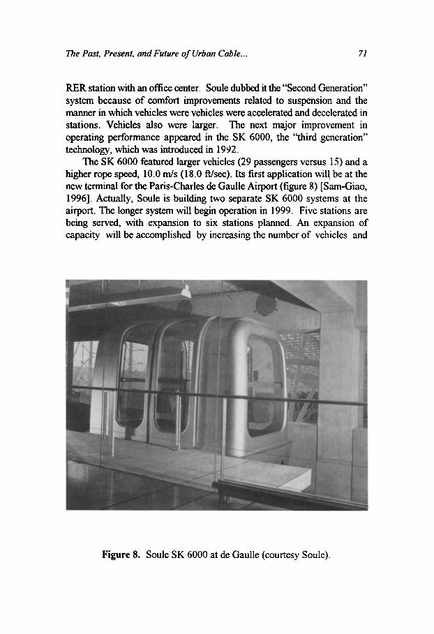
RER station with an office center. Soule dubbed it the “Second Generation” system because of comfort improvements related to suspension and the manner in which vehicles were vehicles were accelerated and decelerated in stations. Vehicles also were larger. The next major improvement in operating performance appeared in the SK 6000, the ‘‘third generation” technology, which was introduced in 1932.
The SK 6000 featured larger vehicles (29 passengers versus 15) and a higher rope speed, 10.0 d s (18.0 Wsec). Its first application will be at the new terminal for the Paris-Charles de Gaulle Airport (figure 8) [Sam-Giao, 19961. Actually, Soule is building two separate SK 6000 systems at the airport. The longer system will begin operation in 1999. Five stations are being served, with expansion to six stations planned. An expansion of capacity will be accomplished by increasing the number of vehicles and
Figure 8. Soule SK 6000 at de Gaulle (courtesy Soule)

72 Edward S. Neumann
reducing the headway. The second system will serve three stations; eventually it will be extended to serve four or five stations.
POMA 2000 and TMSSE. POMA has a history of designing and manufacturing ski area systems, including many detachable gondola systems, pulsed gondola systems, funiculars, aerial tramways, and chairlifts. The firm has ventured into the urban transportation market with both bottom-supported and suspended vehicle technologies. One suspended vehicle system constructed in North America featured standard ski-area detachable gondola technology, modified slightly to meet the requirements of wheelchair bound passengers. The bottom-supported vehicle technology was designed specifically for urban markets. Named the POMA 2000, the technology later was adapted for suspended vehicles under the name TRASSE. POMA’s one North American experience with a conventional detachable gondola in an urban setting will be discussed first, however.
POMA constructed a detachable gondola near downtown New Orleans for the 1984 Louisiana World Exposition [Bunch, 19851. The system spanned the Mississippi River and connected a neighborhood featuring remote parking with the downtown. Intended to relieve congestion on roads and bridges created by visitors to the fair, visitors could park on the west side of the river and take the system to the downtown area near the fair. It was planned to remain in use to serve commuters after the fair ended, hnctioning as part of the public transportation system. But it operated for only a short period after the fair, because of low ridership. The low patronage was partly due to the lack of integration of the gondola with other surface modes. New Orleans was the only city in North America to experiment with use of a detachable gondola as a means of public transportation. Though detachable gondola technology has been studied and recommended as the alternative of choice in studies conducted for Denver, CO; Cincinnati, OH; Kansas City, MO; and Santa Cruz, CA, no other detachable gondola system has been constructed for public transportation use in North America [Neumann, 19901.
Development of POMA’s bottom-supported system, the POMA 2000, was begun in 1972, in association with Creusot-Loire Enterprises of France [Neumann, 19901 [Tarasoff, 1996al. A test track was opened in Grenoble in 1975, and a contract to begin construction of the first urban application was signed in Laon, France in 198 1 to connect the historic government and cultural center of the city with an industrial center and rail station. The Laon system began operation in 1989, and was integrated with the existing public transportation network (figure 9). It serves three stations. Unlike the Soule

The Past, Present, and Future of Urban Cable ... 73
SKY however, the POMA 2000 requires that each adjacent pair of stations be served by a separate loop of cable. Vehicles are transferred between loops of cable at the stations. During this period of transfer, vehicles come to a stop in the station before being accelerated and attached to the next loop of cable. In order to prevent a bunching of the vehicles in the station, cable loops can be run at different relative speeds, so that the travel time between pairs of stations is the same, even though pairs of stations may not be spaced equal distances apart. Vehicles are supported by four pneumatic tires which ride on L-shaped rails. For guidance, eight smaller pneumatic tires are mounted horizontally and bear against the vertical inside surface of the L- shaped rails.
Figure 9. POMA 2000 at Laon (courtesy POMA).
POMA also developed a concept for a detachable suspended vehicle that mirrors the POMA 2000. Named the TRASSE, the system was designed for alignments with limited right-of-way, such as along roadways, or environments where the terrain is not suitable for a rigid guideway [Tarasoff, 1996bl. Vehicle support is provided by two fixed locked-coil

74 Edward S. Neumann
parallel track ropes; a third flexible haul rope provides propulsion. Spans as long as 150 m (492 ft) are envisioned. Vehicles hold 50 passengers, and trains of 2 or 3 w s can be operated. Operating speeds of 7 m/s (23 Wsec) are proposed. At headways of 1 to 3 minutes, capacities of between 2,000 and 3,000 passengers per hour per direction are feasible, and movement of as many as 5,000 passengers may be possible. To date, this version of the POMA 2000 technology has not been demonstrated.
POMA-Otis. In 1996, POMA and Otis combined engineering and business expertise to develop and market cable propelled systems for urban areas. Though not a merger, the two firms are combining the technologies each developed. The first example of the joint approach will be constructed at Zurich's international airport. The technology will represent a marriage ofthe Otis Hovair suspension and the POMA 2000 detachable vehicle. Upon entering a terminal station, the trains will be detached from the between- terminal haul rope and reattached to a cable loop that serves just the terminal. After passengers leave a vehicle, it will move around a tight loop in the station to the boarding area. The alignment will feature two 45 degree curves, the smallest having a radius of 61 m (200 ft). The system will be located in a tunnel, and is scheduled to begin operation in 2002.
Doppefmuyr CABLELiner. The Austrian firm of Doppelmayr has had many years of experience designing and manufacturing ski area systems, including detachable gondolas and detachable chairlifts. Doppelmayr teamed with Siemens, a manufacturer of urban mass transit vehicles, to design and market the bottom-supported CABLE Liner, which appeared in 1996 (figure 10) [Klimmer, 19961. The CABLE Liner features a continuously running loop of cable and detachable vehicles. Vehicle support is provided by two rubber tires that ride on the top of an I-beam. Small horizontal rubber tires press laterally into the I-beams to provide lateral guidance. Like the Soule SK, the Cable Liner vehicles detach from the cable when entering the station, move slowly through the station to allow passengers to load and unload, and re-attach. Alternatively, vehicles can be stopped completely. According to Doppelmayr, target headways are 21.5 s; but if the vehicle comes to a complete stop in a station, headways are 35 s. Operating speed is 8 m/s (26.2 ft/sec) if distances between stops are long, and 6 m / s (19.7 ft/sec) if they are short. Target capacities are 3000 passengers per hour per direction if the vehicles come to a complete stop in stations, and 5000 passengers per hour per direction if the vehicles move slowly through the stations. Maximum line length is 5,000 m (16,368 ft). Vehicles carry 33 passengers and are turned around by turntables at each end of the alignment.Gradients

The Past, Present, and Future of Urban Cable ... 75
Figure 10. DoppelmaydSiemens CABLE Liner (courtesy Doppelmayr).
of up to 15% can be negotiated, and the standard radius curve is 45.8 m ( 150 ft) at a maximum velocity (8 d s ) and a superelevation of 5%. Minimum radius of curvature is 30.6 m (100.4 ft) with a required superelevation of 10%. The sum of the angles of deflection for all horizontal curves can be up to 270 degrees. A 200 m (656 ft) test track is operating at Wolfurt, Austria.
The CABLE Liner also can be designed to operate in a shuttle mode. The guideway and vehicle design are similar to the continuous version, but the system lacks the capability to detach and reattach vehicles to the haul rope. A contract has been signed to build the shuttle version of the system in Las Vegas, NV, to connect the new Mandalay Bay resort complex with the Luxor and Excalibur resorts. The expected opening date is April, 1999. Two independent systems will share common towers along the guideway. One system will serve only the two end terminals to provide express service, and the other will serve the end stations as well as two intermediate stations. The smallest radius of curvature is 90 m (295 fi). Plans also are under

76 Edwurd S. Neumann
development to install a 2830 m (9285 ft) 8-station system in the Donau City complex in Vienna.
Leitner People Mover. Leitner, an Italian firm, also has been a traditional manufacturer of gondola systems for ski areas and recreational areas, as well as urban hniculars and inclines. In 1993, Leitner introduced a bottom-supported detachable technology that is similar to Doppelmayr’s (figure 11) [Urbani, 19981. The test track was constructed at Sterzing, Italy. Leitner reports that the technology is capable of vehicle headways of one minute, and vehicle capacities can range from 20 to 80 passengers. Capacity in terms of passengers per hour per direction can vary from 1,000 to 6,000. Alignment lengths can be up to 6,000 m (19,686 ft), minimum horizontal radius of curvature can be 30 m (98.4 ft), maximum gradient can be 15%, and rope velocity can vary from 6 m / s to 8 m / s ( 19.7 to 26.4 Wsec). Vehicles are supported by plastic tires mounted vertically, which travel
Figure 11. Leitner People Mover (courtesy Leitner)

The Past, Present, and Future of Urban Cable ... 77
on the top flanges of vertical I-beams. Lateral guidance is accomplished by small wheels mounted horizontally below the vehicle. Leitner employs the same technology for the detachable grip and the acceleration and deceleration of vehicles that it uses for its gondola systems.
Leitner has been awarded a contract to construct its People Mover in Perugia, Italy. The first section will feature seven stations. It will connect the suburbs of Monteluce and Pian di Massiano and pass through the historic town center. The final system will have eleven stations. Completion is estimated to be in June, 2001.
Mitsubishi Skyrail. The Skyrail design features gondola-sized vehicles that are suspended beneath a rigid guideway [Takiyosui, 19981. The guideway consists of two I beams joined together at the bottom flanges, but open at the top flanges. The moving haul rope is located between the two vertical webs of the I beams. Vehicles are suspended from a truck that features small wheels which run on the upper outside surfaces of the bottom flanges of the I-beams. Vehicles are detached and reattached to the haul rope in stations. However, the Skyrail is unique in that it utilizes LIMs to accelerate and decelerate the vehicles, rather than the conventional tire and belt technology employed in ski area detachable systems. Because the guideway is rigid, horizontal curves with a radius as low as 30 m (98.4 A) are reported to be feasible. Gradients up to 27% also are reported to be feasible. At claimed headways as low as 38 sec, and car capacities of 25 passengers, line capacities of 2400 passengers per hour per direction could be achieved in theory. The technology has been installed in Hiroshima. Opening in 1998, the system connects the Sen0 railway station on the JR Sanyo Line with a 2,500 unit housing development. The system overcomes a 190 m (623 ft) change in elevation.
The Future
Cable-propelled APM technologies appear to be moving toward the long recognized goal of the APM industry to produce a system that is low-cost, highly reliable, and suited for short to medium distance applications [Dommen, 19931. Whereas only two firms were marketing an urban cable technology in 1982, there presently are eight firms and one consortia. In 1982, no firm was marketing a detachable bottom-supported vehicle; today there are five different continuous systems that transportation planners can chose from. With the increase in the number of technologies available have come improvements in guideway appearance and design, increased haul rope

78 Edward S. Neumann
speed, improved ability to negotiate small radius horizontal curves, and a wider range of vehicle and TU passenger capacities.
It is difficult to establish the oosts of cable technology per meter or ft, or to compare the costs of cable technology versus technology featuring self- propelled vehicles, except on a site-by-site basis. Generally, for systems of relatively short length and modest capacity, cable technology will be less expensive to construct than technology featuring self-propelled vehicles. Savings could range k e e n 20% and 60% dependmg on the specific requirements of the system and the relative proportion of costs associated with the guideway and mechanical components. Given that the cable propelled vehicles generally weigh less than self-propelled vehicles of equal capacity, guideway costs, in principle, should be lower. Vehicles of equivalent capacity should cost less. Safety features should cost less because the location of vehicles attached to a rope can be determined much more easily than the location of self-propelled vehicles. However, these cost advantages may be muted if there are substantial right-of-way, utility relocation, or station costs.
Since the 198O's, one of the goals of the industry has been to achieve higher rope speeds. But the dynamics of moving rope create performance limitations. Limiting velocities for wire haul ropes appear to be about 10 or 12 m/s (32.8 to 39.4 Wsec). At velocities higher than this, vibrations create problems, and it becomes challenging to design the acceleration and deceleration devices, wheels and guidance devices for the haul rope, and the mechanisms to clamp and unclamp vehicles. This speed limitation constrains the feasible length of cable systems, since in-vehicle trip times can become long. The force required to accelerate and decelerate extremely long cables, and the forces which must be withstood by the sheaves and rollers necessary to achieve curves can become limiting also. Systems featuring self-propelled vehicles can offer a level of service advantage for longer trips since higher velocities can be achieved. However, the serpentine belt technology developed by Yantrak may facilitate significantly higher operating speeds than can be achieved by wire rope, and narrow the performance gap between cable and self-propelled vehicle systems.
One of the notable advances in cable technology for urban applications has been in the area of weight reduction and aesthetics of the guideway. The steel guideways of the Yantrak, Doppelmayr, Leitner, and Soule systems are substantially less massive and heavy than the guideways of the earlier systems. Techniques for super-elevating vehicles on horizontal curves without having to slope the running surface of the guideway also fosters

The Past, Present, and Future of Urban Cable ... 79
higher speeds without significantly increasing the costs of guideway construction. Several technologies can achieve a minimum radius of horizontal curvature as low as 30m (98.4 ft).
The development of four different technologies featuring bottom- supported detachable vehicles has increased the options available for simultaneously achieving high capacity with short wait times for systems of any given length. However, the strength of the market for detachable systems is not yet established. The detachable system is competing for a market niche that self-propelled vehicle systems have successfdly penetrated. While low capital cost is one of the advantages of cable technology, cable propelled systems featuring detachable vehicles are substantially more costly to construct than the simpler shuttle systems. Maintenance costs also are higher. When conducting an alternatives analysis for a site, the higher speeds available from systems featuring self-propelled vehicles and the potential for self-propelled vehicles to achieve very high capacities may tip the balance in their favor. Never-the-less, it is believed by at least three firms within the cable system industry that a potential market must exist for an urban cable technology featuring bottom-supported detac,hable vehicles. No detachable urban system has been constructed in North America to date. The urban detachable technologies all have been installed in the home countries of the suppliers. It is noted that a system featuring detachable technology is being installed in the U.S. in a reversible configuration rather than a detachable configuration. At the same time, pulsed systems have not been explored, even though they may offer a good, cost-effective compromise between reversible and continuous service in certain situations meumann, 19961.
The potential applications for urban cable technology are, in theory, numerous. Many involve internal site circulation. Besides applications in smaller airports, cable systems could connect rail transit terminals with parking areas or office centers and serve as feeders to line-haul transit. Small systems could connect garages or parking areas with employment or shopping centers, or serve internal circulation needs within resorts, industrial parks, commercial centers or any land development for which it is desirable to minimize internal penetration by autos [Warren, 19971.
A final observation concerns the likely fbture for suspended-vehicle systems, in contrast to bottom-supported systems. There has been a lack of construction of new suspended systems during the past twenty years, even though a relatively large number of bottom-supported systems have been built. Despite their low capital cost, faster construction, and nearly off-the-

80 Edward S. Neumann
shelf availability, suspended detachable systems (i.e., gondolas) do not appear to be able to penetrate the urban market in North America, despite their prevalence at ski areas. In part, this may be due to a fear people have of riding in a vehicle suspended from a wire rope. There is a widespread lack of familiarity with gondola systems, since only a small percentage of the population skis. Elected officials and transportation planners may feel that the public will not accept them as readily as bottom-supported systems. If experience to date can serve as a reliable guide, the potential for suspended systems does not appear to be nearly as great as the potential for bottom- supported systems. This implies that a market for the types of suspended systems that are wellestablished on the ski slopes may not yet exist for the urban environments of North America.
References
Bunch, J. K.; Fletcher, J.; Bonasso, S. 1985. “Application of a Detachable Gondola Ropeway in an Urban Transport Environment: New Orleans, LA” in Automated People Movers - Engineering and Management in Major Activity Centers, (Proceedings of the First International Conference on Automated People Movers, E. S. Neumann, and M. V. A. Bondada, editors) American Society of Civil Engineers, New York, pp. 442-45 1 .
Dommen, Willy, 1993. “A Marketing Analysis of an Old Concept: the Horizontal Elevator-Monorail” in Automated People Movers IV, (Proceedings of the Fourth International Conference on Automated People Movers, W. J. Sproule, E. S. Neumann, and M. V. A. Bondada, editors) American Society of Civil Engineers, New York, pp. 60-76.
Frenkiel, Z., 1966. Aerial Tramways and Funicular Railways, Pergamon Press, Warsaw.
Hilton, G. W. , 1982. The Cable Car in America, Howell North Books, San Diego.
Huard, J. P.; Cote, A,, 1996. “Cable Driven Automatic Shuttles” APM96 (Proceedings of the 5* International Conference on Automated People Movers) afcet, Paris, France, pp. 739-748.
Klimmer, A., 1996. “The CABLE Liner: The APM System of the Future”, APM96 (Proceedings of the 5”’ International Conference on Automated People Movers) afcet, Paris, France, pp. 55 1-562.

The Past, Present, and Future of Urban Cable ... 81
Kunczynski, Y ., 1997. “New Propulsion for Cost-Effective Shuttle” Elevator World, December, pp. 88-92.
Neumann, E. S.; Jordon, P., 1989. “Experience of the Roosevelt Island Tramway - An Urban Aerial Cable People Mover” Automate People Movers II (Proceedings of the Second International Conference on Automated People Movers, M. V. A. Bondada, W. S. Sproule, and E. S. Neumann, editors) American Society of Civil Engineers, New York,
Neumann, E. S. , 1990. Planner s Guide to Cable-Propelled People Mover Systems for Urban Activity Centers, Mid-Atlantic Universities Transportation Center.
Neumann, E. S., 1996. “Comparing Level of Service Between Shuttle and Pulsed Cable Propelled People Mover Technology” APM96 (Proceedings of the 5“ International Conference on Automated People Movers) afcet, Paris, France, pp. 537-546.
Neumann, E. S., 1998. “Small Scale Systems in Las Vegas: Appropriate Technology for the Setting” Automated People Movers P7 (Proceedings of the Sixth International Conference on Automated People Movers, W. J. Sproule, E. S. Neumann, and S. W. Lynch, editors) American Society of Civil Engineers, Washington, DC, pp. 272-283.
Sam-Giao, D; Gardere, C., 1996. “The SK Automated People Mover for Charles de Gaulle Airport: Towards an Innovative Transportation System” APM96 (Proceedings of the 5* International Conference on Automated People Movers) afcet, Paris, France, pp. 107-1 16.
Tarasoff, S.; Lemarie, X., 1996a. “Experience with the System in Operation - The Laon Poma 2000” APM96 (Proceedings of the 5* International Conference on Automated People Movers) afcet, Paris, France, pp. 729-738.
Tarasoff, S., 1996b. “The TRASSE System - Automatic Transportation on an Economical Site” APM96 (Proceedings of the S” International Conference on Automated People Movers) afcet, Paris, France, pp.
Takiyosu, K; Shirakiharu, T., 1998. “Hiroshima’s Short-Distance Transit System: Skyrail” Automated People Movers VI (Proceedings of the Sixth International Conference on Automated People Movers, W. J. Sproule, E. S. Neumann, and S. W. Lynch, editors) American Society of Civil Engineers, Washington, DC, pp. 297-304.
Urbani, E.; Dal Pos, F; Conte, G., 1998. “Cable Driven Automatic Systems for Urban Applications” Automated People Movers VI (Proceedings of
pp. 909-918.
677-684.

82 Edward S. Neumann
the Sixth International Conference on Automated People Movers, W. J. Sproule, E. S. Neumann, and S. W. Lynch, editors) American Society of Civil Engineers, Washington, DC, pp. 253-261.
Venter, M. S.; Puglisi, T. C., 1996. “Experiences with the Planning and Implementation of the Automated People Mover System at the CincinnatUNorthern Ky Internatid Airport” MA496 (Proceedings of the 5”’ International Conference on Automated People Movers) afcet,
Warren, Roxanne, 1997. The Urban Oasis: Guideways and Greenways in Paris, FWM, pp. 97-106.
the Human Environment, McGraw Hill.