past, present and future of ieee 802.11 toward wireless ......past, present and future of ieee...
TRANSCRIPT

Past, Present and Future of IEEE 802.11 toward Wireless Gigabit Experience
Periklis Chatzimisios, PhD, Alexander TEI of Thessaloniki, GreeceAthanassios Iossifides, PhD, Alexander TEI of Thessaloniki, GreeceJesus Alonso‐Zarate, PhD, CTTC, Barcelona, Spain
December 2014IEEE Globecom 2014, Austin, Texas, US
1 Introduction to IEEE 802.11 family
2 IEEE 802.11ac, VHT below 6GHz
3New Emerging Amendments4Challenges and Open Issues5
IEEE 802.11ad, DMG @60GHz

page 3© 2014 P. Chatzimisios, A. Iossifides, J. Alonso‐Zarate
Introduction to 802.11 family1.1 The Standard for Wireless Local Area Networks (WLAN)1.2 History of specifications1.3 The PHY and MAC specifications
page 4© 2014 P. Chatzimisios, A. Iossifides, J. Alonso‐Zarate
Introduction to 802.11 family1.1 The Standard for Wireless Local Area
Networks (WLAN)1.2 History of specifications1.3 The PHY and MAC specifications
page 5© 2014 P. Chatzimisios, A. Iossifides, J. Alonso‐Zarate
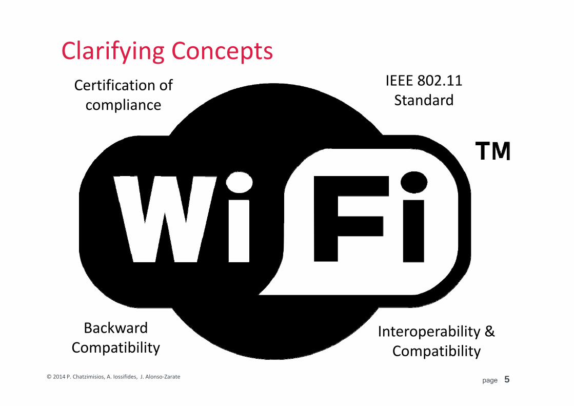
Clarifying Concepts
Interoperability & Compatibility
BackwardCompatibility
Certification of compliance
IEEE 802.11Standard

page 6© 2014 P. Chatzimisios, A. Iossifides, J. Alonso‐Zarate
WiFi is everywhere
Source: https://www.qualcomm.com/media/documents/files/wireless-networks-wi-fi-evolution.pdf
page 7© 2014 P. Chatzimisios, A. Iossifides, J. Alonso‐Zarate
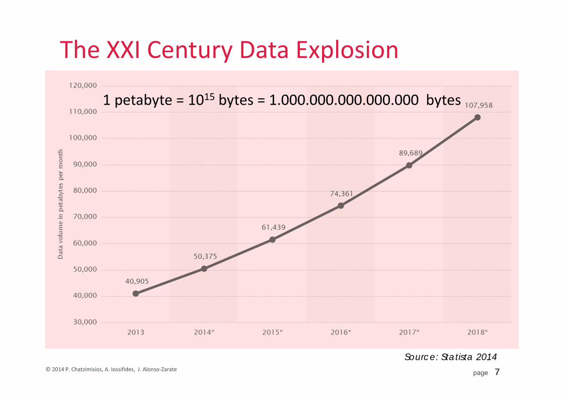
The XXI Century Data Explosion
Source: Statista 2014
1 petabyte = 1015 bytes = 1.000.000.000.000.000 bytes
page 8© 2014 P. Chatzimisios, A. Iossifides, J. Alonso‐Zarate
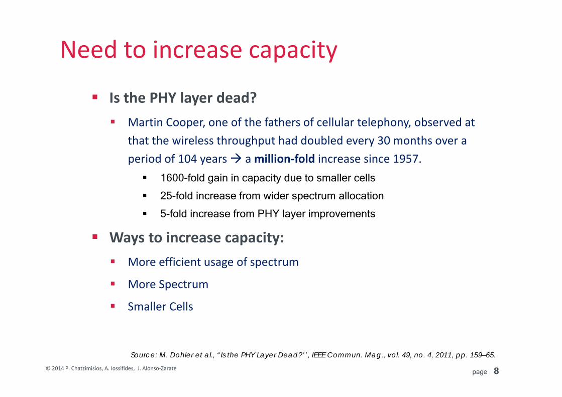
Source: M. Dohler et al., “Is the PHY Layer Dead?’’, IEEE Commun. Mag., vol. 49, no. 4, 2011, pp. 159–65.
Need to increase capacity
Is the PHY layer dead? Martin Cooper, one of the fathers of cellular telephony, observed at
that the wireless throughput had doubled every 30 months over a period of 104 years a million‐fold increase since 1957. 1600-fold gain in capacity due to smaller cells
25-fold increase from wider spectrum allocation
5-fold increase from PHY layer improvements
Ways to increase capacity: More efficient usage of spectrum
More Spectrum
Smaller Cells

page 9© 2014 P. Chatzimisios, A. Iossifides, J. Alonso‐Zarate
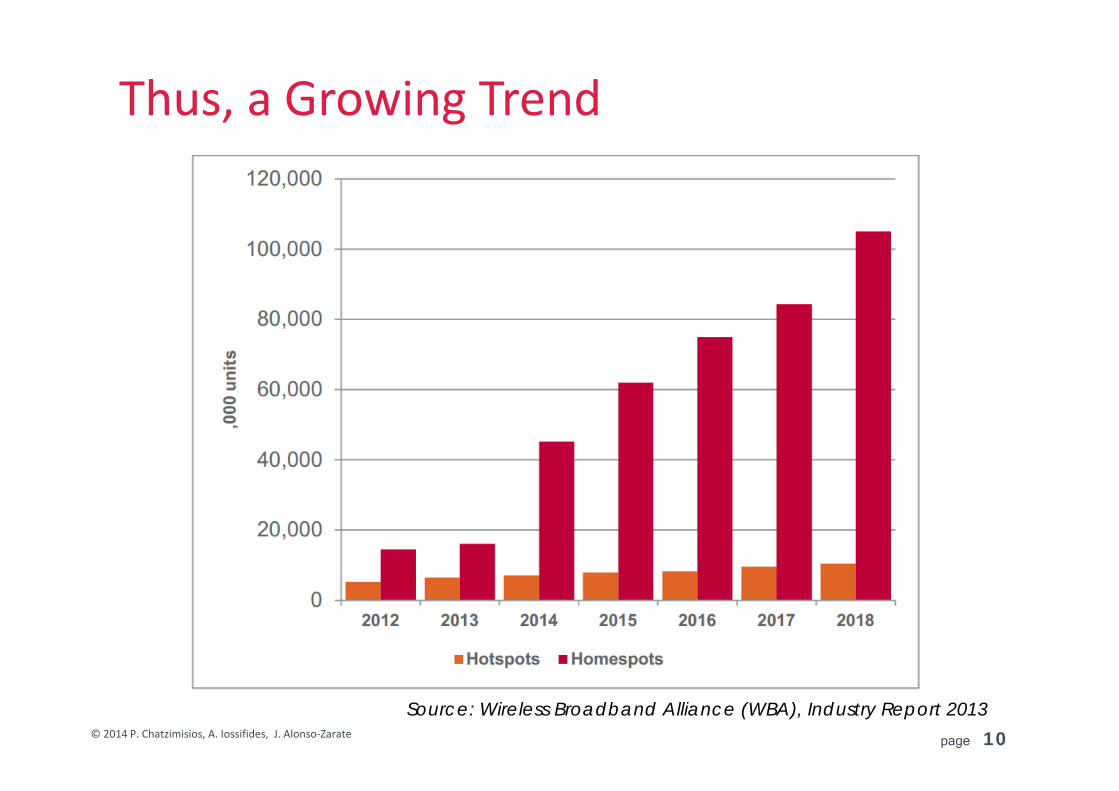
Source: Wireless Broadband Alliance (WBA), Industry Report 2013
WiFi will be part of the integral solution
page 10© 2014 P. Chatzimisios, A. Iossifides, J. Alonso‐Zarate
Source: Wireless Broadband Alliance (WBA), Industry Report 2013
Thus, a Growing Trend

WIFI
Bluetooth LE
Data Transmission Rate ( Delay! Energy! Reliability! … !)
10m 100m 1km 10km
Kbps
bps
Mbps
Gbps
RFID
Zigbee
2G, 3G, 3G+
LTE, LTE‐A, beyond
LPWA‐M2M
mWave
Wireless Technologies (selected)

Reliability
Availability
Zigbee‐like
Bluetooth LE
WIFI – 802.11 Standards
Proprietary Cellular
Standardized Cellular
Wired Networks
Availability = coverage, roaming, mobility, critical mass in rollout, etc.Reliability = resilience to interference, throughput guarantees, low outages, etc.(Total Cost of Ownership = CAPEX, OPEX.)
Positioning of WiFi

Ubiquitous Infrastructure Vibrant Standard
Low Cost Sound Security
300 members
WPA2/PSK/TLS/SSL
Source: Wireless Broadband Access (WBA), Informa, Nov. 2011
Some KEY advantages of WIFI

Crowded ISM Band Limited Power
Lack of Network Planning
WPA2/PSK/TLS/SSL
Some limitations of WIFI
Still using CSMA!!!

Growing WIFI ecosystem…

page 16© 2014 P. Chatzimisios, A. Iossifides, J. Alonso‐Zarate
Introduction to 802.11 family1.1 The Standard for Wireless Local Area Networks (WLAN)
1.2 History of specifications1.3 The PHY and MAC specifications

page 17© 2014 P. Chatzimisios, A. Iossifides, J. Alonso‐Zarate
Standards: Definition
Standards are published documents that establishspecifications and procedures designed to maximize thereliability of the materials, products, methods, and/orservices people use every day. Standards address a range ofissues, including but not limited to various protocols to helpmaximize product functionality and compatibility, facilitateinteroperability and support consumer safety and publichealth (definition by IEEE‐SA)
Can be International/European/National
page 18© 2014 P. Chatzimisios, A. Iossifides, J. Alonso‐Zarate
Standards: Motivation
Market Demand
Essential for the long term deployment of technology
Interoperability
Roaming worldwide
Japan
USAChina
Korea

page 19© 2014 P. Chatzimisios, A. Iossifides, J. Alonso‐Zarate
Standards within IEEEIEEE Standards Association (IEEE‐SA) Encourages & coordinates the development process of IEEE standards
IEEE Comm. Society Standards Development Board (COM/SDB) Sponsors standards in communications & networking
page 20© 2014 P. Chatzimisios, A. Iossifides, J. Alonso‐Zarate
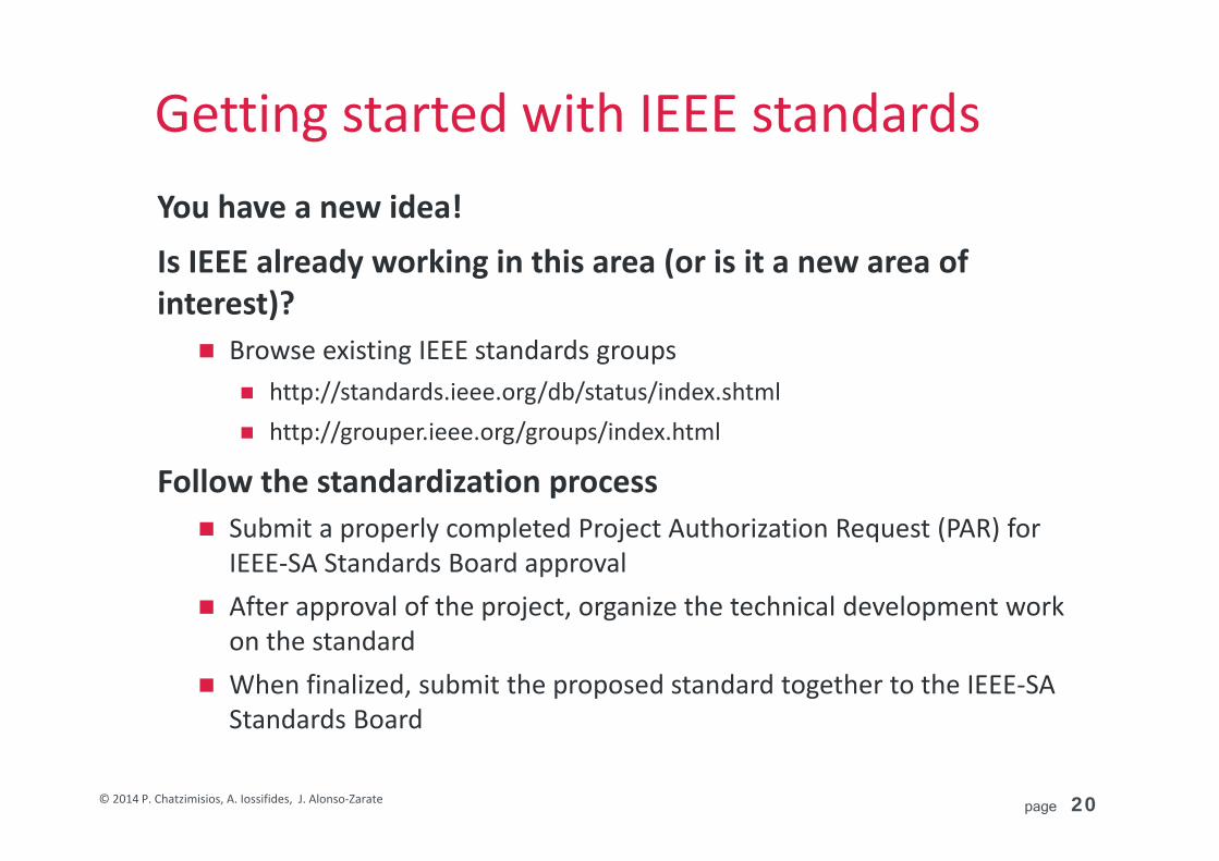
Getting started with IEEE standards You have a new idea!
Is IEEE already working in this area (or is it a new area of interest)? Browse existing IEEE standards groups
http://standards.ieee.org/db/status/index.shtml http://grouper.ieee.org/groups/index.html
Follow the standardization process Submit a properly completed Project Authorization Request (PAR) for
IEEE‐SA Standards Board approval After approval of the project, organize the technical development work
on the standard When finalized, submit the proposed standard together to the IEEE‐SA
Standards Board

page 21© 2014 P. Chatzimisios, A. Iossifides, J. Alonso‐Zarate
Standardization process
Conclusion: It is a very long and complicated process!
Idea!
ProjectApprovalProcess
DevelopDraft
Standards(in
WorkingGroups)
SponsorBallot
IEEE‐SAStandardsBoard
ApprovalProcess
PublishStandards
Revise Standard
Archive Withdrawn Standard
Maximum of 4 years
Maximum of 10 years
page 22© 2014 P. Chatzimisios, A. Iossifides, J. Alonso‐Zarate
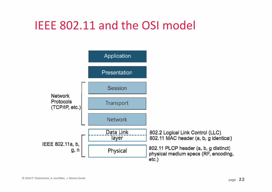
IEEE 802.11 and the OSI model

page 23© 2014 P. Chatzimisios, A. Iossifides, J. Alonso‐Zarate
Key IEEE 802.11 Amendments
1997 1998 1999 2000 2001 2002 2003 2004 2005 2006 2007 2008 2009 2010 2011 2012 2013
• 802.11a• Data rate: 54 Mbps• Frequency band: 5 GHz• PHY: OFDM• Use case: Internet
• 802.11b• Data rate: 11 Mbps• Frequency band: 2.4 GHz• PHY: DSSS with CCK WEP• Use case: Email
• 802.11g• Data rate: 54 Mbps• Frequency band: 2.4 GHz• PHY: OFDM• Wi‐Fi starts to become ubiquitous • Use case: Rich‐data Web experience
• 802.11n • Data rate: Up to 600 Mbps• Frequency band: 2.4 GHz & 5 GHz• PHY: OFDM/MIMO• Higher throughput• Enhanced range due to use of MIMO• Use case: Medium‐resolution video
streaming
• 802.11ac• Data rate: Up to 7 Gbps(first solutions on market < 1.8 Gbps)• Frequency band: 5 GHz• PHY: OFDM/MIMO• 8 parallel streams • Use case: Coverage for video “Wired”
Compliment
• 802.11ad• Data rate: Up to 7 Gbps• Frequency band: 60 GHz• PHY: OFDM/MIMO• Tri‐band Wi‐Fi• Use case: short‐range app
1st Generation
5th Generation
5th Generation
4th Generation
3rd Generation
2nd Generation
Source: D. Gajic, K. Ntontin, R. Palacios, “802.11n and Beyond: and Overview”, GREENET Project Presentation, July 2013
page 24© 2014 P. Chatzimisios, A. Iossifides, J. Alonso‐Zarate
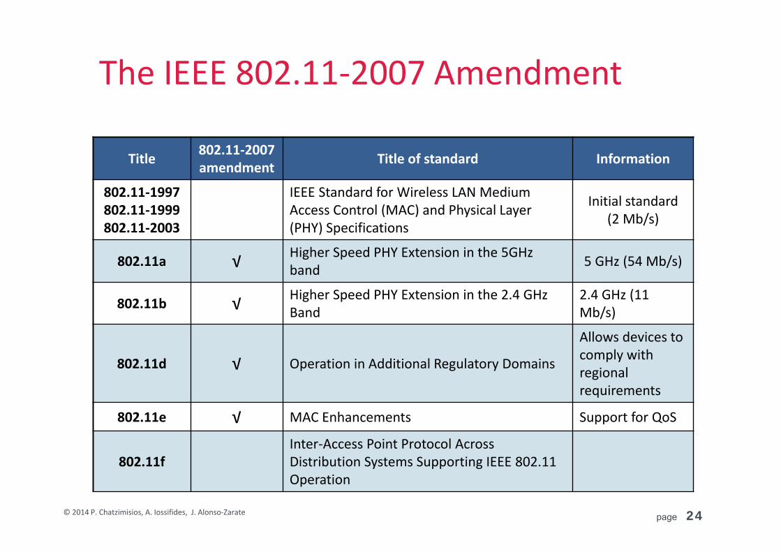
The IEEE 802.11‐2007 Amendment
Title 802.11‐2007 amendment Title of standard Information
802.11‐1997802.11‐1999802.11‐2003
IEEE Standard for Wireless LAN Medium Access Control (MAC) and Physical Layer (PHY) Specifications
Initial standard (2 Mb/s)
802.11a √ Higher Speed PHY Extension in the 5GHz band 5 GHz (54 Mb/s)
802.11b √ Higher Speed PHY Extension in the 2.4 GHz Band
2.4 GHz (11 Mb/s)
802.11d √ Operation in Additional Regulatory Domains
Allows devices to comply with regional requirements
802.11e √ MAC Enhancements Support for QoS
802.11fInter‐Access Point Protocol Across Distribution Systems Supporting IEEE 802.11 Operation

page 25© 2014 P. Chatzimisios, A. Iossifides, J. Alonso‐Zarate
Title 802.11‐2007 amendment Title of standard Information
802.11g √ Higher Data Rate Extension in the 2.4 GHz Band 2.4 GHz (54 Mb/s)
802.11h √Spectrum and Transmit Power Management Extensions in the 5 GHz Band in Europe
In Europe 5 GHz devices implement 802.11h
802.11i √ MAC Security Enhancements WPA and WPA2
802.11j √ 4.9 GHz–5 GHz Operation in Japan
Compliance with Japanese 5 GHz spectrum regulation
802.11ma 802.11 Standard Maintenance & Revision ‐
802.11t Recommended Practice for the Evaluation of 802.11 Wireless Performance ‐
The IEEE 802.11‐2007 Amendment

page 26© 2014 P. Chatzimisios, A. Iossifides, J. Alonso‐Zarate
Title 802.11‐2012 amendment Title of standard Information
802.11‐2007IEEE Standard for Wireless LAN Medium Access Control (MAC) and Physical Layer (PHY) Specifications
Supersedes 802.11‐1999 and incorporates amendments a, b, d, e, & g–j
802.11‐2012 802.11 Accumulated Maintenance Changes
Supersedes 802.11‐2007 and incorporates amendments k, n, r, y, p, s, u, w, v & z
802.11c Media Access Control (MAC) Bridges
802.11k √ Radio Resource Measurement Measurements of the wirelesschannel
802.11n √ Enhancements for Higher Throughput 2.4 GHz and 5 GHz (600Mb/s)
802.11r √ Fast Roaming Fast hand‐off for moving devices
802.11y √ 3650–3700 MHz Operation in USA
The IEEE 802.11‐2012 Amendment

page 27© 2014 P. Chatzimisios, A. Iossifides, J. Alonso‐Zarate
Title 802.11‐2012 amendment Title of standard Information
802.11mb 802.11 Standard Maintenance & Revision Second maintenance TG
802.11p √ Wireless Access for the Vehicular Environment V2V and V2I communication
802.11s √ Mesh Networking
802.11u √ Interworking with External Networks
Convergence of 802.11 and GSM
802.11w √ Protected Management Frames Security for management frames
802.11v √ Wireless Network Management Management
802.11z √ Extensions to Direct Link Setup (DLS)
The IEEE 802.11‐2012 Amendment

page 28© 2014 P. Chatzimisios, A. Iossifides, J. Alonso‐Zarate
Recently Published Amendments
Title Title of standard Information
802.11aa MAC Enhancements forRobust Audio Video Streaming Video Transport Streams
802.11ac Enhancements for Very HighThroughput for Operation in Bands below 6 GHz
Very High Throughput <6 GHz
802.11ad Enhancements forVery High Throughput in the 60 GHz Band
Very High Throughput 60 GHz
802.11ae Prioritization of Management Frames
802.11af Television White Spaces (TVWS) Operation

page 29© 2014 P. Chatzimisios, A. Iossifides, J. Alonso‐Zarate
Amendments Under Development
Title Title of standard Information
802.11ah Sub 1 GHz sensor network, smart metering
802.11ai Fast Initial Link Setup
802.11aj China Millimeter Wave
802.11ak Enhancements for Transit Links Within Bridged Networks
802.11aq Pre‐association Discovery
802.11ax High Efficiency WLAN
802.11mc Standard maintenance (publishing 802.11‐2015)
802.11‐2015 802.11 Accumulated Maintenance Changes Will supersede 802.11‐2012 & incorporate all amendments
page 30© 2014 P. Chatzimisios, A. Iossifides, J. Alonso‐Zarate
Introduction to 802.11 family1.1 The Standard for Wireless Local Area Networks (WLAN)1.2 History of specifications
1.3 The PHY and MAC specifications

page 31© 2014 P. Chatzimisios, A. Iossifides, J. Alonso‐Zarate
IEEE 802.11 Architecture
Terminology:
Access point (AP)
Wireless station (STA)
Infrastructure mode (BSS)
Ad‐hoc mode (WiFi Direct)
page 32© 2014 P. Chatzimisios, A. Iossifides, J. Alonso‐Zarate
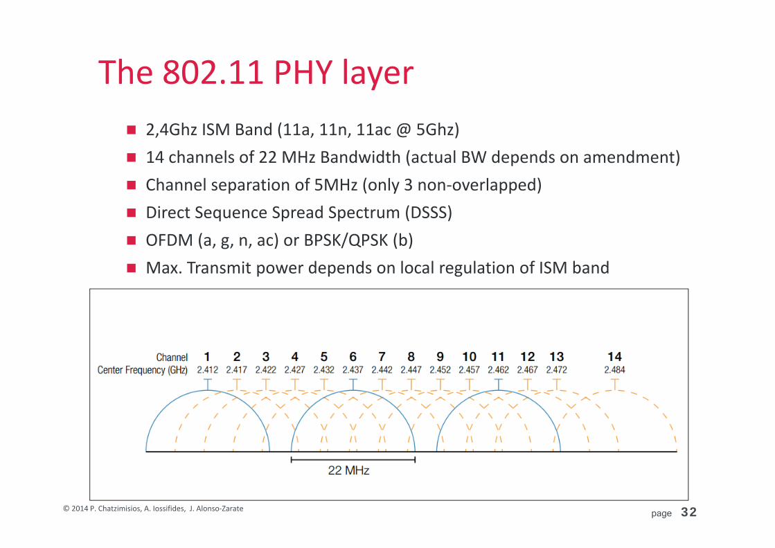
The 802.11 PHY layer 2,4Ghz ISM Band (11a, 11n, 11ac @ 5Ghz) 14 channels of 22 MHz Bandwidth (actual BW depends on amendment) Channel separation of 5MHz (only 3 non‐overlapped) Direct Sequence Spread Spectrum (DSSS) OFDM (a, g, n, ac) or BPSK/QPSK (b) Max. Transmit power depends on local regulation of ISM band

page 33© 2014 P. Chatzimisios, A. Iossifides, J. Alonso‐Zarate
Access Methods in 802.11 MAC Layer DCF (Distributed Coordination Function) Ad hoc and infrastructure mode Contention based distributed system based on CSMA RTS/CTS mechanism (optional) Mandatory access mode
PCF (Point Coordination Function) Infrastructure mode Contention free centralized system Polling to coordinate senders, e.g. to ensure some degree of QoS For real time service SIFS < PIFS < DIFS (priorities!) Optional mechanism

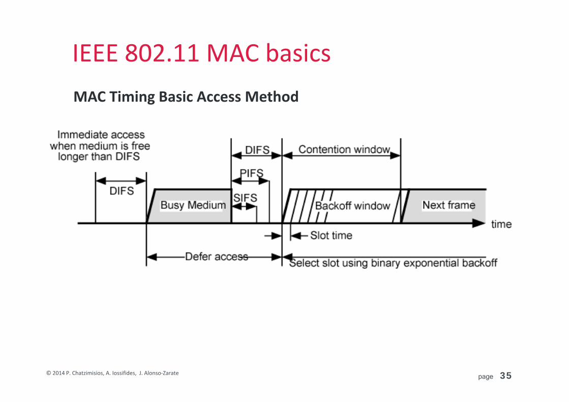
page 34© 2014 P. Chatzimisios, A. Iossifides, J. Alonso‐Zarate
IEEE 802.11 MAC basicsCarrier Sensing Multiple Access (CSMA) + optional CA
+
Binary Exponential Backoff(BEB)
CW = 2k(CWmin+1)‐1
k = the backoff stage (0,…K)
Upon success:
CW = CWmin
page 35© 2014 P. Chatzimisios, A. Iossifides, J. Alonso‐Zarate
IEEE 802.11 MAC basicsMAC Timing Basic Access Method
page 36© 2014 P. Chatzimisios, A. Iossifides, J. Alonso‐Zarate
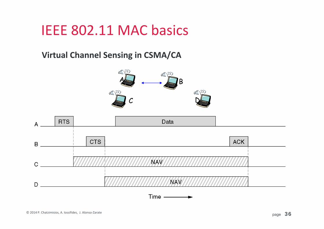
IEEE 802.11 MAC basicsVirtual Channel Sensing in CSMA/CA
A B
C D
page 37© 2014 P. Chatzimisios, A. Iossifides, J. Alonso‐Zarate
Some Well‐Known Problems
Due to CSMA and BEB Large overhead per MAC Protocol Data Unit (MPDU) Lack of QoS guarantees (best effort) Hidden terminal problem Exposed terminal problem Capture effect Congestion under heavy traffic loads (collisions)
Due to Adaptive Rate Anomaly Problem Slowest stations occupy the channel for longer periods
page 38© 2014 P. Chatzimisios, A. Iossifides, J. Alonso‐Zarate
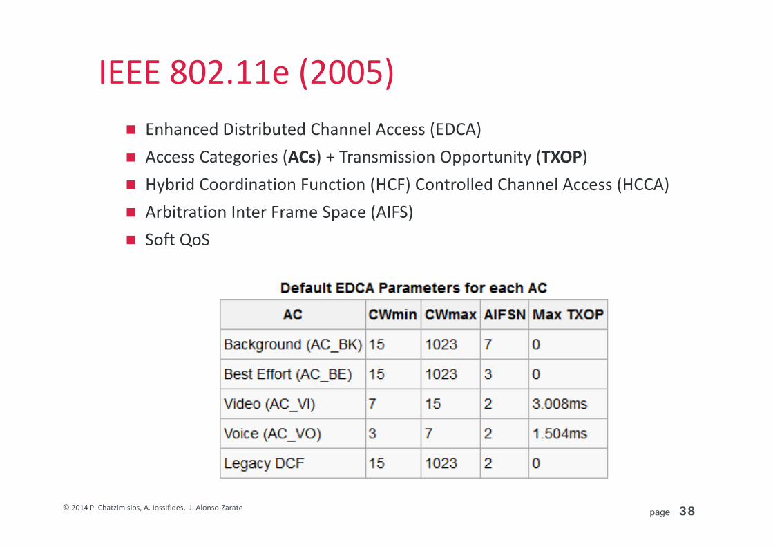
IEEE 802.11e (2005) Enhanced Distributed Channel Access (EDCA) Access Categories (ACs) + Transmission Opportunity (TXOP) Hybrid Coordination Function (HCF) Controlled Channel Access (HCCA) Arbitration Inter Frame Space (AIFS) Soft QoS

page 39© 2014 P. Chatzimisios, A. Iossifides, J. Alonso‐Zarate
IEEE 802.11n (2009)
Both at 2,4GHz and 5GHzUp to 600Mbps Single User MIMO technology + OFDM Solves much better multipath propagationDouble channel bandwidth (20 and 40MHz) Reduction of protocol overhead: MSDU and MPDU Aggregation (also reduces contention) Block Acknowledgement (BACK)
– All packets transmitted within a TXOP Key limitation only one peer‐to‐peer link!
page 40© 2014 P. Chatzimisios, A. Iossifides, J. Alonso‐Zarate
What’s next?
IEEE 802.11ac, VHT below 6GHz
IEEE 802.11ad, DMG at 60GHz

page 41© 2014 P. Chatzimisios, A. Iossifides, J. Alonso‐Zarate
IEEE 802.11ac, VHT below 6 GHz2.1 Key features and use cases2.2 Physical layer description (PHY)2.3 MAC layer description (MAC)

page 42© 2014 P. Chatzimisios, A. Iossifides, J. Alonso‐Zarate
IEEE 802.11ac, VHT below 6 GHz2.1 Key features and use cases2.2 Physical layer description (PHY)2.3 MAC layer description (MAC)

page 43© 2014 P. Chatzimisios, A. Iossifides, J. Alonso‐Zarate
Key featuresHigher bit rates (reaching 6.75 Gbps) over the 5GHz band via More channel bonding, increased from the maximum of 40 MHz in
802.11n, up to 80 or even 160 MHz. Denser modulation, using up to 256QAM (64QAM for 802.11n) More spatial streams through MIMO: Whereas 802.11n stopped at 4
spatial streams, 802.11ac goes all the way to 8. Identified as Very High Throughput (VHT).
MU‐MIMO Allows an AP to send multiple frames to multiple clients
simultaneously (802.11 first) over the same frequency spectrum and PHY frame.
New features in MAC in order to support MU‐MIMO.
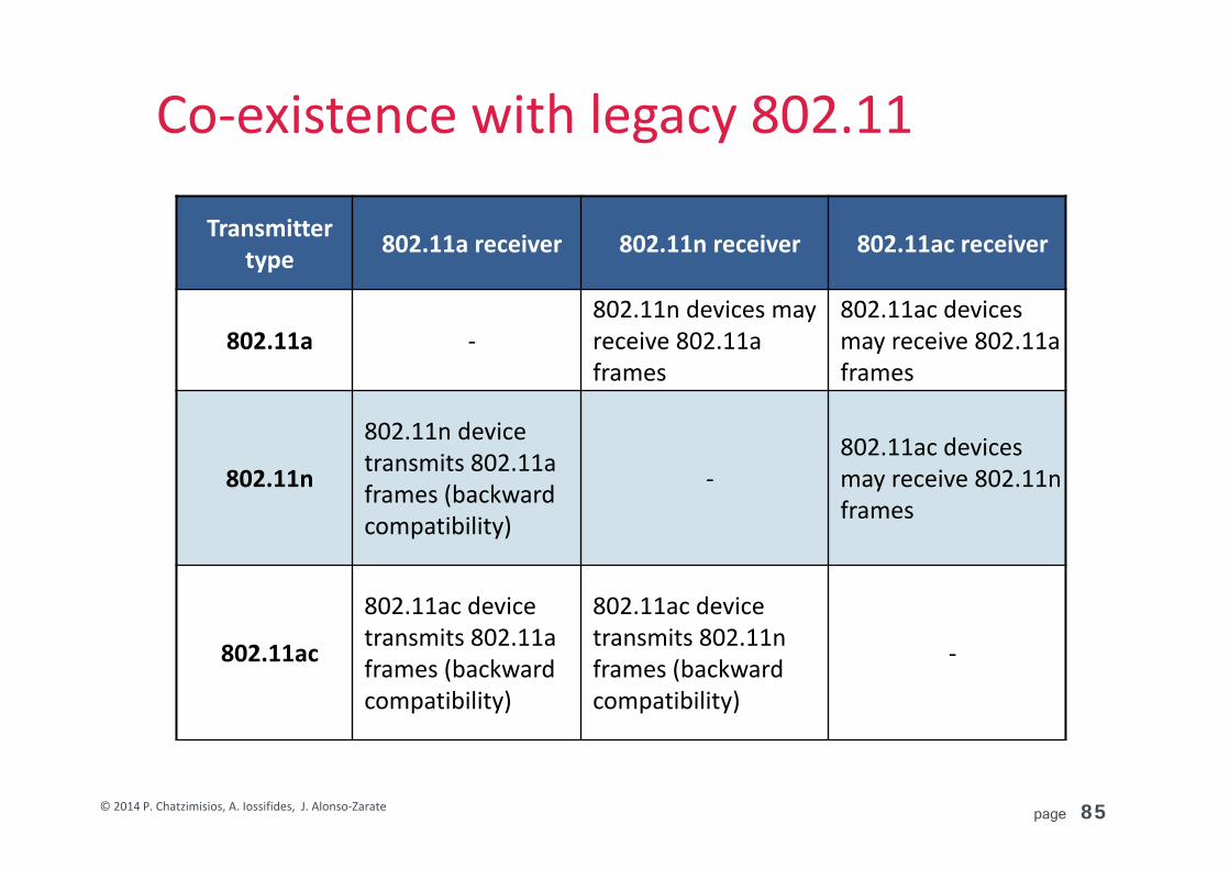
Backwards compatibility and coexistence with 802.11a/n

page 44© 2014 P. Chatzimisios, A. Iossifides, J. Alonso‐Zarate
Use cases
Use cases

page 45© 2014 P. Chatzimisios, A. Iossifides, J. Alonso‐Zarate
IEEE 802.11ac, VHT below 6 GHz2.1 Key features and use cases
2.2 Physical layer description (PHY)2.3 MAC layer description (MAC)
page 46© 2014 P. Chatzimisios, A. Iossifides, J. Alonso‐Zarate
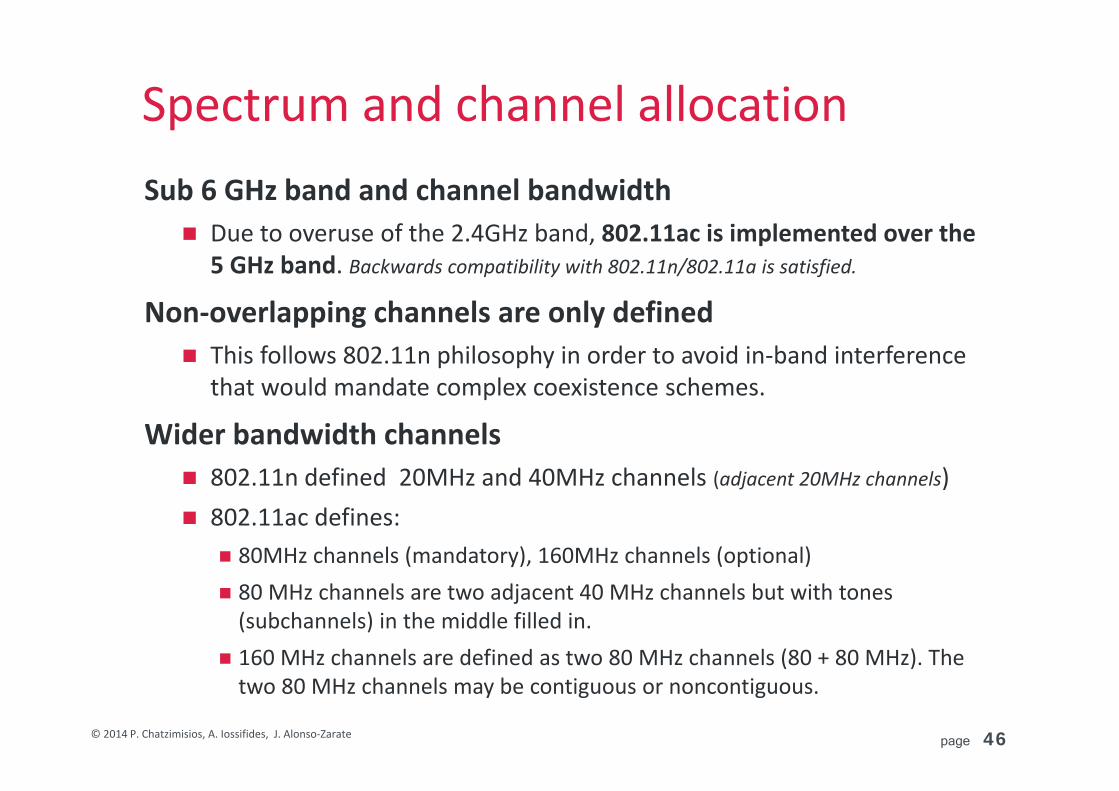
Spectrum and channel allocationSub 6 GHz band and channel bandwidth Due to overuse of the 2.4GHz band, 802.11ac is implemented over the
5 GHz band. Backwards compatibility with 802.11n/802.11a is satisfied.
Non‐overlapping channels are only defined This follows 802.11n philosophy in order to avoid in‐band interference
that would mandate complex coexistence schemes.
Wider bandwidth channels 802.11n defined 20MHz and 40MHz channels (adjacent 20MHz channels) 802.11ac defines:
80MHz channels (mandatory), 160MHz channels (optional) 80 MHz channels are two adjacent 40 MHz channels but with tones (subchannels) in the middle filled in.
160 MHz channels are defined as two 80 MHz channels (80 + 80 MHz). The two 80 MHz channels may be contiguous or noncontiguous.
page 47© 2014 P. Chatzimisios, A. Iossifides, J. Alonso‐Zarate
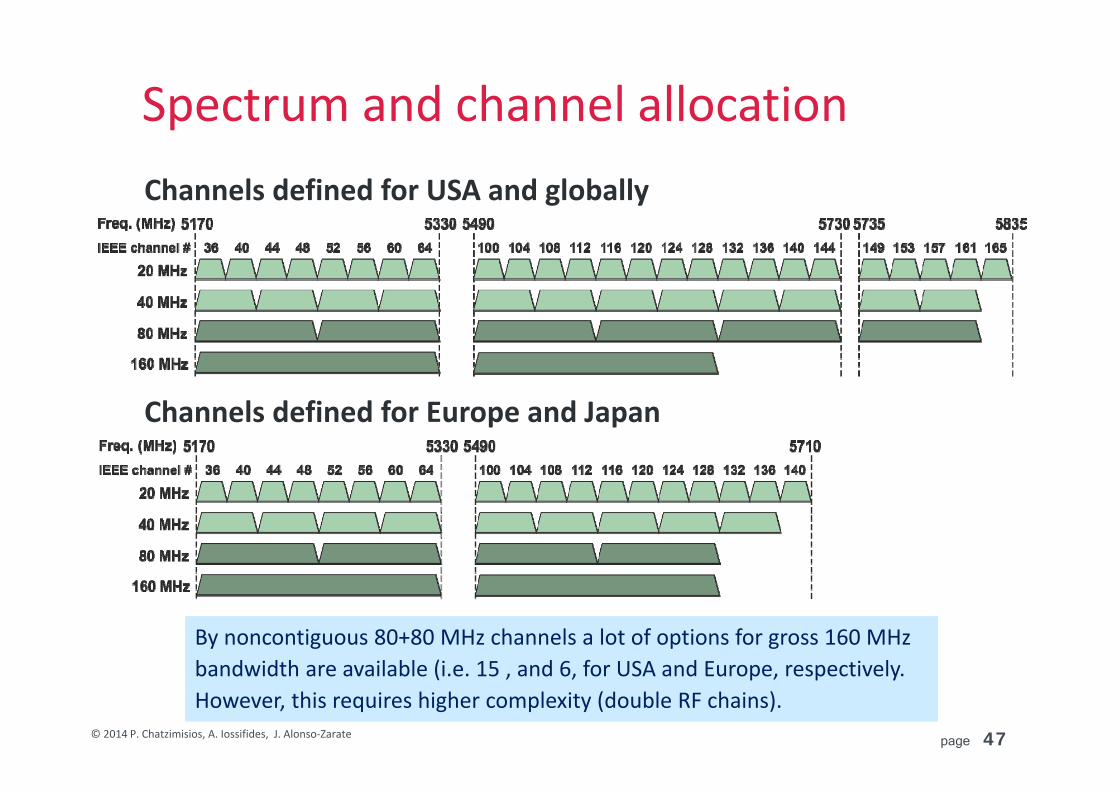
Spectrum and channel allocationChannels defined for USA and globally
Channels defined for Europe and Japan
By noncontiguous 80+80 MHz channels a lot of options for gross 160 MHz bandwidth are available (i.e. 15 , and 6, for USA and Europe, respectively. However, this requires higher complexity (double RF chains).

page 48© 2014 P. Chatzimisios, A. Iossifides, J. Alonso‐Zarate
Spectrum detailsSpectrum mask Total transmission power
depends on regulations FCC determines Max TX EIRP at 23dBm for channels 36‐48, 30dBm for channels 52‐64 and 100‐144, and 36dBm for channels 149‐161.
Channel BW A (MHz) B (MHz) C (MHz) D (MHz)
20 MHz 9 11 20 30
40 MHz 19 21 40 60
80 MHz 39 41 80 120
160 MHz 79 81 160 240
page 49© 2014 P. Chatzimisios, A. Iossifides, J. Alonso‐Zarate
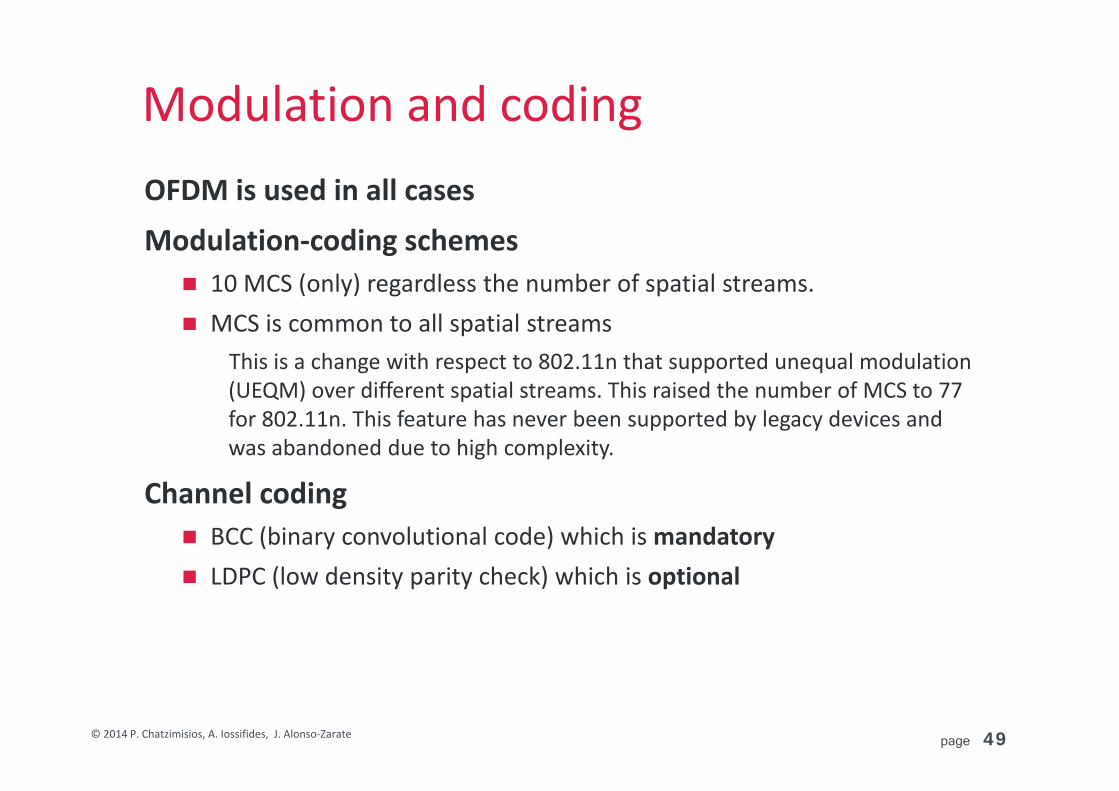
Modulation and codingOFDM is used in all cases
Modulation‐coding schemes 10 MCS (only) regardless the number of spatial streams. MCS is common to all spatial streams
This is a change with respect to 802.11n that supported unequal modulation (UEQM) over different spatial streams. This raised the number of MCS to 77 for 802.11n. This feature has never been supported by legacy devices and was abandoned due to high complexity.
Channel coding BCC (binary convolutional code) which is mandatory LDPC (low density parity check) which is optional

page 50© 2014 P. Chatzimisios, A. Iossifides, J. Alonso‐Zarate
OFDM configurationOFDM subcarriers are spaced by 312.5 KHz.
OFDM symbol duration 4 μs with 0.8 μs standard Guard Interval (GI) 3.6 μs with 0.4 μs shortened GI (achieving around 10% higher throughput)
PHY standardFFT size
Subcarrier rangePilot
subcarriersSubcarriers(total/data)
Capacity relative to 20
MHz802.11n/ac, 20 MHz 64 –28 to –1,
+1 to +28 ±7, ±21 52 usable(56 total) x 1.0
802.11n/ac, 40 MHz 128 –58 to –2,
+2 to +58 ±11, ±25, ±53 108 usable(114 total) x 2.08
802.11ac, 80 MHz 256 –122 to –2,
+2 to +122±11, ±39, ±75,
±103234 usable(242 total) x 4.5
802.11ac, 160 MHz or 80 + 80 MHz
512–250 to –130, –126 to –6, +6 to +126, +130 to +250
±25, ±53, ±89, ±117, ±139, ±167, ±203,
±231
468 usable(484 total) x 9.0

page 51© 2014 P. Chatzimisios, A. Iossifides, J. Alonso‐Zarate
Modulation schemesNew optional 256 QAM modulation 256 QAM modulation carries 8
information bits per symbol and provides a gain of 4/3 with respect to 64QAM that carries 6 info bits per symbol.
Denser constellations comes always with higher SNR requirements.

page 52© 2014 P. Chatzimisios, A. Iossifides, J. Alonso‐Zarate
Supported MCSMCS Modulation Coding
rate Info bits per subcarrier
0 BPSK 1/2 0.5
1 QPSK 1/2 1
2 QPSK 3/4 1.5
3 16 QAM 1/2 2
4 16 QAM 3/4 3
5 64 QAM 2/3 4
6 * 64 QAM 3/4 4.5
7 64 QAM 5/6 5
8 256 QAM 3/4 6
9 * 256 QAM 5/6 6.67
* cannot be used with all combinations of SS and bandwidth
Man
datory
Optiona
l
page 53© 2014 P. Chatzimisios, A. Iossifides, J. Alonso‐Zarate
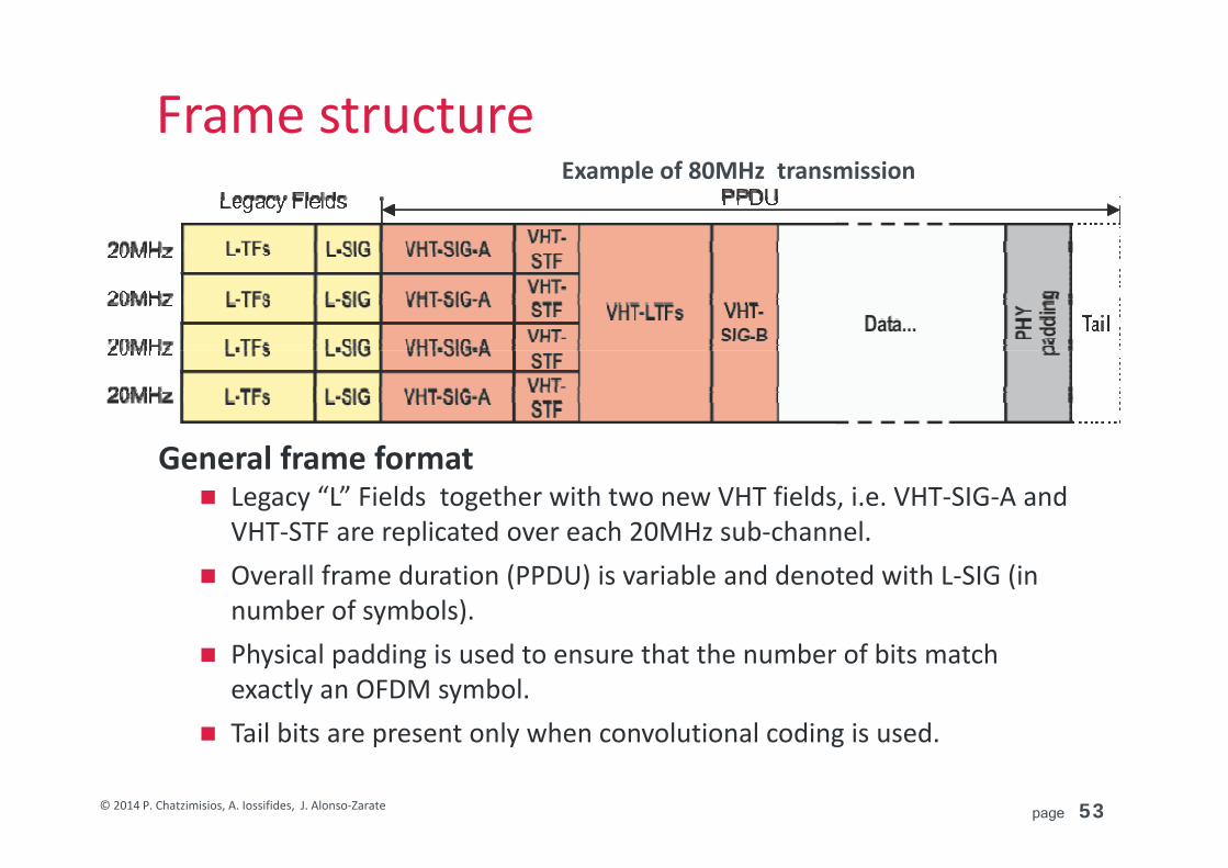
Frame structure
General frame format Legacy “L” Fields together with two new VHT fields, i.e. VHT‐SIG‐A and
VHT‐STF are replicated over each 20MHz sub‐channel. Overall frame duration (PPDU) is variable and denoted with L‐SIG (in
number of symbols). Physical padding is used to ensure that the number of bits match
exactly an OFDM symbol. Tail bits are present only when convolutional coding is used.
Example of 80MHz transmission
page 54© 2014 P. Chatzimisios, A. Iossifides, J. Alonso‐Zarate
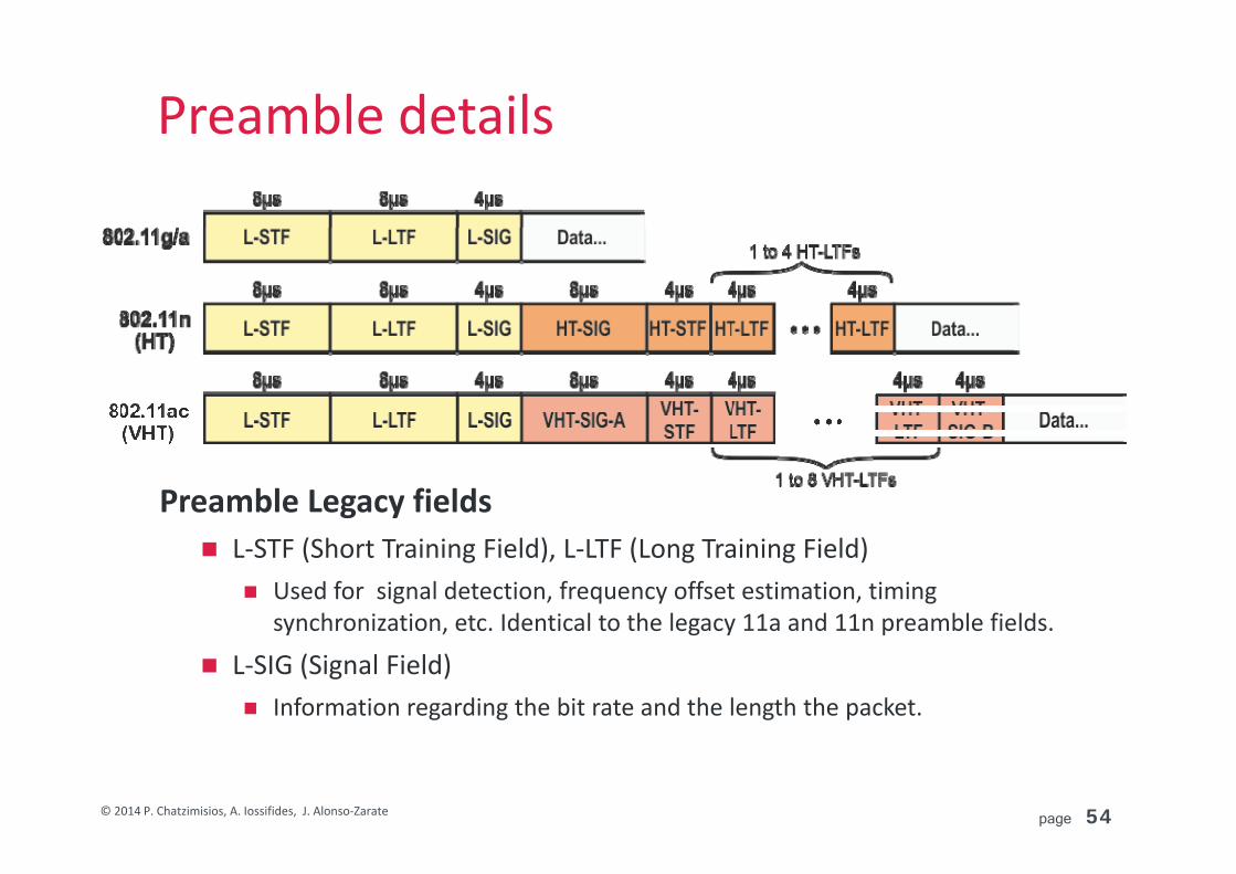
Preamble details
Preamble Legacy fields L‐STF (Short Training Field), L‐LTF (Long Training Field)
Used for signal detection, frequency offset estimation, timing synchronization, etc. Identical to the legacy 11a and 11n preamble fields.
L‐SIG (Signal Field) Information regarding the bit rate and the length the packet.
page 55© 2014 P. Chatzimisios, A. Iossifides, J. Alonso‐Zarate
Preamble details
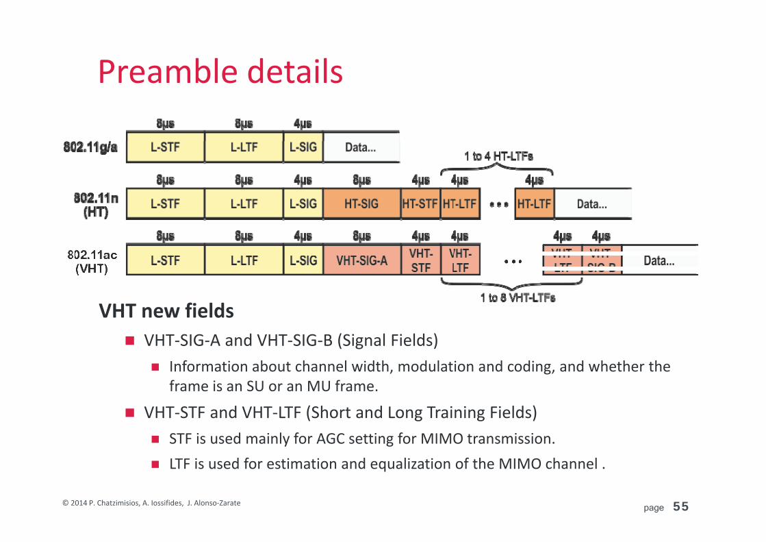
VHT new fields VHT‐SIG‐A and VHT‐SIG‐B (Signal Fields)
Information about channel width, modulation and coding, and whether the frame is an SU or an MU frame.
VHT‐STF and VHT‐LTF (Short and Long Training Fields) STF is used mainly for AGC setting for MIMO transmission. LTF is used for estimation and equalization of the MIMO channel .

page 56© 2014 P. Chatzimisios, A. Iossifides, J. Alonso‐Zarate
Preamble detailsPreamble auto detection
Proper variation of the modulation (BPSK to QBPSK) used by L‐SIG, HT‐SIG, and VHT‐SIG‐A successive symbols allows auto‐detection for legacy, 802.11n and 802.11ac devices.

page 57© 2014 P. Chatzimisios, A. Iossifides, J. Alonso‐Zarate
Preamble details
VHT‐SIG‐A field Single user (SU) version: AP → STAs and STAs → AP with 8 space‐time
streams (SS) supported. Multi‐user (MU) version: AP → STAs with up to 4 SS for 4 users (8 SS max). BPSK modulation with ½ BCC is used for VHT‐SIG‐A.

page 58© 2014 P. Chatzimisios, A. Iossifides, J. Alonso‐Zarate
Preamble details
VHT‐SIG‐B field Single user (SU) version that conveys the length of the packet as a multiple
of 4‐bytes chunks. (max 4692480 bytes vs. 65535 for 802.11n). Multi‐user (MU) version that in addition to the length of the packet
conveys information for the MCS used (not included in multi‐user VHT‐SIG‐A). BPSK modulation with ½ BCC is used for VHT‐SIG‐B.

page 59© 2014 P. Chatzimisios, A. Iossifides, J. Alonso‐Zarate
Preamble details
VHT‐SIG‐B signals are replicated for bandwidth greater than 20MHz as shown in the figure above. The total length matches the number of the available subcarriers (i.e. 52, 108, 234 and 468 subcarriers for 20, 40, 80, 160 MHz, respectively), each one carrying a coded symbol (BCC ½).
page 60© 2014 P. Chatzimisios, A. Iossifides, J. Alonso‐Zarate
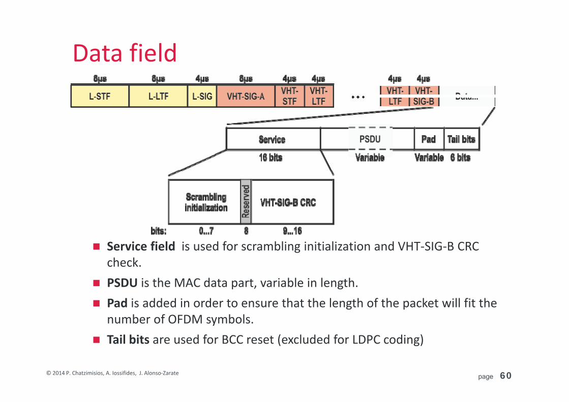
Data field
Service field is used for scrambling initialization and VHT‐SIG‐B CRC check.
PSDU is the MAC data part, variable in length. Pad is added in order to ensure that the length of the packet will fit the
number of OFDM symbols. Tail bits are used for BCC reset (excluded for LDPC coding)

page 61© 2014 P. Chatzimisios, A. Iossifides, J. Alonso‐Zarate
Beamforming and MU‐MIMODiversity and multiplexing methods (1)
Cyclic Shift Diversity (CSD)One spatial stream drives multiple antennas. Received signal minima are avoided by giving each transmit antenna’s signal a large phase shift relative to the others.
Space Time Block Coding (STBC)A number of transmit antennas is used to transmit a known sequence of variants of the original OFDM symbol (e.g. Alamouti21). It can be used for conveying multiple data streams. Requires channel state information (CSI) at the receiver. 21, 42, 63, 84 STBC modes are specified for 802.11ac.
Cyclic Shift Diversity (CSD)
Space Time Block Coding (STBC)

page 62© 2014 P. Chatzimisios, A. Iossifides, J. Alonso‐Zarate
Beamforming and MU‐MIMODiversity and multiplexing methods (2)
BeamformingBeamforming is based on the principle of weighting antenna signals (in amplitude and phase) and steer the beam towards a specific RX antenna. It requires CSI at the transmitter.
Single User MIMO (beamforming)The transmitter is notified by the receiver about the channel matrix H (the gains and phases of each combination of TX and RX antennas) and precodes the transmission with a proper matrix Q to maximize SNR at the receiver. 802.11ac specifies a maximum of up to 8 streams (vs. 4 streams for 802.11n).
Simple beamforming
SU‐MIMO

page 63© 2014 P. Chatzimisios, A. Iossifides, J. Alonso‐Zarate
Beamforming and MU‐MIMODiversity and multiplexing methods (3)
Multi User (MU) MIMO (beamforming)Generalization of SU‐MIMO where multiple users receive information simultaneously (Space Division Multiple Access ‐ SDMA). This is introduced for first time in 802.11ac, which further specifies: Support for up to 8 spatial streams per AP in both SU and MU‐MIMO. No more than 4 spatial streams per client in a MU transmission. All SS have identical MCS for a specific STA
page 64© 2014 P. Chatzimisios, A. Iossifides, J. Alonso‐Zarate
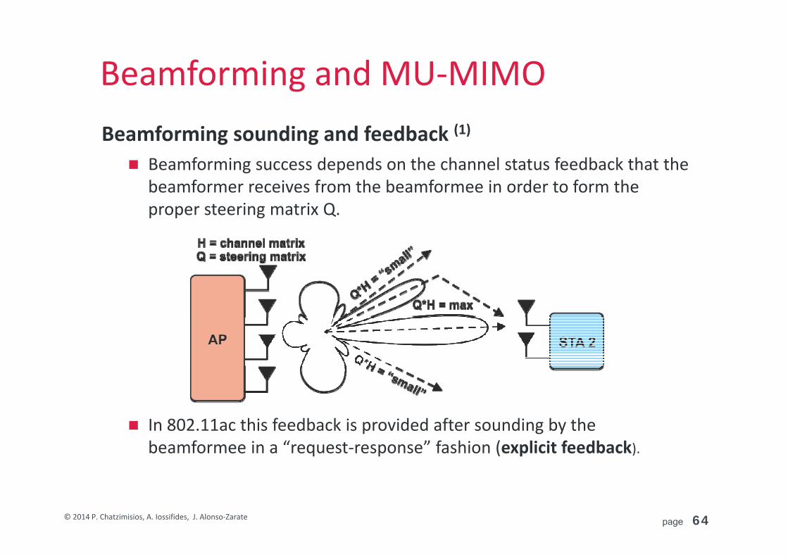
Beamforming and MU‐MIMOBeamforming sounding and feedback (1)
Beamforming success depends on the channel status feedback that the beamformer receives from the beamformee in order to form the proper steering matrix Q.
In 802.11ac this feedback is provided after sounding by the beamformee in a “request‐response” fashion (explicit feedback).
page 65© 2014 P. Chatzimisios, A. Iossifides, J. Alonso‐Zarate
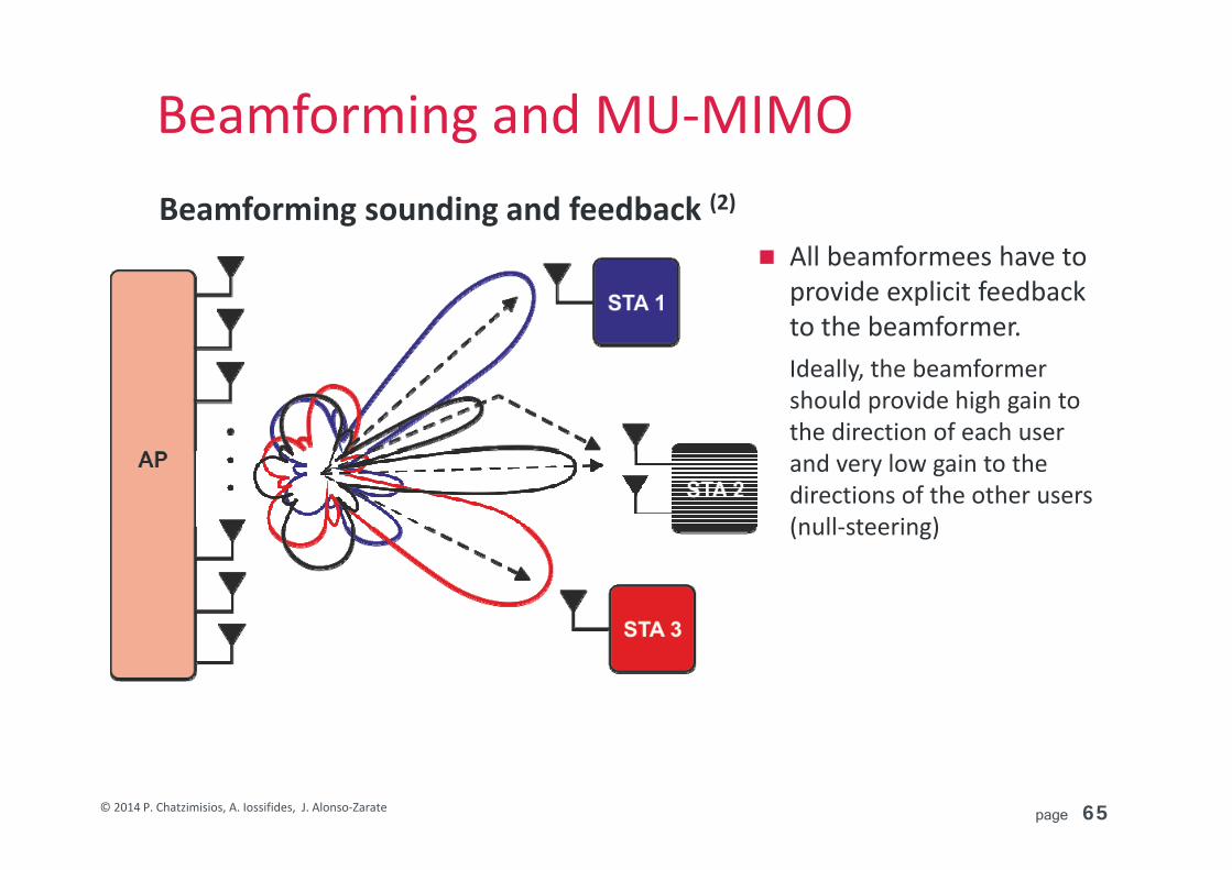
Beamforming and MU‐MIMOBeamforming sounding and feedback (2)
All beamformees have to provide explicit feedback to the beamformer. Ideally, the beamformershould provide high gain to the direction of each user and very low gain to the directions of the other users (null‐steering)
page 66© 2014 P. Chatzimisios, A. Iossifides, J. Alonso‐Zarate
Beamforming and MU‐MIMOBeamforming sounding and feedback (3)
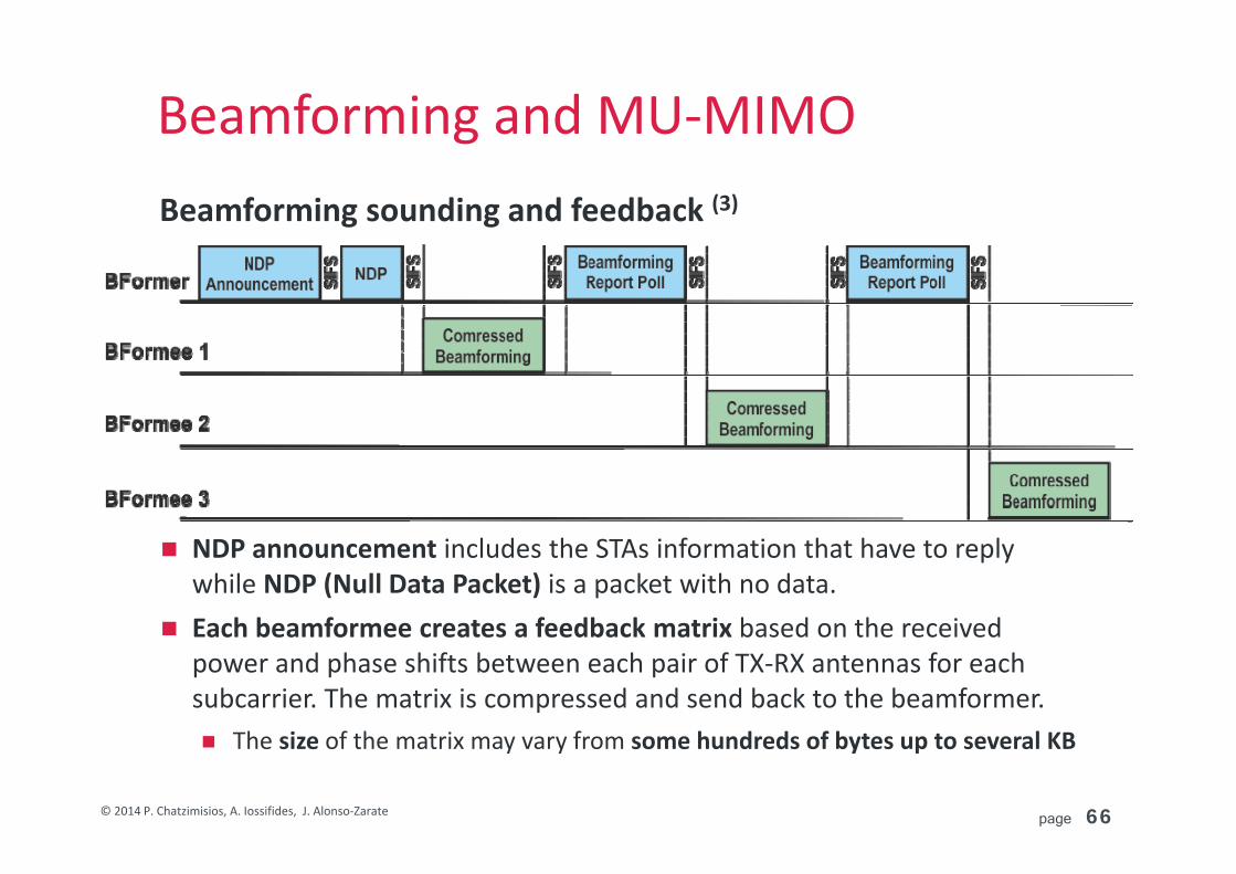
NDP announcement includes the STAs information that have to reply while NDP (Null Data Packet) is a packet with no data.
Each beamformee creates a feedback matrix based on the received power and phase shifts between each pair of TX‐RX antennas for each subcarrier. The matrix is compressed and send back to the beamformer. The size of the matrix may vary from some hundreds of bytes up to several KB

page 67© 2014 P. Chatzimisios, A. Iossifides, J. Alonso‐Zarate
Data transmission and ratesTransmitter block diagram for SU VHT PPDU Data field for 20/40/80 MHz with BCC

page 68© 2014 P. Chatzimisios, A. Iossifides, J. Alonso‐Zarate
Data transmission and ratesTransmitter block diagram for MU VHT PPDU Data field for 20/40/80 MHz with BCC
page 69© 2014 P. Chatzimisios, A. Iossifides, J. Alonso‐Zarate
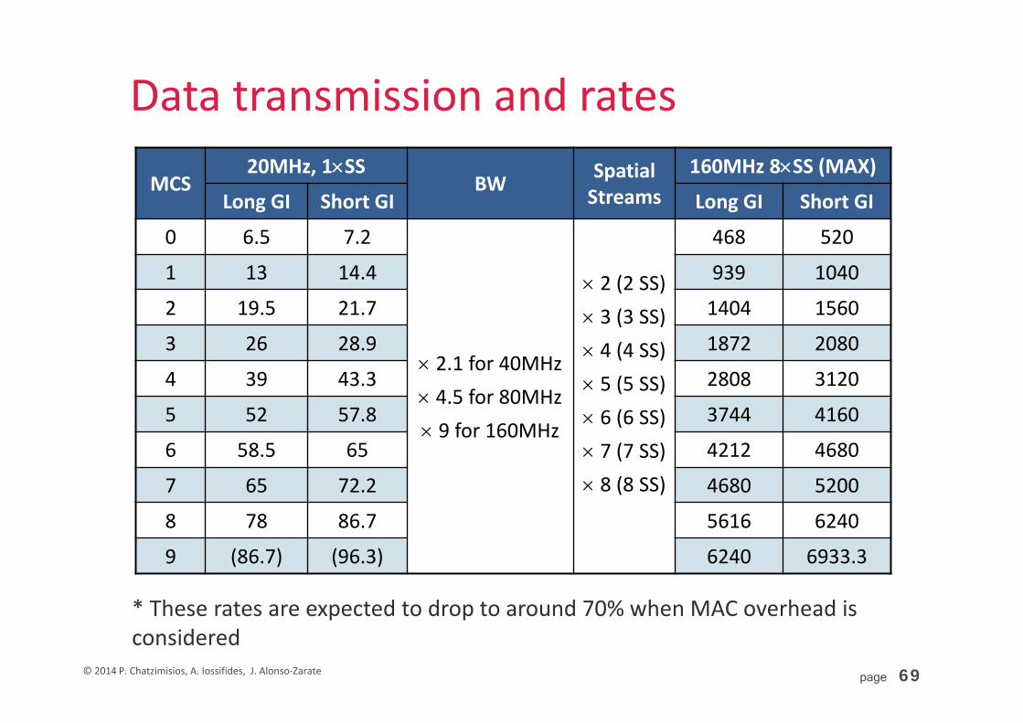
Data transmission and rates
* These rates are expected to drop to around 70% when MAC overhead is considered
MCS20MHz, 1SS
BW Spatial Streams
160MHz 8SS (MAX)
Long GI Short GI Long GI Short GI
0 6.5 7.2
2.1 for 40MHz 4.5 for 80MHz 9 for 160MHz
2 (2 SS) 3 (3 SS) 4 (4 SS) 5 (5 SS) 6 (6 SS) 7 (7 SS) 8 (8 SS)
468 520
1 13 14.4 939 1040
2 19.5 21.7 1404 1560
3 26 28.9 1872 2080
4 39 43.3 2808 3120
5 52 57.8 3744 4160
6 58.5 65 4212 4680
7 65 72.2 4680 5200
8 78 86.7 5616 6240
9 (86.7) (96.3) 6240 6933.3
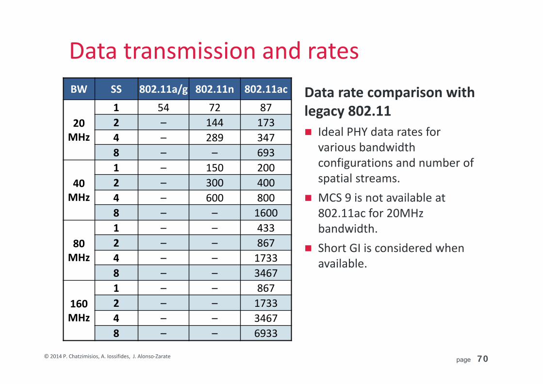
page 70© 2014 P. Chatzimisios, A. Iossifides, J. Alonso‐Zarate
Data transmission and ratesData rate comparison with legacy 802.11 Ideal PHY data rates for
various bandwidth configurations and number of spatial streams.
MCS 9 is not available at 802.11ac for 20MHz bandwidth.
Short GI is considered when available.
BW SS 802.11a/g 802.11n 802.11ac
20MHz
1 54 72 872 – 144 1734 – 289 3478 – – 693
40MHz
1 – 150 2002 – 300 4004 – 600 8008 – – 1600
80MHz
1 – – 4332 – – 8674 – – 17338 – – 3467
160MHz
1 – – 8672 – – 17334 – – 34678 – – 6933

page 71© 2014 P. Chatzimisios, A. Iossifides, J. Alonso‐Zarate
Example scenarios
AP ant.
STAant. Client type SS
(max)BW(MHz)
MCS (with short GI)
IndividualThroughput
AggregateThroughput
2 1 Smartphone 1 80
256QAM, 5/6
433.3 433.3
4 22
LaptopSmartphone
22 80 866.7
866.7 1733.3
4
1111
SmartphoneSmartphoneTabletTablet
1111
160
866.7866.7866.7866.7
3466.8
8
1124
SmartphoneTabletLaptopDigital TV
1124
160
866.7866.71733.33466.7
6933.3
8 44
PCDigital TV
44 160 3466.7
3466.7 6933.3

page 72© 2014 P. Chatzimisios, A. Iossifides, J. Alonso‐Zarate
Mandatory and optional features
Attribute Mandatory Optional
Bandwidth 20,40,80 160, 80+80
MCS 0..7 (up to 64QAM 5/6) 8, 9 (256QAM 3/4 and 5/6)
Spatial streams 1 2‐8 (same MCS)
Guard Interval Long Short
FEC BCC (convolutional) LDPC
STBC 21, 42, 63, 84
Multi User 4 SS per client (same MCS)

page 73© 2014 P. Chatzimisios, A. Iossifides, J. Alonso‐Zarate
IEEE 802.11ac, VHT below 6 GHz2.1 Key features and use cases2.2 Physical layer description (PHY)
2.3 MAC layer description (MAC)

page 74© 2014 P. Chatzimisios, A. Iossifides, J. Alonso‐Zarate
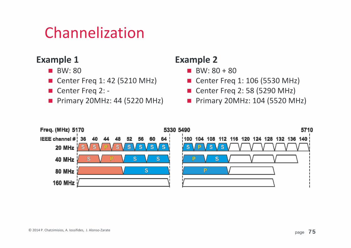
Primary and secondary channels Channels include a 20 (40/60/80) MHz primary channel and are
specified (and signaled) by four parameters: Current channel bandwidth (20, 40, 80, 160, 80+80) Current channel Center Frequency 1 Current channel Center Frequency 2 (in case of 80 + 80 MHz allocation) Current primary 20MHz channel
Channelization
page 75© 2014 P. Chatzimisios, A. Iossifides, J. Alonso‐Zarate
ChannelizationExample 2 BW: 80 + 80 Center Freq 1: 106 (5530 MHz) Center Freq 2: 58 (5290 MHz) Primary 20MHz: 104 (5520 MHz)
Example 1 BW: 80 Center Freq 1: 42 (5210 MHz) Center Freq 2: ‐ Primary 20MHz: 44 (5220 MHz)
page 76© 2014 P. Chatzimisios, A. Iossifides, J. Alonso‐Zarate
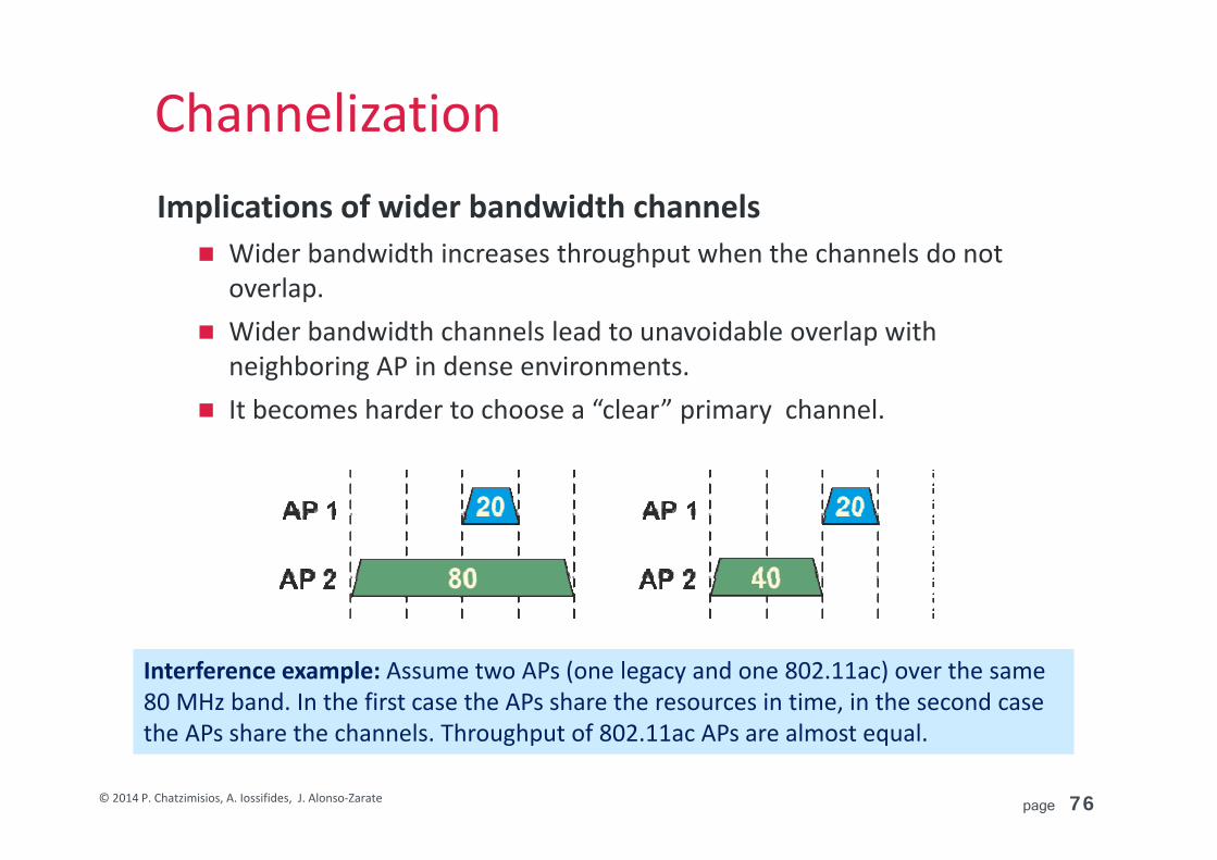
ChannelizationImplications of wider bandwidth channels Wider bandwidth increases throughput when the channels do not
overlap. Wider bandwidth channels lead to unavoidable overlap with
neighboring AP in dense environments. It becomes harder to choose a “clear” primary channel.
Interference example: Assume two APs (one legacy and one 802.11ac) over the same 80 MHz band. In the first case the APs share the resources in time, in the second case the APs share the channels. Throughput of 802.11ac APs are almost equal.
page 77© 2014 P. Chatzimisios, A. Iossifides, J. Alonso‐Zarate
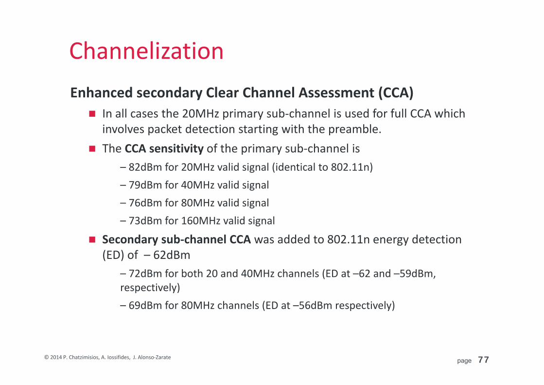
ChannelizationEnhanced secondary Clear Channel Assessment (CCA) In all cases the 20MHz primary sub‐channel is used for full CCA which
involves packet detection starting with the preamble. The CCA sensitivity of the primary sub‐channel is
– 82dBm for 20MHz valid signal (identical to 802.11n)– 79dBm for 40MHz valid signal– 76dBm for 80MHz valid signal– 73dBm for 160MHz valid signal
Secondary sub‐channel CCA was added to 802.11n energy detection (ED) of – 62dBm
– 72dBm for both 20 and 40MHz channels (ED at –62 and –59dBm, respectively)– 69dBm for 80MHz channels (ED at –56dBm respectively)

page 78© 2014 P. Chatzimisios, A. Iossifides, J. Alonso‐Zarate
Co‐channel operationProblem The 802.11ac AP could be nearby other uncoordinated APs. Different APs and their associated clients have a different virtual carrier
sense, so can transmit at different times on the different subchannels, including overlapping times.
Solution via a three step procedure (1) The 802.11ac device sends an RTS with BW indication over the
primary 20MHz channel (replicated 3/ 7 times for 80/160 MHz).
(2) The recipient device checks to see if there is anyone transmitting near itself on its primary channel or on any other 20 MHz within the 80 MHz.
(3) CTS is sent, replicated in 20 MHz chunks across the available and useful bandwidth.
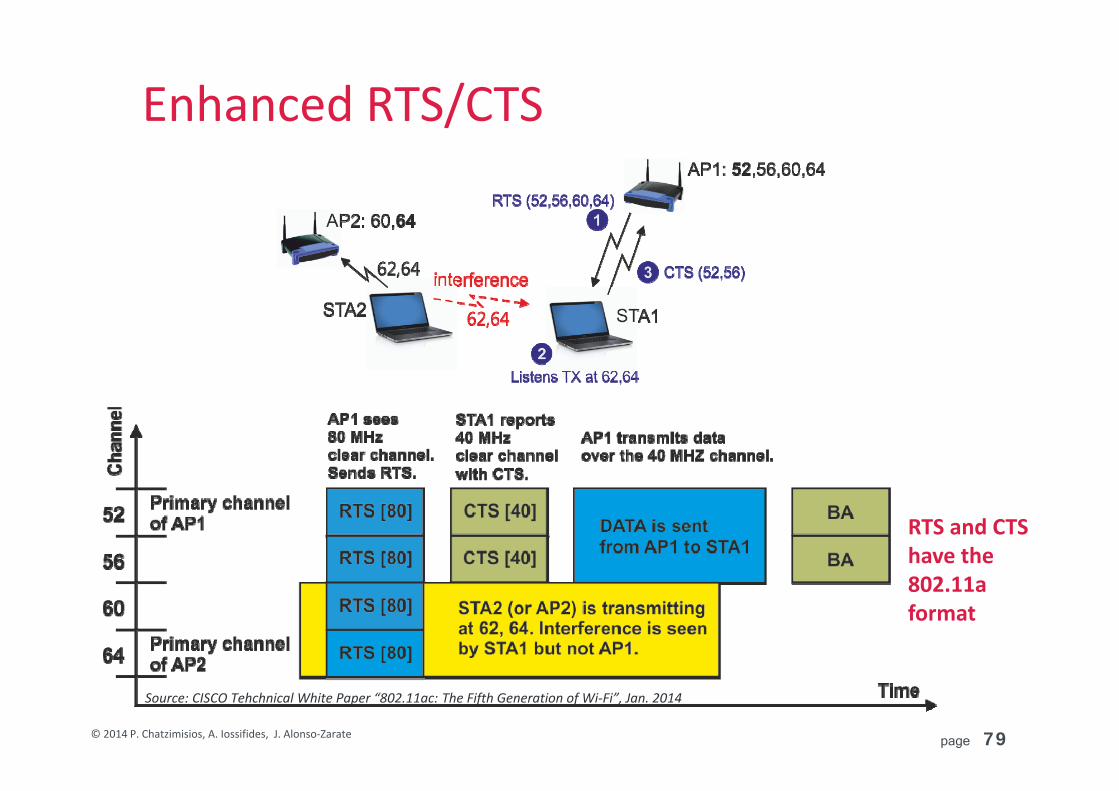
page 79© 2014 P. Chatzimisios, A. Iossifides, J. Alonso‐Zarate
Enhanced RTS/CTS
RTS and CTS have the 802.11a format
Source: CISCO Tehchnical White Paper “802.11ac: The Fifth Generation of Wi‐Fi”, Jan. 2014

page 80© 2014 P. Chatzimisios, A. Iossifides, J. Alonso‐Zarate
Co‐channel example
Comments With the wider channel, more clients get to transfer their data more
quickly and they can complete their transmissions much sooner. Overall, less battery energy is consumed, and other clients don’t have to wait long (leading to better QoS).
Careful coordination is required among BSS to get the most out of 802.11ac (e.g. a centralized RRM strategy?)
Example of two 802.11ac AP sharing the same band

page 81© 2014 P. Chatzimisios, A. Iossifides, J. Alonso‐Zarate
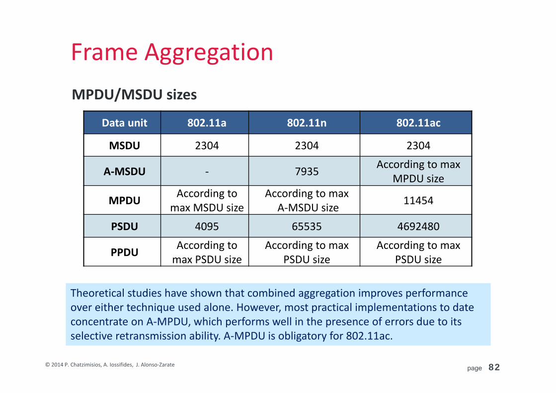
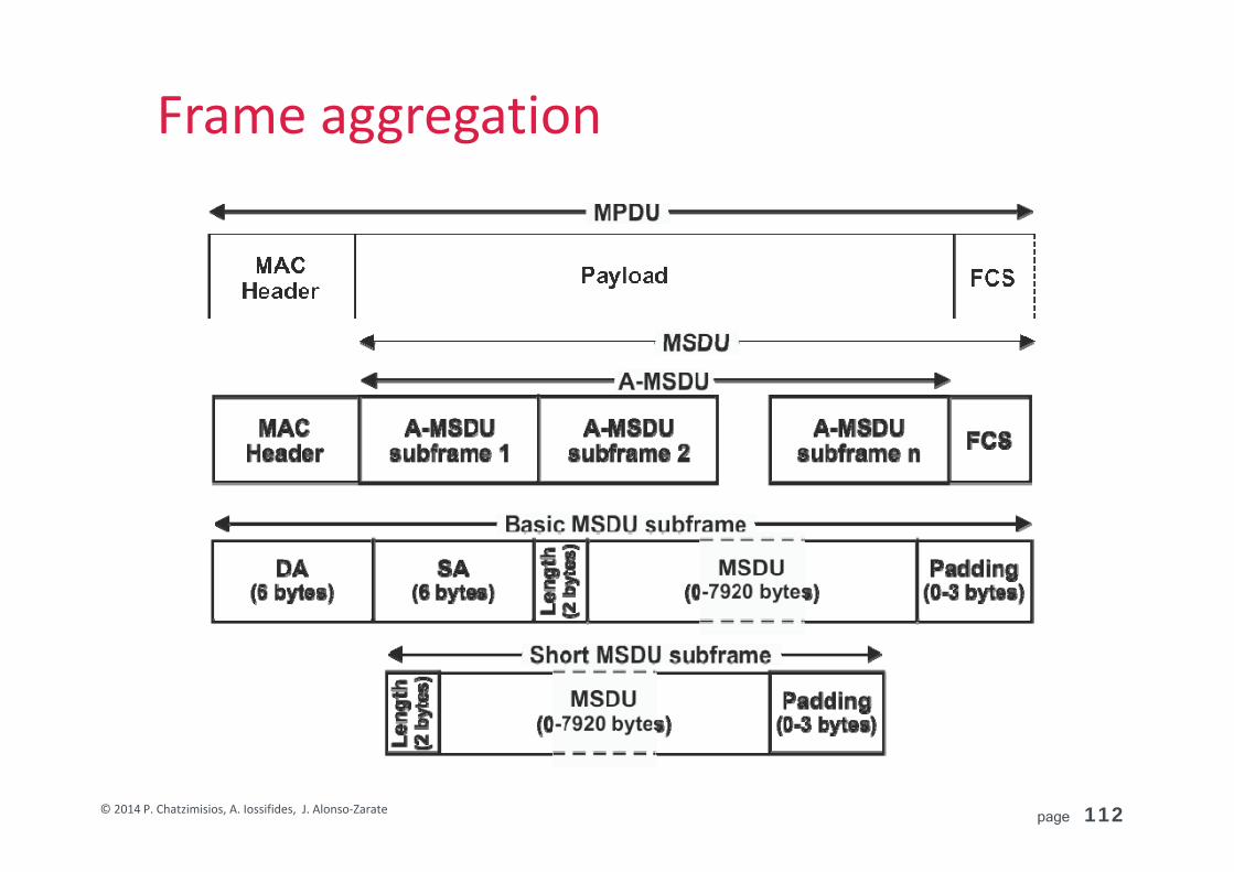
Frame Aggregation
Source: CISCO Tehchnical White Paper “802.11ac: The Fifth Generation of Wi‐Fi”, Jan. 2014
page 82© 2014 P. Chatzimisios, A. Iossifides, J. Alonso‐Zarate
Frame AggregationMPDU/MSDU sizes
Data unit 802.11a 802.11n 802.11ac
MSDU 2304 2304 2304
A‐MSDU ‐ 7935 According to max MPDU size
MPDU According to max MSDU size
According to maxA‐MSDU size 11454
PSDU 4095 65535 4692480
PPDU According to max PSDU size
According to max PSDU size
According to max PSDU size
Theoretical studies have shown that combined aggregation improves performance over either technique used alone. However, most practical implementations to date concentrate on A‐MPDU, which performs well in the presence of errors due to its selective retransmission ability. A‐MPDU is obligatory for 802.11ac.
page 83© 2014 P. Chatzimisios, A. Iossifides, J. Alonso‐Zarate
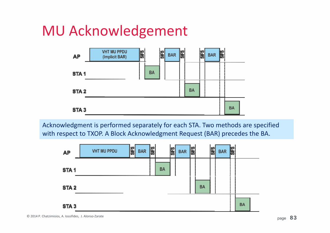
MU Acknowledgement
Acknowledgment is performed separately for each STA. Two methods are specified with respect to TXOP. A Block Acknowledgment Request (BAR) precedes the BA.

page 84© 2014 P. Chatzimisios, A. Iossifides, J. Alonso‐Zarate
Services example
page 85© 2014 P. Chatzimisios, A. Iossifides, J. Alonso‐Zarate
Co‐existence with legacy 802.11
Transmitter type 802.11a receiver 802.11n receiver 802.11ac receiver
802.11a ‐802.11n devices may receive 802.11a frames
802.11ac devices may receive 802.11a frames
802.11n
802.11n device transmits 802.11aframes (backward compatibility)
‐802.11ac devices may receive 802.11n frames
802.11ac
802.11ac device transmits 802.11aframes (backward compatibility)
802.11ac device transmits 802.11nframes (backward compatibility)
‐

page 86© 2014 P. Chatzimisios, A. Iossifides, J. Alonso‐Zarate
IEEE 802.11ad, DMG at 60 GHz3.1 Key features and use cases3.2 Physical layer description (PHY)3.3 MAC layer description (MAC)

page 87© 2014 P. Chatzimisios, A. Iossifides, J. Alonso‐Zarate
IEEE 802.11ad, DMG at 60 GHz3.1 Key features and use cases3.2 Physical layer description (PHY)3.3 MAC layer description (MAC)

page 88© 2014 P. Chatzimisios, A. Iossifides, J. Alonso‐Zarate
Use cases
Use cases
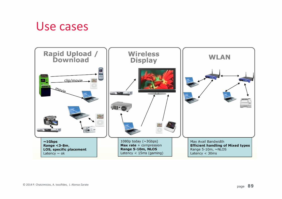
page 89© 2014 P. Chatzimisios, A. Iossifides, J. Alonso‐Zarate
Use cases
Use cases

page 90© 2014 P. Chatzimisios, A. Iossifides, J. Alonso‐Zarate
Key featuresSupport for data rates of up to 7 Gbit/s Different modes, starting from an energy‐saving single carrier mode
towards a high‐performance mode with OFDM technology for very high throughput (DMG ‐ Directional Multi Gigabit) .
Ultra wide bandwidth allocation (2.16GHz)
Use of the 60 GHz unlicensed band Global availability avoiding the overcrowded 2.4 GHz and 5 GHz bands.
Short wavelengths (i.e. 5 mm) that make compact and affordable antennas or antenna arrays possible.
Short ranges (1‐10m usually, less than 100m)
Beamforming Power optimization at the receiver and overcomes interference during
the transmission in real time.

page 91© 2014 P. Chatzimisios, A. Iossifides, J. Alonso‐Zarate
IEEE 802.11ad, DMG at 60 GHz3.1 Key features and use cases
3.2 Physical layer description (PHY)3.3 MAC layer description (MAC)

page 92© 2014 P. Chatzimisios, A. Iossifides, J. Alonso‐Zarate
Frequency and ChannelizationFrequency band 802.11ad specifies the 60GHz (57‐66 GHz) unlicensed band for the
Directional Multi‐Gigabit (DMG) transmission with a channel bandwidth of 2.160 GHz.
Link budget considerations 1m free space path loss raises to 68dB (47dB for 5GHz) and 88dB for 10m. Increased bandwidth results to higher noise power (17dB more w.r.t.
40MHz HT/VHT‐PHY). Wall attenuation 20‐60dB, human attenuation 10‐15dB. Oxygen absorption. Transmission power in the order of 10 dBm.
Directional transmission (beamforming) is required High frequency makes possible the construction of small size antenna
arrays that will ideally “follow” the movement of the receiver.

page 93© 2014 P. Chatzimisios, A. Iossifides, J. Alonso‐Zarate
Frequency and ChannelizationChannels 4 channels are defined with 2.160 GHz bandwidth each.

page 94© 2014 P. Chatzimisios, A. Iossifides, J. Alonso‐Zarate
Frequency and ChannelizationSpectrum mask
Spectrum mask requirements are relaxed (compared to HT and VHT PHY) in order to simplify hardware implementation in the 60 GHz band. The requirements cover all modes of the physical layer (Single carrier and OFDM).

page 95© 2014 P. Chatzimisios, A. Iossifides, J. Alonso‐Zarate
DMG descriptionDMG modes
(1) Control PHY Single carrier transmission designed for low SNR operation prior to
beamforming. One MCS scheme with a bit rate of 27.5 Mbps.
(2) Single Carrier (SC) PHY Single Carrier transmission for low power/complexity transmission.
12 MCS schemes with a max bit rate of 4.62 Gbps.
(2a) Low power SC PHY variant Provides additional support for further reduction in processing power.
7 MCS schemes with a max bit rate of 2.5 Gbps.
(3) OFDM PHY High performance for frequency selective channels that achieves the
maximum data rates. 12 MCS schemes with a max bit rate of 6.76 Gbps.
page 96© 2014 P. Chatzimisios, A. Iossifides, J. Alonso‐Zarate
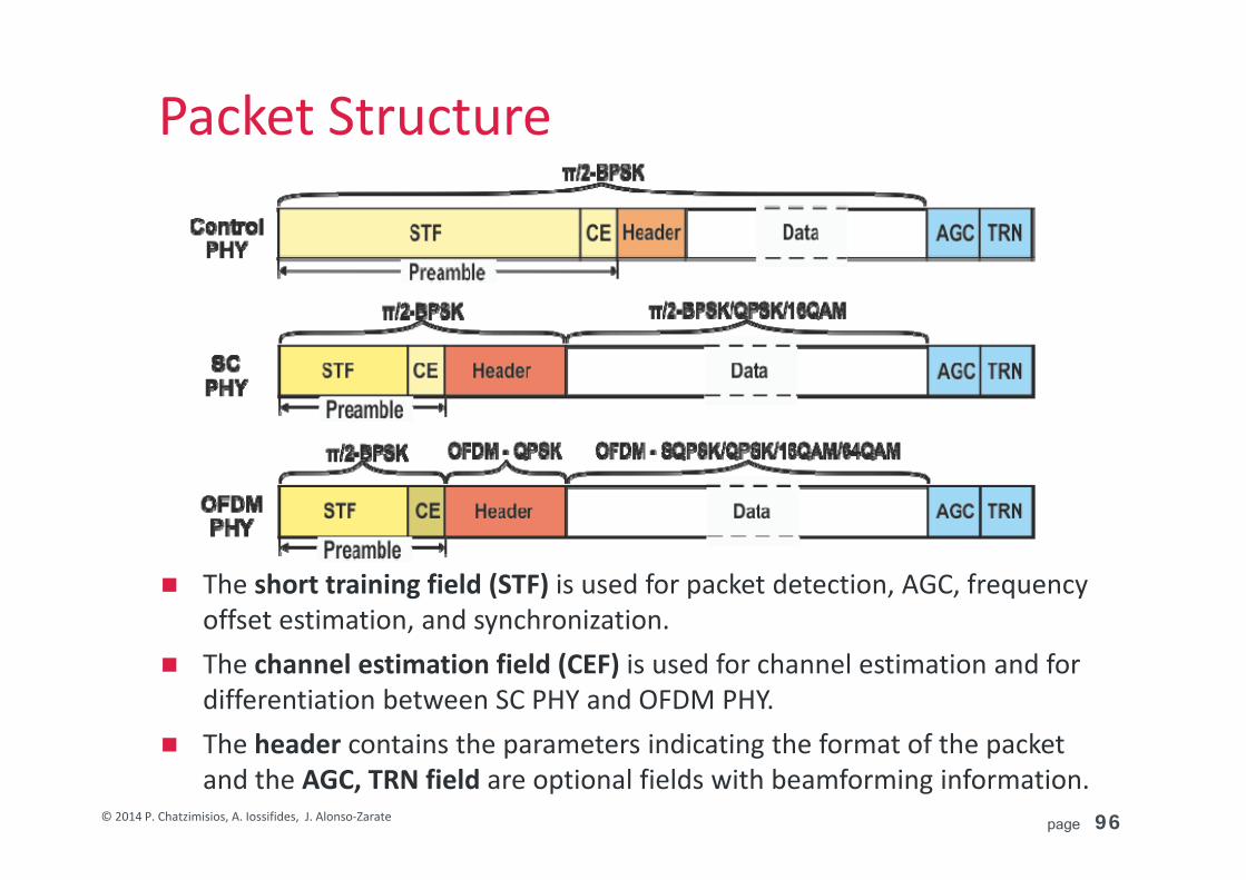
Packet Structure
The short training field (STF) is used for packet detection, AGC, frequency offset estimation, and synchronization.
The channel estimation field (CEF) is used for channel estimation and for differentiation between SC PHY and OFDM PHY.
The header contains the parameters indicating the format of the packet and the AGC, TRN field are optional fields with beamforming information.

page 97© 2014 P. Chatzimisios, A. Iossifides, J. Alonso‐Zarate
Preamble
Both STF and CEF fields are constructed by combinations of the Complementary Golay sequences Ga128 and Gb128.
The differences in the combinations allow the receiver to discriminate among the different modes.
The sequences Gu512 and Gv512 have even better autocorrelation and cross correlation properties that allow effective channel estimation.

page 98© 2014 P. Chatzimisios, A. Iossifides, J. Alonso‐Zarate
Header
CPHY does not contain an MCS field, since CPHY MCS is only one. Length field defines the length of the Data field in octets. BTR (Beam Tracking Request) indicates requests regarding beamforming
training. Packet Type differentiates between BTR for transmitter and receiver. Training length defines the length of the TRN
Tone Pairing and Dynamic Tone Pairing (DTP) refer to OFDM static and dynamic pairing characteristics.
page 99© 2014 P. Chatzimisios, A. Iossifides, J. Alonso‐Zarate
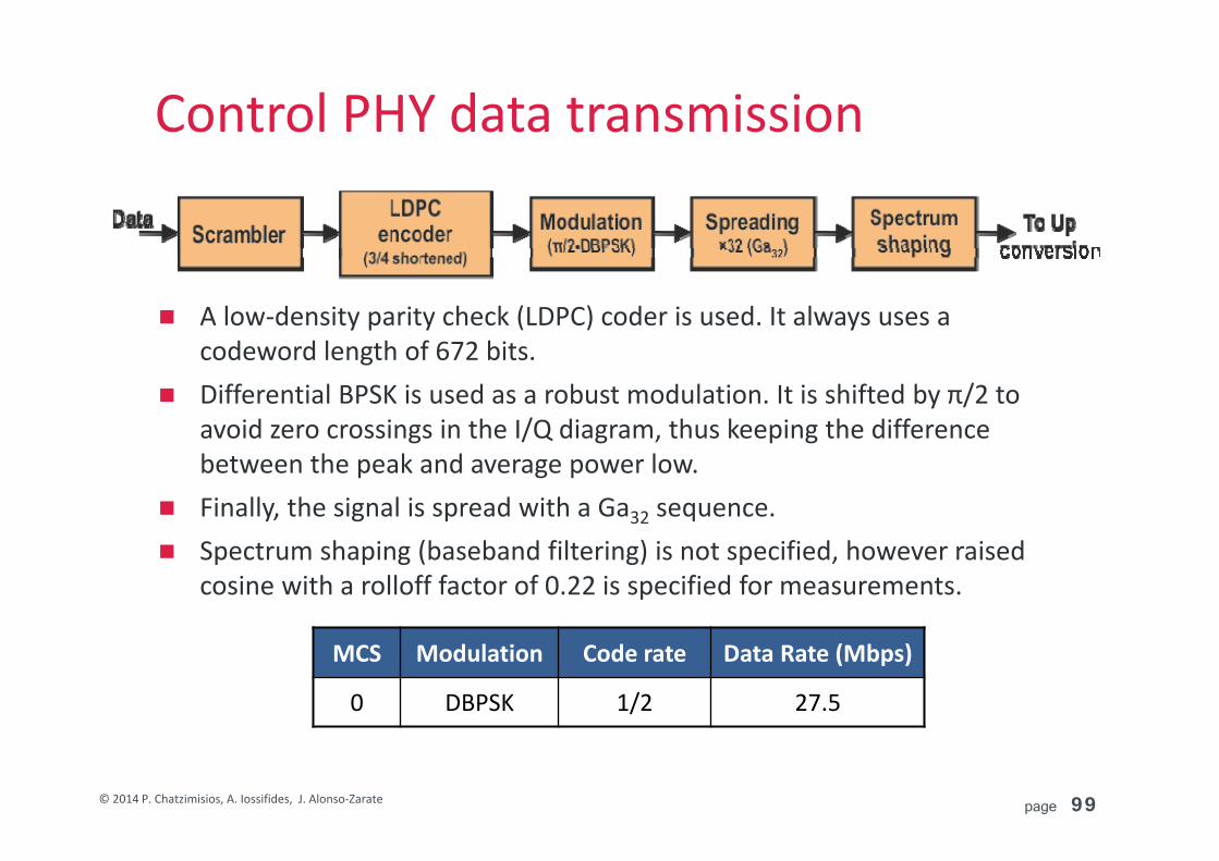
Control PHY data transmission
A low‐density parity check (LDPC) coder is used. It always uses a codeword length of 672 bits.
Differential BPSK is used as a robust modulation. It is shifted by π/2 to avoid zero crossings in the I/Q diagram, thus keeping the difference between the peak and average power low.
Finally, the signal is spread with a Ga32 sequence. Spectrum shaping (baseband filtering) is not specified, however raised
cosine with a rolloff factor of 0.22 is specified for measurements.
MCS Modulation Code rate Data Rate (Mbps)
0 DBPSK 1/2 27.5

page 100© 2014 P. Chatzimisios, A. Iossifides, J. Alonso‐Zarate
SC PHY data transmission
The length of the Data field may vary from 1 to 262143 octets. Variable modulation depth and LDPC coding rates are defined. The data are transmitted blockwise at 448 symbols per block. Another 64
symbols are inserted between the individual blocks as guard intervals (GI) in order to provide a known reference signal to the receiver for in the case of long data packets.

page 101© 2014 P. Chatzimisios, A. Iossifides, J. Alonso‐Zarate
SC PHY data transmissionMCS Support of MCSs 1‐4 is
mandatory to comply with original TGad PAR that requires 1Gpbs data rates.
In MCS 1 data bits are repeated twice.
MCS Modulation Code rate Data Rate (Mbps)
1 π/2‐BPSK 1/2 385
2 π/2‐BPSK 1/2 770
3 π/2‐BPSK 5/8 962.5
4 π/2‐BPSK 3/4 1155
5 π/2‐BPSK 13/16 1251.55
6 π/2‐QPSK 1/2 1540
7 π/2‐QPSK 5/8 1925
8 π/2‐QPSK 3/4 2310
9 π/2‐QPSK 13/16 2502.5
10 π/2‐16QAM 1/2 3080
11 π/2‐16QAM 5/8 3850
12 π/2‐16QAM 3/4 4620
page 102© 2014 P. Chatzimisios, A. Iossifides, J. Alonso‐Zarate
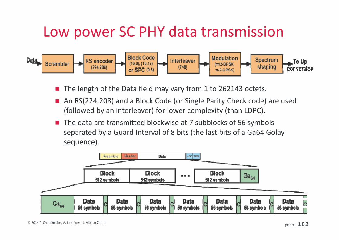
Low power SC PHY data transmission
The length of the Data field may vary from 1 to 262143 octets. An RS(224,208) and a Block Code (or Single Parity Check code) are used
(followed by an interleaver) for lower complexity (than LDPC). The data are transmitted blockwise at 7 subblocks of 56 symbols
separated by a Guard Interval of 8 bits (the last bits of a Ga64 Golaysequence).

page 103© 2014 P. Chatzimisios, A. Iossifides, J. Alonso‐Zarate
Low power SC PHY data transmission
There are always 392 data symbols per block of 512 symbols.
MCS Modulation Effectivecode rate Coding Scheme Data Rate
(Mbps)
25 π/2‐BPSK 13/28 RS(224,208) + Block Code (16,8) 626
26 π/2‐BPSK 13/21 RS(224,208) + Block Code (12,8) 834
27 π/2‐BPSK 52/63 RS(224,208) + SPC (9,8) 1112
28 π/2‐QPSK 13/28 RS(224,208) + Block Code (16,8) 1251
29 π/2‐QPSK 13/21 RS(224,208) + Block Code (12,8) 1668
30 π/2‐QPSK 52/63 RS(224,208) + SPC(9,8) 2224
31 π/2‐QPSK 13/14 RS(224,208) + Block Code (8,8) 2503

page 104© 2014 P. Chatzimisios, A. Iossifides, J. Alonso‐Zarate
OFDM PHY data transmission
The length of the Data field may vary from 1 to 262143 octets. LDPC coding is used with a block length of 672 bits. 4 modulation schemes are defined, up to 64QAM. OFDM includes 355 subcarriers in total (336 data subcarriers) with
5.15625 MHz subcarrier spacing. 16 pilot tones are inserted at ‐150, ‐130, ‐110, ‐90, ‐70, ‐50, ‐30, ‐10, 10,
30, 50, 70, 90, 110, 130, 150 subcarriers. 3 null tones are inserted at ‐1, 0 1 subcarriers.
page 105© 2014 P. Chatzimisios, A. Iossifides, J. Alonso‐Zarate
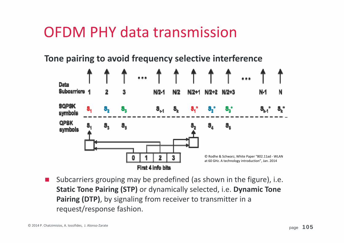
OFDM PHY data transmissionTone pairing to avoid frequency selective interference
Subcarriers grouping may be predefined (as shown in the figure), i.e. Static Tone Pairing (STP) or dynamically selected, i.e. Dynamic Tone Pairing (DTP), by signaling from receiver to transmitter in a request/response fashion.
© Rodhe & Schwarz, White Paper “802.11ad ‐WLAN at 60 GHz. A technology introduction”, Jan. 2014
page 106© 2014 P. Chatzimisios, A. Iossifides, J. Alonso‐Zarate
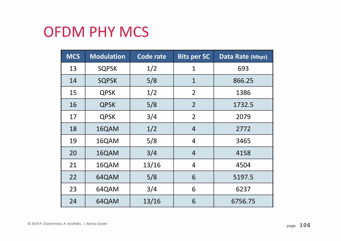
OFDM PHY MCSMCS Modulation Code rate Bits per SC Data Rate (Mbps)
13 SQPSK 1/2 1 693
14 SQPSK 5/8 1 866.25
15 QPSK 1/2 2 1386
16 QPSK 5/8 2 1732.5
17 QPSK 3/4 2 2079
18 16QAM 1/2 4 2772
19 16QAM 5/8 4 3465
20 16QAM 3/4 4 4158
21 16QAM 13/16 4 4504
22 64QAM 5/8 6 5197.5
23 64QAM 3/4 6 6237
24 64QAM 13/16 6 6756.75
page 107© 2014 P. Chatzimisios, A. Iossifides, J. Alonso‐Zarate
IEEE 802.11ad, DMG at 60 GHz3.1 Key features and use cases3.2 Physical layer description (PHY)
3.3 MAC layer description (MAC)
page 108© 2014 P. Chatzimisios, A. Iossifides, J. Alonso‐Zarate
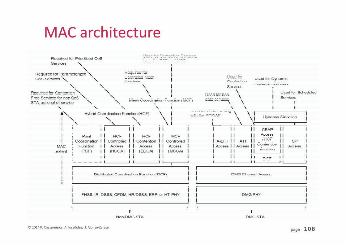
MAC architecture
page 109© 2014 P. Chatzimisios, A. Iossifides, J. Alonso‐Zarate
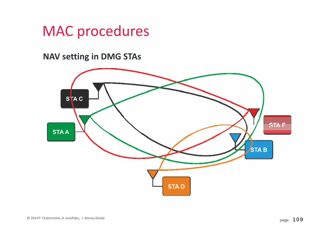
MAC proceduresNAV setting in DMG STAs

page 110© 2014 P. Chatzimisios, A. Iossifides, J. Alonso‐Zarate
MAC proceduresBackoff procedure for DMG STAs

page 111© 2014 P. Chatzimisios, A. Iossifides, J. Alonso‐Zarate
Frame aggregation
page 112© 2014 P. Chatzimisios, A. Iossifides, J. Alonso‐Zarate
Frame aggregation

page 113© 2014 P. Chatzimisios, A. Iossifides, J. Alonso‐Zarate
PBSSPersonal Basic Service Set (PBSS) Group of stations that communicate (without an AP)
PBSS Central Point (PCP): One station (considered as the PCP) provides scheduling and timing using beacons Only the PCP can send a beacon during beacon time
Each super‐frame called “Beacon Interval” is divided into: Beacon Transmission Interval (BTI): During BTI discovery of new stations
occurs
Associating Beamforming Training (A‐BFT): PCP performance antenna training with its members
Announcement Time (ATI): PCP polls members and receives non‐data responses
Data Transfer Time (DTT): All stations exchange data frames in a dedicated Service Period (SP) or by contention in Contention‐Based Period (CBP)

page 114© 2014 P. Chatzimisios, A. Iossifides, J. Alonso‐Zarate
PBSS

page 115© 2014 P. Chatzimisios, A. Iossifides, J. Alonso‐Zarate
Beamforming protocol
Source: S.‐E. Hong, “IEEE 802.11ad”, ETRI IT R&D Global Leader.

page 116© 2014 P. Chatzimisios, A. Iossifides, J. Alonso‐Zarate
Beamforming protocolBeacon Transmission Interval (BTI) During BTI, discovery of new stations
occurs A PCP performs one or more beacon
transmissions potentially in different directions
Beacon transmissions are omni‐directional (one beacon is transmitted through every antenna configuration)

page 117© 2014 P. Chatzimisios, A. Iossifides, J. Alonso‐Zarate
Beamforming protocolAssociation Beam/ing Training (A‐BFT) An access period during which
beamforming training is performed between the PCP and the stations (STAs) (with the STA that transmitted a Beacon frame during the preceding BTI)
Antenna training occurs and each station finds the optimal antenna configuration with its recipient using a two‐stage search: Sector Level Sweep (SLS): First it sends in all
sectors and finds the optimal sector (sector selection)
Beam Refinement Procedure (BRP): It searches through the optimal sector to find the optimal parameters in that sector (fine tuning)

page 118© 2014 P. Chatzimisios, A. Iossifides, J. Alonso‐Zarate
Beamforming protocolAnnouncement Time (ATI) A request‐response based
management access period between PCP and STAs (association, schedule)
Request and response frames transmitted during the ATI are one of the following: A frame of type Management An ACK frame A Grant, Poll, RTS or DMG CTS
frame when transmitted as a request frame
A DMG CTS frame when transmitted as a response frame

page 119© 2014 P. Chatzimisios, A. Iossifides, J. Alonso‐Zarate
Beamforming protocol
Data Transfer Interval (DTI): An access period during which frame exchanges are performed between STAs All stations exchange data frames by contention in a Contention‐Based
Access Periods (CBAPs) and scheduled Service Periods (SPs) During CBAPs, stations use either Distributed Coordination Function
(DCF) or Hybrid Coordination Function (HCF). Directional Band CTS (Dband CTS) is used with Transmitter Address (TA) field. NAV is maintained for each source and destination pair
During SPs, channel access is coordinated by a schedule that decides the PCP (access is given to specific stations)

page 120© 2014 P. Chatzimisios, A. Iossifides, J. Alonso‐Zarate
New emerging amendments
page 121© 2014 P. Chatzimisios, A. Iossifides, J. Alonso‐Zarate
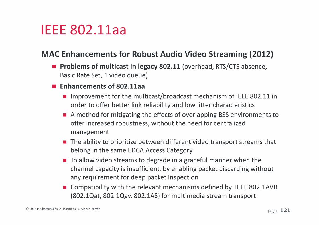
IEEE 802.11aaMAC Enhancements for Robust Audio Video Streaming (2012) Problems of multicast in legacy 802.11 (overhead, RTS/CTS absence,
Basic Rate Set, 1 video queue)
Enhancements of 802.11aa Improvement for the multicast/broadcast mechanism of IEEE 802.11 in
order to offer better link reliability and low jitter characteristics A method for mitigating the effects of overlapping BSS environments to
offer increased robustness, without the need for centralized management
The ability to prioritize between different video transport streams that belong in the same EDCA Access Category
To allow video streams to degrade in a graceful manner when the channel capacity is insufficient, by enabling packet discarding without any requirement for deep packet inspection
Compatibility with the relevant mechanisms defined by IEEE 802.1AVB (802.1Qat, 802.1Qav, 802.1AS) for multimedia stream transport
page 122© 2014 P. Chatzimisios, A. Iossifides, J. Alonso‐Zarate
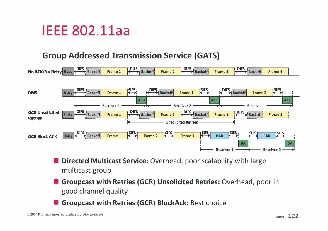
IEEE 802.11aaGroup Addressed Transmission Service (GATS)
Directed Multicast Service: Overhead, poor scalability with large multicast group
Groupcast with Retries (GCR) Unsolicited Retries: Overhead, poor in good channel quality
Groupcast with Retries (GCR) BlockAck: Best choice

page 123© 2014 P. Chatzimisios, A. Iossifides, J. Alonso‐Zarate
IEEE 802.11aaStream Classification Service (SCS)

page 124© 2014 P. Chatzimisios, A. Iossifides, J. Alonso‐Zarate
IEEE 802.11aaUser
priorityDesignation 802.11e
AC queue802.11aa AC queue
0 (lowest) Best effort (BE) BE BE
1 Background (BK) BK BK
2 Spare BK BK
3 Excellent effort BE BE
4 Controlled load VI A_VI
5 Video (VI) VI VI
6 Voice VO VO
7 (highest) Network control VO A_VO
page 125© 2014 P. Chatzimisios, A. Iossifides, J. Alonso‐Zarate
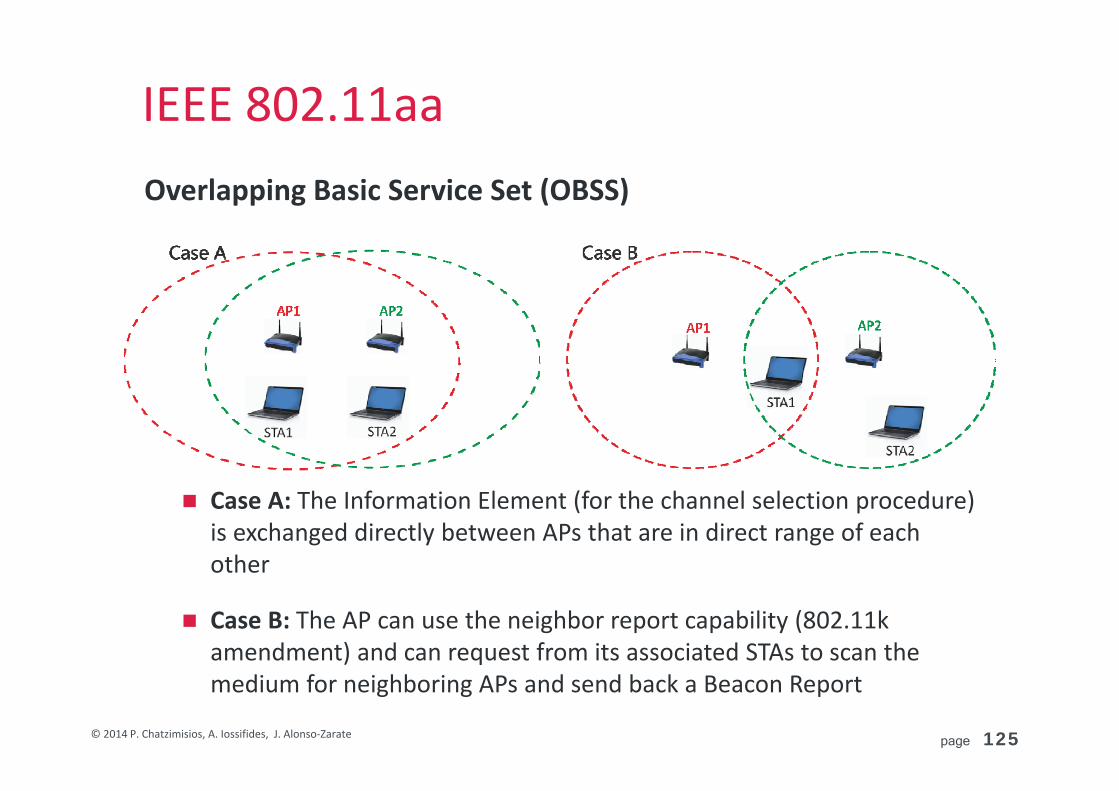
IEEE 802.11aaOverlapping Basic Service Set (OBSS)
Case A: The Information Element (for the channel selection procedure) is exchanged directly between APs that are in direct range of each other
Case B: The AP can use the neighbor report capability (802.11k amendment) and can request from its associated STAs to scan the medium for neighboring APs and send back a Beacon Report
page 126© 2014 P. Chatzimisios, A. Iossifides, J. Alonso‐Zarate
IEEE 802.11aaOverlapping Basic Service Set (OBSS)
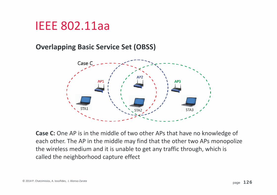
Case C: One AP is in the middle of two other APs that have no knowledge of each other. The AP in the middle may find that the other two APs monopolize the wireless medium and it is unable to get any traffic through, which is called the neighborhood capture effect
page 127© 2014 P. Chatzimisios, A. Iossifides, J. Alonso‐Zarate
IEEE 802.11aePrioritization of Management Frames (2012)
Problem All management frames are transmitted with the highest priority and
this can interfere with the transmission of multimedia traffic
Solutions A QoS management frame (QMF) service provides a mapping between
the management frame types/subtypes and the EDCA Access Categories. All management frames are sent in an AC as defined by the current QMF policy
A signaling protocol for the exchange of frame prioritization policies that depends on the network type. In infrastructure, the AP defines the QMF policy for the whole BSS. In mesh, the QMF policy can be disseminated using either existing frames (e.g., beacons) or a mesh station defines the QMF policy with another mesh station on a per‐link basis
page 128© 2014 P. Chatzimisios, A. Iossifides, J. Alonso‐Zarate
IEEE 802.11afTelevision White Spaces (TVWS) Operation (2014) Scope: It defines international specifications for spectrum sharing
among unlicensed White Space Devices (WSDs) and licensed services in the TV white space (TVWS) that exists in the broadcast TV operating frequencies known (ranging from 470–790 MHz in Europe and non‐continuous 54–698 MHz in USA)
Characteristics: Spectrum sharing is conducted through the regulation of unlicensed
WSDs by a Geolocation DataBase (GDB), the implementation of which differs among regulatory domains
The physical layer is based on 802.11ac Through the Channel Availability Query (CAQ) procedure, STAs obtain
the available radio frequencies that allow operation in their location in the form of a White Space Map (WSM)
A two‐message procedure termed Network channel control (NCC) controls the frequency usage in the TVWS band
page 129© 2014 P. Chatzimisios, A. Iossifides, J. Alonso‐Zarate
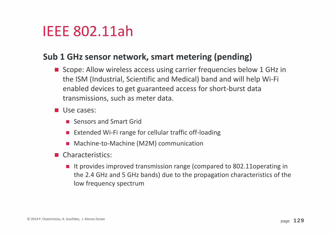
IEEE 802.11ahSub 1 GHz sensor network, smart metering (pending) Scope: Allow wireless access using carrier frequencies below 1 GHz in
the ISM (Industrial, Scientific and Medical) band and will help Wi‐Fi enabled devices to get guaranteed access for short‐burst data transmissions, such as meter data.
Use cases: Sensors and Smart Grid Extended Wi‐Fi range for cellular traffic off‐loading Machine‐to‐Machine (M2M) communication
Characteristics: It provides improved transmission range (compared to 802.11operating in
the 2.4 GHz and 5 GHz bands) due to the propagation characteristics of the low frequency spectrum
page 130© 2014 P. Chatzimisios, A. Iossifides, J. Alonso‐Zarate
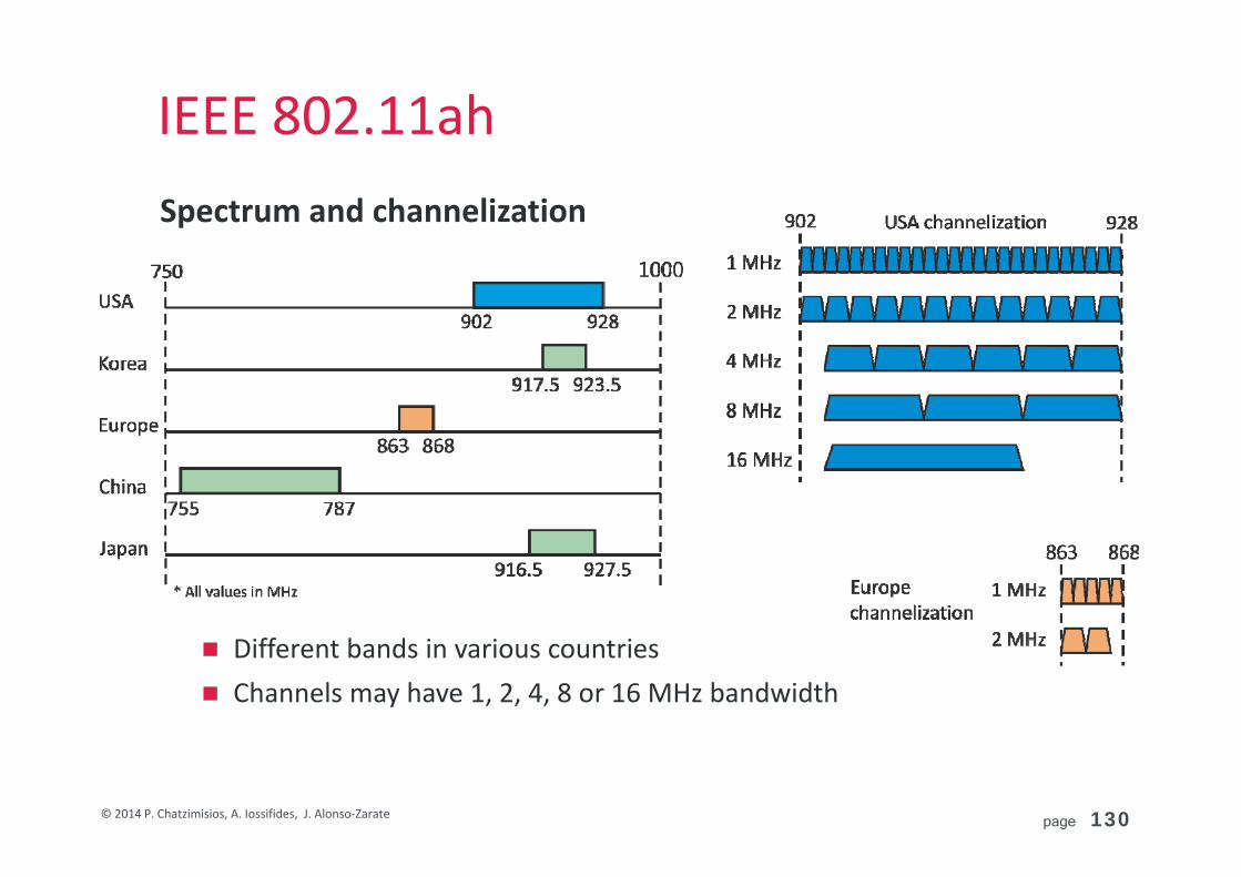
IEEE 802.11ahSpectrum and channelization
Different bands in various countries Channels may have 1, 2, 4, 8 or 16 MHz bandwidth

page 131© 2014 P. Chatzimisios, A. Iossifides, J. Alonso‐Zarate
IEEE 802.11ahOFDM based on 802.11ac 10 times downclocking from 312.5 to 31.25 KHz subcarrier distance. Symbol duration is 10 times greater (40 μs) with normal (8 μs) or
shortened (4 μs) GI. Iden cal number of subcarriers for 160→16 MHz, 80 → 8 MHz, 20 → 2
MHz, and 1 ΜΗz 2x lower than 2 ΜΗz.
Modulation and coding based on 802.11ac Modulation ranges from BPSK to 256 QAM Coding can be convolutional or LDPC 11 MCS schemes are defined
MU‐MIMO Equivalent to 802.11ac options with 4 a max of 4 spatial streams.

page 132© 2014 P. Chatzimisios, A. Iossifides, J. Alonso‐Zarate
IEEE 802.11ah
Shortened GI results in 10/9 increase of the data rate.Data rate is further multiplied by the number of SS. Max data rate can reach ~346 Mbps.MCS 10 includes repetition of data (as defined in MCS 0) in order to enhance coverage.
MCS Modulation, Coding 1 MHz 2 MHz 4 MHz 8 MHz 16
MHz
0 BPSK, 1/2 0.3 0.65 1.35 2.93 5.85
1 QPSK, 1/2 0.6 1.30 2.70 5.85 11.70
2 QPSK, 3/4 0.6 1.95 4.05 8.78 17.55
3 16QAM, 1/2 1.2 2.60 5.40 11.70 23.40
4 16QAM, 3/4 1.8 3.90 8.10 17.55 35.10
5 64QAM, 2/3 2.4 5.20 10.80 23.40 46.80
6 64QAM, 3/4 2.7 5.85 12.15 26.33 52.65
7 64QAM, 5/6 3.0 6.50 13.50 29.25 58.50
8 256QAM, 3/4 3.6 7.80 16.20 35.10 70.20
9 256QAM, 5/6 4.0 ‐ 18.00 39.00 78.00
10 BPSK, 1/4 0.15 ‐ ‐ ‐ ‐
Example data rates (Mbps) of available MCS with 1 SS and normal GI

page 133© 2014 P. Chatzimisios, A. Iossifides, J. Alonso‐Zarate
IEEE 802.11aq/axIEEE 802.11aq ‐ Pre‐association Discovery (pending)
Scope: Will enable pre‐association discovery of services by extending some of the mechanisms in 802.11u that enabled device discovery to further discover the services running on a device or provided by a network. The idea is to advertise their existence and enable delivery of information that describes them prior to association by stations operating on IEEE 802.11 wireless networks
IEEE 802.11ax ‐ High Efficiency WLAN (pending) Scope: As a successor to 802.11ac the scope is to enable at least one
mode of operation capable of supporting at least four times improvement in the average throughput per station (measured at the MAC data service access point) in a dense deployment scenario, while maintaining or improving the power efficiency per station. Operation will be defined in frequency bands between 1 GHz and 6 GHz.

page 134© 2014 P. Chatzimisios, A. Iossifides, J. Alonso‐Zarate
Challenges and open issues

page 135© 2014 P. Chatzimisios, A. Iossifides, J. Alonso‐Zarate
Source: Wireless Broadband Alliance (WBA), Industry Report 2013
Recall…WiFi Can Help Boost Capacity

page 136© 2014 P. Chatzimisios, A. Iossifides, J. Alonso‐Zarate
Future VHT Applications

page 137© 2014 P. Chatzimisios, A. Iossifides, J. Alonso‐Zarate
But also other requirements…
© http://postscapes.com/internet-of-things-examples/
Wearable devices for eHealth, fitness, gaming, augmented reality, etc.
Connected Homes (with many devices)

page 138© 2014 P. Chatzimisios, A. Iossifides, J. Alonso‐Zarate
Some Challenges Ahead
page 139© 2014 P. Chatzimisios, A. Iossifides, J. Alonso‐Zarate
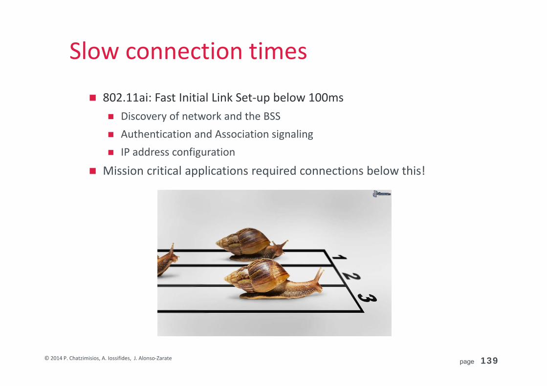
Slow connection times
802.11ai: Fast Initial Link Set‐up below 100ms Discovery of network and the BSS Authentication and Association signaling IP address configuration
Mission critical applications required connections below this!

page 140© 2014 P. Chatzimisios, A. Iossifides, J. Alonso‐Zarate
Congestion
Still using CSMA!
page 141© 2014 P. Chatzimisios, A. Iossifides, J. Alonso‐Zarate
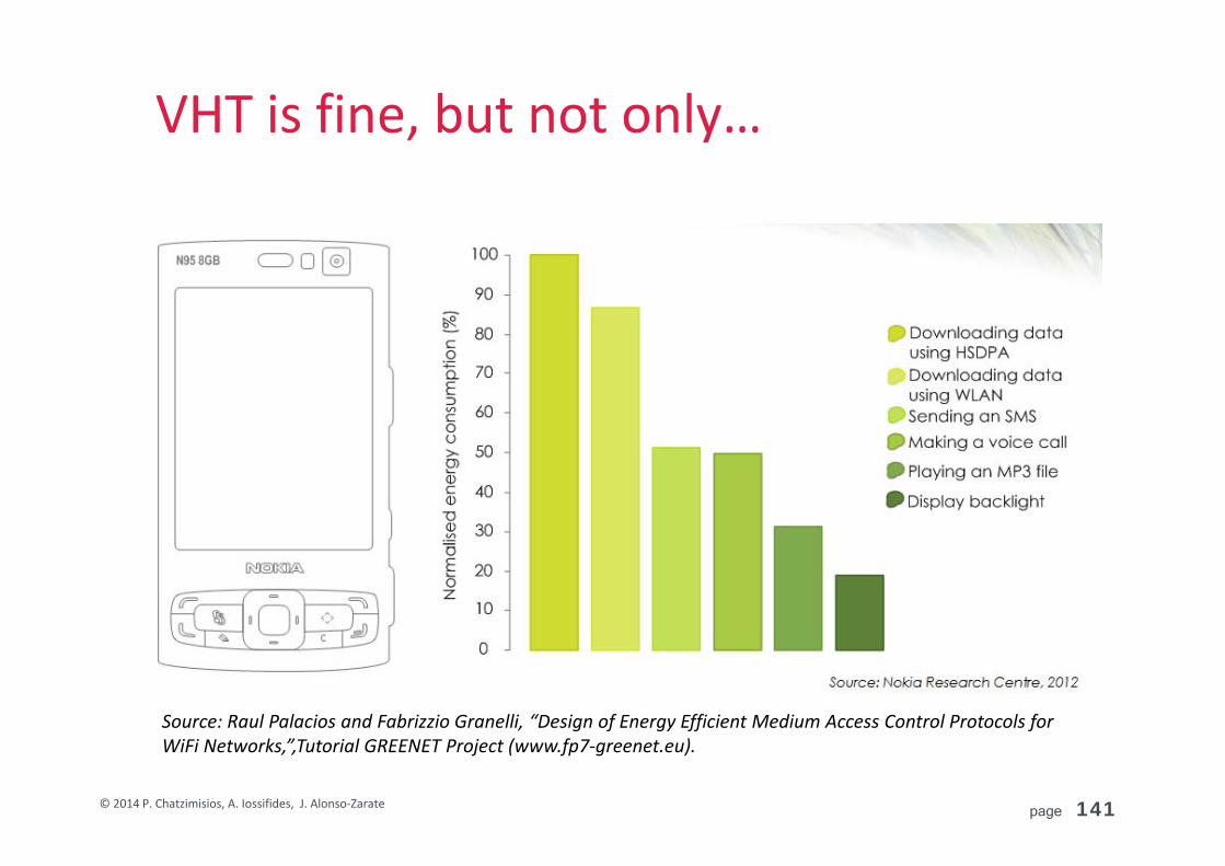
VHT is fine, but not only…
Source: Raul Palacios and Fabrizzio Granelli, “Design of Energy Efficient Medium Access Control Protocols for WiFi Networks,”,Tutorial GREENET Project (www.fp7‐greenet.eu).

page 142© 2014 P. Chatzimisios, A. Iossifides, J. Alonso‐Zarate
Even with coolest tech…

page 143© 2014 P. Chatzimisios, A. Iossifides, J. Alonso‐Zarate
Energy Efficiency Comes Next Improve the Power Saving Mechanism (PSM)
Inactive and in Active Periods Consider Transition Times and Consumption: ON‐OFF transitions Consider Exploitation of TXOP to apply Energy Efficient Periods R. Palacios, F. Granelli, D. Gajic, C. Liss, and D. Kliazovich, “An Energy‐efficient Point Coordination
Function Using Bidirectional Transmissions of Fixed Duration for Infrastructure IEEE 802.11 WLANs,” in IEEE ICC 2013, 9–13 Jun. 2013, pp. 1036–1041.
R. Palacios, F. Granelli, D. Kliazovich, L. Alonso, and J. Alonso‐Zarate, “An Energy Efficient Distributed Coordination Function Using Bidirectional Transmissions and Sleep Periods for IEEE 802.11 WLANs,” in IEEE GLOBECOM 2013, 9–13 Dec. 2013, pp. 1641–1647.
R. Palacios, E. M. B. Larbaa, J. Alonso‐Zarate, and F. Granelli, “Performance Analysis of Energy‐Efficient MAC Protocols using Bidirectional Transmissions and Sleep Periods in IEEE 802.11 WLANs”, in IEEE GLOBECOM 2014, 8‐12 Dec. 2014. CQRM 4: Resource Allocation in Wireless Networks from Thu, December 11, 2014 14:00 until 15:45 (3rd paper) in 602 (17.5 min.)
Consider TXOP and Duty Cycling to execute innovative approaches, such as Network Coding (longer packets) CQRM I‐1: Network Coding from Thu, December 11, 2014 10:30 until 12:15 (3rd paper) in INTERACTIVESESSIONROOM (17.5 min.)

page 144© 2014 P. Chatzimisios, A. Iossifides, J. Alonso‐Zarate
Security
Protection against attacks (e.g. DoS)
Data Interception Privacy and Confidentiality
Wireless Intruders
MisconfiguredPublic APs
Misbehaving users
Suggested Reading: http://www.esecurityplanet.com/views/article.php/3869221/Top‐Ten‐WiFi‐Security‐Threats.htm

page 145© 2014 P. Chatzimisios, A. Iossifides, J. Alonso‐Zarate
Seamless Operation in 5G vision
Source: https://www.qualcomm.com/media/documents/files/wireless-networks-wi-fi-evolution.pdf
ANDSF: Access Network Discovery and Selection Function defined in 3GPPP

page 146© 2014 P. Chatzimisios, A. Iossifides, J. Alonso‐Zarate
MultiRAT Integration

page 147© 2014 P. Chatzimisios, A. Iossifides, J. Alonso‐Zarate
Competitors?

page 148© 2014 P. Chatzimisios, A. Iossifides, J. Alonso‐Zarate
In Summary…. Increasing amounts of data Tighter QoS Requirements (latency, delay, jitter, etc.) Need to offload cellular networks Increasing number of simultaneous users Still worse with the arrival of the IoT Trend towards use of smaller cells (large ranges not needed) Everything is about providing
VHT High Energy Efficiency Massive Access in dense Areas Secured Communications

page 149© 2014 P. Chatzimisios, A. Iossifides, J. Alonso‐Zarate
Q & AThank you very much for the careful listening!
Questions?
page 150© 2014 P. Chatzimisios, A. Iossifides, J. Alonso‐Zarate
Additional

page 151© 2014 P. Chatzimisios, A. Iossifides, J. Alonso‐Zarate
Complementary Golay sequencesCorrelation with Golaysequences Ga128 and Gb128 is performed in parallel with a single, very simple and fast circuit.
AC(Ga128)