pas002 troubleshooting guide for 2016 ul 325 … · has a primary side ... rating for each device...
TRANSCRIPT

LiftMaster845 Larch AvenueElmhurst, IL 60126-1196
LA500U
LA400U
LA412U
CSW24U
CSL24U
RSL12U
RSW12U
CSW200U
SL3000U
SL585U
SL595U
TROUBLESHOOTING GUIDEM
odel
s for 2016 UL 325 Compliant Gate Operators

1
TABLE OF CONTENTS
SAFETY 1SAFETY SYMBOL AND SIGNAL WORD REVIEW ..................................1
BEFORE YOU BEGIN 22016 UL COMPLIANT GATE OPERATORS .............................................2
BASIC TROUBLESHOOTING 3MULTI-METERS .....................................................................................3TRANSFORMERS ...................................................................................4RELAYS .................................................................................................5EXPANSION BOARD SWITCH SETTINGS ..............................................5CAPACITOR (FOR AC OPERATORS) ......................................................6DC MOTORS ..........................................................................................7AC MOTORS ..........................................................................................8ERASE MEMORY ...................................................................................9
DIAGNOSTIC CODES 10
SOLAR 16SOLAR TROUBLESHOOTING ...............................................................1624V APPLICATIONS .............................................................................1712V APPLICATIONS .............................................................................18
POWER 19MODELS CSW200U AND SL3000U .....................................................19MODELS SL585U AND SL595U (SINGLE PHASE) ..............................20MODELS SL585U AND SL595U (THREE PHASE) ................................21MODEL LA412U ...................................................................................22MODEL LA400U ...................................................................................23MODEL LA500U ...................................................................................24MODELS CSL24U AND CSW24U .........................................................25MODELS RSL12U AND RSW12U ........................................................26
MYQ® 27
FREQUENTLY ASKED QUESTIONS ......................................................27TROUBLESHOOTING MyQ® ...................................................................................................................29
MyQ® ACCOUNT ISSUES .....................................................................30MyQ® ACCOUNT ISSUES .....................................................................31MyQ® ERROR CODES ..........................................................................32INCOMPATIBLE ROUTER AND SWITCH ..............................................34
MECHANICAL
ELECTRICAL
SAFETY
SAFETY SYMBOL AND SIGNAL WORD REVIEW When you see these Safety Symbols and Signal Words on the following pages, they will alert you to the possibility of Serious Injury or Death if you do not comply with the warnings that accompany them. The hazard may come from something mechanical or from electric shock. Read the warnings carefully.
When you see this Signal Word on the following pages, it will alert you to the possibility of damage to your gate and/or the gate operator if you do not comply with the cautionary statements that accompany it. Read them carefully.
IMPORTANT NOTE:• BEFORE attempting to install, operate or maintain the operator, you must read and fully
understand the manual provided with your operator and follow all safety instructions.• DO NOT attempt repair or service of your gate operator unless you are an Authorized
Service Technician.

2
2016 UL COMPLIANT GATE OPERATORS
New UL 325 standards for vehicular gate operators go into effect in January of 2016. The new standard will require gate operators to monitor for fault conditions of external entrapment devices. LiftMaster has not only updated their line of gate operators to meet the new UL 325 standard, they have also taken the opportunity to add a common user interface and common feature sets across the line to increase performance, safety and accessibility. All LiftMaster UL compliant gate operators will come with external monitored retro-reflective photoelectric sensors (model LMRRU).
These operators contain an inherent (internal) entrapment protection system and REQUIRE the addition of an external monitored entrapment protection system (non-contact photoelectric sensor or contact edge sensor) for EACH entrapment zone prior to gate movement. A monitored device sends a pulsed signal to the operator so the operator is aware of the device. If the operator does not receive the signal from the device it will not run.
An entrapment zone is every location or point of contact where a person can become entrapped between a moving gate and a stationary object. Your application may contain one or many entrapment zones. Property owners are obligated to test entrapment protection devices monthly. Use only LiftMaster approved entrapment protection devices.
BEFORE YOU BEGIN
LiftMaster Monitored Retro-Reflective Photoelectric Sensors (Model LMRRU)
3
BASIC TROUBLESHOOTING
MULTI-METERS
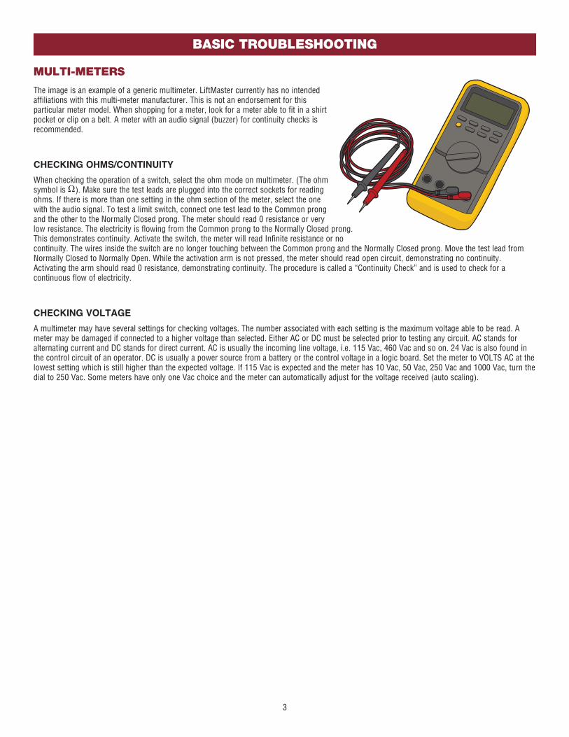
The image is an example of a generic multimeter. LiftMaster currently has no intended affiliations with this multi-meter manufacturer. This is not an endorsement for this particular meter model. When shopping for a meter, look for a meter able to fit in a shirt pocket or clip on a belt. A meter with an audio signal (buzzer) for continuity checks is recommended.
CHECKING OHMS/CONTINUITY
When checking the operation of a switch, select the ohm mode on multimeter. (The ohm symbol is ). Make sure the test leads are plugged into the correct sockets for reading ohms. If there is more than one setting in the ohm section of the meter, select the one with the audio signal. To test a limit switch, connect one test lead to the Common prong and the other to the Normally Closed prong. The meter should read 0 resistance or very low resistance. The electricity is flowing from the Common prong to the Normally Closed prong. This demonstrates continuity. Activate the switch, the meter will read Infinite resistance or no continuity. The wires inside the switch are no longer touching between the Common prong and the Normally Closed prong. Move the test lead from Normally Closed to Normally Open. While the activation arm is not pressed, the meter should read open circuit, demonstrating no continuity. Activating the arm should read 0 resistance, demonstrating continuity. The procedure is called a “Continuity Check” and is used to check for a continuous flow of electricity.
CHECKING VOLTAGE
A multimeter may have several settings for checking voltages. The number associated with each setting is the maximum voltage able to be read. A meter may be damaged if connected to a higher voltage than selected. Either AC or DC must be selected prior to testing any circuit. AC stands for alternating current and DC stands for direct current. AC is usually the incoming line voltage, i.e. 115 Vac, 460 Vac and so on. 24 Vac is also found in the control circuit of an operator. DC is usually a power source from a battery or the control voltage in a logic board. Set the meter to VOLTS AC at the lowest setting which is still higher than the expected voltage. If 115 Vac is expected and the meter has 10 Vac, 50 Vac, 250 Vac and 1000 Vac, turn the dial to 250 Vac. Some meters have only one Vac choice and the meter can automatically adjust for the voltage received (auto scaling).

4
BASIC TROUBLESHOOTING
TRANSFORMERS
Transformers are used to change incoming voltage to a different outgoing voltage. A transformer has a primary side (incoming voltage) and a secondary side (outgoing voltage). The primary side connects to wires from the main power source and the secondary side outputs the new voltage created. In commercial gate operators, the secondary side is generally 24 Vac. Read the markings on the transformer to determine the primary and secondary voltages. Transformers are rated in VOLT Amps (VA). A transformer can only pass the rated amount of electricity from the main power to the secondary side. Be careful not to overload the transformer. Verify the amperage rating on all devices connected to the 24 Vac side of the transformer including devices attached to the control board. Multiply the Amperage rating for each device by the voltage needed to run the
device.
EXAMPLE FOR CALCULATING AMPERAGE DRAW
Below is an example of text for a label that could be placed on accessory devices:
Output Rating…5 AMPS 28VAC or DC Max
Power…24VAC @ 30ma
The “Power” rating is required. The transformer’s secondary side is 24 VAC and the transformer is rated for 20VA. The example accessory above uses 30 milli-amps, which is .03 Amps. Multiply the volts being used (24V) and the amps (.03A) to get the VOLT Amps (VA) used by the accessory (24Vx0.03A=0.72VA). That leaves (20-0.72=) 19.28VA left for other accessories (photoelectric sensors, loop detectors, etc). Once the total VA exceeds 20VA, the operator may experience failures. For operator setups requiring multiple accessories, calculate total VA draw and upgrade the transformer if necessary (40VA transformers or greater are available). The output rating is how much electricity the accessory is able to have pass through it. This number is useful when determining if an accessory will properly function long term with the operator. The output rating has nothing to do with the required amount of electricity to make the accessory function.
COM
120240
COM
120240
24 Vac
TYPE OF TRANSFORMERS MODELS
Plug-in Transformer LA400U, RSL12U, RSW12U
Toroid Transformer LA500U, CSL24U, CSW24U
Block Transformer CSW200U, SL3000U, SL585U, SL595U
(Example: Block Transformer)

5
BASIC TROUBLESHOOTING
RELAYS
EXPANSION BOARD RELAYS
In gate operators, relays are often used to either control certain operator functions or activate/deactivate ancillary devices such as heaters or lights. When electricity is applied to a relay coil, it energizes a magnet and will close a Normally Open switch or open a Normally Closed switch. A relay typically has prongs labeled COMM , NO, NC, and two prongs to power the relay coil. Relays are available with different coil voltages and contact options. LiftMaster’s line of gate operators primarily use double pole/double throw relays. The auxiliary relays are single pole, double throw. A pole is another name for a switch. Double pole is two separate switches being turned on or off by the same activation coil (two separate Comms, NCs and NOs). Double throw means there are two positions for the output (NO and NC).
The 2 Auxiliary Relays on the expansion board can be set to activate in different conditions based on how you set the 3 switches for each relay. They can be set to activate any time the gate is open or closed or when the gate is in motion. In one setting you can trip the relay 3 seconds before the gate begins to move and while the gate is in motion. You can set the relay to activate if the gate is forced off the closed limit position. One setting for Aux Relay 1 uses the LEDs for the Open, Close, and Stop inputs to display how many cycles (to the nearest 1000) the operator has performed. The Auxiliary relays can also be used in conjunction with a barrier arm operator for the SAMS or tandem function.
EXPANSION BOARD SWITCH SETTINGS
• The Quick Close feature allows the gate to close without having to travel to the full open position. When active, the operator monitors the Interrupt Loop and Close Eyes inputs and once the vehicle clears these devices the gate will reverse and Close.
• When the AC Fail Open switch is selected, the operator will move the gate to the Open position if AC Power is lost. If the switch is set for the Battery option, the operator will run on the battery until the battery drops below a certain voltage. At that point, the gate will either open or close depending on how you set the Low Battery switch on the main control board. NOTE: The AC Fail Open switch is not functional for AC operators.
• The Exit Fail switch sets the operator to either open or remain closed in the event of an internal detector failure (loop short or open).
• The Anti-Tailgate switch alters the way the Interrupt Loop affects gate operation. When the switch is on, the gate pauses if the gate is closing and the interrupt loop is activated. The gate will stay paused until the vehicles backs off the loop, then continue closing.
SBC
OPN
CLS
STP
COM
EYEONLY
EYE/EDGE
EYE/EDGE
COM
1
2
3
OP
EN
CLO
SE
TO
MA
INB
OA
RD
POWER
SBC
OPN
CLS
STP
COM
EYEONLY
EYE/EDGE
EYE/EDGE
COM
1
2
3
OP
EN
CLO
SE
TO
MA
INB
OA
RD
POWER
RELAY WIRING EXAMPLERELAYS ON THE EXPANSION BOARD
+–
Traffic Light
Class 2 Power Source(42 Vdc [34 Vac], 5 A maximum)
6
BASIC TROUBLESHOOTING
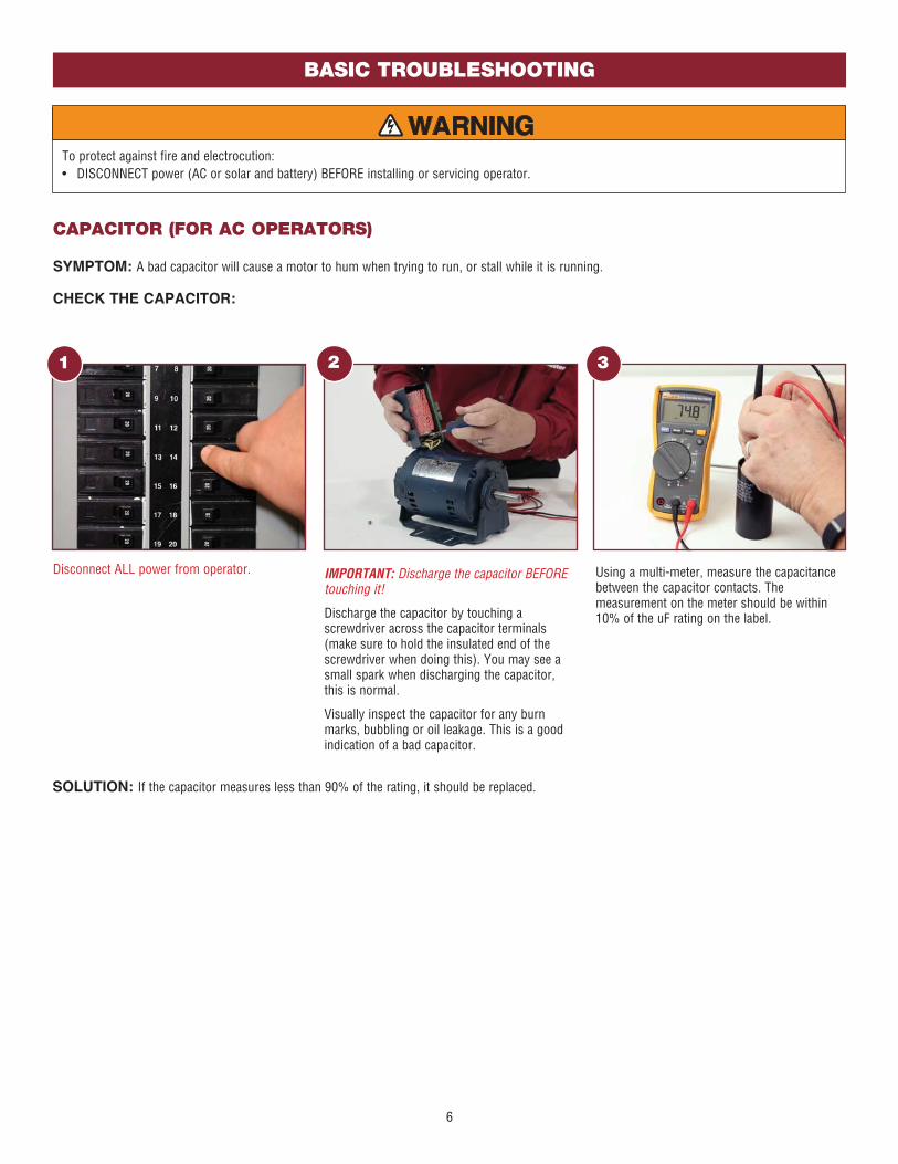
CAPACITOR (FOR AC OPERATORS)
SYMPTOM: A bad capacitor will cause a motor to hum when trying to run, or stall while it is running.
CHECK THE CAPACITOR:
To protect against fire and electrocution:• DISCONNECT power (AC or solar and battery) BEFORE installing or servicing operator.
1
Disconnect ALL power from operator.
2 3
IMPORTANT: Discharge the capacitor BEFORE touching it!
Discharge the capacitor by touching a screwdriver across the capacitor terminals (make sure to hold the insulated end of the screwdriver when doing this). You may see a small spark when discharging the capacitor, this is normal.
Visually inspect the capacitor for any burn marks, bubbling or oil leakage. This is a good indication of a bad capacitor.
Using a multi-meter, measure the capacitance between the capacitor contacts. The measurement on the meter should be within 10% of the uF rating on the label.
SOLUTION: If the capacitor measures less than 90% of the rating, it should be replaced.
7
DIAGNOSTICS
1
2
Jumper Cables
DIAGNOSTICS
1
2
Jumper Cables
BATTERIES
MOTORMOTOR
BASIC TROUBLESHOOTING
To protect against fire and electrocution:• DISCONNECT power (AC or solar and battery) BEFORE installing or servicing operator.
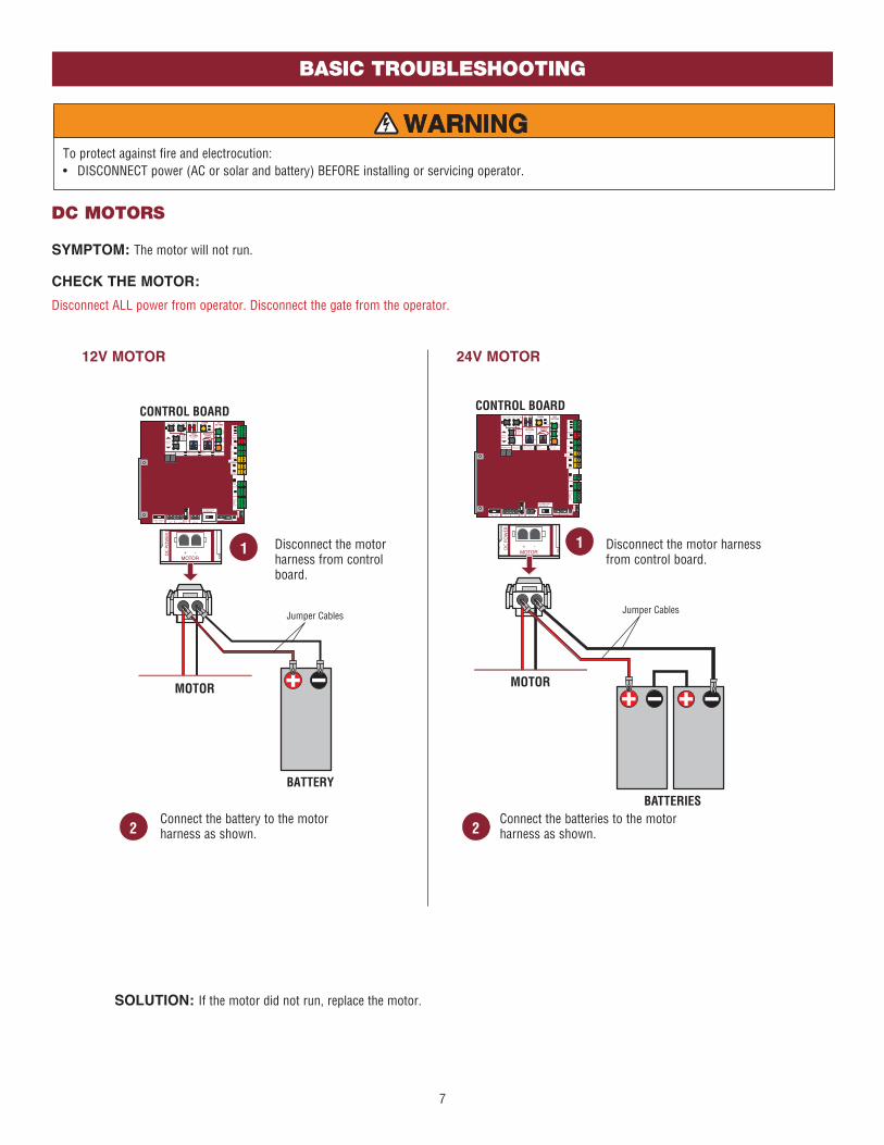
DC MOTORS
SYMPTOM: The motor will not run.
CHECK THE MOTOR:
Disconnect ALL power from operator. Disconnect the gate from the operator.
Disconnect the motor harness from control board.
Connect the battery to the motor harness as shown.
SOLUTION: If the motor did not run, replace the motor.
12V MOTOR 24V MOTOR
Disconnect the motor harness from control board.
Connect the batteries to the motor harness as shown.

8
BASIC TROUBLESHOOTING
To protect against fire and electrocution:• DISCONNECT power (AC or solar and battery) BEFORE installing or servicing operator.
AC MOTORS
SYMPTOM: The motor will not run.
CHECK THE MOTOR:
Disconnect ALL power from operator. Disconnect the gate from the operator. Unplug the motor harness from the board and measure the resistance of the motor. Refer to illustrations.
SOLUTION: If the motor measured too much resistance or zero resistance, replace the motor.
12
11
10
9
8
7
6
5
4
3
2
1
Blue
YellowYellow/Black
Orange
White
Red
Purple
Yellow/Black
Purple
Black13
1012
2
456
789
11
Gray
Gray
TH
ER
MA
L S
WIT
CH
RU
N 1
RU
N 2
STA
RT
RUN 1 = 600 ohms or less
RUN 2 = 600 ohms or less
START = 50k ohms or greater
THERMAL SWITCH = 0 ohms
Measure resistance between:
Unplug motor harness
from power board
BEFORE measuring.
12
13
14
15
11
10
9
8
7
6
5
4
3
2
1
Blue
Yellow
Yellow/Black
Orange
Brown
Gray
White
Red
Purple
Purple
Yellow/Black
Purple
Purple
Purple
Black
13
15 13
2
456
789
1011
14
12
Resistance should be
600 ohms or less
15 to 7
14 to 8
12 to 6
11 to 6
9 to 5
Measure resistance between:
Unplug motor harness
from power board
BEFORE measuring.
TH
ER
MA
L S
WIT
CH
There should be continuity
between 1 and 4 (Thermal Switch)
MODELS CSW200U & SL3000
MOTOR
ID
J14
MOTOR RED MOTOR BLUE
J11
J7 SWITCH
TRANSFORMERJ5
J3
COMM
120VAC
MOTOR
WHITEJ2
J1INPUT
NEUTRAL
OUTLETJ12
J6 BLACK
WHITE
INPUT
HOTJ4
J10
MOTOR
CONTROL
CURRENT
SENSOR
J8
J16
SWITCH
J17
J20
J13
J19
J21
J18
Red
Wh
ite
Black
Red and Black
Black and White
Red and White
Resistance should be 600 ohms or less.
Measure resistance between:
Motor shaft should
turn easily.

9
BASIC TROUBLESHOOTING
ERASE MEMORY
ERASE ALL REMOTE CONTROLS
1. Remove the entrapment protection device wires from the terminal block.
2. Press and release the OPEN LEFT and OPEN RIGHT buttons simultaneously. The handing direction LED will remain solid. The other direction LED will begin flashing (entering setup mode).
3. Press the OPEN LEFT and OPEN RIGHT buttons simultaneously to exit.
ERASE LIMITS (DC OPERATORS)
1. To erase the limits, press and hold the SET OPEN and SET CLOSE buttons simultaneously (5 seconds) until both the SET OPEN and SET CLOSE LEDs blink rapidly and the operator beeps.
2. Release the buttons and the SET OPEN and SET CLOSE LEDs will blink slowly indicating the limits will need to be set.
Any remaining entrapment protection devices will automatically relearned and any disconnected entrapment protection devices will be unlearned. A minimum of ONE monitored entrapment protection device is required to operate the gate.
TO REMOVE AND ERASE MONITORED ENTRAPMENT PROTECTION DEVICES (DC OPERATORS)
1. Remove the entrapment protection device wires from the terminal block.
2. Press and release the SET OPEN and SET CLOSE buttons simultaneously. The SET OPEN and SET CLOSE LEDs will turn on (entering learn limit mode).
3. Press and release both SET OPEN and SET CLOSE buttons again to turn off the SET OPEN and SET CLOSE LEDs (exiting learn limit mode).
Any remaining entrapment protection devices will automatically relearned and any disconnected entrapment protection devices will be unlearned. A minimum of ONE monitored entrapment protection device is required to operate the gate.
1. Press and release the LEARN button (operator will beep and green XMITTER LED will light).
2. Press and hold the LEARN button again until the green XMITTER LED flashes and then release the button (approximately 6 seconds). All remote control codes are now erased.
TO REMOVE AND ERASE ALL MONITORED ENTRAPMENT PROTECTION DEVICES (AC OPERATORS)
ERASE HANDING (AC OPERATORS)
1. To erase the limits, press and hold the OPEN LEFT and OPEN RIGHT buttons simultaneously (5 seconds) until both the OPEN LEFT and OPEN RIGHT LEDs blink rapidly and the operator beeps.
2. Release the buttons and the OPEN LEFT and OPEN RIGHT will blink slowly indicating the handing will need to be set.

10
DIAGNOSTIC CODES
To protect against fire and electrocution:• DISCONNECT power (AC or solar and battery) BEFORE installing or
servicing operator.
For continued protection against fire:• Replace ONLY with fuse of same type and rating.
TO VIEW THE CODESThe codes will show on the diagnostic display.
TO SCROLL THROUGH THE SAVED CODES
A SECOND LATER....
The operator will only keep track of up to 20 codes, then will start saving over the oldest codes as new codes occur.
The operator will show the code sequence number followed by the code number:
NOTE: When cycling or disconnecting power (ac/dc) to the control board, it is recommended that you unplug the J15 plug.
CODE NUMBER
The second number shown after the code sequence number is the code itself (31-99, example" "31"). Refer to the chart on the following page for an explanation of each code.
CODE SEQUENCE NUMBER
The first number shown is the most recent code (example: "01"). The display will show the sequence of codes that occurred starting with "01" and going up to code "20".
TO EXITPress and release the STOP button to exit. The display will also time out after two minutes of inactivity.
TO RESET THE CODE HISTORY1. Press and hold the STOP button for six seconds. The display will
show "Er" then "CL" alternately for six seconds.2. Release the STOP button. The code history has now been reset and
the display will show "- -" until a new code occurs.3. Press and release the STOP button to exit.
DIAGNOSTICS DISPLAYOPEN, CLOSE, & STOP BUTTONS
DIAGNOSTIC CODES
Press and hold the STOP button...
...then press and hold the CLOSE button...
...then press and hold the OPEN button until "Er" shows on the display.
Press the OPEN button to cycle to the most recent code ("01").
Press the CLOSE button to cycle to the oldest code (up to "20").

11
Some codes are saved in the code history and some are not. If a code is not saved it will briefly appear on the display as it occurs, then disappear. When servicing of the operator is complete, erase the code history by pressing the STOP button until the display flashes “Er” then “CL” (about 6 seconds). When the codes have been erased the display will show “_ _”.
Code Meaning Symptom Solution Saved
LIFT
MAS
TER
SYST
EM
31The main control board has experienced an internal failure.
Gate operator will not run. Disconnect all power, wait 15 seconds, then reconnect power (reboot). If issue continues, replace main control board.
NO
32 Linear Drive Disengaged (Operator 1)
Gate operator will not run and the gate moves back and forth easily.
Disengage, then re-engage operator. Check wiring and connections. YES
33 Linear Drive Disengaged (Operator 2)
34
The operator is not receiving information from the Absolute Position Encoder (APE).
The operator will run for a second or two, then stop (there are no obstructions). The diagnostic display shows 34.
• Check the APE sensor for a blocked diode from dust or debris. Use compressed air to clean the area.
• Check the APE wire harness connections. A wire may be loose or disconnected from the harness.
• Replace the APE assembly and wire harness if necessary.
TEST: Attempt to run the operator.
YES
35 Max-Run-Time Exceeded Error The gate stops short of the programmed limit.
Check for an obstruction, then reprogram the limits. YES
36
Product ID Error If product ID is not present or damaged while the gate is powered it will continue to run while showing code 36. If power is lost while product ID is damaged or broken it will not run and will also show code 36. If the board was used in a different type of operator it code 36 would show as well (example board out of swing to a slide).
Was the control board just replaced? If so, erase limits, then set limits again. If not, disconnect all power, wait 15 seconds, then reconnect power before changing product ID harness.
YES
37
Product ID Failure If product ID is not present or damaged while gate is powered it will continue to run while showing code 37. If power is lost while product ID is damaged or broken it will not run and will also show code 37. The operator will also not be able to set limits.
Unplug product ID harness then plug back in. Disconnect all power, wait 15 seconds, then reconnect power before replacing product ID harness.
YES
38
Hard Stop Limit (Operator 1), the limit is set too close to a hard stop and the gate is stopping on the hard stop instead of the limit.
The gate will reverse intermittently. The operator may wind up a lot of tension on the chain and flex the chassis. For dual gate installations the gates may not move in sync. This could cause a problem later on if left (nuisance reversals).
Reprogram the limits so they are not close to a hard stop.
TEST: Run the operator and check for code 38 on the diagnostic display. NO
39
Hard Stop Limit (Operator 2), the limit is set too close to a hard stop and the gate is stopping on the hard stop instead of the limit.
40
Battery overvoltage The operator runs faster than normal and the diagnostic display shows Code 40.
Too much voltage on the battery. Check harness. Make sure you are using the recommended batteries for the operator. Check the battery voltage and battery harness.
TEST: After checking the batteries, check for code 40 on the diagnostic display.
YES
DIAGNOSTIC CODES

12
Code Meaning Symptom Solution Saved
LIFT
MAS
TER
SYST
EM
41
Battery overcurrent Code 41 will show up on the diagnostic display. There will possibly be low battery voltage (the LOW BATT LED will be on).
Possible short of the battery charge harness. Check harness. Make sure the recommended battery(ies) are being used. Make sure you do NOT have a 12V battery on a 24V system. Check battery fuse.
TEST: After checking the batteries, check for code 41 on the diagnostic display.
YES
42
No battery at boot up Operator will run and the diagnostic display will show Code 42 with power cycle or boot-up. The operator will not run on battery backup after power loss.
Check the battery connections at the main control board and at the battery terminals. Make sure the J15 plug is plugged into the board. Replace batteries if depleted to less than 20V on a 24V system or less than 10V on a 12V system. Make sure there is NOT a single 12V battery on a 24V system.
TEST: After checking the batteries, check for code 42 on the diagnostic display.
YES
INST
ALLE
D SY
STEM
43
Exit Loop Error Gate will lock in the open position or closed position (depending on the dip switch setting). The exit loop will not be functional and diagnostic display will show Code 43.
LiftMaster Plug-in Loop Detector only. Failure or missing loop. Check loop wiring throughout connection. May be a short in the loop, or an open connection in the loop.
YES
44
Shadow Loop Error All Operators: Gate will not close.
Models LA400U, LA412U, LA500U, RSW12U: Gate will not open.
45 Interrupt Loop Error Gate will not close.
46
Wireless edge battery low
The operator will beep 2 times with a command. Critically low battery will cause gate to latch open or closed depending on the board settings (Batt Fail switch settings on DC operator control board and Exit Fail switch setting on the AC operator expansion board).
Replace batteries in wireless edge.
YES
LIFT
MAS
TER
SYST
EM 47Fault detected in the power board.
Operator will not run. Replace the power board.YES
50
Run-Distance Error Gate will stop prior to reaching the desired limit setting.
DC Operators: Gate unbalance detected. Make sure the gate is installed on a level surface and not on an excessive grade.
YESAC Operators: The limits are less than the minimum requirement or longer than what was learned. Check limit positions and proper switch function. Run-distance can be re-learned by setting the handing again.
INFO
RMAT
IONA
L
51 Pass-point not detected (Operator 1)
Operator runs at a constant slow speed.
Check yellow pass-point wiring. If limits are not accurate, reprogram.
NO52 Pass-point not detected
(Operator 2)
53Brownout occurred Operator will run and show
code 53.AC/DC board supply dipped below allowable level. Review power supply and wiring. If rebooting, ensure enough time for discharge of power to force a fresh boot.
YES
54Wireless Second Operator Communication Error
Only the commanded operator will respond.
Check the second operator for power. If OFF, restore power and try to run the system. If powered, deactivate the wireless feature and then reprogram the second operator.
YES
Some codes are saved in the code history and some are not. If a code is not saved it will briefly appear on the display as it occurs, then disappear. When servicing of the operator is complete, erase the code history by pressing the STOP button until the display flashes “Er” then “CL” (about 6 seconds). When the codes have been erased the display will show “_ _”.
DIAGNOSTIC CODES

13
Code Meaning Symptom Solution Saved
LIFT
MAS
TER
SYST
EM
55 System AC Overvoltage Operator will not function and show code 55.
Check with the utility company. YES
56 System AC Undervoltage Operator will continue to run and show code 56.
Check wiring and wire gauge to operator. YES
57 Limit Error - Stuck Switch Operator will not run and show code 57. Check switch for proper operation. Check harness for shorts. Replace if defective. YES
58 Limit Error - Wrong Switch Operator will not run and show code 58. Check motor wiring. YES
59 Missing Power Board Operator will not run and show code 59. Check harness for shorts. Check for presence of power board. YES
EXTE
RNAL
ENT
RAPM
ENT
PROT
ECTI
ON
60
Minimum number of monitored entrapment protection devices (one) not installed.
The operator will not run and the EYES EDGE LEDs will flash on the main board and expansion board.
Make sure there is a monitored entrapment protection device installed and connected to the operator. NO
61CLOSE EYE/INTERRUPT held more than 3 minutes on main board
The operator will only move with constant pressure and will beep while moving
Check for alignment or obstruction. Check wired input on main control board. The photoelectric sensors may be installed too far apart.
YES62 CLOSE EDGE held more than 3 minutes on main board
63 OPEN EYE/EDGE held more than 3 minutes on main board
64CLOSE EYE/INTERRUPT held more than 3 minutes on expansion board
The operator will only move with constant pressure and will beep while moving
Check for alignment or obstruction. Check wired input on expansion board. The photoelectric sensors may be installed too far apart.
YES65CLOSE EYE/EDGE held more than 3 minutes on expansion board
66OPEN EYE/EDGE held more than 3 minutes on expansion board
67 Wireless edge triggered more than 3 minutes
Gate will not move. Check wired input for wiring issue, obstruction or damaged edge. YES
68
Wireless edge loss of monitoring
Gate will not move. Check wireless edge inputs. Confirm the transmitter and receiver are installed at the recommended locations and within the range specified. Confirm the transmitter battery is operational and installed securely. Check the receiver to main control board wiring harness for damage and make sure the connector is fully seated.
YES
69Wireless edge triggered Gate reverses to the opposite direction. If an obstruction occurred, no action required. If
an obstruction did NOT occur, check inputs and wiring.
NO
DIAGNOSTIC CODES
Some codes are saved in the code history and some are not. If a code is not saved it will briefly appear on the display as it occurs, then disappear. When servicing of the operator is complete, erase the code history by pressing the STOP button until the display flashes “Er” then “CL” (about 6 seconds). When the codes have been erased the display will show “_ _”.

14
Code Meaning Symptom Solution Saved
EXTE
RNAL
ENT
RAPM
ENT
PROT
ECTI
ON
70
CLOSE EYE/INTERRUPT triggered on the main board
During the close cycle the gate will stop and reverse to the full open position and the Timer-to-Close becomes disengaged. The gate will not close.
Check for an obstruction in the path of the gate. If an obstruction did NOT occur, check the inputs and wiring on the main control board.
NO
71
CLOSE EDGE triggered on the main board
During the close cycle the gate will stop and reverse to the full open position and the Timer-to-Close becomes disengaged. The gate will not close.
72OPEN EYE/EDGE triggered on the main board
During the open cycle the gate will reverse for 4 seconds, then stop. The gate will not open.
73
CLOSE EYE/INTERRUPT triggered on the expansion board
During the close cycle the gate will stop and reverse to the full open position and the Timer-to-Close becomes disengaged. The gate will not close.
Check for an obstruction in the path of the gate. If an obstruction did NOT occur, check inputs and wiring on the expansion board.
NO74
CLOSE EYE/EDGE triggered on the expansion board
During the close cycle the gate will stop and reverse to the full open position and the Timer-to-Close becomes disengaged. The gate will not close.
75OPEN EYE/EDGE triggered on the expansion board
During the open cycle the gate will reverse for 4 seconds, then stop. The gate will not open.
80Close input (EYE/EDGE) communication error between primary and secondary operators
The gate will not move except with constant pressure.
Check inputs and communication method between operators, either wired or wireless. Ensure both operators have power. Erase the wireless communication and reprogram the two operators.
YES
81Open input (EYE/EDGE) communication error between primary and secondary operators
82
Close input (EYE/EDGE) communication error between main control board and expansion board
The expansion board LEDs are off and the gate will not move.
Check the connections between the main board and the expansion board.
YES
83
Open input (EYE/EDGE) communication error between main control board and expansion board
DIAGNOSTIC CODES
Some codes are saved in the code history and some are not. If a code is not saved it will briefly appear on the display as it occurs, then disappear. When servicing of the operator is complete, erase the code history by pressing the STOP button until the display flashes “Er” then “CL” (about 6 seconds). When the codes have been erased the display will show “_ _”.

15
Code Meaning Symptom Solution Saved
INHE
RENT
ENT
RAPM
ENT
PROT
ECTI
ON
91
Force Reversal (Operator 1), the primary operator has detected an obstruction.
When attempting to open or close the gate, the gate stops and reverses about 1 foot and then stops. The diagnostic display shows 91.
• Press the reset button to shut the alarm off.
• Check for obstructions and debris in the gate’s path. Remove any obstructions or debris.
• Adjust the limits and force
• Disconnect the gate and make sure the gate is able to move freely and all hardware is working correctly (i.e. gate hinges or wheels).
• Make sure the gate and gate operator were installed correctly and the gate meets the specification requirements for the operator.
• If all other solutions fail, there may be a damaged operator component (i.e. chain, sprockets, gear reducer, motor). Replace gate component if necessary.
TEST: Attempt to run the operator.
YES
92
Force Reversal (Operator 2), the secondary operator has detected an obstruction.
When attempting to open or close the gate, the gate stops and reverses about 1 foot and then stops. The diagnostic display shows 92.
93
RPM/STALL Reversal (Operator 1), the primary operator has detected an obstruction.
When attempting to open or close the gate, the gate stops and reverses about 1 foot and then stops. The diagnostic display shows 93.
If you attempt to run the operator again after code 93, the gate will move then stop and reverse about 1 foot, then stop. The alarm will sound for 5 minutes. This means that the operator has detected an obstruction twice in a row (double entrapment).
• Press the reset button to shut the alarm off.
• Check the disconnect.
• Check for obstructions and debris in the gate’s path. Remove any obstructions or debris.
• Adjust the limits and force
• Disconnect the gate and make sure the gate is able to move freely and all hardware is working correctly (i.e. gate hinges or wheels).
• Make sure the gate and gate operator were installed correctly and the gate meets the specification requirements for the operator.
• If all other solutions fail, check the code history for code 34, which indicates the operator is not receiving information from the APE sensor. Check the APE assembly and connections. Replace APE assembly if necessary.
TEST: Attempt to run the operator.
YES
94
RPM/STALL Reversal (Operator 2), the secondary operator has detected an obstruction.
When attempting to open or close the gate, the gate stops and reverses about 1 foot and then stops. The diagnostic display shows 94.
If you attempt to run the operator again after code 94, the gate will move then stop and reverse about 1 foot, then stop. The alarm will sound for 5 minutes. This means that the operator has detected an obstruction twice in a row (double entrapment).
95
AC motor no start condition a) The gate and motor are not moving or moving too slow.
b) The motor is moving, but not the gate
c) Gate moves then stops.
d) The motor doesn’t run
a) Check for an obstructed gate, binding in the mechanism, and relay board and start capacitor connections.
b) Check the encoder cup and sensor on the limit shaft, and wiring. Check the disconnect lever for SL595U operators.
c) Check the encoder cup and sensor wiring.
d) Make sure that the motor harness is plugged into the connector in the power board that matches the correct input power.
YES
96Missing or damaged current sensor
The gate will move briefly when commanded then stop. No further operation will be allowed.
Check and correct connections then power cycle operator. YES
99 Normal Operation n/a No action required YES
Some codes are saved in the code history and some are not. If a code is not saved it will briefly appear on the display as it occurs, then disappear. When servicing of the operator is complete, erase the code history by pressing the STOP button until the display flashes “Er” then “CL” (about 6 seconds). When the codes have been erased the display will show “_ _”.
DIAGNOSTIC CODES
16
SOLAR
SOLAR ZONES
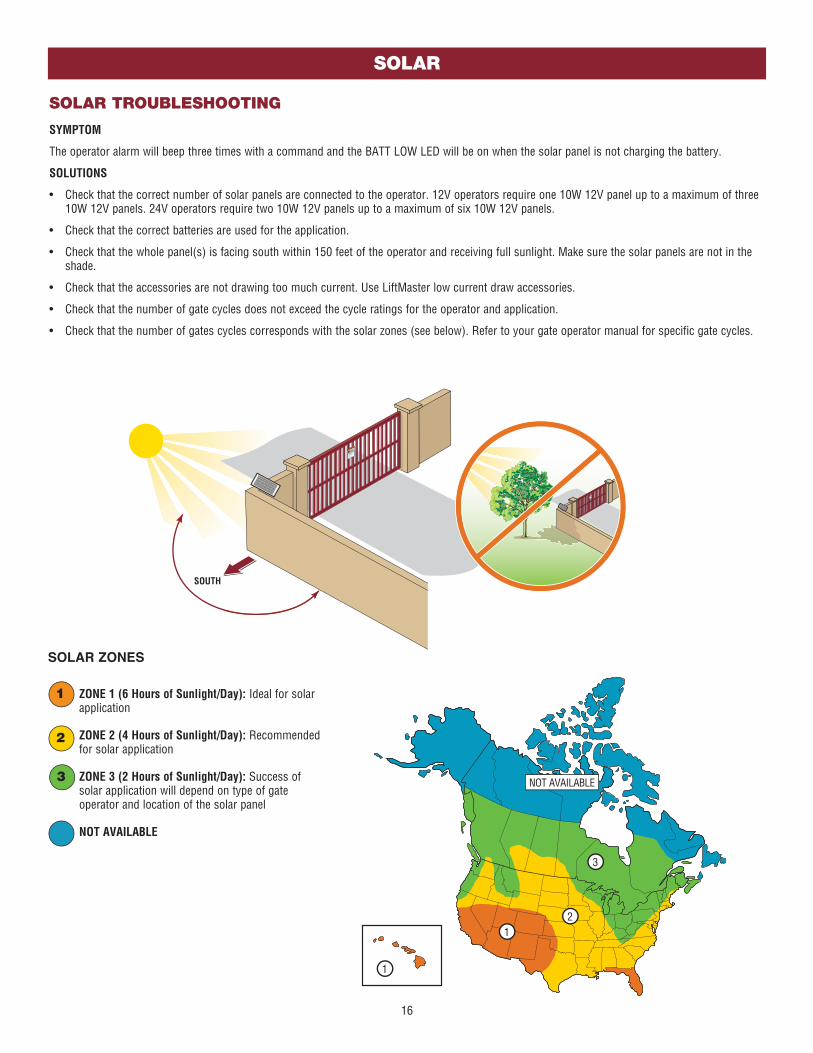
ZONE 1 (6 Hours of Sunlight/Day): Ideal for solar application
ZONE 2 (4 Hours of Sunlight/Day): Recommended for solar application
ZONE 3 (2 Hours of Sunlight/Day): Success of solar application will depend on type of gate operator and location of the solar panel
NOT AVAILABLE
3
2
1
NOT AVAILABLE
1
12
3
SOLAR TROUBLESHOOTING
SYMPTOM
The operator alarm will beep three times with a command and the BATT LOW LED will be on when the solar panel is not charging the battery.
SOLUTIONS
• Check that the correct number of solar panels are connected to the operator. 12V operators require one 10W 12V panel up to a maximum of three 10W 12V panels. 24V operators require two 10W 12V panels up to a maximum of six 10W 12V panels.
• Check that the correct batteries are used for the application.
• Check that the whole panel(s) is facing south within 150 feet of the operator and receiving full sunlight. Make sure the solar panels are not in the shade.
• Check that the accessories are not drawing too much current. Use LiftMaster low current draw accessories.
• Check that the number of gate cycles does not exceed the cycle ratings for the operator and application.
• Check that the number of gates cycles corresponds with the solar zones (see below). Refer to your gate operator manual for specific gate cycles.
SOUTH

17
SOLAR
24V APPLICATIONS
Disconnect all power (AC, solar, battery) to the operator before servicing. NOTE: 10W 12V solar panels are illustrated in the image below.
Diode
40W
60W33AH Batteries (in series)
To “BATT DC POWER” input on control board
33AH BATTERIES
7AH BATTERIES
A
B C
D
A J15 Plug
B Red wire for 33AH battery connections
C Black wire for 33AH battery connections
D White jumper wire for 33AH battery connections
ITEMS NEEDED FOR 24V APPLICATIONS
Diode
7AH Batteries (in series)
A
Existing Jumper
(battery connections) (solar panel connections)
The remaining wires in the kit are not needed for 24V applications.
To “BATT DC POWER” input on control board
20W
40W
60W
20W

18
12V APPLICATIONS
Disconnect all power (AC, solar, battery) to the operator before servicing. NOTE: 10W 12V solar panels are illustrated in the image below.
Diode
20W7AH Battery
To “BATT DC POWER” input on control board
ONE 7AH BATTERY
TWO 7AH BATTERIES
AA J15 Plug
B Red wire for 33AH battery connections
C Black wire for 33AH battery connections
E Red jumper wire for two 7AH battery connections
ITEMS NEEDED FOR 12V APPLICATIONS
Diode
7AH Batteries (in parallel)
To “BATT DC POWER” input on control board
A
Fuse
(battery connections) (solar panel connections)
The remaining wires in the kit are not needed for 12V applications.
F Black jumper wire for two 7AH battery connections
(fuse)
E
F
B C
A
Diode
To “BATT DC POWER” input on control board
ONE 33AH BATTERY
33AH Battery
Solar panels are wired in parallel.
30W
10W
20W
Solar panels are wired in parallel.
30W
10W
20W
Solar panels are wired in parallel.
30W
10W
SOLAR
19
POWER
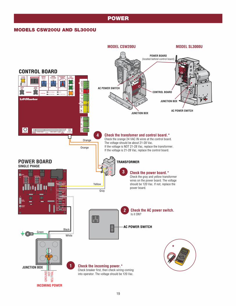
MODELS CSW200U AND SL3000U
CO
MM
LIN
K
BA
ANTENNA CURRENT SENSOR
MOTOR DRIVE RPM & LIMITS ALARM EXP.BOARD
24 VAC IN CLA
SS
2 S
UP
PLY
24 V
AC
500 m
A M
AX
ID RESET
GN
D
BIPARTDELAY
2
4
6
8
HANDING
OPENLEFT
OPENRIGHT
MOTOR
ID
J14
MOTOR RED MOTOR BLUE
J11
J7 SWITCH
TRANSFORMERJ5
J3
COMM
120VAC
MOTOR
WHITEJ2
J1INPUT
NEUTRAL
OUTLETJ12
J6 BLACK
WHITE
INPUT
HOTJ4
J10
MOTOR
CONTROL
CURRENT
SENSOR
J8
J16
SWITCH
J17
J20
J13
J19
J21
J18
COM
120240
COM
120240
24 V c.a.24 V c.a.
CONTROL BOARD
TRANSFORMER
Orange
Orange
POWER BOARDSINGLE PHASE
Black
JUNCTION BOX
INCOMING POWER
White
AC POWER SWITCH
Green
Yellow
Gray
HOT
NEUT
RAL
GROU
ND
*
1 Check the incoming power.*Check breaker first, then check wiring cominginto operator. The voltage should be 120 Vac.
2 Check the AC power switch.Is it ON?
Check the power board.*Check the gray and yellow transformerwires on the power board. The voltage should be 120 Vac. If not, replace the power board.
3
Check the transfomer and control board.*Check the orange 24 VAC IN wires at the control board. The voltage should be about 21-28 Vac.If the voltage is NOT 21-28 Vac, replace the transformer. If the voltage is 21-28 Vac, replace the control board.
4
CONTROL BOARD
MODEL CSW200U
POWER BOARD
(located behind control board)
MODEL SL3000U
JUNCTION BOX
AC POWER SWITCH
AC POWER SWITCH
JUNCTION BOX

20
POWER
MODELS SL585U AND SL595U (SINGLE PHASE)
CO
MM
LIN
K
BA
ANTENNA CURRENT SENSOR
MOTOR DRIVE RPM & LIMITS ALARM EXP.BOARD
24 VAC IN CLA
SS
2 S
UP
PLY
24 V
AC
500 m
A M
AX
ID RESET
GN
D
BIPARTDELAY
2
4
6
8OPENLEFT
OPENRIGHT
HANDING
CONTROL BOARD
TRANSFORMER
120VOUTLET
PWR IN HOT(BLACK)
SWITCH(YELLOW)
J1
5J1
4
J1
3
(BLACK)
(WHITE)
J11 J12
PWR IN
J1NEUTRAL(WHITE)
SWITCH(ORANGE) J
7
COMM(WHITE)
120V(BLACK)
208V(RED)
240V(ORANGE) J
9J5
J3
J4
J2
J1
6J6
J10
CURRENTSENSOR
120V
120V
240V
240V
J8
J1
7
COM
120
240
480
208
BlackWhite
OrangeRed
TRANSFORMER
Blac
k
Black
POWER BOARDSINGLE PHASE
JUNCTION BOX
White
White
AC POWER SWITCH
GreenHOTNEUTRAL
GROUND
Yellow
Blue
To configure the motor for 208V, swap the orange and red wires and plug motor into the 240V position.
24 VAC
3.15A FUSE
INCOMING POWER
1 Check the incoming power.*Check breaker first, then check wiring coming into operator. The voltage should be 120, 208, or 240 Vac dependingon the application.
2 Check the AC power switch.Is it ON?
*
CONTROL BOARD
MODEL SL595U
POWER BOARD
MODEL SL585U
AC POWER
SWITCH
JUNCTION
BOX
POWER BOARDCONTROL BOARD
JUNCTION BOX
Check the power board.*Check the following transformer wires on the power board: 120V Applications: Check the white and black wires, voltage should be 120 Vac208V Applications: Check the white and red wires, voltage should be 208 Vac240V Applications: Check the white and orange wires, voltage should be 240 VacIf the voltage is not correct, replace the power board.
3
Check the transfomer and
control board.*Check the blue and yellow 24 VAC IN wires at the control board. The voltage should be about 21-28 Vac.If the voltage is NOT 21-28 Vac, replace the transformer. If the voltage is 21-28 Vac, replace the fuse. If the fuse is good, replace the control board.
4
Fuse

21
POWER
MODELS SL585U AND SL595U (THREE PHASE)
TRANSFORMERJ14
J11
J12
LINE IN
J1L1
J2L2
J3L3
J7
CO
MM
WH
ITE
(BLACK)
(WHITE)
(PURPLE)
208V
RED
240/5
75V
OR
AN
GE
480V
PU
RP
LE
J9
J5J4
J6
MOTORCURRENT
480V
BRAKE
240V/208V575V
J8
J10
12V
12V
24
V
J13
CO
MM
LIN
K
BA
ANTENNA CURRENT SENSOR
MOTOR DRIVE RPM & LIMITS ALARM EXP.BOARD
24 VAC IN CL
AS
S 2
SU
PP
LY
24
VA
C5
00
mA
MA
X
ID RESET
GN
D
BIPARTDELAY
2
4
6
8OPENLEFT
OPENRIGHT
HANDING
COM
120
240
460
208
CONTROL BOARD
Purple
White
OrangeRed
TRANSFORMER
L1 B
lack
Blac
k
POWER BOARDTHREE PHASE
JUNCTION BOXL2 W
hite
Whi
te
Green
Yellow
Blue
To configure the motor for 208V, swap the orange and red wires and plug motor into the 208V / 240V position.
24 VAC
3.15A FUSE
L3 P
urpl
e
Purp
le
NCOMING POWER
SWITCH
Check the power board.*Check the following transformer wires on the power board: 208V Applications: Check the white and red wires, voltage should be 208 Vac240V Applications: Check the white and orange wires, voltage should be 240 Vac480V Applications: Check the white and purple wires, voltage should be 480 VacIf the voltage is not correct, replace the power board.
3
1 Check the incoming power.*Check breaker first, then check wiring coming into operator. The voltage should be 208, 240, or 480 Vac depending on the application.
*
Check the transfomer and
control board.*Check the blue and yellow 24 VAC IN wires at the control board. The voltage should be about 21-28 Vac.If the voltage is NOT 21-28 Vac, replace the transformer. If the voltage IS 21-28 Vac, replace the fuse. If the fuse is good, replace the control board.
4
CONTROL BOARD
MODEL SL595U
POWER BOARD
AC POWER SWITCH
2 Check the AC power switch.Is it ON?
MODEL SL585U
AC POWER
SWITCH
JUNCTION
BOX
POWER BOARDCONTROL BOARD
JUNCTION BOX
Fuse
22
POWER
Diode
20A
Battery12V 7AH
Battery12V 7AH
Solar Panels10W minimum - 30W maximum, wired in parallel
10W 12V10W 12V
20A
10W 12V
J15 Plug
Black
Red
Black
Red
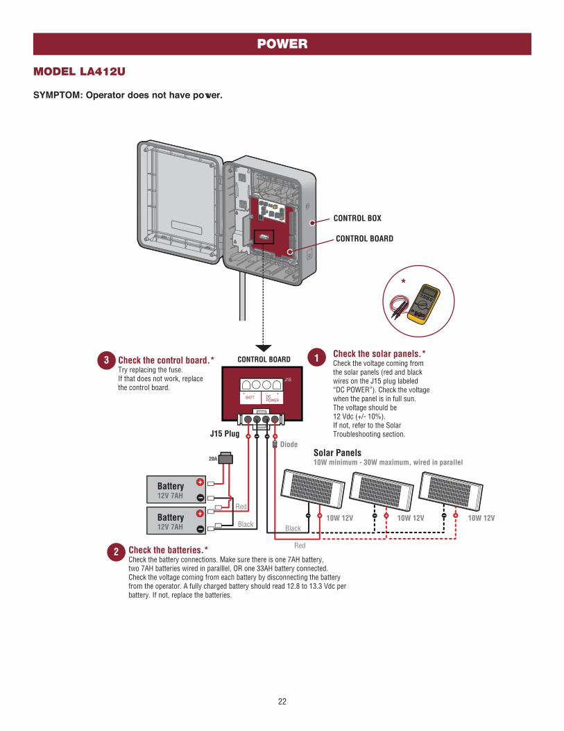
CONTROL BOX
1 Check the solar panels.*Check the voltage coming from the solar panels (red and blackwires on the J15 plug labeled “DC POWER”). Check the voltagewhen the panel is in full sun.The voltage should be 12 Vdc (+/- 10%). If not, refer to the Solar Troubleshooting section.
2 Check the batteries.*Check the battery connections. Make sure there is one 7AH battery, two 7AH batteries wired in paralllel, OR one 33AH battery connected. Check the voltage coming from each battery by disconnecting the battery from the operator. A fully charged battery should read 12.8 to 13.3 Vdc per battery. If not, replace the batteries.
3 Check the control board.*Try replacing the fuse. If that does not work, replace the control board.
*
CONTROL BOARD
CONTROL BOARD
MODEL LA412U
SYMPTOM: Operator does not have power.

23
POWER
MODEL LA400U
SYMPTOM: Operator does not have power.
Battery12V 7AH
Battery12V 7AH
CONTROL BOARD
J15 Plug
Black
Red
CONTROL BOX
3 Check the batteries.*Check the battery connections. Make sure two 7AH batteries OR two 33AH batteries are connected in series. Check the voltage coming from each battery by disconnecting the battery from the operator. A fully charged battery should read 12.8 to 13.3 Vdc per battery. If not, replace the batteries.
4 Check the control board.*Try replacing the fuse. If that does not work, replace the control board.
*
CONTROL BOARD
(Back of Outlet Housing)
Outlet
Outlet
HOT
NEUT
RAL
GROU
NDBl
ack
Gree
nW
hite
Incoming Power
Incoming Power
1 Check the
incoming power.*Check breaker first, thencheck wiring cominginto operator. The reading should be 120 Vac.
OUTLET HOUSING
DIAGNOSTICS
2 Check the transformer.*Check the voltage coming from the transformer (red and black wires at the CHARGER terminals).The reading should be 34 Vdc (+/- 10%).If not, replace the transformer.
BlackRed

24
POWER
120120 240240
Oran
geYe
llow
Power Wiring Sockets
(120 Vac factory
default)
EMI BOARD
Transformer
Battery
12V 7AH
Battery
12V 7AH
CONTROL BOARD
Incoming Power
HOT
NEUT
RAL
GROU
ND
Blac
k
Gree
nW
hite
BridgeRectifier
J15 Plug
Black
Red
Black
Red
PurpleGray
BrownBlue
Black
Red
1 Check the
incoming power.*Check breaker first, thencheck wiring cominginto operator. The voltage should be 120 Vac or 240 Vac dependingon the application.
Incoming Power
CONTROL BOX
2
Check the AC
power switch.Is it ON?
3 Check the power
wiring connector.Is it plugged into the correct socket?
4
Check the transformer.*Check the transformer voltage going into the bridge rectifier (orange and yellow wires). The reading should be 24 Vac (+/- 10%). If not, replace the transformer.
*
5
Check the bridge
rectifier.*Check the voltage coming out of the bridge rectifer (red and black wires).The reading should be 24 Vdc (+/- 10%). If not, replace the bridge rectifier.
7 Check the control
board.Try replacing the fuse on the control board. If that does not work, replace the control board.
6 Check the batteries.*Check the battery connections. Make sure two 7AH batteries OR two 33AH batteries are connected in series. Check the voltage coming from each battery by disconnecting the battery from the operator. A fully charged battery should read 12.8 to 13.3 Vdc per battery. If not, replace the batteries.
CONTROL BOARD
TRANSFORMER
BRIDGE RECTIFIER
AC POWER SWITCH
MODEL LA500U
SYMPTOM: Operator does not have power.

25
MODELS CSL24U AND CSW24U
SYMPTOM: Operator does not have power.
POWER
+-
- -
BRIDGE
RECTIFIER
Orange
Black
Red BlackRed
Orange
Power Wiring Connector
Power Wiring Sockets
(120 Vac factory
default)
EMI
BOARD
(Back of Outlet Housing)
Input Power Connection
TRANSFORMER
Battery
12V 7AH
Battery
12V 7AH
Gray
Blue
Brown
Purple
Black
White
HOT
NEUT
RAL
GROU
ND
Black
White
Green
OUTLET HOUSING
CONTROL BOARD
J15 Plug
1
2
3 4
5
6
Check the
incoming power.*Check breaker first, thencheck wiring cominginto operator. The voltage should be 120 Vac or 240 Vac dependingon the application.
Check the AC power switch.Is it ON?
Check the power
wiring connector.Is it plugged into the correct socket?
Check the transformer.*Check the transformer voltage going into the bridge rectifier (orange wires). The reading should be 24 Vac (+/- 15%). If not, replace the transformer.
Check the bridge
rectifier.*Check the voltage coming out of the bridge rectifer (red and black wires).The reading should be 35 Vdc (+/- 15%). If not, replace the bridge rectifier.
7 Check the control
board.Try replacing the fuse on the control board. If that does not work, replace the control board.
Check the batteries.*Check the battery connections. Make sure two 7AH batteries OR two 33AH batteries are connected in series. Check the voltage coming from each battery by disconnecting the battery from the operator. A fully charged battery should read 12.8 to 13.3 Vdc per battery. If not, replace the batteries.
*
OUTLET HOUSING
DIAGNOSTICS
Fuse
CONTROL BOARD
TRANSFORMER and BRIDGE RECTIFIER
located on chassis, behind the electrical box.
BATTERIES
MODEL CSL24UMODEL CSW24U
BATTERIESOUTLET HOUSING
CONTROL BOARD
TRANSFORMER and BRIDGE RECTIFIER
located on chassis, behind the electrical box.
120120 240240

26
Black
Red
Battery12V 7AH
CONTROL BOARD
OUTLET HOUSING
(Back of Outlet Housing)
Incoming Power
HOT
NEUT
RAL
GROU
ND
Outlet
Blac
kGr
een
Whi
te
Outlet
J15 Plug
1 Check the incoming power.*Check breaker first, then check voltage cominginto operator. The voltage should be 120 Vac.
3 Check the control board.*Try replacing the fuse on the control board. If that does not work, replace the control board.
DIAGNOSTICS
Fuse
2 Check the batteries.*Check the battery connections. Make sure one 7AH battery OR one 33AH battery is connected. Check the voltage coming from each battery by disconnecting the battery from the operator. A fully charged battery should read 12.8 to 13.3 Vdc per battery. If not, replace the batteries.
*
POWER
MODELS RSL12U AND RSW12U
SYMPTOM: Operator does not have power.

27
MYQ®
FREQUENTLY ASKED QUESTIONS
What do I need to activate the gate operator using MyQ®?
a. Router
b. Internet connection
c. Internet Gateway
d. Internet Gateway serial number (located on the bottom of the Internet Gateway)
e. MyQ-Enabled Gate Operator
What is an Internet Gateway?
The Internet Gateway (828LM), is a 900 MHz Internet Protocol device for monitoring and controlling MyQ devices (e.g. gate operator or light control).
Does an Internet Protocol Address or Dynamic Host Configuration Protocol need to be established for the Internet Gateway?
Yes, the Internet Gateway (828LM) requires a Dynamic Host Configuration Protocol (DCHP).
What is the required speed of the Ethernet port for the Internet Gateway?
The Internet Gateway is a 10 Mb/s device.
How does the Internet Gateway connect to an existing residential or commercial network?
The Internet Gateway needs to be connected to a Local Area Network port on a network router or network switch, establishing connection to the Internet. When the Internet Gateway connects to the Internet, a secure session is established with the MyQ server.
What Transmission Control Protocol (TCP) and/or User Datagram Protocol (UDP) ports need to be opened in our firewall?
The Internet Gateway uses User Datagram Protocol (UDP) port 80 for inbound and outbound data messages and uses Transmission Control Protocol (TCP) port 2165 for firmware updates. If a firewall or network security appliance is on the network (e.g. SonicWALL®), the User Datagram Protocol (UDP) Timeout setting needs to be set to 180 seconds or greater. See the Incompatible Router and Switch section for more information.
Can the Internet Gateway be pinged to verify connection to a network?
The Internet Gateway does not support a ping response.
Can a static IP address be established on the Internet Gateway?
A static IP address cannot be established on this device. The Internet Gateway requires the router/Dynamic Host Configuration Protocol (DCHP) to provide a Local Area Network (LAN) Internet Protocol (IP) address.
How can the Internet Gateway be tested from the Internet?
To test the Internet Gateway from the Internet, do either of the following:
a. Add the Internet Gateway to a MyQ account. If the Internet Gateway is already on a MyQ account, add a MyQ-Enabled device (e.g. gate operator or light control) to the MyQ account.
b. If a MyQ-Enabled device is already on the MyQ account, provide a command (open/close, on/off) using the MyQ app.

28
MyQ®
FREQUENTLY ASKED QUESTIONS
Can the Internet Gateway be connected from a remote location using the Wide Area Network (WAN) to our corporate offices and access the Internet from the corporate location?
If the Internet Gateway is successfully connected to the MyQ® server (green LED on MyQ Gateway is illuminated and solid), the MyQ app can monitor and control a MyQ device from any location. All MyQ-Enabled devices must be on the MyQ account and be within transmitting capability of the Internet Gateway.
Are communications to/from the Internet Gateway encrypted?
The Internet Gateway uses AES-128 encryption for all communications through the Internet. The Internet Gateway uses proprietary data encryption over 900 MHz to/from MyQ devices.
How can the MAC address of the Internet Gateway be obtained?
To obtain the MAC address, connect the Internet Gateway to a network router and use a computer to login into the router and locate the MAC address within the connected devices list. A MAC address for an Internet Gateway should be in the following format: 64:52:99: XX: XX: XX.
How to put a MyQ Gate Operator into programming/learn mode:
Press the learn button twice on the primary operator (the operator will beep as it enters learn mode). The Internet Gateway will pair to the gate operator if it is within range, and the gate operator will beep again if programming is successful.
How to use the RESET button to put a MyQ Gate Operator into programming / learn mode when the gate is closed:
1. Ensure the gate is closed.
2. Give the gate operator an OPEN command.
3. Within 30 seconds, when the gate is at the open limit, press and release the RESET button 3 times (on the primary gate) to put the primary operator into high band learn mode (the gate operator will beep as it enters learn mode).
4. The Internet Gateway will pair to the gate operator if it is within range and the gate operator will beep again if programming is successful.
5. The status as shown by the Internet Gateway app will be either “open” or “closed”. The gate operator can then be controlled through the Internet Gateway app.

29
MyQ®
TROUBLESHOOTING MyQ®
If issues are experienced when adding an Internet Gateway, a LiftMaster Gate Operator or light control to a MyQ® account, please review the troubleshooting topics below.
CONNECTION ISSUES
PROBLEM
If the green LED on the Internet Gateway is not illuminated or blinking, the Internet Gateway is not connected to the Internet.
SOLUTION
There are a few different reasons an Internet Gateway will not successfully connect to the Internet:
• An incompatible router
• A router configuration setting (e.g. MAC address filtering)
• A network security appliance (firewall)
PROBLEM
Green LED on the Internet Gateway is off. The router or network switch is not providing an IP address to the Internet Gateway.
SOLUTION
• Verify power to the Internet Gateway. Disconnect and reconnect power to the Internet Gateway. The blue and green LEDs should blink on and off a few times when the Internet Gateway is initially powered.
• Check the Ethernet cable connections between the Internet Gateway, router, or network switch.
• Confirm the router or network switch is providing a connection to the Internet.
• Check if the router or switch is incompatible with the Internet Gateway. Go to LiftMaster.com/MyQ-PAS and look for the Incompatible Router and Switch section.
• Connect the Internet Gateway to a different LAN port on the router or network switch.
Determine if a router setting is preventing the Internet Gateway from obtaining an IP address (e.g. MAC address filtering, firewall settings).
• Review the router’s settings and manual.
• Router must be set to DHCP to provide an IP address to the Internet Gateway.
• The Internet Gateway requires UDP port 80 to have a UDP timeout of 180 seconds or greater.
Reset the router. Disconnect power to the router for 30 seconds. Reconnect power to the router. Wait up to 5 minutes after the router is active to determine if the green LED on the Internet Gateway is illuminated solid or blinking.
PROBLEM
Green LED on the Internet Gateway is blinking. If the green LED on the Internet Gateway is blinking, the Internet Gateway has obtained an IP address from the router, but the Internet Gateway is not connecting to the MyQ® server.
SOLUTION
Determine if a router setting (e.g. firewall setting) is preventing the Internet Gateway from communicating with the Internet.
• Review the router’s settings and manual.
• The Internet Gateway requires UDP port 80 to have a UDP timeout of 180 seconds or greater.
Determine if a network security appliance (firewall, e.g. SonicWALL®, ZyWall) is installed.
• Determine if the network security settings are preventing connection of the Internet Gateway to the Internet.
• The Internet Gateway requires UDP port 80 to have a UDP timeout of 180 seconds or greater. SonicWALL’s UDP timeout must be adjusted to be 180 seconds or longer for both inbound and outbound data traffic.
See SonicWALL Fire Wall section for more information.

30
MyQ®
MyQ® ACCOUNT ISSUES
Unable to add more than one MyQ device to a MyQ account:
• Prior to adding MyQ devices, an account must be established. An account can be created by visiting MyLiftMaster.com or by downloading the MyQ app from a smartphone or tablet app store.
• Up to sixteen MyQ devices may be added to one Internet Gateway (828LM). If more than sixteen MyQ devices are required, additional Internet Gateways can be installed and added to the same MyQ account. For optimal performance of MyQ, the maximum number of devices added per account should not exceed 32.
• MyQ provides the ability to monitor and control MyQ-Enabled Gate Operators at more than one location from the same account. To monitor and control MyQ-Enabled Gate Operators at more than one location, additional Internet Gateways will be required at each location.
• An illuminated blue LED will be solid on an Internet Gateway when one or more MyQ devices (gate operator or light control) are paired to an Internet Gateway. The blue LED will not illuminate if no MyQ devices are paired to the Internet Gateway
NOTE: A MyQ device can only be associated (added) to one MyQ account.
If a MyQ device fails to add to a MyQ account, please review the troubleshooting steps below:
If a pop-up error message appears on the MyQ app when attempting to add a device, verify the MyQ device is not already associated with another MyQ account. If the “add device” process times out after three minutes, the MyQ device may not be in the programming/learn mode or may be out of range of the Internet Gateway.
Sample error message that may be encountered: No response, gate operator is not responding. Please try again later.
PROBLEM
Unable to add a MyQ-Enabled Gate Operator to a MyQ account.
SOLUTION
• Confirm the Internet Gateway is powered and the green LED illuminated and solid.
• Confirm the Internet Gateway is added to the MyQ account.
• Confirm the MyQ-Enabled Gate Operator is in the programming/learn mode.
• Confirm the signal from the Internet Gateway can reach the MyQ-Enabled Gate Operator. Depending upon obstructions, the average range from the Internet Gateway is between 300 to 600 feet. Are there too many walls between the Internet Gateway and the gate operator?
To test a MyQ-Enabled Gate Operator, program a remote control to the operator and stand near the Internet Gateway. Test if a remote control can operate the MyQ-Enabled Gate Operator. If necessary, relocate the Internet Gateway closer to the MyQ-Enabled Gate Operator using a longer CAT5 cable or higher quality Ethernet cable (up to 100 feet).
• Confirm the antenna is installed on the gate operator. The antenna is included inside a poly bag on the gate operator cover along with the installation manual, user guide and quick start guide.
• MyQ-Enabled devices communicate using a 900 MHz radio signal. Electronic devices in the same area of the Internet Gateway or MyQ devices may create a range issue. Some troubleshooting options include powering down or relocating other 900 MHz products (900 MHz cordless phone, etc.) in the area of the MyQ device causing the interference.

31
PROBLEM
The MyQ-Enabled Gate Operator will not respond to the app.
SOLUTION
• Confirm the green LED on the Internet Gateway is illuminated and solid. If the green LED is not illuminated or blinking, see Connection Issues section.
• For a MyQ-Enabled Gate Operator, confirm that the operator is powered up and fully operational. Control the MyQ-Enabled Gate Operator from a remote control.
• Confirm the MyQ-Enabled Gate Operator has been added to the MyQ account (a gate operator image should be present on the Places screen of the app).
• Confirm the signal from the Internet Gateway can reach the MyQ-Enabled Gate Operator. Depending upon obstructions, the average range from the Internet Gateway is between 300 to 600 feet. Are there too many walls between the Internet Gateway and the gate operator?
To test a MyQ-Enabled Gate Operator, program a remote control to the operator and stand near the Internet Gateway. Test if a remote control can operate the MyQ-Enabled Gate Operator. If necessary, relocate the Internet Gateway closer to the MyQ-Enabled Gate Operator using a longer CAT5 cable or higher quality Ethernet cable (up to 100 feet).
• MyQ devices communicate using a 900 MHz radio signal. Electronic devices in the same area of the Internet Gateway or MyQ-Enabled Gate Operator may create a range issue. Some troubleshooting options include powering down or relocating other 900 MHz products (900 MHz cordless phone, etc.) in the area of the MyQ-Enabled Gate Operator causing the interference.
MyQ®
MyQ® ACCOUNT ISSUES

32
MyQ®
MyQ® ERROR CODES
Below are potential error codes that may be encountered when working with the Internet Gateway, MyQ® app, MyQ website, or your PC or smartphone.
GENERAL ERROR CODES
ERROR CODE MESSAGE ISSUE AND RESOLUTION
209 Unable to remove device. • Server was not able to confirm the deletion or removal of a device.
• If you continue to experience a problem, contact the LiftMaster Technical Service Center at 800.528.2806.
223 Gateway is offline. • Check the power outlet and identify if the blue and green LED’s on Internet Gateway are illuminated.
• If the Internet Gateway appears to have no Internet connection, verify a computer in the facility attached to the network has an Internet connection by loading a web page.
• Log out of account. Restart the Internet Gateway by powering off and then back on. The Internet Gateway will need to be unplugged to power off. Log back into the account.
• If you continue to experience a problem, contact the LiftMaster Technical Service Center at 800.528.2806.
224 Gateway is in learn mode. • The app or website may not have connected to the MyQ server, please try again.
• Log out of the account. Restart the Internet Gateway by powering off and back on. The Internet Gateway will need to be unplugged to power off.
• Log into the account and attempt to reprogram devices.
• If you continue to experience a problem, contact the LiftMaster Technical Service Center at 800.528.2806.
301 The Gateway or hub serial number was invalid.
• Identify the serial number located on the bottom of the Internet Gateway.
• Verify the serial number. Ensure a 0 is a number.
• Try again to register the device with the correct serial number.
• If you continue to experience a problem, contact the LiftMaster Technical Service Center at 800.528.2806.
303 Gateway serial number is not recognized after several attempts.
• Identify the serial number on the bottom of the Internet Gateway.
• Verify the serial number. Ensure a 0 is a number.
• Try again to register the device with the correct serial number.
• Delete the account and create a new account.
• If you continue to experience a problem, contact the LiftMaster Technical Service Center at 800.528.2806.
304 Please make sure the device* is connected and the green LED is solid ON.
• Check the power outlet and identify if the green LED on the Internet Gateway device is illuminated.
• Log out of the account. If the Internet Gateway appears to not have an Internet connection, verify a computer in the facility attached to the network has an Internet connection by loading a web page. Restart the Internet Gateway by powering off and back on. The Internet Gateway will need to be unplugged to power off.
• If you continue to experience a problem, contact the LiftMaster Technical Service Center at 800.528.2806.
* A MyQ-Enabled Gate Operator is considered a device.

33
MyQ® ERROR CODES
Below are potential error codes that may be encountered when working with the Internet Gateway, MyQ® app, MyQ website, or your PC or smartphone.
GENERAL ERROR CODES
ERROR CODE MESSAGE ISSUE AND RESOLUTION
305 The device* is currently in Learn Mode.
• The application or website may not have connected with the MyQ® server, please try again.
• Log out of the account. Restart the Internet Gateway by powering off and back on. The Internet Gateway will need to be unplugged to power off. Log back into the account and attempt to reprogram the device.
• If you continue to experience a problem, contact the LiftMaster Technical Service Center at 800.528.2806.
308 A device* is not responding. • Ensure the MyQ device* is powered and within range of the Internet Gateway.
• A MyQ device* is not responding. Verify the device is plugged into an outlet with power.
• Operate device manually.
• If the device responds, remove the device from the account. Add the device back to the account. If the device does not respond, the device may need to be replaced or serviced.
• Contact a local dealer or LiftMaster Technical Service Center at 800.528.2806.
309 The Gateway is offline. • The Internet Gateway has no power. Check the power outlet and identify if the green and blue LED’s on the Internet Gateway device are illuminated.
• If the Internet Gateway appears to not have an Internet connection, verify a computer in the facility attached to the network has an Internet connection by loading a web page. Log out of the account. Restart the Internet Gateway by powering off and back on. The Internet Gateway will need to be unplugged to power off. Log back into the account.
310 Device is on another user’s account and unable to register.
• The Internet Gateway or device is already registered to another account.
• T he device must be removed from the account before it can be added to a new account. If you have access to the other account, log into the account and remove the device. If you do not have access to the other account, you will not be able to add it to a new account.
* A MyQ-Enabled Gate Operator is considered a device.
MyQ®

34
INCOMPATIBLE ROUTER AND SWITCH
MyQ®
INCOMPATIBLE ROUTER
When installing an Internet Gateway, issues have been identified with the following routers/modems:
MANUFACTURER MODEL
Belkin® F5D8236-4 (Only works on LAN ports 1 & 3)
D-Link® DIR-665
Hauwei® Router/Modem Echolife HG520C
Linksys®/Cisco® WRT610N version 1
Netgear® CGD24G Cable Modem
SMC Networks® SMC8014WN
TRENDnet® 5-Port-10/100mbps Switch TE100-S5
Ubee® DDW3610
Verizon® Actiontec M1424-WRREV (Rev E) Modem Router
Westell® Modems A90-7500 DSL Modem
The above routers use non-standard internal port wiring incompatible with the Internet Gateway. A hub or switch may resolve this situation, but is not a verified fix.
INCOMPATIBLE NETWORK SWITCH
When installing an Internet Gateway, an identified issue has been associated with the following network switch:
MANUFACTURER MODEL
TRENDnet 5-Port-10/100Mbps TE100-S5
SONICWALL® FIRE WALL
PROBLEM
The performance issues listed below are caused by SonicWALL’s factory default UDP connection timer being set to 30 seconds, which closes the Internet Gateway connection to the server after the Internet Gateway enters its sleep state and reduces its communication to the server to once every 60 seconds. When this occurs, the Internet Gateway will take up to 2 minutes to recognize connection to the server is lost before having to re-establish connection. This process will continue to repeat.
When a MyQ® device is behind a SonicWALL Network Appliance, the following MyQ app performance issues may occur:
• Difficulty controlling a MyQ device through the MyQ app.
• Manual operation by a MyQ device may not change status on the MyQ app (gate operator is closed by pressing the remote control, but app shows gate open).
• Upon power cycling of an Internet Gateway, the app will work for a brief period of time and then enter a non-working state.
SOLUTION
The SonicWALL UDP Connection timer should be changed to 120 seconds or greater. LiftMaster® recommends a minimum value of 180 seconds. The timer must be changed in multiple locations.
• The default UDP timer should be changed, which will change the UDP connection timer for any new rule made to the SonicWALL.
• Any current LAN -> WAN rules must have the UDP connection timeout updated manually. Set “Default UDP Connection Timeout (seconds):” to “360” and set “UDP Connection Inactivity Timeout (seconds):” to “360”.

PAS002 © 2015, LiftMaster – All Rights Reserved
845 Larch Avenue
Elmhurst, Illinois 60126-1196
LiftMaster.com