pas 2016: 2010 - next generation access for new build ... · pas 2016:2010 next generation access...
TRANSCRIPT
PAS 20162010
Next generation access for new build homes ndash Guide
PAS 20162010
copy BSI December 2010
Publishing and copyright information The BSI copyright notice displayed in this document indicates when the document was last issued
copy BSI 2010
ISBN 978 0 580 67917 9
ICS 3304001 9104030
No copying without BSI permission except as permitted by copyright law
This Publicly Availble Specification comes into effect on 6th December 2010
Date Text affected
Amendments issued since publication
PAS 20162010
Contents
Foreword ii
iiiIntroduction
1 Scope 1
2 Normative references 1
23 Terms and definitions
4 Domestic dwelling digital infrastructure 4
5 Boundary between internal and external infrastructure 5
6 External infrastructure 8
7 Internal digital infrastructure 9
8 Installation testing 14
9 Documentation and handover 15
Bibliography 16
List of figures
Figure 1 ndash Domestic digital installations 6
Figure 2 ndash Generic zones of liability 7
Figure 3 ndash Pin grouping and pair assignments for BS EN 60603-7 series connecting hardware (front view of connector) 12
Figure 4 ndash Cable ducting diagram 13
copy BSI December 2010 i
ii
PAS 20162010
copy BSI December 2010
Foreword
This Publicly Available Specification (PAS 20162010) was sponsored by the
Department for Business Innovation and Skills (BIS) and its development was
facilitated by the British Standards Institution (BSI)
Acknowledgement is given to Mike Perry of BRE (the Building Research Establishment) as the Technical Author for this Publicly Available Specification
BSI also wishes to acknowledge the following organizations that were involved in the development of this Publicly Available Specification
bull BT
bull Derby City Council
bull Digital Communications Knowledge Transfer Network (DC-KTN)
bull HCA
bull Independent Fibre Networks Ltd amp NICC
bull Land Securities
bull Miniflex
bull OpenHub
bull PRP
bull Willmott Dixon
Wider comments from other interested parties were invited by BSI The expert contributions made by the organizations and individuals consulted in the development of this Publicly Available Specification are gratefully acknowledged
This PAS has been prepared and published by BSI which retains its ownership and copyright BSI reserves the right to withdraw or amend this PAS on receipt of authoritative advice that it is appropriate to do so This PAS will be reviewed at intervals not exceeding two years and any amendments arising from the review will be published as an amended PAS and publicized in Update Standards
Use of this document
As a guide this Publicly Available Specification takes the form of guidance and recommendations It should not be quoted as if it were a specification and particular care should be taken to ensure that claims of compliance are not misleading
Any user claiming compliance with this Publicly Available Specification is expected to be able to justify any course of action that deviates from its recommendations
It has been assumed in the preparation of this Publicly Available Specification that the execution of its provisions will be entrusted to appropriately qualified and experienced people for whose use it has been produced
Presentational conventions
The provisions in this standard are presented in roman (ie upright) type Its recommendations are expressed in sentences in which the principal auxiliary verb is ldquoshouldrdquo It does not contain requirements
Commentary explanation and general informative material is presented in smaller italic type and does not constitute a normative element
The word ldquoshouldrdquo is used to express recommendations of this standard The word ldquomayrdquo is used in the text to express permissibility eg as an alternative to the primary recommendation of the clause The word ldquocanrdquo is used to express possibility eg a consequence of an action or an event
Notes and commentaries are provided throughout the text of this standard Notes give references and additional information that are important but do not form part of the recommendations
Contractual and legal considerations
This publication does not purport to include all the necessary provisions of a contract Users are responsible for its correct application
Compliance with a British Standard cannot confer immunity from legal obligations
PAS 20162010
Introduction
The UK is embarking on the process of installing a national digital infrastructure to support the delivery of broadband digital services particularly to the home setting via high-speed internet access referred to in this Public Available Specification (PAS) as ldquobroadbandrdquo The Coalition Agreement provides the Governmentrsquos views aspirations for superfast broadband and objectives on how this can be achieved The Government aims to ensure the UK has the best superfast broadband network in Europe by 2015 This is tackled in more detail in the Governmentrsquos National Broadband Strategy Britainrsquos Superfast Broadband Future published in December 2010
The initial residential use of the internet was driven by PC-based services such as web browsing and email Subsequent use has increasingly included a wider range of applications including video and others which will involve machine to machine communication for applications such as meter reading security telecare etc This development has involved an increase in the number of devices to be connected in individual homes and this trend will continue
A digital infrastructure has two parts to it connection to the house and distribution within the house This parallels with the delivery of electricity Service delivery depends on ldquoend-to-end connectivityrdquo ie a connection from the broadband supplier right through to the device situated within the home and therefore needs both parts of the distribution system
A network in the home benefits the delivery of the digital services as well as providing convenience to the home owner This also has the potential of providing the developer with an attractive marketing opportunity
An easier challenge is to install digital infrastructure into all new build domestic dwellings While cabled media is the preferred digital infrastructure particularly for demanding high bandwidth video distribution wireless connectivity is also likely to play a significant role Wireless provides convenience and flexibility for the connection of mobile devices in particular eg laptops
copy BSI December 2010 iii
PAS 20162010
1 Scope
This Publicly Available Specification (PAS) provides guidance and a practical framework to identify the recommendations for digital communications infrastructures to and within new build domestic dwellings supporting effective installation in new build homes
The PAS addresses
1) single dwelling units ie houses which are individual dwellings not sharing common parts (other than party walls) with other houses and
2) multi-dwelling units ie housing where multiple separate housing units for residential (ie non-commercial) inhabitants are contained within one building
The PAS is not intended for
a) other multiple occupancy buildings such as hostels ie where residents having their own rooms share facilities
NOTE For example common kitchens
b) community-wide wireless infrastructures and
NOTE While these are important in the provision of digital infrastructure they are not within the scope of this PAS
c)the external provision of digital infrastructure to locations where wired infrastructure is not practical
NOTE This is for further study
The PAS is intended for house developers and builders and all those concerned with supplying installing commissioning or operating digital infrastructure and related services in new build homes
NOTE The intention is not to mandate a specific technology or supplier but to identify a minimum standard of connectivity which can be fulfilled in a number of ways
2 Normative references
The following reference documents are required for the application of this document For dated references only the edition cited applies For undated references the latest edition of the referenced document (including any amendments) applies
ANSI-TIA-568-C0 Generic telecommunications cabling for customer premises
ANSI-TIA-568-C2 Balanced twisted-pair telecommunications cabling and components standards
BS 6701 Telecommunications equipment and telecommunications cabling ndash Specification for installation operation and maintenance
BS 7671 Requirements for electrical installations ndash IEE Wiring Regulations ndash Seventeenth edition
BS EN 50173-1 Information technology ndash Generic cabling systems ndash Part 1 General requirements
BS EN 50173-4 Information Technology ndash Generic cabling ndash Part 4 Homes
BS EN 50174-1 Information technology ndash Cabling installation ndash Part 1 Installation specification and quality assurance
BS EN 50174-2 Information technology ndash Cabling installation ndash Part 2 Installation planning and practices inside buildings
BS EN 50346 Information technology ndash Testing of installed cabling
BS EN 60603-7 Connectors for electronic equipment ndash Part 7 Detail specification for 8-way unshielded free and fixed connectors for data transmissions with frequencies up to 100 MHz
copy BSI December 2010 1
PAS 20162010
3 Terms and definitions
For the purpose of this PAS the following terms and definitions apply
31 assistive living (telecare and telehealth)
digital services used to support independent lifestyle (telecare) or the remote delivery of healthcare services (telehealth)
NOTE These services are often but not exclusively supplied to the elderly or anyone with chronic long term conditions eg diabetes II dementia chronic obstructive pulmonary disease (COPD) irrespective of age
32 active infrastructure
active equipment for receiving transmitting or distributing digital data and information
33 balanced cablesconnectors
metallic cables of twisted pair construction and associated connectors of a specified category of performance
34 bandwidth
measure of the capacity of a transmission system to deliver information
NOTE In general the greater the bandwidth of the transmission system the greater the data transmission rate it is able to deliver
35 broadband
high-speed ldquoalways onrdquo internet access
36 cabled aggregation aperture
collation point for all the internal network cables where they enter the customer premises equipment (CPE) space
37 cabled media
balanced and optical fibre cables and connectors used for the transmission of digital data and services
38 category of balanced cables connectors
hierarchical system of performance classification for balanced cablesconnectors
NOTE Higher category components have higher performance and bandwidth
39 customer premises equipment (CPE)
digital home equipment normally active used for the reception transmission and distribution of digital data and services
NOTE For example WiFi router
310 data transmission rate
measure of the information delivered over a network typically expressed in bits per second
NOTE High-definition television (HDTV) requires a data transmission rate of c 10 Mbs
311 digital communications infrastructure
infrastructure required for digital communications allowing reception of data and information services delivered externally and for the transmission of digital data and information within a domestic dwelling
copy BSI December 2010 2
PAS 20162010
312 fibre optic
transmission technology that allows for the transmission of digital data by light pulses using optical fibre cable and fibre optic connecting hardware
NOTE Optical fibre can be either glass or plastic
313 home distributor (HD) panel
equipment for interconnecting data ports by means of short connecting cables or cords
NOTE For example a switch (an active device) to be connected with the required output socket normally using equipment cords
314 internet service provider
commercial supplier of digital content and services
315 local area network (LAN)
main distribution point that connects to a main street cabinet and then to a jointing chamber which provides the final link to the external wall of the dwelling
NOTE The internal network within the dwelling together with equipment such as routers (outside the scope of this PAS) also form part of the LAN
316 network termination point (NTP)
final connection point and demarcation between the external and internal networks and installed by the supplier
NOTE Beyond this point the developer builder or occupier has liability for the digital infrastructure
317 optical fibre cables and fibre optic connectors
all-silica (glass) or plastic fibre optic cables and associated connectors
318 passive infrastructure
non-active parts of the digital infrastructure
NOTE This includes cables and outlet sockets and contain no active elements
319 power line communications (PLC)
use of electrical power cables for the distribution of digital data and content
320 residential gateway
device combining in one unit a number of active pieces of equipment for the distribution of digital data and content and an access network interface
321 service provider
telecommunications operator or other entity responsible for the connection of a household to the global internet
322 star topology
network where digital service outlets are connected to a common central point
NOTE For example in home networks the residential gateway or switch by dedicated connections
323 supplier
provider of digital infrastructure services or both
324 router
primary active equipment interfacing external and internal networks of a dwelling and connecting digital devices in the home to form an internal network
NOTE 1 There may be more than one switch needed in an internal network
NOTE 2 It is often integrated into the residential gateway
325 wireless deadspot
location in a building or the built environment where the reception of wireless signals is not possible because of signal blocking or other interference
326 wireless links
use of radio transmissions to carry digital data
copy BSI December 2010 3
PAS 20162010
4 Domestic dwelling digital infrastructure
41 General
The objective of a domestic dwelling digital infrastructure is to provide
a) broadband connectivity to the internet and
b) distribution network for the reception and transmission of digital signals and services throughout the dwelling These services may or may not involve an access connection ie there can be services which are solely confined to the dwelling
NOTE For example home entertainment energy services telecare and telehealth services ndash referred to as assistive living services
NOTE 1 The objective of the Coalition Government is to ensure the UK has the best superfast broadband network in Europe by 2015 through market deployment or through strategic intervention in areas the market will not reach In doing so the Coalition also aims to achieve in virtually every home access to a minimum of 2 Mbs broadband connectivity In new build homes 2 Mbs is a lower bound Up to 24 Mbs is already the standard in respect of asymmetric digital subscriber line (ADSL) very high speed digital subscriber line (VDSL) from the street cabinet will increase this Hybrid Fibre Coax Networks already deliver up to 50 Mbs New build infrastructure can be designed to support rates far greater than these data rates eg 100 Mbs
In densely populated urban areas this is unlikely to be a problem while in remote rural areas without a cabled connection achieving this bandwidth can be challenging
Next generation distribution systems in new build homes should be able to support 2 Mbs transmissions but also have a much higher capability so they can handle the likely increases to Mbs This high data rate can only be reliably supported on a cabled infrastructure
Within the dwelling balanced cabling is the most practical medium with optical fibre cabling being considered as an optional addition for future installations
For new build dwellings a cabled medium should be used as the transmission medium of preference
Most users are likely to use wireless distribution in addition to the fixed infrastructure with the
latter primarily being used for the most demanding applications eg video distribution especially high definition and video on demand
Wireless provides convenience and offers the possibility of connecting to the internet from any place in the dwelling provided there are no wireless deadspots However cabled medium is required to connect wireless routers to the Internet Wireless connectivity is assumed in this PAS to provide a supplementary method of connectivity to broadband services used in conjunction with cabled media
In the context of new build domestic dwellings providing free access to cable routes then power line communications are unlikely to be a major consideration Although power line communications are an alternative option in the context of existing properties and refurbishment this is beyond the scope of this PAS
All dwellings are likely to have digital terrestrial or satellite TV connectivity or both These requirements should be included in the specification of the home network providing digital interconnectivity between such TVs and associated for example programmable video recorders (PVRs) Digital video disc (DVD) and Blu-ray players other digital devices within the home and the ldquoresidential gatewayrdquo
copy BSI December 2010 4
PAS 20162010
5 Boundary between internal and external infrastructure
51 General
This PAS describes the external and internal digital infrastructures separately The division between the two is defined by the demarcation point a legally defined point in the provision of telecommunications services at which responsibility for the infrastructure passes from the service provider to the householder The demarcation point is defined differently in different countries In the UK there will be active or passive (ie un-powered or powered) NTP which belongs to the telecommunications provider and which isolates the incoming connection from the customerrsquos equipment (see Figure 1)
In UK new build homes the following should be considered for the external infrastructure including
a) there is an individual connection (metallic or optical fibre) to an individual dwelling from the service providerrsquos equipment external to the curtilage of the dwelling In this case the demarcation point
will be at or within the boundary of the curtilage of the dwelling
b) there is a connection to the individual dwelling but this is provided from the service providerrsquos equipment installed in a location owned and or managed by the organization responsible for common parts
NOTE For example a building or estate management company
c)the service provider delivers service to a demarcation point external to individual dwellings and final distribution is managed by an organization responsible for common parts An example of this would be an estate or municipality that wishes to provide its own local digital infrastructure In such cases a secondary demarcation point will exist for each attached dwelling
copy BSI December 2010 5
PAS 20162010
Figure 1 ndash Domestic digital installations
Digital cupboard
Property boundary
NTP
Cust
omer
hub
Patc
h le
ads
Patc
h pa
nel
Cat
5e c
able
s Outlet
Outlet
Demarcation point
Outlet
copy BSI December 2010 6
PAS 20162010
52 Liability
This PAS is focused on the internal digital infrastructure contained within the bounding walls of the dwelling and gives guidance on the external connection from the jointing chamber This is the most immediate external connection point linking the dwelling infrastructure with the external networks most often it is located in the street beyond the curtilege of the property
The reason for the distinction between external and internal digital infrastructure is that up to the NTP liability rests with the infrastructure installer or ISP
Figure 2 ndash Generic zones of liability
Beyond the external termination point liability for the internal digital infrastructure lies with the builder developer or customer unless installed by the service provider
However ultimate liability for the internal network remains with the householder even if he contracts that to another entity
The generic zones of liability for a typical single dwelling unit are shown in Figure 2
Builder developer liability
Builder developer or customer responsibility
ISP telecommunications company or infrastructure contractorrsquos liability
Jointing chamber
ISP telecommunications ISP liability company or infrastructure contractorrsquos liability
Main district server room
Estate distribution point
copy BSI December 2010 7
PAS 20162010
6 External infrastructure
61 Local Area Network (LAN) connections
The connection of a domestic dwelling to an external digital network is the end of point of the external Local Area Network (LAN) with the internal network also being an LAN or home network The demarcation point between external and internal networks is the NTP
In the local area the main distribution point for the external LAN should be an exchange or a server room This connects to a main street cabinet (primary connection point) and then to a jointing chamber which provides the final link to the external wall of the dwelling
62 Connection to the external wall of the property
For all telecommunication services a NTP should be installed internally or externally to allow entry of the data infrastructure into the home
NOTE See CLG guidance on data ducting for new homes which describes best practice in relation to external entry into new homes [1]
The NTP is the demarcation point between the providerrsquos external network and the developer customer-provided cabling All internal cabling beyond the NTP should be the responsibility of the builder customer and after handover the customer
copy BSI December 2010 8
PAS 20162010
7 Internal digital infrastructure
71 Overview
Internal digital infrastructure should consist of both cabled and wireless elements
The design of generic information technology cabling in homes is specified in BS EN 50173-4 The specification of those installations and their quality assurance is specified in BS EN 50174-1 Particular requirements for installation planning and practices in homes are specified in BS EN 50174-2
BS EN 50173-4 requires that cabling be implemented in a star configuration from a home distributor (HD) located in a ldquoprimary distribution spacerdquo which is separately specified in BS EN 50174-2 Exceptionally for large buildings additional star points [secondary home distributors (SHDs)] may be used to serve areas of the building not easily served by the primary star point Where possible the demarcation point should be co-located with the HD
The installation of unscreened balanced cabling components of Category 5 should be installed in accordance with BS EN 50173-1 (equivalent to Category 5e of ANSI-TIA-568-C2) which also meets the minimum implementation of BS EN 50173-4
A star topology is a network where the data outlets are connected to a common central point in home networks the residential gateway or switch by dedicated connections The main benefits of a star network is reliability ndash if one of the ldquopoint-to-pointrdquo segments is broken only the devices on that link will be affected and not affect other devices on other arms of the star
72 External to internal connection ndash Houses and multi-dwelling units
The ducting should be laid from the footway jointing chamber (with the socket end presented to the joint box) and terminate with a pre-formed 90deg bend at the outside of the house wall The duct runs should be kept to a minimum depth of cover of 350 mm beneath the proposed finish level (450 mm under a soft surface)
20 mm electrical conduit should be supplied and installed through the cavity wall at a point vertically above the end of the service duct A back box or single-gang flush steel box should be installed in
preparation for the installer to fit and commission the connection to the active digital equipment eg switch or other type of main socket
All ducts should be provided with a draw rope after installation unless local agreement is made to substitute the draw rope for lead-in cable 1 m at the house and 3 m at the tail in the chamber should be left
The service duct should be cut level two bricks below the damp proof course it should be sealed at both ends using a duct plug to prevent ingress of debris
copy BSI December 2010 9
PAS 20162010
73 Primary distribution space
731 Accommodation
In each dwelling the cabled CPE the presentation of the home cabling and associated equipment should be accommodated in a primary distribution space as specified in BS EN 50174-2 which is secure (lockable)
This space should be located in for example an under-stairs cupboard or a similar location
The primary distribution space should be provided with two-twin gang switched 13A sockets installed in accordance with BS 7671
When designing the house installation sufficient dimensions for the cable aggregation aperture should be designed-in ndash to the point where all cables and ducts enter the equipment space An aperture diameter of 50 mm is adequate in most cases
On exiting the primary distribution space
a) BS EN 50174-2 requires that the pathway between the dwelling entrance and the primary distribution space shall have a cross-section equivalent to a minimum diameter of 38 mm (consistent with Size 40 conduits of BS EN 61386 series)
b) BS EN 50174-2 requires that the pathway between the primary distribution space and the outlets shall have a cross-section equivalent to a minimum diameter of 16 mm (consistent with Size 20 conduits of BS EN 61386 series)
The location should allow for ease of connection and maintenance access between the incoming service duct and the termination at the CPE The location of the primary distribution space should be agreed early in the design of the dwellings
copy BSI December 2010 10
PAS 20162010
The space should be located to avoid extremes of temperature and humidity The standard ambient temperature range is 0 degC - 44 degC Humidity should be kept within a range to avoid the risk of condensation
The equipment may be mounted in a 19 in rack or other suitable mounting system including wall mounted sockets Where used the rack system can be floor mounted or wall mounted There should be sufficient capacity to allow for expansion of the number of wall sockets throughout the house to provide two twin outlets per room excluding bathrooms and toilets
NOTE This may not comply with the recommendations of BS EN 50173-4 for large rooms but may over-provide for smaller rooms and is judged to provide a good guide
All cabinets frames or racks accommodated within the primary distribution space should be earthed in accordance with BS 6701 Any power supply cabling provided to these cabinets frames or racks should be carried out in accordance with BS 7671
732 Customer premises equipment (CPE)
The initial CPE should provide sufficient outlet ports to service
a) two telephone points and
b) four independent data service outlets on the switch or residential gateway
733 Presentation of home cabling
The outlets terminating the home cabling should be mounted on a panel(s) to allow interconnection to CPE and where appropriate to other outlets on the panel(s)
74 Premises distribution cabling
741 General provision
In the case of all internal cabling it is essential that the developer designs the cable routes and socket placements to achieve the maximum capability for the delivery of multiple services to all main rooms
NOTE This way all the benefits offered by the network can be realized
Pathways should be provided throughout the home to provide each room two twin outlets per room excluding bathrooms and toilets The required pathways should be carried out in accordance with 731
The developer should install cabling for data services using cables and connectors in accordance with 742
For ldquoconnectedrdquo (digitally wired) homes there should be as a minimum data outlets in the lounge master bedroom and study locations and also to each location where a co-axial socket is deployed for TV services
In this way multiple services such as high speed Internet or broadband TV content can be delivered simultaneously A star wire configuration should connect each room in the dwelling using the ceiling rose as the primary connection point in each room This provides an ease of access for dropping communications cables to any location in the room
Data outlet sockets should be mounted in the range 700 ndash 900 mm [2] This is for ease of access for people in wheelchairs and on the ground floor to help reduce damage in the event of floods
742 Cables and connectors
Balanced cables should be unscreened Category 5 in accordance with BS EN 50173-1 (which are equivalent to the unshielded Category 5e cables of ANSI-TIA-568-C2)
The maximum length of the cables should be 90 m in accordance with the reference implementations of BS EN 50173-4 or ANSI-TIA-568-C2 respectively
The presentation of the home cabling at the HD and the wall sockets distributed through the home should be in accordance with BS EN 60603-7 (commonly but inaccurately referred to as RJ45) As specified for telecommunications outlets in BS EN 50173-4 these connectors should be of the same type (ie unscreened or screened) and category as the balanced cable The termination of the cable at those outlets should be as shown in Figure 3
NOTE Unscreened category 5 connectors are specified in BS EN 60603-7-2 Higher category of unscreened and screened connectors are specified in other parts of the BS EN 60603-7 standards series
copy BSI December 2010 11
PAS 20162010
Figure 3 ndash Pin grouping and pair assignments for BS EN 60603-7 series connecting hardware (front view of connector)
1 2 3 4 5 6 7 8
743 Data cable runs
Balanced cables should be kept at a minimum separation of 50 mm from mains power cables
NOTE BS 7671 delegates the requirements for separationsegregation between power supply and telecommunications cabling to BS 6701 (for safety protection) and to BS EN 50174-2 (for suppression of electrical interference) This PAS may comply with these requirements provided that the power supply cable (or bundle of cables) is not carrying in excess of 100 amps
The user of this PAS is recommended to comply with the wider requirements of BS 6701 and BS EN 50174-2 where this separation cannot be maintained
744 Wireless connectivity
Wireless can also be deployed enabling mobility around the home An end-user may choose to collocate an ISPrsquos residential gateway either at the cabled CPE location (leading to further ISP fan out over the star wired data sockets) or at the end of any of the 4 times star wired data sockets
NOTE 1 For example the ISPrsquos residential gateway may be deployed in a home office
NOTE 2 Wireless networking may form part of the ldquofinal legrdquo of the home network where it provides a reasonable alternative to physical cabling to data points
The location of wireless access points should be tested to ensure the effectiveness of their transmission and reception and that they are not located in a wireless deadspot
745 Blank data sockets and cable ducting
7451 Blank data sockets
The minimum number of recommended cabled data sockets per house is four At least one double back box and blanking plate should be located in each room in the house excluding bathrooms toilets and storage cupboards
Each blank double data socket should be mounted close to double socket power outlets in accordance with BS 7671
7452 Cable ducting
Cable ducting provides an open infrastructure to accept current or future cabling solutions throughout the dwelling This allows quick and easy expansion or upgrade during the life of the building with no impact or damage to the physical structure or decorative finishes
Ducting should be laid from the central distribution point the CPE space to every power socket in the premise at the same time as providing the power cabling to each socket
NOTE 1 BS EN 50174-2 requires that the pathway between the primary distribution space and the outlets have a cross-section equivalent to a minimum diameter of 16 mm (consistent with Size 20 conduits of BS EN 61386 series)
Duct is most often supplied on standard reels with a pre-installed pull-cord and secure end plugs These plugs protect against ingress of dirt and other contamination To lock the pull-cord in position to prevent accidental pull-out these plugs should be retained and refitted to the installed duct and remaining unused duct
The installer should carry a supply of end plugs to cap off duct that has been installed in the home until the duct is populated with cables The installer should satisfy himself that the duct is clean and suitable for use or scrap the remaining product
NOTE 2 The viability of stored duct without plugs is suspect
The duct can be routed across walls or along timber studs and joists and fixed using standard cabling clips and ties using conventional installation practices
copy BSI December 2010 12
PAS 20162010
The duct should not be routed under or between moveable services or other objects that could cause crushing
The duct may be buried in plaster or floor screeds
The minimum recommended bend radius should typically be 150 mm but in all cases the manufacturersrsquo specification should be adhered to
A double sweep should be used when negotiating internal or external corners as shown in Figure 4
Figure 4 ndash Cable ducting diagram
Capped power cable feed to double gang power sockets
Power socket with plastic optical fibre (POF) media converter and Ethernet RJ45 data socket
Duct containing plastic optical fibre (POF) from ethernet hub
All ducts radiate from central distribution hub adjacent to ethernet hub
Source Miniflex
After populating the duct with the required data cables foam plugs should be fitted into the annular gap at both ends to prevent ingress of dust or insects
746 Fire resistance
NOTE Attention is drawn to all elements of the digital infrastructure installation with the appropriate fire regulations for domestic dwellings
Twin RJ45 ethernet data
Double gang power socket with empty feed for future data upgrade
Twin ducts containing category 5 copper cables from ethernet hub
150 mm radius
copy BSI December 2010 13
PAS 20162010
8 Installation testing
The completed infrastructure installation should be tested as fully operational The results of the tests should be documented and included with the documentation passed to the homeowner or occupier
NOTE The responsibility for testing the installation lies with the installing contractor
The balanced cabling from the home distributor to the telecommunication outlets should be tested in accordance with BS EN 50346 to confirm that the transmission performance meets the permanent link requirements of Class D of BS EN 50173-1 (or Category 5e of ANSI-TIA-568-C2)
All-silica optical fibre cabling from the home distributor to the telecommunication outlets should be tested in accordance with BS EN 50346 to confirm that the transmission performance meets the permanent link requirements of BS EN 50173-1 (or ANSI-TIA-568-C0)
Plastic optical fibre cabling from the home distributor to the telecommunication outlets should be tested in accordance with BS EN 50346 to confirm that the transmission performance meets the permanent link requirements of BS EN 50173-1
copy BSI December 2010 14
PAS 20162010
9 Documentation and handover
All outlets at the home distributor and throughout the dwelling should be clearly labelled in accordance with BS EN 50174-1
The labelling of outlet sockets face-plates will be unacceptable if located on the exposed face of the socket The label should be fixed within the faceplate back box The labelling should be firmly located to ensure it is not displaced when the faceplate is removed
The location dimensions andor capacity of pathways into which information technology cabling has been
installed should be recorded together with details of any mitigation measures applied to provide the required environment in accordance with BS EN 50174-1 These recordings should include the position of the CPE equipment within the primary distribution space
This documentation should be passed to the occupier of the property when they move into the dwelling
The documentation should include digital installation instructions and should be passed to subsequent occupiers
copy BSI December 2010 15
PAS 20162010
Bibliography
Standards publications
BS EN 61386ndash 1 Conduit systems for cable management ndash Part 1 General requirements
BS EN 61386ndash 21 Conduit systems for cable management ndash Particular requirements ndash Part 21 Rigid conduit systems
BS EN 61386ndash 22 Conduit systems for cable management ndash Particular requirements ndash Part 22 Pliable conduit systems
BS EN 61386ndash 23 Conduit systems for cable management ndash Particular requirements ndash Part 23 Flexible conduit systems
BS EN 61386ndash 24 Conduit systems for cable management ndash Particular requirements ndash Part 24 Conduit systems buried underground
Other publications
[1] Data Ducting Infrastructure for New Homes Guidance Note CLG March 2008
[2] Stephen Thorpe and Habinteg Housing Association Wheelchair housing design guide (2nd edition) BRE Press February 2006
Further reading
BS EN 50174-3 Information technology ndash Cabling installation ndash Part 3 Installation planning and practices outside buildings
BT Openreach ndash Buildersrsquo Guide to telecommunications infrastructure and installation May 2007
NICC Report April 2010 (full reference to be confirmed)
National Joint Utilities Group ndash Guidelines On The Positioning And Colour Coding Of Utilitiesrsquo Apparatus NJUG April 2003
copy BSI December 2010 16
PAS 20162010
BSI ndash British Standards Institution
BSI is the independent national body responsible for preparing British Standards
It presents the UK view on standards in Europe and at the international level
It is incorporated by Royal Charter
Revisions British Standards are updated by amendment or revision Users of British Standards should make sure that they possess the latest amendments or editions
It is the constant aim of BSI to improve the quality of our products and services We would be grateful if anyone finding an inaccuracy or ambiguity while using this Publicly Available Specification would inform the Information Centre
Tel +44 (0)20 8996 7111 Fax +44 (0)20 8996 7048 Email infobsigroupcom
BSI offers members an individual updating service called PLUS which ensures that subscribers automatically receive the latest editions of standards
Buying standards Orders for all BSI international and foreign standards publications should be addressed to Customer Services
Tel +44 (0)20 8996 9001 Fax +44 (0)20 8996 7001 Email ordersbsigroupcom
Standards are also available from the BSI website at wwwbsigroupcomshop
Information on standards BSI provides a wide range of information on national European and international standards through its Library Various BSI electronic information services are also available which give details on all its products and services Contact the Information Centre
Tel +44 (0)20 8996 7111 Fax +44 (0)20 8996 7048 Email infobsigroupcom
Subscribing members of BSI are kept up to date with standards developments and receive substantial discounts on the purchase price of standards For details of these and other benefits contact Membership Administration
Tel +44 (0)20 8996 7002 Fax +44 (0)20 8996 7047 Email membershipbsigroupcom
Information regarding online access to British Standards via British Standards Online can be found at wwwbsigroupcombsol
Further information about BSI is available on the BSI website at wwwbsigroupcom
Copyright Copyright subsists in all BSI publications BSI also holds the copyright in the UK of the publications of the international standardization bodies Except as permitted under the Copyright Designs and Patents Act 1988 no extract may be reproduced stored in a retrieval system or transmitted in any form or by any means ndash electronic photocopying recording or otherwise ndash without prior written permission from BSI
This does not preclude the free use in the course of implementing the standard of necessary details such as symbols and size type or grade designations If these details are to be used for any other purpose than implementation then the prior written permission of BSI must be obtained
Details and advice can be obtained from the Licensing Department
Tel +44 (0)20 8996 7070 Fax +44 (0)20 8996 7512 Email copyrightbsigroupcom
copy BSI December 2010 17
British Standards Institution 389 Chiswick High Road London W4 4AL United Kingdom
wwwbsigroupcom
ISBN 978shy0shy580shy67917shy9
9 780580 679179

PAS 20162010
copy BSI December 2010
Publishing and copyright information The BSI copyright notice displayed in this document indicates when the document was last issued
copy BSI 2010
ISBN 978 0 580 67917 9
ICS 3304001 9104030
No copying without BSI permission except as permitted by copyright law
This Publicly Availble Specification comes into effect on 6th December 2010
Date Text affected
Amendments issued since publication
PAS 20162010
Contents
Foreword ii
iiiIntroduction
1 Scope 1
2 Normative references 1
23 Terms and definitions
4 Domestic dwelling digital infrastructure 4
5 Boundary between internal and external infrastructure 5
6 External infrastructure 8
7 Internal digital infrastructure 9
8 Installation testing 14
9 Documentation and handover 15
Bibliography 16
List of figures
Figure 1 ndash Domestic digital installations 6
Figure 2 ndash Generic zones of liability 7
Figure 3 ndash Pin grouping and pair assignments for BS EN 60603-7 series connecting hardware (front view of connector) 12
Figure 4 ndash Cable ducting diagram 13
copy BSI December 2010 i
ii
PAS 20162010
copy BSI December 2010
Foreword
This Publicly Available Specification (PAS 20162010) was sponsored by the
Department for Business Innovation and Skills (BIS) and its development was
facilitated by the British Standards Institution (BSI)
Acknowledgement is given to Mike Perry of BRE (the Building Research Establishment) as the Technical Author for this Publicly Available Specification
BSI also wishes to acknowledge the following organizations that were involved in the development of this Publicly Available Specification
bull BT
bull Derby City Council
bull Digital Communications Knowledge Transfer Network (DC-KTN)
bull HCA
bull Independent Fibre Networks Ltd amp NICC
bull Land Securities
bull Miniflex
bull OpenHub
bull PRP
bull Willmott Dixon
Wider comments from other interested parties were invited by BSI The expert contributions made by the organizations and individuals consulted in the development of this Publicly Available Specification are gratefully acknowledged
This PAS has been prepared and published by BSI which retains its ownership and copyright BSI reserves the right to withdraw or amend this PAS on receipt of authoritative advice that it is appropriate to do so This PAS will be reviewed at intervals not exceeding two years and any amendments arising from the review will be published as an amended PAS and publicized in Update Standards
Use of this document
As a guide this Publicly Available Specification takes the form of guidance and recommendations It should not be quoted as if it were a specification and particular care should be taken to ensure that claims of compliance are not misleading
Any user claiming compliance with this Publicly Available Specification is expected to be able to justify any course of action that deviates from its recommendations
It has been assumed in the preparation of this Publicly Available Specification that the execution of its provisions will be entrusted to appropriately qualified and experienced people for whose use it has been produced
Presentational conventions
The provisions in this standard are presented in roman (ie upright) type Its recommendations are expressed in sentences in which the principal auxiliary verb is ldquoshouldrdquo It does not contain requirements
Commentary explanation and general informative material is presented in smaller italic type and does not constitute a normative element
The word ldquoshouldrdquo is used to express recommendations of this standard The word ldquomayrdquo is used in the text to express permissibility eg as an alternative to the primary recommendation of the clause The word ldquocanrdquo is used to express possibility eg a consequence of an action or an event
Notes and commentaries are provided throughout the text of this standard Notes give references and additional information that are important but do not form part of the recommendations
Contractual and legal considerations
This publication does not purport to include all the necessary provisions of a contract Users are responsible for its correct application
Compliance with a British Standard cannot confer immunity from legal obligations
PAS 20162010
Introduction
The UK is embarking on the process of installing a national digital infrastructure to support the delivery of broadband digital services particularly to the home setting via high-speed internet access referred to in this Public Available Specification (PAS) as ldquobroadbandrdquo The Coalition Agreement provides the Governmentrsquos views aspirations for superfast broadband and objectives on how this can be achieved The Government aims to ensure the UK has the best superfast broadband network in Europe by 2015 This is tackled in more detail in the Governmentrsquos National Broadband Strategy Britainrsquos Superfast Broadband Future published in December 2010
The initial residential use of the internet was driven by PC-based services such as web browsing and email Subsequent use has increasingly included a wider range of applications including video and others which will involve machine to machine communication for applications such as meter reading security telecare etc This development has involved an increase in the number of devices to be connected in individual homes and this trend will continue
A digital infrastructure has two parts to it connection to the house and distribution within the house This parallels with the delivery of electricity Service delivery depends on ldquoend-to-end connectivityrdquo ie a connection from the broadband supplier right through to the device situated within the home and therefore needs both parts of the distribution system
A network in the home benefits the delivery of the digital services as well as providing convenience to the home owner This also has the potential of providing the developer with an attractive marketing opportunity
An easier challenge is to install digital infrastructure into all new build domestic dwellings While cabled media is the preferred digital infrastructure particularly for demanding high bandwidth video distribution wireless connectivity is also likely to play a significant role Wireless provides convenience and flexibility for the connection of mobile devices in particular eg laptops
copy BSI December 2010 iii
PAS 20162010
1 Scope
This Publicly Available Specification (PAS) provides guidance and a practical framework to identify the recommendations for digital communications infrastructures to and within new build domestic dwellings supporting effective installation in new build homes
The PAS addresses
1) single dwelling units ie houses which are individual dwellings not sharing common parts (other than party walls) with other houses and
2) multi-dwelling units ie housing where multiple separate housing units for residential (ie non-commercial) inhabitants are contained within one building
The PAS is not intended for
a) other multiple occupancy buildings such as hostels ie where residents having their own rooms share facilities
NOTE For example common kitchens
b) community-wide wireless infrastructures and
NOTE While these are important in the provision of digital infrastructure they are not within the scope of this PAS
c)the external provision of digital infrastructure to locations where wired infrastructure is not practical
NOTE This is for further study
The PAS is intended for house developers and builders and all those concerned with supplying installing commissioning or operating digital infrastructure and related services in new build homes
NOTE The intention is not to mandate a specific technology or supplier but to identify a minimum standard of connectivity which can be fulfilled in a number of ways
2 Normative references
The following reference documents are required for the application of this document For dated references only the edition cited applies For undated references the latest edition of the referenced document (including any amendments) applies
ANSI-TIA-568-C0 Generic telecommunications cabling for customer premises
ANSI-TIA-568-C2 Balanced twisted-pair telecommunications cabling and components standards
BS 6701 Telecommunications equipment and telecommunications cabling ndash Specification for installation operation and maintenance
BS 7671 Requirements for electrical installations ndash IEE Wiring Regulations ndash Seventeenth edition
BS EN 50173-1 Information technology ndash Generic cabling systems ndash Part 1 General requirements
BS EN 50173-4 Information Technology ndash Generic cabling ndash Part 4 Homes
BS EN 50174-1 Information technology ndash Cabling installation ndash Part 1 Installation specification and quality assurance
BS EN 50174-2 Information technology ndash Cabling installation ndash Part 2 Installation planning and practices inside buildings
BS EN 50346 Information technology ndash Testing of installed cabling
BS EN 60603-7 Connectors for electronic equipment ndash Part 7 Detail specification for 8-way unshielded free and fixed connectors for data transmissions with frequencies up to 100 MHz
copy BSI December 2010 1
PAS 20162010
3 Terms and definitions
For the purpose of this PAS the following terms and definitions apply
31 assistive living (telecare and telehealth)
digital services used to support independent lifestyle (telecare) or the remote delivery of healthcare services (telehealth)
NOTE These services are often but not exclusively supplied to the elderly or anyone with chronic long term conditions eg diabetes II dementia chronic obstructive pulmonary disease (COPD) irrespective of age
32 active infrastructure
active equipment for receiving transmitting or distributing digital data and information
33 balanced cablesconnectors
metallic cables of twisted pair construction and associated connectors of a specified category of performance
34 bandwidth
measure of the capacity of a transmission system to deliver information
NOTE In general the greater the bandwidth of the transmission system the greater the data transmission rate it is able to deliver
35 broadband
high-speed ldquoalways onrdquo internet access
36 cabled aggregation aperture
collation point for all the internal network cables where they enter the customer premises equipment (CPE) space
37 cabled media
balanced and optical fibre cables and connectors used for the transmission of digital data and services
38 category of balanced cables connectors
hierarchical system of performance classification for balanced cablesconnectors
NOTE Higher category components have higher performance and bandwidth
39 customer premises equipment (CPE)
digital home equipment normally active used for the reception transmission and distribution of digital data and services
NOTE For example WiFi router
310 data transmission rate
measure of the information delivered over a network typically expressed in bits per second
NOTE High-definition television (HDTV) requires a data transmission rate of c 10 Mbs
311 digital communications infrastructure
infrastructure required for digital communications allowing reception of data and information services delivered externally and for the transmission of digital data and information within a domestic dwelling
copy BSI December 2010 2
PAS 20162010
312 fibre optic
transmission technology that allows for the transmission of digital data by light pulses using optical fibre cable and fibre optic connecting hardware
NOTE Optical fibre can be either glass or plastic
313 home distributor (HD) panel
equipment for interconnecting data ports by means of short connecting cables or cords
NOTE For example a switch (an active device) to be connected with the required output socket normally using equipment cords
314 internet service provider
commercial supplier of digital content and services
315 local area network (LAN)
main distribution point that connects to a main street cabinet and then to a jointing chamber which provides the final link to the external wall of the dwelling
NOTE The internal network within the dwelling together with equipment such as routers (outside the scope of this PAS) also form part of the LAN
316 network termination point (NTP)
final connection point and demarcation between the external and internal networks and installed by the supplier
NOTE Beyond this point the developer builder or occupier has liability for the digital infrastructure
317 optical fibre cables and fibre optic connectors
all-silica (glass) or plastic fibre optic cables and associated connectors
318 passive infrastructure
non-active parts of the digital infrastructure
NOTE This includes cables and outlet sockets and contain no active elements
319 power line communications (PLC)
use of electrical power cables for the distribution of digital data and content
320 residential gateway
device combining in one unit a number of active pieces of equipment for the distribution of digital data and content and an access network interface
321 service provider
telecommunications operator or other entity responsible for the connection of a household to the global internet
322 star topology
network where digital service outlets are connected to a common central point
NOTE For example in home networks the residential gateway or switch by dedicated connections
323 supplier
provider of digital infrastructure services or both
324 router
primary active equipment interfacing external and internal networks of a dwelling and connecting digital devices in the home to form an internal network
NOTE 1 There may be more than one switch needed in an internal network
NOTE 2 It is often integrated into the residential gateway
325 wireless deadspot
location in a building or the built environment where the reception of wireless signals is not possible because of signal blocking or other interference
326 wireless links
use of radio transmissions to carry digital data
copy BSI December 2010 3
PAS 20162010
4 Domestic dwelling digital infrastructure
41 General
The objective of a domestic dwelling digital infrastructure is to provide
a) broadband connectivity to the internet and
b) distribution network for the reception and transmission of digital signals and services throughout the dwelling These services may or may not involve an access connection ie there can be services which are solely confined to the dwelling
NOTE For example home entertainment energy services telecare and telehealth services ndash referred to as assistive living services
NOTE 1 The objective of the Coalition Government is to ensure the UK has the best superfast broadband network in Europe by 2015 through market deployment or through strategic intervention in areas the market will not reach In doing so the Coalition also aims to achieve in virtually every home access to a minimum of 2 Mbs broadband connectivity In new build homes 2 Mbs is a lower bound Up to 24 Mbs is already the standard in respect of asymmetric digital subscriber line (ADSL) very high speed digital subscriber line (VDSL) from the street cabinet will increase this Hybrid Fibre Coax Networks already deliver up to 50 Mbs New build infrastructure can be designed to support rates far greater than these data rates eg 100 Mbs
In densely populated urban areas this is unlikely to be a problem while in remote rural areas without a cabled connection achieving this bandwidth can be challenging
Next generation distribution systems in new build homes should be able to support 2 Mbs transmissions but also have a much higher capability so they can handle the likely increases to Mbs This high data rate can only be reliably supported on a cabled infrastructure
Within the dwelling balanced cabling is the most practical medium with optical fibre cabling being considered as an optional addition for future installations
For new build dwellings a cabled medium should be used as the transmission medium of preference
Most users are likely to use wireless distribution in addition to the fixed infrastructure with the
latter primarily being used for the most demanding applications eg video distribution especially high definition and video on demand
Wireless provides convenience and offers the possibility of connecting to the internet from any place in the dwelling provided there are no wireless deadspots However cabled medium is required to connect wireless routers to the Internet Wireless connectivity is assumed in this PAS to provide a supplementary method of connectivity to broadband services used in conjunction with cabled media
In the context of new build domestic dwellings providing free access to cable routes then power line communications are unlikely to be a major consideration Although power line communications are an alternative option in the context of existing properties and refurbishment this is beyond the scope of this PAS
All dwellings are likely to have digital terrestrial or satellite TV connectivity or both These requirements should be included in the specification of the home network providing digital interconnectivity between such TVs and associated for example programmable video recorders (PVRs) Digital video disc (DVD) and Blu-ray players other digital devices within the home and the ldquoresidential gatewayrdquo
copy BSI December 2010 4
PAS 20162010
5 Boundary between internal and external infrastructure
51 General
This PAS describes the external and internal digital infrastructures separately The division between the two is defined by the demarcation point a legally defined point in the provision of telecommunications services at which responsibility for the infrastructure passes from the service provider to the householder The demarcation point is defined differently in different countries In the UK there will be active or passive (ie un-powered or powered) NTP which belongs to the telecommunications provider and which isolates the incoming connection from the customerrsquos equipment (see Figure 1)
In UK new build homes the following should be considered for the external infrastructure including
a) there is an individual connection (metallic or optical fibre) to an individual dwelling from the service providerrsquos equipment external to the curtilage of the dwelling In this case the demarcation point
will be at or within the boundary of the curtilage of the dwelling
b) there is a connection to the individual dwelling but this is provided from the service providerrsquos equipment installed in a location owned and or managed by the organization responsible for common parts
NOTE For example a building or estate management company
c)the service provider delivers service to a demarcation point external to individual dwellings and final distribution is managed by an organization responsible for common parts An example of this would be an estate or municipality that wishes to provide its own local digital infrastructure In such cases a secondary demarcation point will exist for each attached dwelling
copy BSI December 2010 5
PAS 20162010
Figure 1 ndash Domestic digital installations
Digital cupboard
Property boundary
NTP
Cust
omer
hub
Patc
h le
ads
Patc
h pa
nel
Cat
5e c
able
s Outlet
Outlet
Demarcation point
Outlet
copy BSI December 2010 6
PAS 20162010
52 Liability
This PAS is focused on the internal digital infrastructure contained within the bounding walls of the dwelling and gives guidance on the external connection from the jointing chamber This is the most immediate external connection point linking the dwelling infrastructure with the external networks most often it is located in the street beyond the curtilege of the property
The reason for the distinction between external and internal digital infrastructure is that up to the NTP liability rests with the infrastructure installer or ISP
Figure 2 ndash Generic zones of liability
Beyond the external termination point liability for the internal digital infrastructure lies with the builder developer or customer unless installed by the service provider
However ultimate liability for the internal network remains with the householder even if he contracts that to another entity
The generic zones of liability for a typical single dwelling unit are shown in Figure 2
Builder developer liability
Builder developer or customer responsibility
ISP telecommunications company or infrastructure contractorrsquos liability
Jointing chamber
ISP telecommunications ISP liability company or infrastructure contractorrsquos liability
Main district server room
Estate distribution point
copy BSI December 2010 7
PAS 20162010
6 External infrastructure
61 Local Area Network (LAN) connections
The connection of a domestic dwelling to an external digital network is the end of point of the external Local Area Network (LAN) with the internal network also being an LAN or home network The demarcation point between external and internal networks is the NTP
In the local area the main distribution point for the external LAN should be an exchange or a server room This connects to a main street cabinet (primary connection point) and then to a jointing chamber which provides the final link to the external wall of the dwelling
62 Connection to the external wall of the property
For all telecommunication services a NTP should be installed internally or externally to allow entry of the data infrastructure into the home
NOTE See CLG guidance on data ducting for new homes which describes best practice in relation to external entry into new homes [1]
The NTP is the demarcation point between the providerrsquos external network and the developer customer-provided cabling All internal cabling beyond the NTP should be the responsibility of the builder customer and after handover the customer
copy BSI December 2010 8
PAS 20162010
7 Internal digital infrastructure
71 Overview
Internal digital infrastructure should consist of both cabled and wireless elements
The design of generic information technology cabling in homes is specified in BS EN 50173-4 The specification of those installations and their quality assurance is specified in BS EN 50174-1 Particular requirements for installation planning and practices in homes are specified in BS EN 50174-2
BS EN 50173-4 requires that cabling be implemented in a star configuration from a home distributor (HD) located in a ldquoprimary distribution spacerdquo which is separately specified in BS EN 50174-2 Exceptionally for large buildings additional star points [secondary home distributors (SHDs)] may be used to serve areas of the building not easily served by the primary star point Where possible the demarcation point should be co-located with the HD
The installation of unscreened balanced cabling components of Category 5 should be installed in accordance with BS EN 50173-1 (equivalent to Category 5e of ANSI-TIA-568-C2) which also meets the minimum implementation of BS EN 50173-4
A star topology is a network where the data outlets are connected to a common central point in home networks the residential gateway or switch by dedicated connections The main benefits of a star network is reliability ndash if one of the ldquopoint-to-pointrdquo segments is broken only the devices on that link will be affected and not affect other devices on other arms of the star
72 External to internal connection ndash Houses and multi-dwelling units
The ducting should be laid from the footway jointing chamber (with the socket end presented to the joint box) and terminate with a pre-formed 90deg bend at the outside of the house wall The duct runs should be kept to a minimum depth of cover of 350 mm beneath the proposed finish level (450 mm under a soft surface)
20 mm electrical conduit should be supplied and installed through the cavity wall at a point vertically above the end of the service duct A back box or single-gang flush steel box should be installed in
preparation for the installer to fit and commission the connection to the active digital equipment eg switch or other type of main socket
All ducts should be provided with a draw rope after installation unless local agreement is made to substitute the draw rope for lead-in cable 1 m at the house and 3 m at the tail in the chamber should be left
The service duct should be cut level two bricks below the damp proof course it should be sealed at both ends using a duct plug to prevent ingress of debris
copy BSI December 2010 9
PAS 20162010
73 Primary distribution space
731 Accommodation
In each dwelling the cabled CPE the presentation of the home cabling and associated equipment should be accommodated in a primary distribution space as specified in BS EN 50174-2 which is secure (lockable)
This space should be located in for example an under-stairs cupboard or a similar location
The primary distribution space should be provided with two-twin gang switched 13A sockets installed in accordance with BS 7671
When designing the house installation sufficient dimensions for the cable aggregation aperture should be designed-in ndash to the point where all cables and ducts enter the equipment space An aperture diameter of 50 mm is adequate in most cases
On exiting the primary distribution space
a) BS EN 50174-2 requires that the pathway between the dwelling entrance and the primary distribution space shall have a cross-section equivalent to a minimum diameter of 38 mm (consistent with Size 40 conduits of BS EN 61386 series)
b) BS EN 50174-2 requires that the pathway between the primary distribution space and the outlets shall have a cross-section equivalent to a minimum diameter of 16 mm (consistent with Size 20 conduits of BS EN 61386 series)
The location should allow for ease of connection and maintenance access between the incoming service duct and the termination at the CPE The location of the primary distribution space should be agreed early in the design of the dwellings
copy BSI December 2010 10
PAS 20162010
The space should be located to avoid extremes of temperature and humidity The standard ambient temperature range is 0 degC - 44 degC Humidity should be kept within a range to avoid the risk of condensation
The equipment may be mounted in a 19 in rack or other suitable mounting system including wall mounted sockets Where used the rack system can be floor mounted or wall mounted There should be sufficient capacity to allow for expansion of the number of wall sockets throughout the house to provide two twin outlets per room excluding bathrooms and toilets
NOTE This may not comply with the recommendations of BS EN 50173-4 for large rooms but may over-provide for smaller rooms and is judged to provide a good guide
All cabinets frames or racks accommodated within the primary distribution space should be earthed in accordance with BS 6701 Any power supply cabling provided to these cabinets frames or racks should be carried out in accordance with BS 7671
732 Customer premises equipment (CPE)
The initial CPE should provide sufficient outlet ports to service
a) two telephone points and
b) four independent data service outlets on the switch or residential gateway
733 Presentation of home cabling
The outlets terminating the home cabling should be mounted on a panel(s) to allow interconnection to CPE and where appropriate to other outlets on the panel(s)
74 Premises distribution cabling
741 General provision
In the case of all internal cabling it is essential that the developer designs the cable routes and socket placements to achieve the maximum capability for the delivery of multiple services to all main rooms
NOTE This way all the benefits offered by the network can be realized
Pathways should be provided throughout the home to provide each room two twin outlets per room excluding bathrooms and toilets The required pathways should be carried out in accordance with 731
The developer should install cabling for data services using cables and connectors in accordance with 742
For ldquoconnectedrdquo (digitally wired) homes there should be as a minimum data outlets in the lounge master bedroom and study locations and also to each location where a co-axial socket is deployed for TV services
In this way multiple services such as high speed Internet or broadband TV content can be delivered simultaneously A star wire configuration should connect each room in the dwelling using the ceiling rose as the primary connection point in each room This provides an ease of access for dropping communications cables to any location in the room
Data outlet sockets should be mounted in the range 700 ndash 900 mm [2] This is for ease of access for people in wheelchairs and on the ground floor to help reduce damage in the event of floods
742 Cables and connectors
Balanced cables should be unscreened Category 5 in accordance with BS EN 50173-1 (which are equivalent to the unshielded Category 5e cables of ANSI-TIA-568-C2)
The maximum length of the cables should be 90 m in accordance with the reference implementations of BS EN 50173-4 or ANSI-TIA-568-C2 respectively
The presentation of the home cabling at the HD and the wall sockets distributed through the home should be in accordance with BS EN 60603-7 (commonly but inaccurately referred to as RJ45) As specified for telecommunications outlets in BS EN 50173-4 these connectors should be of the same type (ie unscreened or screened) and category as the balanced cable The termination of the cable at those outlets should be as shown in Figure 3
NOTE Unscreened category 5 connectors are specified in BS EN 60603-7-2 Higher category of unscreened and screened connectors are specified in other parts of the BS EN 60603-7 standards series
copy BSI December 2010 11
PAS 20162010
Figure 3 ndash Pin grouping and pair assignments for BS EN 60603-7 series connecting hardware (front view of connector)
1 2 3 4 5 6 7 8
743 Data cable runs
Balanced cables should be kept at a minimum separation of 50 mm from mains power cables
NOTE BS 7671 delegates the requirements for separationsegregation between power supply and telecommunications cabling to BS 6701 (for safety protection) and to BS EN 50174-2 (for suppression of electrical interference) This PAS may comply with these requirements provided that the power supply cable (or bundle of cables) is not carrying in excess of 100 amps
The user of this PAS is recommended to comply with the wider requirements of BS 6701 and BS EN 50174-2 where this separation cannot be maintained
744 Wireless connectivity
Wireless can also be deployed enabling mobility around the home An end-user may choose to collocate an ISPrsquos residential gateway either at the cabled CPE location (leading to further ISP fan out over the star wired data sockets) or at the end of any of the 4 times star wired data sockets
NOTE 1 For example the ISPrsquos residential gateway may be deployed in a home office
NOTE 2 Wireless networking may form part of the ldquofinal legrdquo of the home network where it provides a reasonable alternative to physical cabling to data points
The location of wireless access points should be tested to ensure the effectiveness of their transmission and reception and that they are not located in a wireless deadspot
745 Blank data sockets and cable ducting
7451 Blank data sockets
The minimum number of recommended cabled data sockets per house is four At least one double back box and blanking plate should be located in each room in the house excluding bathrooms toilets and storage cupboards
Each blank double data socket should be mounted close to double socket power outlets in accordance with BS 7671
7452 Cable ducting
Cable ducting provides an open infrastructure to accept current or future cabling solutions throughout the dwelling This allows quick and easy expansion or upgrade during the life of the building with no impact or damage to the physical structure or decorative finishes
Ducting should be laid from the central distribution point the CPE space to every power socket in the premise at the same time as providing the power cabling to each socket
NOTE 1 BS EN 50174-2 requires that the pathway between the primary distribution space and the outlets have a cross-section equivalent to a minimum diameter of 16 mm (consistent with Size 20 conduits of BS EN 61386 series)
Duct is most often supplied on standard reels with a pre-installed pull-cord and secure end plugs These plugs protect against ingress of dirt and other contamination To lock the pull-cord in position to prevent accidental pull-out these plugs should be retained and refitted to the installed duct and remaining unused duct
The installer should carry a supply of end plugs to cap off duct that has been installed in the home until the duct is populated with cables The installer should satisfy himself that the duct is clean and suitable for use or scrap the remaining product
NOTE 2 The viability of stored duct without plugs is suspect
The duct can be routed across walls or along timber studs and joists and fixed using standard cabling clips and ties using conventional installation practices
copy BSI December 2010 12
PAS 20162010
The duct should not be routed under or between moveable services or other objects that could cause crushing
The duct may be buried in plaster or floor screeds
The minimum recommended bend radius should typically be 150 mm but in all cases the manufacturersrsquo specification should be adhered to
A double sweep should be used when negotiating internal or external corners as shown in Figure 4
Figure 4 ndash Cable ducting diagram
Capped power cable feed to double gang power sockets
Power socket with plastic optical fibre (POF) media converter and Ethernet RJ45 data socket
Duct containing plastic optical fibre (POF) from ethernet hub
All ducts radiate from central distribution hub adjacent to ethernet hub
Source Miniflex
After populating the duct with the required data cables foam plugs should be fitted into the annular gap at both ends to prevent ingress of dust or insects
746 Fire resistance
NOTE Attention is drawn to all elements of the digital infrastructure installation with the appropriate fire regulations for domestic dwellings
Twin RJ45 ethernet data
Double gang power socket with empty feed for future data upgrade
Twin ducts containing category 5 copper cables from ethernet hub
150 mm radius
copy BSI December 2010 13
PAS 20162010
8 Installation testing
The completed infrastructure installation should be tested as fully operational The results of the tests should be documented and included with the documentation passed to the homeowner or occupier
NOTE The responsibility for testing the installation lies with the installing contractor
The balanced cabling from the home distributor to the telecommunication outlets should be tested in accordance with BS EN 50346 to confirm that the transmission performance meets the permanent link requirements of Class D of BS EN 50173-1 (or Category 5e of ANSI-TIA-568-C2)
All-silica optical fibre cabling from the home distributor to the telecommunication outlets should be tested in accordance with BS EN 50346 to confirm that the transmission performance meets the permanent link requirements of BS EN 50173-1 (or ANSI-TIA-568-C0)
Plastic optical fibre cabling from the home distributor to the telecommunication outlets should be tested in accordance with BS EN 50346 to confirm that the transmission performance meets the permanent link requirements of BS EN 50173-1
copy BSI December 2010 14
PAS 20162010
9 Documentation and handover
All outlets at the home distributor and throughout the dwelling should be clearly labelled in accordance with BS EN 50174-1
The labelling of outlet sockets face-plates will be unacceptable if located on the exposed face of the socket The label should be fixed within the faceplate back box The labelling should be firmly located to ensure it is not displaced when the faceplate is removed
The location dimensions andor capacity of pathways into which information technology cabling has been
installed should be recorded together with details of any mitigation measures applied to provide the required environment in accordance with BS EN 50174-1 These recordings should include the position of the CPE equipment within the primary distribution space
This documentation should be passed to the occupier of the property when they move into the dwelling
The documentation should include digital installation instructions and should be passed to subsequent occupiers
copy BSI December 2010 15
PAS 20162010
Bibliography
Standards publications
BS EN 61386ndash 1 Conduit systems for cable management ndash Part 1 General requirements
BS EN 61386ndash 21 Conduit systems for cable management ndash Particular requirements ndash Part 21 Rigid conduit systems
BS EN 61386ndash 22 Conduit systems for cable management ndash Particular requirements ndash Part 22 Pliable conduit systems
BS EN 61386ndash 23 Conduit systems for cable management ndash Particular requirements ndash Part 23 Flexible conduit systems
BS EN 61386ndash 24 Conduit systems for cable management ndash Particular requirements ndash Part 24 Conduit systems buried underground
Other publications
[1] Data Ducting Infrastructure for New Homes Guidance Note CLG March 2008
[2] Stephen Thorpe and Habinteg Housing Association Wheelchair housing design guide (2nd edition) BRE Press February 2006
Further reading
BS EN 50174-3 Information technology ndash Cabling installation ndash Part 3 Installation planning and practices outside buildings
BT Openreach ndash Buildersrsquo Guide to telecommunications infrastructure and installation May 2007
NICC Report April 2010 (full reference to be confirmed)
National Joint Utilities Group ndash Guidelines On The Positioning And Colour Coding Of Utilitiesrsquo Apparatus NJUG April 2003
copy BSI December 2010 16
PAS 20162010
BSI ndash British Standards Institution
BSI is the independent national body responsible for preparing British Standards
It presents the UK view on standards in Europe and at the international level
It is incorporated by Royal Charter
Revisions British Standards are updated by amendment or revision Users of British Standards should make sure that they possess the latest amendments or editions
It is the constant aim of BSI to improve the quality of our products and services We would be grateful if anyone finding an inaccuracy or ambiguity while using this Publicly Available Specification would inform the Information Centre
Tel +44 (0)20 8996 7111 Fax +44 (0)20 8996 7048 Email infobsigroupcom
BSI offers members an individual updating service called PLUS which ensures that subscribers automatically receive the latest editions of standards
Buying standards Orders for all BSI international and foreign standards publications should be addressed to Customer Services
Tel +44 (0)20 8996 9001 Fax +44 (0)20 8996 7001 Email ordersbsigroupcom
Standards are also available from the BSI website at wwwbsigroupcomshop
Information on standards BSI provides a wide range of information on national European and international standards through its Library Various BSI electronic information services are also available which give details on all its products and services Contact the Information Centre
Tel +44 (0)20 8996 7111 Fax +44 (0)20 8996 7048 Email infobsigroupcom
Subscribing members of BSI are kept up to date with standards developments and receive substantial discounts on the purchase price of standards For details of these and other benefits contact Membership Administration
Tel +44 (0)20 8996 7002 Fax +44 (0)20 8996 7047 Email membershipbsigroupcom
Information regarding online access to British Standards via British Standards Online can be found at wwwbsigroupcombsol
Further information about BSI is available on the BSI website at wwwbsigroupcom
Copyright Copyright subsists in all BSI publications BSI also holds the copyright in the UK of the publications of the international standardization bodies Except as permitted under the Copyright Designs and Patents Act 1988 no extract may be reproduced stored in a retrieval system or transmitted in any form or by any means ndash electronic photocopying recording or otherwise ndash without prior written permission from BSI
This does not preclude the free use in the course of implementing the standard of necessary details such as symbols and size type or grade designations If these details are to be used for any other purpose than implementation then the prior written permission of BSI must be obtained
Details and advice can be obtained from the Licensing Department
Tel +44 (0)20 8996 7070 Fax +44 (0)20 8996 7512 Email copyrightbsigroupcom
copy BSI December 2010 17
British Standards Institution 389 Chiswick High Road London W4 4AL United Kingdom
wwwbsigroupcom
ISBN 978shy0shy580shy67917shy9
9 780580 679179

PAS 20162010
Contents
Foreword ii
iiiIntroduction
1 Scope 1
2 Normative references 1
23 Terms and definitions
4 Domestic dwelling digital infrastructure 4
5 Boundary between internal and external infrastructure 5
6 External infrastructure 8
7 Internal digital infrastructure 9
8 Installation testing 14
9 Documentation and handover 15
Bibliography 16
List of figures
Figure 1 ndash Domestic digital installations 6
Figure 2 ndash Generic zones of liability 7
Figure 3 ndash Pin grouping and pair assignments for BS EN 60603-7 series connecting hardware (front view of connector) 12
Figure 4 ndash Cable ducting diagram 13
copy BSI December 2010 i
ii
PAS 20162010
copy BSI December 2010
Foreword
This Publicly Available Specification (PAS 20162010) was sponsored by the
Department for Business Innovation and Skills (BIS) and its development was
facilitated by the British Standards Institution (BSI)
Acknowledgement is given to Mike Perry of BRE (the Building Research Establishment) as the Technical Author for this Publicly Available Specification
BSI also wishes to acknowledge the following organizations that were involved in the development of this Publicly Available Specification
bull BT
bull Derby City Council
bull Digital Communications Knowledge Transfer Network (DC-KTN)
bull HCA
bull Independent Fibre Networks Ltd amp NICC
bull Land Securities
bull Miniflex
bull OpenHub
bull PRP
bull Willmott Dixon
Wider comments from other interested parties were invited by BSI The expert contributions made by the organizations and individuals consulted in the development of this Publicly Available Specification are gratefully acknowledged
This PAS has been prepared and published by BSI which retains its ownership and copyright BSI reserves the right to withdraw or amend this PAS on receipt of authoritative advice that it is appropriate to do so This PAS will be reviewed at intervals not exceeding two years and any amendments arising from the review will be published as an amended PAS and publicized in Update Standards
Use of this document
As a guide this Publicly Available Specification takes the form of guidance and recommendations It should not be quoted as if it were a specification and particular care should be taken to ensure that claims of compliance are not misleading
Any user claiming compliance with this Publicly Available Specification is expected to be able to justify any course of action that deviates from its recommendations
It has been assumed in the preparation of this Publicly Available Specification that the execution of its provisions will be entrusted to appropriately qualified and experienced people for whose use it has been produced
Presentational conventions
The provisions in this standard are presented in roman (ie upright) type Its recommendations are expressed in sentences in which the principal auxiliary verb is ldquoshouldrdquo It does not contain requirements
Commentary explanation and general informative material is presented in smaller italic type and does not constitute a normative element
The word ldquoshouldrdquo is used to express recommendations of this standard The word ldquomayrdquo is used in the text to express permissibility eg as an alternative to the primary recommendation of the clause The word ldquocanrdquo is used to express possibility eg a consequence of an action or an event
Notes and commentaries are provided throughout the text of this standard Notes give references and additional information that are important but do not form part of the recommendations
Contractual and legal considerations
This publication does not purport to include all the necessary provisions of a contract Users are responsible for its correct application
Compliance with a British Standard cannot confer immunity from legal obligations
PAS 20162010
Introduction
The UK is embarking on the process of installing a national digital infrastructure to support the delivery of broadband digital services particularly to the home setting via high-speed internet access referred to in this Public Available Specification (PAS) as ldquobroadbandrdquo The Coalition Agreement provides the Governmentrsquos views aspirations for superfast broadband and objectives on how this can be achieved The Government aims to ensure the UK has the best superfast broadband network in Europe by 2015 This is tackled in more detail in the Governmentrsquos National Broadband Strategy Britainrsquos Superfast Broadband Future published in December 2010
The initial residential use of the internet was driven by PC-based services such as web browsing and email Subsequent use has increasingly included a wider range of applications including video and others which will involve machine to machine communication for applications such as meter reading security telecare etc This development has involved an increase in the number of devices to be connected in individual homes and this trend will continue
A digital infrastructure has two parts to it connection to the house and distribution within the house This parallels with the delivery of electricity Service delivery depends on ldquoend-to-end connectivityrdquo ie a connection from the broadband supplier right through to the device situated within the home and therefore needs both parts of the distribution system
A network in the home benefits the delivery of the digital services as well as providing convenience to the home owner This also has the potential of providing the developer with an attractive marketing opportunity
An easier challenge is to install digital infrastructure into all new build domestic dwellings While cabled media is the preferred digital infrastructure particularly for demanding high bandwidth video distribution wireless connectivity is also likely to play a significant role Wireless provides convenience and flexibility for the connection of mobile devices in particular eg laptops
copy BSI December 2010 iii
PAS 20162010
1 Scope
This Publicly Available Specification (PAS) provides guidance and a practical framework to identify the recommendations for digital communications infrastructures to and within new build domestic dwellings supporting effective installation in new build homes
The PAS addresses
1) single dwelling units ie houses which are individual dwellings not sharing common parts (other than party walls) with other houses and
2) multi-dwelling units ie housing where multiple separate housing units for residential (ie non-commercial) inhabitants are contained within one building
The PAS is not intended for
a) other multiple occupancy buildings such as hostels ie where residents having their own rooms share facilities
NOTE For example common kitchens
b) community-wide wireless infrastructures and
NOTE While these are important in the provision of digital infrastructure they are not within the scope of this PAS
c)the external provision of digital infrastructure to locations where wired infrastructure is not practical
NOTE This is for further study
The PAS is intended for house developers and builders and all those concerned with supplying installing commissioning or operating digital infrastructure and related services in new build homes
NOTE The intention is not to mandate a specific technology or supplier but to identify a minimum standard of connectivity which can be fulfilled in a number of ways
2 Normative references
The following reference documents are required for the application of this document For dated references only the edition cited applies For undated references the latest edition of the referenced document (including any amendments) applies
ANSI-TIA-568-C0 Generic telecommunications cabling for customer premises
ANSI-TIA-568-C2 Balanced twisted-pair telecommunications cabling and components standards
BS 6701 Telecommunications equipment and telecommunications cabling ndash Specification for installation operation and maintenance
BS 7671 Requirements for electrical installations ndash IEE Wiring Regulations ndash Seventeenth edition
BS EN 50173-1 Information technology ndash Generic cabling systems ndash Part 1 General requirements
BS EN 50173-4 Information Technology ndash Generic cabling ndash Part 4 Homes
BS EN 50174-1 Information technology ndash Cabling installation ndash Part 1 Installation specification and quality assurance
BS EN 50174-2 Information technology ndash Cabling installation ndash Part 2 Installation planning and practices inside buildings
BS EN 50346 Information technology ndash Testing of installed cabling
BS EN 60603-7 Connectors for electronic equipment ndash Part 7 Detail specification for 8-way unshielded free and fixed connectors for data transmissions with frequencies up to 100 MHz
copy BSI December 2010 1
PAS 20162010
3 Terms and definitions
For the purpose of this PAS the following terms and definitions apply
31 assistive living (telecare and telehealth)
digital services used to support independent lifestyle (telecare) or the remote delivery of healthcare services (telehealth)
NOTE These services are often but not exclusively supplied to the elderly or anyone with chronic long term conditions eg diabetes II dementia chronic obstructive pulmonary disease (COPD) irrespective of age
32 active infrastructure
active equipment for receiving transmitting or distributing digital data and information
33 balanced cablesconnectors
metallic cables of twisted pair construction and associated connectors of a specified category of performance
34 bandwidth
measure of the capacity of a transmission system to deliver information
NOTE In general the greater the bandwidth of the transmission system the greater the data transmission rate it is able to deliver
35 broadband
high-speed ldquoalways onrdquo internet access
36 cabled aggregation aperture
collation point for all the internal network cables where they enter the customer premises equipment (CPE) space
37 cabled media
balanced and optical fibre cables and connectors used for the transmission of digital data and services
38 category of balanced cables connectors
hierarchical system of performance classification for balanced cablesconnectors
NOTE Higher category components have higher performance and bandwidth
39 customer premises equipment (CPE)
digital home equipment normally active used for the reception transmission and distribution of digital data and services
NOTE For example WiFi router
310 data transmission rate
measure of the information delivered over a network typically expressed in bits per second
NOTE High-definition television (HDTV) requires a data transmission rate of c 10 Mbs
311 digital communications infrastructure
infrastructure required for digital communications allowing reception of data and information services delivered externally and for the transmission of digital data and information within a domestic dwelling
copy BSI December 2010 2
PAS 20162010
312 fibre optic
transmission technology that allows for the transmission of digital data by light pulses using optical fibre cable and fibre optic connecting hardware
NOTE Optical fibre can be either glass or plastic
313 home distributor (HD) panel
equipment for interconnecting data ports by means of short connecting cables or cords
NOTE For example a switch (an active device) to be connected with the required output socket normally using equipment cords
314 internet service provider
commercial supplier of digital content and services
315 local area network (LAN)
main distribution point that connects to a main street cabinet and then to a jointing chamber which provides the final link to the external wall of the dwelling
NOTE The internal network within the dwelling together with equipment such as routers (outside the scope of this PAS) also form part of the LAN
316 network termination point (NTP)
final connection point and demarcation between the external and internal networks and installed by the supplier
NOTE Beyond this point the developer builder or occupier has liability for the digital infrastructure
317 optical fibre cables and fibre optic connectors
all-silica (glass) or plastic fibre optic cables and associated connectors
318 passive infrastructure
non-active parts of the digital infrastructure
NOTE This includes cables and outlet sockets and contain no active elements
319 power line communications (PLC)
use of electrical power cables for the distribution of digital data and content
320 residential gateway
device combining in one unit a number of active pieces of equipment for the distribution of digital data and content and an access network interface
321 service provider
telecommunications operator or other entity responsible for the connection of a household to the global internet
322 star topology
network where digital service outlets are connected to a common central point
NOTE For example in home networks the residential gateway or switch by dedicated connections
323 supplier
provider of digital infrastructure services or both
324 router
primary active equipment interfacing external and internal networks of a dwelling and connecting digital devices in the home to form an internal network
NOTE 1 There may be more than one switch needed in an internal network
NOTE 2 It is often integrated into the residential gateway
325 wireless deadspot
location in a building or the built environment where the reception of wireless signals is not possible because of signal blocking or other interference
326 wireless links
use of radio transmissions to carry digital data
copy BSI December 2010 3
PAS 20162010
4 Domestic dwelling digital infrastructure
41 General
The objective of a domestic dwelling digital infrastructure is to provide
a) broadband connectivity to the internet and
b) distribution network for the reception and transmission of digital signals and services throughout the dwelling These services may or may not involve an access connection ie there can be services which are solely confined to the dwelling
NOTE For example home entertainment energy services telecare and telehealth services ndash referred to as assistive living services
NOTE 1 The objective of the Coalition Government is to ensure the UK has the best superfast broadband network in Europe by 2015 through market deployment or through strategic intervention in areas the market will not reach In doing so the Coalition also aims to achieve in virtually every home access to a minimum of 2 Mbs broadband connectivity In new build homes 2 Mbs is a lower bound Up to 24 Mbs is already the standard in respect of asymmetric digital subscriber line (ADSL) very high speed digital subscriber line (VDSL) from the street cabinet will increase this Hybrid Fibre Coax Networks already deliver up to 50 Mbs New build infrastructure can be designed to support rates far greater than these data rates eg 100 Mbs
In densely populated urban areas this is unlikely to be a problem while in remote rural areas without a cabled connection achieving this bandwidth can be challenging
Next generation distribution systems in new build homes should be able to support 2 Mbs transmissions but also have a much higher capability so they can handle the likely increases to Mbs This high data rate can only be reliably supported on a cabled infrastructure
Within the dwelling balanced cabling is the most practical medium with optical fibre cabling being considered as an optional addition for future installations
For new build dwellings a cabled medium should be used as the transmission medium of preference
Most users are likely to use wireless distribution in addition to the fixed infrastructure with the
latter primarily being used for the most demanding applications eg video distribution especially high definition and video on demand
Wireless provides convenience and offers the possibility of connecting to the internet from any place in the dwelling provided there are no wireless deadspots However cabled medium is required to connect wireless routers to the Internet Wireless connectivity is assumed in this PAS to provide a supplementary method of connectivity to broadband services used in conjunction with cabled media
In the context of new build domestic dwellings providing free access to cable routes then power line communications are unlikely to be a major consideration Although power line communications are an alternative option in the context of existing properties and refurbishment this is beyond the scope of this PAS
All dwellings are likely to have digital terrestrial or satellite TV connectivity or both These requirements should be included in the specification of the home network providing digital interconnectivity between such TVs and associated for example programmable video recorders (PVRs) Digital video disc (DVD) and Blu-ray players other digital devices within the home and the ldquoresidential gatewayrdquo
copy BSI December 2010 4
PAS 20162010
5 Boundary between internal and external infrastructure
51 General
This PAS describes the external and internal digital infrastructures separately The division between the two is defined by the demarcation point a legally defined point in the provision of telecommunications services at which responsibility for the infrastructure passes from the service provider to the householder The demarcation point is defined differently in different countries In the UK there will be active or passive (ie un-powered or powered) NTP which belongs to the telecommunications provider and which isolates the incoming connection from the customerrsquos equipment (see Figure 1)
In UK new build homes the following should be considered for the external infrastructure including
a) there is an individual connection (metallic or optical fibre) to an individual dwelling from the service providerrsquos equipment external to the curtilage of the dwelling In this case the demarcation point
will be at or within the boundary of the curtilage of the dwelling
b) there is a connection to the individual dwelling but this is provided from the service providerrsquos equipment installed in a location owned and or managed by the organization responsible for common parts
NOTE For example a building or estate management company
c)the service provider delivers service to a demarcation point external to individual dwellings and final distribution is managed by an organization responsible for common parts An example of this would be an estate or municipality that wishes to provide its own local digital infrastructure In such cases a secondary demarcation point will exist for each attached dwelling
copy BSI December 2010 5
PAS 20162010
Figure 1 ndash Domestic digital installations
Digital cupboard
Property boundary
NTP
Cust
omer
hub
Patc
h le
ads
Patc
h pa
nel
Cat
5e c
able
s Outlet
Outlet
Demarcation point
Outlet
copy BSI December 2010 6
PAS 20162010
52 Liability
This PAS is focused on the internal digital infrastructure contained within the bounding walls of the dwelling and gives guidance on the external connection from the jointing chamber This is the most immediate external connection point linking the dwelling infrastructure with the external networks most often it is located in the street beyond the curtilege of the property
The reason for the distinction between external and internal digital infrastructure is that up to the NTP liability rests with the infrastructure installer or ISP
Figure 2 ndash Generic zones of liability
Beyond the external termination point liability for the internal digital infrastructure lies with the builder developer or customer unless installed by the service provider
However ultimate liability for the internal network remains with the householder even if he contracts that to another entity
The generic zones of liability for a typical single dwelling unit are shown in Figure 2
Builder developer liability
Builder developer or customer responsibility
ISP telecommunications company or infrastructure contractorrsquos liability
Jointing chamber
ISP telecommunications ISP liability company or infrastructure contractorrsquos liability
Main district server room
Estate distribution point
copy BSI December 2010 7
PAS 20162010
6 External infrastructure
61 Local Area Network (LAN) connections
The connection of a domestic dwelling to an external digital network is the end of point of the external Local Area Network (LAN) with the internal network also being an LAN or home network The demarcation point between external and internal networks is the NTP
In the local area the main distribution point for the external LAN should be an exchange or a server room This connects to a main street cabinet (primary connection point) and then to a jointing chamber which provides the final link to the external wall of the dwelling
62 Connection to the external wall of the property
For all telecommunication services a NTP should be installed internally or externally to allow entry of the data infrastructure into the home
NOTE See CLG guidance on data ducting for new homes which describes best practice in relation to external entry into new homes [1]
The NTP is the demarcation point between the providerrsquos external network and the developer customer-provided cabling All internal cabling beyond the NTP should be the responsibility of the builder customer and after handover the customer
copy BSI December 2010 8
PAS 20162010
7 Internal digital infrastructure
71 Overview
Internal digital infrastructure should consist of both cabled and wireless elements
The design of generic information technology cabling in homes is specified in BS EN 50173-4 The specification of those installations and their quality assurance is specified in BS EN 50174-1 Particular requirements for installation planning and practices in homes are specified in BS EN 50174-2
BS EN 50173-4 requires that cabling be implemented in a star configuration from a home distributor (HD) located in a ldquoprimary distribution spacerdquo which is separately specified in BS EN 50174-2 Exceptionally for large buildings additional star points [secondary home distributors (SHDs)] may be used to serve areas of the building not easily served by the primary star point Where possible the demarcation point should be co-located with the HD
The installation of unscreened balanced cabling components of Category 5 should be installed in accordance with BS EN 50173-1 (equivalent to Category 5e of ANSI-TIA-568-C2) which also meets the minimum implementation of BS EN 50173-4
A star topology is a network where the data outlets are connected to a common central point in home networks the residential gateway or switch by dedicated connections The main benefits of a star network is reliability ndash if one of the ldquopoint-to-pointrdquo segments is broken only the devices on that link will be affected and not affect other devices on other arms of the star
72 External to internal connection ndash Houses and multi-dwelling units
The ducting should be laid from the footway jointing chamber (with the socket end presented to the joint box) and terminate with a pre-formed 90deg bend at the outside of the house wall The duct runs should be kept to a minimum depth of cover of 350 mm beneath the proposed finish level (450 mm under a soft surface)
20 mm electrical conduit should be supplied and installed through the cavity wall at a point vertically above the end of the service duct A back box or single-gang flush steel box should be installed in
preparation for the installer to fit and commission the connection to the active digital equipment eg switch or other type of main socket
All ducts should be provided with a draw rope after installation unless local agreement is made to substitute the draw rope for lead-in cable 1 m at the house and 3 m at the tail in the chamber should be left
The service duct should be cut level two bricks below the damp proof course it should be sealed at both ends using a duct plug to prevent ingress of debris
copy BSI December 2010 9
PAS 20162010
73 Primary distribution space
731 Accommodation
In each dwelling the cabled CPE the presentation of the home cabling and associated equipment should be accommodated in a primary distribution space as specified in BS EN 50174-2 which is secure (lockable)
This space should be located in for example an under-stairs cupboard or a similar location
The primary distribution space should be provided with two-twin gang switched 13A sockets installed in accordance with BS 7671
When designing the house installation sufficient dimensions for the cable aggregation aperture should be designed-in ndash to the point where all cables and ducts enter the equipment space An aperture diameter of 50 mm is adequate in most cases
On exiting the primary distribution space
a) BS EN 50174-2 requires that the pathway between the dwelling entrance and the primary distribution space shall have a cross-section equivalent to a minimum diameter of 38 mm (consistent with Size 40 conduits of BS EN 61386 series)
b) BS EN 50174-2 requires that the pathway between the primary distribution space and the outlets shall have a cross-section equivalent to a minimum diameter of 16 mm (consistent with Size 20 conduits of BS EN 61386 series)
The location should allow for ease of connection and maintenance access between the incoming service duct and the termination at the CPE The location of the primary distribution space should be agreed early in the design of the dwellings
copy BSI December 2010 10
PAS 20162010
The space should be located to avoid extremes of temperature and humidity The standard ambient temperature range is 0 degC - 44 degC Humidity should be kept within a range to avoid the risk of condensation
The equipment may be mounted in a 19 in rack or other suitable mounting system including wall mounted sockets Where used the rack system can be floor mounted or wall mounted There should be sufficient capacity to allow for expansion of the number of wall sockets throughout the house to provide two twin outlets per room excluding bathrooms and toilets
NOTE This may not comply with the recommendations of BS EN 50173-4 for large rooms but may over-provide for smaller rooms and is judged to provide a good guide
All cabinets frames or racks accommodated within the primary distribution space should be earthed in accordance with BS 6701 Any power supply cabling provided to these cabinets frames or racks should be carried out in accordance with BS 7671
732 Customer premises equipment (CPE)
The initial CPE should provide sufficient outlet ports to service
a) two telephone points and
b) four independent data service outlets on the switch or residential gateway
733 Presentation of home cabling
The outlets terminating the home cabling should be mounted on a panel(s) to allow interconnection to CPE and where appropriate to other outlets on the panel(s)
74 Premises distribution cabling
741 General provision
In the case of all internal cabling it is essential that the developer designs the cable routes and socket placements to achieve the maximum capability for the delivery of multiple services to all main rooms
NOTE This way all the benefits offered by the network can be realized
Pathways should be provided throughout the home to provide each room two twin outlets per room excluding bathrooms and toilets The required pathways should be carried out in accordance with 731
The developer should install cabling for data services using cables and connectors in accordance with 742
For ldquoconnectedrdquo (digitally wired) homes there should be as a minimum data outlets in the lounge master bedroom and study locations and also to each location where a co-axial socket is deployed for TV services
In this way multiple services such as high speed Internet or broadband TV content can be delivered simultaneously A star wire configuration should connect each room in the dwelling using the ceiling rose as the primary connection point in each room This provides an ease of access for dropping communications cables to any location in the room
Data outlet sockets should be mounted in the range 700 ndash 900 mm [2] This is for ease of access for people in wheelchairs and on the ground floor to help reduce damage in the event of floods
742 Cables and connectors
Balanced cables should be unscreened Category 5 in accordance with BS EN 50173-1 (which are equivalent to the unshielded Category 5e cables of ANSI-TIA-568-C2)
The maximum length of the cables should be 90 m in accordance with the reference implementations of BS EN 50173-4 or ANSI-TIA-568-C2 respectively
The presentation of the home cabling at the HD and the wall sockets distributed through the home should be in accordance with BS EN 60603-7 (commonly but inaccurately referred to as RJ45) As specified for telecommunications outlets in BS EN 50173-4 these connectors should be of the same type (ie unscreened or screened) and category as the balanced cable The termination of the cable at those outlets should be as shown in Figure 3
NOTE Unscreened category 5 connectors are specified in BS EN 60603-7-2 Higher category of unscreened and screened connectors are specified in other parts of the BS EN 60603-7 standards series
copy BSI December 2010 11
PAS 20162010
Figure 3 ndash Pin grouping and pair assignments for BS EN 60603-7 series connecting hardware (front view of connector)
1 2 3 4 5 6 7 8
743 Data cable runs
Balanced cables should be kept at a minimum separation of 50 mm from mains power cables
NOTE BS 7671 delegates the requirements for separationsegregation between power supply and telecommunications cabling to BS 6701 (for safety protection) and to BS EN 50174-2 (for suppression of electrical interference) This PAS may comply with these requirements provided that the power supply cable (or bundle of cables) is not carrying in excess of 100 amps
The user of this PAS is recommended to comply with the wider requirements of BS 6701 and BS EN 50174-2 where this separation cannot be maintained
744 Wireless connectivity
Wireless can also be deployed enabling mobility around the home An end-user may choose to collocate an ISPrsquos residential gateway either at the cabled CPE location (leading to further ISP fan out over the star wired data sockets) or at the end of any of the 4 times star wired data sockets
NOTE 1 For example the ISPrsquos residential gateway may be deployed in a home office
NOTE 2 Wireless networking may form part of the ldquofinal legrdquo of the home network where it provides a reasonable alternative to physical cabling to data points
The location of wireless access points should be tested to ensure the effectiveness of their transmission and reception and that they are not located in a wireless deadspot
745 Blank data sockets and cable ducting
7451 Blank data sockets
The minimum number of recommended cabled data sockets per house is four At least one double back box and blanking plate should be located in each room in the house excluding bathrooms toilets and storage cupboards
Each blank double data socket should be mounted close to double socket power outlets in accordance with BS 7671
7452 Cable ducting
Cable ducting provides an open infrastructure to accept current or future cabling solutions throughout the dwelling This allows quick and easy expansion or upgrade during the life of the building with no impact or damage to the physical structure or decorative finishes
Ducting should be laid from the central distribution point the CPE space to every power socket in the premise at the same time as providing the power cabling to each socket
NOTE 1 BS EN 50174-2 requires that the pathway between the primary distribution space and the outlets have a cross-section equivalent to a minimum diameter of 16 mm (consistent with Size 20 conduits of BS EN 61386 series)
Duct is most often supplied on standard reels with a pre-installed pull-cord and secure end plugs These plugs protect against ingress of dirt and other contamination To lock the pull-cord in position to prevent accidental pull-out these plugs should be retained and refitted to the installed duct and remaining unused duct
The installer should carry a supply of end plugs to cap off duct that has been installed in the home until the duct is populated with cables The installer should satisfy himself that the duct is clean and suitable for use or scrap the remaining product
NOTE 2 The viability of stored duct without plugs is suspect
The duct can be routed across walls or along timber studs and joists and fixed using standard cabling clips and ties using conventional installation practices
copy BSI December 2010 12
PAS 20162010
The duct should not be routed under or between moveable services or other objects that could cause crushing
The duct may be buried in plaster or floor screeds
The minimum recommended bend radius should typically be 150 mm but in all cases the manufacturersrsquo specification should be adhered to
A double sweep should be used when negotiating internal or external corners as shown in Figure 4
Figure 4 ndash Cable ducting diagram
Capped power cable feed to double gang power sockets
Power socket with plastic optical fibre (POF) media converter and Ethernet RJ45 data socket
Duct containing plastic optical fibre (POF) from ethernet hub
All ducts radiate from central distribution hub adjacent to ethernet hub
Source Miniflex
After populating the duct with the required data cables foam plugs should be fitted into the annular gap at both ends to prevent ingress of dust or insects
746 Fire resistance
NOTE Attention is drawn to all elements of the digital infrastructure installation with the appropriate fire regulations for domestic dwellings
Twin RJ45 ethernet data
Double gang power socket with empty feed for future data upgrade
Twin ducts containing category 5 copper cables from ethernet hub
150 mm radius
copy BSI December 2010 13
PAS 20162010
8 Installation testing
The completed infrastructure installation should be tested as fully operational The results of the tests should be documented and included with the documentation passed to the homeowner or occupier
NOTE The responsibility for testing the installation lies with the installing contractor
The balanced cabling from the home distributor to the telecommunication outlets should be tested in accordance with BS EN 50346 to confirm that the transmission performance meets the permanent link requirements of Class D of BS EN 50173-1 (or Category 5e of ANSI-TIA-568-C2)
All-silica optical fibre cabling from the home distributor to the telecommunication outlets should be tested in accordance with BS EN 50346 to confirm that the transmission performance meets the permanent link requirements of BS EN 50173-1 (or ANSI-TIA-568-C0)
Plastic optical fibre cabling from the home distributor to the telecommunication outlets should be tested in accordance with BS EN 50346 to confirm that the transmission performance meets the permanent link requirements of BS EN 50173-1
copy BSI December 2010 14
PAS 20162010
9 Documentation and handover
All outlets at the home distributor and throughout the dwelling should be clearly labelled in accordance with BS EN 50174-1
The labelling of outlet sockets face-plates will be unacceptable if located on the exposed face of the socket The label should be fixed within the faceplate back box The labelling should be firmly located to ensure it is not displaced when the faceplate is removed
The location dimensions andor capacity of pathways into which information technology cabling has been
installed should be recorded together with details of any mitigation measures applied to provide the required environment in accordance with BS EN 50174-1 These recordings should include the position of the CPE equipment within the primary distribution space
This documentation should be passed to the occupier of the property when they move into the dwelling
The documentation should include digital installation instructions and should be passed to subsequent occupiers
copy BSI December 2010 15
PAS 20162010
Bibliography
Standards publications
BS EN 61386ndash 1 Conduit systems for cable management ndash Part 1 General requirements
BS EN 61386ndash 21 Conduit systems for cable management ndash Particular requirements ndash Part 21 Rigid conduit systems
BS EN 61386ndash 22 Conduit systems for cable management ndash Particular requirements ndash Part 22 Pliable conduit systems
BS EN 61386ndash 23 Conduit systems for cable management ndash Particular requirements ndash Part 23 Flexible conduit systems
BS EN 61386ndash 24 Conduit systems for cable management ndash Particular requirements ndash Part 24 Conduit systems buried underground
Other publications
[1] Data Ducting Infrastructure for New Homes Guidance Note CLG March 2008
[2] Stephen Thorpe and Habinteg Housing Association Wheelchair housing design guide (2nd edition) BRE Press February 2006
Further reading
BS EN 50174-3 Information technology ndash Cabling installation ndash Part 3 Installation planning and practices outside buildings
BT Openreach ndash Buildersrsquo Guide to telecommunications infrastructure and installation May 2007
NICC Report April 2010 (full reference to be confirmed)
National Joint Utilities Group ndash Guidelines On The Positioning And Colour Coding Of Utilitiesrsquo Apparatus NJUG April 2003
copy BSI December 2010 16
PAS 20162010
BSI ndash British Standards Institution
BSI is the independent national body responsible for preparing British Standards
It presents the UK view on standards in Europe and at the international level
It is incorporated by Royal Charter
Revisions British Standards are updated by amendment or revision Users of British Standards should make sure that they possess the latest amendments or editions
It is the constant aim of BSI to improve the quality of our products and services We would be grateful if anyone finding an inaccuracy or ambiguity while using this Publicly Available Specification would inform the Information Centre
Tel +44 (0)20 8996 7111 Fax +44 (0)20 8996 7048 Email infobsigroupcom
BSI offers members an individual updating service called PLUS which ensures that subscribers automatically receive the latest editions of standards
Buying standards Orders for all BSI international and foreign standards publications should be addressed to Customer Services
Tel +44 (0)20 8996 9001 Fax +44 (0)20 8996 7001 Email ordersbsigroupcom
Standards are also available from the BSI website at wwwbsigroupcomshop
Information on standards BSI provides a wide range of information on national European and international standards through its Library Various BSI electronic information services are also available which give details on all its products and services Contact the Information Centre
Tel +44 (0)20 8996 7111 Fax +44 (0)20 8996 7048 Email infobsigroupcom
Subscribing members of BSI are kept up to date with standards developments and receive substantial discounts on the purchase price of standards For details of these and other benefits contact Membership Administration
Tel +44 (0)20 8996 7002 Fax +44 (0)20 8996 7047 Email membershipbsigroupcom
Information regarding online access to British Standards via British Standards Online can be found at wwwbsigroupcombsol
Further information about BSI is available on the BSI website at wwwbsigroupcom
Copyright Copyright subsists in all BSI publications BSI also holds the copyright in the UK of the publications of the international standardization bodies Except as permitted under the Copyright Designs and Patents Act 1988 no extract may be reproduced stored in a retrieval system or transmitted in any form or by any means ndash electronic photocopying recording or otherwise ndash without prior written permission from BSI
This does not preclude the free use in the course of implementing the standard of necessary details such as symbols and size type or grade designations If these details are to be used for any other purpose than implementation then the prior written permission of BSI must be obtained
Details and advice can be obtained from the Licensing Department
Tel +44 (0)20 8996 7070 Fax +44 (0)20 8996 7512 Email copyrightbsigroupcom
copy BSI December 2010 17
British Standards Institution 389 Chiswick High Road London W4 4AL United Kingdom
wwwbsigroupcom
ISBN 978shy0shy580shy67917shy9
9 780580 679179

PAS 20162010
1 Scope
This Publicly Available Specification (PAS) provides guidance and a practical framework to identify the recommendations for digital communications infrastructures to and within new build domestic dwellings supporting effective installation in new build homes
The PAS addresses
1) single dwelling units ie houses which are individual dwellings not sharing common parts (other than party walls) with other houses and
2) multi-dwelling units ie housing where multiple separate housing units for residential (ie non-commercial) inhabitants are contained within one building
The PAS is not intended for
a) other multiple occupancy buildings such as hostels ie where residents having their own rooms share facilities
NOTE For example common kitchens
b) community-wide wireless infrastructures and
NOTE While these are important in the provision of digital infrastructure they are not within the scope of this PAS
c)the external provision of digital infrastructure to locations where wired infrastructure is not practical
NOTE This is for further study
The PAS is intended for house developers and builders and all those concerned with supplying installing commissioning or operating digital infrastructure and related services in new build homes
NOTE The intention is not to mandate a specific technology or supplier but to identify a minimum standard of connectivity which can be fulfilled in a number of ways
2 Normative references
The following reference documents are required for the application of this document For dated references only the edition cited applies For undated references the latest edition of the referenced document (including any amendments) applies
ANSI-TIA-568-C0 Generic telecommunications cabling for customer premises
ANSI-TIA-568-C2 Balanced twisted-pair telecommunications cabling and components standards
BS 6701 Telecommunications equipment and telecommunications cabling ndash Specification for installation operation and maintenance
BS 7671 Requirements for electrical installations ndash IEE Wiring Regulations ndash Seventeenth edition
BS EN 50173-1 Information technology ndash Generic cabling systems ndash Part 1 General requirements
BS EN 50173-4 Information Technology ndash Generic cabling ndash Part 4 Homes
BS EN 50174-1 Information technology ndash Cabling installation ndash Part 1 Installation specification and quality assurance
BS EN 50174-2 Information technology ndash Cabling installation ndash Part 2 Installation planning and practices inside buildings
BS EN 50346 Information technology ndash Testing of installed cabling
BS EN 60603-7 Connectors for electronic equipment ndash Part 7 Detail specification for 8-way unshielded free and fixed connectors for data transmissions with frequencies up to 100 MHz
copy BSI December 2010 1
PAS 20162010
3 Terms and definitions
For the purpose of this PAS the following terms and definitions apply
31 assistive living (telecare and telehealth)
digital services used to support independent lifestyle (telecare) or the remote delivery of healthcare services (telehealth)
NOTE These services are often but not exclusively supplied to the elderly or anyone with chronic long term conditions eg diabetes II dementia chronic obstructive pulmonary disease (COPD) irrespective of age
32 active infrastructure
active equipment for receiving transmitting or distributing digital data and information
33 balanced cablesconnectors
metallic cables of twisted pair construction and associated connectors of a specified category of performance
34 bandwidth
measure of the capacity of a transmission system to deliver information
NOTE In general the greater the bandwidth of the transmission system the greater the data transmission rate it is able to deliver
35 broadband
high-speed ldquoalways onrdquo internet access
36 cabled aggregation aperture
collation point for all the internal network cables where they enter the customer premises equipment (CPE) space
37 cabled media
balanced and optical fibre cables and connectors used for the transmission of digital data and services
38 category of balanced cables connectors
hierarchical system of performance classification for balanced cablesconnectors
NOTE Higher category components have higher performance and bandwidth
39 customer premises equipment (CPE)
digital home equipment normally active used for the reception transmission and distribution of digital data and services
NOTE For example WiFi router
310 data transmission rate
measure of the information delivered over a network typically expressed in bits per second
NOTE High-definition television (HDTV) requires a data transmission rate of c 10 Mbs
311 digital communications infrastructure
infrastructure required for digital communications allowing reception of data and information services delivered externally and for the transmission of digital data and information within a domestic dwelling
copy BSI December 2010 2
PAS 20162010
312 fibre optic
transmission technology that allows for the transmission of digital data by light pulses using optical fibre cable and fibre optic connecting hardware
NOTE Optical fibre can be either glass or plastic
313 home distributor (HD) panel
equipment for interconnecting data ports by means of short connecting cables or cords
NOTE For example a switch (an active device) to be connected with the required output socket normally using equipment cords
314 internet service provider
commercial supplier of digital content and services
315 local area network (LAN)
main distribution point that connects to a main street cabinet and then to a jointing chamber which provides the final link to the external wall of the dwelling
NOTE The internal network within the dwelling together with equipment such as routers (outside the scope of this PAS) also form part of the LAN
316 network termination point (NTP)
final connection point and demarcation between the external and internal networks and installed by the supplier
NOTE Beyond this point the developer builder or occupier has liability for the digital infrastructure
317 optical fibre cables and fibre optic connectors
all-silica (glass) or plastic fibre optic cables and associated connectors
318 passive infrastructure
non-active parts of the digital infrastructure
NOTE This includes cables and outlet sockets and contain no active elements
319 power line communications (PLC)
use of electrical power cables for the distribution of digital data and content
320 residential gateway
device combining in one unit a number of active pieces of equipment for the distribution of digital data and content and an access network interface
321 service provider
telecommunications operator or other entity responsible for the connection of a household to the global internet
322 star topology
network where digital service outlets are connected to a common central point
NOTE For example in home networks the residential gateway or switch by dedicated connections
323 supplier
provider of digital infrastructure services or both
324 router
primary active equipment interfacing external and internal networks of a dwelling and connecting digital devices in the home to form an internal network
NOTE 1 There may be more than one switch needed in an internal network
NOTE 2 It is often integrated into the residential gateway
325 wireless deadspot
location in a building or the built environment where the reception of wireless signals is not possible because of signal blocking or other interference
326 wireless links
use of radio transmissions to carry digital data
copy BSI December 2010 3
PAS 20162010
4 Domestic dwelling digital infrastructure
41 General
The objective of a domestic dwelling digital infrastructure is to provide
a) broadband connectivity to the internet and
b) distribution network for the reception and transmission of digital signals and services throughout the dwelling These services may or may not involve an access connection ie there can be services which are solely confined to the dwelling
NOTE For example home entertainment energy services telecare and telehealth services ndash referred to as assistive living services
NOTE 1 The objective of the Coalition Government is to ensure the UK has the best superfast broadband network in Europe by 2015 through market deployment or through strategic intervention in areas the market will not reach In doing so the Coalition also aims to achieve in virtually every home access to a minimum of 2 Mbs broadband connectivity In new build homes 2 Mbs is a lower bound Up to 24 Mbs is already the standard in respect of asymmetric digital subscriber line (ADSL) very high speed digital subscriber line (VDSL) from the street cabinet will increase this Hybrid Fibre Coax Networks already deliver up to 50 Mbs New build infrastructure can be designed to support rates far greater than these data rates eg 100 Mbs
In densely populated urban areas this is unlikely to be a problem while in remote rural areas without a cabled connection achieving this bandwidth can be challenging
Next generation distribution systems in new build homes should be able to support 2 Mbs transmissions but also have a much higher capability so they can handle the likely increases to Mbs This high data rate can only be reliably supported on a cabled infrastructure
Within the dwelling balanced cabling is the most practical medium with optical fibre cabling being considered as an optional addition for future installations
For new build dwellings a cabled medium should be used as the transmission medium of preference
Most users are likely to use wireless distribution in addition to the fixed infrastructure with the
latter primarily being used for the most demanding applications eg video distribution especially high definition and video on demand
Wireless provides convenience and offers the possibility of connecting to the internet from any place in the dwelling provided there are no wireless deadspots However cabled medium is required to connect wireless routers to the Internet Wireless connectivity is assumed in this PAS to provide a supplementary method of connectivity to broadband services used in conjunction with cabled media
In the context of new build domestic dwellings providing free access to cable routes then power line communications are unlikely to be a major consideration Although power line communications are an alternative option in the context of existing properties and refurbishment this is beyond the scope of this PAS
All dwellings are likely to have digital terrestrial or satellite TV connectivity or both These requirements should be included in the specification of the home network providing digital interconnectivity between such TVs and associated for example programmable video recorders (PVRs) Digital video disc (DVD) and Blu-ray players other digital devices within the home and the ldquoresidential gatewayrdquo
copy BSI December 2010 4
PAS 20162010
5 Boundary between internal and external infrastructure
51 General
This PAS describes the external and internal digital infrastructures separately The division between the two is defined by the demarcation point a legally defined point in the provision of telecommunications services at which responsibility for the infrastructure passes from the service provider to the householder The demarcation point is defined differently in different countries In the UK there will be active or passive (ie un-powered or powered) NTP which belongs to the telecommunications provider and which isolates the incoming connection from the customerrsquos equipment (see Figure 1)
In UK new build homes the following should be considered for the external infrastructure including
a) there is an individual connection (metallic or optical fibre) to an individual dwelling from the service providerrsquos equipment external to the curtilage of the dwelling In this case the demarcation point
will be at or within the boundary of the curtilage of the dwelling
b) there is a connection to the individual dwelling but this is provided from the service providerrsquos equipment installed in a location owned and or managed by the organization responsible for common parts
NOTE For example a building or estate management company
c)the service provider delivers service to a demarcation point external to individual dwellings and final distribution is managed by an organization responsible for common parts An example of this would be an estate or municipality that wishes to provide its own local digital infrastructure In such cases a secondary demarcation point will exist for each attached dwelling
copy BSI December 2010 5
PAS 20162010
Figure 1 ndash Domestic digital installations
Digital cupboard
Property boundary
NTP
Cust
omer
hub
Patc
h le
ads
Patc
h pa
nel
Cat
5e c
able
s Outlet
Outlet
Demarcation point
Outlet
copy BSI December 2010 6
PAS 20162010
52 Liability
This PAS is focused on the internal digital infrastructure contained within the bounding walls of the dwelling and gives guidance on the external connection from the jointing chamber This is the most immediate external connection point linking the dwelling infrastructure with the external networks most often it is located in the street beyond the curtilege of the property
The reason for the distinction between external and internal digital infrastructure is that up to the NTP liability rests with the infrastructure installer or ISP
Figure 2 ndash Generic zones of liability
Beyond the external termination point liability for the internal digital infrastructure lies with the builder developer or customer unless installed by the service provider
However ultimate liability for the internal network remains with the householder even if he contracts that to another entity
The generic zones of liability for a typical single dwelling unit are shown in Figure 2
Builder developer liability
Builder developer or customer responsibility
ISP telecommunications company or infrastructure contractorrsquos liability
Jointing chamber
ISP telecommunications ISP liability company or infrastructure contractorrsquos liability
Main district server room
Estate distribution point
copy BSI December 2010 7
PAS 20162010
6 External infrastructure
61 Local Area Network (LAN) connections
The connection of a domestic dwelling to an external digital network is the end of point of the external Local Area Network (LAN) with the internal network also being an LAN or home network The demarcation point between external and internal networks is the NTP
In the local area the main distribution point for the external LAN should be an exchange or a server room This connects to a main street cabinet (primary connection point) and then to a jointing chamber which provides the final link to the external wall of the dwelling
62 Connection to the external wall of the property
For all telecommunication services a NTP should be installed internally or externally to allow entry of the data infrastructure into the home
NOTE See CLG guidance on data ducting for new homes which describes best practice in relation to external entry into new homes [1]
The NTP is the demarcation point between the providerrsquos external network and the developer customer-provided cabling All internal cabling beyond the NTP should be the responsibility of the builder customer and after handover the customer
copy BSI December 2010 8
PAS 20162010
7 Internal digital infrastructure
71 Overview
Internal digital infrastructure should consist of both cabled and wireless elements
The design of generic information technology cabling in homes is specified in BS EN 50173-4 The specification of those installations and their quality assurance is specified in BS EN 50174-1 Particular requirements for installation planning and practices in homes are specified in BS EN 50174-2
BS EN 50173-4 requires that cabling be implemented in a star configuration from a home distributor (HD) located in a ldquoprimary distribution spacerdquo which is separately specified in BS EN 50174-2 Exceptionally for large buildings additional star points [secondary home distributors (SHDs)] may be used to serve areas of the building not easily served by the primary star point Where possible the demarcation point should be co-located with the HD
The installation of unscreened balanced cabling components of Category 5 should be installed in accordance with BS EN 50173-1 (equivalent to Category 5e of ANSI-TIA-568-C2) which also meets the minimum implementation of BS EN 50173-4
A star topology is a network where the data outlets are connected to a common central point in home networks the residential gateway or switch by dedicated connections The main benefits of a star network is reliability ndash if one of the ldquopoint-to-pointrdquo segments is broken only the devices on that link will be affected and not affect other devices on other arms of the star
72 External to internal connection ndash Houses and multi-dwelling units
The ducting should be laid from the footway jointing chamber (with the socket end presented to the joint box) and terminate with a pre-formed 90deg bend at the outside of the house wall The duct runs should be kept to a minimum depth of cover of 350 mm beneath the proposed finish level (450 mm under a soft surface)
20 mm electrical conduit should be supplied and installed through the cavity wall at a point vertically above the end of the service duct A back box or single-gang flush steel box should be installed in
preparation for the installer to fit and commission the connection to the active digital equipment eg switch or other type of main socket
All ducts should be provided with a draw rope after installation unless local agreement is made to substitute the draw rope for lead-in cable 1 m at the house and 3 m at the tail in the chamber should be left
The service duct should be cut level two bricks below the damp proof course it should be sealed at both ends using a duct plug to prevent ingress of debris
copy BSI December 2010 9
PAS 20162010
73 Primary distribution space
731 Accommodation
In each dwelling the cabled CPE the presentation of the home cabling and associated equipment should be accommodated in a primary distribution space as specified in BS EN 50174-2 which is secure (lockable)
This space should be located in for example an under-stairs cupboard or a similar location
The primary distribution space should be provided with two-twin gang switched 13A sockets installed in accordance with BS 7671
When designing the house installation sufficient dimensions for the cable aggregation aperture should be designed-in ndash to the point where all cables and ducts enter the equipment space An aperture diameter of 50 mm is adequate in most cases
On exiting the primary distribution space
a) BS EN 50174-2 requires that the pathway between the dwelling entrance and the primary distribution space shall have a cross-section equivalent to a minimum diameter of 38 mm (consistent with Size 40 conduits of BS EN 61386 series)
b) BS EN 50174-2 requires that the pathway between the primary distribution space and the outlets shall have a cross-section equivalent to a minimum diameter of 16 mm (consistent with Size 20 conduits of BS EN 61386 series)
The location should allow for ease of connection and maintenance access between the incoming service duct and the termination at the CPE The location of the primary distribution space should be agreed early in the design of the dwellings
copy BSI December 2010 10
PAS 20162010
The space should be located to avoid extremes of temperature and humidity The standard ambient temperature range is 0 degC - 44 degC Humidity should be kept within a range to avoid the risk of condensation
The equipment may be mounted in a 19 in rack or other suitable mounting system including wall mounted sockets Where used the rack system can be floor mounted or wall mounted There should be sufficient capacity to allow for expansion of the number of wall sockets throughout the house to provide two twin outlets per room excluding bathrooms and toilets
NOTE This may not comply with the recommendations of BS EN 50173-4 for large rooms but may over-provide for smaller rooms and is judged to provide a good guide
All cabinets frames or racks accommodated within the primary distribution space should be earthed in accordance with BS 6701 Any power supply cabling provided to these cabinets frames or racks should be carried out in accordance with BS 7671
732 Customer premises equipment (CPE)
The initial CPE should provide sufficient outlet ports to service
a) two telephone points and
b) four independent data service outlets on the switch or residential gateway
733 Presentation of home cabling
The outlets terminating the home cabling should be mounted on a panel(s) to allow interconnection to CPE and where appropriate to other outlets on the panel(s)
74 Premises distribution cabling
741 General provision
In the case of all internal cabling it is essential that the developer designs the cable routes and socket placements to achieve the maximum capability for the delivery of multiple services to all main rooms
NOTE This way all the benefits offered by the network can be realized
Pathways should be provided throughout the home to provide each room two twin outlets per room excluding bathrooms and toilets The required pathways should be carried out in accordance with 731
The developer should install cabling for data services using cables and connectors in accordance with 742
For ldquoconnectedrdquo (digitally wired) homes there should be as a minimum data outlets in the lounge master bedroom and study locations and also to each location where a co-axial socket is deployed for TV services
In this way multiple services such as high speed Internet or broadband TV content can be delivered simultaneously A star wire configuration should connect each room in the dwelling using the ceiling rose as the primary connection point in each room This provides an ease of access for dropping communications cables to any location in the room
Data outlet sockets should be mounted in the range 700 ndash 900 mm [2] This is for ease of access for people in wheelchairs and on the ground floor to help reduce damage in the event of floods
742 Cables and connectors
Balanced cables should be unscreened Category 5 in accordance with BS EN 50173-1 (which are equivalent to the unshielded Category 5e cables of ANSI-TIA-568-C2)
The maximum length of the cables should be 90 m in accordance with the reference implementations of BS EN 50173-4 or ANSI-TIA-568-C2 respectively
The presentation of the home cabling at the HD and the wall sockets distributed through the home should be in accordance with BS EN 60603-7 (commonly but inaccurately referred to as RJ45) As specified for telecommunications outlets in BS EN 50173-4 these connectors should be of the same type (ie unscreened or screened) and category as the balanced cable The termination of the cable at those outlets should be as shown in Figure 3
NOTE Unscreened category 5 connectors are specified in BS EN 60603-7-2 Higher category of unscreened and screened connectors are specified in other parts of the BS EN 60603-7 standards series
copy BSI December 2010 11
PAS 20162010
Figure 3 ndash Pin grouping and pair assignments for BS EN 60603-7 series connecting hardware (front view of connector)
1 2 3 4 5 6 7 8
743 Data cable runs
Balanced cables should be kept at a minimum separation of 50 mm from mains power cables
NOTE BS 7671 delegates the requirements for separationsegregation between power supply and telecommunications cabling to BS 6701 (for safety protection) and to BS EN 50174-2 (for suppression of electrical interference) This PAS may comply with these requirements provided that the power supply cable (or bundle of cables) is not carrying in excess of 100 amps
The user of this PAS is recommended to comply with the wider requirements of BS 6701 and BS EN 50174-2 where this separation cannot be maintained
744 Wireless connectivity
Wireless can also be deployed enabling mobility around the home An end-user may choose to collocate an ISPrsquos residential gateway either at the cabled CPE location (leading to further ISP fan out over the star wired data sockets) or at the end of any of the 4 times star wired data sockets
NOTE 1 For example the ISPrsquos residential gateway may be deployed in a home office
NOTE 2 Wireless networking may form part of the ldquofinal legrdquo of the home network where it provides a reasonable alternative to physical cabling to data points
The location of wireless access points should be tested to ensure the effectiveness of their transmission and reception and that they are not located in a wireless deadspot
745 Blank data sockets and cable ducting
7451 Blank data sockets
The minimum number of recommended cabled data sockets per house is four At least one double back box and blanking plate should be located in each room in the house excluding bathrooms toilets and storage cupboards
Each blank double data socket should be mounted close to double socket power outlets in accordance with BS 7671
7452 Cable ducting
Cable ducting provides an open infrastructure to accept current or future cabling solutions throughout the dwelling This allows quick and easy expansion or upgrade during the life of the building with no impact or damage to the physical structure or decorative finishes
Ducting should be laid from the central distribution point the CPE space to every power socket in the premise at the same time as providing the power cabling to each socket
NOTE 1 BS EN 50174-2 requires that the pathway between the primary distribution space and the outlets have a cross-section equivalent to a minimum diameter of 16 mm (consistent with Size 20 conduits of BS EN 61386 series)
Duct is most often supplied on standard reels with a pre-installed pull-cord and secure end plugs These plugs protect against ingress of dirt and other contamination To lock the pull-cord in position to prevent accidental pull-out these plugs should be retained and refitted to the installed duct and remaining unused duct
The installer should carry a supply of end plugs to cap off duct that has been installed in the home until the duct is populated with cables The installer should satisfy himself that the duct is clean and suitable for use or scrap the remaining product
NOTE 2 The viability of stored duct without plugs is suspect
The duct can be routed across walls or along timber studs and joists and fixed using standard cabling clips and ties using conventional installation practices
copy BSI December 2010 12
PAS 20162010
The duct should not be routed under or between moveable services or other objects that could cause crushing
The duct may be buried in plaster or floor screeds
The minimum recommended bend radius should typically be 150 mm but in all cases the manufacturersrsquo specification should be adhered to
A double sweep should be used when negotiating internal or external corners as shown in Figure 4
Figure 4 ndash Cable ducting diagram
Capped power cable feed to double gang power sockets
Power socket with plastic optical fibre (POF) media converter and Ethernet RJ45 data socket
Duct containing plastic optical fibre (POF) from ethernet hub
All ducts radiate from central distribution hub adjacent to ethernet hub
Source Miniflex
After populating the duct with the required data cables foam plugs should be fitted into the annular gap at both ends to prevent ingress of dust or insects
746 Fire resistance
NOTE Attention is drawn to all elements of the digital infrastructure installation with the appropriate fire regulations for domestic dwellings
Twin RJ45 ethernet data
Double gang power socket with empty feed for future data upgrade
Twin ducts containing category 5 copper cables from ethernet hub
150 mm radius
copy BSI December 2010 13
PAS 20162010
8 Installation testing
The completed infrastructure installation should be tested as fully operational The results of the tests should be documented and included with the documentation passed to the homeowner or occupier
NOTE The responsibility for testing the installation lies with the installing contractor
The balanced cabling from the home distributor to the telecommunication outlets should be tested in accordance with BS EN 50346 to confirm that the transmission performance meets the permanent link requirements of Class D of BS EN 50173-1 (or Category 5e of ANSI-TIA-568-C2)
All-silica optical fibre cabling from the home distributor to the telecommunication outlets should be tested in accordance with BS EN 50346 to confirm that the transmission performance meets the permanent link requirements of BS EN 50173-1 (or ANSI-TIA-568-C0)
Plastic optical fibre cabling from the home distributor to the telecommunication outlets should be tested in accordance with BS EN 50346 to confirm that the transmission performance meets the permanent link requirements of BS EN 50173-1
copy BSI December 2010 14
PAS 20162010
9 Documentation and handover
All outlets at the home distributor and throughout the dwelling should be clearly labelled in accordance with BS EN 50174-1
The labelling of outlet sockets face-plates will be unacceptable if located on the exposed face of the socket The label should be fixed within the faceplate back box The labelling should be firmly located to ensure it is not displaced when the faceplate is removed
The location dimensions andor capacity of pathways into which information technology cabling has been
installed should be recorded together with details of any mitigation measures applied to provide the required environment in accordance with BS EN 50174-1 These recordings should include the position of the CPE equipment within the primary distribution space
This documentation should be passed to the occupier of the property when they move into the dwelling
The documentation should include digital installation instructions and should be passed to subsequent occupiers
copy BSI December 2010 15
PAS 20162010
Bibliography
Standards publications
BS EN 61386ndash 1 Conduit systems for cable management ndash Part 1 General requirements
BS EN 61386ndash 21 Conduit systems for cable management ndash Particular requirements ndash Part 21 Rigid conduit systems
BS EN 61386ndash 22 Conduit systems for cable management ndash Particular requirements ndash Part 22 Pliable conduit systems
BS EN 61386ndash 23 Conduit systems for cable management ndash Particular requirements ndash Part 23 Flexible conduit systems
BS EN 61386ndash 24 Conduit systems for cable management ndash Particular requirements ndash Part 24 Conduit systems buried underground
Other publications
[1] Data Ducting Infrastructure for New Homes Guidance Note CLG March 2008
[2] Stephen Thorpe and Habinteg Housing Association Wheelchair housing design guide (2nd edition) BRE Press February 2006
Further reading
BS EN 50174-3 Information technology ndash Cabling installation ndash Part 3 Installation planning and practices outside buildings
BT Openreach ndash Buildersrsquo Guide to telecommunications infrastructure and installation May 2007
NICC Report April 2010 (full reference to be confirmed)
National Joint Utilities Group ndash Guidelines On The Positioning And Colour Coding Of Utilitiesrsquo Apparatus NJUG April 2003
copy BSI December 2010 16
PAS 20162010
BSI ndash British Standards Institution
BSI is the independent national body responsible for preparing British Standards
It presents the UK view on standards in Europe and at the international level
It is incorporated by Royal Charter
Revisions British Standards are updated by amendment or revision Users of British Standards should make sure that they possess the latest amendments or editions
It is the constant aim of BSI to improve the quality of our products and services We would be grateful if anyone finding an inaccuracy or ambiguity while using this Publicly Available Specification would inform the Information Centre
Tel +44 (0)20 8996 7111 Fax +44 (0)20 8996 7048 Email infobsigroupcom
BSI offers members an individual updating service called PLUS which ensures that subscribers automatically receive the latest editions of standards
Buying standards Orders for all BSI international and foreign standards publications should be addressed to Customer Services
Tel +44 (0)20 8996 9001 Fax +44 (0)20 8996 7001 Email ordersbsigroupcom
Standards are also available from the BSI website at wwwbsigroupcomshop
Information on standards BSI provides a wide range of information on national European and international standards through its Library Various BSI electronic information services are also available which give details on all its products and services Contact the Information Centre
Tel +44 (0)20 8996 7111 Fax +44 (0)20 8996 7048 Email infobsigroupcom
Subscribing members of BSI are kept up to date with standards developments and receive substantial discounts on the purchase price of standards For details of these and other benefits contact Membership Administration
Tel +44 (0)20 8996 7002 Fax +44 (0)20 8996 7047 Email membershipbsigroupcom
Information regarding online access to British Standards via British Standards Online can be found at wwwbsigroupcombsol
Further information about BSI is available on the BSI website at wwwbsigroupcom
Copyright Copyright subsists in all BSI publications BSI also holds the copyright in the UK of the publications of the international standardization bodies Except as permitted under the Copyright Designs and Patents Act 1988 no extract may be reproduced stored in a retrieval system or transmitted in any form or by any means ndash electronic photocopying recording or otherwise ndash without prior written permission from BSI
This does not preclude the free use in the course of implementing the standard of necessary details such as symbols and size type or grade designations If these details are to be used for any other purpose than implementation then the prior written permission of BSI must be obtained
Details and advice can be obtained from the Licensing Department
Tel +44 (0)20 8996 7070 Fax +44 (0)20 8996 7512 Email copyrightbsigroupcom
copy BSI December 2010 17
British Standards Institution 389 Chiswick High Road London W4 4AL United Kingdom
wwwbsigroupcom
ISBN 978shy0shy580shy67917shy9
9 780580 679179
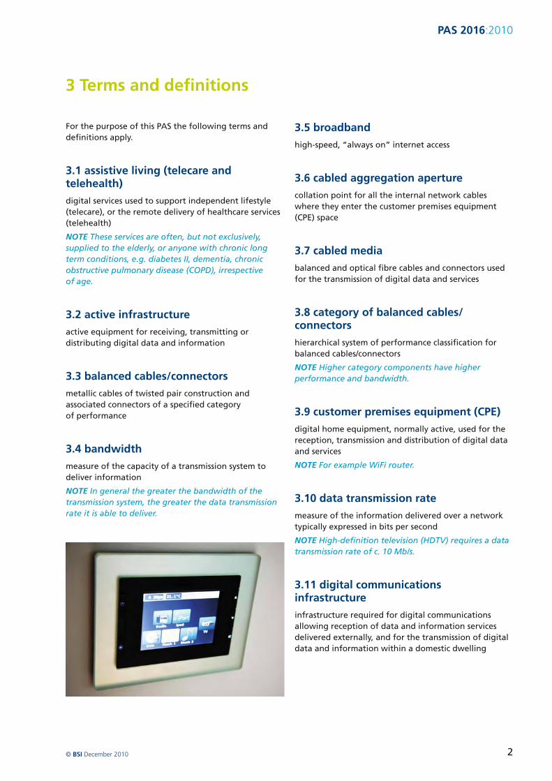
PAS 20162010
312 fibre optic
transmission technology that allows for the transmission of digital data by light pulses using optical fibre cable and fibre optic connecting hardware
NOTE Optical fibre can be either glass or plastic
313 home distributor (HD) panel
equipment for interconnecting data ports by means of short connecting cables or cords
NOTE For example a switch (an active device) to be connected with the required output socket normally using equipment cords
314 internet service provider
commercial supplier of digital content and services
315 local area network (LAN)
main distribution point that connects to a main street cabinet and then to a jointing chamber which provides the final link to the external wall of the dwelling
NOTE The internal network within the dwelling together with equipment such as routers (outside the scope of this PAS) also form part of the LAN
316 network termination point (NTP)
final connection point and demarcation between the external and internal networks and installed by the supplier
NOTE Beyond this point the developer builder or occupier has liability for the digital infrastructure
317 optical fibre cables and fibre optic connectors
all-silica (glass) or plastic fibre optic cables and associated connectors
318 passive infrastructure
non-active parts of the digital infrastructure
NOTE This includes cables and outlet sockets and contain no active elements
319 power line communications (PLC)
use of electrical power cables for the distribution of digital data and content
320 residential gateway
device combining in one unit a number of active pieces of equipment for the distribution of digital data and content and an access network interface
321 service provider
telecommunications operator or other entity responsible for the connection of a household to the global internet
322 star topology
network where digital service outlets are connected to a common central point
NOTE For example in home networks the residential gateway or switch by dedicated connections
323 supplier
provider of digital infrastructure services or both
324 router
primary active equipment interfacing external and internal networks of a dwelling and connecting digital devices in the home to form an internal network
NOTE 1 There may be more than one switch needed in an internal network
NOTE 2 It is often integrated into the residential gateway
325 wireless deadspot
location in a building or the built environment where the reception of wireless signals is not possible because of signal blocking or other interference
326 wireless links
use of radio transmissions to carry digital data
copy BSI December 2010 3
PAS 20162010
4 Domestic dwelling digital infrastructure
41 General
The objective of a domestic dwelling digital infrastructure is to provide
a) broadband connectivity to the internet and
b) distribution network for the reception and transmission of digital signals and services throughout the dwelling These services may or may not involve an access connection ie there can be services which are solely confined to the dwelling
NOTE For example home entertainment energy services telecare and telehealth services ndash referred to as assistive living services
NOTE 1 The objective of the Coalition Government is to ensure the UK has the best superfast broadband network in Europe by 2015 through market deployment or through strategic intervention in areas the market will not reach In doing so the Coalition also aims to achieve in virtually every home access to a minimum of 2 Mbs broadband connectivity In new build homes 2 Mbs is a lower bound Up to 24 Mbs is already the standard in respect of asymmetric digital subscriber line (ADSL) very high speed digital subscriber line (VDSL) from the street cabinet will increase this Hybrid Fibre Coax Networks already deliver up to 50 Mbs New build infrastructure can be designed to support rates far greater than these data rates eg 100 Mbs
In densely populated urban areas this is unlikely to be a problem while in remote rural areas without a cabled connection achieving this bandwidth can be challenging
Next generation distribution systems in new build homes should be able to support 2 Mbs transmissions but also have a much higher capability so they can handle the likely increases to Mbs This high data rate can only be reliably supported on a cabled infrastructure
Within the dwelling balanced cabling is the most practical medium with optical fibre cabling being considered as an optional addition for future installations
For new build dwellings a cabled medium should be used as the transmission medium of preference
Most users are likely to use wireless distribution in addition to the fixed infrastructure with the
latter primarily being used for the most demanding applications eg video distribution especially high definition and video on demand
Wireless provides convenience and offers the possibility of connecting to the internet from any place in the dwelling provided there are no wireless deadspots However cabled medium is required to connect wireless routers to the Internet Wireless connectivity is assumed in this PAS to provide a supplementary method of connectivity to broadband services used in conjunction with cabled media
In the context of new build domestic dwellings providing free access to cable routes then power line communications are unlikely to be a major consideration Although power line communications are an alternative option in the context of existing properties and refurbishment this is beyond the scope of this PAS
All dwellings are likely to have digital terrestrial or satellite TV connectivity or both These requirements should be included in the specification of the home network providing digital interconnectivity between such TVs and associated for example programmable video recorders (PVRs) Digital video disc (DVD) and Blu-ray players other digital devices within the home and the ldquoresidential gatewayrdquo
copy BSI December 2010 4
PAS 20162010
5 Boundary between internal and external infrastructure
51 General
This PAS describes the external and internal digital infrastructures separately The division between the two is defined by the demarcation point a legally defined point in the provision of telecommunications services at which responsibility for the infrastructure passes from the service provider to the householder The demarcation point is defined differently in different countries In the UK there will be active or passive (ie un-powered or powered) NTP which belongs to the telecommunications provider and which isolates the incoming connection from the customerrsquos equipment (see Figure 1)
In UK new build homes the following should be considered for the external infrastructure including
a) there is an individual connection (metallic or optical fibre) to an individual dwelling from the service providerrsquos equipment external to the curtilage of the dwelling In this case the demarcation point
will be at or within the boundary of the curtilage of the dwelling
b) there is a connection to the individual dwelling but this is provided from the service providerrsquos equipment installed in a location owned and or managed by the organization responsible for common parts
NOTE For example a building or estate management company
c)the service provider delivers service to a demarcation point external to individual dwellings and final distribution is managed by an organization responsible for common parts An example of this would be an estate or municipality that wishes to provide its own local digital infrastructure In such cases a secondary demarcation point will exist for each attached dwelling
copy BSI December 2010 5
PAS 20162010
Figure 1 ndash Domestic digital installations
Digital cupboard
Property boundary
NTP
Cust
omer
hub
Patc
h le
ads
Patc
h pa
nel
Cat
5e c
able
s Outlet
Outlet
Demarcation point
Outlet
copy BSI December 2010 6
PAS 20162010
52 Liability
This PAS is focused on the internal digital infrastructure contained within the bounding walls of the dwelling and gives guidance on the external connection from the jointing chamber This is the most immediate external connection point linking the dwelling infrastructure with the external networks most often it is located in the street beyond the curtilege of the property
The reason for the distinction between external and internal digital infrastructure is that up to the NTP liability rests with the infrastructure installer or ISP
Figure 2 ndash Generic zones of liability
Beyond the external termination point liability for the internal digital infrastructure lies with the builder developer or customer unless installed by the service provider
However ultimate liability for the internal network remains with the householder even if he contracts that to another entity
The generic zones of liability for a typical single dwelling unit are shown in Figure 2
Builder developer liability
Builder developer or customer responsibility
ISP telecommunications company or infrastructure contractorrsquos liability
Jointing chamber
ISP telecommunications ISP liability company or infrastructure contractorrsquos liability
Main district server room
Estate distribution point
copy BSI December 2010 7
PAS 20162010
6 External infrastructure
61 Local Area Network (LAN) connections
The connection of a domestic dwelling to an external digital network is the end of point of the external Local Area Network (LAN) with the internal network also being an LAN or home network The demarcation point between external and internal networks is the NTP
In the local area the main distribution point for the external LAN should be an exchange or a server room This connects to a main street cabinet (primary connection point) and then to a jointing chamber which provides the final link to the external wall of the dwelling
62 Connection to the external wall of the property
For all telecommunication services a NTP should be installed internally or externally to allow entry of the data infrastructure into the home
NOTE See CLG guidance on data ducting for new homes which describes best practice in relation to external entry into new homes [1]
The NTP is the demarcation point between the providerrsquos external network and the developer customer-provided cabling All internal cabling beyond the NTP should be the responsibility of the builder customer and after handover the customer
copy BSI December 2010 8
PAS 20162010
7 Internal digital infrastructure
71 Overview
Internal digital infrastructure should consist of both cabled and wireless elements
The design of generic information technology cabling in homes is specified in BS EN 50173-4 The specification of those installations and their quality assurance is specified in BS EN 50174-1 Particular requirements for installation planning and practices in homes are specified in BS EN 50174-2
BS EN 50173-4 requires that cabling be implemented in a star configuration from a home distributor (HD) located in a ldquoprimary distribution spacerdquo which is separately specified in BS EN 50174-2 Exceptionally for large buildings additional star points [secondary home distributors (SHDs)] may be used to serve areas of the building not easily served by the primary star point Where possible the demarcation point should be co-located with the HD
The installation of unscreened balanced cabling components of Category 5 should be installed in accordance with BS EN 50173-1 (equivalent to Category 5e of ANSI-TIA-568-C2) which also meets the minimum implementation of BS EN 50173-4
A star topology is a network where the data outlets are connected to a common central point in home networks the residential gateway or switch by dedicated connections The main benefits of a star network is reliability ndash if one of the ldquopoint-to-pointrdquo segments is broken only the devices on that link will be affected and not affect other devices on other arms of the star
72 External to internal connection ndash Houses and multi-dwelling units
The ducting should be laid from the footway jointing chamber (with the socket end presented to the joint box) and terminate with a pre-formed 90deg bend at the outside of the house wall The duct runs should be kept to a minimum depth of cover of 350 mm beneath the proposed finish level (450 mm under a soft surface)
20 mm electrical conduit should be supplied and installed through the cavity wall at a point vertically above the end of the service duct A back box or single-gang flush steel box should be installed in
preparation for the installer to fit and commission the connection to the active digital equipment eg switch or other type of main socket
All ducts should be provided with a draw rope after installation unless local agreement is made to substitute the draw rope for lead-in cable 1 m at the house and 3 m at the tail in the chamber should be left
The service duct should be cut level two bricks below the damp proof course it should be sealed at both ends using a duct plug to prevent ingress of debris
copy BSI December 2010 9
PAS 20162010
73 Primary distribution space
731 Accommodation
In each dwelling the cabled CPE the presentation of the home cabling and associated equipment should be accommodated in a primary distribution space as specified in BS EN 50174-2 which is secure (lockable)
This space should be located in for example an under-stairs cupboard or a similar location
The primary distribution space should be provided with two-twin gang switched 13A sockets installed in accordance with BS 7671
When designing the house installation sufficient dimensions for the cable aggregation aperture should be designed-in ndash to the point where all cables and ducts enter the equipment space An aperture diameter of 50 mm is adequate in most cases
On exiting the primary distribution space
a) BS EN 50174-2 requires that the pathway between the dwelling entrance and the primary distribution space shall have a cross-section equivalent to a minimum diameter of 38 mm (consistent with Size 40 conduits of BS EN 61386 series)
b) BS EN 50174-2 requires that the pathway between the primary distribution space and the outlets shall have a cross-section equivalent to a minimum diameter of 16 mm (consistent with Size 20 conduits of BS EN 61386 series)
The location should allow for ease of connection and maintenance access between the incoming service duct and the termination at the CPE The location of the primary distribution space should be agreed early in the design of the dwellings
copy BSI December 2010 10
PAS 20162010
The space should be located to avoid extremes of temperature and humidity The standard ambient temperature range is 0 degC - 44 degC Humidity should be kept within a range to avoid the risk of condensation
The equipment may be mounted in a 19 in rack or other suitable mounting system including wall mounted sockets Where used the rack system can be floor mounted or wall mounted There should be sufficient capacity to allow for expansion of the number of wall sockets throughout the house to provide two twin outlets per room excluding bathrooms and toilets
NOTE This may not comply with the recommendations of BS EN 50173-4 for large rooms but may over-provide for smaller rooms and is judged to provide a good guide
All cabinets frames or racks accommodated within the primary distribution space should be earthed in accordance with BS 6701 Any power supply cabling provided to these cabinets frames or racks should be carried out in accordance with BS 7671
732 Customer premises equipment (CPE)
The initial CPE should provide sufficient outlet ports to service
a) two telephone points and
b) four independent data service outlets on the switch or residential gateway
733 Presentation of home cabling
The outlets terminating the home cabling should be mounted on a panel(s) to allow interconnection to CPE and where appropriate to other outlets on the panel(s)
74 Premises distribution cabling
741 General provision
In the case of all internal cabling it is essential that the developer designs the cable routes and socket placements to achieve the maximum capability for the delivery of multiple services to all main rooms
NOTE This way all the benefits offered by the network can be realized
Pathways should be provided throughout the home to provide each room two twin outlets per room excluding bathrooms and toilets The required pathways should be carried out in accordance with 731
The developer should install cabling for data services using cables and connectors in accordance with 742
For ldquoconnectedrdquo (digitally wired) homes there should be as a minimum data outlets in the lounge master bedroom and study locations and also to each location where a co-axial socket is deployed for TV services
In this way multiple services such as high speed Internet or broadband TV content can be delivered simultaneously A star wire configuration should connect each room in the dwelling using the ceiling rose as the primary connection point in each room This provides an ease of access for dropping communications cables to any location in the room
Data outlet sockets should be mounted in the range 700 ndash 900 mm [2] This is for ease of access for people in wheelchairs and on the ground floor to help reduce damage in the event of floods
742 Cables and connectors
Balanced cables should be unscreened Category 5 in accordance with BS EN 50173-1 (which are equivalent to the unshielded Category 5e cables of ANSI-TIA-568-C2)
The maximum length of the cables should be 90 m in accordance with the reference implementations of BS EN 50173-4 or ANSI-TIA-568-C2 respectively
The presentation of the home cabling at the HD and the wall sockets distributed through the home should be in accordance with BS EN 60603-7 (commonly but inaccurately referred to as RJ45) As specified for telecommunications outlets in BS EN 50173-4 these connectors should be of the same type (ie unscreened or screened) and category as the balanced cable The termination of the cable at those outlets should be as shown in Figure 3
NOTE Unscreened category 5 connectors are specified in BS EN 60603-7-2 Higher category of unscreened and screened connectors are specified in other parts of the BS EN 60603-7 standards series
copy BSI December 2010 11
PAS 20162010
Figure 3 ndash Pin grouping and pair assignments for BS EN 60603-7 series connecting hardware (front view of connector)
1 2 3 4 5 6 7 8
743 Data cable runs
Balanced cables should be kept at a minimum separation of 50 mm from mains power cables
NOTE BS 7671 delegates the requirements for separationsegregation between power supply and telecommunications cabling to BS 6701 (for safety protection) and to BS EN 50174-2 (for suppression of electrical interference) This PAS may comply with these requirements provided that the power supply cable (or bundle of cables) is not carrying in excess of 100 amps
The user of this PAS is recommended to comply with the wider requirements of BS 6701 and BS EN 50174-2 where this separation cannot be maintained
744 Wireless connectivity
Wireless can also be deployed enabling mobility around the home An end-user may choose to collocate an ISPrsquos residential gateway either at the cabled CPE location (leading to further ISP fan out over the star wired data sockets) or at the end of any of the 4 times star wired data sockets
NOTE 1 For example the ISPrsquos residential gateway may be deployed in a home office
NOTE 2 Wireless networking may form part of the ldquofinal legrdquo of the home network where it provides a reasonable alternative to physical cabling to data points
The location of wireless access points should be tested to ensure the effectiveness of their transmission and reception and that they are not located in a wireless deadspot
745 Blank data sockets and cable ducting
7451 Blank data sockets
The minimum number of recommended cabled data sockets per house is four At least one double back box and blanking plate should be located in each room in the house excluding bathrooms toilets and storage cupboards
Each blank double data socket should be mounted close to double socket power outlets in accordance with BS 7671
7452 Cable ducting
Cable ducting provides an open infrastructure to accept current or future cabling solutions throughout the dwelling This allows quick and easy expansion or upgrade during the life of the building with no impact or damage to the physical structure or decorative finishes
Ducting should be laid from the central distribution point the CPE space to every power socket in the premise at the same time as providing the power cabling to each socket
NOTE 1 BS EN 50174-2 requires that the pathway between the primary distribution space and the outlets have a cross-section equivalent to a minimum diameter of 16 mm (consistent with Size 20 conduits of BS EN 61386 series)
Duct is most often supplied on standard reels with a pre-installed pull-cord and secure end plugs These plugs protect against ingress of dirt and other contamination To lock the pull-cord in position to prevent accidental pull-out these plugs should be retained and refitted to the installed duct and remaining unused duct
The installer should carry a supply of end plugs to cap off duct that has been installed in the home until the duct is populated with cables The installer should satisfy himself that the duct is clean and suitable for use or scrap the remaining product
NOTE 2 The viability of stored duct without plugs is suspect
The duct can be routed across walls or along timber studs and joists and fixed using standard cabling clips and ties using conventional installation practices
copy BSI December 2010 12
PAS 20162010
The duct should not be routed under or between moveable services or other objects that could cause crushing
The duct may be buried in plaster or floor screeds
The minimum recommended bend radius should typically be 150 mm but in all cases the manufacturersrsquo specification should be adhered to
A double sweep should be used when negotiating internal or external corners as shown in Figure 4
Figure 4 ndash Cable ducting diagram
Capped power cable feed to double gang power sockets
Power socket with plastic optical fibre (POF) media converter and Ethernet RJ45 data socket
Duct containing plastic optical fibre (POF) from ethernet hub
All ducts radiate from central distribution hub adjacent to ethernet hub
Source Miniflex
After populating the duct with the required data cables foam plugs should be fitted into the annular gap at both ends to prevent ingress of dust or insects
746 Fire resistance
NOTE Attention is drawn to all elements of the digital infrastructure installation with the appropriate fire regulations for domestic dwellings
Twin RJ45 ethernet data
Double gang power socket with empty feed for future data upgrade
Twin ducts containing category 5 copper cables from ethernet hub
150 mm radius
copy BSI December 2010 13
PAS 20162010
8 Installation testing
The completed infrastructure installation should be tested as fully operational The results of the tests should be documented and included with the documentation passed to the homeowner or occupier
NOTE The responsibility for testing the installation lies with the installing contractor
The balanced cabling from the home distributor to the telecommunication outlets should be tested in accordance with BS EN 50346 to confirm that the transmission performance meets the permanent link requirements of Class D of BS EN 50173-1 (or Category 5e of ANSI-TIA-568-C2)
All-silica optical fibre cabling from the home distributor to the telecommunication outlets should be tested in accordance with BS EN 50346 to confirm that the transmission performance meets the permanent link requirements of BS EN 50173-1 (or ANSI-TIA-568-C0)
Plastic optical fibre cabling from the home distributor to the telecommunication outlets should be tested in accordance with BS EN 50346 to confirm that the transmission performance meets the permanent link requirements of BS EN 50173-1
copy BSI December 2010 14
PAS 20162010
9 Documentation and handover
All outlets at the home distributor and throughout the dwelling should be clearly labelled in accordance with BS EN 50174-1
The labelling of outlet sockets face-plates will be unacceptable if located on the exposed face of the socket The label should be fixed within the faceplate back box The labelling should be firmly located to ensure it is not displaced when the faceplate is removed
The location dimensions andor capacity of pathways into which information technology cabling has been
installed should be recorded together with details of any mitigation measures applied to provide the required environment in accordance with BS EN 50174-1 These recordings should include the position of the CPE equipment within the primary distribution space
This documentation should be passed to the occupier of the property when they move into the dwelling
The documentation should include digital installation instructions and should be passed to subsequent occupiers
copy BSI December 2010 15
PAS 20162010
Bibliography
Standards publications
BS EN 61386ndash 1 Conduit systems for cable management ndash Part 1 General requirements
BS EN 61386ndash 21 Conduit systems for cable management ndash Particular requirements ndash Part 21 Rigid conduit systems
BS EN 61386ndash 22 Conduit systems for cable management ndash Particular requirements ndash Part 22 Pliable conduit systems
BS EN 61386ndash 23 Conduit systems for cable management ndash Particular requirements ndash Part 23 Flexible conduit systems
BS EN 61386ndash 24 Conduit systems for cable management ndash Particular requirements ndash Part 24 Conduit systems buried underground
Other publications
[1] Data Ducting Infrastructure for New Homes Guidance Note CLG March 2008
[2] Stephen Thorpe and Habinteg Housing Association Wheelchair housing design guide (2nd edition) BRE Press February 2006
Further reading
BS EN 50174-3 Information technology ndash Cabling installation ndash Part 3 Installation planning and practices outside buildings
BT Openreach ndash Buildersrsquo Guide to telecommunications infrastructure and installation May 2007
NICC Report April 2010 (full reference to be confirmed)
National Joint Utilities Group ndash Guidelines On The Positioning And Colour Coding Of Utilitiesrsquo Apparatus NJUG April 2003
copy BSI December 2010 16
PAS 20162010
BSI ndash British Standards Institution
BSI is the independent national body responsible for preparing British Standards
It presents the UK view on standards in Europe and at the international level
It is incorporated by Royal Charter
Revisions British Standards are updated by amendment or revision Users of British Standards should make sure that they possess the latest amendments or editions
It is the constant aim of BSI to improve the quality of our products and services We would be grateful if anyone finding an inaccuracy or ambiguity while using this Publicly Available Specification would inform the Information Centre
Tel +44 (0)20 8996 7111 Fax +44 (0)20 8996 7048 Email infobsigroupcom
BSI offers members an individual updating service called PLUS which ensures that subscribers automatically receive the latest editions of standards
Buying standards Orders for all BSI international and foreign standards publications should be addressed to Customer Services
Tel +44 (0)20 8996 9001 Fax +44 (0)20 8996 7001 Email ordersbsigroupcom
Standards are also available from the BSI website at wwwbsigroupcomshop
Information on standards BSI provides a wide range of information on national European and international standards through its Library Various BSI electronic information services are also available which give details on all its products and services Contact the Information Centre
Tel +44 (0)20 8996 7111 Fax +44 (0)20 8996 7048 Email infobsigroupcom
Subscribing members of BSI are kept up to date with standards developments and receive substantial discounts on the purchase price of standards For details of these and other benefits contact Membership Administration
Tel +44 (0)20 8996 7002 Fax +44 (0)20 8996 7047 Email membershipbsigroupcom
Information regarding online access to British Standards via British Standards Online can be found at wwwbsigroupcombsol
Further information about BSI is available on the BSI website at wwwbsigroupcom
Copyright Copyright subsists in all BSI publications BSI also holds the copyright in the UK of the publications of the international standardization bodies Except as permitted under the Copyright Designs and Patents Act 1988 no extract may be reproduced stored in a retrieval system or transmitted in any form or by any means ndash electronic photocopying recording or otherwise ndash without prior written permission from BSI
This does not preclude the free use in the course of implementing the standard of necessary details such as symbols and size type or grade designations If these details are to be used for any other purpose than implementation then the prior written permission of BSI must be obtained
Details and advice can be obtained from the Licensing Department
Tel +44 (0)20 8996 7070 Fax +44 (0)20 8996 7512 Email copyrightbsigroupcom
copy BSI December 2010 17
British Standards Institution 389 Chiswick High Road London W4 4AL United Kingdom
wwwbsigroupcom
ISBN 978shy0shy580shy67917shy9
9 780580 679179
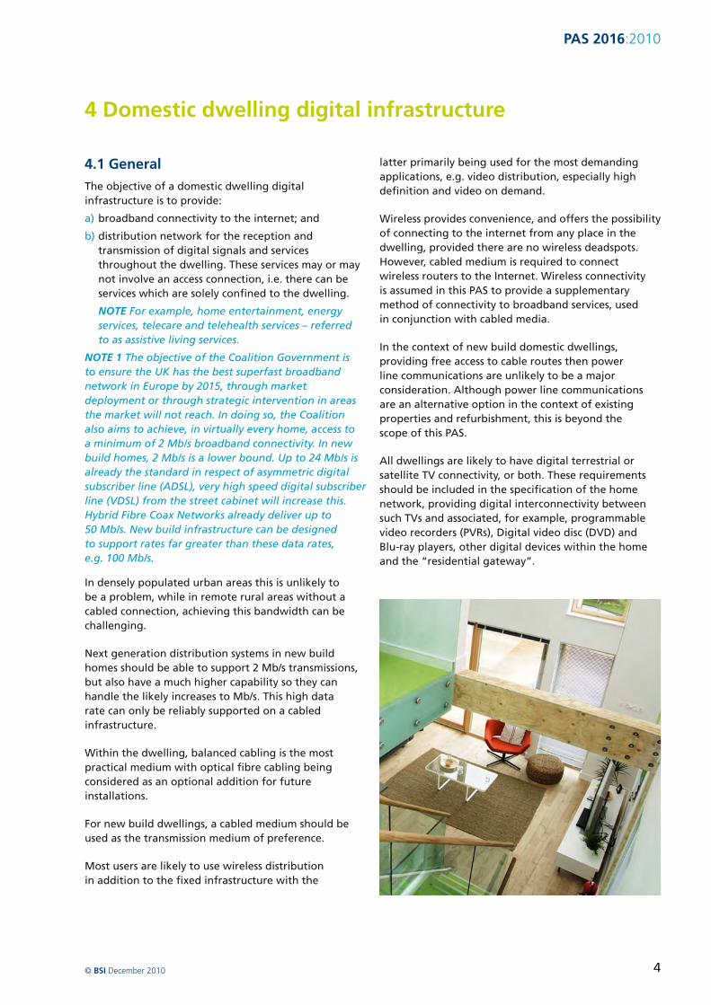
PAS 20162010
5 Boundary between internal and external infrastructure
51 General
This PAS describes the external and internal digital infrastructures separately The division between the two is defined by the demarcation point a legally defined point in the provision of telecommunications services at which responsibility for the infrastructure passes from the service provider to the householder The demarcation point is defined differently in different countries In the UK there will be active or passive (ie un-powered or powered) NTP which belongs to the telecommunications provider and which isolates the incoming connection from the customerrsquos equipment (see Figure 1)
In UK new build homes the following should be considered for the external infrastructure including
a) there is an individual connection (metallic or optical fibre) to an individual dwelling from the service providerrsquos equipment external to the curtilage of the dwelling In this case the demarcation point
will be at or within the boundary of the curtilage of the dwelling
b) there is a connection to the individual dwelling but this is provided from the service providerrsquos equipment installed in a location owned and or managed by the organization responsible for common parts
NOTE For example a building or estate management company
c)the service provider delivers service to a demarcation point external to individual dwellings and final distribution is managed by an organization responsible for common parts An example of this would be an estate or municipality that wishes to provide its own local digital infrastructure In such cases a secondary demarcation point will exist for each attached dwelling
copy BSI December 2010 5
PAS 20162010
Figure 1 ndash Domestic digital installations
Digital cupboard
Property boundary
NTP
Cust
omer
hub
Patc
h le
ads
Patc
h pa
nel
Cat
5e c
able
s Outlet
Outlet
Demarcation point
Outlet
copy BSI December 2010 6
PAS 20162010
52 Liability
This PAS is focused on the internal digital infrastructure contained within the bounding walls of the dwelling and gives guidance on the external connection from the jointing chamber This is the most immediate external connection point linking the dwelling infrastructure with the external networks most often it is located in the street beyond the curtilege of the property
The reason for the distinction between external and internal digital infrastructure is that up to the NTP liability rests with the infrastructure installer or ISP
Figure 2 ndash Generic zones of liability
Beyond the external termination point liability for the internal digital infrastructure lies with the builder developer or customer unless installed by the service provider
However ultimate liability for the internal network remains with the householder even if he contracts that to another entity
The generic zones of liability for a typical single dwelling unit are shown in Figure 2
Builder developer liability
Builder developer or customer responsibility
ISP telecommunications company or infrastructure contractorrsquos liability
Jointing chamber
ISP telecommunications ISP liability company or infrastructure contractorrsquos liability
Main district server room
Estate distribution point
copy BSI December 2010 7
PAS 20162010
6 External infrastructure
61 Local Area Network (LAN) connections
The connection of a domestic dwelling to an external digital network is the end of point of the external Local Area Network (LAN) with the internal network also being an LAN or home network The demarcation point between external and internal networks is the NTP
In the local area the main distribution point for the external LAN should be an exchange or a server room This connects to a main street cabinet (primary connection point) and then to a jointing chamber which provides the final link to the external wall of the dwelling
62 Connection to the external wall of the property
For all telecommunication services a NTP should be installed internally or externally to allow entry of the data infrastructure into the home
NOTE See CLG guidance on data ducting for new homes which describes best practice in relation to external entry into new homes [1]
The NTP is the demarcation point between the providerrsquos external network and the developer customer-provided cabling All internal cabling beyond the NTP should be the responsibility of the builder customer and after handover the customer
copy BSI December 2010 8
PAS 20162010
7 Internal digital infrastructure
71 Overview
Internal digital infrastructure should consist of both cabled and wireless elements
The design of generic information technology cabling in homes is specified in BS EN 50173-4 The specification of those installations and their quality assurance is specified in BS EN 50174-1 Particular requirements for installation planning and practices in homes are specified in BS EN 50174-2
BS EN 50173-4 requires that cabling be implemented in a star configuration from a home distributor (HD) located in a ldquoprimary distribution spacerdquo which is separately specified in BS EN 50174-2 Exceptionally for large buildings additional star points [secondary home distributors (SHDs)] may be used to serve areas of the building not easily served by the primary star point Where possible the demarcation point should be co-located with the HD
The installation of unscreened balanced cabling components of Category 5 should be installed in accordance with BS EN 50173-1 (equivalent to Category 5e of ANSI-TIA-568-C2) which also meets the minimum implementation of BS EN 50173-4
A star topology is a network where the data outlets are connected to a common central point in home networks the residential gateway or switch by dedicated connections The main benefits of a star network is reliability ndash if one of the ldquopoint-to-pointrdquo segments is broken only the devices on that link will be affected and not affect other devices on other arms of the star
72 External to internal connection ndash Houses and multi-dwelling units
The ducting should be laid from the footway jointing chamber (with the socket end presented to the joint box) and terminate with a pre-formed 90deg bend at the outside of the house wall The duct runs should be kept to a minimum depth of cover of 350 mm beneath the proposed finish level (450 mm under a soft surface)
20 mm electrical conduit should be supplied and installed through the cavity wall at a point vertically above the end of the service duct A back box or single-gang flush steel box should be installed in
preparation for the installer to fit and commission the connection to the active digital equipment eg switch or other type of main socket
All ducts should be provided with a draw rope after installation unless local agreement is made to substitute the draw rope for lead-in cable 1 m at the house and 3 m at the tail in the chamber should be left
The service duct should be cut level two bricks below the damp proof course it should be sealed at both ends using a duct plug to prevent ingress of debris
copy BSI December 2010 9
PAS 20162010
73 Primary distribution space
731 Accommodation
In each dwelling the cabled CPE the presentation of the home cabling and associated equipment should be accommodated in a primary distribution space as specified in BS EN 50174-2 which is secure (lockable)
This space should be located in for example an under-stairs cupboard or a similar location
The primary distribution space should be provided with two-twin gang switched 13A sockets installed in accordance with BS 7671
When designing the house installation sufficient dimensions for the cable aggregation aperture should be designed-in ndash to the point where all cables and ducts enter the equipment space An aperture diameter of 50 mm is adequate in most cases
On exiting the primary distribution space
a) BS EN 50174-2 requires that the pathway between the dwelling entrance and the primary distribution space shall have a cross-section equivalent to a minimum diameter of 38 mm (consistent with Size 40 conduits of BS EN 61386 series)
b) BS EN 50174-2 requires that the pathway between the primary distribution space and the outlets shall have a cross-section equivalent to a minimum diameter of 16 mm (consistent with Size 20 conduits of BS EN 61386 series)
The location should allow for ease of connection and maintenance access between the incoming service duct and the termination at the CPE The location of the primary distribution space should be agreed early in the design of the dwellings
copy BSI December 2010 10
PAS 20162010
The space should be located to avoid extremes of temperature and humidity The standard ambient temperature range is 0 degC - 44 degC Humidity should be kept within a range to avoid the risk of condensation
The equipment may be mounted in a 19 in rack or other suitable mounting system including wall mounted sockets Where used the rack system can be floor mounted or wall mounted There should be sufficient capacity to allow for expansion of the number of wall sockets throughout the house to provide two twin outlets per room excluding bathrooms and toilets
NOTE This may not comply with the recommendations of BS EN 50173-4 for large rooms but may over-provide for smaller rooms and is judged to provide a good guide
All cabinets frames or racks accommodated within the primary distribution space should be earthed in accordance with BS 6701 Any power supply cabling provided to these cabinets frames or racks should be carried out in accordance with BS 7671
732 Customer premises equipment (CPE)
The initial CPE should provide sufficient outlet ports to service
a) two telephone points and
b) four independent data service outlets on the switch or residential gateway
733 Presentation of home cabling
The outlets terminating the home cabling should be mounted on a panel(s) to allow interconnection to CPE and where appropriate to other outlets on the panel(s)
74 Premises distribution cabling
741 General provision
In the case of all internal cabling it is essential that the developer designs the cable routes and socket placements to achieve the maximum capability for the delivery of multiple services to all main rooms
NOTE This way all the benefits offered by the network can be realized
Pathways should be provided throughout the home to provide each room two twin outlets per room excluding bathrooms and toilets The required pathways should be carried out in accordance with 731
The developer should install cabling for data services using cables and connectors in accordance with 742
For ldquoconnectedrdquo (digitally wired) homes there should be as a minimum data outlets in the lounge master bedroom and study locations and also to each location where a co-axial socket is deployed for TV services
In this way multiple services such as high speed Internet or broadband TV content can be delivered simultaneously A star wire configuration should connect each room in the dwelling using the ceiling rose as the primary connection point in each room This provides an ease of access for dropping communications cables to any location in the room
Data outlet sockets should be mounted in the range 700 ndash 900 mm [2] This is for ease of access for people in wheelchairs and on the ground floor to help reduce damage in the event of floods
742 Cables and connectors
Balanced cables should be unscreened Category 5 in accordance with BS EN 50173-1 (which are equivalent to the unshielded Category 5e cables of ANSI-TIA-568-C2)
The maximum length of the cables should be 90 m in accordance with the reference implementations of BS EN 50173-4 or ANSI-TIA-568-C2 respectively
The presentation of the home cabling at the HD and the wall sockets distributed through the home should be in accordance with BS EN 60603-7 (commonly but inaccurately referred to as RJ45) As specified for telecommunications outlets in BS EN 50173-4 these connectors should be of the same type (ie unscreened or screened) and category as the balanced cable The termination of the cable at those outlets should be as shown in Figure 3
NOTE Unscreened category 5 connectors are specified in BS EN 60603-7-2 Higher category of unscreened and screened connectors are specified in other parts of the BS EN 60603-7 standards series
copy BSI December 2010 11
PAS 20162010
Figure 3 ndash Pin grouping and pair assignments for BS EN 60603-7 series connecting hardware (front view of connector)
1 2 3 4 5 6 7 8
743 Data cable runs
Balanced cables should be kept at a minimum separation of 50 mm from mains power cables
NOTE BS 7671 delegates the requirements for separationsegregation between power supply and telecommunications cabling to BS 6701 (for safety protection) and to BS EN 50174-2 (for suppression of electrical interference) This PAS may comply with these requirements provided that the power supply cable (or bundle of cables) is not carrying in excess of 100 amps
The user of this PAS is recommended to comply with the wider requirements of BS 6701 and BS EN 50174-2 where this separation cannot be maintained
744 Wireless connectivity
Wireless can also be deployed enabling mobility around the home An end-user may choose to collocate an ISPrsquos residential gateway either at the cabled CPE location (leading to further ISP fan out over the star wired data sockets) or at the end of any of the 4 times star wired data sockets
NOTE 1 For example the ISPrsquos residential gateway may be deployed in a home office
NOTE 2 Wireless networking may form part of the ldquofinal legrdquo of the home network where it provides a reasonable alternative to physical cabling to data points
The location of wireless access points should be tested to ensure the effectiveness of their transmission and reception and that they are not located in a wireless deadspot
745 Blank data sockets and cable ducting
7451 Blank data sockets
The minimum number of recommended cabled data sockets per house is four At least one double back box and blanking plate should be located in each room in the house excluding bathrooms toilets and storage cupboards
Each blank double data socket should be mounted close to double socket power outlets in accordance with BS 7671
7452 Cable ducting
Cable ducting provides an open infrastructure to accept current or future cabling solutions throughout the dwelling This allows quick and easy expansion or upgrade during the life of the building with no impact or damage to the physical structure or decorative finishes
Ducting should be laid from the central distribution point the CPE space to every power socket in the premise at the same time as providing the power cabling to each socket
NOTE 1 BS EN 50174-2 requires that the pathway between the primary distribution space and the outlets have a cross-section equivalent to a minimum diameter of 16 mm (consistent with Size 20 conduits of BS EN 61386 series)
Duct is most often supplied on standard reels with a pre-installed pull-cord and secure end plugs These plugs protect against ingress of dirt and other contamination To lock the pull-cord in position to prevent accidental pull-out these plugs should be retained and refitted to the installed duct and remaining unused duct
The installer should carry a supply of end plugs to cap off duct that has been installed in the home until the duct is populated with cables The installer should satisfy himself that the duct is clean and suitable for use or scrap the remaining product
NOTE 2 The viability of stored duct without plugs is suspect
The duct can be routed across walls or along timber studs and joists and fixed using standard cabling clips and ties using conventional installation practices
copy BSI December 2010 12
PAS 20162010
The duct should not be routed under or between moveable services or other objects that could cause crushing
The duct may be buried in plaster or floor screeds
The minimum recommended bend radius should typically be 150 mm but in all cases the manufacturersrsquo specification should be adhered to
A double sweep should be used when negotiating internal or external corners as shown in Figure 4
Figure 4 ndash Cable ducting diagram
Capped power cable feed to double gang power sockets
Power socket with plastic optical fibre (POF) media converter and Ethernet RJ45 data socket
Duct containing plastic optical fibre (POF) from ethernet hub
All ducts radiate from central distribution hub adjacent to ethernet hub
Source Miniflex
After populating the duct with the required data cables foam plugs should be fitted into the annular gap at both ends to prevent ingress of dust or insects
746 Fire resistance
NOTE Attention is drawn to all elements of the digital infrastructure installation with the appropriate fire regulations for domestic dwellings
Twin RJ45 ethernet data
Double gang power socket with empty feed for future data upgrade
Twin ducts containing category 5 copper cables from ethernet hub
150 mm radius
copy BSI December 2010 13
PAS 20162010
8 Installation testing
The completed infrastructure installation should be tested as fully operational The results of the tests should be documented and included with the documentation passed to the homeowner or occupier
NOTE The responsibility for testing the installation lies with the installing contractor
The balanced cabling from the home distributor to the telecommunication outlets should be tested in accordance with BS EN 50346 to confirm that the transmission performance meets the permanent link requirements of Class D of BS EN 50173-1 (or Category 5e of ANSI-TIA-568-C2)
All-silica optical fibre cabling from the home distributor to the telecommunication outlets should be tested in accordance with BS EN 50346 to confirm that the transmission performance meets the permanent link requirements of BS EN 50173-1 (or ANSI-TIA-568-C0)
Plastic optical fibre cabling from the home distributor to the telecommunication outlets should be tested in accordance with BS EN 50346 to confirm that the transmission performance meets the permanent link requirements of BS EN 50173-1
copy BSI December 2010 14
PAS 20162010
9 Documentation and handover
All outlets at the home distributor and throughout the dwelling should be clearly labelled in accordance with BS EN 50174-1
The labelling of outlet sockets face-plates will be unacceptable if located on the exposed face of the socket The label should be fixed within the faceplate back box The labelling should be firmly located to ensure it is not displaced when the faceplate is removed
The location dimensions andor capacity of pathways into which information technology cabling has been
installed should be recorded together with details of any mitigation measures applied to provide the required environment in accordance with BS EN 50174-1 These recordings should include the position of the CPE equipment within the primary distribution space
This documentation should be passed to the occupier of the property when they move into the dwelling
The documentation should include digital installation instructions and should be passed to subsequent occupiers
copy BSI December 2010 15
PAS 20162010
Bibliography
Standards publications
BS EN 61386ndash 1 Conduit systems for cable management ndash Part 1 General requirements
BS EN 61386ndash 21 Conduit systems for cable management ndash Particular requirements ndash Part 21 Rigid conduit systems
BS EN 61386ndash 22 Conduit systems for cable management ndash Particular requirements ndash Part 22 Pliable conduit systems
BS EN 61386ndash 23 Conduit systems for cable management ndash Particular requirements ndash Part 23 Flexible conduit systems
BS EN 61386ndash 24 Conduit systems for cable management ndash Particular requirements ndash Part 24 Conduit systems buried underground
Other publications
[1] Data Ducting Infrastructure for New Homes Guidance Note CLG March 2008
[2] Stephen Thorpe and Habinteg Housing Association Wheelchair housing design guide (2nd edition) BRE Press February 2006
Further reading
BS EN 50174-3 Information technology ndash Cabling installation ndash Part 3 Installation planning and practices outside buildings
BT Openreach ndash Buildersrsquo Guide to telecommunications infrastructure and installation May 2007
NICC Report April 2010 (full reference to be confirmed)
National Joint Utilities Group ndash Guidelines On The Positioning And Colour Coding Of Utilitiesrsquo Apparatus NJUG April 2003
copy BSI December 2010 16
PAS 20162010
BSI ndash British Standards Institution
BSI is the independent national body responsible for preparing British Standards
It presents the UK view on standards in Europe and at the international level
It is incorporated by Royal Charter
Revisions British Standards are updated by amendment or revision Users of British Standards should make sure that they possess the latest amendments or editions
It is the constant aim of BSI to improve the quality of our products and services We would be grateful if anyone finding an inaccuracy or ambiguity while using this Publicly Available Specification would inform the Information Centre
Tel +44 (0)20 8996 7111 Fax +44 (0)20 8996 7048 Email infobsigroupcom
BSI offers members an individual updating service called PLUS which ensures that subscribers automatically receive the latest editions of standards
Buying standards Orders for all BSI international and foreign standards publications should be addressed to Customer Services
Tel +44 (0)20 8996 9001 Fax +44 (0)20 8996 7001 Email ordersbsigroupcom
Standards are also available from the BSI website at wwwbsigroupcomshop
Information on standards BSI provides a wide range of information on national European and international standards through its Library Various BSI electronic information services are also available which give details on all its products and services Contact the Information Centre
Tel +44 (0)20 8996 7111 Fax +44 (0)20 8996 7048 Email infobsigroupcom
Subscribing members of BSI are kept up to date with standards developments and receive substantial discounts on the purchase price of standards For details of these and other benefits contact Membership Administration
Tel +44 (0)20 8996 7002 Fax +44 (0)20 8996 7047 Email membershipbsigroupcom
Information regarding online access to British Standards via British Standards Online can be found at wwwbsigroupcombsol
Further information about BSI is available on the BSI website at wwwbsigroupcom
Copyright Copyright subsists in all BSI publications BSI also holds the copyright in the UK of the publications of the international standardization bodies Except as permitted under the Copyright Designs and Patents Act 1988 no extract may be reproduced stored in a retrieval system or transmitted in any form or by any means ndash electronic photocopying recording or otherwise ndash without prior written permission from BSI
This does not preclude the free use in the course of implementing the standard of necessary details such as symbols and size type or grade designations If these details are to be used for any other purpose than implementation then the prior written permission of BSI must be obtained
Details and advice can be obtained from the Licensing Department
Tel +44 (0)20 8996 7070 Fax +44 (0)20 8996 7512 Email copyrightbsigroupcom
copy BSI December 2010 17
British Standards Institution 389 Chiswick High Road London W4 4AL United Kingdom
wwwbsigroupcom
ISBN 978shy0shy580shy67917shy9
9 780580 679179
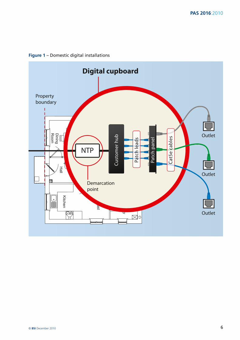
PAS 20162010
52 Liability
This PAS is focused on the internal digital infrastructure contained within the bounding walls of the dwelling and gives guidance on the external connection from the jointing chamber This is the most immediate external connection point linking the dwelling infrastructure with the external networks most often it is located in the street beyond the curtilege of the property
The reason for the distinction between external and internal digital infrastructure is that up to the NTP liability rests with the infrastructure installer or ISP
Figure 2 ndash Generic zones of liability
Beyond the external termination point liability for the internal digital infrastructure lies with the builder developer or customer unless installed by the service provider
However ultimate liability for the internal network remains with the householder even if he contracts that to another entity
The generic zones of liability for a typical single dwelling unit are shown in Figure 2
Builder developer liability
Builder developer or customer responsibility
ISP telecommunications company or infrastructure contractorrsquos liability
Jointing chamber
ISP telecommunications ISP liability company or infrastructure contractorrsquos liability
Main district server room
Estate distribution point
copy BSI December 2010 7
PAS 20162010
6 External infrastructure
61 Local Area Network (LAN) connections
The connection of a domestic dwelling to an external digital network is the end of point of the external Local Area Network (LAN) with the internal network also being an LAN or home network The demarcation point between external and internal networks is the NTP
In the local area the main distribution point for the external LAN should be an exchange or a server room This connects to a main street cabinet (primary connection point) and then to a jointing chamber which provides the final link to the external wall of the dwelling
62 Connection to the external wall of the property
For all telecommunication services a NTP should be installed internally or externally to allow entry of the data infrastructure into the home
NOTE See CLG guidance on data ducting for new homes which describes best practice in relation to external entry into new homes [1]
The NTP is the demarcation point between the providerrsquos external network and the developer customer-provided cabling All internal cabling beyond the NTP should be the responsibility of the builder customer and after handover the customer
copy BSI December 2010 8
PAS 20162010
7 Internal digital infrastructure
71 Overview
Internal digital infrastructure should consist of both cabled and wireless elements
The design of generic information technology cabling in homes is specified in BS EN 50173-4 The specification of those installations and their quality assurance is specified in BS EN 50174-1 Particular requirements for installation planning and practices in homes are specified in BS EN 50174-2
BS EN 50173-4 requires that cabling be implemented in a star configuration from a home distributor (HD) located in a ldquoprimary distribution spacerdquo which is separately specified in BS EN 50174-2 Exceptionally for large buildings additional star points [secondary home distributors (SHDs)] may be used to serve areas of the building not easily served by the primary star point Where possible the demarcation point should be co-located with the HD
The installation of unscreened balanced cabling components of Category 5 should be installed in accordance with BS EN 50173-1 (equivalent to Category 5e of ANSI-TIA-568-C2) which also meets the minimum implementation of BS EN 50173-4
A star topology is a network where the data outlets are connected to a common central point in home networks the residential gateway or switch by dedicated connections The main benefits of a star network is reliability ndash if one of the ldquopoint-to-pointrdquo segments is broken only the devices on that link will be affected and not affect other devices on other arms of the star
72 External to internal connection ndash Houses and multi-dwelling units
The ducting should be laid from the footway jointing chamber (with the socket end presented to the joint box) and terminate with a pre-formed 90deg bend at the outside of the house wall The duct runs should be kept to a minimum depth of cover of 350 mm beneath the proposed finish level (450 mm under a soft surface)
20 mm electrical conduit should be supplied and installed through the cavity wall at a point vertically above the end of the service duct A back box or single-gang flush steel box should be installed in
preparation for the installer to fit and commission the connection to the active digital equipment eg switch or other type of main socket
All ducts should be provided with a draw rope after installation unless local agreement is made to substitute the draw rope for lead-in cable 1 m at the house and 3 m at the tail in the chamber should be left
The service duct should be cut level two bricks below the damp proof course it should be sealed at both ends using a duct plug to prevent ingress of debris
copy BSI December 2010 9
PAS 20162010
73 Primary distribution space
731 Accommodation
In each dwelling the cabled CPE the presentation of the home cabling and associated equipment should be accommodated in a primary distribution space as specified in BS EN 50174-2 which is secure (lockable)
This space should be located in for example an under-stairs cupboard or a similar location
The primary distribution space should be provided with two-twin gang switched 13A sockets installed in accordance with BS 7671
When designing the house installation sufficient dimensions for the cable aggregation aperture should be designed-in ndash to the point where all cables and ducts enter the equipment space An aperture diameter of 50 mm is adequate in most cases
On exiting the primary distribution space
a) BS EN 50174-2 requires that the pathway between the dwelling entrance and the primary distribution space shall have a cross-section equivalent to a minimum diameter of 38 mm (consistent with Size 40 conduits of BS EN 61386 series)
b) BS EN 50174-2 requires that the pathway between the primary distribution space and the outlets shall have a cross-section equivalent to a minimum diameter of 16 mm (consistent with Size 20 conduits of BS EN 61386 series)
The location should allow for ease of connection and maintenance access between the incoming service duct and the termination at the CPE The location of the primary distribution space should be agreed early in the design of the dwellings
copy BSI December 2010 10
PAS 20162010
The space should be located to avoid extremes of temperature and humidity The standard ambient temperature range is 0 degC - 44 degC Humidity should be kept within a range to avoid the risk of condensation
The equipment may be mounted in a 19 in rack or other suitable mounting system including wall mounted sockets Where used the rack system can be floor mounted or wall mounted There should be sufficient capacity to allow for expansion of the number of wall sockets throughout the house to provide two twin outlets per room excluding bathrooms and toilets
NOTE This may not comply with the recommendations of BS EN 50173-4 for large rooms but may over-provide for smaller rooms and is judged to provide a good guide
All cabinets frames or racks accommodated within the primary distribution space should be earthed in accordance with BS 6701 Any power supply cabling provided to these cabinets frames or racks should be carried out in accordance with BS 7671
732 Customer premises equipment (CPE)
The initial CPE should provide sufficient outlet ports to service
a) two telephone points and
b) four independent data service outlets on the switch or residential gateway
733 Presentation of home cabling
The outlets terminating the home cabling should be mounted on a panel(s) to allow interconnection to CPE and where appropriate to other outlets on the panel(s)
74 Premises distribution cabling
741 General provision
In the case of all internal cabling it is essential that the developer designs the cable routes and socket placements to achieve the maximum capability for the delivery of multiple services to all main rooms
NOTE This way all the benefits offered by the network can be realized
Pathways should be provided throughout the home to provide each room two twin outlets per room excluding bathrooms and toilets The required pathways should be carried out in accordance with 731
The developer should install cabling for data services using cables and connectors in accordance with 742
For ldquoconnectedrdquo (digitally wired) homes there should be as a minimum data outlets in the lounge master bedroom and study locations and also to each location where a co-axial socket is deployed for TV services
In this way multiple services such as high speed Internet or broadband TV content can be delivered simultaneously A star wire configuration should connect each room in the dwelling using the ceiling rose as the primary connection point in each room This provides an ease of access for dropping communications cables to any location in the room
Data outlet sockets should be mounted in the range 700 ndash 900 mm [2] This is for ease of access for people in wheelchairs and on the ground floor to help reduce damage in the event of floods
742 Cables and connectors
Balanced cables should be unscreened Category 5 in accordance with BS EN 50173-1 (which are equivalent to the unshielded Category 5e cables of ANSI-TIA-568-C2)
The maximum length of the cables should be 90 m in accordance with the reference implementations of BS EN 50173-4 or ANSI-TIA-568-C2 respectively
The presentation of the home cabling at the HD and the wall sockets distributed through the home should be in accordance with BS EN 60603-7 (commonly but inaccurately referred to as RJ45) As specified for telecommunications outlets in BS EN 50173-4 these connectors should be of the same type (ie unscreened or screened) and category as the balanced cable The termination of the cable at those outlets should be as shown in Figure 3
NOTE Unscreened category 5 connectors are specified in BS EN 60603-7-2 Higher category of unscreened and screened connectors are specified in other parts of the BS EN 60603-7 standards series
copy BSI December 2010 11
PAS 20162010
Figure 3 ndash Pin grouping and pair assignments for BS EN 60603-7 series connecting hardware (front view of connector)
1 2 3 4 5 6 7 8
743 Data cable runs
Balanced cables should be kept at a minimum separation of 50 mm from mains power cables
NOTE BS 7671 delegates the requirements for separationsegregation between power supply and telecommunications cabling to BS 6701 (for safety protection) and to BS EN 50174-2 (for suppression of electrical interference) This PAS may comply with these requirements provided that the power supply cable (or bundle of cables) is not carrying in excess of 100 amps
The user of this PAS is recommended to comply with the wider requirements of BS 6701 and BS EN 50174-2 where this separation cannot be maintained
744 Wireless connectivity
Wireless can also be deployed enabling mobility around the home An end-user may choose to collocate an ISPrsquos residential gateway either at the cabled CPE location (leading to further ISP fan out over the star wired data sockets) or at the end of any of the 4 times star wired data sockets
NOTE 1 For example the ISPrsquos residential gateway may be deployed in a home office
NOTE 2 Wireless networking may form part of the ldquofinal legrdquo of the home network where it provides a reasonable alternative to physical cabling to data points
The location of wireless access points should be tested to ensure the effectiveness of their transmission and reception and that they are not located in a wireless deadspot
745 Blank data sockets and cable ducting
7451 Blank data sockets
The minimum number of recommended cabled data sockets per house is four At least one double back box and blanking plate should be located in each room in the house excluding bathrooms toilets and storage cupboards
Each blank double data socket should be mounted close to double socket power outlets in accordance with BS 7671
7452 Cable ducting
Cable ducting provides an open infrastructure to accept current or future cabling solutions throughout the dwelling This allows quick and easy expansion or upgrade during the life of the building with no impact or damage to the physical structure or decorative finishes
Ducting should be laid from the central distribution point the CPE space to every power socket in the premise at the same time as providing the power cabling to each socket
NOTE 1 BS EN 50174-2 requires that the pathway between the primary distribution space and the outlets have a cross-section equivalent to a minimum diameter of 16 mm (consistent with Size 20 conduits of BS EN 61386 series)
Duct is most often supplied on standard reels with a pre-installed pull-cord and secure end plugs These plugs protect against ingress of dirt and other contamination To lock the pull-cord in position to prevent accidental pull-out these plugs should be retained and refitted to the installed duct and remaining unused duct
The installer should carry a supply of end plugs to cap off duct that has been installed in the home until the duct is populated with cables The installer should satisfy himself that the duct is clean and suitable for use or scrap the remaining product
NOTE 2 The viability of stored duct without plugs is suspect
The duct can be routed across walls or along timber studs and joists and fixed using standard cabling clips and ties using conventional installation practices
copy BSI December 2010 12
PAS 20162010
The duct should not be routed under or between moveable services or other objects that could cause crushing
The duct may be buried in plaster or floor screeds
The minimum recommended bend radius should typically be 150 mm but in all cases the manufacturersrsquo specification should be adhered to
A double sweep should be used when negotiating internal or external corners as shown in Figure 4
Figure 4 ndash Cable ducting diagram
Capped power cable feed to double gang power sockets
Power socket with plastic optical fibre (POF) media converter and Ethernet RJ45 data socket
Duct containing plastic optical fibre (POF) from ethernet hub
All ducts radiate from central distribution hub adjacent to ethernet hub
Source Miniflex
After populating the duct with the required data cables foam plugs should be fitted into the annular gap at both ends to prevent ingress of dust or insects
746 Fire resistance
NOTE Attention is drawn to all elements of the digital infrastructure installation with the appropriate fire regulations for domestic dwellings
Twin RJ45 ethernet data
Double gang power socket with empty feed for future data upgrade
Twin ducts containing category 5 copper cables from ethernet hub
150 mm radius
copy BSI December 2010 13
PAS 20162010
8 Installation testing
The completed infrastructure installation should be tested as fully operational The results of the tests should be documented and included with the documentation passed to the homeowner or occupier
NOTE The responsibility for testing the installation lies with the installing contractor
The balanced cabling from the home distributor to the telecommunication outlets should be tested in accordance with BS EN 50346 to confirm that the transmission performance meets the permanent link requirements of Class D of BS EN 50173-1 (or Category 5e of ANSI-TIA-568-C2)
All-silica optical fibre cabling from the home distributor to the telecommunication outlets should be tested in accordance with BS EN 50346 to confirm that the transmission performance meets the permanent link requirements of BS EN 50173-1 (or ANSI-TIA-568-C0)
Plastic optical fibre cabling from the home distributor to the telecommunication outlets should be tested in accordance with BS EN 50346 to confirm that the transmission performance meets the permanent link requirements of BS EN 50173-1
copy BSI December 2010 14
PAS 20162010
9 Documentation and handover
All outlets at the home distributor and throughout the dwelling should be clearly labelled in accordance with BS EN 50174-1
The labelling of outlet sockets face-plates will be unacceptable if located on the exposed face of the socket The label should be fixed within the faceplate back box The labelling should be firmly located to ensure it is not displaced when the faceplate is removed
The location dimensions andor capacity of pathways into which information technology cabling has been
installed should be recorded together with details of any mitigation measures applied to provide the required environment in accordance with BS EN 50174-1 These recordings should include the position of the CPE equipment within the primary distribution space
This documentation should be passed to the occupier of the property when they move into the dwelling
The documentation should include digital installation instructions and should be passed to subsequent occupiers
copy BSI December 2010 15
PAS 20162010
Bibliography
Standards publications
BS EN 61386ndash 1 Conduit systems for cable management ndash Part 1 General requirements
BS EN 61386ndash 21 Conduit systems for cable management ndash Particular requirements ndash Part 21 Rigid conduit systems
BS EN 61386ndash 22 Conduit systems for cable management ndash Particular requirements ndash Part 22 Pliable conduit systems
BS EN 61386ndash 23 Conduit systems for cable management ndash Particular requirements ndash Part 23 Flexible conduit systems
BS EN 61386ndash 24 Conduit systems for cable management ndash Particular requirements ndash Part 24 Conduit systems buried underground
Other publications
[1] Data Ducting Infrastructure for New Homes Guidance Note CLG March 2008
[2] Stephen Thorpe and Habinteg Housing Association Wheelchair housing design guide (2nd edition) BRE Press February 2006
Further reading
BS EN 50174-3 Information technology ndash Cabling installation ndash Part 3 Installation planning and practices outside buildings
BT Openreach ndash Buildersrsquo Guide to telecommunications infrastructure and installation May 2007
NICC Report April 2010 (full reference to be confirmed)
National Joint Utilities Group ndash Guidelines On The Positioning And Colour Coding Of Utilitiesrsquo Apparatus NJUG April 2003
copy BSI December 2010 16
PAS 20162010
BSI ndash British Standards Institution
BSI is the independent national body responsible for preparing British Standards
It presents the UK view on standards in Europe and at the international level
It is incorporated by Royal Charter
Revisions British Standards are updated by amendment or revision Users of British Standards should make sure that they possess the latest amendments or editions
It is the constant aim of BSI to improve the quality of our products and services We would be grateful if anyone finding an inaccuracy or ambiguity while using this Publicly Available Specification would inform the Information Centre
Tel +44 (0)20 8996 7111 Fax +44 (0)20 8996 7048 Email infobsigroupcom
BSI offers members an individual updating service called PLUS which ensures that subscribers automatically receive the latest editions of standards
Buying standards Orders for all BSI international and foreign standards publications should be addressed to Customer Services
Tel +44 (0)20 8996 9001 Fax +44 (0)20 8996 7001 Email ordersbsigroupcom
Standards are also available from the BSI website at wwwbsigroupcomshop
Information on standards BSI provides a wide range of information on national European and international standards through its Library Various BSI electronic information services are also available which give details on all its products and services Contact the Information Centre
Tel +44 (0)20 8996 7111 Fax +44 (0)20 8996 7048 Email infobsigroupcom
Subscribing members of BSI are kept up to date with standards developments and receive substantial discounts on the purchase price of standards For details of these and other benefits contact Membership Administration
Tel +44 (0)20 8996 7002 Fax +44 (0)20 8996 7047 Email membershipbsigroupcom
Information regarding online access to British Standards via British Standards Online can be found at wwwbsigroupcombsol
Further information about BSI is available on the BSI website at wwwbsigroupcom
Copyright Copyright subsists in all BSI publications BSI also holds the copyright in the UK of the publications of the international standardization bodies Except as permitted under the Copyright Designs and Patents Act 1988 no extract may be reproduced stored in a retrieval system or transmitted in any form or by any means ndash electronic photocopying recording or otherwise ndash without prior written permission from BSI
This does not preclude the free use in the course of implementing the standard of necessary details such as symbols and size type or grade designations If these details are to be used for any other purpose than implementation then the prior written permission of BSI must be obtained
Details and advice can be obtained from the Licensing Department
Tel +44 (0)20 8996 7070 Fax +44 (0)20 8996 7512 Email copyrightbsigroupcom
copy BSI December 2010 17
British Standards Institution 389 Chiswick High Road London W4 4AL United Kingdom
wwwbsigroupcom
ISBN 978shy0shy580shy67917shy9
9 780580 679179
PAS 20162010
7 Internal digital infrastructure
71 Overview
Internal digital infrastructure should consist of both cabled and wireless elements
The design of generic information technology cabling in homes is specified in BS EN 50173-4 The specification of those installations and their quality assurance is specified in BS EN 50174-1 Particular requirements for installation planning and practices in homes are specified in BS EN 50174-2
BS EN 50173-4 requires that cabling be implemented in a star configuration from a home distributor (HD) located in a ldquoprimary distribution spacerdquo which is separately specified in BS EN 50174-2 Exceptionally for large buildings additional star points [secondary home distributors (SHDs)] may be used to serve areas of the building not easily served by the primary star point Where possible the demarcation point should be co-located with the HD
The installation of unscreened balanced cabling components of Category 5 should be installed in accordance with BS EN 50173-1 (equivalent to Category 5e of ANSI-TIA-568-C2) which also meets the minimum implementation of BS EN 50173-4
A star topology is a network where the data outlets are connected to a common central point in home networks the residential gateway or switch by dedicated connections The main benefits of a star network is reliability ndash if one of the ldquopoint-to-pointrdquo segments is broken only the devices on that link will be affected and not affect other devices on other arms of the star
72 External to internal connection ndash Houses and multi-dwelling units
The ducting should be laid from the footway jointing chamber (with the socket end presented to the joint box) and terminate with a pre-formed 90deg bend at the outside of the house wall The duct runs should be kept to a minimum depth of cover of 350 mm beneath the proposed finish level (450 mm under a soft surface)
20 mm electrical conduit should be supplied and installed through the cavity wall at a point vertically above the end of the service duct A back box or single-gang flush steel box should be installed in
preparation for the installer to fit and commission the connection to the active digital equipment eg switch or other type of main socket
All ducts should be provided with a draw rope after installation unless local agreement is made to substitute the draw rope for lead-in cable 1 m at the house and 3 m at the tail in the chamber should be left
The service duct should be cut level two bricks below the damp proof course it should be sealed at both ends using a duct plug to prevent ingress of debris
copy BSI December 2010 9
PAS 20162010
73 Primary distribution space
731 Accommodation
In each dwelling the cabled CPE the presentation of the home cabling and associated equipment should be accommodated in a primary distribution space as specified in BS EN 50174-2 which is secure (lockable)
This space should be located in for example an under-stairs cupboard or a similar location
The primary distribution space should be provided with two-twin gang switched 13A sockets installed in accordance with BS 7671
When designing the house installation sufficient dimensions for the cable aggregation aperture should be designed-in ndash to the point where all cables and ducts enter the equipment space An aperture diameter of 50 mm is adequate in most cases
On exiting the primary distribution space
a) BS EN 50174-2 requires that the pathway between the dwelling entrance and the primary distribution space shall have a cross-section equivalent to a minimum diameter of 38 mm (consistent with Size 40 conduits of BS EN 61386 series)
b) BS EN 50174-2 requires that the pathway between the primary distribution space and the outlets shall have a cross-section equivalent to a minimum diameter of 16 mm (consistent with Size 20 conduits of BS EN 61386 series)
The location should allow for ease of connection and maintenance access between the incoming service duct and the termination at the CPE The location of the primary distribution space should be agreed early in the design of the dwellings
copy BSI December 2010 10
PAS 20162010
The space should be located to avoid extremes of temperature and humidity The standard ambient temperature range is 0 degC - 44 degC Humidity should be kept within a range to avoid the risk of condensation
The equipment may be mounted in a 19 in rack or other suitable mounting system including wall mounted sockets Where used the rack system can be floor mounted or wall mounted There should be sufficient capacity to allow for expansion of the number of wall sockets throughout the house to provide two twin outlets per room excluding bathrooms and toilets
NOTE This may not comply with the recommendations of BS EN 50173-4 for large rooms but may over-provide for smaller rooms and is judged to provide a good guide
All cabinets frames or racks accommodated within the primary distribution space should be earthed in accordance with BS 6701 Any power supply cabling provided to these cabinets frames or racks should be carried out in accordance with BS 7671
732 Customer premises equipment (CPE)
The initial CPE should provide sufficient outlet ports to service
a) two telephone points and
b) four independent data service outlets on the switch or residential gateway
733 Presentation of home cabling
The outlets terminating the home cabling should be mounted on a panel(s) to allow interconnection to CPE and where appropriate to other outlets on the panel(s)
74 Premises distribution cabling
741 General provision
In the case of all internal cabling it is essential that the developer designs the cable routes and socket placements to achieve the maximum capability for the delivery of multiple services to all main rooms
NOTE This way all the benefits offered by the network can be realized
Pathways should be provided throughout the home to provide each room two twin outlets per room excluding bathrooms and toilets The required pathways should be carried out in accordance with 731
The developer should install cabling for data services using cables and connectors in accordance with 742
For ldquoconnectedrdquo (digitally wired) homes there should be as a minimum data outlets in the lounge master bedroom and study locations and also to each location where a co-axial socket is deployed for TV services
In this way multiple services such as high speed Internet or broadband TV content can be delivered simultaneously A star wire configuration should connect each room in the dwelling using the ceiling rose as the primary connection point in each room This provides an ease of access for dropping communications cables to any location in the room
Data outlet sockets should be mounted in the range 700 ndash 900 mm [2] This is for ease of access for people in wheelchairs and on the ground floor to help reduce damage in the event of floods
742 Cables and connectors
Balanced cables should be unscreened Category 5 in accordance with BS EN 50173-1 (which are equivalent to the unshielded Category 5e cables of ANSI-TIA-568-C2)
The maximum length of the cables should be 90 m in accordance with the reference implementations of BS EN 50173-4 or ANSI-TIA-568-C2 respectively
The presentation of the home cabling at the HD and the wall sockets distributed through the home should be in accordance with BS EN 60603-7 (commonly but inaccurately referred to as RJ45) As specified for telecommunications outlets in BS EN 50173-4 these connectors should be of the same type (ie unscreened or screened) and category as the balanced cable The termination of the cable at those outlets should be as shown in Figure 3
NOTE Unscreened category 5 connectors are specified in BS EN 60603-7-2 Higher category of unscreened and screened connectors are specified in other parts of the BS EN 60603-7 standards series
copy BSI December 2010 11
PAS 20162010
Figure 3 ndash Pin grouping and pair assignments for BS EN 60603-7 series connecting hardware (front view of connector)
1 2 3 4 5 6 7 8
743 Data cable runs
Balanced cables should be kept at a minimum separation of 50 mm from mains power cables
NOTE BS 7671 delegates the requirements for separationsegregation between power supply and telecommunications cabling to BS 6701 (for safety protection) and to BS EN 50174-2 (for suppression of electrical interference) This PAS may comply with these requirements provided that the power supply cable (or bundle of cables) is not carrying in excess of 100 amps
The user of this PAS is recommended to comply with the wider requirements of BS 6701 and BS EN 50174-2 where this separation cannot be maintained
744 Wireless connectivity
Wireless can also be deployed enabling mobility around the home An end-user may choose to collocate an ISPrsquos residential gateway either at the cabled CPE location (leading to further ISP fan out over the star wired data sockets) or at the end of any of the 4 times star wired data sockets
NOTE 1 For example the ISPrsquos residential gateway may be deployed in a home office
NOTE 2 Wireless networking may form part of the ldquofinal legrdquo of the home network where it provides a reasonable alternative to physical cabling to data points
The location of wireless access points should be tested to ensure the effectiveness of their transmission and reception and that they are not located in a wireless deadspot
745 Blank data sockets and cable ducting
7451 Blank data sockets
The minimum number of recommended cabled data sockets per house is four At least one double back box and blanking plate should be located in each room in the house excluding bathrooms toilets and storage cupboards
Each blank double data socket should be mounted close to double socket power outlets in accordance with BS 7671
7452 Cable ducting
Cable ducting provides an open infrastructure to accept current or future cabling solutions throughout the dwelling This allows quick and easy expansion or upgrade during the life of the building with no impact or damage to the physical structure or decorative finishes
Ducting should be laid from the central distribution point the CPE space to every power socket in the premise at the same time as providing the power cabling to each socket
NOTE 1 BS EN 50174-2 requires that the pathway between the primary distribution space and the outlets have a cross-section equivalent to a minimum diameter of 16 mm (consistent with Size 20 conduits of BS EN 61386 series)
Duct is most often supplied on standard reels with a pre-installed pull-cord and secure end plugs These plugs protect against ingress of dirt and other contamination To lock the pull-cord in position to prevent accidental pull-out these plugs should be retained and refitted to the installed duct and remaining unused duct
The installer should carry a supply of end plugs to cap off duct that has been installed in the home until the duct is populated with cables The installer should satisfy himself that the duct is clean and suitable for use or scrap the remaining product
NOTE 2 The viability of stored duct without plugs is suspect
The duct can be routed across walls or along timber studs and joists and fixed using standard cabling clips and ties using conventional installation practices
copy BSI December 2010 12
PAS 20162010
The duct should not be routed under or between moveable services or other objects that could cause crushing
The duct may be buried in plaster or floor screeds
The minimum recommended bend radius should typically be 150 mm but in all cases the manufacturersrsquo specification should be adhered to
A double sweep should be used when negotiating internal or external corners as shown in Figure 4
Figure 4 ndash Cable ducting diagram
Capped power cable feed to double gang power sockets
Power socket with plastic optical fibre (POF) media converter and Ethernet RJ45 data socket
Duct containing plastic optical fibre (POF) from ethernet hub
All ducts radiate from central distribution hub adjacent to ethernet hub
Source Miniflex
After populating the duct with the required data cables foam plugs should be fitted into the annular gap at both ends to prevent ingress of dust or insects
746 Fire resistance
NOTE Attention is drawn to all elements of the digital infrastructure installation with the appropriate fire regulations for domestic dwellings
Twin RJ45 ethernet data
Double gang power socket with empty feed for future data upgrade
Twin ducts containing category 5 copper cables from ethernet hub
150 mm radius
copy BSI December 2010 13
PAS 20162010
8 Installation testing
The completed infrastructure installation should be tested as fully operational The results of the tests should be documented and included with the documentation passed to the homeowner or occupier
NOTE The responsibility for testing the installation lies with the installing contractor
The balanced cabling from the home distributor to the telecommunication outlets should be tested in accordance with BS EN 50346 to confirm that the transmission performance meets the permanent link requirements of Class D of BS EN 50173-1 (or Category 5e of ANSI-TIA-568-C2)
All-silica optical fibre cabling from the home distributor to the telecommunication outlets should be tested in accordance with BS EN 50346 to confirm that the transmission performance meets the permanent link requirements of BS EN 50173-1 (or ANSI-TIA-568-C0)
Plastic optical fibre cabling from the home distributor to the telecommunication outlets should be tested in accordance with BS EN 50346 to confirm that the transmission performance meets the permanent link requirements of BS EN 50173-1
copy BSI December 2010 14
PAS 20162010
9 Documentation and handover
All outlets at the home distributor and throughout the dwelling should be clearly labelled in accordance with BS EN 50174-1
The labelling of outlet sockets face-plates will be unacceptable if located on the exposed face of the socket The label should be fixed within the faceplate back box The labelling should be firmly located to ensure it is not displaced when the faceplate is removed
The location dimensions andor capacity of pathways into which information technology cabling has been
installed should be recorded together with details of any mitigation measures applied to provide the required environment in accordance with BS EN 50174-1 These recordings should include the position of the CPE equipment within the primary distribution space
This documentation should be passed to the occupier of the property when they move into the dwelling
The documentation should include digital installation instructions and should be passed to subsequent occupiers
copy BSI December 2010 15
PAS 20162010
Bibliography
Standards publications
BS EN 61386ndash 1 Conduit systems for cable management ndash Part 1 General requirements
BS EN 61386ndash 21 Conduit systems for cable management ndash Particular requirements ndash Part 21 Rigid conduit systems
BS EN 61386ndash 22 Conduit systems for cable management ndash Particular requirements ndash Part 22 Pliable conduit systems
BS EN 61386ndash 23 Conduit systems for cable management ndash Particular requirements ndash Part 23 Flexible conduit systems
BS EN 61386ndash 24 Conduit systems for cable management ndash Particular requirements ndash Part 24 Conduit systems buried underground
Other publications
[1] Data Ducting Infrastructure for New Homes Guidance Note CLG March 2008
[2] Stephen Thorpe and Habinteg Housing Association Wheelchair housing design guide (2nd edition) BRE Press February 2006
Further reading
BS EN 50174-3 Information technology ndash Cabling installation ndash Part 3 Installation planning and practices outside buildings
BT Openreach ndash Buildersrsquo Guide to telecommunications infrastructure and installation May 2007
NICC Report April 2010 (full reference to be confirmed)
National Joint Utilities Group ndash Guidelines On The Positioning And Colour Coding Of Utilitiesrsquo Apparatus NJUG April 2003
copy BSI December 2010 16
PAS 20162010
BSI ndash British Standards Institution
BSI is the independent national body responsible for preparing British Standards
It presents the UK view on standards in Europe and at the international level
It is incorporated by Royal Charter
Revisions British Standards are updated by amendment or revision Users of British Standards should make sure that they possess the latest amendments or editions
It is the constant aim of BSI to improve the quality of our products and services We would be grateful if anyone finding an inaccuracy or ambiguity while using this Publicly Available Specification would inform the Information Centre
Tel +44 (0)20 8996 7111 Fax +44 (0)20 8996 7048 Email infobsigroupcom
BSI offers members an individual updating service called PLUS which ensures that subscribers automatically receive the latest editions of standards
Buying standards Orders for all BSI international and foreign standards publications should be addressed to Customer Services
Tel +44 (0)20 8996 9001 Fax +44 (0)20 8996 7001 Email ordersbsigroupcom
Standards are also available from the BSI website at wwwbsigroupcomshop
Information on standards BSI provides a wide range of information on national European and international standards through its Library Various BSI electronic information services are also available which give details on all its products and services Contact the Information Centre
Tel +44 (0)20 8996 7111 Fax +44 (0)20 8996 7048 Email infobsigroupcom
Subscribing members of BSI are kept up to date with standards developments and receive substantial discounts on the purchase price of standards For details of these and other benefits contact Membership Administration
Tel +44 (0)20 8996 7002 Fax +44 (0)20 8996 7047 Email membershipbsigroupcom
Information regarding online access to British Standards via British Standards Online can be found at wwwbsigroupcombsol
Further information about BSI is available on the BSI website at wwwbsigroupcom
Copyright Copyright subsists in all BSI publications BSI also holds the copyright in the UK of the publications of the international standardization bodies Except as permitted under the Copyright Designs and Patents Act 1988 no extract may be reproduced stored in a retrieval system or transmitted in any form or by any means ndash electronic photocopying recording or otherwise ndash without prior written permission from BSI
This does not preclude the free use in the course of implementing the standard of necessary details such as symbols and size type or grade designations If these details are to be used for any other purpose than implementation then the prior written permission of BSI must be obtained
Details and advice can be obtained from the Licensing Department
Tel +44 (0)20 8996 7070 Fax +44 (0)20 8996 7512 Email copyrightbsigroupcom
copy BSI December 2010 17
British Standards Institution 389 Chiswick High Road London W4 4AL United Kingdom
wwwbsigroupcom
ISBN 978shy0shy580shy67917shy9
9 780580 679179

PAS 20162010
Figure 3 ndash Pin grouping and pair assignments for BS EN 60603-7 series connecting hardware (front view of connector)
1 2 3 4 5 6 7 8
743 Data cable runs
Balanced cables should be kept at a minimum separation of 50 mm from mains power cables
NOTE BS 7671 delegates the requirements for separationsegregation between power supply and telecommunications cabling to BS 6701 (for safety protection) and to BS EN 50174-2 (for suppression of electrical interference) This PAS may comply with these requirements provided that the power supply cable (or bundle of cables) is not carrying in excess of 100 amps
The user of this PAS is recommended to comply with the wider requirements of BS 6701 and BS EN 50174-2 where this separation cannot be maintained
744 Wireless connectivity
Wireless can also be deployed enabling mobility around the home An end-user may choose to collocate an ISPrsquos residential gateway either at the cabled CPE location (leading to further ISP fan out over the star wired data sockets) or at the end of any of the 4 times star wired data sockets
NOTE 1 For example the ISPrsquos residential gateway may be deployed in a home office
NOTE 2 Wireless networking may form part of the ldquofinal legrdquo of the home network where it provides a reasonable alternative to physical cabling to data points
The location of wireless access points should be tested to ensure the effectiveness of their transmission and reception and that they are not located in a wireless deadspot
745 Blank data sockets and cable ducting
7451 Blank data sockets
The minimum number of recommended cabled data sockets per house is four At least one double back box and blanking plate should be located in each room in the house excluding bathrooms toilets and storage cupboards
Each blank double data socket should be mounted close to double socket power outlets in accordance with BS 7671
7452 Cable ducting
Cable ducting provides an open infrastructure to accept current or future cabling solutions throughout the dwelling This allows quick and easy expansion or upgrade during the life of the building with no impact or damage to the physical structure or decorative finishes
Ducting should be laid from the central distribution point the CPE space to every power socket in the premise at the same time as providing the power cabling to each socket
NOTE 1 BS EN 50174-2 requires that the pathway between the primary distribution space and the outlets have a cross-section equivalent to a minimum diameter of 16 mm (consistent with Size 20 conduits of BS EN 61386 series)
Duct is most often supplied on standard reels with a pre-installed pull-cord and secure end plugs These plugs protect against ingress of dirt and other contamination To lock the pull-cord in position to prevent accidental pull-out these plugs should be retained and refitted to the installed duct and remaining unused duct
The installer should carry a supply of end plugs to cap off duct that has been installed in the home until the duct is populated with cables The installer should satisfy himself that the duct is clean and suitable for use or scrap the remaining product
NOTE 2 The viability of stored duct without plugs is suspect
The duct can be routed across walls or along timber studs and joists and fixed using standard cabling clips and ties using conventional installation practices
copy BSI December 2010 12
PAS 20162010
The duct should not be routed under or between moveable services or other objects that could cause crushing
The duct may be buried in plaster or floor screeds
The minimum recommended bend radius should typically be 150 mm but in all cases the manufacturersrsquo specification should be adhered to
A double sweep should be used when negotiating internal or external corners as shown in Figure 4
Figure 4 ndash Cable ducting diagram
Capped power cable feed to double gang power sockets
Power socket with plastic optical fibre (POF) media converter and Ethernet RJ45 data socket
Duct containing plastic optical fibre (POF) from ethernet hub
All ducts radiate from central distribution hub adjacent to ethernet hub
Source Miniflex
After populating the duct with the required data cables foam plugs should be fitted into the annular gap at both ends to prevent ingress of dust or insects
746 Fire resistance
NOTE Attention is drawn to all elements of the digital infrastructure installation with the appropriate fire regulations for domestic dwellings
Twin RJ45 ethernet data
Double gang power socket with empty feed for future data upgrade
Twin ducts containing category 5 copper cables from ethernet hub
150 mm radius
copy BSI December 2010 13
PAS 20162010
8 Installation testing
The completed infrastructure installation should be tested as fully operational The results of the tests should be documented and included with the documentation passed to the homeowner or occupier
NOTE The responsibility for testing the installation lies with the installing contractor
The balanced cabling from the home distributor to the telecommunication outlets should be tested in accordance with BS EN 50346 to confirm that the transmission performance meets the permanent link requirements of Class D of BS EN 50173-1 (or Category 5e of ANSI-TIA-568-C2)
All-silica optical fibre cabling from the home distributor to the telecommunication outlets should be tested in accordance with BS EN 50346 to confirm that the transmission performance meets the permanent link requirements of BS EN 50173-1 (or ANSI-TIA-568-C0)
Plastic optical fibre cabling from the home distributor to the telecommunication outlets should be tested in accordance with BS EN 50346 to confirm that the transmission performance meets the permanent link requirements of BS EN 50173-1
copy BSI December 2010 14
PAS 20162010
9 Documentation and handover
All outlets at the home distributor and throughout the dwelling should be clearly labelled in accordance with BS EN 50174-1
The labelling of outlet sockets face-plates will be unacceptable if located on the exposed face of the socket The label should be fixed within the faceplate back box The labelling should be firmly located to ensure it is not displaced when the faceplate is removed
The location dimensions andor capacity of pathways into which information technology cabling has been
installed should be recorded together with details of any mitigation measures applied to provide the required environment in accordance with BS EN 50174-1 These recordings should include the position of the CPE equipment within the primary distribution space
This documentation should be passed to the occupier of the property when they move into the dwelling
The documentation should include digital installation instructions and should be passed to subsequent occupiers
copy BSI December 2010 15
PAS 20162010
Bibliography
Standards publications
BS EN 61386ndash 1 Conduit systems for cable management ndash Part 1 General requirements
BS EN 61386ndash 21 Conduit systems for cable management ndash Particular requirements ndash Part 21 Rigid conduit systems
BS EN 61386ndash 22 Conduit systems for cable management ndash Particular requirements ndash Part 22 Pliable conduit systems
BS EN 61386ndash 23 Conduit systems for cable management ndash Particular requirements ndash Part 23 Flexible conduit systems
BS EN 61386ndash 24 Conduit systems for cable management ndash Particular requirements ndash Part 24 Conduit systems buried underground
Other publications
[1] Data Ducting Infrastructure for New Homes Guidance Note CLG March 2008
[2] Stephen Thorpe and Habinteg Housing Association Wheelchair housing design guide (2nd edition) BRE Press February 2006
Further reading
BS EN 50174-3 Information technology ndash Cabling installation ndash Part 3 Installation planning and practices outside buildings
BT Openreach ndash Buildersrsquo Guide to telecommunications infrastructure and installation May 2007
NICC Report April 2010 (full reference to be confirmed)
National Joint Utilities Group ndash Guidelines On The Positioning And Colour Coding Of Utilitiesrsquo Apparatus NJUG April 2003
copy BSI December 2010 16
PAS 20162010
BSI ndash British Standards Institution
BSI is the independent national body responsible for preparing British Standards
It presents the UK view on standards in Europe and at the international level
It is incorporated by Royal Charter
Revisions British Standards are updated by amendment or revision Users of British Standards should make sure that they possess the latest amendments or editions
It is the constant aim of BSI to improve the quality of our products and services We would be grateful if anyone finding an inaccuracy or ambiguity while using this Publicly Available Specification would inform the Information Centre
Tel +44 (0)20 8996 7111 Fax +44 (0)20 8996 7048 Email infobsigroupcom
BSI offers members an individual updating service called PLUS which ensures that subscribers automatically receive the latest editions of standards
Buying standards Orders for all BSI international and foreign standards publications should be addressed to Customer Services
Tel +44 (0)20 8996 9001 Fax +44 (0)20 8996 7001 Email ordersbsigroupcom
Standards are also available from the BSI website at wwwbsigroupcomshop
Information on standards BSI provides a wide range of information on national European and international standards through its Library Various BSI electronic information services are also available which give details on all its products and services Contact the Information Centre
Tel +44 (0)20 8996 7111 Fax +44 (0)20 8996 7048 Email infobsigroupcom
Subscribing members of BSI are kept up to date with standards developments and receive substantial discounts on the purchase price of standards For details of these and other benefits contact Membership Administration
Tel +44 (0)20 8996 7002 Fax +44 (0)20 8996 7047 Email membershipbsigroupcom
Information regarding online access to British Standards via British Standards Online can be found at wwwbsigroupcombsol
Further information about BSI is available on the BSI website at wwwbsigroupcom
Copyright Copyright subsists in all BSI publications BSI also holds the copyright in the UK of the publications of the international standardization bodies Except as permitted under the Copyright Designs and Patents Act 1988 no extract may be reproduced stored in a retrieval system or transmitted in any form or by any means ndash electronic photocopying recording or otherwise ndash without prior written permission from BSI
This does not preclude the free use in the course of implementing the standard of necessary details such as symbols and size type or grade designations If these details are to be used for any other purpose than implementation then the prior written permission of BSI must be obtained
Details and advice can be obtained from the Licensing Department
Tel +44 (0)20 8996 7070 Fax +44 (0)20 8996 7512 Email copyrightbsigroupcom
copy BSI December 2010 17
British Standards Institution 389 Chiswick High Road London W4 4AL United Kingdom
wwwbsigroupcom
ISBN 978shy0shy580shy67917shy9
9 780580 679179
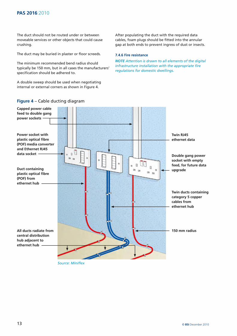
PAS 20162010
9 Documentation and handover
All outlets at the home distributor and throughout the dwelling should be clearly labelled in accordance with BS EN 50174-1
The labelling of outlet sockets face-plates will be unacceptable if located on the exposed face of the socket The label should be fixed within the faceplate back box The labelling should be firmly located to ensure it is not displaced when the faceplate is removed
The location dimensions andor capacity of pathways into which information technology cabling has been
installed should be recorded together with details of any mitigation measures applied to provide the required environment in accordance with BS EN 50174-1 These recordings should include the position of the CPE equipment within the primary distribution space
This documentation should be passed to the occupier of the property when they move into the dwelling
The documentation should include digital installation instructions and should be passed to subsequent occupiers
copy BSI December 2010 15
PAS 20162010
Bibliography
Standards publications
BS EN 61386ndash 1 Conduit systems for cable management ndash Part 1 General requirements
BS EN 61386ndash 21 Conduit systems for cable management ndash Particular requirements ndash Part 21 Rigid conduit systems
BS EN 61386ndash 22 Conduit systems for cable management ndash Particular requirements ndash Part 22 Pliable conduit systems
BS EN 61386ndash 23 Conduit systems for cable management ndash Particular requirements ndash Part 23 Flexible conduit systems
BS EN 61386ndash 24 Conduit systems for cable management ndash Particular requirements ndash Part 24 Conduit systems buried underground
Other publications
[1] Data Ducting Infrastructure for New Homes Guidance Note CLG March 2008
[2] Stephen Thorpe and Habinteg Housing Association Wheelchair housing design guide (2nd edition) BRE Press February 2006
Further reading
BS EN 50174-3 Information technology ndash Cabling installation ndash Part 3 Installation planning and practices outside buildings
BT Openreach ndash Buildersrsquo Guide to telecommunications infrastructure and installation May 2007
NICC Report April 2010 (full reference to be confirmed)
National Joint Utilities Group ndash Guidelines On The Positioning And Colour Coding Of Utilitiesrsquo Apparatus NJUG April 2003
copy BSI December 2010 16
PAS 20162010
BSI ndash British Standards Institution
BSI is the independent national body responsible for preparing British Standards
It presents the UK view on standards in Europe and at the international level
It is incorporated by Royal Charter
Revisions British Standards are updated by amendment or revision Users of British Standards should make sure that they possess the latest amendments or editions
It is the constant aim of BSI to improve the quality of our products and services We would be grateful if anyone finding an inaccuracy or ambiguity while using this Publicly Available Specification would inform the Information Centre
Tel +44 (0)20 8996 7111 Fax +44 (0)20 8996 7048 Email infobsigroupcom
BSI offers members an individual updating service called PLUS which ensures that subscribers automatically receive the latest editions of standards
Buying standards Orders for all BSI international and foreign standards publications should be addressed to Customer Services
Tel +44 (0)20 8996 9001 Fax +44 (0)20 8996 7001 Email ordersbsigroupcom
Standards are also available from the BSI website at wwwbsigroupcomshop
Information on standards BSI provides a wide range of information on national European and international standards through its Library Various BSI electronic information services are also available which give details on all its products and services Contact the Information Centre
Tel +44 (0)20 8996 7111 Fax +44 (0)20 8996 7048 Email infobsigroupcom
Subscribing members of BSI are kept up to date with standards developments and receive substantial discounts on the purchase price of standards For details of these and other benefits contact Membership Administration
Tel +44 (0)20 8996 7002 Fax +44 (0)20 8996 7047 Email membershipbsigroupcom
Information regarding online access to British Standards via British Standards Online can be found at wwwbsigroupcombsol
Further information about BSI is available on the BSI website at wwwbsigroupcom
Copyright Copyright subsists in all BSI publications BSI also holds the copyright in the UK of the publications of the international standardization bodies Except as permitted under the Copyright Designs and Patents Act 1988 no extract may be reproduced stored in a retrieval system or transmitted in any form or by any means ndash electronic photocopying recording or otherwise ndash without prior written permission from BSI
This does not preclude the free use in the course of implementing the standard of necessary details such as symbols and size type or grade designations If these details are to be used for any other purpose than implementation then the prior written permission of BSI must be obtained
Details and advice can be obtained from the Licensing Department
Tel +44 (0)20 8996 7070 Fax +44 (0)20 8996 7512 Email copyrightbsigroupcom
copy BSI December 2010 17
British Standards Institution 389 Chiswick High Road London W4 4AL United Kingdom
wwwbsigroupcom
ISBN 978shy0shy580shy67917shy9
9 780580 679179
PAS 20162010
Bibliography
Standards publications
BS EN 61386ndash 1 Conduit systems for cable management ndash Part 1 General requirements
BS EN 61386ndash 21 Conduit systems for cable management ndash Particular requirements ndash Part 21 Rigid conduit systems
BS EN 61386ndash 22 Conduit systems for cable management ndash Particular requirements ndash Part 22 Pliable conduit systems
BS EN 61386ndash 23 Conduit systems for cable management ndash Particular requirements ndash Part 23 Flexible conduit systems
BS EN 61386ndash 24 Conduit systems for cable management ndash Particular requirements ndash Part 24 Conduit systems buried underground
Other publications
[1] Data Ducting Infrastructure for New Homes Guidance Note CLG March 2008
[2] Stephen Thorpe and Habinteg Housing Association Wheelchair housing design guide (2nd edition) BRE Press February 2006
Further reading
BS EN 50174-3 Information technology ndash Cabling installation ndash Part 3 Installation planning and practices outside buildings
BT Openreach ndash Buildersrsquo Guide to telecommunications infrastructure and installation May 2007
NICC Report April 2010 (full reference to be confirmed)
National Joint Utilities Group ndash Guidelines On The Positioning And Colour Coding Of Utilitiesrsquo Apparatus NJUG April 2003
copy BSI December 2010 16
PAS 20162010
BSI ndash British Standards Institution
BSI is the independent national body responsible for preparing British Standards
It presents the UK view on standards in Europe and at the international level
It is incorporated by Royal Charter
Revisions British Standards are updated by amendment or revision Users of British Standards should make sure that they possess the latest amendments or editions
It is the constant aim of BSI to improve the quality of our products and services We would be grateful if anyone finding an inaccuracy or ambiguity while using this Publicly Available Specification would inform the Information Centre
Tel +44 (0)20 8996 7111 Fax +44 (0)20 8996 7048 Email infobsigroupcom
BSI offers members an individual updating service called PLUS which ensures that subscribers automatically receive the latest editions of standards
Buying standards Orders for all BSI international and foreign standards publications should be addressed to Customer Services
Tel +44 (0)20 8996 9001 Fax +44 (0)20 8996 7001 Email ordersbsigroupcom
Standards are also available from the BSI website at wwwbsigroupcomshop
Information on standards BSI provides a wide range of information on national European and international standards through its Library Various BSI electronic information services are also available which give details on all its products and services Contact the Information Centre
Tel +44 (0)20 8996 7111 Fax +44 (0)20 8996 7048 Email infobsigroupcom
Subscribing members of BSI are kept up to date with standards developments and receive substantial discounts on the purchase price of standards For details of these and other benefits contact Membership Administration
Tel +44 (0)20 8996 7002 Fax +44 (0)20 8996 7047 Email membershipbsigroupcom
Information regarding online access to British Standards via British Standards Online can be found at wwwbsigroupcombsol
Further information about BSI is available on the BSI website at wwwbsigroupcom
Copyright Copyright subsists in all BSI publications BSI also holds the copyright in the UK of the publications of the international standardization bodies Except as permitted under the Copyright Designs and Patents Act 1988 no extract may be reproduced stored in a retrieval system or transmitted in any form or by any means ndash electronic photocopying recording or otherwise ndash without prior written permission from BSI
This does not preclude the free use in the course of implementing the standard of necessary details such as symbols and size type or grade designations If these details are to be used for any other purpose than implementation then the prior written permission of BSI must be obtained
Details and advice can be obtained from the Licensing Department
Tel +44 (0)20 8996 7070 Fax +44 (0)20 8996 7512 Email copyrightbsigroupcom
copy BSI December 2010 17
British Standards Institution 389 Chiswick High Road London W4 4AL United Kingdom
wwwbsigroupcom
ISBN 978shy0shy580shy67917shy9
9 780580 679179

British Standards Institution 389 Chiswick High Road London W4 4AL United Kingdom
wwwbsigroupcom
ISBN 978shy0shy580shy67917shy9
9 780580 679179