parts & service manual - wesellit ltdwesellit.ca/m/files/dimplex30_parts_service.pdf · parts...
TRANSCRIPT

PARTS & SERVICE MANUAL FOR THE 30”
ELECTRIC FIREPLACE
MODEL NUMBER
DFB6016
1
TABLE OF CONTENTS OPERATION PAGE 2 PARTS DRAWING PAGE 4 PARTS LIST PAGE 5 WIRING DIAGRAM PAGE 6 LIGHT BULB REPLACEMENT PAGE 7 LED/SWITCH HARNESS REPLACEMENT PAGE 9 LIGHT DIMMER SWITCH REPLACEMENT PAGE 10 FLAME SPEED CONTROL REPLACEMENT PAGE 11 FLAME MOTOR/FLAME ROD REPLACEMENT PAGE 12 HEATER ON/OFF SWITCH REPLACEMENT PAGE 14 HEATER ASSEMBLY REPLACEMENT PAGE 15 CIRCUIT BOARD REPLACEMENT PAGE 17 POWER CORD REPLACEMENT PAGE 18

2
OPEN
EF3003, SF3003, DF3003 OPERATION Initializing The Remote Control 1. Turn on the electrical power at the circuit breaker. 2. Slide open the battery cover on the back of the remote transmitter. 3. Install one 9 volt battery into the remote control. Replace the battery cover.
.
Remote Control Operation
The fireplace is supplied with a radio frequency remote control. This remote control has
a range of approximately 50 feet. (15.25 m), it does not have to be pointed at the fireplace and can pass through most obstacles (including walls). It is supplied withone of 243 independent frequencies to prevent interference with other units. The frequency designation is indicated on the back of the transmitter.
Remote Control Initialization This procedure is required every time there is a loss of power to the remote control in
the fireplace. (ie. Power failure, breaker tripped, main power switch is turned off)
1. Ensure that the power is supplied through the main service panel. 2. Locate manual controls (refer to fig. 1) 3. Activate main power switch (“_” position) red indicator light 1will flash. 4. Press and hold manual selection switch for five seconds (“_” position) UNTIL the
second red indicator light flashes. 5. Press ON button located on the remote control transmitter (fig. 2). This will
synchronize the remote control transmitter and receiver.
The remote control operates the fireplace levels sequentially. The level is increased every time the ON button on the transmitter is pressed. The fireplace can be turned off at any point by pressing the OFF button on the remote control transmitter.

3
Electric Fireplace Manual Controls A. Manual on/off switch 1. The fireplace has a manual power ON/OFF switch located on the control panel of
the fireplace. 2. To operate press the switch once, to turn the unit on. Press the switch again to turn
the unit off. B. Flame brightness control Turn the flame brightness control knob to increase or decrease the brightness of the flame and embers. C. Flame action control Turn the flame action control knob to adjust the flame speed control to the desired level. D. Manual Selection Switch To choose between the flame effect setting, flame effect with low heat setting, and flame effect with high heat setting.
RESETTING THE TEMPERATURE CUTOFF SWITCH Should the heater overheat, an automatic cut out will turn the heater off and it will not come back on without being reset. It can be reset by switching the MAIN ON/OFF SWITCH to OFF and waiting 5 minutes before switching the unit back on. CAUTION If you need to continuously reset the heater, unplug the unit and call Dimplex North America Limited at 1-800-668-6663.

4
DFB6016
5
13
16
15
15
11
8
6
10
1
14
3
9
12
2
4

5
DFB6016
REPLACEMENT PARTS FIREBOX, 30” – Dimplex CATALOGUE NO. DFB6016 PART NO. 6901110559 REPLACEMENT PART 1. 30” LOG SET ASSEMBLY 0438550100RP 2. MOTOR, ASSEMBLY 1200W,980RPM 2200490200RP 3. WIRE ASSY LAMPHOLDER 4 SOCKET 2500190500RP 4. UPPER WIRE ASSY LAMPHOLDER 2 SOCKETS 4200090100RP 5. ON/OFF SWITCH 2800070200RP 6. REMOTE CONTROL RECEIVER 3 STAGE 3000430800RP 7. REMOTE CONTROL SENDER 3 STAGE (Not Shown) 3000370300RP 8. FLAME SPEED 3000240100RP 9. FLAME MOTOR 3000240200KIT 10. CONTROL, DIMMER 3000250100RP 11. CORD SET 4100040500RP 12. REFLECTOR ASSY 5900080700RP 13. MIRROR 5900300400RP 14. FRONT GLASS 5900310300RP 15. FLAT BLACK KNOB 8800000200RP 16. HEAT SWITCH 2800070500RP

6
WIRING DIAGRAM

7
DFB6016 If unit was operating prior to servicing allow at least 10 minutes for light bulbs and heating element to cool off to avoid accidental burning of skin. Disconnect power before attempting any maintenance or cleaning to reduce the risk of electric shock or damage to persons. Light bulbs need to be replaced when you notice a dark section of the flame. There are four bulbs under the log set which generate the flames and embers. It is a good idea to replace all of the light bulbs at one time if they are close to the end of their rated life. Group replacement will reduce the number of times you need to open the unit to replace the light bulbs.
LOWER BULB REPLACEMENT
1. Remove the trim by turning the retaining fasteners counter clockwise ¼ turn until the
trim releases from the firebox using a slotted screwdriver. (FIGURE 1) 2. Hold the glass in place while removing the retaining clip from the upper center of the
firebox. 3. Lift glass out and store in a safe place.
4. Lift up the front edge of the log until it clears the front tabs. Pull out until the rear tab clears the back ledge, then lift out.
5. Examine the bulbs to determine which bulbs require replacement. 6. Hold the socket while unscrewing the bulb. 7. Hold the socket while screwing in the new bulb. 8. Replace the log emberbed by placing the back lip of the log emberbed under the
mirror then push the front of the log emberbed down into the recess.
LOWER LIGHT BULB REQUIREMENTS Quantity of 4 clear chandelier or candelabra bulbs with an E-12 (small) socket base, 60 watt rating.
FIGURE 1
8
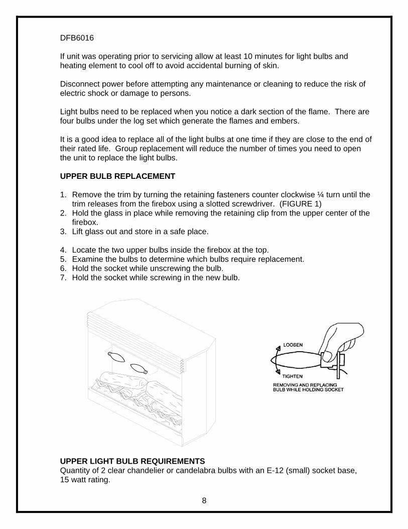
DFB6016 If unit was operating prior to servicing allow at least 10 minutes for light bulbs and heating element to cool off to avoid accidental burning of skin. Disconnect power before attempting any maintenance or cleaning to reduce the risk of electric shock or damage to persons. Light bulbs need to be replaced when you notice a dark section of the flame. There are four bulbs under the log set which generate the flames and embers. It is a good idea to replace all of the light bulbs at one time if they are close to the end of their rated life. Group replacement will reduce the number of times you need to open the unit to replace the light bulbs.
UPPER BULB REPLACEMENT
1. Remove the trim by turning the retaining fasteners counter clockwise ¼ turn until the
trim releases from the firebox using a slotted screwdriver. (FIGURE 1) 2. Hold the glass in place while removing the retaining clip from the upper center of the
firebox. 3. Lift glass out and store in a safe place.
4. Locate the two upper bulbs inside the firebox at the top. 5. Examine the bulbs to determine which bulbs require replacement. 6. Hold the socket while unscrewing the bulb. 7. Hold the socket while screwing in the new bulb.
UPPER LIGHT BULB REQUIREMENTS Quantity of 2 clear chandelier or candelabra bulbs with an E-12 (small) socket base, 15 watt rating.

9
DFB6016 If unit was operating prior to servicing allow at least 10 minutes for light bulbs and heating element to cool off to avoid accidental burning of skin. Disconnect power before attempting any maintenance or cleaning to reduce the risk of electric shock or damage to persons. TO REPLACE LED/SWITCH HARNESS 1. Remove the trim by turning the retaining fasteners counter clockwise ¼ turn until the
trim releases from the firebox using a slotted screwdriver.
2. Remove the firebox from mantel. 3. Lower the grill covering the controls. 4. Remove the (10) retaining screws on the top cover and remove the top being careful
not to damage any of the wiring. 5. Locate the main on/off switch mounted on the top panel and disconnect the wiring
clips and connections noting their original locations. 6. Depress the retainer clips on the rear of the switch and push the switch out of the
rear of the cover.

10
DFB6016 If unit was operating prior to servicing allow at least 10 minutes for light bulbs and heating element to cool off to avoid accidental burning of skin. Disconnect power before attempting any maintenance or cleaning to reduce the risk of electric shock or damage to persons. TO REPLACE LIGHT DIMMER SWITCH 1. Remove the trim by turning the retaining fasteners counter clockwise ¼ turn until the
trim releases from the firebox using a slotted screwdriver.
2. Remove the firebox from the mantel. 3. Lower the grill covering the controls. 4. Remove the (10) retaining screws on the top panel and remove the top being careful
not to damage any of the wiring.
5. Pull off the control knob from the dimmer control and remove the mounting nut.
6. Locate the light dimmer control mounted on the top panel and disconnect the wiring clips and connections noting their original locations.
7. From under the top panel, break off the four mounting studs on the light dimmer
control by grasping with pliers and twisting on the protruding part of the stud, push the remainder of the studs out through the top panel. NOTE: New mounting studs are supplied with the replacement light dimmer.
8. Properly orientate the new light dimmer control and connect all of the wiring connections.
9. Reassemble in the reverse order as above.
11
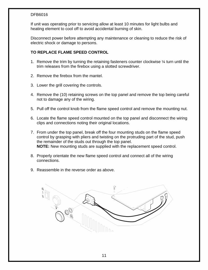
DFB6016 If unit was operating prior to servicing allow at least 10 minutes for light bulbs and heating element to cool off to avoid accidental burning of skin. Disconnect power before attempting any maintenance or cleaning to reduce the risk of electric shock or damage to persons. TO REPLACE FLAME SPEED CONTROL 1. Remove the trim by turning the retaining fasteners counter clockwise ¼ turn until the
trim releases from the firebox using a slotted screwdriver.
2. Remove the firebox from the mantel.
3. Lower the grill covering the controls.
4. Remove the (10) retaining screws on the top panel and remove the top being careful not to damage any of the wiring.
5. Pull off the control knob from the flame speed control and remove the mounting nut.
6. Locate the flame speed control mounted on the top panel and disconnect the wiring
clips and connections noting their original locations.
7. From under the top panel, break off the four mounting studs on the flame speed control by grasping with pliers and twisting on the protruding part of the stud, push the remainder of the studs out through the top panel. NOTE: New mounting studs are supplied with the replacement speed control.
8. Properly orientate the new flame speed control and connect all of the wiring
connections.
9. Reassemble in the reverse order as above.

12
DFB6016 If unit was operating prior to servicing allow at least 10 minutes for light bulbs and heating element to cool off to avoid accidental burning of skin. Disconnect power before attempting any maintenance or cleaning to reduce the risk of electric shock or damage to persons.
TO REPLACE FLAME MOTOR/FLAME ROD 1. Remove the trim by turning the retaining fasteners counter clockwise ¼ turn until the
trim releases from the firebox using a slotted screwdriver.
2. Remove the firebox from the mantel.
3. Remove front glass retaining clip, while holding the front glass.
4. Remove the front glass and set aside.
5. Remove the log set by lifting up the front edge of the log until it clears the front tabs. Pull out until the rear tab clears the back ledge, then lift out.
6. Cut the flicker motor wires close to the flicker motor end with wire cutters. 7. Remove the reflector rod from the flicker motor by pulling the end of the rod to the
left and cut the reflector spring with wire cutters. DO NOT TAKE THE LEFTOVER SPRING OFF THE END OF THE REFLECTOR ROD
8. Remove the (2) screws securing the flicker motor to the flicker motor bracket.
9. Discard the old flicker motor.
10. Pick up the 1 ½” rubber sleeve and locate over remaining spring on reflector rod.
ENSURE TO LOCATE THE LARGE OPENING OF THE RUBBER SLEEVE OVER THE REMAINING SPRING OF THE REFLECTOR ROD.
11. Pick up new flicker motor and cut wire leads to 3 ½” long with wire cutters.
12. Secure new flicker motor to the existing reflector rod. Ensure the flicker motor
bracket is in between the motor and the reflector rod.
13. Pick up slip joint pliers and adjust to proper slot.
14. Pick up wire connector and place (1) yellow wire into each terminal. (total of 2
yellow wires) 15. Secure wire connector by crimping the 3M symbol with slip joint pliers. 16. Pull on end of wires to ensure a strong connection.

13
17. Repeat this process for the (4) remaining wires. (red, blue, orange, grey) 18. Reassemble in the reverse order.

14
DFB6016 If unit was operating prior to servicing allow at least 10 minutes for light bulbs and heating element to cool off to avoid accidental burning of skin. Disconnect power before attempting any maintenance or cleaning to reduce the risk of electric shock or damage to persons. TO REPLACE HEATER ON/OFF SWITCH 1. Remove the trim by turning the retaining fasteners counter clockwise ¼ turn until the
trim releases from the firebox using a slotted screwdriver.
2. Remove the firebox from the mantel. 3. Lower the grill covering the controls.
4. Remove the (10) retaining screws on the top panel and remove the top being careful
not to damage any of the wiring.
5. Locate the heater on/off switch mounted to the top panel and disconnect the wiring clips and connections noting their original locations.
6. Depress the retainer clips on the rear of the switch and push the switch out of the
rear cover.
7. Properly orientate the new switch and connect all of the wiring clips and connections.
8. Reassemble in the reverse order as above

15
DFB6016 If unit was operating prior to servicing allow at least 10 minutes for light bulbs and heating element to cool off to avoid accidental burning of skin. Disconnect power before attempting any maintenance or cleaning to reduce the risk of electric shock or damage to persons. TO REPLACE HEATER ASSEMBLY
1. Remove the trim by turning the retaining fasteners counter clockwise ¼ turn until the trim releases from the firebox using a slotted screwdriver.
2. Remove the firebox from the mantel.
3. Lower the grill covering the controls.
4. Remove the (10) retaining screws on the top panel and remove the top being careful not
to damage any of the wiring.
5. Hold the glass in place while removing the retaining clip from the upper center of the firebox.
6. Lift glass out and store in a safe place.
7. Locate the two upper bulbs inside the firebox at the top.

16
8. Hold the light sockets while unscrewing the bulbs.
9. Remove the yellow wire from the heater element coming from the heater on/off switch.
10. Remove the blue wire from the circuit board coming from the temperature cutoff switch.
11. Remove the (2) element mounting screws from the top of the element located on both
sides of the temperature cutoff switch.
12. Remove the (4) heater assembly mounting screws from inside the firebox and set aside the heater assembly.
13. Disconnect wiring connections and connect to replacement heater assembly noting their
original locations.
14. Reassemble in the reverse order as above.

17
DFB6016 If unit was operating prior to servicing allow at least 10 minutes for light bulbs and heating element to cool off to avoid accidental burning of skin. Disconnect power before attempting any maintenance or cleaning to reduce the risk of electric shock or damage to persons. TO REPLACE THE CIRCUIT BOARD 1. Remove the trim by turning the retaining fasteners counter clockwise ¼ turn until the
trim releases from the firebox using a slotted screwdriver.
2. Remove the firebox from the mantel.
3. Lower the grill covering the controls.
4. Remove the (10) retaining screws on the top panel and remove the top being careful not to damage any of the wiring.
5. Remove wiring connections from circuit board noting their original locations.
6. From under the top panel, break off the six mounting studs on the flame speed
control by grasping with pliers and twisting on the protruding part of the stud, push the remainder of the studs out through the top panel. NOTE: New mounting studs are supplied with the replacement speed control.
7. Properly orientate the new circuit board and connect all of the wiring connections.
8. Reassemble in the reverse order as above.

18
DFB6016 If unit was operating prior to servicing allow at least 10 minutes for light bulbs and heating element to cool off to avoid accidental burning of skin. Disconnect power before attempting any maintenance or cleaning to reduce the risk of electric shock or damage to persons. TO REPLACE THE POWER CORD 1. Remove the trim by turning the retaining fasteners counter clockwise ¼ turn until the
trim releases from the firebox using a slotted screwdriver.
2. Remove the firebox from the mantel.
3. Lower the grill covering the controls. 4. Remove the (10) retaining screws on the top panel and remove the top being careful
not to damage any of the wiring.
5. Located and disconnect the power cord wiring connections from the circuit board noting their original locations.
6. With needle nose pliers grasp the power cord strain relief grommet from inside the
rear panel and push while twisting to remove.
7. Pull the power cord out through the hole in the rear cover.
8. Install the new cord set through the hole in the rear cover by placing the strain relief over the cord, hold the strain relief with pliers and slide into mounting hole.
9. Connect all of the wiring connections in their original locations on the circuit board.
10. Reassemble in the reverse order as above.