parts & service manual - simeri oy henkilönostin palvelut tl49j.pdf · parts & service...
TRANSCRIPT

PARTS & SERVICE
MANUALPart Number: 513868-200
March 2013
Serial Number TL49-01-008562 and after.


TL49JENGLISHWhen contacting Snorkel for service or parts information, be sure to include the MODEL and SERIAL NUMBERS from the equipment nameplate. Should the nameplate be missing, the SERIAL NUMBER is also stamped on top of the chassis bhind the toe hitch.
MANUFACTURER
VIN
TYPE APPROVAL
MAX GROSS WT
MAX AXLE WT
TYPE
VARIANT
SER NR
YEARPART No: 508945-004
Kg
Kg
Kg
0 -
1 -
SNORKEL IS A TRADING DIVISION OF:
TANFIELD POWERED ACCESS LTD.VIGO CENTRE, BIRTLEY ROAD,
WASHINGTON,TYNE & WEAR, U.K.
T: +44 (0)845 1550 057
TANFIELD POWERED ACCESS LTD.
e11*2007/46*0879
SERIALNUMBER
MODELNUMBER
NON-LOADEDMACHINEWEIGHT
lbskg MAXIMUM
WHEELLOAD
lbskgENGINE
POWEREDMODELS
hpkW BATTERY
POWEREDMODELS
VDRIVEMOTORS
BATTERIESVAh
MONTH / YEAROF MANUFACTURE
MAXIMUMPLATFORMHEIGHT
RATED NUMBEROF OCCUPANTS
ftm MAXIMUM
DRIVEHEIGHT
ftm
MAXIMUMPLATFORMLOAD
MAXIMUMALLOWABLEWIND SPEED
mphm/s
MAXIMUMPLATFORMREACH
ftm
511039-300
MAXIMUMALLOWABLEMANUAL FORCE(SIDE PULL)
lbsN
Indoors Outdoors
SLOPE SENSOR ALARM SETTINGFRONTTO BACK deg SIDE
TO SIDE deg
MAXIMUMOUTRIGGERLOAD
lbskg
MAXIMUMGRADEABILITY %
CHARGERINPUT V
ASSEMBLED IN
Axle weights with machine in the stowed position.
lbslbs
kgkg
DRIVE AXLESTEER AXLE
Snorkel,Vigo Centre, Birtley Road,Washington, Tyne & Wear,NE38 9DA, U.K.
Indoors Outdoors
CAUTIONONLY trained and authorised personnel may operate this machine.Consult the Operation Manual before using this machine.
DO NOT make any changes to this machine, any changes made will invalidate the manufactures warranty and may contravene legislation.
200kg = 2 Persons + 40kg Tools
TL49J BI ENERGY
-------------2300
-------------N/A
N/A
-------------1320
-------400
-------400
-------------15.0
2 2
-------------N/A
N/A N/A
N/A
31024
-------------12.5
-------------9.10
-------------N/A
110/220
1002200
--------------------------
Serial number stamped on chassis behind the �������������� ������������������������
Number Plate.
www.snorkellifts.com

Harness attachment points are provided in the platform and the manufacturer recommends the usage of a fall restraint harness, especially where required by national safety regulations.All harness attachment points on SNORKEL vehicles have been tested with a force of 3,650 lbs (16.3 KN)per person.See below examples of harness attachment points used on SNORKEL vehicles with their corrosponding rating;
Type 1.
Harness attachment point Type 1. is rated for one lanyard attachment per loop as shown in the illustrations depending upon platform occupancy rating (see operators manual & decals).
Type 2.
Harness attachment point Type 2. is rated for two lanyard attachments per loop as shown in the illustrations depending upon platform occupancy rating (see operators manual & decals).
Type 3.
Harness attachment point Type 3. is rated for one lanyard attachment per loop as shown in the illustrations depending upon platform occupancy rating (see operators manual & decals).
Top View Top View
2 lanyard attachments
Top View
1 lanyard attachment
Top View
2 lanyard attachments
1 lanyard attachment
1 lanyard attachment
Top View
Front View
Type 4.
Harness attachment point Type 4. is rated for one lanyard attachment per loop as shown in the illustrations depending upon platform occupancy rating (see operators manual & decals).
1 lanyard attachment
NOTE: There can be more harness attachment points per machine than the maximum number of occupants allowed in a platform. Refer to the platform decal & specifications table listed in the operators
manual for the correct occupancy rating before use.
SAFETY NOTICE

TL49J513868-000
OPERATORS MANUALSafety Rules
All personnel shall carefully read, understand and follow all safety rules and operating instructions before operating or performing maintenance on any SNORKEL aerial work platform
Electrocution Hazard Tip Over Hazard Collision Hazard Fall Hazard
This Machine is NOT Insulated
NEVER elevate the platform or drive the machine while elevated unless the machine is
on a firm, level surface.
NEVER position the platform without first checking for overhead obstructions
or other hazards.
NEVER climb, stand, or sit on platform guardrails or midrail.
USE OF THE AERIAL WORK PLATFORM: This aerial work platform is intended to lift persons and his tools as well as the material used for the job. It is designed for repair and assembly jobs and assignments at overhead workplaces (ceilings, cranes, roof structures, buildings etc.). All other uses of the aerial work platform are prohibited!
THIS AERIAL WORK PLATFORM IS NOT INSULATED! For this reason it is imperative to keep a safe distance from live parts of electrical equipment!
����������������������������������������������is prohibited! See “Special Limitations” for details.
The use and operation of the aerial work platform as a lifting tool or a crane (lifting of loads from below upwards or from up high on down) is prohibited!NEVER exceed the manual force allowed for this machine. See “Special Limitations” for details.
DISTRIBUTE all platform loads evenly on the platform.
NEVER���������������������������������� ����������������������������������������������������"������bumps, curbs, or debris; and avoiding them.
OPERATE machine only on surfaces capable of supporting wheel loads.
NEVER operate the machine when wind speeds exceed this machine’s wind rating. See “Beaufort Scale” for details.
IN CASE OF EMERGENCY push EMERGENCY STOP switch to deactivate all powered functions.
IF ALARM SOUNDS��������������������� �����#$%'������������������������*�/� ������������������� ���surface.
Climbing up the railing of the platform, standing on or stepping from the platform onto buildings, steel or prefab concrete structures, etc., is prohibited!Dismantling the swing gate or other railing components is prohibited! Always make certain that the swing gate is closed and securely locked!
It is prohibited�������������������������������������3�����������������"�����6�������������������������<�
To extend the height or the range by placing of ladders, scaffolds or similar devices on the platform is prohibited!NEVER perform service on machine while platform is elevated without blocking elevating assembly.
INSPECT the machine thoroughly for cracked welds, loose or missing hardware, hydraulic leaks, loose wire connections, and damaged cables or hoses before using.
VERIFY that all labels are in place and legible before using.
NEVER use a machine that is damaged, not functioning properly, or has damaged or missing labels.
To bypass any safety equipment is prohibited and presents a danger for the persons on the aerial work platform and in its working range.
NEVER��������������������������������=��*�>��������������������������� ������������*�
/�����������������������������������are prohibited or permissible only at the approval by SNORKEL.
AFTER USE, secure the work platform from unauthorized use by turning both keyswitches off and removing key.

2 TL49J513868-000
CONTENTS
Page Introduction 3Description of Equipment 4������������� ������ �Working Envelope 6Operator Requirements 7Warning Notices 8 . Beaufort Scale 9Towing Instructions 10Hand Manoeuvring (Friction Drive Option) 12 Pre-Start Checks 13Power Supply 19Batteries, & Power Pack 15Setting Up 16Extending Structure 18 . Basket Controls 18 . Ground Controls 20Safety Harness 21Emergency Controls . Emergency Stops 21 . Emergency Lower (Electronically) 22 . Emergency Lower (Manually) 23 . Emergency Raise Outriggers 24 . Emergency Cage Overload 24 . Emergency Battery Isolation 25Stowing the Machine 26
Maintenance . Daily Checks 27 . Weekly and Monthly Checks 28 . Slew Drive and Limit Switches 29 . Trailer Lighting Diagram 30Appendices Petrol/Bi-fuel Option. 31 Generator Option. 32 Mains connection. 33

3TL49J 513868-000
The SNORKEL TL49J is a class leader, offering several features as standard that other manufacturers only provide as optional extras.
These include powered basket rotation and fully proportional hydraulic controls, at both basket and ground level.
$���������=���������������?@J�Q�XZ��#�������������������������������������������������������������������[J�Q�XZ��#����������������� �����������������������������������vital for working in tight spaces.
SNORKEL Powered Access has a global reputation for innovation and a proud heritage in the design and manufacture of high quality powered access equipment.
The company was founded in the US more than 65 years ago, on the principle of constantly improving service excellence for end users. Every model in our growing range of versatile, trailer mounted units is a class leader and together they have set new industry benchmarks.
%��� ���������� ��� �������� �� ������� ����� ]^J�JJJ�_� ��� ��� ���� ����� ���������� ������and support capacity, mean SNORKEL can offer complete solutions to meet even the most demanding access applications.
#`%Z{�|�����������������������������_�������������#%�[JJ?�����������������������the CE mark, complying with or exceeding all relevant standards and EC directives.
SNORKEL Powered Access is a member of the International Powered Access Federation (IPAF).
To ensure you are fully aware of safety and operational information, the following symbols are used throughout this manual;
This type of box contains, Points of operation to NOTE.
! The information contained in this type of box contains, WARNING text. It gives Warnings about the risk of Damage to equipment, and possibly personnel.
The information contained in this type of box contains, DANGER text. It gives Warnings about the risk of PERSONAL INJURY to the opera-tor and or others.
INTRODUCTION

4 TL49J513868-000
The SNORKEL TL49J is of the parallel linkage vertical boom design, mounted on a road �������������*�$�����_�������� ���������������������������� ����������������������control ability combined with a robust construction to withstand a heavy working environment
The TL49J machine is designed for two man capacity (200 kg S.W.L.).
$�����������������������������������������"������������ ����������������������������������������������*�$���$|~[���������������������������������������=���"����boom and rotating cage for extra manoeuvrability.
The hydraulic system is of a failsafe design throughout, with built in hydraulic lock valves on all of the rams as a precaution against hose failure. The machine is controlled by means of proportional manual controls of the ‘direct hand’ lever operating type. These valves are located at both the base and in the cage, as standard.
������������������������������������� � �����������������������������������������be lowered from the base and basket.
$��������������������������������������������������������������������������� �������������from being raised without the outriggers being extended and under load. An interlock prevents the hydraulic outriggers being accidentally retracted while the booms are raised. A simple system of warning lights show the power supply is on and each of the outriggers is under load.
Performance.
/��������������������� ?�*JJ���/�������������%��������� [*?J���>������3]���������6��� ]JJ����#������������ ��J����������`��������������3������6��� �J���3�6�
Construction Standards.
The machine complies fully with the requirements of the following EEC Directives: Q������ ��[��@���>��������/�������Q������ ��*Q������ ���[�@@����>����������������������>������������Q������ ��*Q������ ���@�]@���>��������|����������Q������ ��*�
�`��J]J"?�?[[@��#��������/������*��
The machine is designed and tested in accordance with all relevant B.S.I and European Standards including EN280.
DESCRIPTION OF EQUIPMENT

5TL49J 513868-000
Cage Dimensions |������ ?*]J��������� J*�J��X���"������������ ?*?J��$��"������������� J*?^��
Operating Dimensions /��������������������� ?�*JJ��/������>����������� ?^*JJ��/������%�������3����������������������6�� [*?J��
Travel Dimensions $�����|������ � �*?J��>������������� � ?*�^�>�������������� � ]*?J��������� 3�������/����6�� ]]^J����3�"���6�� 3�������/���������������Q�� �6�� ]@[^����3�"���6�� 3��"�����/����6�� ]@JJ����3�"���6��
Operating Parameters #����������|���� ]JJ����/���������������'����� ~JJ`�/����������#������ ?]*^���"?
Z������� ��J�>���#����� [J��
Equipment Bottom Ram Double acting: Bore ��J*J����� � Z�����^J*J����
$���Z�� Q������������ ��������J*J����� � Z�����^J*J����
$�����Z��� Q������������� ��������^*J������ � Z�����~^*J����
������Z��� Q������������� ��������J*J������ � Z�����~J*J����
#���������Z��� Q������������� ��������J*J������ � Z�����~J*J����
Bottom & Top Ram Lock Valves Pilot operated over centre valves
Control Valve (Cage) Monoblock unit consisting of seven double acting spools
>�������� ��3X����6�� /������������������������� �������� acting spools
Control Valve (Stabiliser) Monoblock unit consisting of four double acting spools
Bushes Acetol resin polymer with sintered bronze base (DX)
Pivot Pins Stainless Steel Bright Bar � $��X�����#[�J�@J@�#@?�>����� � /�����?~����$��������$��"��?������*�
TECHNICAL SPECIFICATION

6 TL49J513868-000
Height and Distance in Metres.
OPERATING ENVELOPE
]JJ��Unrestricted SWL

7TL49J 513868-000
Please read this carefully, and ensure you have received the correct training prior to operating this machine.
1.�� $���������������������������������������������� ������������������������������hearing.
2. You must have a good head for heights.
3. Your primary concern must be the safe operation of the work platform, the safety of the people working with you, and the safety of other persons in your working area.
4. You must be familiar with the contents of this manual, and at no time attempt to operate the machine beyond the recommended limits.
5. The proper care of the work platform is a major factor in ensuring the safety of those who work with it.
6. You must not misuse the machine or ignore or interfere with the devices that have been provided to maintain safety.
7. Operation of the machine should be restricted to personnel who have been authorised to operate the equipment and have received proper training.
OPERATOR REQUIREMENTS

8 TL49J513868-000
1. DO NOT operate this machine unless you have been fully trained in its safe use.
2. DO NOT operate the machine on soft, slippery or sloping ground unless adequate precautions have been taken.
� $������������������������� ���������������� �� ���������������������������������������^J`���2.
� $���������������������������������������?]*^�`*�
Advice should be obtained from SNORKEL as to the type of supports and precautions required before attempting to operate the machine outside these parameters.
3. DO NOT use any equipment in the basket to increase the reach or working height of the machine, e.g. ladders.
4. DO NOT���������������_����������������������������������������������������e.g. notice boards.
5. DO NOT use the machine for any application that may produce special loads or forces: the manufacturer, SNORKEL Powered Access, must be consulted for approval of special applications prior to use.
6. DO NOT use the machine close to live electrical conductors. The minimum safe working distance for a machine working near overhead power cables is the maximum extended ������������������������?^��������������������������������������������������������i.e. safe working distance for the TL49J is 24 metres. It is the operator‘s responsibility to ���������������������������� ������������ ��� ����������" �����������������������safe working distance is maintained. Erect a simple barrier tape at the safe distance.
WARNING NOTICES
15m
26m
15m
24m
7. WORKING CLOSE TO POWER CABLES���������������������������������������������safe working distance, the operator must ensure that the electricity supply has been switched off. Before commencing work, a written permit to work must be obtained from the owners of the power cables or the responsible authority.
?^�
24m

9TL49J 513868-000
8. DO NOT operate the machine unless all four outriggers are down and in full contact with the ground. The machine must be level and the wheels lifted visibly clear of the surface before the booms are raised.
9. DO NOT move the machine with the basket raised and never allow cage or booms to slew into the path of oncoming vehicles.
10. DO NOT�������������������������������������������?]*^����*�����������������working near high buildings or structures, shielding and funnelling effects may cause high wind forces on days when the nominal wind speed in the open is low. Wind speed can either be measured from the work platform with a hand held anemometer or estimated using the Beaufort Scale.
BEAUFORT WIND SPEED SCALE
The Beaufort Scale of wind force is accepted internationally and is used in communicating ������� ��������*� ��� �������� ��� ������� J� "� ?]�� ���� ����������� � ������ �������� ��� �����������������?J��3@@��*6��� �����������������*�
Approximate corrections for wind speeds at other heights are:
� ]����������@J�� � @����������]J��� � �����������?J�� � ?^�����?J��� � @J�����]^��
Beaufort Scale
M/Sec Ground Conditions
@ @*^"^ ���������������� ����������������������� ��������������������
4 �"� Raises dust and loose paper; small branches are moved
5 ["?J Small trees in leaf begin to sway; crested wavelets on inland waterways�
6 ??"?@ �������������������������������������� �������������
� ?~"?� Whole trees in motion; inconvenience felt when walking against wind�
8 ?�"]? �������� ����������������������������������������
9 ]]"]~ Slight structural damage occurs (chimney pots and slates removed)
WARNING NOTICES

10 TL49J513868-000
������������������������ ����������������������� �������������� �����behind a car or van at speeds of up 50mph (80km/h) where permitted.
1. Before towing, check the capacity of the vehicle being used. (Machine weight will increase ������������������������6�
2. Ensure that the road tyres and brakes are in good, serviceable condition.
3.�� ������������������������������������������������������������������������������loops and secured with the “R” clip on the end of the chain.
TOWING INSTRUCTIONS

11TL49J 513868-000
4. Ensure that all outriggers are fully raised.
5. Use the Jockey Wheel to raise or lower the tow bar coupling to position the machine �� ������^J������������������������� ������*�
6. Apply the handbrake.
7. Lower the tow bar coupling down onto the ball hitch using the Jockey Wheel
8.�� #�����������������������3�������������������������^J������6*�
9. Fully raise the Jockey Wheel and lock in position.
10. Release the Handbrake.
11.�� '������������������������3���������6������������������ ������������������������������correctly.
TOWING INSTRUCTIONS
6 7
8 11 9

12 TL49J513868-000
1. Ensure that the booms are fully lowered, all outriggers are fully raised and the machine is in a menoeverable condition.
2. Engage the the friction drive cylinders against the trailer tyres by pulling actuating levers forward and down until they lock overcentre.
3. Ensure the power selector switch is set to Base.
4. Disengage the handbrake, and ensure that the Jockey wheel directional locking pin is removed
5. Traction is controlled via the 2 hydraulic levers on the R/H side of the chassis.
6. The left lever controls the left motor and the right lever the right.
Operating only the left lever forward will turn the machine right and the right lever will turn the machine left, operate both levers together for parallel drive.
7. When the machine is in position replace handbrake.
! Ensure friction drive cylinders are disengaged prior to platform operation or towing.
HAND MANOEUVERING (Optional)

13TL49J 513868-000
The following Pre-Start Checks should be carried out before taking the machine to the place of work.
1. Damaged or Loose Fittings. Visually Inspect the machine for signs of wear and tear, damage, loose or missing parts.
2. Wheels. (For towing only) � >��������������������������������������$|~[����������3^*]^���6*�
�� ������������� The hydraulic oil tank is located underneath the slew cover on the right hand side of the
machine (looking from the cage end), Ref, Fig.2, section J With the booms and outriggers in the transport position, the hydraulic oil level should be visible between the upper and lower marks of the Sight Glass.
Top up with ISO Grade 22 hydraulic oil if necessary.
�������������� ������
Serious injury or even death may result by not carrying out the following checks of the interlock system before the platform is used!
4. Safety Switches. Visually check the cage overload switch is free from damage.
Check all limit switch arms are free from damage and move easily (outrigger switches shown in Fig.6 ).
With outriggers in transport position, it must not be possible to operate the extending structure. With outriggers deployed, under load and top or bottom boom raised ������������^J����������������������������������������������������������*�
� ������������������������������ �� ��������.
PRE-START CHECKS

14 TL49J513868-000
5. Emergency Stop Switches. Emergency stop switches must operate correctly. Check that each stops the machine’s
controls and that restarting is prevented until all stop switches are unlatched.
6. Emergency Lower/Slew. � ����������������������������������������������^JJ��������������������������
off, check: The emergency lower switch located in the basket and ground control stations, lowers
the booms when operated. The emergency slew, telescopic boom retraction can be operated by using the hand
pump and control lever at the ground control station.
To Reset the hydraulic system after checks;
� !�������� ������������������������"�������������������������������� � !���������������#���������� �����������������������������$����������������%� � '�����������������������"�������������*��"����������*���������������� � !���������������!�����#��������
All rams must be fully extended at the same time before returning them to their transit ����������
If the Emergency Lower is used during normal operation, DO NOT use the machine, Contact your local SNORKEL representative.
7. Emergency Hand Pump. With the unit set up for working (i.e. outriggers down, under load and the machine level
with wheels clear of ground) it is possible to lower the cage using the emergency hand pump.
8. Battery Power (Where applicable) � >����������������� ������ ��������� ������������������������������ 3��������� ������
under the slew cover on both sides of the platform).� ���������������������������?]�J"?@]J��* With machine level, the distilled water should cover the plates by approximately 6mm.
9. Mains Power (Where applicable) Check that the voltage and frequency of the power input matches that of the motor.
��������������������������������]*^������������������?J������������������voltage drop.
10. Petrol/diesel Power (Where applicable) � >��������������������������������������������������������������������*�
PRE-START CHECKS

15TL49J 513868-000
Battery Power, 24V DC.
Ensure batteries have been fully charged before use and that the Battery Isolating Plug is securely connected.
Mains Power, (OPTIONAL)
>����� ���� ���� �������� ������� ??J�� ��� ]]J�]~J�� �*>*�� �������� ���� ���� ����������������*�>���������������������������������������������������ON position.
All extensions must be a minimum of 2.5mm2, and no longer than 10m, due to possible voltage drop, which will damage the motor. !
Petrol/diesel Power, (OPTIONAL)
Check the fuel and oil levels of the engine. Switch on the ignition using the key switch on the slew mounted legend panel. Check the engine runs using the start and stop buttons in the basket.
BATTERIES & POWER PACK
fig 1.
Batteries
fig 2.
Oil Filler & Sight glass
Hand Pump
Pump Handle
Power Pack

16 TL49J513868-000
1. Park the unit in an appropriate location at the workplace.
Do not attempt to set up the machine on steep slopes, ramps or soft ground.
2. Apply the handbrake on the trailer and remove from the towing vehicle.
3. With platform key switch set to ’Ground’ (Fig 3)
lower the outriggers by keeping the ‘Outrigger Motor Run’ button (Fig 4) pushed in, operate the appropriate ‘Outrigger control lever’ (Fig 5), until all four are 25mm to 50mm from the ground.
SETTING UP
fig 3.
GroundPlatform
fig 5.
Ground controlLevers.
Outrigger controlLevers.
Level Indicator
fig 4.
Motor Run (outrigger)
Motor Run (Booms)
EmergencyLower
Fig. 4

17TL49J 513868-000
4.�� |���������%���������������������������������������������3`����@�~6�����������ockey wheel just clears the ground.
^*�� |�����%����������?�]���������������|�Q������������������������������������*�3���shown below)
SETTING UP
! Take EXTREME care NOT to ground either the Basket, or the Jockey Wheel during the next step.
�*�� Z������������_���������%����������@�~*�
�*�� ����������������?�]����@�~������������������������������%�����������������������Outriggers are fully deployed, and the wheels are well clear of the ground.
8. Now, by using the Level indicator (Fig.5), raise opposite Outriggers until the bubble and indicator ring are concentric (i.e., the bubble rests in the centre).
9. Check that each LED on the Ground Control panel is still illuminated. This indicates that �������������������������������������������������*
The unit is designed to operate on a supporting surface of minimum bearing strength of 50N/cm2.
The maximum outrigger load is 12.5kN.

18 TL49J513868-000
?*�� Z��� �����������������������$�����'��������������������������|����������*
EXTENDING STRUCTURE
2. At the Ground Control Station, turn the key to ‘Basket’*�3#������*�@6�
@*�� >����� ���� ���� �����*� >����� ����all Emergency Stop Switches are released (twist release). The platform may now be raised, lowered or slewed in any direction by operating the control levers at the basket, whilst depressing the motor run button (DEADMAN).
fig 6.
Outrigger Ram
Limit Switch
Before raising, ensure there are no overhead obstructions or power �������������������������������������������������������
!*����+-*/+0+������ ������� �������������������������"������ ��������

19TL49J 513868-000
4. Explanation of the Basket Control Station, Directional Control Levers.
Outrigger LoadIndicators
EmergencyStop
Platform Overload Indicator
EmergencyLower
Motor Run(Booms)
Motor Run(Outrigger)
ControlSelector
fig 4a.
EXTENDING STRUCTURE
Cage Rotate
Cage Trim
Boom 3 Boom 2Telescope
Boom 2
Boom 1
Slewing
RaisePlatform
Trim
Lower Platform
Trim
SlewPlatform
Anticlockwise
SlewPlatform clockwise
RaiseJib
Boom
LowerJib
Boom
RetractTele-
Boom
ExtendTele-
Boom
RaiseTele-
Boom
LowerTele-
Boom
SlewTurret
Anticlockwise
SlewTurret
clockwise
RaiseBottomBoom
LowerBottomBoom

20 TL49J513868-000
Cage Rotate
Boom 3 Boom 2Telescope
Boom 2
Boom 1
Slewing
5. A duplicate set of controls (excluding Slew Basket) is mounted on the Slew Turret under the right hand side cover, which allows the platform to be operated from the Ground.
6. At the Ground Control Station, turn the key to ‘Ground’*�3#������*@6�
7. Explanation of the Ground Control Station, Directional Control Levers
EXTENDING STRUCTURE
SlewPlatform
Anticlockwise
SlewPlatform clockwise
RaiseJib
Boom
LowerJib
Boom
RetractTele-
Boom
ExtendTele-
Boom
RaiseTele-
Boom
LowerTele-
Boom
SlewTurret
Anticlockwise
SlewTurret
clockwise
RaiseBottomBoom
LowerBottomBoom

21TL49J 513868-000
EMERGENCY CONTROLS
1. Emergency Stop
� ���������#�������������������������������������������������������������*�
There are 2 Emergency Stop Buttons, one in the basket, and one on the ground control panel.
The emergency stops are ‘Reset’ by twisting.
SAFETY

22 TL49J513868-000
Emergency Lower.
In the event of a power failure, There are two ways of Safely lowering the basket.
2. Emergency Lowering, method one
The operator or someone on the ground, can lower the booms to a safe position by activating the Emergency lowering selector switch both ways, o n the Basket Control Panel and the Ground Control Panel.
The Flick Boom cannot be lowered by activating the Emergency Lowering Switch.
The Emergency lowering valve will automatically close when the switch is released.
EMERGENCY CONTROLS
If the Emergency Lower is used due to a machine defect, DO NOT use the machine, Contact your local SNORKEL representative.
If the Emergency Lower is used, The TOP and BOTTOM BOOMS must be �������������������������� ����������� ������������������
After Emergency lowering, any further POWERED lowering could cause an 12/�#34������������������������
This could cause the Hydraulic operations to Fail.
ALL BOOMS MUST BE FULLY EXTENDED/RAISED, THEN LOWERED BEFORE WORK CAN RECOMMENCE.

23TL49J 513868-000
3. Emergency Lowering a, method two.
You can operate the hand pump from the ground control station cage and operate the boom controls and slewing functions.
To operate the hand pump, insert the lever over the pump shaft, then lower the lever to a convenient position to start pumping.
Move a control lever to the required direction of movement, and operate the hand pump. When the machine starts to lower, continue depressing the control lever.
Vigorous pumping is required to lower and slew the machine.
EMERGENCY CONTROLS

24 TL49J513868-000
4. Emergency Procedure, Manual Raising of Outriggers.
In the event of power failure, the outriggers can be raised to their transport position.
� �������������������������������������HP1, must be redirected from HP1, to port HP2,
and the blanking plug from HP2 must be replaced into HP1, using a 22mm spanner.
Once connected, move an Outrigger Control Lever in the required direction of movement, and operate the hand pump. When the Outrigger starts to raise, continue depressing the control lever.
Some hydraulic oil will be lost during this procedure. This will still allow Emergency operations, but will need to be replaced before full normal use can resumed.
!
5. Cage Overload
In the event of the cage being overloaded, an audible alarm will sound and the cage controls will cut out.
To re-start, enough load must be removed from the cage so that the alarm stops sounding.
In cases where the overload can not be immediatley removed or the cage has fouled, then the overload override selector switch can be used to move the platform to a safe position so that the overload can safely removed.
The Key, Motor Run/Deadman and a Control Lever must be operated at the same time to effect this action
EMERGENCY CONTROLS

25TL49J 513868-000
6. Emergency Battery Isolating Plug.
Disconnecting this plug will isolate the batteries from the powerpack and operating circuits.
Before operating this machine, it is important that both the Operator and another responsible person on site, is aware of the position and function of the following:
A) Emergency Stop Buttons. B) Emergency Lowering Buttons. C) Emergency Slew Drive Shaft. D) Battery Isolating Plug.
EMERGENCY CONTROLS

26 TL49J513868-000
1. Fully lower all the booms.
2. Engage the Transit Pins, and lock in place using ‘R’ clip.
3. With platform keyswitch set to ‘Ground’:
Raise the outriggers by simultaneously depressing the ‘MOTOR RUN Outrigger’ button and using the appropriate control levers, two at a time, alternating between the cage and tow bar end until the road wheels are in contact with the ground.
Only when the road wheels are in contact with the ground should the unit be lowered further until the jockey wheel makes contact with the supporting surface.
Now fully raise the outriggers until they are in the stowed position. Switch off the platform and ensure all loose items/covers are secure before towing the
unit.
The machine is now ready for transportation.
TRANSPORT PIN LOCATIONS – SHOWN READY FOR TRANSPORT
STOWING THE MACHINE
Lower Boom Upper Boom

27TL49J 513868-000
The unit must have a thorough inspection carried out every 6 months ��������������� �������������������""#�������$��������%�Thorough Inspection produced by a competent person.
Always ensure the machine structure is in good, sound, undamaged condition. Any inspection procedure is always aided by keeping the machine clean. NB. Do not steam clean the battery charger or electrical components.
!
Daily Checks.
1. Damaged or Loose Fittings. Visually Inspect the machine for signs of wear and tear, damage, loose or missing
parts.
2. Wheels. � >��������������������������������������$|~[����������3^*]^���6*�
�� ������������� The hydraulic oil tank is located underneath the slew cover on the left hand side of
the machine (looking from the cage end), Ref, Fig.2, section J. With the booms and outriggers in the transport position, the hydraulic oil level should be visible between the upper and lower marks of the dipstick.
�������������� ������Top up with ISO Grade 22 hydraulic oil if necessary.
4. Safety Switches. Check all limit switch arms are free from damage and move easily outrigger switches.
With outriggers in transport position, it must not be possible to operate the extending structure.
With outriggers deployed, under load and top or bottom boom raised approximately ^J������������NOT be possible to operate the outrigger controls.
� ������������������������������ �� ��������&
5. Emergency Stop Switches. Emergency stop switches must operate correctly. Check that each stops the machine’s
controls and that restarting is prevented until all stop switches are unlatched.
MAINTENANCE

28 TL49J513868-000
The unit must have a thorough inspection carried out every 6 months ��� ��������� ��� � ������ ����������� �""#� ���� �� $������� �%�Thorough Inspection produced by a competent person.
! Always ensure the machine structure is in good, sound, undamaged condition. Any inspection procedure is always aided by keeping the machine clean. NB. Do not steam clean the battery charger or electrical components.
Weekly Checks.
1. Apply grease to the slew gear wheel and all grease nipples.
2. From the Ground controls, Fully extend the Telescipic Boom and visually inspect along its entire length for signs of wear and tear damage or deformation.
3. Check battery acid level, top up with distilled water if required (maximum 6mm over plates when battery is standing level), and check mains cable wiring.
Monthly Checks.
1. Thorough inspection to be carried out by a competent person.(LOLER)
FOR ENGINE MAINTENANCE REFER TO MANUFACTURES GUIDELINES
MAINTENANCE

29TL49J 513868-000
Slew Drive Gears.
The slew drive gear is designed to be largely maintenance free. However, we recommend the gear teeth be greased on a monthly basis with a high pressure grease. Additionally, the ring gear and gear box should be greased on a six monthly basis. The grease nipple for the ring ���������������������������������������������������������������*��������������������lifting one of the side covers, and slewing the structure appropriately.
MAINTENANCE
Grease Nipple
The ring gear should be inspected on a six monthly basis for excessive play. It is unlikely there will be any wear if the machine is maintained correctly.
Grease Nipples
$���������������������������������������������J{���������������*���� �������������boom to approximately half way. Then gently elevate the top boom, whilst observing the ring ���*�������� ������������������� ���������������������J*^����� ����������������inner and outer bearing rings.
Checking Limit Switch Operation.
The limit switches require no maintenance, other than a visual inspection, on a pre operation basis. This is an important check, to ensure the switch is not mechanically damaged, and the roller is always in contact with the cam, when not under load.
The switch operation can be simply checked, by observing the LED display when deploying the stabilizers. As an outrigger foot touches the ground and becomes loaded, the appropriate light will change to green. This indicates that the switch contact has operated correctly.
Outriggers NOTunder load
Outriggersunder load
If the LED displays green at any other time then the machine must not be operated, until the ����������������*�

30 TL49J513868-000
MAINTENANCE
13 PIN CONNECTOR
1
2
3
4
5
6
78
9
10
11
12 13
= Not Used.
LEFT H/S RIGHT H/S
2 Co
re C
able
2 Co
re C
able
LH RegistrationLamp
RH RegistrationLamp
PIN FUNCTION COLOUR1 LH INDICATOR YELLOW2 FOG LAMP BLUE3 NEGITIVE WHITE4 RH INDICATOR GREEN5 RH TAIL LAMP BROWN6 BRAKE LAMP RED7 LH TAIL LAMP BLACK8 REVERSING LAMP DARK BLUE9 NOT USED N/A10 NOT USED N/A11 NOT USED N/A12 NOT USED N/A13 NOT USED N/A
+ +- -
13 PIN CONNECTOR

31TL49J 513868-000
�������������������� ����������������������"���#������������������stop
APPENDIX Bi-Fuel Option
Diesel Engine Petrol Engine
This manual does not cover the maintenance of the engine. !��������������������������������������������������������������
Prior to operating the engine, follow these simple guidelines;
a) ensure there is adequate fuel for the task in hand b) check the oil level prior to starting the generator c) Check battery electrolyte level. (Where applicable, Lead Acid batteries Only)
?*�� $����������������������������������������������������� ��*
2. With the key, turn the ignition to start, motor on, releasing the starter when the engine ����*�
@*�� %����������������������������������������������������������������������*�
4. With the engine running, It will now be possible to operate the machine Hydraulic controls as long as there is power in the main batteries.

32 TL49J513868-000
�������������������� ���������$�$'��"��������#�����������������������
Generator option APPENDIX
This manual does not cover the maintenance of the generator. !�������������������������������������������������������
Prior to operating the generator, follow these simple guidelines;
a) ensure there is adequate fuel for the task in hand b) warm the engine prior to switching off at the platform. c) check the oil level prior to starting the generator
?*�� $�������������������������������������������������������� ��*
2. With the key, turn the ignition to start, motor on, releasing the starter when the engine ����*�
@*�� ���������� ���������������������������������������������*�
~*�� >���������=��������*�
5. With the engine running, power will automatically be supplied to the battery charger, and the platform socket. It is possible to operate the machine lift controls with the battery charger switched on.

33TL49J 513868-000
��������������������*��������������������� +���������
Prior to operating the generator, follow these simple guidelines;
a) Ensure the power supply being attached is the correct voltage. b) Ensure the power supply being used is being supplied via an appropriate power
extension.
?*�� $����������������������������������� ���������������������������*
!All extensions must be a minimum of 2.5mm2, and no longer than
10m, due to possible voltage drop, which will damage the motor.
APPENDIX Mains connection
2. Connect an appropriately rated power extension.
@*�� ���������� ���������������������������������������������*�
4. Ensure that the connection is secure before use.
!Blue sockets is 240V output. Yellow sockets is 110V output.


1
Introduction
The Snorkel TL49J, is a versatile means of gaining access in difficult locations.
The access platform is extremely safe in operation providing that basic rules are observed in setting up the machine. This manual focuses on the Maintenance and repair of the machine. Please read the Operators Manual available from Snorkel or from your local distributor prior to operating the machine
All operators and service personnel should have read and understood the Operators manual, and received full training in the safe use of the machine before attempting to use it or carrying out repairs.
Always quote your machine serial number and date of manufacturer when ordering spare parts.
Part number for this manual can be found on the inside front cover.
CONSTRUCTION STANDARDS
The machine complies fully with the requirements of
European Standard EN280 : 2001.
SERVICE MANUAL
Contents
Technical Characteristics 2
Fault Finding 5
Fault Finding Matrix 7
Notes 14
Maintenance Schedule 15
Maintenance Procedure 17

2
Trailer / Superstructure / Outriggers.
This consists of a variety of welded and folded fabrications, which, where necessary, contain bushed stainless steel pivots with grease nipples. The main components are shot blasted and them powder coated, and the cylinders are wet painted. The machine also includes fully automatic running gear with auto reverse and also integrated trailer lighting. At the towing end of the machine there is a heavy duty coupling head as well as a pneumatic jockey wheel. The maximum allowable load on the outriggers is 10.3kN and the allowable sideway inclination is 5 degrees.
Equipment
Bottom Ram Double acting: Bore Ø 60.0 mm Rod Ø 40.0 mm Top Ram Double acting: Bore Ø 60.0 mm Rod Ø 40.0 mm Dropnose Ram Double acting: Bore Ø 60.0 mm Rod Ø 40.0 mm Stabiliser Ram Double acting: Bore Ø 70.0 mm Rod Ø 40.0 mm Basket Levelling Ram Double acting: Bore Ø 40.0 mm Rod Ø 20.0 mm Bottom & Top Ram Lock Valves Pilot operated over centre valves Control Valve (Cage) Monoblock unit consisting of five double acting spools Control Valve (Ground) Monoblock unit consisting of four double acting spools Control Valve (Stabiliser) Monoblock unit consisting of four double acting spools Bushes Acetol resin polymer with sintered bronze base (DX) Pivot Pins Stainless Steel Bright Bar To Grade BS970 303 S31 CW Tyres 215R16C 8 Ply
TECHNICAL CHARACTERISTICS

3
Power Pack (Battery Power or Mains Power).
Fully integrated power pack consisting of Motor, Pump, Relief valve, non return Check, Return filter with dip stick for checking oil level. Pump is fitted with internal suction strainer. Return filter is fitted with a breather and is used for topping up if oil is required. The tank is fitted with a drain plug on the bottom face. A quick release coupling for checking oil pressure is fitted on top of the pressure port.
Power Pack (I.C. Engine).
Engine is fitted with a separate pump, which is fitted with a return filter and dip stick. Return filter is fitted with a breather and is used for topping up if oil is required. The tank is fitted with a drain plug on the bottom face. The relief valve is mounted independently in close proximity to the pump together with a quick release coupling for checking hydraulic pressure
The engine is fitted with electric start with its own independent start battery. The engine can be started from the engine’s start / stop key switch and from the remote start / stop push button fitted in the cage.
Safety Systems.
Full fail-safe hydraulic and electrics as required by EN280 and the Machinery Directive.
Outriggers are pressure sensitive to prevent operating the booms until the outriggers are in full contact with the ground. Outrigger condition is monitored constantly and full visual indication is given by 4 independent LED’s mounted on the Ground control panel.
It is not possible to raise the outriggers when the booms are extended. In case of power failure all booms can be lowered and the slew operated using a manual hand pump fitted in the cage. From the ground the top and bottom booms can be lowered manually by actuating the manual override valves fitted to the Bottom and Top cylinders. The slew can be operated by manually turning the slew motor shaft.
The machine carries full CE approval.
TECHNICAL CHARACTERISTICS

4
Operating Speeds and Noise Level.
Due to oil viscosity and the fluctuating supply of power on a machine fitted with Batteries and / or a I.C. engine as its power source the following nominal operating speeds are indicated. All speeds have been taken with fully charged batteries and at ambient temperature of +10deg. Significant speed differences will be experienced if operating in cold climates and with batteries in a semi discharged state or if the I.C. engine is poorly maintained. All speeds have been taken from the cage with a SWL of 100Kg. Mains power powered machines have different speeds
Drop Nose up : 18sec Drop nose down : 11sec +/- 1sec
Bottom Boom up : 40sec Bottom Boom down : 22sec +/- 5sec Top Boom up : 24sec Top Boom down : 16sec +/- 5sec
Slew CW 180deg 39 sec (back) Slew CCW 180deg : 39sec +/- 10sec
Basket rotation, from Lock to Lock (90deg) = 6sec +/- 2sec
Noise Level: 70 db(A) Battery 70 db(A) Mains power 105 db(A) I.C. Engine
Duty Cycles.
The mains power pack and the I.C. Engine are both continuously rated. The I.C. Engine speed is fixed and must not be altered.
Battery.
Well maintained batteries will get the following operations from one full charge :
10 lift and lowers with a 5 min brake (to simulate working) at full elevation and when back at ground level + 1 Outrigger raise and lower…...repeated 4 times.
Under normal circumstances this will give the operator a full days work. Connecting the charger to the mains supply, will boost the batteries and give an even longer duty cycle. The machine cannot be directly from the charger, as the current draw from the motor is higher than the output from the charger.
NOTE: The 5 min cooling of the motor is important to prevent motor overload.
TECHNICAL CHARACTERISTICS

5
It is recommended that fault finding is only carried out by technically competent personnel. Whilst every effort has been made to ensure these procedures are as comprehensive as possible, they will not cover all eventualities.
If difficulty is experienced in identifying a fault, contact Snorkel or their local representative.
1. I.C. Engine will not start (if fitted):
A) Fuel in tank? B) Emergency stops are reset (cage & ground controls). C) Engine Ignition switched on D) Start Battery correctly charged E) If engine is cold, has choke been applied (manual) Does the choke pull in (electric). F) Check engine blade fuse (next to engine)
2. DC motor not turning when trying to lower outriggers:
A) Key selector switch must be on ground. B) Can you hear contactor on motor clicking ? C) Check battery level / Should be minimum 2/3 charged D) Check motor contactor. E) Check motor brushes. F) Motor fuse G) Check that the emergency stop button has not been activated.
3. DC motor turning but not able to operate outriggers:
A) Top boom must be down and boom switch (under top boom, above slew post) activated
B) Limit-switch arm must be secure on switch spindle (boom switch) C) Check that diverter valve is de-activated (see hydraulic circuit) D) Check hydraulic pressure / No pressure - Check pump.
4. DC motor not turning - After having lowered all outriggers
A) Check key selector switch B) Check that no emergency stop button has accidentally been activated. C) Check outrigger switches - Outriggers must be correctly set. D) Is audible warning in cage “ON” ? - If yes - Check outrigger switches. E) Check 2 - . B), C), D), E).
5. Boom will not raise / lower when control lever is operated and DC motor running
A) Correct control station selected, ie ground/platform. B) Check oil level. C) Check that diverter valve is activated (see hydraulic diagram) D) Check that other control valve has all spools in centre position E) Check hydraulic pressure / No pressure - Check pump F) Check that emergency lowering valve is not open (on cylinder) G) Check for obstructions.
FAULT FINDING

6
6. Audible alarm activated - No boom movements
A) You have a light leg. Check level and Limit switch on outriggers
7. Slew will not operate in either direction with DC motor turning
A) Check that appropriate control station has been selected, B) Check that machine is on level ground. Slew will not operate if machine is out of
level.C) Check for obstructions D) Check that you have not reach the slew stop. 2002 machine specifications will only
slew +/-355 deg from the stowed position. Earlier machine would slew +/- 450 deg from the stowed position.
8. Loss of movement on Mains powered machines or I.C. engine powered machines
A) Check dump valve. To enable movement the dump valve must pull in to stop oil going to tank
B) Check oil pressure. C) Check pump and coupling
9. If Mains motor / I.C. engine stalls when trying to operate machine
A) Check relief valve setting
10. If Mains motor stalls when operating machine
A) Check for voltage drop. B) Use shorter extension lead C) DO NOT RUN MACHINE - Motor will fail if voltage reading on motor terminals are
below 10% of motor rating when motor is running under load.
11. RCD on mains powered machines keeps tripping
A) Check for water ingress in terminal boxes. B) Check motor Start & Run capacitors.
12. 0.5A fuse on control circuit keeps popping (Mains Powered Machines) .
A) Check coil on selector valve and dump valve for cracks/signs of water damage.
13. Burnt out mains isolating transformer (Mains Powered Machines)
A) Check fuse. B) Check coil on selector valve and dump valve for cracks/signs of water damage.
FAULT FINDING

7
Motor will not start (Petrol)
NO
Is the Ignition Switch, turned on?
YES Turn ignition to ON & Read Operators
Manual
Are all Emergency Stops Reset?
Reset Emergency stops& Read Operators
ManualNOYES
NO
Does the Engine have Oil & Fuel?
YES Fill up the Oil or Fuel tank
& Read Operators Manual
Is the Choke On?
Apply the Choke & Read Operators
ManualNOYES
NO
Are the Batteries Fully Charged?
YES Charge Batteries
& Read Operators Manual
Has the Circuit Breaker tripped?
Reset the Circuit Breaker & Read Operators
Manual
If further advice isrequired, consult
an Snorkel
Technician. NO YES
FAULT FINDING MATRIX

8
Is the Selector Switch, turned on?
Motor will not start (Mains)
NO YES Select switch position
& Read Operators Manual
Are all Emergency Stops Reset?
Reset Emergency stops& Read Operators
ManualNOYES
Has the Circuit Breaker tripped?
Reset the Circuit Breaker & Read Operators
Manual
If further advice isrequired, consult
an Snorkel
Technician.NO YES
Is the Correct Power supply Connected?
Connect power supply & Read Operators
ManualNOYES
!All extensions must be a minimum of 2.5mm², and no longer than 10m, due to possible voltage drop, which will damage the motor.
Voltage Drop may be the cause, Use a shorter
Extension lead
If further advice isrequired, consult
an Snorkel
Technician.
NOYES
Check the voltage at the motor is 230V when the motor is turning?
Motor stalling. Working Hard, Noisy
FAULT FINDING MATRIX

9
Has the correct control switch been selected? (ground/ basket)
Motor will not start (Battery)
NO
Are the Batteries connected?
YES Connect Batteries & Read Operators
Manual
Are all Emergency Stops Reset?
Reset Emergency stops& Read Operators
ManualNOYES
NO
Are the Batteries Fully Charged?
YES Charge Batteries
& Read Operators Manual
Has the Circuit Breaker tripped?
Reset the Circuit Breaker & Read Operators
Manual
If further advice isrequired, consult
an Snorkel
Technician. NO YES
NOYES Select appropriate control
& Read Operators Manual
FAULT FINDING MATRIX

10
Are all the Outriggers under load? (LEDs)
Booms will not raise (Motor Running)
NO
Has the correct control switch been selected? (ground/ basket)
YES Select appropriate control
& Read Operators Manual
Is the Motor Run / Deadman being pressed?
Press the Deadman & Read Operators
ManualNOYES
NO YES
Reset the Outriggers until all LEDs are
Illuminated& Read Operators
Manual
Are the Hydraulics under pressure?
NOYES
Is there enough Oil in the tank?
NO
Top up Oil Level& Read Operators
Manual
YES
If further advice isrequired, consult
an Snorkel
Technician.
A change of motor tone can be heard.
Select appropriate control& Read Operators
Manual
FAULT FINDING MATRIX

11
If further advice isrequired, consult
an Snorkel
Technician.
NOYES
Are all the Outriggers under load? (LEDs)
Booms will not lower (Motor Running)
Is there an obstruction below, the basket or booms?
Remove obstruction, or reposition
& Read Operators Manual
Is the Motor Run / Deadman being pressed?
Press the Deadman & Read Operators
ManualNOYES
NO YES
Reset the Outriggers until all LEDs are
Illuminated& Read Operators
Manual
Are the Hydraulics under pressure?
NOYES
Is there enough Oil in the tank?
NO
Top up Oil Level& Read Operators
Manual
YES
A change of motor tone can be heard.
FAULT FINDING MATRIX

12
Is the Boom Down Switch Made and working correctly?
NO
Has the correct control switch been selected? (ground/ basket)
YES Select appropriate control
& Read Operators Manual
Is the Motor Run / Deadman being pressed?
Press the Deadman & Read Operators
ManualNOYES
NO YES Lower the booms until the
switch is made& Read Operators
Manual
If further advice isrequired, consult
an Snorkel
Technician.
Outriggers will not extend/retract
NO CHANGE
FAULT FINDING MATRIX

13
Reverse the control lever until the slewing action re-
turns.& Read Operators
Manual
Are all the Outriggers under load? (LEDs)
Slew will not operate (Motor Running)
NO
Has the correct control switch been selected? (ground/ basket)
YES Select appropriate control
& Read Operators Manual
NO YES
Reset the Outriggers until all LEDs are
Illuminated& Read Operators
Manual
Has the slew reached the slew stop?
NOYES
Is there enough Oil in the tank?
NO
Top up Oil Level& Read Operators
Manual
YES If further advice isrequired, consult
an Snorkel
Technician.
Is there an obstruction Preventing the slewing action?
Remove obstruction, or reposition
& Read Operators Manual
NO YES
NO CHANGE
FAULT FINDING MATRIX

14
NOTES:

15
Maintenance.
General - A well maintained machine will give years of trouble free operation. The machine requires very little maintenance. The biggest problem is operators not looking after the machine and physically damaging the structure or its individual components during use or when being towed on the road.
Note - All machines being operated in the UK must have a thorough inspection carried out every 6 months in accordance with LOLER Regulations 1998 and a Certificate of Thorough Inspection produced by a competent person. Contact Snorkel for further details.
Operators Responsibility - It is the operator’s responsibility to ensure that the machine is safe to use. To do so, he must carry out all the Daily checks prior to using the machine. From a pure maintenance point of view only the Weekly & 6 monthly maintenance requirement is required. Obviously when the engineer is working on the machine he now becomes the operator and must carry out the Daily checks.
Maintenance Schedule—What is shown here is very much worst case scenario covering most eventualities. If further advice is needed contact Snorkel or its local representative.
The reference number shown on the far left hand side of the table refers to the relevant Maintenance Procedure Sheet in this manual. If this manual was not issued with the machine, check for updates and revisions from Snorkel or its local representative.
MAINTENANCE SCHEDULE
- IMPORTANT -
Always ensure the machine is in good, sound, undamaged condition. When carrying out maintenance and repairs always clean the machine thoroughly. Take care not to steam clean the batteries or the electrical
components.
Failure to maintain the machine as specified will invalidate your warranty.

16
MAINTENANCE SCHEDULE
DAILY CHECKS ACTION NOTESHydraulic System Top up with machine standing on level ground in the
travelling position. Fill oil using the return line filter on top of the tank. Oil must be at the bottom mark on the dipstick. Look for oil leaks.
Use SHF22 oil or equivalent. Change oil
and filter every 6 months
I.C. Engine Check oil, filter and fuel. Check for leaks. Check battery. Top up with distilled water only 6 mm above plates.
See OEM manual for more information
Level Gauge Check that level gauge is present and secure Physical damage Check for physical damage to the booms, tie bars,
basket, slew and the chassis. Check all warning labels are in place
Do not use damaged machine
Nuts, Bolts, Fittings Check for missing and loose nut and bolts. Replace immediately Locking pegs Check that all locking pegs are present. Check that no
shafts are seized. Broken peg = seized
shaft Transport locks & Lifting points
Check that all transport lock pins are present. Check for damaged lifting points
Do not transport machine without locking pin.
Battery & Charging If fitted. Check operation of charger. Record specific gravity of each cell. Clean top of battery. Clean and check terminal
Emergency stop Check that all emergency stop switches are working Turn to release
Electrical system Check for correct operation of the complete electrical system
Electrical Safety system
Check that you can not operate the booms until outriggers are down and in contact with ground. Check that you can not raise the outriggers with top or bottom boom elevated.
Hydraulic Safety system
Check that all emergency lowering valves work. Check emergency slew. Check emergency handpump
Wheels Check tyres for damage. Wheel nuts and tyre pressure 55PSI 3.8 Bar
Running gear Check parking brake. Check overrun device. Check for damage
Trailer lights Check for correct operation if towing
WEEKLY CHECKS
Depending on use and operating condition different intervals may be acceptable
Lubrication All grease nipples. Depending on machine use and operating condition different intervals may be acceptable.
Slew Gear Check slew gear for excessive wear. Grease
MONTHLY CHECKS
Can be done 6 monthly depending on operating conditions
DC motor Check and replace motor brushes if machine is used heavily
2/3 worn = Replace
Wheel bearings Check for wear - Do checks at every 3000 miles
6 MONTHLY CHECKS Thorough Inspection Contact Snorkel or its local representative. Change oil and filter

17
Power Pack.
The hydraulic system is fully self contained. Oil tank capacity is 15 Litres. When operating above 0 degrees C we recommend using ISO22 Grade Hydraulic Mineral Oil (See Health & Safety guidelines supplied with the oil prior to handling).
Replace oil and filter every 6 months. The biggest cause of hydraulic problem, sticking valves, leaking cylinders etc.. are due to contaminated oil. There is no need to replace the oil in the hoses. Just replace the oil in the tank.
No oil is used by the system so if oil is required this would indicate an oil leak which must be investigated prior to using the machine.
Correct Oil Level.
It is critical that the correct oil level is maintained. Too little oil will cause cavitation and failure of the pump. Too much oil will lead to oil leak through the return filter breather or a massive oil leak when using the emergency lower valves on the top and bottom boom. The rams are double acting. When using the emergency lower valves you require free space in the tank to accommodate oil which normally would be pumped into the annular side of the cylinder. If this should happen, just clean up the oil spillage. Fully extend ALL rams. Then close up all rams and check the free space in the tank using the dip stick. Oil must be at the bottom mark on the dipstick to ensure correct level.
DC Motor & Pump.
The hydraulic pump is submerged in the tank. Oil is drawn in through a suction strainer protecting the pump. The DC motor (shown) is directly coupled to the pump shaft. On AC motor a small adapter coupling is used between the motor and pump shaft. To replace the pump the tank must be removed. Remove the power pack from the machine. The tank is secured with 4 bolt. Remove the tank. The pump is bolted to the aluminium block containing the relief valve (Hidden under the red cap shown here - Relief valve is factory set to 210Bar). Remove the 4 fixing bolts securing the pump.
MAINTENANCE PROCEDURE

18
MAINTENANCE PROCEDURE
DC Motor.
DC motor - The DC motor can be removed without worrying about oil spillage. Remove the 2 long bolts at the end of the motor. You can now withdraw the motor. Take care not to strain the wires.
To ensure optimum performance from the DC motor we recommend replacing the motor brushes when they are 2/3 worn. If the machine is used extensively (quite normal in a hire environment) this can be required at least every 6 months. To replace the brushes, fully remove the motor from the power pack. Blow out all the brush dust using compressed air before reassembling the motor.
Check the motor shaft bearing and replace if worn. We also recommend replacing the contactor at the same time as replacing the brushes. The unit is fully sealed (to prevent sparks igniting battery gases) and contain no serviceable parts.
IMPORTANT The main relief valve is factory set at 210 bar and should normally not need
adjusting. Breaking the seal (3) during the warranty period, for whatever rea-son, will invalidate the warranty.
When the pump has been removed it can be split and the gears can be inspected for wear. If the gears are worn (or broken) we recommend replacing the complete pump. The replacement pump is complete with gears, front and back plate all ready to bolt on in place of the old unit (strainer is not included). Before fitting the pump, apply a liberal amount of clean hydraulic oil to the gears. Take great care to torque the 4 - 5/16 Hex fixing bolts evenly to 13 ft/lbs to ensure correct operation of the pump. DO NOT OVERTIGHTEN. Before fitting the tank. Thoroughly clean the tank and the magnet you will find inside the tank. De-grease, replace the large “O” ring and apply a small amount of silicone around the circumference of the de-greased tank neck. Push the tank back on and secure with the 4 bolts removed earlier.
If the motor is not stopping when the green motor run button is released, and no power is at the contactor coil, replace contactor imme-diately. To stop the motor in this case. Use the battery disconnect plug or lightly tap the contactor on its end (1) with the handle of a large screw driver to free the internal contact points

19
Power Pack Fully integrated pump, tank, preset relief valve and return filter. The biggest cause of hydraulic problems is down to contaminated oil. Change oil and filter at least every 6 months, even though the hydraulic system is a closed system. The only access for external dirt is through the filter breather. You will have contamination due to seal kit wear (black sludge in the bottom of the tank, mechanical wear from the gear pump, valve block and cartridges in addition to water contamination due to tank condensation. See power pack section for more details.
SOL1This valve diverts oil from the outrigger control valve first to the ground control valve and then to the basket control valve. Never operate the coil unless it is on the valve cartridge. You risk burning out the coil.
Ground Control Valve This gives you full control over all functions apart from the basket slew. The adjustable relief valve is set at the factory to approximately 190 bar. It should be set so that when you lift the bottom boom from rest you can just lift the full safe working load (SWL). The centre position is closed to prevent oil back feeding and running back to tank when operating the basket controls.
Slew Motor The slew motor is bolted directly on the slew gear. Apart from greasing and checking for oil leaks it requires no maintenance.
Platform Controls Is identical to the ground control apart from the extra valve bank needed to control the slewing basket ram. The orifice in the Basket slew fitting is there to prevent the basket turning too quickly.
Hand Pump Enables you to lower and operate the slew in case of emergency. The pump is fed from the general return line. It is theoretically possible to extend the cylinder with the hand pump but the force required is excessive and the fixing bracket for the hand pump is not designed to take such a load. If no resistance is felt when operating the hand pump try to operate the basket slew or the drop nose to prime the pump.
Basket Slew Cylinder has no lock valve. It relies on the closed centre of the spool to prevent it moving.
All Other Boom Cylinders Have lock valves fitted to prevent uncontrolled movement in case of hose failure.
Stabiliser Control Valve In the centre position, this block has the B port connected to the tank. This is to ensure that the outrigger cylinder check valve closes quickly when setting up the machine. The 4 restrictors shown are there to prevent cylinder juddering caused by the check valves fitted to the outrigger cylinders.
MAINTENANCE PROCEDURE

20
The O/C valve is also fitted with an adjustable relief valve which must be set to 1.25 times the maximum pressure inside the cylinder. If the cartridge is marked with CBBA you screw the adjusting screw CCW to increase pressure. If screwed fully CW the cartridge is now fully open and does not hold any load. The O/C valve must be set correctly to ensure safe operation.
Read this in conjunction with the description of the hydraulic circuit (31HC20A) for the Battery 24VDC powered machine.
The TL49J can be fitted with a variety of power options. The battery powered machine has only one solenoid valve fitted (SOL1). Both the I.C. engine and the mains powered version have a separate dump valve fitted (SOL2). This is because oil is in circulation all the time, not only just when a cylinder movement is required as on the battery version. Having oil circulating through the different valve blocks may lead to uncontrolled movements should the controls accidentally be operated. By fitting a dump valve the oil will always go to tank unless the dump valve is activated.
See the relevant circuit diagram for your machine at the end of this handbook or contact UpRight or its local representative for further information if required
TOP & BOTTOM RAM
Each ram is fitted with a manual release to enable lowering of the boom in case of emergency. Depress the red button and hold. When released, the red button will spring out and the movement should stop.
If the cylinder is operating erratically - Jamming at odd intervals with the motor running. - Check that the little restrictor disc (1) fitted at the nose of the cartridge has not come loose. The disc is held in pace with a small circlip. Replace cartridge.
The O/C valve enables the oil to flow freely into the cylinder but will not let any oil flow out until a pilot signal is received when pumping oil into the annular side of the ram. The O/C valve will then open up and let oil flow out, in a controlled manner, to prevent boom juddering.
Type CBBA part no : 13-0392
Em. Lower Part no : 13-2228
(1)
MAINTENANCE PROCEDURE

21
Ram not holding under load.
When you let go of the controls the cylinder movement must stop.
We do not advise that a machine is left extended unattended for any great length of time (over night etc.) It is normal to expect some slight creep over time, but during normal operating conditions the ram should hold the load and not move once the lock valve cartridge has closed. (This may take up to 1-2 sec after the directional valve has been returned to the centre position. The pilot pressure holding the valve open must be allowed to drain back to tank to allow the lock valve to seat fully).
When a cylinder is not holding you must decide which part has failed.
�� Cylinder Piston Seal �� O/C valve (or check valve) �� Emergency Lowering cartridge (if fitted)
The best and quickest way of establishing this are by removing all hoses (carefully) to see where oil is leaking out.
If oil is coming out from :
� The Emergency lowering cartridge is faulty. Clean or replace
�� The O/C (or check valve) is faulty. Clean, adjust relief valve or replace (Note that check valves are non adjustable and can only be cleaned or replaced)
�� Replace the Piston seal kit. Oil is passing the piston and escaping out of the annular port which have no lock valve fitted
For clarity the drawing shows only one hose to each service. In reality you have two hoses, one for the Cage controls and one for the ground controls. It is only the emergency lower which has one hose.
MAINTENANCE PROCEDURE

22
DROPNOSE RAM
Is fitted with two O/C valves. You have two things you can try to help you to decide which component has failed :
First remove all hoses (take care) so you can see where oil is escaping
�� If the oil is escaping from the full bore side the full bore O/C valve is the problem.
�� Slowly open the adjusting screw for the O/C relief valve on the annular side. The piston seals have failed if oil starts to come out from the annular side and the cylinder is starting to close up at an increased speed, replace the piston seals
OUTRIGGER RAM
Is fitted with two check valves. They have no adjustment.
If the outrigger is not holding under load it is most likely that the check valve for the full bore side is leaking.
The check valves are difficult to get to as the block is well protected from falling objects by being tucked well away on the underside of the ram. You have to remove the rod pin from the outrigger when the outrigger is retracted.
You can now swing down the outrigger to free the cylinder.
Both check valves are identical. You can swap them over to see if the cylinder stop moving.
Remember the � full bore check ensures that the outrigger stays down when you are up in the air working. The annular � side check ensures that the outrigger remains vertical when you are towing the machine down the road.
The � restrictor is critical to prevent the outrigger juddering when raising the outrigger to the transport position. Do not replace with a non restricted hose adapter.
Dropnose cylinder with welded on block containing two adjustable O/C valves
Outrigger cylinder with welded on block containing the two check valves. The restrictor shown is the hose adapter fitted in the outrigger control valve
MAINTENANCE PROCEDURE

23
CONTROL VALVE - CAGE
The relief valve is set at 190 Bar and should be adjusted in accordance with the setting up procedure.
Remove cap and screw adjusting screw in to increase pressure and out to decrease pressure. Put cap back after adjusting.
The diagram below with the manual hand pump on the left hand side.
All spools used are the same. They are all closed centre in the neutral position. It is critical that the valve block does not leak internally when in the neutral position. Remember you have two valve blocks. Each is connected together at the lift cylinders.
If the Ground valve is not leak free, with the spool in the neutral position, when operating the Cage valve, the oil will not go into the cylinder but leak out (internally) through the Groundvalve. This can also happen if the spool is not properly centralised by the spring at the end of the spool.
The same thing applies if you operate the Ground controls and the Cage valve is leaking internally.
The normal symptom for this problem is when the operator reports that “everything works fine from the ground controls but when operating from the cage, boom x does not move. Motor runs but nothing happens.” This indicates that the valve which operates the boom is the valve which is faulty.
MAINTENANCE PROCEDURE

24
CONTROL VALVE - GROUND
Is identical to the cage control valve apart from the following:
�� Only 4 sections. Unable to operate the slewing basket from the ground. The slewing basket is the last spool shown on the cage valve drawing with the two restrictors.
�� A high pressure carry over plug has been fitted to the ground control valve to allow oil under full system pressure to pass through it. Without the internal plug you will not be able to operate the basket valve as all oil would go directly back to tank.
If you have to replace the ground control valve make sure the carry over plug is fitted. The plug is inside the valve, under the fitting for the return line. Shine a light down the port and you will see the Allen head grub screw. If it is not there, use the grub screw fitted to the valve being replaced.
An oil leak from the valve block it is likely to be from the end cap.
Either the end where the lever is or at the opposite end where the return spring is. Never fully withdraw the spool, push it out opposite to where the leak is coming from sufficient to clear the “O” ring. Now can pry out with a small screw driver. Put plenty of grease and keep well lubricated when pushing the spool back in.
If the spool is not centring check that the return spring and the end cap is well secured.
DIVERTER VALVE
When not activated (no power on the coil) The oil will flow as indicated by the symbols left hand side.
When activated the oil will flow as shown on the right hand side.
When you look at the complete circuit you will see that with no power on the coil., oil will flow to the outrigger control valve. Activate the valve and oil flows to the ground control valve. If you do not get full flow, or you get a high pressure drop over the valve, you may have a sticking valve . Remove the cartridge form the aluminium body and clean. Also look for contamination in the valve or the valve cavity. To check that power is reaching the coil you can hold a screwdriver against the end of the coil. When the coil is activated you will feel a strong magnetic force pulling the screwdriver towards the nut securing the coil to the cartridge.
Do not use great force when securing the coil to the cartridge as the casing can easily crack due to thermal expansion when it is heated up during use.
The coil will fail if water gets in through the crack.
MAINTENANCE PROCEDURE

25
RESTRICTORS
You have seen that all valve blocks have restrictors fitted at different locations. The most common version on the current versions (2002) of the TL49K uses a hose adapter with a drilled hole. Other types which have been in use (and still are on other machines) is a simple copper washer with a sized hole. The copper washer is squashed between the hose fitting and the adapter screwed into the valve block.
It is easy to see when a copper washer type restrictor have been used as it looks like the hose fitting is not screwed fully down onto the adapter when comparing to the hose fitting next to it. You also need more force when tightening the hose fitting to prevent leaks
OUTRIGGER CONTROL VALVE
This valve is not interchangeable with the ground control valve even though it is a 4 bank valve block with a relief valve and looks identical to the ground controls.
When the spool is in the neutral position the annular side of the ram is attached to the tank line. This is done to ensure that the pilot pressure holding the check valve on the full bore open, is drained off quickly to tank so that the check valve close quickly
If the valve block is replaced make sure that the piping is done exactly as shown. You rely on the closed port as your back up for the check on the full bore side.
Some early version did not have this type of spool. This type can easily be identified as it has Din-Oil stamped on the end cap. This type used a standard closed centre valve block. The leakage rate across the closed centre spool was high enough to ensure that the check would close
Each A port has a restrictive hose adapter fitted in the valve block. If the restrictor gets blocked you will not be able to operate the cylinder correctly.
When looking for a fault relating to cylinders and valve blocks - swapping hose connection can easily give a good pointer to where the fault is. If the fault stays put, you know that the fault is in the valve block. If the fault moves you know it is the cylinder. Do not over tighten the hose fitting. You are more likely to cause a leak by deforming the adapter cone than leaving the fitting to loose.
Hose adapter shown here with drilled hole. If cylinder movement is erratic check for contamination
Copper restrictor fitted loose in the hose adapter. Hose end require more torque to prevent oil leak when securing hose.
MAINTENANCE PROCEDURE

26
SLEW MOTOR
The motor is a high torque low speed hydraulic motor. The motor can be unbolted from the slew drive to check for leakage. Full seal kit is available with overhaul instructions.
3 and 4 indicate the hoses going to the cage controls.
GENERAL TESTS OF LOAD HOLDING VALVES
You have seen that all critical movements rely on 2 components for safety
�� The lock valve on the cylinder
�� The closed centre on the valve block
The valve blocks used have very low leakage rate (that is why we can rely on it for the slewing cage ram which have no lock valve).
How do you know if you are holding on the valve block and not on the cylinder lock valve ?
With the pump not running. operate the valve block as if you were going to close the ram up. If there is cylinder movement there is a leaking load holding valve on the cylinder.
Do not use a machine where the load holding valve has failed.
BLEEDING
The hydraulic system needs no special bleeding. Having stripped a cylinder down or removed hoses for repair, operate the cylinder fully in and fully out and the system is operational.
SLEWING CAGE RAM
Do not operate the slewing basket ram valve lever without the pump turning. If you operate the valve lever you can push the basket from side to side. You have now entered air into the system and the basket will not stay put during transport.
If this should happen, just move the valve lever with the pump running, moving the basket from side to side will fill the cylinder with oil and the basket will lock in place, when you release the lever
Warning Keep it clean - Replace filter and oil regularly - Make sure the oil you put in the tank is clean - Never fill oil using dirty cans - Remember you use no oil - If you have to replace oil you have a leak - If you work regularly below 0 deg C and use low viscosity oil, do not forget to replace the oil for regular grade in the summer to prevent oil leaks from cylinders and hose ends - Keep a log of relief valve settings to monitor pump performance - If you have a problem the first thing to do when you arrive is to fit a pressure gauge to see what is going on. Do not rely on the sound of the pump !
MAINTENANCE PROCEDURE

27
HYDRAULIC PUMP
The engine is driving a hydraulic pump via a spider type coupling.
What to do if loss of oil pressure is experienced and the motor is running correctly?
First check that the hydraulic system is working correctly by checking that the dump valve is activated. If the dump valve is working and you still have no oil flow, it is most likely to be a failed pump or that the coupling is spinning on the motor or pump shaft. Remove the bell housing to check that each coupling half is secured on the shaft. Then remove the pump and check the internal gears. The Stop/Run/Start key switch is located on the right hand side of the engine. You also have a separate push button Start/Stop in the cage. Some engines are equipped with an automatic electrical choke to facilitate remote cold start.
For the engine to start remotely, the key switch on the engine must be in the run position. If not, the engine will turn over on the starter, but will fail to ignite. The platform’s control circuit is powered by the engines start battery. The built in heavy duty 10A alternator will recharge the battery during use. If the engine is not turning over when trying to start the most likely cause is a discharged battery. Jump start using another 12 volt battery or use the manual recoil fitted on all engines. Always switch the key switch on the engine to the “Off” position when not in use to isolate the circuit. Should the engine turn over without starting check the fuel level first ! Then look at the electrical circuit for faults.
Always let the engine reach operating temperature before loading the hydraulic circuit.
Some engines are fitted with a low oil level safety cut out which will stop the engine and prevents starting if the oil level is low.
The engine Stop/Run/Start key switch must be in the run position even when starting the engine manually.
HP: 9HP / 3600RPM Max torque 2600RPM Fuel Capacity : 6 Litres Pump Capacity : 1.19 cc Operating RPM : Set to boom speeds ! Noise level : 75db (A) Max Charging current : 10A Battery required for manual start : NO Battery required for platform electrics : YES Max running time (approximately) : 8 hours Low oil level cut out fitted : YES Engine oil spec: SAE 10-40
See OEM manual for more information.
MAINTENANCE PROCEDURE
Check battery weekly and top up with distilled water if required
Electrical choke

28
ENGINE SETTINGS
The throttle is locked and must not be tampered with. If the boom speeds are not in accordance with the time test sheet the engine speed may have to be adjusted. Set engine speed by adjusting the throttle to give required pump flow which in turn governs boom speed. Then set throttle end stop and secure throttle from turning using lock nut on throttle spindle (not shown)
Use fuel cut-off when moving machine over long distances.
ELECTRICAL START / STOP
The full engine electrical diagram below is not integrated in the main electrical diagram for the machine. The engine is stopped by letting the signal to the ignition coil go to earth.
MAINTENANCE PROCEDURE
THROTTLE
EL. CHOKE
FUEL CUT-OFF
DUMP VALVE
PUMP RELIEF VALVE
BATTERY EARTH TERMINAL
ENGINE OIL SAE 10-40

29
LEVEL GAUGE
The level gauge used for setting up the machine is located next to the outrigger control valve block. If the level is damaged or has been removed do not use the machine until a new level has been fitted.
MAINTENANCE PROCEDURE

30
IMPORTANT Always think of SAFETY FIRST and err on the side of caution -
If in doubt replace, or ask Snorkel or its local representative for advice .
PHYSICAL DAMAGE
When looking for physical damage it is important that the machine is clean. Large dents in the boom from operators hitting obstacles are generally easy to see. Crack in welds or corrosion damage can be harder to spot. The biggest wear and tear is not the load in the basket but the constant vibration from towing. Curbs and Speed Bumps passed at high speed can cause severe damage to the tow bar or the axle.
On machines fitted with the optional sliding axle inspect the underside of the axle carrier and the sliding box suspension. On machine fitted with the fixed axle check the fixing bolts and the main chassis member. Also check the area just behind the coupling where the vertical boom is secured to the towbar. If someone has forgotten to secure the vertical boom to the towbar and towed the machine over a long distance on poor roads damage may have occurred due to the constant banging of the vertical boom against the towbar. Also check the top boom rest. The top boom must also be locked in place during transport.
Another area prone to damage is the drop nose. When reversing, the basket may hit a low wall or a post. The impact may not be easy to spot on an already battered basket but the impact may bend the bottom of the dropnose.
Check the straightness of the top tie bar. A slight dip is acceptable but a pronounced kink or sideways bend is unacceptable. Check both booms for creases in the steel next to the main bosses next to the slew post and the vertical boom.
Hoses and cables are prone to damage and wear and tear. If the outer sheathing on the hydraulic hose is slightly frayed fitting a temporary outer sleeve may be adequate depend-ing on the size of the damage.
IMPORTANT The top boom lock is strictly speaking not needed if the operator always fully
lowers the top boom and powers it down in the rest position. Unfortunately ex-perience on earlier machines has shown that the operator would forget to fully
lower the boom and damage would occur to the underside of the top boom when it bounced about in its rest during transport. Fitting the top boom lock
greatly reduces the need for top boom repair or possible replacement.
MAINTENANCE PROCEDURE

31
NUTS & BOLTS
Replace any missing bolts immediately. The main pivot shafts and pivot pins are secured with one or two locking pegs. The locking peg not only secures the shafts from falling out but also stops them turning.
Most nuts used are Nyloc nuts which are superior to the normal full nut and spring washer. Never use plain nuts and spring washers unless originally fitted . Always torque fixings.
MAXIMUM TIGHTENING TORQUES UNPLATED PLATED
THREAD SIZE
Nm Lbf.in. Nm Lbf.in. M4 4.6 40.7 3.5 31 M5 9.5 84.1 7.1 62.8 M6 16.0 142.0 12.0 106.0 M8 39.0 345.0 29.0 257.0
M10 77.0 682.0 58.0 513.0 M12 135.0 1200.0 101.0 894.0 M14 215.0 1900.0 161.0 1420.0 M16 330.0 2920.0 248.0 2190.0 M20 650.0 5750.0 488.0 4320.0
MAINTENANCE PROCEDURE

32
LOCKING PINS It is important that the boom locking pins are used when the machine is transported. Never transport a machine if the pin is missing. The fixing clips fitted on current (2002) machines have been provided to prevent paint damage by the pin hitting the structure during use.
When towing, insert pin and lock in place with the “R” clip provided. During inspection look for indication of the machine being moved without the pin. Good tell tale signs are dents in the top boom and crack lines below the vertical boom. Contact UpRight or its local agent on advice for repairs.
LOCKING PEG
Each shaft is secured with a locking peg as mentioned above. If you find that a peg is broken or that the bolt and peg is missing then this can be a sign that the shaft is seized due to lack of lubrication. If a seized shaft is suspected, check that the x-drilling for the locking peg lines up with the bolt hole for the locking peg securing bolt. Fit a new peg. Carefully operate the boom to see if the shaft is trying to turn.
If a grease nipple is fitted, apply grease. If you suspect that the shaft is seized it is recommended to drive the shaft 1/2 way out. Clean and apply new grease. If the shaft is badly worn or scored, replace both shaft and the bush.
Depending on which shaft is causing the problem, you may have to support the structure to prevent jamming when extracting the shaft.
MAINTENANCE PROCEDURE

33
MAINTENANCE PROCEDURE
TIE DOWN LUGS
Check for wear and tear. Check for damage. You have two lugs attached to each side of the outriggers. Earlier models had “A” frame towbar with one individual lug welded to each side of the towbar.
NOTE: The lugs are for securing the platform when being stowed or transported, and are NOT designed for lifting the access platform.

34
BATTERY & CHARGING
If your machine is fitted with the fully automatic charger, please read on. If your machine is fit-ted with a different type, see documentation which should have been included with the unit.
The Charger has the following advantages:
�� Waterproof
�� Capable of charging batteries when motor is running.
�� Dual voltage with auto select and indicator light to show voltage selected.
�� Short circuit protection
�� Designed to withstand heavy vibration
�� Auto-boost to enable batteries to be kept in optimum condition when machine is in stor-age with charger connected.
OPERATION
When connected to the mains supply the output current will be shown in the display window. With a 2/3 discharged battery the current will be in the region of 25A / 30A.
(Bulk Phase Light On)
When the battery voltage has reached gassing level (2.45V per cell) the timing phase will start (Gas Phase Light On). This timing period is calculated as follows: 1/2 the time it took to reach gassing level + 1 hour.
After the timing phase is completed the charger will switch itself into stand-by mode (Charge Complete Light On)Take care to properly secure the wires. Burnt terminals indicate loose wires
FUSES : 24V = 15A
Type Bussman Ceramic MDA - (7 or 15) 250Volt, time Delay 1.25” x 0.25”
MAINTENANCE PROCEDURE
The Charger (Black Box) shown here with 110V plug. To operate on 240V just replace plug

35
MAINTENANCE PROCEDURE
ERROR CODES
If the display panel on the black box is flickering between –1 and 2 you have a fault in the transformer or the black box.
Check the two output fuses under the terminal cover. The black box or the transformer contains no user replaceable parts. Opening the black box apart from the terminal cover shown will invalidate the warranty. If the Time Out Light comes on you have possibly a faulty battery. Check each cell with a hydrometer. The Time Out light will come on and the charger will switch off if gassing level has not been reached in 24hours.
Reverse Polarity Light will light if the output cables to the battery are reversed. Red Cable Must go to + battery terminal, Black Cable must go to - battery terminal.
CHARGING TIMES
The charger will recharge 2/3 discharged batteries in 8 to 10 hours. In reality batteries are often discharged more than 2/3 when used on a access platform. The operator tend to use the machine until the motor stops (This causes arcing of the motor contactor, and severe heat rise in the motor. Both of which shortens the components life considerably.) Then he forgets to put the machine back on charge until after the weekend. The result is that the battery can be as much as 95% discharge before the charger is connected (this causes severe reduction in battery life). If the battery cell voltage is below 1 volt the charger may not start. In that case, hold down the low voltage start button for several seconds. This will bypass the charger safety system and cause it to start irrespective of battery voltage. After the voltage has increased sufficiently for the controller to take over, you can let go of the button.
If gassing level is not reached in 24hours the charger will switch off and the Time Out Light will come on. Disconnecting the input lead will automatically re-set the timer. Take care not to disconnect the charger during a charging cycle. Always let the charger reach “Charge Complete” or “Time Out” to prevent overcharging.
PRACTICAL APPLICATIONS
The operator will run the batteries all the way down. Then he will try to connect the charger and continue working the machine. This will not work. The electric motor requires as much as 3 times the charger output. The charger will float on max 30A and the motor will not turn (This results in damage to the motor and contactor)
If the user has a very hectic work schedule he may run out of battery power before he has finished his work. In that case he can connect the charger to a mains supply before the batteries are 50% discharged. This will then give enough time for the charger to keep topping up the batteries and extend the duty cycle of the machine considerably.
The battery life may be slightly reduced as the optimum charging cycle for any battery is “fully charged - 2/3 discharged and then fully charged”

36
MAINTENANCE�� Check that the fuses are secured in the fuse holder.
�� Check that all wires are secure on the terminal block and on the battery terminal.
�� Check that the multi-pin plug is secure on the pcb.
�� Check for damage to cables and wiring.
BATTERY
When charging the battery will give off explosive hydrogen gas. Keep away from open flames. Always wear appropriate personal safety equipments such as eye protection and rubber gloves to prevent injury in case of spillage.
Keep the top of the batteries clean and free from dirt. It is very easy for the battery to be contaminated when topping up with distilled water. The batteries are working very hard and regular topping up with distilled water will be required.
PRACTICAL APPLICATIONS
The most common problem is the operator complaining that
“The machine has just gone out on hire and did only 2 lifts - and yes we did have it on charge all last night before it went out”
You need to establish:
�� Was the charger working ? �� Are the batteries in good condition ? The most useful tool you can have is the Hydrometer ,to check the specific gravity, and a simple volt meter. Check each cell and see how they all compare. If one or more cell is significantly lower than the rest, replace all batteries. It is false economy to replace individual batteries.
To check if the charger works you can connect your voltmeter to the same battery terminals as the charger. Take a note of the reading. Now connect the charger to mains voltage.
You should see a marked increase in voltage. Also check the display on the charger. You can also connect an inline ammeter (or use a clamp on type) to check that the charger output display matches the current going into the batteries
BATTERY CHARGING USING GENERATOR
The charger can only be connected to a generator fitted with a full AVR (Automatic Voltage Regulator) and spike filtering system.
Large voltage fluctuations and spikes will damage the electronic components in the charger
We have found that the Honda Generator sets offer the best and most reliable voltage supply. This applies only to the fully integrated Honda generator sets and not the cheaper verity using a Honda Engine fitted with a non Honda generator unit.
MAINTENANCE PROCEDURE

37
EMERGENCY STOP
Two emergency Stops are fitted. One at each control post. When depressed they must stop all movements within a few seconds maximum. When activated it must not be possible to operate the machine. To release, turn 1/4 turn and the Emergency stop head will pop back out.
The switch head is not physically attached to the switch mechanism behind the head. If the head is released and the machine will not start check that the switch has not seized in the open position.
ELECTRICAL SYSTEM
The electrical system is quite simple and requires minimal maintenance. The biggest problem is loose connections, again caused by vibration during towing, and the second is moisture or condensation caused by high humidity and temperature fluctuations.
Erratic running of the motor when depressing the green run button and moving the booms can be caused by an intermittent internal cable failure. The failure can be hard to locate. The best way is to lower the relevant boom. If the motor has stopped permanently, use the emergency lower system. Try to raise the boom again and see it the fault occurs roughly in the same place. If it does, it is highly likely you have an internal cable failure and the complete cable should be replaced.
On mains powered machine the control circuit is almost identical apart from voltage variants and the use of a isolation transformer on the control circuit. The bolt on motor contactor used on the DC pack is replaced by a combined thermal overload and motor contactor mounted inside its own junction box. On I.C. machines the boom circuit is the same as for the DC powered machines apart from the electrical start stop circuit needed for the engine.
MAINTENANCE PROCEDURE

38
+24V
0V
LP2
PB4
STABILISER LIMIT SWITCHES
ESTOP
PB6
SOL1
LP3
LP4
LP5
AWD
LIMITBOOM
CAGE CONTROLS
4A CB
PB1
ESTOP
OFF
GR
OU
ND
2
Cage
2 1
20 1
SW2 Cage/Ground
2
MOTOR RUN
PB2
CT1
1
MOTOR RUNPB7
RL2
M1
F1 200A
SWITCH
MOTORRUN OUTR.
(OUTRIGGERS)
CT1 is mounted on top of the DC motor and switches the motor on/off
CB is a 4A Re-settable circuit breaker to protect the wiring loom from damage in case of a short circuit.
PB1 is the first emergency stop. Mounted on the ground controls.
SW2 is the key switch for selecting Cage or Ground controls and operating the outriggers. Turn to cage and switch set 1 closes. Turn to ground and switch set 2 closes
RL2 remains closed until the outriggers are under pressure.
AWD is the audible alarm fitted in the cage control box. The alarm is controlled by RL2.
PB4 is the black motor run switch on the ground control only used to start the motor when operating the outriggers.
Boom Limit Switch must be closed and the booms down to enable the motor to start and operate the outriggers.
Outrigger limit switch contain 2 N.C. contactor. One set controls the 4 LED’s LP2-LP5. The other set is wired in series. When all the switches are closed, RL2 is activated. AWD stops
MAINTENANCE PROCEDURE

39
PB2 is the green motor run button on the ground controls. This switch becomes active after the SW2 is turned to ground and the 4 outrigger limit switches are closed.
SOL1 is the coil on the hydraulic diverter valve. When activated it prevents oil going to the outrigger control valve. It must be activated for the boom functions to work.
PB6 is the emergency stop button in the cage.
PB7 is the Green motor run button in the cage. After the key switch is turned to cage and the 4 outriggers are under pressure (PB6 not activated) pressing PB7 starts the motor. SOL1 is pulled in and the oil will flow to the cage control valve.
All wires are numbered as shown. Each wire terminal has the same number as the cable attached to it.
You will not be able to raise the outriggers unless the boom limit switches are activated as it is only PB4 which starts the electric motor without activating SOL1.
F1 protects the power side to the electric motor.
The battery can be isolated by pulling the Anderson plug next to the power pack
MAINTENANCE PROCEDURE

40
�� If the emergency lowering valve on the top or bottom ram has been operated, fully extend the cylinder to fill the ram up with oil. Delay for several seconds the first time the cylinder is powered down, to allow it to fill with oil.
�� The outriggers should be inoperable when the booms raise. If they can be operated, check the boom limit switch and the diverter valve. If the outriggers are inoperable with the booms lowered, check the boom limit switch and the diverter valve
�� To operate the emergency slew handle, the slew valve handle must be operated at the same time, allowing the oil to circulate.
�� The booms are inoperable unless the outriggers are all down and in full contact with the ground. If the booms are operable, adjust the outrigger limit switch immediately. If the outrigger are set incorrectly the platform could become unstable. A light leg activating during use, will stop the machine and an audible alarm will sound. This is mounted on the underside of the cage control box. The hand pump must be operated to lower the platform and the outriggers re-set. Check that the LED on the ground control panel is working correctly. Each LED should only come on when the associated outrigger is in contact with the ground
�� Check that the audible alarm is working. It should activate when a light leg is on.
MAINTENANCE PROCEDURE

41
WHEELS
Check for damage to the tyre. Replace if tread pattern is worn below 3mm. On machines with sliding axle you will see increased wear on the inside part of the tyre compared to the outside part. It is important that correct tyre pressure is maintained at all times. The correct pressure is 5.2bar (76PSI) and not what may be indicated on the tyre. See separate tyre pressure decal fitted to the top of the mudguard. Tyre size is : 215/75 R16 8ply.
BRAKES
Check Bowden cable for damage - Replace if inner steel core is visible. Sticking brakes can be down to seized cables. The inner steel wire must run freely inside the cable.
Adjust the brakes with the wheels removed. Remove the plastic bung in the back of the brake plate. Use a screw driver to adjust the star wheel until resistance is felt when turning the brake drum in the direction of travel. Then slack back until the brake drum turns freely.
Check for correct movement of the Bowden cable. The cable should move 5 to 8 mm. Check for uniform response when braking. All adjustment must be done at the wheel brake and not on the brake linkage.
When removing the drum for cleaning the brake shoes. Always ensure that a new flanged nut is used. Tighten the flange nut to 280Nm - 300Nm. When refitting the wheel, tighten wheel nuts in the N.S.W.E sequence and to a torque of 88Nm.
AXLE
The axle is fully maintenance free. Check fixing bolts. If ordering replacement axle quote all ref. numbers on the oval serial number plate riveted to the axle beam.
MAINTENANCE PROCEDURE
IMPORTANT For fully service and maintenance information on the running gear contact Snorkel and request a copy of the running gear OEM service handbook. Below are a few important
extracts which covers the some of the basic checks to carry out when servicing the machine. If the handbrake is not fully applied there is a risk that the trailer could run
backwards. The brake rod must not be under tension or bowed when the handbrake is disengaged.

42
COUPLING / OVERUN DEVICE
Ensure that the draw bar is fully extended. Screw the brake rod into the pivot head and secure with a M10 nut. Using the M10 ball nut, connect the brake rod to the Bowden cable via the compensating bracket. Fit and hand tighten the hex securing nut. Tighten the M10 ball nut on the brake rod until there is no further play on the pivot head against the draw bar (the draw bar must be fully extended).
The compensating bracket must be square on the brake rod. The current type of Bowden cables are non adjustable. Hook the cable on to the compensator bracket . Adjust to ensure even braking on the brake, not on the compensator.
Check that both wheels run freely in the forward direction. Apply handbrake, the brakes should start to come on at the second click. The gas strut will ensure that the handbrake is fully applied. If the trailer is moving backwards the handbrake will move further up. This is normal. It is imperative that the gas strut is working correctly. Without the gas strut the brakes will not hold the trailer on a slope.
Adjust brakes if required.
Check that all nuts are secure. Grease the coupling head. Multipurpose grease to DIN 51825 KTA 3K
Clean and oil all other moving parts.
WHEEL BEARINGS
The wheel bearings are sealed for life and require no maintenance or grease. The service life for a set of bearings is in the region of 20, 000 to 30, 000 miles, depending on running conditions. It is vital that the brakes have not been overheated as this will cause the grease in the sealed ball bearings to evaporate and the bearings will fail.
Never re-use the flanged nut when refitting the brake drum as the wheel may come off when towing
When purchasing a brake drum the bearings are normally included, fitted to the brake drum. If replacing bearings only, contact Snorkel or its local representative for further information. Always use a new flanged nut and torque to 280—300Nm when refitting the drum.
draw bar compensator
brake
MAINTENANCE PROCEDURE

43
MAINTENANCE PROCEDURE
13 PIN CONNECTOR
1
2
3
4
5
6
78
9
10
11
12 13
= Not Used.
LEFT H/S RIGHT H/S
2 Co
re C
able
2 Co
re C
able
LH RegistrationLamp
RH RegistrationLamp
PIN FUNCTION COLOUR1 LH INDICATOR YELLOW2 FOG LAMP BLUE3 NEGITIVE WHITE4 RH INDICATOR GREEN5 RH TAIL LAMP BROWN6 BRAKE LAMP RED7 LH TAIL LAMP BLACK8 REVERSING LAMP DARK BLUE9 NOT USED N/A10 NOT USED N/A11 NOT USED N/A12 NOT USED N/A13 NOT USED N/A
+ +- -
13 PIN CONNECTOR

44
GENERAL GREASE POINTS
Regular greasing not only greatly improves the service life of the bushes, it also will remove any moisture which may cause internal corrosion on the wall of the bosses making it difficult to remove the pivot shafts for inspection.
LUBRICATION SPECIFICATIONS
We recommend only using premium quality grease. Experience has shown that a Lithium based grease offers very good performance. For the slew ring the RENOLIT ARMNA G4789 from Fuchs offers extremely good lubrication and anti corrosion properties. Especially at very low temperatures (-30DegC)
SLEW DRIVE
To grease the slew ring you must set the machine up and slew around so you can gain access to the reas-sessed grease nipple fitted to the top face of the slew ring.
When greasing the worm housing take care not to push out the oil seal on the end face. If you do, remove excess grease from the end and drive the seal back in.. See Slew Drive Gear section for more details.
MAINTENANCE PROCEDURE

45
SLEW DRIVE GEARS
The slew drive gear is designed to be largely maintenance free. However, we recommend the gear teeth be greased on a weekly / monthly basis with a high pressure grease depending on operating conditions. Always clean the gear first to remove any road dirt and grime. In very dusty or sandy conditions take care to prevent a build-up of grit / sand mixed with grease which may cause premature wear on the gear.
Additionally, the ring gear and gear box should be greased on a six monthly basis. The grease nipple for the ring gear is on the top face of the slew gear, set between the fixing bolts. It can be accessed by lifting one of the side covers, and slewing the structure appro-priately.
The ring gear should be inspected on a six monthly basis for excessive play. It is unlikely there will be any wear if the machine is maintained correctly.
To check the gear, place a payload of approximately 80Kg in the platform. Elevate the lower boom to approximately half way. Then gently elevate the top boom, whilst observing the ring gear. Excessive wear will be observed by noticing more than 0.5mm movement be-tween the inner and outer bearing rings. If excessive wear is present the gear ring should be replaced
MAINTENANCE PROCEDURE

46
The slew stop mechanism is fully lubricated and should normally not require any further lubri-cation. Should more lubrication be needed this can be done in two ways.
1) When greasing the slew bearing some grease will drop in to the centre part of the slew. Keep on greasing the slew bearing until the grease escapes from the outside sealing lip on the slew gear. Continue greasing, as the grease will now be pushed out through the outer and inner sealing ring of the slew bearing.
2) Grease escaping from the inner seal will drop onto the slew stop ring. 3) Also spray LPS-3 lubrication up between the Slew tube and the chassis plate.
How does the slew stop work ?
The slew stop mechanism is very simple and prevent the cables and hoses getting tangled up by continuous rotation. The Slew stop ring will allow the operator to turn almost 360 deg in each direction from the stowed position.
The critical parts of the slew stop are as follows :
Chassis stop
Slew stop ring
Slew stop ring tab
Slew tube stop
When slewing (rotating) the Slew tube stop will pick up on the Slew stop ring tab and drag it around until Slew stop ring tab hits the Chassis stop. The platform can now slew almost two turns in the opposite direction until the Slew stop ring tab hits the Chassis stop. This gives you almost two turns “lock to lock”. From the parking position this equates to “one turn left or one turn right” measured from the parking position
MAINTENANCE PROCEDURE
Spray LPS-3 in between the tube and the chassis plate
Slew tube
Chassis stopSlew stop ring
Slew stop ring tab
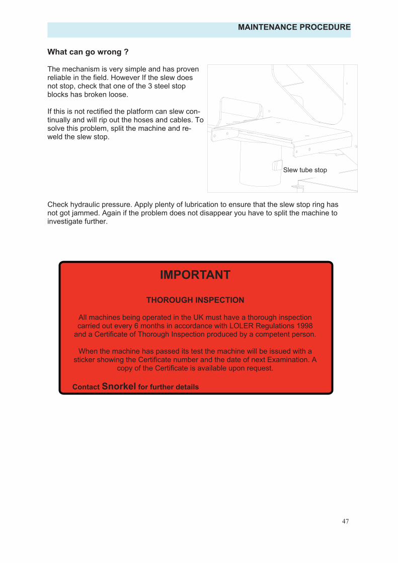
47
What can go wrong ?
The mechanism is very simple and has proven reliable in the field. However If the slew does not stop, check that one of the 3 steel stop blocks has broken loose.
If this is not rectified the platform can slew con-tinually and will rip out the hoses and cables. To solve this problem, split the machine and re-weld the slew stop.
Check hydraulic pressure. Apply plenty of lubrication to ensure that the slew stop ring has not got jammed. Again if the problem does not disappear you have to split the machine to investigate further.
Slew tube stop
MAINTENANCE PROCEDURE
IMPORTANT
THOROUGH INSPECTION
All machines being operated in the UK must have a thorough inspection carried out every 6 months in accordance with LOLER Regulations 1998
and a Certificate of Thorough Inspection produced by a competent person.
When the machine has passed its test the machine will be issued with a sticker showing the Certificate number and the date of next Examination. A
copy of the Certificate is available upon request.
Contact Snorkel for further details

Illustrated Parts List
513868-200 Page 1
CONTENTS
Page Number
Illustrated Mechanical Parts List 2
Electrical Parts List 27
Hydraulic Hose and Fittings Lists 29
Electrical Schematics Battery Power 33 Mains Power 34 Diesel/Petrol 35 Bi-Fuel Power 36
Hydraulic Schematics Battery/Mains Power 37 Diesel/Petrol 38 Bi-Fuel Power 39 Friction Drive Option 40

Illustrated Parts List
Page 2 513868-200
LIGHTING BOARD ASSEMBLY
Lighting Board Assembly
Item Part No. Description Qty.
1
2
5
1
34
67
512492-000513301-000513302-000513742-000513300-000
AMBER REFLECTOR 2RH LIGHT CLUSTERLH LIGHT CLUSTER
REGISTRATION LAMP MOUNTSREGISTRATION LAMP
1122
8
058490-016056069-005056066-005
SET SCREW, M5 x 16mm 4M5 FLAT WASHER 8M5 NYLOCK NUT 8
1
2
34
4
5 6 7 8
Marker Lamp Kit (NOT SHOWN)
Part No. Description Qty.
513836-000513836-001513839-000513838-000513492-000
Harness, Tow Hitch to Chassis 1Harness, Chassis to Side Marker Lamps
Harness, Rear Light to Registration LampHarness, Rear Light to Side Marker Lamp
Amber Marker Lamp
1226
513403-000 White Reflector 2512687-000 13 Pin Plug 1512689-000 8 Core Cable 10m

Illustrated Parts List
513868-200 Page 3
OUTRIGGER COMPONENTS
Outrigger Components
Item Part No. Description Qty.1 10-5069 Outrigger 42 10-5070 Outrigger Foot 43 13-3608 Outrigger Ram 44 22-5179 Outrigger Ram Cover 45 15-0886 Ram Cover Skid Pad 46 12-2054 Banjo Bolt 87 SB-030030 Bush 248 SP-016E216 Pin 49 SP-030D171 Pin 410 SP-030D203 Pin 411 SP-030K211 Pin 412 10-2672 Retaining Peg 16

Illustrated Parts List
Page 4 513868-200
CHASSIS COMPONENTS
1
2
3
45
6
7
89
10
11
12
13
1415
16
17
1819
20
21
2223
2425
2627
28

Illustrated Parts List
Page 5
Chassis Components
1
6 24-3998 Brake Rod 7 21-0855 Boom Retaining Pin 8 10-5068 Boom Lock 9 09-1273 Inlet Plug
10 09-1394 Inlet Plug Cap
13 508133-000 Bowden Cable 14 508134-000 Cable Bracket 15 508112-000 NATO Plug
19 11-3449 Bolt (M12 x 80mm) 20 08-0192 Slew Bearing/worm Drive c/w Motor 21 10-5271 Slew Limiting Ring 22 13-2537 Stabiliser Control Valve 23 25-0239 Levelling Bubble
03-0275/02 Wheel Nuts 03 0275/01 Wheel Studs
CHASSIS COMPONENTS
Brake Hub Components
Part No. Description Qty.14305.08 Knott 300 x 60 Std. Brake Assembly 2DPSM 63 90 10 Oil Seal 2368A / 362A Inner Bearing Cone/Cup 2LM501349 / 501310 Outer Bearing Cone/Cup 224929.03 Standard Brake Shoe 21053 08 Load Washer 2
1 513439-000 Chassis 2 508106-000 Towing Coupling 3 508107-000 Adjustable Jockey Wheel 4 513441-000 3000Kg Rubber Suspension Axle c/w Brake Cables 5 513443-000 215/75R16 Wheel Assembley (5 Stud)
11 513398-000 Cycle guard R/H 12 513397-000 Cycle guard L/H
16 513450-000 Mudguard Support Bracket L/H 513449-000 Mudguard Support Bracket R/H 17 513416-000 Mudguard Mount Bracket 513793-000 Mudguard Mount Bracket (Friction Drive units only)18 IT250 Mudguard
24 513403-000 White Marker Lamp 25 513492-000 Amber Marker Lamp 26 513522-002 Mudflap Bracket 27 513522-000 Mudflap 28 513522-001 Mudflap Support Bracket
Item Part No. Description Qty.
1 1 1 2 10 10 1 1 1 1 1 1 1 1 1 1 1 1 2 2 2 26 1 1 1 1 2
6
513868-200

Illustrated Parts List
Page 6 513868-000
Slew Components (Bi-Fuel Powered Machine)
.ytQ noitpircseD .oN traP metI
1 mroftalP welS 1705-01 1 1 revoC PRG 7410-61 2 1 revoC PRG 8410-61 3 4 egniH 8580-51 4 2 yatS revoC 7904-42 5 1 yarT kcap-rewoP 6625-01 6 1 yarT yrettaB 7625-01 7 1 ecarB ssorC 6755-22 8 4 v6 yrettaB 5811-90 9 2 srotcennoC rewoP yrettaB 9362-4600AT 01 1 eludoM remrofsnarT/regrahC mroftalP 0822-90 11 1 eldnaH pmup-dnaH 2/4510-91 21 1 pmup-dnaH 1/4510-91 31 1 kcap-rewoP 4510-91 41 1 rotcatnoC 8990-90 51 1 dlofinaM sciluardyH 9063-31 61 1 tsil straP( xoB lortnoC lacirtcelE 9362-20 71 1 revoC xoB lortnoC 1855-22 81 1 evlaV lortnoC esaB 8880-31 91 82 )mm58 x 21M( tloB 8443-11 02 2 geP gniniateR 2762-01 12 2 egraL - geP gniniateR 0882-42 22 1 niP 023D530-PS 32
24 21-0852 Pin 225 2-5577 Splash Guard 126 20-0055 Kubota OC60 diesel engine c/w stop/start kit 127 13-0529 In-Line Check Valve 228 13-1949 Bell Housing 129 13-1950 Flexible Coupling 130 13-3649 Pump 131 13-3650 Outlet Elbow 132 13-3651 Suction Elbow 133 10-5269 Engine Mounting Bracket 134 10-5270 Battery/Pump Cover 135 09-1009 Battery 12v 136 11-3438 Clamp Plate 237 22-5177 Battery Clamp Rod 238 09-1393 230vPlug 139 13-0146 3-way Valve 140 Engine Jump-start Battery Kit 1
G70241 Battery Disconnect Connector, Female 1 G70242 Battery Disconnect Connector, Male 1 G70243 Battery Disconnect Connector, Handle 1
41 508136-000 Hydraulic Tank Drain Kit 1
SLEW COMPONENTS (BI-FUEL POWER)

Illustrated Parts List
513868-200 Page 7
SLEW COMPONENTS (BI-FUEL POWER)

Illustrated Parts List
Page 8
Slew Components (Mains Powered Machine) .ytQ noitpircseD .oN traP metI
1 mroftalP welS 1705-01 1 1 revoC PRG 7410-61 2 1 revoC PRG 8410-61 3 4 egniH 8580-51 4 2 yatS revoC 7904-42 5 1 yarT kcaprewoP 6625-01 6 1 yarT yrettaB 7625-01 7 1 ecarB ssorC 6755-22 8 2 etalP tsallaB - 9 1 xoB lortnoC V032 - 01 1 kcaprewoP 5510-91 11 1 eldnaH pmupdnaH 2/4510-91 21 1 pmupdnaH 1/4510-91 31 1 revoC regrahC taolF 6155-22 41 1 regrahC taolF 7391-90 51 1 dlofinaM sciluardyH 9063-31 61 1 xoB lortnoC welS - 71 1 revoC xoB lortnoC 1855-22 81 1 evlaV lortnoC esaB 8880-31 91 82 tloB 8443-11 02 2 geP gniniateR 2762-01 12 2 egraL - geP gniniateR 0882-42 22 1 niP 023D530-PS 32 2 niP 2580-12 42
25 22-5508 Emergency Battery Holder 126 09-2087 Dry Battery 1
SLEW COMPONENTS (MAINS POWER)
513868-200

Illustrated Parts List
Page 9
Slew Components (Battery Powered Machine) .ytQ noitpircseD .oN traP metI
1 mroftalP welS 1705-01 1 1 revoC PRG 7410-61 2 1 revoC PRG 8410-61 3 4 egniH 8580-51 4 2 yatS revoC 7904-42 5 1 yarT kcaprewoP 6625-01 6 1 yarT yrettaB 7625-01 7 1 ecarB ssorC 6755-22 8 4 yrettaB 5811-90 9 1 eludoM rewoP regrahC 3661-90 01 1 remrofsnarT 5661-90 11 1 kcaprewoP 4510-91 21 1 eldnaH pmupdnaH 2/4510-91 31 1 pmupdnaH 1/4510-91 41 1 drauG hsalpS 7755-22 51 1 rotcatnoC 8990-90 61 1 dlofinaM sciluardyH 9063-31 71 1 xoB lortnoC welS - 81 1 revoC xoB lortnoC 1855-22 91 1 evlaV lortnoC esaB 8880-31 02 82 tloB 8443-11 12
2 geP gniniateR 2762-01 22 2 egraL - geP gniniateR 0882-42 32 1 niP 023D530-PS 42 2 niP 2580-12 52 2 etalP pmalC 8343-11 62 2 doR pmalC yrettaB 7715-22 72
SLEW COMPONENTS (BATTERY POWER)
513868-200

Illustrated Parts List
Page 10
Slew Components (Engine Powered Machine) .ytQ noitpircseD .oN traP metI
1 mroftalP welS 1705-01 1 1 revoC PRG 7410-61 2 1 revoC PRG 8410-61 3 4 egniH 8580-51 4 2 yatS revoC 7904-42 5 1 yarT kcaprewoP 6625-01 6 1 yarT yrettaB 7625-01 7 1 ecarB ssorC 6755-22 8 2 etalP tsallaB - 9 1 eguaG thgiS 30SH 01 1 knaT ciluardyH 0135-01 11 1 eldnaH pmupdnaH 2/4510-91 21 1 pmupdnaH 1/4510-91 31 1 reniartS noitcuS 9330-31 41 1 retliF eniL nruteR 3452-31 51 1 dlofinaM sciluardyH 9063-31 61 1 xoB lortnoC welS - 71 1 revoC xoB lortnoC 1855-22 81 1 evlaV lortnoC esaB 8880-31 91 82 tloB 8443-11 02
2 geP gniniateR 2762-01 12 2 egraL - geP gniniateR 0882-42 22 1 niP 023D530-PS 32 2 niP 2580-12 42 1 diL knaT 3165-22 52 1 )lorteP( enignE 4400-02 62 1 )leseiD( enignE 5500-02 62 2 evlaV kcehC eniL-nI 9250-31 72 1 gnisuoH lleB 9491-31 82 1 gnilpuoC elbixelF 0591-31 92 1 pmuP 9463-31 03 1 woblE teltuO 0563-31 13 1 woblE noitcuS 1563-31 23 1 tekcarB gnitnuoM enignE 9625-01 33 1 revoC pmuP/yrettaB 0725-01 43 1 yrettaB 9001-90 53
SLEW COMPONENTS (ENGINE POWER)
513868-200

Illustrated Parts List
Page 11
SLEW COMPONENTS (ENGINE POWER)
513868-200

Illustrated Parts List
Page 12
LOWER BOOM COMPONENTS
Lower Boom Components
.ytQ noitpircseD .oN traP metI
1 10-5072 Bottom Boom 12 10-5073 Tie Bar 13 10-5263 Vertical Boom 14 13-3607 Bottom Ram 15 13-3606 Top Ram 16 13-3604 Master Ram 17 21-0852 Pin 28 SP-035D201 Pin 19 21-0850 Pin 110 SP-030D320 Pin 111 SP-035D320 Pin 11213 SB-060060 Bush 814 SB-035035 Bush 615 SB-030030 Bush 216 SB-025025 Bush 217 10-2672 Retaining Peg 818 24-2880 Retaining Peg 219 15-0884 Boom Rest Pad 120 15-0883 Boom Rest Pad 1
513868-200

Illustrated Parts List
Page 13
TOP BOOM COMPONENTS
Top Boom Components .ytQ noitpircseD .oN traP metI
1 mooB poT 5705-01 1 1 mooB cipocseleT 6705-01 2 1 maR gnilleveL egaC 3063-31 3 1 maR epocseleT 5063-31 4 1 kcolB troppuS maR eleT 9980-51 5 1 daP raeW 1880-51 6 6 daP raeW 0880-51 7 1 daP raeW 5980-51 8 1 daP raeW 6980-51 9 2 daP raeW 2880-51 01 8 tuN gniniateR daP 2593-42 11 4 etalP peeK daP raeW 8315-01 21 1 niP 302D530-PS 31 1 niP 002D520-PS 41 1 niP 302D040-PS 51 1 niP 021A520-PS 61 1 niP 461D520-PS 71 8 geP gniniateR 2762-01 81 2 hsuB 030030-BS 91 2 hsuB 040040-BS 02 4 hsuB 520520-BS 12 1 yarT elbaC 1212-90 22 1 gniknurT esoH 9093-42 32 1 daP tseR mooB 3880-51 42 1 etelpmoC niahc-garD 9001-51 52
513868-200

Illustrated Parts List
Page 14
DROPNOSE COMPONENTS
Drop-nose Components
.ytQ noitpircseD .oN traP metI 2 mooB eson-porD 8705-01 1 1 tnardauQ 7705-01 2 1 maR eson-porD 2063-31 3 3 niP 002D520-PS 4 1 niP 612D030-PS 5 6 geP gniniateR 2762-01 6 21 hsuB 520520-BS 7
513868-200

Illustrated Parts List
Page 15
CAGE SUPPORT COMPONENTS
Cage Support Components
Item Part No. Description Qty.
1 10-5232 Pivot Support 12 10-5231 Cage Slew Pivot 13 10-5229 See-Saw Bracket 14 10-5230 Upper Link Bracket 15 SP-025D235 Pin 46 SP-025D330 Pin 17 SP-016B108 Pin 18 10-2672 Retaining Peg 99 SB-025015 Bush 8
10 SB-025025 Bush 211 SB-016020 Bush 412 04-0113 Thrust Washer 213 13-2403 Cage Rotation Ram 114 23-0031 Spring 215 11-3442 Bolt (M12 x 170mm) 2
513868-200

Illustrated Parts List
Page 16
STEEL CAGE COMPONENTS
513868-200

Illustrated Parts List
805 158-001 Page 17
Steel Cage Components
.ytQ noitpircseD .oN traP metI
1 egaC leetS 1025-01 1 1 roolF egaC 5605-22 2 5 etalP pmalC 8343-11 3 2 pmalC-U 508932-000 4 1 raB sseccA 508934-000 5 1 niP 201B610-PS 6 1 geP gniniateR 2762-01 7 1 troppuS lortnoC 6025-01 8 1 evlaV ertnec-revO elbuoD 6710-31 9 1 evlaV lortnoC 0022-31 01 1 revoC raeR 0735-22 11 1 etalP gniknalB 1065-22 21 1 )V011( tekcoS 6721-90 31
14 22-5543 Control Support Top Plate (Battery & Engine Powered) 1 1 DCR 000-041805 51 2 pmaL rekraM rebmA 6212-90 61 2 thgiL leviwS 9391-90 71
STEEL CAGE COMPONENTS

Illustrated Parts List
Page 18
GRP BASKET COMPONENTS
GRP Basket Components .ytQ noitpircseD .oN traP metI
1 teksaB PRG 4762-20 1 1 drauG sseccA 3065-22 2 1 troppuS teksaB 7135-01 3 1 niP 201B610-PS 4
1 geP gniniateR 2762-01 5 1 troppuS lortnoC 6025-01 6 1 evlaV ertnecrevO elbuoD 6710-31 7 1 evlaV lortnoC 0022-31 8 1 revoC raeR 0735-22 9 1 etalP gniknalB 1065-22 01 1 )V011( tekcoS 6721-90 11 1 )V032( tekcoS 2931-90 11
12 22-5543 Control Support Top Plate (Battery & Engine Powered) 1 1 )derewoP sniaM( etalP poT troppuS lortnoC 2455-22 21
12 22-5544 Control Support Top Plate (Mains Powered c/w Generator) 1
513868-200

Illustrated Parts List
Page 19
Outrigger Ram - 13-3608
.ytQ noitpircseD .oN traP metI
1 ylbmessA ebuT 1-8063-31 1 1 tiK laeS 1532-31 2 1 hsuB daeH 4001-31 3 2 evlaV kcehC OP 4060-31 4 1 tunkcoL 3790-31 5 1 notsiP 7001-31 6 1 recapS 3200040-SS 7 1 ylbmessA doR 2-8063-31 8
OUTRIGGER RAM COMPONENTS
513868-200

Illustrated Parts List
Page 20
BOTTOM RAM COMPONENTS
Bottom Ram - 13-3607 .ytQ noitpircseD .oN traP metI
1 ylbmessA ebuT 1-7063-31 1 1 tiK laeS 2790-31 2 1 hsuB daeH 8690-31 3 1 evlaV ertnec-revO 2930-31 4 1 evlaV rewoL ycnegremE 2/4742-31 5 1 dioneloS 0902-90 6 1 rotcennoC nnamhcsriH 77/5242-31 7 1 tunkcoL 3790-31 8 1 notsiP 1790-31 9 1 recapS 3430050-SS 01 1 ylbmessA doR 2-7063-31 11
513868-200

Illustrated Parts List
Page 21
TOP RAM COMPONENTS
Top Ram - 13-3606
Item Part No. Description Qty.
1 13-3606-1 Tube Assembly 12 13-0972 Seal Kit 13 13-0968 Head Bush 14 13-0392 Over-centre Valve 15 13-2474/2 Emergency Lower Valve 16 09-2090 Solenoid 17 13-2425/77 Hirschmann Connector 18 13-0973 Locknut 19 13-0971 Piston 110 SS-0500037 Spacer 111 13-3606-2 Rod 112 13-3606-3 Bearing 1
513868-200

Illustrated Parts List
Page 22
MASTER RAM COMPONENTS
Master Ram - 13-3604
.ytQ noitpircseD .oN traP metI
1 ylbmessA ebuT 1-4063-31 12 13-3603-3 1 tiK laeS
1 hsuB daeH 1601-31 3 1 tunkcoL 3790-31 4 1 notsiP 4601-31 5 1 ylbmessA doR 2-4063-31 6
513868-200

Illustrated Parts List
Page 23
TELESCOPE RAM COMPONENTS
Telescope Ram - 13-3605
Item Part No. Description Qty.1 13-3605-1 Tube Assembly 12 13-3605-3 Seal Kit 13 13-3605-4 Head Bush 14 13-0472 Over-centre Valve 15 13-0659 PO Check Valve 16 13-3605-5 Piston 17 13-3605-6 Locknut 18 13-3605-7 Spacer 19 13-3605-2 Rod Assembly 1
513868-200

Illustrated Parts List
Page 24
LEVELLING RAM COMPONENTS
Levelling Ram - 13-3603 .ytQ noitpircseD .oN traP metI
1 13-3603-1 Tube Assembly 12 13-3603-3 Seal Kit 13 13-1061 Head Bush 14 13-2489 Over-centre Valve 25 13-1064 Piston 16 13-0973 Locknut 17 13-3603-2 Rod Assembly 1
513868-200

Illustrated Parts List
Page 25
DROPNOSE RAM COMPONENTS
Drop-nose Ram - 13-3602 .ytQ noitpircseD .oN traP metI
1 13-3602-1 Tube Assembly 12 13-3603-3 Seal Kit 13 13-1061 Head Bush 14 13-2489 Over-centre Valve 25 13-1064 Piston 16 13-0973 Locknut 17 13-3602-3 Spacer 18 13-3602-2 Rod Assembly 1
513868-200

Illustrated Parts List
Page 26
CAGE ROTATION RAM COMPONENTS
Cage Rotation Ram - 13-2403 .ytQ noitpircseD .oN traP metI
1 13-2403-1 Tube Assembly 12 13-0993 Seal Kit 13 13-0988 Head Bush 14 13-0992 Piston 15 13-0994 Locknut 16 SS-0200020 Spacer 17 13-2403-2 Rod Assembly 1
513868-200

Illustrated Parts List
508158-001 Page 27
Electrical Parts Kit 02-2639 Location Part No. Description Qty.
Control Box TA0001-2639 Control Box Lable 1 Control Box TA0002-2639 Top Hat DIN Rail 0.3 Control Box TA0003-2639 SN04062K Weiland Safety Relay 2 Control Box TA0004-2639 4 AMP 1 Pole MCB Type C 2 Control Box TA0005-2639 Interface Relay Type P16 10 Control Box TA0006-2639 Entrelec 2.5mm Double Deck ISO Terminals 28 Control Box TA0007-2639 End Plate for TA0006 1 Control Box TA0008-2639 IN4001 Diode 4
Cage TA0009-2639 20 Way Connection Strip for P16 2 TA0010-2639 6A 250v AC with 391-8350-729 Actuator 1
Control Box TA0011-2639 M20 Gland (Black) 1 Hour Meter TA0012-2639 M/C Box PS111165 2 Hole 1
Cage TA0013-2639 Buzzer 1 Hour Meter TA0014-2639 PG09 Grey Locknut 2
Control Box & Cage TA0015-2639 Emergency Stop Button 2 Top Boom TA0016-2639 Limit Switch 1
TA0017-2639 PG09 Grey Gland 2 Control Box TA0018-2639 2 Pos.Stay-put Key 1
TA0019-2639 Booted Actuator 1 Hour Meter TA0020-2639 Hour Meter AC 2
TA0021-2639 3 POSITIVE LONG HANDLE 2 Outriggers TA0022-2639 Limit Switch 2 N/C 4
TA0023-2639 16mm Slit Conduit 25M Coil 1 Control Box & Cage TA0024-2639 40mm Mushroom Head Green Spring Button 2
TA0025-2639 Turret Head 4 TA0026-2639 4 Pin Male M12 Chassis Plug with M20 Thread 6
Control Box & Cage TA0027-2639 40mm Mushroom Head Black Spring Button 1 Control Box & Cage TA0028-2639 1 N/O Contact 5 Control Box & Cage TA0029-2639 2 N/O Contact 3 Control Box & Cage TA0030-2639 2 x N/C Contact 2 Control Box & Cage TA0031-2639 N/O ANS N/C CONTACTS 1 Control Box & Cage TA0032-2639 10 Way Jumper Bar 3 Control Box & Cage TA0033-2639 Red L.E.D. 2 Control Box & Cage TA0034-2639 Green L.E.D with Panel Mount Fitting 5
TA0035-2639 M12 ST FM 4 POLE 5M PUR 4 TA0036-2639 M12 5M BRAD H.LEAD 90 DEGREE 1 TA0037-2639 Terminal Devider 11
Control Box & Cage TA0038-2639 N/C Contact Block 1 Cage TA0039-2639 16mm Black Nylon Locknut 12 Cage TA0040-2639 M16 Gland Black 12 Cage TA0041-2639 Cable Gland 2 Cage TA0042-2639 Locknut 2

Illustrated Parts List
Page 28 508158-001
Electrical Parts Kit 02-2639 (Cont) Location Part No. Description Qty.
TA0047-2639 KA132000B9 Valve Plug 5
Control Box TA0050-2639 ABS Machined Enclosure 1
TA0054-2639 Blanking Plug 1
TA0055-2639 2 Position Key (spring to off) 1
Cage TA0056-2639 Key Selector Switch (3 Position) 1
Cage TA0057-2639 Green Push Button Switch 1
TA0058-2639 12 Way Terminal Block 15 AMP 2
TA0059-2639 1 N/O Add-on Contact 2
Cage TA0060-2639 Cage Control Plate 1
TA0064-2639 Battery Power Conectors 2
TA0065-2639 ETU 35 / 8 Non ROHS Compliant 4

Illustrated Parts List
Page 29
TL49J Basic Fittings Kit (All Specifications)
Part N° Description QTY.
12-1008 ¼” BSP Male x 7/16” JIC Male Straight Adaptor 29
12-1007 3/8” BSP Male x 7/16” JIC Male Straight Adaptor 41
12-1013 3/8” BSP Male x 9/16” JIC Male Straight Adaptor 10
12-1017 ½” BSP Male x 9/16” JIC Male Straight Adaptor 3
12-1869 ¼” BSP Male x 7/16” JIC Male Positional Elbow 6
12-1110 7/16” JIC Equal Tee Female-on-Run. 6
12-1501 ½” Dowty Washer 6
12-1502 3/8” Dowty Washer 64
12-1507 ¼” Dowty Washer 45
12-1511 1/8” Dowty Washer 1
12-1867 9/16” JIC Male/Female Elbow 1
12-2001 ½” BSP Male Plug 1
12-2003 3/8” BSP Male Plug 6
12-2002 1/8” BSP Male Plug 1
12-0927 9/16” UNF Male x 9/16” JIC Male Straight Adaptor 1
12-0916 ¼” BSP Male x ¼” BSP Female Straight Adaptor 1
12-1001 3/8” BSP Male x ¼” BSP Male Straight Adaptor 6
12-1502 3/8” Dowty Washer 6
12-1879 ¼” BSP Female x ¼” BSP Female Compact 90 deg Elbow 1
12-9005 ” BSP Male x 7/16” JIC Male Straight 25thou restrictor 43/812-9004 ” BSP Male x 7/16” JIC Male Straight 40thou restrictor 23/8
12-9007 ” UNF Male Plug 19/16
5063701 ” (-4) JIC Female Cap 17/16
513868-200

Illustrated Parts List
Page 30
Par
t
Num
ber
N°
Off
Loca
tion
Hos
e S
ize
End
Fitt
ings
Leng
thE
nd ‘A
’E
nd ‘B
'
G1
2O
utrig
ger V
alve
to O
utrig
ger R
am 1
¼ R
77/
16 J
IC F
emal
e S
traig
ht7/
16 J
IC F
emal
e 13
5 de
g30
00
G2
2O
utrig
ger V
alve
to O
utrig
ger R
am 2
¼ R
77/
16 J
IC F
emal
e S
traig
ht7/
16 J
IC F
emal
e 13
5 de
g31
00
G3
2O
utrig
ger V
alve
to O
utrig
ger R
am 3
¼ R
77/
16 J
IC F
emal
e S
traig
ht7/
16 J
IC F
emal
e 13
5 de
g18
00
G4
2O
utrig
ger V
alve
to O
utrig
ger R
am 4
¼ R
77/
16 J
IC F
emal
e S
traig
ht7/
16 J
IC F
emal
e 13
5 de
g17
00
G5
1O
utrig
ger V
alve
to M
anifo
ld P
¼ R
77/
16 J
IC F
emal
e S
traig
ht7/
16 J
IC F
emal
e S
traig
ht17
00
G6
1O
utrig
ger V
alve
to T
ank
Man
ifold
¼ R
77/
16 J
IC F
emal
e S
traig
ht7/
16 J
IC F
emal
e S
traig
ht17
00
G7
2B
ase
Valv
e to
Bot
tom
Ram
¼ R
77/
16 J
IC F
emal
e S
traig
ht7/
16 J
IC F
emal
e S
traig
ht15
00
G8
1B
otto
m R
am E
mer
genc
y Lo
wer
¼ R
77/
16 J
IC F
emal
e S
traig
ht7/
16 J
IC F
emal
e S
traig
ht15
30
G9
2B
ase
Valv
e to
Top
Ram
¼ R
77/
16 J
IC F
emal
e S
traig
ht7/
16 J
IC F
emal
e S
traig
ht67
00
G10
1To
p R
am E
mer
genc
y Lo
wer
¼ R
77/
16 J
IC F
emal
e S
traig
ht7/
16 J
IC F
emal
e S
traig
ht68
00
G11
2B
ase
Valv
e to
Tel
esco
pe R
am¼
R7
7/16
JIC
Fem
ale
Stra
ight
7/16
JIC
Fem
ale
Stra
ight
6900
G12
1Te
lesc
ope
Ram
Dra
in¼
R7
7/16
JIC
Fem
ale
Stra
ight
7/16
JIC
Fem
ale
Stra
ight
6900
G13
1B
ase
Val
ve P
to M
anifo
ld G
P3 / 8
702
9/16
JIC
Fem
ale
Stra
ight
9/16
JIC
Fem
ale
Stra
ight
1200
G14
2B
ase
Val
ve to
Man
ifold
Sle
w T
ee¼
R7
7/16
JIC
Fem
ale
Stra
ight
7/16
JIC
Fem
ale
90 d
eg10
00
G15
1H
and-
pum
p to
Man
ifold
HP
1¼
R7
7/16
JIC
Fem
ale
90 d
eg7/
16 J
IC F
emal
e S
traig
ht70
0
G16
2S
lew
Mot
or to
Man
ifold
SLA
/SLB
¼ R
77/
16 J
IC F
emal
e 90
deg
7/16
JIC
Fem
ale
90 d
eg12
00
G17
2B
ase
Valv
e to
Dro
p-no
se R
am¼
R7
7/16
JIC
Fem
ale
Stra
ight
7/16
JIC
Fem
ale
Stra
ight
1820
0
G18
2B
aske
t Val
ve to
Bot
tom
Ram
¼ R
77/
16 J
IC F
emal
e S
traig
ht7/
16 J
IC F
emal
e S
traig
ht17
800
G19
2B
aske
t Val
ve to
Man
ifold
Sle
w T
ee¼
R7
7/16
JIC
Fem
ale
Stra
ight
7/16
JIC
Fem
ale
Stra
ight
1870
0
G20
1B
aske
t Val
ve P
to M
anifo
ld C
P3 / 8
702
9/16
JIC
Fem
ale
Stra
ight
9/16
JIC
Fem
ale
Stra
ight
1870
0
G21
1Ta
nk M
anifo
ld to
Man
ifold
T3 / 8
702
9/16
JIC
Fem
ale
Stra
ight
9/16
JIC
Fem
ale
Stra
ight
600
G22
1Ta
nk M
anifo
ld to
Bas
e V
alve
T3 / 8
702
9/16
JIC
Fem
ale
Stra
ight
9/16
JIC
Fem
ale
Stra
ight
370
G23
1P
ump
to M
anifo
ld P
3 / 8 70
2 9/
16 J
IC F
emal
e S
traig
ht9/
16 J
IC F
emal
e 90
deg
400
G24
1Ta
nk M
anifo
ld to
Filt
er3 / 8
702
9/16
JIC
Fem
ale
Stra
ight
9/16
JIC
Fem
ale
Stra
ight
1000
513868-200

Illustrated Parts List
513868-200 Page 31
Par
t
Num
ber
N°
Off
Loca
tion
Hos
e S
ize
End
Fitt
ings
Le
ngth
'B‘ dn
E ’
A‘ dnE
G26
1B
aske
t Val
ve to
Tan
k M
anifo
ld3 / 8 70
29/
16 J
IC F
emal
e S
traig
ht
9/16
JIC
Fem
ale
Stra
ight
18
300
G27
2B
aske
t Val
ve to
Top
Ram
¼ R
7 7/
16 J
IC F
emal
e S
traig
ht
7/16
JIC
Fem
ale
Stra
ight
12
700
G28
2B
aske
t Val
ve to
Tel
esco
pe R
am¼
R7
7/16
JIC
Fem
ale
Stra
ight
7/
16 J
IC F
emal
e S
traig
ht
1200
0
G29
2M
aste
r Ram
to D
OC
Val
ve¼
R7
7/16
JIC
Fem
ale
Stra
ight
7/
16 J
IC F
emal
e S
traig
ht
1210
0
G30
1B
aske
t Val
ve to
Sle
win
g R
am¼
R7
7/16
JIC
Fem
ale
Stra
ight
7/
16 J
IC F
emal
e 90
deg
23
00
G31
1B
aske
t Val
ve to
Sle
win
g R
am¼
R7
7/16
JIC
Fem
ale
Stra
ight
7/
16 J
IC F
emal
e 90
deg
22
00
G32
2B
aske
t Val
ve to
Dro
p-no
se R
am¼
R7
7/16
JIC
Fem
ale
Stra
ight
7/
16 J
IC F
emal
e 90
deg
41
00
G33
2D
OC
Val
ve to
Bas
ket L
evel
ling
Ram
¼ R
7 7/
16 J
IC F
emal
e S
traig
ht
7/16
JIC
Fem
ale
90 d
eg
3900
G34
2B
aske
t Val
ve to
DO
C V
alve
¼ R
7 7/
16 J
IC F
emal
e S
traig
ht
7/16
JIC
Fem
ale
90 d
eg
600
H1
1P
ump
to M
anifo
ld¼
R7
9/16
JIC
Fem
ale
Stra
ight
7/
16 J
IC F
emal
e 90
deg
30
0
H2
1E
ngin
e P
ump
to M
anifo
ld T
ee¼
R7
9/16
JIC
Fem
ale
Stra
ight
9/
16 J
IC F
emal
e 90
deg
12
00
H3
1E
ngin
e P
ump
to T
ank
Suc
tion
Por
t½
R1A
T1/
2 B
SP
Fem
ale
Stra
ight
1/
2 B
SP
Fem
ale
90 d
eg
1940
H14
1P
ress
ure
Rel
ief V
/V to
Tan
k¼
R7
9/16
JIC
Fem
ale
90 d
eg
9/16
JIC
Fem
ale
Stra
ight
10
60

Illustrated Parts List
Page 32 513868-200
TL49
J Fr
ictio
n D
rive
kit 1
3-36
70Li
nden
Par
t No
Des
crip
tion
Qty
H41/
4 1S
N 9/
16 J
IC F
STR
X 9
/16
JIC
F 9
0 20
01
H51/
4 1S
N 9/
16 J
IC F
45
X 9/
16 F
90
215
1
H61/
4 1S
N 9/
16 J
IC F
STR
X 9
/16
JIC
F 9
0 19
01
H71/
4 1S
N 9/
16 J
IC F
45
X 9/
16 F
90
250
1
H81/
4 1S
N 9/
16 J
IC F
45
X 9/
16 F
90
1525
2
H91/
4 1S
N 9/
16 J
IC F
45
X 9/
16 F
90
1650
2
H10
3/8
1SN
9/16
JIC
F S
TR X
9/1
6 JI
C F
45
3275
1
H11
3/8
1SN
9/16
JIC
F S
TR X
9/1
6 JI
C F
90
3275
1
H12
1/4
1SN
9/16
JIC
F S
TR X
9/1
6 JI
C F
STR
910
2
H13
1/4
1SN
9/16
JIC
F S
TR X
9/1
6 JI
C F
STR
122
01

TL4
9J
Bat
tery
Po
wer
Dec
06
02-2
634

TL4
9J
Mai
ns
Pow
er
Ap
ril 0
5

TL4
9J
En
gin
e Po
wer D
ec 0
6

MOTORRUN
LEG
EN
DP
LATE
RE
F.18
-088
3
(EN
ER
GIS
EFO
R(E
NE
RG
ISE
TOE
NA
BLE
(EN
ER
GIS
ETO
SE
LEC
TS
OL3
EM
ER
GE
NC
YLO
WE
RIN
GV
ALV
E
18-cx1.5mm2H07x22mLONG
3-c
x2.
5mm
2H
07x
26m
LON
G
CO
LOU
R-C
OD
ED
7-c
x1m
m2
x26
mLO
NG
TRA
ILE
RLI
GH
TS
110V
16A
SO
CK
ET
RAMTOP
SW
8
RAMBTM
EM
'YLW
R1
1
2
OFF2
(TO
PB
OO
MLI
FTR
AM
)
EM
ER
GE
NC
YLO
WE
RIN
GV
ALV
E(B
OTT
OM
BO
OM
LIFT
RA
M)
BA
SE
CO
NTR
OLS
)C
AG
EC
ON
TRO
LS)
LIG
HTI
NG
PLU
G
110V
16A
INLE
T
STA
BIL
ISE
RS
)
PB
6
EN
GIN
E
OFF
/ON
3-P
OS
STA
Y-PU
TKE
YS
W11
PO
WE
RS
ELE
CT
CEN
TRE
RE
MO
VAL
ON
LY
OFF
1
2
1
2
ENG12
BATT
ENGINE
STO
P
PB
4E
STO
P &
EN
GIN
ES
TAR
T
DE
AD
MA
NP
B5
OVERLOADFLASHINGRED
GREEN
POWERON
SP
RIN
G-T
O-O
FF
SW
102-
PO
SK
EY
OV
ER
-RID
E
LP6
LP1
STABILISERSELECT
BASESELECT
DUMPVALVECLOSE
OFF
COILPOWERSUPPLY
SO
L4
CO
NTR
OLS
SE
LEC
TOR
VA
LVE
SO
L1S
OL5
DU
MP
VA
LVE
BTM
2
1
RAM EM
'YLW
R
1
SO
L2 DIV
ER
TER
VA
LVE
DIS
CO
NN
EC
TB
ATT
ER
Y
CH
AR
GE
RLE
AD
S
+24V
MOTORSTART
0VTOP
SW
2
2RAM
D1
D2
CAGEDEADMAN
D3
EN
AB
LE
STA
BV
ALV
E
PB
3
GR
EE
N
ENGINESTART
(ENERGISETORUN)ENGINESTOP
{RE
F:ZC
KM
7H29
}
STA
RTE
RS
WIT
CH
CA
GE
LOA
D-S
EN
SIN
GS
WIT
CH
AC
R:R
ED
RF
US
IBLE
LIN
K
CAG
E
CA
GE
BO
XC
OV
ER
PLA
TE
SW
9
(0.5
SQ
)
STA
RT
ER
MO
TOR
Y :
YE
LLO
W
S :
SK
Y
W:W
HIT
E
G :
GR
EE
N
50
30
19B
/R
B/WR
OC
60D
IES
EL
LIVEFEED
CH
AR
GIN
G
(IFF
ITTE
D)
LAM
P
RG
LOW
PLU
G
B/W
B :
BLA
CK
BL
:BLU
ER
/W
B/R
RE
GU
LA
TOR
B
BL
B
BL
SS
RG
FLY
WH
EE
LG
EN
ER
ATO
R
FU
SE
(15A
)
TIM
ER
STO
P
B3
12
4Y
SO
LEN
OID
ENERGISETORUN
+12VDC
GROUND
START
STA
RTE
RM
OTO
R
2-P
OS
STA
Y-PU
TKE
YR
EM
OV
AL
EIT
HER
POS
SE
LEC
TOR
CO
NTR
OLS
FLASHINGRED
OVERLOAD
MO
TOR
DE
AD
MA
NS
TAR
T/
PB
2
GX
270
PE
TRO
L
LP7
AW
D
BA
TTE
RY
+VE
SO
LEN
OID
+VE
D4
CAGE
PB
1U
NIT
A2
RL7
A1
ES
TOP
&
ENGINE
BASE
POS1SHOWN
EN
GIN
ES
TOP
2 1
SW
1
3231
CO
NTR
OL
SA
FETY
14
BO
OM
SW
ITC
H(S
HO
WN
OFF
PR
OP
)
SW
7
GR
EE
NLP
5
SW
6
IGN
ITIO
NC
OIL
+VE
BA
TTE
RY
-VE
13S
33S
34
GLOWPLUG
GRND
+12VDC
START
STOP
DIE
SE
LO
NLY
LEGALARMCANCEL
STABILISERLEGSWITCHES
SW
5
LP4
GR
EE
N
GR
EE
NLP
3
SW
4
LP2
BA
SELE
GE
ND
PLA
TER
EF.
18-0
907
SW
3
S21
S11
S12
S22
S31
S35
UN
IT
RL8
A2
A1
S35
S31
S34
S33
SA
FETY
CO
NTR
OL
32311413
S12
S22
S21
S11
MIC
RO
SW
ITC
H(O
PTI
ON
AL)
FRIC
TIO
ND
RIV
EV
ALV
E
SW
12
(ENGINE)HOURMETER
(BATTERYPOWERPACK)HOURMETER
TL49
J
Jan
08

TL4
9J
Bat
tery
/Mai
ns
Pow
er
Jun
e 05

Jun
e 05
TL49
J D
iese
l/Pet
rol P
ower
ed

TL4
9J
Bi-
Fuel
Po
wer
ed
Jun
e 05

July
07
TL4
9J
Bi-
Fuel
wit
h fr
icti
on
dri
ve o
pti
on


Local Distributor / Lokaler Vertiebshändler / Distributeur localEl Distribuidor local / ll Distributore locale
EUROPE, MIDDLE EASTAFRICA & ASIA
PHONE: +44 (0) 845 1550 057FAX: +44 (0) 845 1557 756
NORTH & SOUTH AMERICAPHONE: +1 785 989 3000
TOLL FREE: +1 800 225 0317FAX: +1 785 989 3070
AUSTRALIAPHONE: +61 2 9725 4000
FAX: +61 2 9609 3057
NEW ZEALANDPHONE: +64 6 3689 168
FAX: +64 6 3689 164