particle accelerators projects in iran (focused on the ipm ... · particle accelerators projects in...
TRANSCRIPT

Particle Accelerators Projects in Iran
(Focused on the IPM recent and
future projects)
Hamed Shaker
School of Particles and Accelerators, Institute for Research in
Fundamental Sciences (IPM)

History
During 90s, the idea of founding of a particle accelerator national
laboratory and to participate in the international particle accelerator
projects was born among a few Iranian physicists. At the beginning of
this century, this dream turned to reality, mostly under the IPM’s
umbrella. At 2001 and 2005, respectively, the official collaboration
with CERN and SESAME was signed. At 2003, a low energy TW electron
linear accelerator project was started which aimed at a proof of
principle and using as an injector for other accelerators at the one
hand and for the industrial and clinical applications at the other hand.
At 2004, the accelerator physics Ph.D. program was started at IPM and
12 students were graduated up to now. At 2009, the national particle
accelerator laboratory was founded aimed at to build a light source
although the initial idea was a collider.

Institute for Research in Fundamental
Science (IPM)
The Institute was founded on 1989 and it is comprised of nine schools:
• Astronomy
• Biological Sciences
• Cognitive Sciences
• Computer Science
• Mathematics
• Nano-science
• Particles and Accelerators
• Philosophy
• Physics
• National Projects
• Iranian Light Source Facility (ILSF)
• Observatory
• GRID
Pioneer of the accelerator physics PhD
program in Iran
IPM E-Linac & Iranian Light Source
Facility (ILSF) accelerator projects
CERN & IPM collaboration (officially
signed at 2001 by the ministry of
science), with the CMS experiment
Collaboration with CERN
CMS
CLIC
LINAC4
TW Low Energy Electron Linac
Ph.D. Programs: Was started from 2004 and 12 students
were graduated.
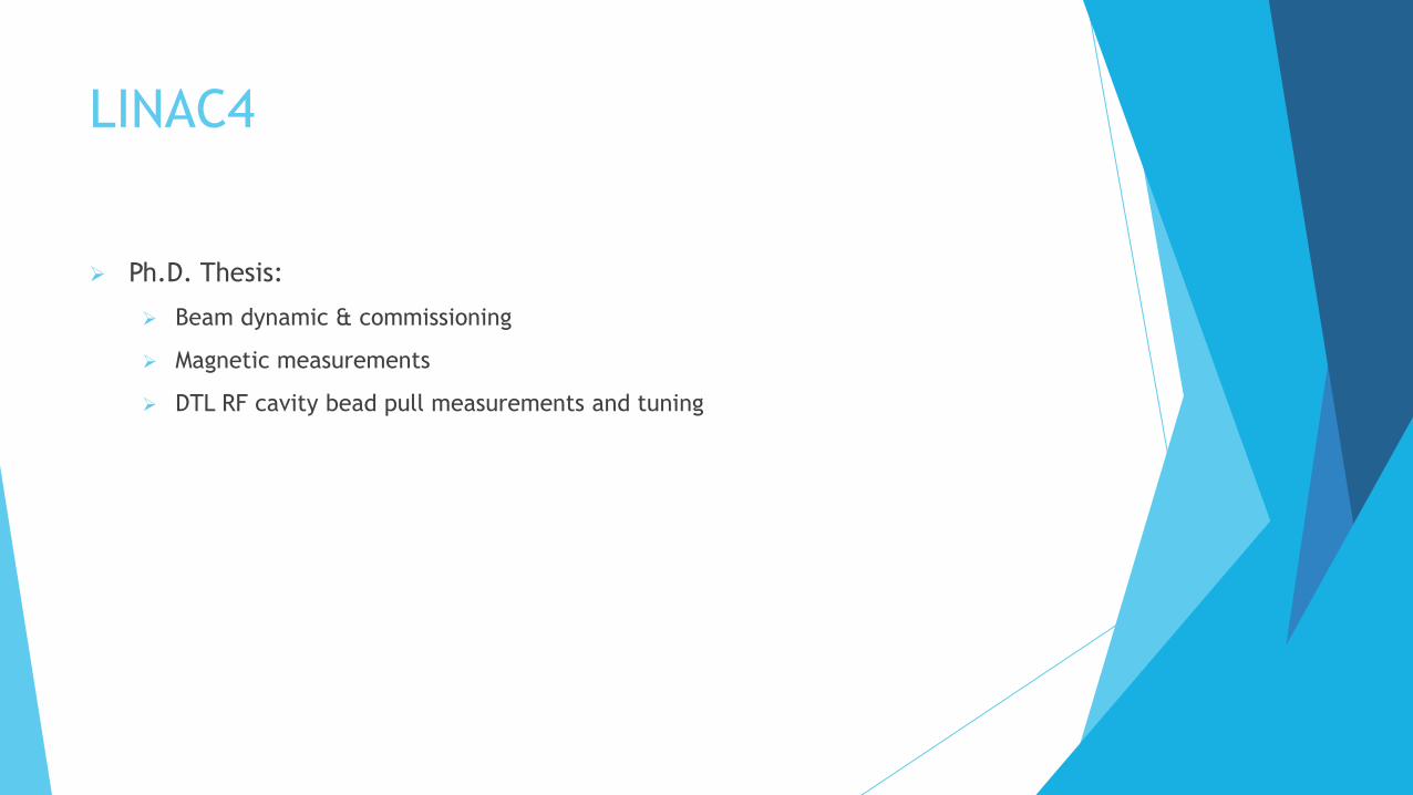
LINAC4
Ph.D. Thesis:
Beam dynamic & commissioning
Magnetic measurements
DTL RF cavity bead pull measurements and tuning
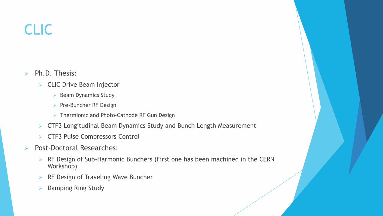
CLIC
Ph.D. Thesis:
CLIC Drive Beam Injector
Beam Dynamics Study
Pre-Buncher RF Design
Thermionic and Photo-Cathode RF Gun Design
CTF3 Longitudinal Beam Dynamics Study and Bunch Length Measurement
CTF3 Pulse Compressors Control
Post-Doctoral Researches:
RF Design of Sub-Harmonic Bunchers (First one has been machined in the CERN Workshop)
RF Design of Traveling Wave Buncher
Damping Ring Study

CLIC Drive Beam Front-End Layout
Gun Gun Sub Harmonic Bunchers
Sub Harmonic Bunchers
Pre Buncher
Pre Buncher
TW Buncher TW Buncher Accelerating Structures Accelerating Structures
Solid state amplifier, 500 MHz
Solid state amplifier, 500 MHz
Modulator-Klystrons, 1 GHz, 20 MW Modulator-Klystrons, 1 GHz, 20 MW
~ 140 KeV ~ 140 KeV ~ 12.2 MeV ~ 12.2 MeV
Gun Sub Harmonic Bunchers
Pre Buncher
TW Buncher Accelerating Structures
Solid state amplifier, 500 MHz
Modulator-Klystrons, 1 GHz, 20 MW
~ 140 KeV ~ 12.2 MeV
Diagnostics
~ 2.4 MeV ~ 4.6 MeV ~ 8.4 MeV
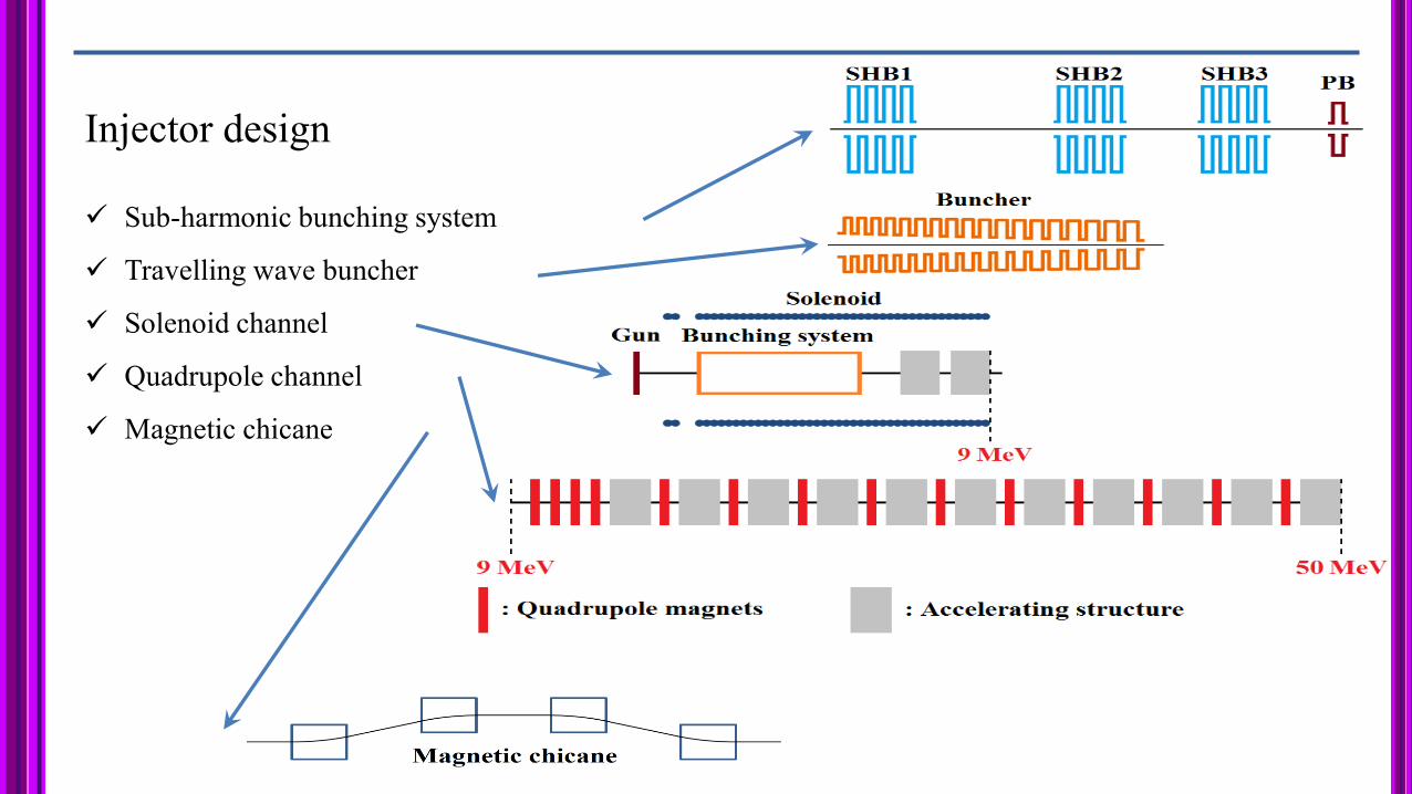
Injector design
Sub-harmonic bunching system
Travelling wave buncher
Solenoid channel
Quadrupole channel
Magnetic chicane

Longitudinal phase space evolution: SHB
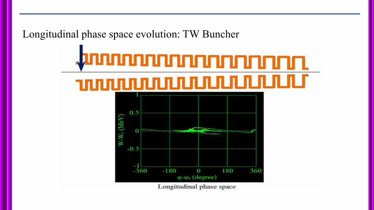
Longitudinal phase space evolution: TW Buncher

Longitudinal phase space evolution: Accelerating structures
CLIC Drive Beam Injector – Electron
Guns and Prebuncher
Low Emittance
Thermionic Gun
Low Emittance
Photo-Cathode RF Gun Pre-Buncher
𝐹𝑟𝑒𝑞𝑢𝑒𝑛𝑐𝑦 𝐺𝐻𝑧 1
𝐵𝑢𝑛𝑐ℎ 𝐹𝑟𝑒𝑞𝑢𝑒𝑛𝑐𝑦 [𝐺𝐻𝑧] 0.5
𝐶𝑢𝑟𝑟𝑒𝑛𝑡 𝐴 /𝐶ℎ𝑎𝑟𝑔[𝑛𝐶] 4.2/8.4
𝑅𝑀𝑆 𝐵𝑢𝑛𝑐ℎ 𝐿𝑒𝑛𝑔𝑡ℎ 𝑝𝑠 5
𝑃𝑢𝑙𝑠𝑒 𝑅𝑒𝑝𝑒𝑡𝑎𝑡𝑖𝑜𝑛 𝑅𝑎𝑡𝑒 [𝐻𝑧] 50
𝐼𝑛𝑝𝑢𝑡 𝑃𝑜𝑤𝑒𝑟 [𝑀𝑊] 20,30,40
𝑃𝑢𝑙𝑠𝑒 𝐿𝑒𝑛𝑔𝑡ℎ [𝜇𝑆] 140

CLIC Drive Beam Injector – Sub Harmonic
Bunchers
Low filling time (wideband structure)
Coupler asymmetrical field compensation
Beam Loading Compensation
Reduced required input power: For a FTW structure about 1MW is needed for 40KV voltage
Frequency [MHz] 499.75
Bandwidth [MHz] ~60
Filling time [ns] ~10
Input Power [KW] ~20-100
Maximum Voltage [KV] 15-45
Phase advance [Deg] ~108
Phase/Group Velocity 0.62c/0.14c

CLIC Drive Beam Injector – TW Buncher
1,2E+09
1,25E+09
1,3E+09
1,35E+09
1,4E+09
1,45E+09
1,5E+09
1,55E+09
1,6E+09
0 20 40 60 80 100 120 140 160 180 200
frequency (
Hz)
Phase Advance (degree)
Dispersion diagram for the first dipole mode
0
1
2
3
4
5
6
7
2 3 4 5 6 7 8 9 10 11 12 13 14 15 16 17
Group velocity/c (%)
0
20
40
60
80
100
120
140
160
180
2 3 4 5 6 7 8 9 10 11 12 13 14 15 16 17
r/Q (Ω/m)

Iranian Light Source Facility (ILSF)
7th Users’ Meeting , 20-21 April2015, Qazvin, Iran

Preliminary
scientific case
Draft Conceptual
design
Conceptual Design
published
Feasibility studies (Site
selection, Capacity
building , Final CDR,
Project planning)
R&D
Prototype
Light Source
Operation
(7 beam lines)
Revised
(cost estimate/
schedule) Input from
Users’
community
Machine
construction &
commissioning
Detailed
engineering
design
Basic design
R&D
Prototype
Input from
Users’
community
Vice president for
Science&Technology
Steering
Committee
IPM
R&D
Prototype
Input from
Users’
community Project
Approval by
Government
R&D
Prototype
Phase 0
Phase 1
Phase 2
Phase 3
Phase 4
Phase 5
Phase 6
Milestone
Project Milestones

Iranian Light Source Facility
Iranian
ParticleAcceleratorConference
nd2 25 - 26 Nov. 2015
ILSF Organization Chart

Main Building Architecture - Ground Floor Main Building Architecture - Ground Floor Ground Floor Overall information:
• Total area: 26320 m2
• Experimental Hall: 9700m2
• Accelerator Tunnel: 5550m2
• Service area:4975m2
• Access Corridors: 2323m2
• Support Labs/work offices… :3785m2
Including:
• 22 Support Laboratories/Work offices
• 4 meeting rooms
• 10 entrances including 3equipment
entrance from outer perimeter
• 5 equipment entrance from inner yard
• Stair cases/Washrooms/Pantries/WCs

First Floor Overall information:
• Total area: 12650 m2
• Service area:4525m2
• Access Corridors: 2285m2
• Support Labs/work offices… :5840m2
Including:
• 27 Support Laboratories/Work offices
• 1 meeting room
• Control room
• 20 PCDR (power supply, control & diagnostic instrument room)
• 20 AHU rooms
• 5 Switchgear rooms
• 3 Access bridge
• Stair cases/Washrooms/Pantries/WCs
Main Building Architecture - First Floor Main Building Architecture - First Floor

ILSF Site Ground

Site Layout - Buildings Schedule Site Layout - Buildings Schedule
Area(m2) Building No.
38000 Main building 1
3500 Administration building 2
3000 R&D Laboratory 3
4500 Utility building 4
1000 Workshop 5
500 Canteen building 6
250 Mosque 7
3000 Guesthouse 8
1500 Amphitheater & Library 9
1500 Recreation complex 10
- Gridiron 11
150 HSE building 12
200 Fire station 13
500 Power generator building 14
500 Nitrogen production unit 15
500 Water tanks 16
250 Pump house 17
500 Rainwater harvesting tank 18
1500 Warehouse 19
150 Substation building 20
150 Passage post building 21
100 Gas pressure reduction station 22
300 Security building 23
75 East Guardhouse 24
75 South Guardhouse 25
61700 Total

ILSF storage ring lattice design
Parameter Unit Value
Energy GeV 3
Maximum beam current mA 400
Circumference m 528
Length of straight section m 7.0
Natural emittance pm rad 275
Betatron tune (Qx/Qy) -/- 44.20/16.23
Natural chromaticity (ξx/ξy) -/- -108.30/-61.54
Natural energy loss/turn keV 406
RF frequency MHz 100

ILSF R&D Laboratory
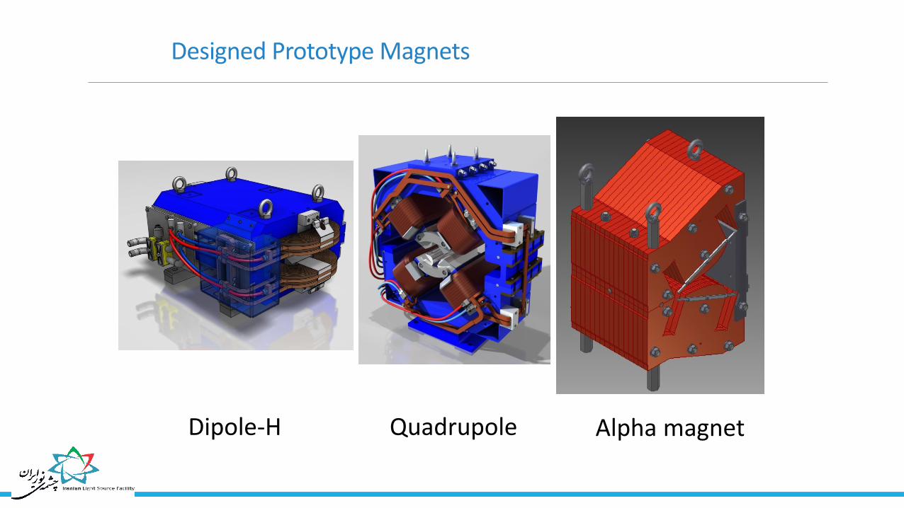
Designed Prototype Magnets
Dipole-H Quadrupole Alpha magnet

Constructed Prototype Magnets
Dipole-H Quadrupole Alpha magnet

Ongoing Prototypes construction
High Field Insert Dipole + Special Girder
Quadrupole
Sextupole
PHYSICAL REVIEW SPECIAL TOPICS - ACCELERATORS AND BEAMS 18, 082401 (2015)
Dipole
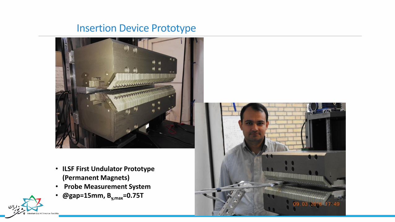
Insertion Device Prototype
• ILSF First Undulator Prototype (Permanent Magnets)
• Probe Measurement System • @gap=15mm, By,max=0.75T

Temperature controlled hutch for magnet measurements

RF R&D Status High Power RF Amplifier 4kW 500MHz SSA prototype
(developed successfully, 59% efficiency)
30kW 100MHz SSA prototype as one forth of 120kW (under investigation)
Amplifier Module (Based on BLF578 Transistor)
8:1 Combiner
1:8 Divider
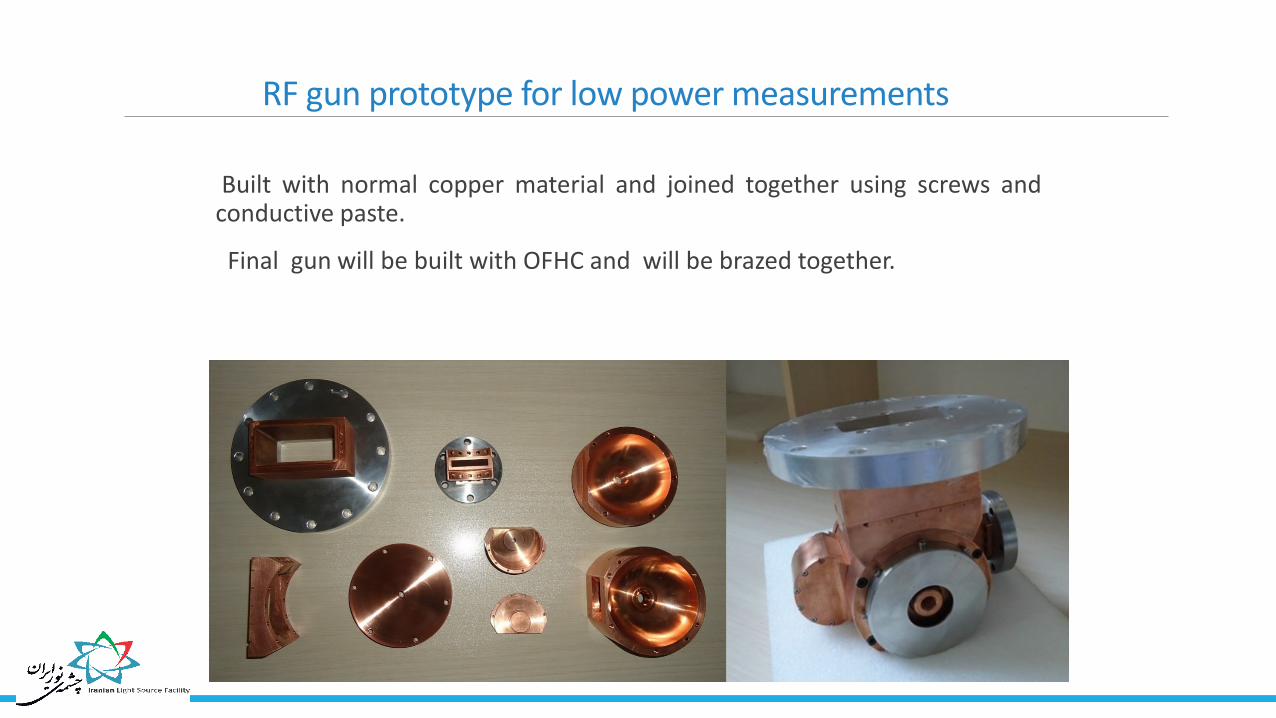
RF gun prototype for low power measurements
Built with normal copper material and joined together using screws and conductive paste.
Final gun will be built with OFHC and will be brazed together.

Simulation and measurement results
Parameter Unit Simulation Measurement
Resonance frequency
MHz 2859.38 2859.57
Unloaded quality factor
- 13200 9300
Shunt impedance
MΩ/m 86.2 60.4
unloaded coupling (S11)
dB -20 -19.6

100 MHz Cavity Electromagnetic & mechanical design
Feasibility study & RFP preparation
Fabrication is initiated.
100 MHz Cavity under construction by local industry
Longitudinal E-field for 1W RF input
cavity body thermal analysis cavity coupler thermal analysis
Parameter SuperFish HFSS CST
Resonant
frequency
99.8
MHz
101.427
MHz
100.388
MHz
Q factor 20425 21434 21390
Shunt
impedance 2.16 MΩ 1.75 MΩ 1.75 MΩ
Cavity simulation results comparison

List of beam instrumentations
Instrument Name Detecting Parameters Required
Number
Estimated Cost
$
Beam Position Monitor Position
400 3,800,000
Stripline BPM 7 126,000
Faraday Cup
Current-Charge
1 10,000
Fast Current Transformer 12 180,000
Wall Current Monitor 8 8,000
Beam Charge Monitor 5 75,000
DC Current Transformer 2 100,000
Annular Electrode 2 20,000
Fluorescent Screen/OTR
Profile-Size
13 50,000
Visible Synch.Rad.Monitor 3 250,000
X-Ray Synch.Rad.Monitor 1 10,000
Beam Loss monitors Beam loss 129 129,000
Scrapers Beam halo-others 4 20,000
Total Estimated
Cost 5,000,000$ Almost 80% costs of the
instrumentations are for BPMs!!

Beam position Monitor of ILSF
BPM
Button Test Stand Electronic Readout
Design & Fabrication
done successfully Design is done
successfully
BPM resolution should be at least 1 µm
Beam displacement is less than 20 µm
Beam size is 60×6 µm2
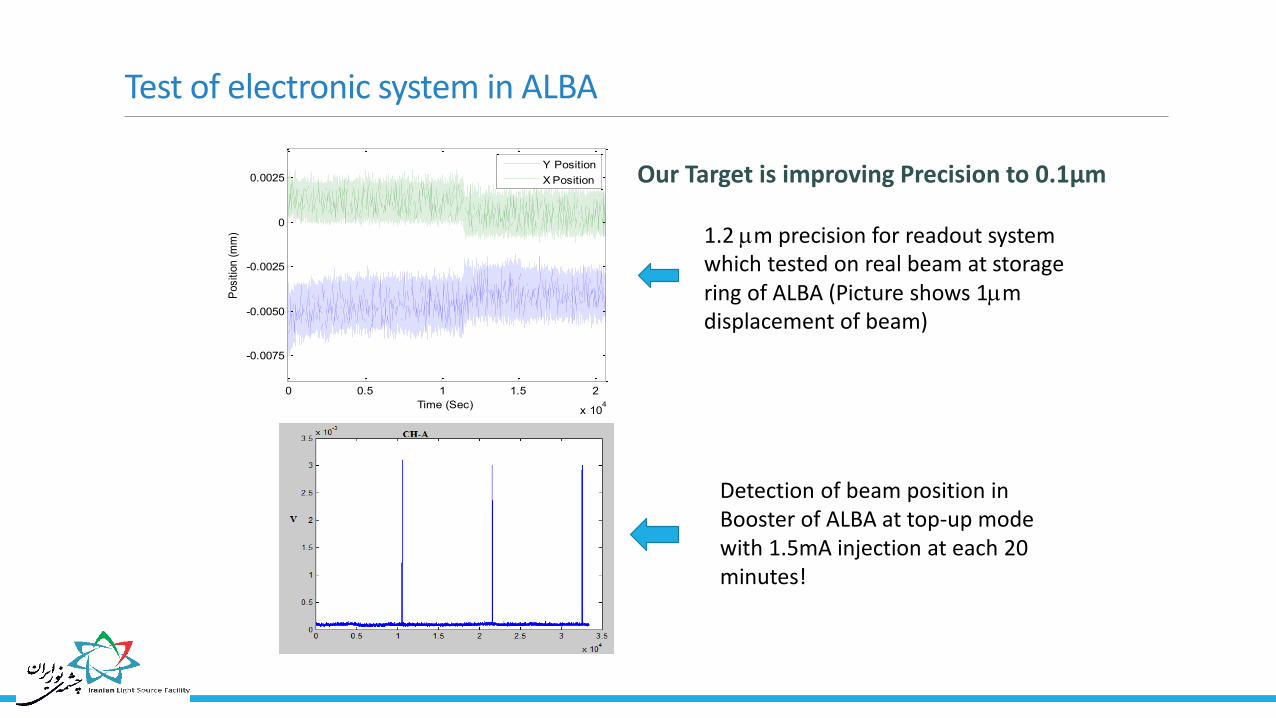
Test of electronic system in ALBA
0 0.5 1 1.5 2
x 104
-0.0075
-0.0050
-0.0025
0
0.0025
Positio
n (
mm
)
Time (Sec)
Y Position
X Position
1.2 m precision for readout system which tested on real beam at storage ring of ALBA (Picture shows 1m displacement of beam)
Detection of beam position in Booster of ALBA at top-up mode with 1.5mA injection at each 20 minutes!
Our Target is improving Precision to 0.1μm

Low Energy TW Linear Accelerator

IPM LINAC Layout

IPM Linac Parameters
Parameter Magnitude Unit
Electron Gun Output Energy 45 KeV
Electron Gun Maximum Current 10 mA
Working Frequency 2997.9 MHz
Phase Advance between cells 90 Degrees
RF input peak power 2 MW
Maximum Repetition Rate 250 MHz
Maximum Pulse Length 7 µs
Buncher output beam energy 1.4 MeV
Buncher Length 30.8 cm
Accelerating Tube Length 60 cm
Final Energy (two / three tubes) 8 / 11 MeV
Cells Quality Factor 11000

Beam Dynamic Study - I
4
5
6
7
0 5 10 15 20E 0
(M
eV)
ξ=z/λ0
0,5
1
0 1 2 3
βw
ξ=z/λ0
Inside the buncher, phase velocity increases smoothly to reach to the velocity of light.
After choosing phase velocity inside the buncher, the accelerating field (without loss)is calculated using this equation. The disk hole radius(a) is equal to 10.00 mm.
With power loss
Without power loss

-150
-100
-50
0
50
100
0 5 10 15 20
Δ (
Deg
ree
)
ξ=z/λ0
Beam Dynamic Study - II
End of the Buncher
End of the 1st Tube
End of the 2nd Tube
End of the 3rd Tube
-97.24±7.54 deg (final distribution) ≈ 4.2 mm bunch length Capturing: -142 … 102 : 244 deg (68%) Continues beam is entered: No pre-buncher is assumed.
Look at slide 4

Beam Dynamic Study - III
0
2
4
6
8
10
12
0 5 10 15 20
Kin
etic
En
ergy
(M
eV)
ξ=z/λ0
End of the Buncher
End of the 1st Tube
End of the 2nd Tube
End of the 3rd Tube
Final Kinetic Energy: 11.04±0.26 MeV or 2.3% Energy Spread

Coupler asymmetry
1.1 Induced kick
Necessity of 3D modeling ⟹ ASTRA

New buncher design
2.1 The need for a new buncher
History of the buncher design.
𝜎𝜑 = 15.2°
𝜎𝐸𝑘= 0.61 𝑀𝑒𝑣
𝜎𝜑 = 11.3°
𝜎𝐸𝑘= 0.41 𝑀𝑒𝑣
𝐿𝐵 = 40 𝑐𝑚 𝐿𝐵 = 50 𝑐𝑚
Distortion of the geometry of some cells of the existing buncher through the fabrication process.
The feasibility of cavity fabrication using the brazing techniques.
Looking for a new design with higher performance (higher beam quality) and no kick.

2.3 New buncher
Beam parameters and comparison with previous designs
L = 40 cm (Pre-buncher included)
𝜎𝜑 = 9.2°
𝜎𝐸𝑘= 0.30 𝑀𝑒𝑉
𝜎𝜑 = 7.0°
𝜎𝐸𝑘= 0.17 𝑀𝑒𝑉
𝐸𝑎𝑣 = 8.0 𝑀𝑒𝑉 𝐸𝑎𝑣 = 7.5 𝑀𝑒𝑉
Larger phase acceptance
New buncher design
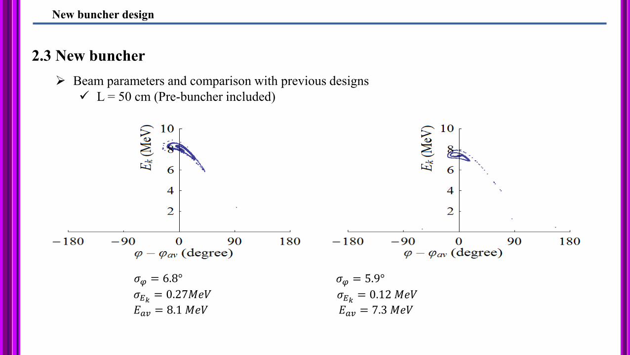
2.3 New buncher
Beam parameters and comparison with previous designs
L = 50 cm (Pre-buncher included)
𝜎𝜑 = 6.8°
𝜎𝐸𝑘= 0.27𝑀𝑒𝑉
𝜎𝜑 = 5.9°
𝜎𝐸𝑘= 0.12 𝑀𝑒𝑉
𝐸𝑎𝑣 = 8.1 𝑀𝑒𝑉 𝐸𝑎𝑣 = 7.3 𝑀𝑒𝑉
New buncher design

3.3 Misalignment Studies
𝐵 ≈ 1200-800 G
Solenoid channel
No misalignment
𝜀 ~ 5 mm-mrad
Offset
𝜀 500%
Tilt
𝜀 300%

3.3 Misalignment Studies
Offset
Solenoid channel
𝐵 ≈ 1200-800 G 𝐵 20% (≈ 1000-650 G) 𝐵 40% (≈ 700-500 G)
55% Beam loss

3.3 Misalignment Studies
What to do?
1. Extend the strange buncher field sligthly more. Then the beam dynamics will be less sensitive to
misalignments!
Solenoid channel
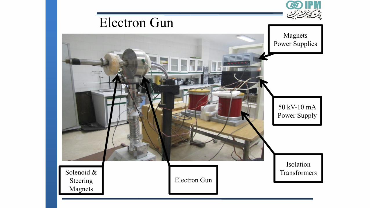
Electron Gun
50 kV-10 mA
Power Supply
Magnets
Power Supplies
Isolation
Transformers Solenoid &
Steering
Magnets
Electron Gun

RF (Klystron, Modulator, Waveguide)
Linac Laboratory at IPM

RF Transmission Components

The Linac Bunker

The accelerating tube layout
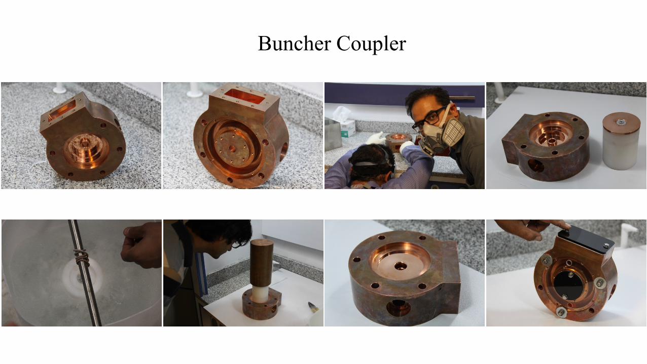
Buncher Coupler

Accelerating Structure (Tube) Coupler

Buncher

Accelerating Structure (Tube)
Three units was constructed
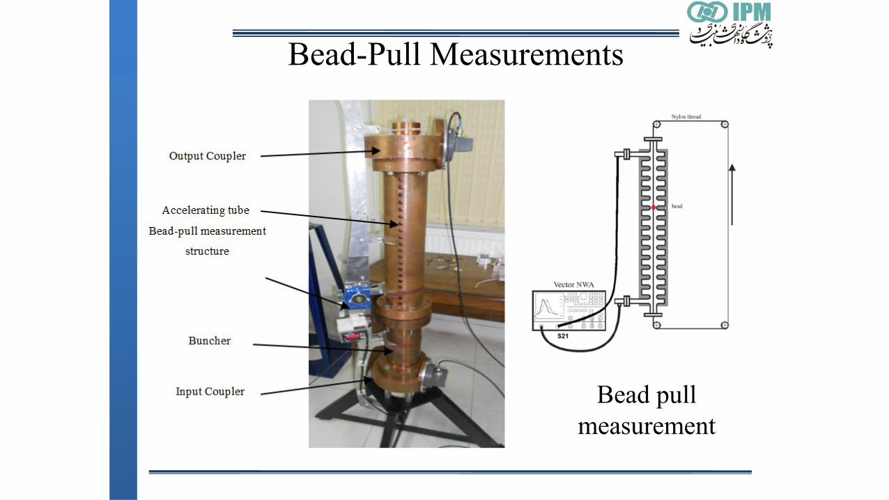
Bead pull
measurement
Bead-Pull Measurements

Frequency Measurements-Direct Method

Pre-Buncher

Ideas for the future projects
Photo-Cathode RF Gun
THz Source
Inverse-Compton Scattering

Project in the Progressive Stages Photo-Cathode RF Gun and THz Source
Photocathode RF Gun
Accelerating structures from IPM’s LINAC
UV Laser 1-12 ps - ~ 1 mJ
Modulator
Klystron
Pulse Compressor
Undulator Experiment
Electrons
X-ray
15 MW peak power modulator is built and available.
24 or 12MeV
Modulator
Klystron – S band
(~5 MW)
With and without pulse compressor
Has several applications like the MeV ultrafast electron diffraction
Study is required to show that the amount of short range wakefield is acceptable for IPM’s LINAC accelerating structures
Magnet

Project in the Progressive Stages Inverse-Compton Scattering X-Ray Source
Photocathode RF Gun
Accelerating structures from IPM’s LINAC
UV Laser 1-12 ps - ~ 1 mJ
Modulator
Klystron
Pulse Compressor
Interaction Point
IR Laser ~ 50fs - ~ 0.5 J
Ψ
Magnet Detector
Electrons
X-ray
15 MW peak power modulator is built and available.
24 or 12MeV
Bunch Compressor
Modulator
Klystron – S band
(~5 MW)
With and without pulse compressor
Short storage ring ( ~ 10-20m) could be used to increase average x-ray flux
Beauty of this project: We will have output for scientist in each step and further upgrades are possible like laser/plasma acceleration and …
3 MeV : Entrance of the X-ray 30 MeV: Entrance of the Hard X-ray
90 MeV: Entrance of the Gamma-ray

Inverse-Compton Scattering X-ray source
Photocathode RF Gun
Accelerating Structures S,C or X bands
UV Laser 1-12 ps - ~ 1 mJ
Modulator
Klystron
Pulse Compressor
Interaction Point
IR Laser ~ 50fs - ~ 0.5 J
Ψ Ψ= 180° (Thomson Backscattering): Maximum Photon Energy and
number Ψ= 90° : shorter photon pulse length
with half energy and less number because transverse bunch size is so
shorter than its longitudinal size
Magnet Detector
Electrons
X-ray
15 MW peak power modulator is built and available.
50-200MeV
𝜆 𝐴 =1300
1 − 𝑐𝑜𝑠𝜓
𝜆0[𝜇𝑚]
𝐸𝑏2[𝑀𝑒𝑉]
𝐸𝑏 = 50 𝑀𝑒𝑉 , 𝜆0 = 800𝑛𝑚𝜆 = 0.2𝐴 , 𝐸𝑝 ≈ 60 𝐾𝑒𝑉
In synchrotron light sources with conventional undulator about 8.4 GeV beam energy in needed to produce this photon energy (undulator period =1 cm and k=0.5)
Laser works similar to anundulator with 4 orders less in periodic length
Bunch Compressor
Laser works similar to anundulator with 4 orders less in periodic length

Thanks for your attention

Constant beam size schemes
Target beam size of 0.5 mm & 1 mm & 2 mm
Target beam size 0.5 mm 1 mm 2 mm
Beam loss 3.6% 16% 22%
Average Magnetic field 1400 G 835 G 689 G
Final emittance 10 mm-mrad 19 mm-mrad 70 mm-mrad
Beam loss distribution
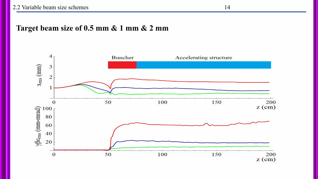
2.2 Variable beam size schemes 14
Target beam size of 0.5 mm & 1 mm & 2 mm