partial knee system - cayenne medicalcayennemedical.com/downloads/mirror surgical technique...
TRANSCRIPT

Partial Knee System
Unicondylar Surgical Technique
520-1115-00 Rev MCat. No. 400008

Cayenne Medical, Inc. - A Zimmer Biomet Company16597 North 92nd St, Suite 101
Scottsdale, AZ 85260cayennemedical.com
1.888.229.3661
Page 2
MIRROR Surgical Technique

Page 3
MIRROR Surgical Technique
Contents
Indications and Contraindications 4
Introduction 5
Mirror Partial Knee System 6
Procedure Overview 7
Initial Incision 8
Tibial Preparation 9
Femoral Preparation 16
Femoral Implant Sizing 25
Drill or Punch Tibial Holes 26
Implant Trials 27
Cement Fixation 28
Lateral Uni Considerations 30
Femoral Component Dimensions 31
Tibial Baseplate Dimensions 32
Poly Component Dimensions 33
Instrument List 34
Implant Part Numbers 35

Page 4
MIRROR Surgical Technique
Indications and Contraindications
The Mirror™ Partial Knee System by Cayenne Medical, Inc. is intended for arthroplasty of either the medial or lateral tibiofemoral compartment of the knee with the following indications:
• Non-inflammatory degenerative joint disease including post-traumatic arthritis and osteoarthritis.
• Failed previous implant.
• Correctable deformity.
• All Mirror Partial Knee System implants are intended for cemented use only.
• Implant components of this system are designed for single use and to be used as a system.
The Mirror Partial Knee System is contraindicated in:
• Infection, sepsis, or infections with potential to spread to the implant site.
• Patients incapable of or unwilling to comply with surgeon instructions, including ability to maintain weight and limit activity.
• Osteomalacia, insufficient bone stock, excessive bone loss or bone resorption apparent on roentgenogram.
• Deficient or absent ACL, PCL or collateral ligament; incomplete or deficient soft tissue.
• Neuropathic joint, vascular insufficiency or muscular atrophy.
• Skeletal immaturity.
• Severe varus or valgus deformity.
• Severe extension or flexion contracture.

Page 5
MIRROR Surgical Technique
Introduction
BackgroundLigament guided surgery utilizes the patient’s unique knee motion to guide preparation of the femoral condyle in unicompartmental knee arthroplasty (partial knee replacement). This surgical technique describes the procedure and instrumentation for implanting the Mirror™ Partial Knee System.
The Mirror Partial Knee System combines proven implant design features with a straightforward and repeatable surgical technique to enhance implant positioning and soft tissue balancing. The materials used in the Mirror Partial Knee System, as well as the articular compliance and bone fixation, are based on review of long-standing unicompartmental implant designs with proven clinical outcomes.1,2,3,4,5,6,7,8 The Mirror Partial Knee System is composed of unicompartmental femoral components and unicompartmental tibial components designed for cement fixation. These components may be used to create a replacement of the medial or lateral tibiofemoral compartment. Mirror Partial Knee System components include individually sterile-packaged femoral components made of cobalt-chromium alloy and Modular Tibial Baseplates made of titanium alloy used with ultra-high molecular weight polyethylene Tibial Inserts.
The Mirror Partial Knee System instrumentation system utilizes cutting elements supported on the resected tibial plateau to prepare the femoral condyle. The tibiofemoral compartment is dynamically distracted during condyle preparation to provide optimal ligament balance throughout range of motion.
For medial tibiofemoral compartmental arthritis, the compartment is exposed through a medial parapatellar incision and medial arthrotomy. The Mirror Partial Knee System, instrumentation and surgical technique can be used for lateral compartment partial knee replacement; however, the lateral compartment is technically more challenging and should not be attempted until experience has been gained with medial compartment partial knee replacement.1 Argenson JN, Parratte S, Flecher X, Aubaniac JM, Unicompartmental Knee Arthroplasty: Technique Through a Mini-incision Clinical Orthopaedics
and Related Research 2007; 464:32-36.2 Argenson JN, Komistek RD, Aubaniac JM, Dennis DA, Northcut EJ, Anderson DT, Agostini S. In vivo determination of knee kinematics for subjects
implanted with a unicompartmental arthroplasty. J Arthroplasty. 2002;17:1049–1054.3 Berger RA, Meneghini RM, Jacobs JJ, Sheinkop MB, Della Valle GJ, Rosenberg AG, Galante JO. Results of unicompartmental knee arthroplasty at
a minimum of ten years of follow-up. J Bone Joint Surg Am. 2005;87:999–1006.4 Fuchs S, Rolauffs B, Plaumann T, Tibesku CO, Rosenbaum D., Clinical and functional results after the rehabilitation period in minimally-invasive
unicondylar knee arthroplasty patients. Knee Surg Sports Traumatol Arthrosc. 2005;13:179–186.5 Hollinghurst D, Stoney J, Ward T, et al. No deterioration of kinematics and cruciate function 10 years after medial unicompartmental
arthroplasty. Knee. 2006;13:440-4.6 Newman J, Pydisetty RV, Ackroyd C. Unicompartmental or total knee replacement: The 15-year results of a prospective randomized controlled
trial. J Bone Joint Surg Br. Jan 2009; 91-B;1:52-57.7 McAllister CM. The role of unicompartmental knee arthroplasty versus total knee arthroplasty in providing maximal performance and
satisfaction. J Knee Surg. 2008;21:286-292.8 Walton NP, Jahromi I, Lewis PL, et al. Patient-perceived outcomes and return to sport and work: TKA versus mini-incision unicompartmental knee
arthroplasty. J Knee Surg. 2006;19:112-16.
Page 6
MIRROR Surgical Technique
Mirror Partial Knee System
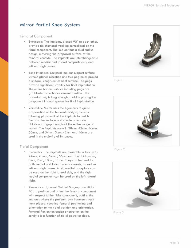
Femoral Component• Symmetric: The implants, placed 90° to each other,
provide tibiofemoral tracking centralized on the tibial component. The implant has a dual radius design, matching the prepared surface of the femoral condyle. The implants are interchangeable between medial and lateral compartments, and left and right knees.
• Bone Interface: Sculpted implant support surface without planer resection and two peg holes proved a uniform, congruent cement surface. The pegs provide significant stability for final implantation. The entire bottom surface including pegs are grit blasted to enhance cement fixation. The posterior peg is long enough to aid in placing the component in small spaces for final implantation.
• Versatility: Mirror uses the ligaments to guide preparation of the femoral condyle, thereby allowing placement of the implants to match the articular surface and create a uniform tibiofemoral gap throughout the entire range of motion. The implants come in 38mm, 42mm, 46mm, 50mm, and 54mm. Sizes 42mm and 46mm are used in the majority of instances.
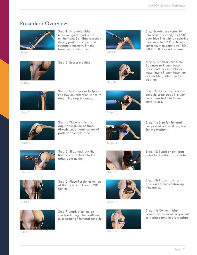
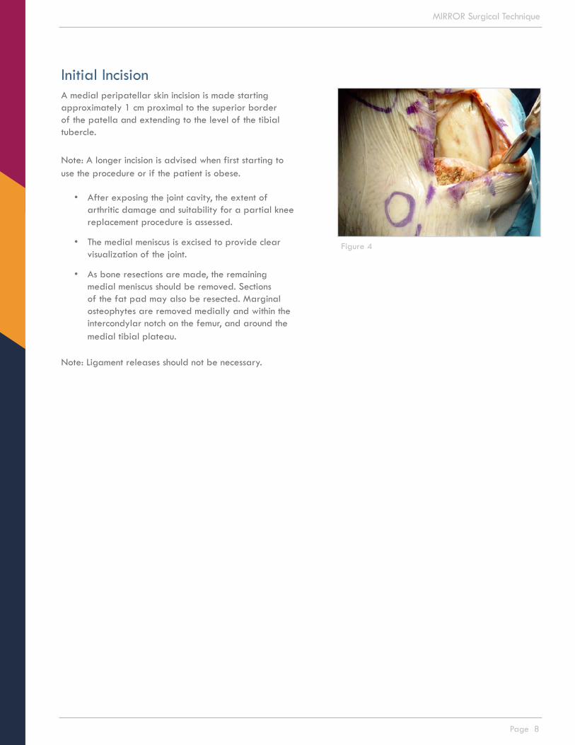
Tibial Component• Symmetric: The implants are available in four sizes
44mm, 48mm, 52mm, 56mm and four thicknesses, 8mm, 9mm, 10mm, 11mm. They can be used for both medial and lateral compartments, as well as left and right knees. A left medial baseplate can be used on the right lateral side, and the right medial component can be used on the left lateral tibia.
• Kinematics: Ligament Guided Surgery uses ACL/PCL to position and orient the femoral component with respect to the tibial component, putting the implants where the patient’s own ligaments want them placed, coupling femoral positioning and orientation to the tibial position and orientation. Femoral flexion/extension orientation on the condyle is a function of tibial posterior slope.
Figure 1
Figure 2
Figure 3
Page 7
MIRROR Surgical Technique
Step 1: Assemble tibial resection guide and place it on the tibia. Set tibia resection depth, posterior slope, and sagittal alignment. Pin the tower and cutting block.
Step 2: Resect the tibia.
Step 3: Insert spacer lollipop into flexion/extension space to determine gap thickness.
Step 4: Place and impact adjustable guide on tibia, directly underneath center of posterior condyle at 90°.
Step 5: Slide and lock the Balancer with shim into the adjustable guide.
Step 6: Place Positioner on top of Balancer with knee in 90° flexion.
Step 7: Mark blue line on condyle through the Positioner, over center of femoral condyle.
Step 8: Advance cutter bit into posterior condyle at 90° over blue line with bit spinning. Flex knee to 120° with cutter spinning, then extend to 180°. STOP CUTTER and remove.
Step 9: Transfer shim from Balancer to Planer base, insert and lock into Planer base. Insert Planer base into adjustable guide to locked position.
Step 10: Resurface femoral condyle using steps 1-6 with cutter inserted into Planer cutter block.
Step 11: Size for femoral component and drill peg holes for the implant.
Step 12: Punch or drill peg holes for the tibia baseplate.
Step 13: Place trials for tibia and femur, confirming kinematics.
Step 14: Cement tibial baseplate, femoral component and place poly into baseplate.
Procedure Overview
Step 1 Step 8
Step 2 Step 9
Step 3 Step 10
Step 4 Step 11
Step 5 Step 12
Step 6
Step 7
Step 13
Step 14
Page 8
MIRROR Surgical Technique
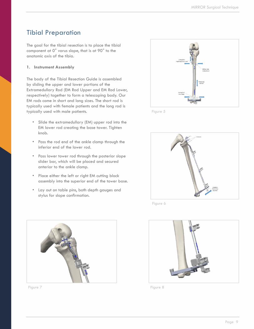
Initial IncisionA medial peripatellar skin incision is made starting approximately 1 cm proximal to the superior border of the patella and extending to the level of the tibial tubercle.
Note: A longer incision is advised when first starting to use the procedure or if the patient is obese.
• After exposing the joint cavity, the extent of arthritic damage and suitability for a partial knee replacement procedure is assessed.
• The medial meniscus is excised to provide clear visualization of the joint.
• As bone resections are made, the remaining medial meniscus should be removed. Sections of the fat pad may also be resected. Marginal osteophytes are removed medially and within the intercondylar notch on the femur, and around the medial tibial plateau.
Note: Ligament releases should not be necessary.
Figure 4
Page 9
MIRROR Surgical Technique
Tibial Preparation
The goal for the tibial resection is to place the tibial component at 0° varus slope, that is at 90° to the anatomic axis of the tibia.
1. Instrument Assembly
The body of the Tibial Resection Guide is assembled by sliding the upper and lower portions of the Extramedullary Rod (EM Rod Upper and EM Rod Lower, respectively) together to form a telescoping body. Our EM rods come in short and long sizes. The short rod is typically used with female patients and the long rod is typically used with male patients.
• Slide the extramedullary (EM) upper rod into the EM lower rod creating the base tower. Tighten knob.
• Pass the rod end of the ankle clamp through the inferior end of the lower rod.
• Pass lower tower rod through the posterior slope slider bar, which will be placed and secured anterior to the ankle clamp.
• Place either the left or right EM cutting block assembly into the superior end of the tower base.
• Lay out on table pins, both depth gauges and stylus for slope confirmation.
Figure 5
Figure 6
Figure 8Figure 7

Page 10
MIRROR Surgical Technique
2. Place assembled guide on tibia
The assembled tibial resection guide is place on the operative leg by placing the ankle clamp around the ankle. The guide body is aligned with the anatomic axis of the tibia by positioning the body of the guide in a sagittal plane as indicated by the tower of the ankle clamp aligning with the second toe with the leg in neutral position.
• Engage ankle clamp first by placing it around the ankle. Extend the tower rods such that the cutting block becomes positioned on the anterior cortex of the tibia.
• Holding the assembled guide in place, lock the telescoping rods in the tower by tightening the lower knob.
• Slide the assembled tower to align the rods with the mechanical axis of the tibia and second toe.
• Rotate the knob to lock tower in place.
• Advance anchor pin into tibia, through only pin hole in tower.
• Slide the lower end of the tower around the ankle medially and laterally to set varus and valgus of the cutting block.
• Adjust the slope by sliding the lower end of the rod away from the ankle.
• Confirm posterior slope using the inserting the stylus through the cutting slot and along the medical aspect of the tibial plateau for a medial uni, or lateral aspect for a lateral uni.
• To adjust posterior slope, move the guide body anteriorly on the tower and locking it in place.
• Place anchor pin in cutting block after all adjustments have been made.
Figure 9
Figure 10

Page 11
MIRROR Surgical Technique
NOTE: References for the posterior slope include two to three finger width under the distal end of the guide body, aligning the guide body with the long axis of the fibula, approximating the slope by the angle between the guide body and anterior surface of the tibia. The guide is positioned to recreate natural posterior slope of the tibial plateau. Typically it is in the range of 4° to 8°.
• Select either 2/4mm or 3/5mm depth gauge and attach to top of tower rod by turning knob.
• Place depth gauge into the cutting block slot in preferred location and orientation.
NOTE: The Resection Block slot and cutting surfaces are oriented at 90° to the axis of the Tibial Resection Guide body. There is no varus/valgus or posterior slope built in to the instrumentation and cutting block.
NOTE: The guide labeled TRG - Depth Guide 4 mm will resect 2 mm deeper than the 2mm TRG-Depth Guide. This places the position of the tibial resection 4 mm below the tip of the stylus when cutting through the slot and 2 mm below the tip of the stylus when cutting on the top surface of the block. The tip of the guide is placed in the tibial defect and the appropriate resection depth selected.
Figure 12
Figure 11

Page 12
MIRROR Surgical Technique
3. Resect the tibial plateau
• First use the reciprocating saw to perform the sagittal cut. Place the saw blade along the medial aspect of the intercondylar notch, just medial to the ACL attachment point on the tibial spine, which will maximize the size and depth of the tibial base.
NOTE: It may be necessary to remove osteophytes from this area to position the saw blade prior to making this cut.
• This resection is advanced to the top surface of the resection block taking care not to cut beyond the anticipated posterior slope of the transverse resection.
NOTE: Avoid undercutting the tibial eminence as this might weaken support of the anterior cruciate ligament. Avoid overcutting the sagittal resection as this might weaken support of the tibial component.
NOTE: The appropriate oscillating saw blade is 1.24 mm (.050”) thick by 13mm (½”) wide by 75 mm (3”) long.
NOTE: Be careful not to tip the distal end of the reciprocating saw blade down into the tibia, which could lead to a stress riser and or fracture.
• Second, perform the transverse cut by placing the oscillating saw blade in the slot provided by the cutting block.
• Remove the tower of the tibial resection guide, leaving the cutting block in place.
• Remove the resected piece using 1” straight or curved osteotome by sliding it up the radius of the femoral condyle.
Figure 13
Figure 14
Figure 15
Page 13
MIRROR Surgical Technique
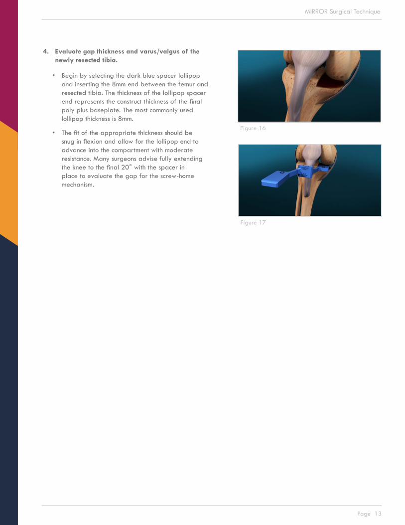
4. Evaluate gap thickness and varus/valgus of the newly resected tibia.
• Begin by selecting the dark blue spacer lollipop and inserting the 8mm end between the femur and resected tibia. The thickness of the lollipop spacer end represents the construct thickness of the final poly plus baseplate. The most commonly used lollipop thickness is 8mm.
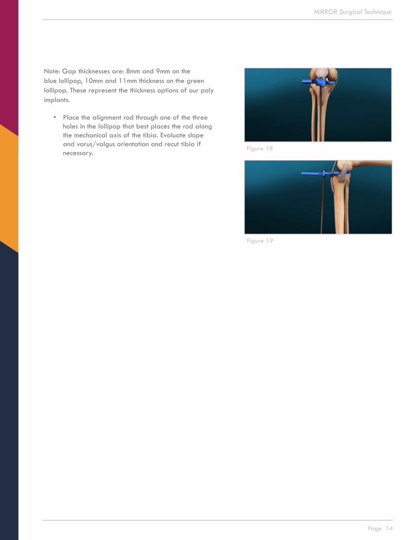
• The fit of the appropriate thickness should be snug in flexion and allow for the lollipop end to advance into the compartment with moderate resistance. Many surgeons advise fully extending the knee to the final 20° with the spacer in place to evaluate the gap for the screw-home mechanism.
Figure 16
Figure 17
Page 14
MIRROR Surgical Technique
Note: Gap thicknesses are: 8mm and 9mm on the blue lollipop, 10mm and 11mm thickness on the green lollipop. These represent the thickness options of our poly implants.
• Place the alignment rod through one of the three holes in the lollipop that best places the rod along the mechanical axis of the tibia. Evaluate slope and varus/valgus orientation and recut tibia if necessary.
Figure 18
Figure 19

Page 15
MIRROR Surgical Technique
NOTE: To fine tune the tibial resection, be sure to remove all obstructive osteophytes and meniscus from the compartment and posterior condyle, providing a smooth and clear platform for the instruments that will be used in the ensuing steps in the case.
5. Evaluate anterior to posterior depth of the resected tibia
• Select the size of the tibial punch plate that best corresponds to the A/P depth of the respective tibia.
• Extend the measuring stylus along the edge of the tibial resection and grasp the posterior cortex of the tibia, thereby providing a direct measurement of A/P depth.
Figure 20
Figure 21
Page 16
MIRROR Surgical Technique
Femoral Preparation
Placement of Adjustable Guide
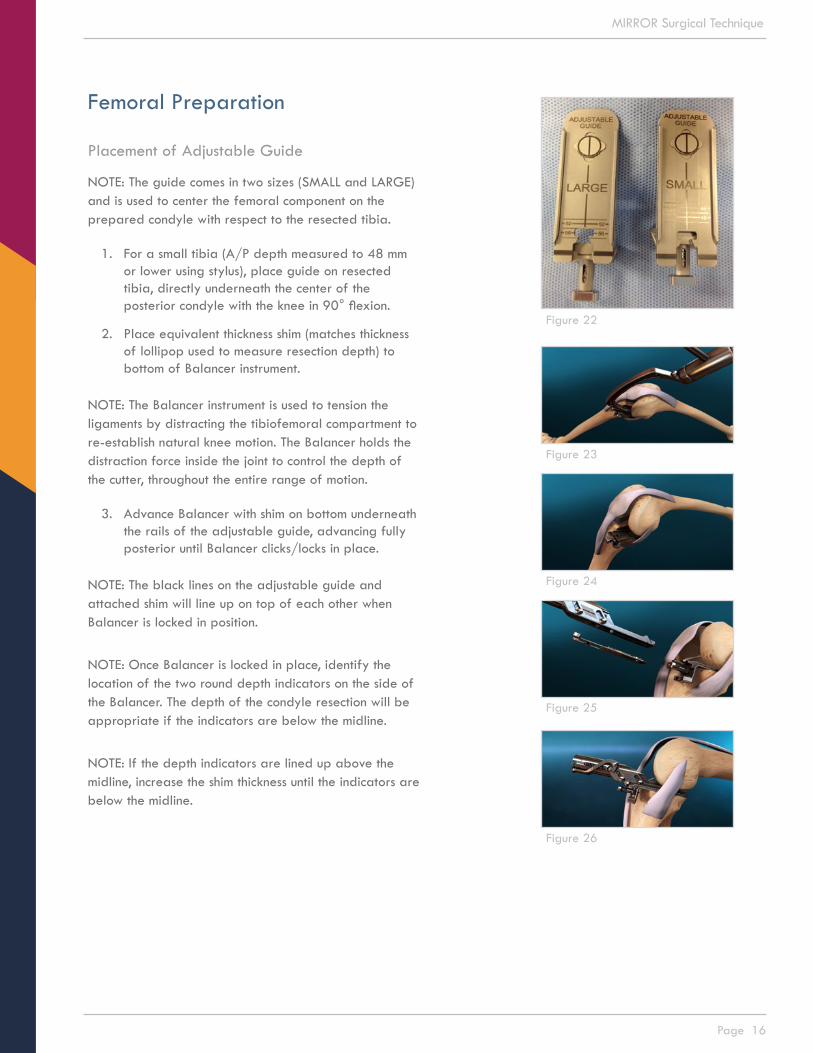
NOTE: The guide comes in two sizes (SMALL and LARGE) and is used to center the femoral component on the prepared condyle with respect to the resected tibia.
1. For a small tibia (A/P depth measured to 48 mm or lower using stylus), place guide on resected tibia, directly underneath the center of the posterior condyle with the knee in 90° flexion.
2. Place equivalent thickness shim (matches thickness of lollipop used to measure resection depth) to bottom of Balancer instrument.
NOTE: The Balancer instrument is used to tension the ligaments by distracting the tibiofemoral compartment to re-establish natural knee motion. The Balancer holds the distraction force inside the joint to control the depth of the cutter, throughout the entire range of motion.
3. Advance Balancer with shim on bottom underneath the rails of the adjustable guide, advancing fully posterior until Balancer clicks/locks in place.
NOTE: The black lines on the adjustable guide and attached shim will line up on top of each other when Balancer is locked in position.
NOTE: Once Balancer is locked in place, identify the location of the two round depth indicators on the side of the Balancer. The depth of the condyle resection will be appropriate if the indicators are below the midline.
NOTE: If the depth indicators are lined up above the midline, increase the shim thickness until the indicators are below the midline.
Figure 23
Figure 24
Figure 25
Figure 26
Figure 22

Page 17
MIRROR Surgical Technique
NOTE: The Positioner is not used to size for the femoral component implant. It is used only to determine position of the femoral component implant on the condyle. The final femoral component implant will be at 90° to the tibial component implant.
Place the Positioner on the Balancer in full apposition to the femoral condyle in flexion. To place the Positioner, flex the knee and slide the blade of the Positioner along the platform under the condyle. The Positioner shows where the femoral component will be placed on the condyle. With the tibia in neutral axial rotation, confirm Positioner location within the margins of the condyle.
4. The Positioner is provided in two configurations; left medial/right lateral and right medial/left lateral. Each configuration has two sizes; SMALL and LARGE.
NOTE: The SMALL Positioner is used with female patients and the LARGE is used with male patients.
NOTE: If the distal medial edge of the Positioner extends beyond the articular margin of the distal condyle, then reposition the adjustable guide on the resected tibia.
NOTE: If both the distal medial and posterior lateral edges of the Positioner overhang respective articular margins, then it is likely that a varus slope in the tibial resection is internally rotating the Positioner and the tibial cut will need to be trimmed closer to 90°.
Figure 27
Figure 28
Figure 29
Figure 30
Page 18
MIRROR Surgical Technique
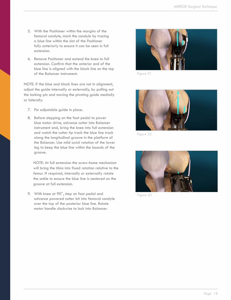
5. With the Positioner within the margins of the femoral condyle, mark the condyle by tracing a blue line within the slot of the Positioner fully anteriorly to ensure it can be seen in full extension.
6. Remove Positioner and extend the knee to full extension. Confirm that the anterior end of the blue line is aligned with the black line on the top of the Balancer instrument.
NOTE: If the blue and black lines are not in alignment, adjust the guide internally or externally, by pulling out the locking pin and moving the pivoting guide medially or laterally.
7. Pin adjustable guide in place.
8. Before stepping on the foot pedal to power blue motor drive, advance cutter into Balancer instrument and, bring the knee into full extension and watch the cutter tip track the blue line track along the longitudinal groove in the platform of the Balancer. Use mild axial rotation of the lower leg to keep the blue line within the bounds of the groove.
NOTE: At full extension the screw-home mechanism will bring the tibia into fixed rotation relative to the femur. If required, internally or externally rotate the ankle to ensure the blue line is centered on the groove at full extension.
9. With knee at 90°, step on foot pedal and advance powered cutter bit into femoral condyle over the top of the posterior blue line. Rotate motor handle clockwise to lock into Balancer.
Figure 31
Figure 32
Figure 33

Page 19
MIRROR Surgical Technique
10. With one hand under the thigh and the other on the ankle, bring the knee into deep flexion, approximately 120° to 125°. Position the tibia in neutral axial rotation and confirm that the blue line is in the plane of the longitudinal groove in the platform. Power the Cutter Drive and advance the cutter through the Balancer and into the condyle. Turn the Cutter Drive to lock it into the Balancer. Bring knee SLOWLY to full extension, with cutter tip tracking on the blue line.
NOTE: Be careful to not hyperextend the knee as this can place the femoral component in a hyperextended position on the condyle. Hyperextension may also artificially collapse the Balancer deepening the Guide Surface and the resulting distal tibiofemoral gap, and place excessive force on the resected tibial plateau that may cause bone fracture.
NOTE: There will be resistance until the cutter advances through the posterior-superior condyle.
NOTE: To keep cutter bit on blue line, you can rotate the ankle externally.
NOTE: While extending the knee, the indicators on the side of the Balancer may move above the midline as the knee extends and the Balancer expands into the distal defect in the condyle. If the Balancer tops out during extension, increase the thickness of the shim and repeat steps 9-10.
11. Remove Balancer instrument by squeezing locking tabs internally while pulling out the Balancer instrument from the adjustable guide.
NOTE: Using a curved curette, clear center groove of any bone or meniscal remnants and ensure the groove extends fully posterior and distal on the femoral condyle.
Figure 34
Figure 35
Figure 36
Figure 37
Figure 38
Figure 39
Page 20
MIRROR Surgical Technique
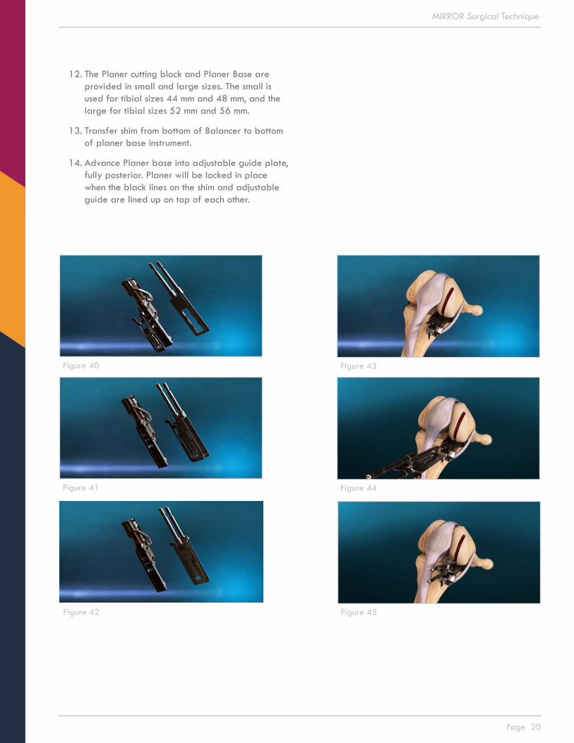
12. The Planer cutting block and Planer Base are provided in small and large sizes. The small is used for tibial sizes 44 mm and 48 mm, and the large for tibial sizes 52 mm and 56 mm.
13. Transfer shim from bottom of Balancer to bottom of planer base instrument.
14. Advance Planer base into adjustable guide plate, fully posterior. Planer will be locked in place when the black lines on the shim and adjustable guide are lined up on top of each other.
Figure 40
Figure 41
Figure 42
Figure 43
Figure 44
Figure 45

Page 21
MIRROR Surgical Technique
15. Starting in deep flexion, power the cutter and advance the Planer with position 1 over the rods of the Base. With one hand behind the knee to support the weight of the leg and the other hand holding the ankle, power the cutter and slowly extend the knee to full extension followed by flexing to deep flexion.
16. Slide the Planer off of the rods and rotate to place position 2 over the rods then advance the Planer then extend and flex the knee with the cutter on. Repeat this for positions 3 and 4.
17. For position 5, with the knee in deep flexion, advance the Planer with positions 1 and 5 over the rods, pull the release knob and sweep the Planer through its full medial/lateral travel two times. Power the cutter, extend the knee and sweep it through its full medial/lateral travel while extending the knee.
Figure 46
Figure 47
Figure 48
Figure 49
Figure 50
Page 22
MIRROR Surgical Technique
Figure 53
Figure 54
Figure 55
Figure 56
Figure 57
Figure 51
Figure 52
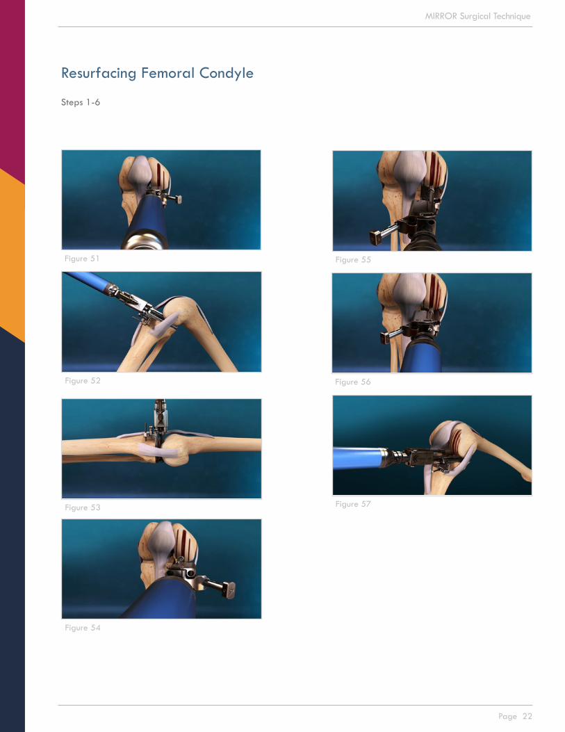
Resurfacing Femoral Condyle
Steps 1-6

Page 23
MIRROR Surgical Technique
Figure 58
Figure 59
Figure 60
Figure 61
Resurfacing Femoral Condyle
Steps 1-6, continued

Page 24
MIRROR Surgical Technique
18. Remove and rotate the Planer to position 6 and repeat the steps taken for position 5.
19. Remove Planer Base using Planer Handle by advancing Handle over rails until the Handle locks in place, which will unlock the Planer Base from the adjustable guide that is pinned on the tibia. Pull back Remover and Planer Base together.
20. Remove pin placed in tibia from the adjustable guide and remove adjustable guide from the tibial plateau.
NOTE: Upon completion of sweep step in position 6, condyle will be fully prepared, with smooth surfaces immediately medial and lateral to the central groove. Many surgeons will irrigate femoral condyle using pulse lavage to remove any cartilaginous and bone debris.
21. Using rongeur, remove any bone ridges left behind after resurfacing steps are complete.
Figure 67
Figure 63
Figure 64
Figure 65
Figure 66
Figure 62

Page 25
MIRROR Surgical Technique
Femoral Implant Sizing
NOTE: The goal is to determine the appropriate femoral component fit for the balanced knee and prepare the condyle for the femoral component. The femoral drill guides come in sizes 38mm, 42mm, 46mm, 50mm and 54mm.
1. Attach the 46mm size Femoral Drill Guide on the handle and place it on the resurfaced condyle. Begin by rocking the guide from posterior to anterior, along the center groove. Impact the Drill Guide.
2. Confirm distal coverage of the condyle and stability from rocking. Confirm direct apposition of the Femoral Drill Guide to the prepared condyle visually along the edges and through the openings in the Guide. Do not choose a size where the guide hangs over the edges of the prepared condyle.
Note: If the initially chosen size 46mm Femoral Drill Guide is stable, the next smaller size should not be attempted. Impacting a smaller Femoral Drill Guide onto the prepared condyle will irreversibly reshape the prepared condyle, preventing use of the larger size due to rocking and instability.
Figure 68
Figure 69
Figure 70
Figure 71

Page 26
MIRROR Surgical Technique
3. Flex the knee to 90° and insert the lollipop (same thickness used after resecting the tibia) underneath the femoral drill guide. Place an Anchor Pin in the hole along the medial side of the Femoral Drill Guide and Pin the guide to the condyle to secure position for drilling the peg holes. Remove the handle to the drill guide.
NOTE: Pin should be inserted and advanced at an angle down and towards the middle of the condyle.
4. Drill the posterior hole on the condyle and insert the peg into that hole before drilling the distal hole.
5. Remove securement pin, lollipop, and drill guide.
Drill or Punch Tibial Holes1. Place the appropriate punch plate with stylus on
the resected tibial plateau to cover the resected surface and cortical margin without overhang. Use stylus confirm coverage of the posterior margin of the prepared tibial plateau.
2. Punch or drill holes in the tibial plateau, going through the posterior hole, followed by punching or drilling the anterior hole.
Figure 72
Figure 73
Figure 74
Figure 75

Page 27
MIRROR Surgical Technique
Implant Trials
NOTE: The goal of this step is to place trial implants to confirm stability and range of motion of the balanced knee.
1. Select the same size implant trial as used for drilling the holes in the condyle. Place the femoral trial onto the prepared condyle using the femoral inserter or free hands. Use femoral impactor to fully seat femoral trial.
2. Select the tibial baseplate trial that corresponds to the size of tibial punch plate used to punch or drill the peg holes in the tibial plateau. Place the tibial baseplate trial on the resected plateau using the tibial inserter or free hands. Use tibial impactor to fully seat baseplate trial on tibial plateau.
3. Place tibial trial into the tibial baseplate using tibial inserter or free hand.
4. Assess stability and range of motion.
Figure 76
Figure 77
Figure 78
Figure 79
Page 28
MIRROR Surgical Technique
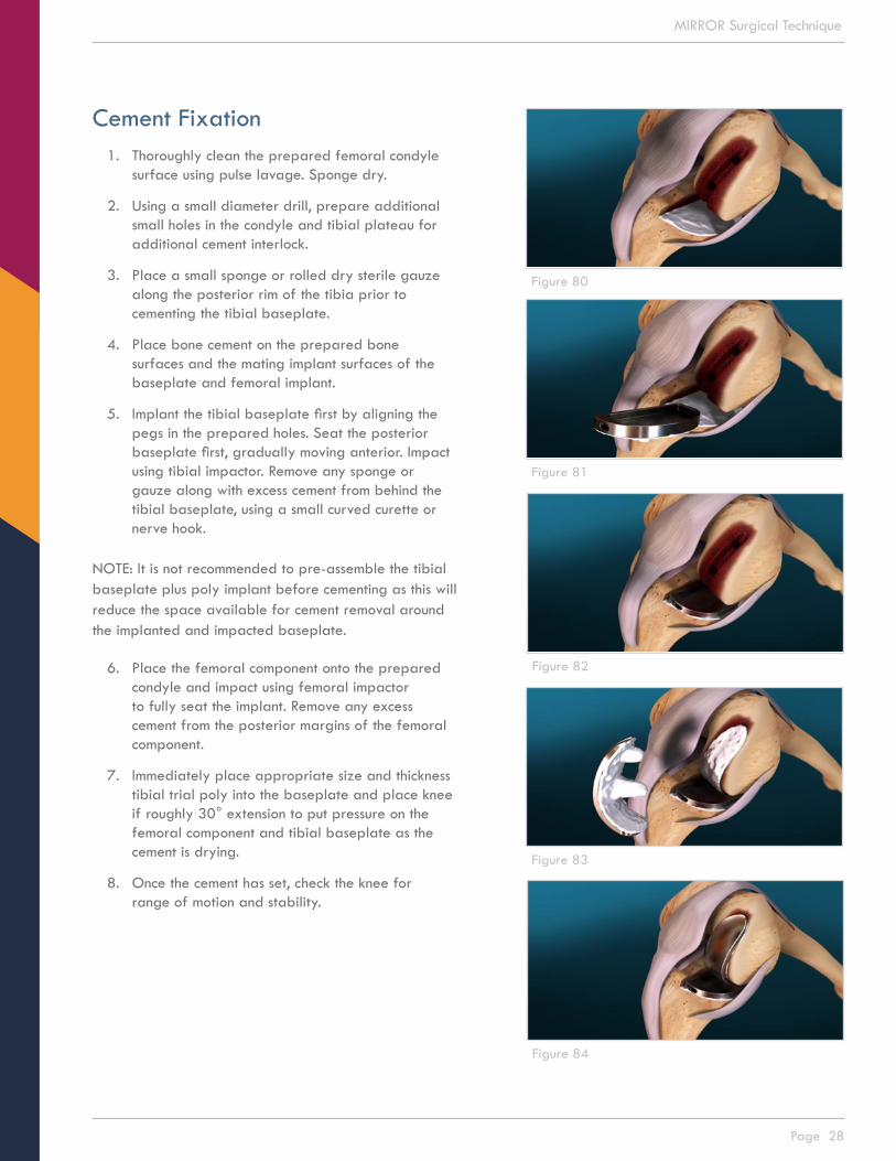
Cement Fixation1. Thoroughly clean the prepared femoral condyle
surface using pulse lavage. Sponge dry.
2. Using a small diameter drill, prepare additional small holes in the condyle and tibial plateau for additional cement interlock.
3. Place a small sponge or rolled dry sterile gauze along the posterior rim of the tibia prior to cementing the tibial baseplate.
4. Place bone cement on the prepared bone surfaces and the mating implant surfaces of the baseplate and femoral implant.
5. Implant the tibial baseplate first by aligning the pegs in the prepared holes. Seat the posterior baseplate first, gradually moving anterior. Impact using tibial impactor. Remove any sponge or gauze along with excess cement from behind the tibial baseplate, using a small curved curette or nerve hook.
NOTE: It is not recommended to pre-assemble the tibial baseplate plus poly implant before cementing as this will reduce the space available for cement removal around the implanted and impacted baseplate.
6. Place the femoral component onto the prepared condyle and impact using femoral impactor to fully seat the implant. Remove any excess cement from the posterior margins of the femoral component.
7. Immediately place appropriate size and thickness tibial trial poly into the baseplate and place knee if roughly 30° extension to put pressure on the femoral component and tibial baseplate as the cement is drying.
8. Once the cement has set, check the knee for range of motion and stability.
Figure 80
Figure 81
Figure 82
Figure 83
Figure 84

Page 29
MIRROR Surgical Technique
9. If satisfied, remove trial poly using tibial inserter and place final poly implant using platypus instrument or free hand.
NOTE: Be absolutely sure that the tibial baseplate is free and clear of any cement or tissue remnants as these will interfere with the placement of the poly.
10. Be sure to orient and seat the posterior end of implant first, gradually seating the anterior portion. It is possible to lightly advance the poly implant into the posterior baseplate using the femoral impactor, placed in a horizontal position, against the anterior end of the implant.
11. Lightly tap once or twice the end of the femoral impactor. Do not use the femoral impactor in the vertical position to seat the poly implant into the baseplate as the locking mechanism may be irreversibly damaged.
12. Perform final irrigation, routine closure and wound management.
Figure 87
Figure 88
Figure 89
Figure 90
Figure 91
Figure 85
Figure 86
Page 30
MIRROR Surgical Technique
Lateral Uni Considerations
Lateral unicompartmental knee replacements have achieved reliable improvements in pain and function and have a high implant survival rate. The outcome of the procedure is largely dependent on appropriate patient selection and surgical technique.
The Mirror system is cleared for use on the lateral side of the knee. The procedure technique steps used for medial knee replacements applies to the lateral side of the knee. Please keep in mind the following considerations when performing lateral unicompartmental knee replacement using the Mirror system:
• Use a lateral peripatellar incision. The lateral edge of the patellar ligament can crowd the entry point for the sagittal cut. Bringing the knee out to 90° or slightly less knee flexion reduces quadricep muscle tension on the patellar ligament easing medial retraction to gain access.
• Be mindful tibial axial rotation when establishing orientation of the sagittal cut. Ensure that the foot is in neutral rotation. Move the proximal tibia anteriorly and posteriorly to sense overall travel of the condyle on the lateral plateau, then position the condyle mid-way of this travel. The medial surface of the intercondylar notch is used as reference for internal/external rotation of the sagittal cut. Pulling the tibia anteriorly or pushing it posteriorly will axially rotate the tibia relative to the condyle which rotates the reference surface for the sagittal cut to external rotation or internal rotation, respectively.
• Make a shallower tibial resection on the lateral side than on the medial side. For example, medial resection depth is typically 4mm whereas typical lateral resection depth maybe 2mm. Use less posterior slope and match the native posterior slope.
• When selecting the preferred femoral component for implant, the anterior margin of the Mirror Femoral Component will appear further back from the tide-mark than what is typical for a medial uni. This is the case as the lateral condyle is longer in A/P than the medial condyle. As for a medial uni, confirm 0° varus/valgus slope of the cut.

Page 31
MIRROR Surgical Technique
Femoral Component Dimensions
Table 1
Figure 92
SIZE ML(MM)
PEG LENGTH
(MM)
DISTALRADIUS
(MM)
POSTERIORRADIUS
(MM)
IMPLANTTHICKNESS
(MM)
38 16 16 38 19 4
42 17.5 16 42 21 4
46 19 18 46 23 4
50 23 20 50 25 4
54 25 22 54 27 4

Page 32
MIRROR Surgical Technique
Table 2
Figure 93
Tibial Baseplate Component Dimensions
SIZE AP(MM)
ML(MM)
H(MM)
44 44 23.5 4.5
48 48 26.5 4.5
52 52 29.5 4.5
56 56 32.5 4.5
Page 33
MIRROR Surgical Technique
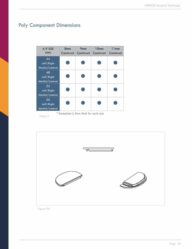
Table 3
Figure 94
Poly Component Dimensions
A/P SIZE(MM)
8mmConstruct
9mmConstruct
10mmConstruct
11mmConstruct
44Left/Right
Medial/Lateral
48Left/Right
Medial/Lateral
52Left/Right
Medial/Lateral
56Left/Right
Medial/Lateral
* Baseplate is 2mm thick for each size

Page 34
MIRROR Surgical Technique
Mirror Instruments
INSTRUMENT SET A (300630A)
300624 Mirror Instrument Tray - A300583 TDG – Base300584 TDG - ARM - 2/4mm300585 TDG - ARM - 3/5mm300586 TDG - Locking Knob300341 TRG - Ankle Clamp300582 TRG - Lower Slide300588 Lower Slide - Knob300575 TRG - Cutting Block – Left300577 TRG - EM Tower - Left300576 TRG - Cutting Block – Right300578 TRG - EM Tower - Right300580 TRG - EM Upper Rod – Long300579 TRG - EM Upper Rod - Short300581 TRG - EM Lower Rod300587 EM Lower Rod - Bottom Knob300120 Anchor Pin300356 Tibial Resection Guide Stylus300122 Pin Puller300617 Tibial Spacer - 8/9mm300618 Tibial Spacer - 10/11mm300620 Alignment Rod300628 Mirror Instrument Tray - Lid
INSTRUMENT SET B (300630B)
300625 Mirror Instrument Tray - B300097 Tibial Press Tool300591 Tibial Punch Plate - Size 44300592 Tibial Punch Plate - Size 48300593 Tibial Punch Plate - Size 52300594 Tibial Punch Plate - Size 56300600 Tibial Punch Plate Gage – Left300601 Tibial Punch Plate Gage – Right300326 Tibia Drill300459 Tibial Punch300104 Cutter300309 Primary Cutter Guard300595 Adjustable Guide - Small300596 Adjustable Guide - Large300527 Positioner - Small Left300529 Positioner - Large Left300528 Positioner - Small Right300530 Positioner - Large Right300103 Balancer300564 TGP - Shim - 8mm300565 TGP - Shim - 9mm300566 TGP - Shim - 10mm300567 TGP - Shim - 11mm300531 Planer Base - Small300532 Planer Base - Large300533 Planer Guide - Small300534 Planer Guide - Large300602 Planer Handle300628 Mirror Instrument Tray - Lid
INSTRUMENT SET C (300630C)
300626 Mirror Instrument Tray - C300488 Femoral Trial - Size 38mm300489 Femoral Trial - Size 42mm300490 Femoral Trial - Size 46mm300491 Femoral Trial - Size 50mm300492 Femoral Trial - Size 54mm300494 Femoral Drill Guide - Size 38mm300495 Femoral Drill Guide - Size 42mm300496 Femoral Drill Guide - Size 46mm300497 Femoral Drill Guide - Size 50mm300498 Femoral Drill Guide - Size 54mm300500 Femoral Drill Guide Handle 300502 Femoral Alignment Pin300501 Femoral Drill300096 Femoral Impactor300429 Modular Tibial Inserter300253 Tibial Inserter300263 Femoral Inserter300384 Tibia - Baseplate Trial - 44L300385 Tibia - Baseplate Trial - 44R300386 Tibia - Baseplate Trial - 48L300387 Tibia - Baseplate Trial - 48R300388 Tibia - Baseplate Trial - 52L300389 Tibia - Baseplate Trial - 52R300390 Tibia - Baseplate Trial - 56L300391 Tibia - Baseplate Trial - 56R300362 Tibia - Insert Trial (44 X 8mm)300363 Tibia - Insert Trial (44 X 9mm)300364 Tibia - Insert Trial (44 X 10mm)300365 Tibia - Insert Trial (44 X 11mm)300366 Tibia - Insert Trial (48 X 8mm)300367 Tibia - Insert Trial (48 X 9mm)300368 Tibia - Insert Trial (48 X 10mm)300369 Tibia - Insert Trial (48 X 11mm)300370 Tibia - Insert Trial (52 X 8mm)300371 Tibia - Insert Trial (52 X 9mm)300372 Tibia - Insert Trial (52 X 10mm)300373 Tibia - Insert Trial (52 X 11mm)300374 Tibia - Insert Trial (56 X 8mm)300375 Tibia - Insert Trial (56 X 9mm)300376 Tibia - Insert Trial (56 X 10mm)300377 Tibia - Insert Trial (56 X 11mm)300628 Mirror Instrument Tray - Lid
OTHER INSTRUMENTS
300108 PDS Controller300355 PDS Foot Pedal300152 PDS Power Cord300107 Cutter Drive

Page 35
MIRROR Surgical Technique
Mirror Implants
FEMORAL IMPLANTS
Catalog # Description 100414 Mirror Two Post Femoral Symmetric, Size 38100415 Mirror Two Post Femoral Symmetric, Size 42100416 Mirror Two Post Femoral Symmetric, Size 46100417 Mirror Two Post Femoral Symmetric, Size 50100418 Mirror Two Post Femoral Symmetric, Size 54
TIBIAL IMPLANTS – Baseplates
Catalog # Description Catalog # Description100294 Mirror Tibial Baseplate w Pegs (LM/RL 44mm) 100295 Mirror Tibial Baseplate w Pegs (RL/LL 44mm)100296 Mirror Tibial Baseplate w Pegs (LM/RL 48mm) 100297 Mirror Tibial Baseplate w Pegs (RL/LL 48mm)100298 Mirror Tibial Baseplate w Pegs (LM/RL 52mm) 100299 Mirror Tibial Baseplate w Pegs (RL/LL 52mm)100300 Mirror Tibial Baseplate w Pegs (LM/RL 56mm) 100301 Mirror Tibial Baseplate w Pegs (RL/LL 56mm)
TIBIAL IMPLANTS – Poly Inserts
Catalog # Description Catalog # Description100312 Mirror Tibial Insert Flat (LM/RL 44x8mm) 100316 Mirror Tibial Insert Flat (RL/LL 44x8mm)100313 Mirror Tibial Insert Flat (LM/RL 44x9mm) 100317 Mirror Tibial Insert Flat (RL/LL 44x9mm)100314 Mirror Tibial Insert Flat (LM/RL 44x10mm) 100318 Mirror Tibial Insert Flat (RL/LL 44x10mm)100315 Mirror Tibial Insert Flat (LM/RL 44x11mm) 100319 Mirror Tibial Insert Flat (RL/LL 44x11mm)
100320 Mirror Tibial Insert Flat (LM/RL 48x8mm) 100324 Mirror Tibial Insert Flat (RL/LL 48x8mm)100321 Mirror Tibial Insert Flat (LM/RL 48x9mm) 100325 Mirror Tibial Insert Flat (RL/LL 48x9mm)100322 Mirror Tibial Insert Flat (LM/RL 48x10mm) 100326 Mirror Tibial Insert Flat (RL/LL 48x10mm)100323 Mirror Tibial Insert Flat (LM/RL 48x11mm) 100327 Mirror Tibial Insert Flat (RL/LL 48x11mm)
100328 Mirror Tibial Insert Flat (LM/RL 52x8mm) 100332 Mirror Tibial Insert Flat (RL/LL 52x8mm)100329 Mirror Tibial Insert Flat (LM/RL 52x9mm) 100333 Mirror Tibial Insert Flat (RL/LL 52x9mm)100330 Mirror Tibial Insert Flat (LM/RL 52x10mm) 100334 Mirror Tibial Insert Flat (RL/LL 52x10mm)100331 Mirror Tibial Insert Flat (LM/RL 52x11mm) 100335 Mirror Tibial Insert Flat (RL/LL 52x11mm)
100336 Mirror Tibial Insert Flat (LM/RL 56x8mm) 100340 Mirror Tibial Insert Flat (RL/LL 56x8mm)100337 Mirror Tibial Insert Flat (LM/RL 56x9mm) 100341 Mirror Tibial Insert Flat (RL/LL 56x9mm)100338 Mirror Tibial Insert Flat (LM/RL 56x10mm) 100342 Mirror Tibial Insert Flat (RL/LL 56x10mm)100339 Mirror Tibial Insert Flat (LM/RL 56x11mm) 100343 Mirror Tibial Insert Flat (RL/LL 56x11mm)
PARTIAL KNEE SYSTEM
Cayenne Medical and MIRROR™ are trademarks of Cayenne Medical, Inc. - A Zimmer Biomet Company 16597 North 92nd St, Suite 101 | Scottsdale, AZ 85260 | cayennemedical.com | 888.229.3661
These products are covered by one or more U.S. patents. © Copyright 2016 Cayenne Medical, Inc. All rights reserved.
This guide is an educational tool and clinical aid to assist properly licensed medical professionals in the usage of specific Cayenne Medical products. The medical professional should rely on their own training and experience and should conduct a thorough review of pertinent medical literature as well as the product’s Instructions For Use.
520-1115-00 Rev MCat. No. 400008