partial discharge detector model pd2u - enertestenertest.cl/pdf/phenix pd2u.pdf · partial...
TRANSCRIPT
Page 1 of 4 Brochure # PD2U, 3/2009
Stand-Alone Instrument
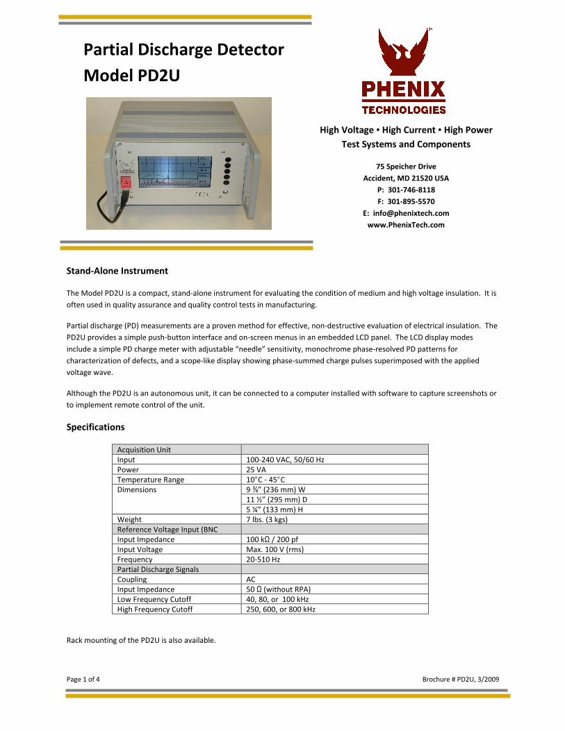
The Model PD2U is a compact, stand-alone instrument for evaluating the condition of medium and high voltage insulation. It is
often used in quality assurance and quality control tests in manufacturing.
Partial discharge (PD) measurements are a proven method for effective, non-destructive evaluation of electrical insulation. The
PD2U provides a simple push-button interface and on-screen menus in an embedded LCD panel. The LCD display modes
include a simple PD charge meter with adjustable “needle” sensitivity, monochrome phase-resolved PD patterns for
characterization of defects, and a scope-like display showing phase-summed charge pulses superimposed with the applied
voltage wave.
Although the PD2U is an autonomous unit, it can be connected to a computer installed with software to capture screenshots or
to implement remote control of the unit.
Specifications
Acquisition Unit
Input 100-240 VAC, 50/60 Hz
Power 25 VA
Temperature Range 10°C - 45°C
Dimensions 9 ⅜” (236 mm) W
11 ½” (295 mm) D
5 ¼” (133 mm) H
Weight 7 lbs. (3 kgs)
Reference Voltage Input (BNC
Input Impedance 100 kΩ / 200 pf
Input Voltage Max. 100 V (rms)
Frequency 20-510 Hz
Partial Discharge Signals
Coupling AC
Input Impedance 50 Ω (without RPA)
Low Frequency Cutoff 40, 80, or 100 kHz
High Frequency Cutoff 250, 600, or 800 kHz
Rack mounting of the PD2U is also available.
High Voltage High Current High Power
Test Systems and Components
75 Speicher Drive
Accident, MD 21520 USA
P: 301-746-8118
F: 301-895-5570
www.PhenixTech.com
Partial Discharge Detector
Model PD2U
Page 2 of 4 Brochure # PD2U, 3/2009
Applications
Instantly displaying information in an intuitive interface, the PD2U is a good choice for applications such as quality control tests
in manufacture of electrical products, and for quality assurance of industrial and utility equipment from capacitors and bushings
to gas-insulated switchgear and others. A wide range of accessories adapts the PD2U to specific testing applications and noise
conditions.
The PD2U equipped with an optional DSO board can be used to locate partial discharge defects in power cable. Using time
domain reflectometry, in which the PD and its “echoes” travel the length of the cable under test, the PD2U provides the
proportional distance of the PD fault along the cable.
The PD2U offers convenient on-site testing of equipment such as cable accessories or sensors installed with gas insulated
switchgear, for instance. Generally, this unit can be used with a full range of preamplifiers, covering the IEC60270 standard and
ultrasonic frequencies up to the UHF range (20 kHz-2 GHz).
To adapt the basic PD2U unit to suit special measurement requirements, it can be equipped with various options:
• Voltage measurement. Adds the HVM oscilloscopic display showing the waveform of the high voltage and calculates
Û, Û/√2, Urms, etc. (standard on PD2U)
• Cable PD location. An additional DSO board samples the PD signal at 100M sample.
• MUX4. Four-channel multiplexer for testing three-phase equipment, such as power transformers. For each channel
the unit maintains an individual set-up and calibration.
• MUX12. With this option a remote 12-channel switching box offers cost-efficient acceptance testing on large power
transformers.
The easy portability, simple operation, and flexibility of the PD2U make it a good choice for routine PD testing in a variety
of utility and industrial applications.
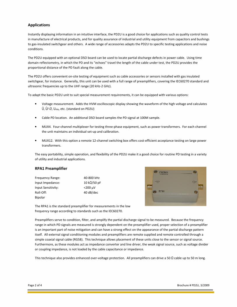
RPA1 Preamplifier
Frequency Range: 40-800 kHz
Input Impedance: 10 kΩ/50 pF
Input Sensitivity: <200 µV
Roll-Off: 40 dB/dec
Bipolar
The RPA1 is the standard preamplifier for measurements in the low
frequency range according to standards such as the IEC60270.
Preamplifiers serve to condition, filter, and amplify the partial discharge signal to be measured. Because the frequency
range in which PD signals are measured is strongly dependent on the preamplifier used, proper selection of a preamplifier
is an important part of noise mitigation and can have a strong effect on the appearance of the partial discharge pattern
itself. All external signal conditioning modules and preamplifiers are remote supplied and remote controlled through a
simple coaxial signal cable (RG58). This technique allows placement of these units close to the sensor or signal source.
Furthermore, as these modules act as impedance converter and line driver, the weak signal source, such as voltage divider
or coupling impedance, is not loaded by the cable capacitance or impedance.
This technique also provides enhanced over-voltage protection. All preamplifiers can drive a 50 Ω cable up to 50 m long.
Page 3 of 4 Brochure # PD2U, 3/2009
Quadrupoles
When a quadrupole and a coupling capacitor are used together as the coupling
device, high voltage is applied both to a test object and to the coupling capacitor
in parallel with the test object. A quadrupole (sometimes called a measuring
impedance) can then be placed in series with either the coupling capacitor or in
series with the test object. Some quadrupoles also output a low-voltage copy of
the applied high-voltage wave for synchronizing the PD detector.
The CIL quadrupoles consist of an inductor in parallel with a damping resistor. The inductor and resistor are calculated to
form, together with a high-voltage coupling capacitor, a second order high pass filter. Therefore, matching the range of
the CIL with the size of the coupling capacitor with which it will be used is important.
The CIL/V quadrupoles are similar to the CIL quadrupoles but also contain a capacitor acting as a voltage divider together
with the high voltage coupling capacitor. This provides a low-voltage copy of the applied high-voltage wave that can be
used through a HST to synchronize the PD detector and monitor the quality of the applied high-voltage wave.
Optionally, the quadrupoles with built-in divider capacitor for voltage measurement can be supplied with a rotary switch
to select the divider capacitor. Especially, when connected to the measurement tap of transformer bushings, the
selectable capacitors expand the applicable voltage range.
CIL4M/V1u00 designed for up to 100 kV, 1 nF Capacitor Range, 400 mA max
CIL4M/V2u00 designed for up to 200 kV, 1 nF Capacitor Range, 400 mA max
CIL4M/V3u50 designed for up to 350 kV, 1 nF Capacitor Range, 400 mA max
Calibrators
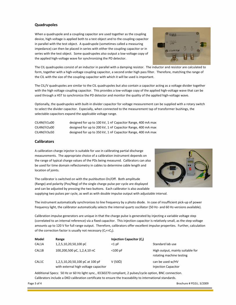
A calibration charge injector is suitable for use in calibrating partial discharge
measurements. The appropriate choice of a calibration instrument depends on
the range of typical charge values of the PDs being measured. Calibrators can also
be used for time domain reflectometry in cables to determine cable length and
location of joints.
The calibrator is switched on with the pushbutton On/Off. Both amplitude
(Range) and polarity (Pos/Neg) of the single charge pulse per cycle are displayed
and can be adjusted by pressing the two buttons. Each calibrator is also available
supplying two pulses per cycle, as well as with double impulse output with adjustable interval.
The instrument automatically synchronizes to line frequency by a photo diode. In case of insufficient pick-up of power
frequency light, the calibrator automatically selects the internal quartz oscillator (50 Hz- and 60 Hz-versions available).
Calibration impulse generators are unique in that the charge pulse is generated by injecting a variable voltage step
(correlated to an internal reference) via a fixed capacitor. This injection capacitor is relatively small, as the step voltage
amounts up to 120 V for full range output. Therefore, calibrators offer excellent impulse properties. Further, calculation
of the correction factor is usually not necessary (CI<<CS).
Model Range Injection Capacitor (CI)
CAL1A 1,2,5,10,20,50,100 pC <1 pF Standard lab use
CAL1B 100,200,500 pC, 1,2,4,10 nC <100 pF High output, mainly suitable for
rotating machine testing
CAL1C 1,2,5,10,20,50,100 pC at 100 pF V (50Ω) can be used w/HV
with external high voltage capacitor Injection Capacitor
Additional Specs: 50 Hz or 60 Hz light sync., IEC60270 compliant, 2 pulses/cycle option, BNC connection.
Calibrators include a DKD calibration certificate to ensure the traceability to international standards.

Page 4 of 4 Brochure # PD2U, 3/2009
75 Speicher Drive
Accident, MD 21520 USA
P: 301-746-8118
F: 301-895-5570
www.PhenixTech.com
High Voltage High Current High Power
Test Systems and Components