part rd-gm-d1 - road design
TRANSCRIPT
Roads
Master Specification
RD-GM-D1 Road Design Document Information
KNet Number: 13555094 Document Version: 3 Document Date: August 2021
Roads Contents
Master Specification 2
Document Amendment Record Version Change Description Date
1 Initial issue 28/06/19 2 Overtaking Lanes added August 2020 3 Re-structured to be a supplement Austroads Guidelines August 2021
Document Management This document is the Property of the Department for Infrastructure and Transport and contains information that is confidential to the Department. It must not be copied or reproduced in any way without the written consent of the Department. This is a controlled document and it will be updated and reissued as approved changes are made.
Roads Contents
Master Specification 3
Contents Contents 3
RD-GM-D1 Road Design 4
1 General 4
2 Objectives of Road Design (AGRD Part 1) 4
3 Network Wide Design (AGRD Part 2) 6
4 Geometric Road Design (AGRD Part 3) 6
5 Intersections and Crossings: General (AGRD Part 4) 12
6 Unsignalised and Signalised Intersections (AGRD Part 4A) 14
7 Roundabouts (AGRD Part 4B) 17
8 Interchanges (AGRD Part 4C) 19
9 Roadside Design, Safety and Barriers (AGRD Part 6) 19
10 New and Emerging Treatments (AGRD Part 7) 20
11 Hold Points and Witness Points 21
Roads RD-GM-D1 Road Design
Master Specification 4
RD-GM-D1 Road Design
1 General
1.1 This Part defines the Requirements for the Design of Roads (excluding tunnels).
1.2 The Austroads Guide to Road Design (AGRD) and Austroads Guide to Traffic Management (AGTM) are the primary technical references adopted for road design by the Department for Infrastructure and Transport (the Department).
1.3 This Master Specification Part has been developed to clarify, or enhance the Austroads Guides and improve consistency of interpretation for State maintained roads in South Australia.
2 Objectives of Road Design (AGRD Part 1)
Jurisdictional Supplements (Section1.6)
2.1 This Master Specification Part is the South Australian jurisdictional supplement to AGRD.
2.2 The Department’s road design standards and guidelines can be located at https://dit.sa.gov.au/standards.
Traffic Control Devices
2.3 The South Australian Commissioner of Highways’ Manual of Legal Responsibilities and Technical Requirements for Traffic Control Devices sets out the mandatory requirements for the use of traffic control devices in South Australia. (reference https://www.dit.sa.gov.au/standards/tass.) It includes:
a) Part 1 – Legal Responsibilities;
b) Part 2 – Code of Technical Requirements.
2.4 The design of traffic control devices is to comply with Australian Standards AS 1742 Parts 1 to 15 and the Department’s Code of Technical Requirements and Operational Instructions that are available at https://www.dit.sa.gov.au/standards/tass.
2.5 The design of all pavement markings will comply with the Department’s Pavement Marking Manual available at https://www.dit.sa.gov.au/standards/tass.
2.6 Where the road design incorporates traffic control devices, (e.g. traffic signs, traffic signals), traffic control devices will comply with the provisions of Master Specification Part RD-LM-D1 “Traffic Control Device Design”.
Maintenance Agreements
2.7 The standard management and maintenance agreements between the Department and Councils is detailed in Operational Instruction 20.1 “Care, Control and Management of Roads by the Commissioner of Highways” available at https://www.dit.sa.gov.au/standards/tass.
Road Design across the Transport Management System (Section 2)
Road Safety Audit (Section 2.2.3)
2.8 Refer to Department’s Master Specification Part RD-GM-02 “Road Safety Audits” for requirements.
Safe System Assessment (SSA) (Section 2.2.3)
2.9 The Department has developed Safe System Assessment (SSA) guidelines which specify when a SSA should be conducted and to provide guidance on the assessment process.
2.10 The Department’s safe system guidelines and templates should be used in conjunction with Austroads “Safe System Assessment Framework”. The Department’s SSA Guideline and Template are available at https://www.dit.sa.gov.au/standards/roads-all.
Roads RD-GM-D1 Road Design
Master Specification 5
2.11 The SSA will be required for all projects. SSAs are recommended and not mandatory for projects under <$2M but require documentation of how the project has considered safe system principles.
2.12 A safe systems assessment is to be completed on all shortlisted options in the project planning phase and subsequently updated through the detailed design development phases.
Principles and Objectives of Road Design (Section 3)
2.13 The Principal has no supplementary requirements for this section.
Road Design Application (Section 4)
Phases of Design (Section 4.2)
2.14 The requirements for “Phase 1 – Establish the Preferred Solution” and Phase 2 – “Further Develop the Solution” are detailed in the Master Specification Parts:
a) PC-PL3 “Concept Design Development”; and
b) PC-PL4 “Constructability Assessments”.
2.15 The requirements Phase 3 – “Detailed Design” are detailed with Master Specification Parts:
a) PC-EMD1 “Engineering and Design Management”;
b) PC-EDM2 “Safety Management in Design”; and
c) PC-EDM3 “Independent Design Certification”.
Normal Design Domain (NDD) (Section 4.4.1)
2.16 The designer is to select parameters within the Normal Design Domain (NDD) to develop value for money designs that manage the inherent risk ‘so far as is reasonably practicable’ whilst providing operational, community and ‘best for the State of South Australia’ outcomes.
2.17 Values within the upper bound and lower bound of NDD (i.e. minimum to desirable) are to be selected based on the road classification, functional hierarchy, location, traffic volumes and topography.
2.18 The road design parameters adopted in the concept design(s) (Phase 1 and 2 – establish the preferred solution) will be reviewed and endorsed by the Department’s Technical Services and constitute a HOLD POINT.
2.19 The selection of design parameters will be documented in the design basis and the design report(s) in accordance with PC-EDM1.
Extended Design Domain (EDD) (Section 4.4.2)
2.20 The use of Extended Design Domain (EDD) parameters is classified as a design exception.
2.21 Values within EDD may be considered on modifications or upgrades to existing roadways in a constrained location or environment.
2.22 The adoption of Extended Design Domain is a HOLD POINT.
Design Exceptions (Section 4.5)
2.23 Design exceptions (including EDD / departures) requires approval by the Engineering Authority for the Commissioner of Highways.
2.24 The Extended Design Domain design departure procedure and form is available at https://dit.sa.gov.au/standards/design_management.
2.25 The acceptance of a Design Exceptions (EDD / Departure) is a HOLD POINT.
Roads RD-GM-D1 Road Design
Master Specification 6
Legal Liability (Section 4.6.1)
2.26 The Principal owes no duty to the Designer to review or examine any of the designer’s calculations, assessments or documents for compliance to the Austroads Guide to Road Design, the Master Specification, Project Requirements or any applicable legislation.
2.27 Notwithstanding any endorsement, approval, acceptance of the design documents or release of Hold Point, by (or on behalf of) the Principal:
a) the designer is not relieved of its legal liabilities; and
b) the Principal has no liability whatsoever to the designer by reason of any errors, deficiencies, defects or omissions in the designer’s documents.
The Road Design Process (Section 4)
2.28 Further information on the requirements are detailed with Master Specification parts:
a) PC-EMD1 “Engineering and Design Management”;
b) PC-EDM2 “Safety Management in Design”; and
c) PC-EDM3 “Independent Design Certification”.
3 Network Wide Design (AGRD Part 2)
3.1 The Department notes Austroads is currently developing an update to AGRD Part 2 to provide guidance on Network Wide Design.
3.2 Prior to its implementation designers are to consider the individual design element in the context of the wider network, location, topography and crash history.
4 Geometric Road Design (AGRD Part 3)
Introduction (Section 1)
4.1 The Principal has no supplementary comments for this section.
Fundamental Considerations (Section 2)
Location (Section 2.2.1)
4.2 The Department has locational classes for each State maintained roads (CBD / inner urban / outer urban / rural). The area class of each road is available on the Department’s Road Asset Information Map and accessible to external designers on request.
4.3 The area class for rural roads through the built-up areas (townships) are to be classified based on adjacent land use (e.g. inner urban or outer urban).
Road Classification (Section 2.2.2)
4.4 The Department has classified the State maintained roads (motorway, arterial, collector and local access) on the DIT intranet (Road Asset Information Map). This information is available to external designers on request.
4.5 The functional hierarchy of state maintained roads within South Australia is included on the Department’s Road Asset Information Map and also included on Location SA (interactive online map http://location.sa.gov.au/viewer/).
4.6 Roads classified as freight routes are nominated in Location SA. http://location.sa.gov.au/viewer/.
Traffic Volume and Composition (Section 2.2.3)
4.7 The traffic volume and composition of State maintained roads within South Australia is included in the Location SA interactive online map http://location.sa.gov.au/viewer/.
Roads RD-GM-D1 Road Design
Master Specification 7
4.8 Further information on existing traffic volumes, composition and turn movements is available on the Department Traffic Intelligence Map and available to external designers on request.
4.9 Traffic modelling is to be completed in accordance with the Master Specification Part RD-GM-D4 “Traffic Analysis and Modelling”.
4.10 The designer is to confirm with the Principal on the future years traffic volumes and composition to be adopted in detailed design.
Design Vehicle (Section 2.2.7)
4.11 The selection of the design vehicle for the roadway will be in accordance with:
a) AGRD Part 4, Section 5.2; and
b) the approved heavy vehicle route networks in South Australia, available on RAVnet, (an interactive online map system http://maps.sa.gov.au/ravnet/.)
4.12 The design vehicle and checking vehicle to be adopted for intersections, is detailed in AGRD Part 4A Section 5 and the supplementary requirements of this Master Specification part.
4.13 The South Australia routes identified as over dimensional routes are available on the internet https://www.sa.gov.au/__data/assets/pdf_file/0010/369082/Freight_class_oversize_overmass_book.pdf .
4.14 The designer shall confirm with the Principal’s Network Management Services (NMS) if the roadway is to accommodate over dimension vehicles in addition to the routes listed above.
4.15 The width allowance for over-dimensional vehicles will include:
a) a clear pavement width of 4.5m for the prime mover and trailer; and
b) full width allowance 900mm above the pavement for the over-dimensional load.
4.16 The design of all roads will enable safe and efficient emergency access for ambulance (SAAS), police (SAPOL), fire (SAMFS / CFS) and emergency (SES) vehicles to adjacent buildings and facilities.
Access Management (Section 2.2.10)
4.17 The designer shall consult with the project team if the roadway is a “controlled-access road”, (restricting access to adjacent properties) or a “local-access road”.
Drainage (Section 2.2.11)
4.18 Road Drainage requirements are documented in Master Specification parts RD-DK-D1 and RD-DK-D2.
Utility Services (Section 2.2.12)
4.19 The designer is to assess and coordinate the road design with Utility Services as detailed in the Master Specification Part PC-US1.
4.20 The location of SA Water and SA Power Network services is included in the Location SA interactive online map http://location.sa.gov.au/viewer/ .
Topography / Geology (Section 2.2.12)
4.21 The Department has terrain classes for each State maintained road (flat / undulating / hilly / mountainous). The terrain class of individual roads is available on the Department Road Asset Information Map and available to external designers on request.
Speed Parameters (Section 3)
4.22 The design speed is to be determined from the 85th percentile speed in accordance with Section 3.2.2 and Commentary 1.
Roads RD-GM-D1 Road Design
Master Specification 8
Inner Urban Roads (Section 3.3)
4.23 The Department has assessed speed profile data from observed traffic counters (from 2010 - 2021) at 32 different sites with a posted speed limit of 60 km/h and 15 sites with a posted speed limit of 50 km/h in the Inner Urban area. Analysis determined a median 85th percentile operational speed of 60.5 km/h and 52 km/h respectively.
4.24 Based on the observed data the Department’s nominal design speed in the inner urban area is to match the posted speed limit.
4.25 The Designer shall review the site specific location and adjacent observed traffic speed data to confirm the adopted design speed based on the 85th percentile operational speed information.
4.26 Information on recorded speed data at the different sites is summarised and available to external parties on request (ref kNet # 12234456).
High Speed - Outer Urban or Rural Roads and Motorways (Section 3.4.1 & 3.4.2)
4.27 Design speed for high speed outer urban or rural roads and motorways is to be in accordance with Section 3.5.2 - New Rural Roads.
4.28 Design speed for existing high standard outer urban and high speed rural roads is to be in accordance with observed 85th percentile operational speed data. When existing data is not available the design speed is to be determined in accordance with Section 3.3.2 and Section 3.4.
Intermediate and Low Speed - Outer Urban and Rural Roads (Sections 3.4.2 & 3.4.3)
4.29 In addition to the description in Section 3.4.3, roads with speed advisory signs on horizontal curves, can be considered as intermediate or low speed roads.
4.30 To ensure consistency, uniformity and driver expectation on the road network, the designer is to determine the 85th percentile operating speed for each element of the low speed road in accordance with either:
a) calculation using the Operating Speed Model as per Section 3.4 and Appendix E; or
b) observed traffic data.
Cross Section (Section 4)
4.31 Selection of cross sections selection will be aligned with the iRAP star rating nominated by the Department for the roadway and road stereotype, in accordance with AP-R619-20, Network Design for Road Safety, Users Guide.
4.32 The selection of cross section elements will make due allowance for over-dimensional vehicles.
Traffic Lane Widths (Section 4.2.4)
4.33 The Department measures lane widths to the “kerb line” as shown in Figure 4.8. This corresponds to the “line of kerb” as shown in Figure 4.20 for different kerb profiles.
Inner Urban Road Widths (Section4.2.5 & 4.4)
4.34 State maintained roads within the inner urban area vary from strategic freight routes to urban connector roads through shopping precincts with high pedestrian activity.
4.35 The selection of road cross sectional elements will be commensurate with the location, pedestrian activity, traffic volumes and vehicle mix and seek to balance the safety risk to all users.
4.36 Provision for cyclist (either on road or off-road facility) are to be included for all inner urban roads.
4.37 For inner urban roads with posted speed limit greater than 60 km/h an off road bicycle facility (shared path or separated bike path) should be provided wherever practicable.
4.38 The nominated freight routes are available on location SA: http://location.sa.gov.au/viewer/.
Roads RD-GM-D1 Road Design
Master Specification 9
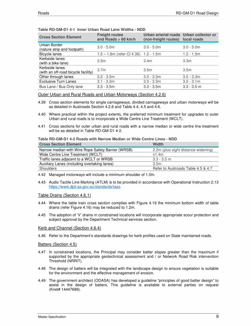
Table RD-GM-D1 4-1 Inner Urban Road Lane Widths - NDD
Cross Section Element Freight routes and Roads > 60 km/h
Urban arterial roads (non-freight routes)
Urban collector or local roads
Urban Border (nature strip and footpath)
3.0 - 5.0m 3.0 - 5.0m 3.0 - 5.0m
Bicycle lanes 1.5 – 1.8m (refer Cl 4.36) 1.2 - 1.5m 1.2 - 1.5m Kerbside lanes (with a bike lane)
3.5m 3.4m 3.3m
Kerbside lanes (with an off-road bicycle facility)
3.7m 3.5m 3.5m
Other through lanes 3.2 - 3.5m 3.0 - 3.3m 3.0 - 3.3m Exclusive Turn Lanes 3.1 - 3.3m 3.0 - 3.3m 3.0 - 3.1m
Bus Lane / Bus Only lane 3.3 - 3.5m 3.3 - 3.5m 3.3 - 3.5 m
Outer Urban and Rural Roads and Urban Motorways (Section 4.2.6)
4.39 Cross section elements for single carriageways, divided carriageways and urban motorways will be as detailed in Austroads Section 4.2.6 and Table 4.4, 4.5 and 4.6.
4.40 Where practical within the project extents, the preferred minimum treatment for upgrades to outer Urban and rural roads is to incorporate a Wide Centre Line Treatment (WCLT).
4.41 Cross sections for outer urban and rural roads with a narrow median or wide centre line treatment will be as detailed in Table RD-GM-D1 4-2.
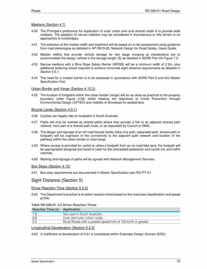
Table RD-GM-D1 4-2 Roads with Narrow Median or Wide Centre Lines - NDD
Cross Section Element Width
Narrow median with Wire Rope Safety Barrier (WRSB) 2.2m (plus sight distance widening) Wide Centre Line Treatment (WCLT) ≤1.4m Traffic lanes adjacent to a WCLT or WRSB 3.3 - 3.5 m Auxiliary Lanes (including overtaking lanes) 3.5m Shoulders Refer to Austroads Table 4.5 & 4.7
4.42 Managed motorways will include a minimum shoulder of 1.0m.
4.43 Audio Tactile Line Marking (ATLM) is to be provided in accordance with Operational Instruction 2.13 https://www.dpti.sa.gov.au/standards/tass.
Table Drains (Section 4.6.1)
4.44 Where the table train cross section complies with Figure 4.19 the minimum bottom width of table drains (refer Figure 4.16) may be reduced to 1.2m.
4.45 The adoption of ‘V’ drains in constrained locations will incorporate appropriate scour protection and subject approval by the Department Technical services section.
Kerb and Channel (Section 4.6.4)
4.46 Refer to the Department’s standards drawings for kerb profiles used on State maintained roads.
Batters (Section 4.5)
4.47 In constrained locations, the Principal may consider batter slopes greater than the maximum if supported by the appropriate geotechnical assessment and / or Network Road Risk intervention Threshold (NRRIT).
4.48 The design of batters will be integrated with the landscape design to ensure vegetation is suitable for the environment and the effective management of erosion.
4.49 The government architect (ODASA) has developed a guideline “principles of good batter design” to assist in the design of batters. This guideline is available to external parties on request (Knet# 14447689).
Roads RD-GM-D1 Road Design
Master Specification 10
Medians (Section 4.7)
4.50 The Principal’s preference for duplication of outer urban and rural arterial roads is to provide wide medians. The adoption of narrow medians may be considered in mountainous or hilly terrain or on approaches to overbridges.
4.51 The selection of the median width and treatment will be based on a risk assessment using guidance from road stereotypes as detailed in AP-R619-20, Network Design for Road Safety, Users Guide.
4.52 Median widths that provide vehicle storage for two stage crossing at intersections are to accommodate the design vehicle in the storage length (S) as detailed in AGRD Part 4A Figure 7.2.
4.53 Narrow medians with a Wire Rope Safety Barrier (WRSB) will be a minimum width of 2.2m, plus additional widening where required to achieve horizontal sight distance requirements as detailed in Section 5.5.1.
4.54 The need for a median barrier is to be assessed in accordance with AGRD Part 6 and this Master Specification Part.
Urban Border and Verge (Section 4.12.3)
4.55 The location of footpaths within the urban border (verge) will be as close as practical to the property boundary (refer Figure 4.58) whilst meeting the objectives of Crime Prevention through Environmental Design (CPTED) and visibility of driveways for pedestrians.
Bicycle Lanes (Section 4.9.1)
4.56 Cyclists can legally ride on footpaths in South Australia.
4.57 Paths will only be marked as shared paths where they provide a link to an adjacent shared path network, form part of a shared path route, or as requested by Council or NMS.
4.58 The design and signage of an off-road bicycle facility (bike only path, separated path, shared path or footpath) will be cognisant of the connectivity to the adjacent path network and location of the pathway within the urban border or road verge.
4.59 Where access is provided for cyclist to utilise a footpath from an on-road bike lane, the footpath will be appropriated designed and sized to cater for the anticipated pedestrian and cyclist mix and traffic volumes.
4.60 Marking and signage of paths will be agreed with Network Management Services.
Bus Stops (Section 4.13)
4.61 Bus stop requirements are documented in Master Specification part RD-PT-D1.
Sight Distance (Section 5)
Driver Reaction Time (Section 5.2.2)
4.62 The Department’s practice is to select reaction times based on the road area classification and speed profile.
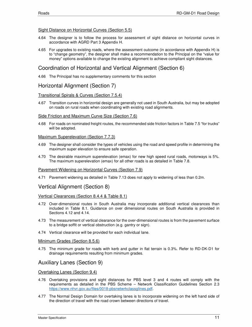
Table RD-GM-D1 4-3 Driver Reaction Times
Reaction Time (s) Application
1.5 Not used in South Australia. 2.0 Inner and outer urban roads. 2.5 Rural Roads with a posted speed limit of 100 km/h or greater.
Longitudinal Deceleration (Section 5.2.3)
4.63 A coefficient of deceleration of 0.61 is considered within Extended Design Domain (EDD).
Roads RD-GM-D1 Road Design
Master Specification 11
Sight Distance on Horizontal Curves (Section 5.5)
4.64 The designer is to follow the process for assessment of sight distance on horizontal curves in accordance with AGRD Part 3 Appendix H.
4.65 For upgrades to existing roads, where the assessment outcome (in accordance with Appendix H) is to “change geometry”, the designer shall make a recommendation to the Principal on the “value for money” options available to change the existing alignment to achieve compliant sight distances.
Coordination of Horizontal and Vertical Alignment (Section 6)
4.66 The Principal has no supplementary comments for this section
Horizontal Alignment (Section 7)
Transitional Spirals & Curves (Section 7.5.4)
4.67 Transition curves in horizontal design are generally not used in South Australia, but may be adopted on roads on rural roads when coordinating with existing road alignments.
Side Friction and Maximum Curve Size (Section 7.6)
4.68 For roads on nominated freight routes, the recommended side friction factors in Table 7.5 “for trucks” will be adopted.
Maximum Superelevation (Section 7.7.3)
4.69 The designer shall consider the types of vehicles using the road and speed profile in determining the maximum super elevation to ensure safe operation.
4.70 The desirable maximum superelevation (emax) for new high speed rural roads, motorways is 5%. The maximum superelevation (emax) for all other roads is as detailed in Table 7.8.
Pavement Widening on Horizontal Curves (Section 7.9)
4.71 Pavement widening as detailed in Table 7.13 does not apply to widening of less than 0.2m.
Vertical Alignment (Section 8)
Vertical Clearances (Section 8.4.4 & Table 8.1)
4.72 Over-dimensional routes in South Australia may incorporate additional vertical clearances than included in Table 8.1. Guidance on over dimensional routes on South Australia is provided in Sections 4.12 and 4.14.
4.73 The measurement of vertical clearance for the over-dimensional routes is from the pavement surface to a bridge soffit or vertical obstruction (e.g. gantry or sign).
4.74 Vertical clearance will be provided for each individual lane.
Minimum Grades (Section 8.5.6)
4.75 The minimum grade for roads with kerb and gutter in flat terrain is 0.3%. Refer to RD-DK-D1 for drainage requirements resulting from minimum grades.
Auxiliary Lanes (Section 9)
Overtaking Lanes (Section 9.4)
4.76 Overtaking provisions and sight distances for PBS level 3 and 4 routes will comply with the requirements as detailed in the PBS Scheme – Network Classification Guidelines Section 2.3 https://www.nhvr.gov.au/files/0018-pbsnetwrkclassglines.pdf.
4.77 The Normal Design Domain for overtaking lanes is to incorporate widening on the left hand side of the direction of travel with the road crown between directions of travel.
Roads RD-GM-D1 Road Design
Master Specification 12
4.78 Overtaking lanes will incorporate a Wide Centre Line Treatment (WCLT) as the minimum treatment between carriageways.
4.79 Merge and diverge tapers for overtaking lanes are to be determined in accordance with Figure 9.4.
4.80 Signs and Pavement marking for overtaking lanes is to be in accordance with Operational Instruction 2.15 https://www.dpti.sa.gov.au/documents/tass.
Rest Areas
4.81 The Department has developed a guideline supplement for rest areas (KNet # 16023127) available on request, which provides guidance on auxiliary lanes for rest areas.
Bridge Considerations (Section 10)
4.82 The Principal has no supplementary comments for this section
5 Intersections and Crossings: General (AGRD Part 4)
Introduction (Section 1)
5.1 The Principal has no supplementary comments for this section.
Types of Intersections (Section 2)
5.2 The Principal has no supplementary comments for this section.
Road Design Considerations for intersections (Section 3)
Road Users (Section 3.1)
5.3 For pedestrian kerb ramps refer to standard drawing S-4074 sheets 6 & 7.
Design Process (Section 4)
Traffic Lanes (Section 4.5.2)
5.4 The Department measures kerb lane widths from the kerb face to the centre of adjacent lane line marking.
Design Vehicles (Section 5)
General (Section 5.1)
5.5 The approved heavy vehicle route networks in South Australia are available on RAVnet (an interactive online map system http://maps.sa.gov.au/ravnet/.)
5.6 The designer is to confirm largest operational vehicle that can make each movement through the intersection (without requiring a vehicle specific permit), based on the nominated RAVnet routes.
5.7 The designer shall confirm with the DIT Network Management Services (NMS) if the intersection movement is to accommodate provision for future increases in the largest Operational Vehicle over the current nominated RAVnet routes.
Design Vehicles (Section 5.2)
5.8 The general design vehicle for intersections will be in accordance with AGRD Part 4, Section 5.2 and Table 5.
5.9 The design vehicle for intersection movements on the National Land Transport Network (NLTN) will be the largest operational vehicle.

Roads RD-GM-D1 Road Design
Master Specification 13
5.10 The design vehicle for turn movements at intersections (excluding NLTN routes) with operational vehicles of a PBS level 2A will be as detailed in Table RD-GM-D1 5-1.
Table RD-GM-D1 5-1 Design and Checking Vehicles
Largest Operational Vehicle Checking Vehicle Design Vehicle
PBS level 1A Refer Section 5.2 and Table 5 PBS Level 2A (PBS) / B-Double (commodity) PBS Level 2A Refer Cl 5.2 & Table 5 PBS Level 2B PBS Level 2B PBS Level 1A PBS Level 3A (PBS) / Road Train (commodity) PBS Level 3A PBS Level 2A PBS Level 3B (PBS) PBS Level 3B PBS Level 2A PBS Level 4A PBS Level 4A PBS Level 3A
5.11 Notwithstanding the requirements in Table RD-GM-D1 5-1, the design will maintain existing vehicular access provisions to existing road and properties.
5.12 Refer to AGRD Part 4, Section 6 and this supplement for public transport design vehicle requirements.
Checking Vehicles (Section 5.3)
5.13 The checking vehicle for turn movements at intersections is to be the largest operational vehicle.
Restricted Access Vehicles (Section 5.4)
5.14 The Department refers to restricted access vehicles as over-dimensional vehicles.
5.15 Guidance on over-dimensional routes on South Australia is provided in Sections 4.12 and 4.14.
Design Vehicle Swept Path (Section 5.6)
5.16 The Department considers the swept path to be the dynamic envelope traversed by the outer extremities of the vehicle body. Mirrors and other devices fitted to vehicle bodies or wheels are assumed to be accommodated in the required minimum swept path offset.
5.17 The designer shall undertake computer analysis (e.g. Autoturn) of the design and check vehicle swept paths and provide sketches of the assessment within the design report.
5.18 The road design will accommodate the design vehicle within marked lanes.
5.19 The application of check vehicle swept path analysis for BAL treatment will be in accordance with Section A 8.2.
5.20 Turn movements for the design vehicle from a single turn lane into a multilane carriageway, may allow the design vehicle to enter the adjacent lane (on the departure side), where the manoeuvre is a legal movement for the Design Vehicle.
Radius of Turn (Section 5.6.2)
5.21 The minimum turning radii used will be not less than the recommended turning radii in AGRD Part 4, Table 5.
5.22 Designer must adopt the following methodology when assessing swept paths:
a) Software parameter “Lock to Lock Time” of 6s must not be altered;
b) Software parameter “Articulation Angel” of 70° (if applicable) must not be altered; and
c) Software supplied vehicles are set to minimum “Kerb to Kerb” radii, these must be altered as per the values in AGRD Part 4 Table 5.1.
Clearance to Swept Paths of Turning Vehicles (Section 5.6.3)
5.23 The design vehicle for turn movements at intersections with more than one turning lane will be determined as follows:
a) Turn lane closest to the kerb – design vehicle:
b) Additional turn lanes – 8.8m service vehicle.
Roads RD-GM-D1 Road Design
Master Specification 14
Public Transport at Intersections (Section 6)
5.24 The design of Public Transport is to comply with the Master Specification Part RD-PT-D1 Bus Operational Guidelines and the Pavement Marking Manual.
Design Vehicle (Section 6.2)
5.25 All intersections on existing or proposed SAPTA bus routes will include a bus in the design vehicle swept path assessment.
5.26 The designer is to confirm with South Australian Public Transport Authority (SAPTA) the bus type to be used in the assessment.
5.27 The Department notes the dimensions of the SAPTA buses vary from Austroads standard turn paths. Information on SAPTA bus dimension are available on request (refer Knet# 1678866).
Bus Facilities (Section 6.3)
5.28 Bus facilities are to be in accordance with the Pavement Marking Manual.
Property Access and Median Openings (Section 7)
5.29 The Principal has no supplementary comments for this section.
Pedestrian Crossings (Section 8)
5.30 Pedestrian crossing facilities are to be provided at all intersections in the inner and outer urban areas.
5.31 Pedestrian crossings are to be in accordance with the Code of Technical Requirements and the Pavement Marking Manual.
5.32 Pedestrian crossings are to comply with the Master Specification Part PR-PF-D1.
Mid-block Crossings on Roads (Section 8.2)
5.33 Refer to DIT standards and Pavement Marking Manual for details on mid-block pedestrian crossings.
Cyclists Crossing (Section 9)
5.34 Cycling crossing facilities (bike lanes or separate paths) are to be provided at all intersections in the inner and outer urban areas.
5.35 Cyclist crossing details are to be in accordance with the Pavement Marking Manual and DIT standard drawings.
5.36 The adoption of a cyclists crossing treatment that has not previous been installed by the Department and / or accepted as a Traffic Control Device by Traffic Engineering and Standards (at Norwood) will be deemed a “New and Emerging Treatment” and subject to a HOLD POINT as per Clause 10.3
Railway Crossing (Section 10)
5.37 The Principal has no supplementary comments for this section.
6 Unsignalised and Signalised Intersections (AGRD Part 4A)
Introduction (Section 1)
6.1 The Principal has no supplementary comments for this section.
Roads RD-GM-D1 Road Design
Master Specification 15
Layout Design Process (Section 2)
Superelevation at or Near Intersections (Section 2.2.4)
6.2 The designer shall undertake a review of superelevation through the turn movements at intersections on freight routes (to reduce the risk of instability for heavy vehicles) in accordance with this clause and AGRD Part 4A Appendix B.
Sight Distance (Section 3)
Safe Intersection Sight Distance (SISD) (Section 3.2.2)
6.3 The Department’s normal practice is to calculate the SISD based on the driver of the vehicle being 3.0m from the stop or give way line.
Pedestrian Crossing Sight Distance Requirements (CSD) (Section 3.3)
6.4 The designer shall assess and document the CSD and the Approach Sight Distance (ASD) for every pedestrian crossing.
6.5 At crossing adjacent to sensitive users (e.g. elderly, vision and mobility impaired, and pedestrians under 12 years old) the average walking speed will be reduced to 1.0 m/s.
Sight Distance at Property Entrances (Section 3.4)
6.6 The designer shall assess sight distances on existing property entrances on State maintained roads.
6.7 Where the existing property access does not currently achieve Extended Design Domain (EDD) SISD (Table A9 to A14), the designer shall assess the movements and crash history at the existing property entrance and recommend to the Principal potential treatments to reduce the inherent risk.
Types of Intersections and their Selection (Section 4)
General (Section 4.1)
6.8 Traffic modelling of intersections will be in accordance with RD-GM-D4 Traffic Analysis & Modelling.
Intersection Types (Section 4.2)
6.9 Network Management Services shall be consulted on the short listed intersection types and function layout in the planning phase of projects.
6.10 Acceptance of the intersection type and function layout for Inner urban and outer urban by Network Management Services (NMS) at the preliminary design phase will constitute a HOLD POINT.
6.11 Warrants for BA, AU and CH turn treatments at outer urban and rural un-signalised intersections will be assessed in accordance AGTM Part 6 Section 3.3.6.
Auxiliary Lanes (Section 5)
6.12 Diverge and merge tapers (excluding overtaking lanes) will be in accordance with AGRD Part 3 Equation 27 and 28 & Table 9.8.
Determination of Deceleration Turn Lane Lengths (Section 5.2.2)
6.13 At interactions located in inner urban area, the Department’s “practical application of this procedure” s to determine the total length of auxiliary lane Figure 5.1 based on the greater value of either:
a) Storage length required for the future year design traffic volumes (S) plus the physical taper Length (T) = (S+T); or
b) Length of deceleration (D) using comfortable deceleration (including Taper length (T)).
Roads RD-GM-D1 Road Design
Master Specification 16
Auxiliary through lanes (Section 5.5)
6.14 The length of auxiliary through lanes on approach will be based on the volume of traffic that can be discharged within a traffic signal green signal plus the taper.
6.15 The length of auxiliary through lanes on approach departure will be determined by 4 sec of travel time at the 85th percentile operational speed, plus the taper.
Traffic Island and Medians (Section 6)
Raised High Entry Left Turns and Free Flow left turn islands (Section 6.1.3)
6.16 Raised High Entry Left Turn Treatments (HELT) at signalised intersections are to be in accordance with DIT standard drawings S-4076 sheets 1 & 2, (replacing Figure 6.3, 6.4 and 6.5).
6.17 Free flow left turn islands (ref Figure 6.7 and 6.9) will include a provision for cyclist to travel across the island and cross the acceleration lane at 90 degree as per AGRD Part 4 Figure A14 and the Pavement Marking Manual.
Painted Medians (Section 6.2)
6.18 Painted medians will be in accordance with the Pavement Marking Manual https://www.dpti.sa.gov.au/documents/tass.
Right-turn Treatments (Section 7)
Rural Right-turn Treatments (Section 7.3)
6.19 Rural seagulls will be in accordance with AGRD Part 4 Section A.7.5, Figure A11 or A12, with an acceleration length determined for passenger cars from the hold line.
6.20 Hold lines (give way and stop) will be located within 3.0m of the through lane and as per the Pavement Marking Manual unless agreed otherwise by Traffic Assess Standards.
Left –Turn Treatments (Section 8)
6.21 The designer shall refer to AGTM Part 6 for guidance on the selection of left turn treatment (e.g. kerb return, HELT or free-flow left turn). Selection of the treatment will be based on site specific features and risks, cognisant of:
a) pedestrian demand, adjacent sensitive users and potential for crowding;
b) sight distances;
c) cyclist facilities; and
d) traffic operational benefit.
6.22 High Entry Left Turn Treatments (HELT) are to be in accordance with the DIT Pavement Marking Manual and Standard Drawings S-4076 sheets 1 & 2.
6.23 Provision for cyclists at left-turn treatments will be in accordance with AGRD Part 4 Section A.8.
Signalised intersections (Section 9)
6.24 In addition to AGRD Part 4A, Austroads provides further guidance on the design of signalised intersections in AGRD Part 4 Appendix B.
Traffic Lanes (AGRD Part 4 Section B.4)
6.25 A minimum of two lanes will be provided at all signalised intersection approaches. A left turn slip lane can be counted as one lane of the two lanes.
6.26 The Department’s preferred practice is to avoid shared lanes (through and turn) at intersections.
Roads RD-GM-D1 Road Design
Master Specification 17
Pedestrian Treatments (AGRD Part 4 Section B.5)
6.27 Pedestrian crossing facilities will be provided at all signalised intersections.
Pedestrian Facilities – Mid Block (AGRD Part 4 Section B.5)
6.28 Mid-block pedestrian (or cyclists) crossing facilities will be in accordance with the DIT Pavement Marking Manual and Standard Drawings.
6.29 Pedestrian crossings are to comply with the Master Specification Part PR-PF-D1.
Cyclist Facilities at Signalised Intersections (AGRD Part 4 Section B.6)
6.30 Cyclist facilities will be provided at all signalised intersections.
6.31 Cyclist facilities will be in accordance with the DIT Pavement Marking Manual.
6.32 The Department does not support the use of right-turn bicycle facilities that require cyclist to weave across traffic to continue their journey (e.g. Figure B10-4 waiting (a) and Figure B12-example a & c).
6.33 The Department does not support the use of left-turn bypass bicycle treatments as detailed in Figure B14.
7 Roundabouts (AGRD Part 4B)
Introduction (Section 1)
7.1 The Principal has no supplementary comments for this section.
Design Principles and Procedures (Section 2)
7.2 The Principal has no supplementary comments for this section.
Sight Distances (Section 3)
7.3 The Principal has no supplementary comments for this section.
Geometric Design (Section 4)
Central Island Radius (Section 4.4.3)
7.4 In addition to the requirements in AustRoads, the initial selection of the central island radius for four leg roundabouts on State maintained roads will be increased based on the largest operational vehicle as detailed in Table RD-GM-D1 7-1.
Table RD-GM-D1 7-1 Recommended Central Island Radii
Largest Operational Vehicle Single Lane Roundabout Dual Lane Roundabout (on at least who approaches)
PBS Level 1A Refer Section 4 and Table 4.1 Refer Section 4 and Table 4.1 PBS Level 2A Refer Section 4 and Table 4.1 Refer Section 4 and Table 4.1 PBS Level 2B 14m min 15 – 25m des 18m min 19 – 30m des PBS Level 3A & 3B 20m min 21 – 30m des 26m min 27 – 35m des PBS Level 4A 26m min 27 – 35m des 30 m min 31 – 40m des
Approach and Entry Treatments - Approach Treatments for High Speed Areas (Section 4.5.2)
7.5 Reverse curves may be adopted on approach for roundabouts with a posted speed limit greater than 80 km/h prior to the roundabout approach, to encourage drivers to reduce their speed prior to entering the roundabout.
7.6 Where reverse curves are adopted a short straight is to be provided to transition superelevation between the curves to reduce the risk of instability to High Centre of Gravity (HCoG) vehicles.
Roads RD-GM-D1 Road Design
Master Specification 18
7.7 In constrained locations where reverse curves are not suitable, two or more “approach treatments” as detailed in Section 4.5.2 may be adopted.
Maximum Entry Path Radius (Section 4.5.3)
7.8 Where the circulating carriageway is wider than 5.0m the determination of the entry path radii as detailed in Figures 4.5 and 4.6 will be based on a maximum value of 2.5m for M2.
Circulating Carriageway (Section 4.6.2)
7.9 Circulating carriageway width for single lane roundabouts should be limited to 7.0m.
7.10 For two or more lane roundabouts, individual lane widths should be limited to 5.5m maximum.
7.11 Where additional width is required for turning movements of heavy vehicles, consideration should be given to providing encroachment areas or larger central islands to achieve the maximum lane widths.
Encroachment areas (Section 4.6.3)
7.12 Figure 4.11, Type A encroachment areas will be adopted on State maintained roads.
7.13 Encroachment areas may be used on the kerb side to maintain roundabout entry curvature, whilst still enabling access by the largest operational vehicle. Where kerbside encroachment is adopted pedestrian crossing facilities will be offset a minimum of 2.0m from encroachment areas.
Superelevation, Gradient and Drainage (Section 4.10)
7.14 The Department’s normal practice is to provide adverse crossfall through the roundabout circulating carriageway.
7.15 Subject to achieving drainage requirements, adverse crossfall of 2% on single lane roundabouts and 2.5% on multi-lane roundabout may be adopted to reduce the risk of truck instability.
7.16 Rates of rotation for superelevation as the vehicle travels through the roundabout should not exceed the maximum.
7.17 Designers need to ensure the design of roundabout does not cause instability issues for heavy vehicles including (HCoG) vehicles.
7.18 Roundabouts should be assessed to review the risk of instability:
a) using simulation software (e.g.,TruckSim, HVE or UM Truck):
i) on nominated freight routes; or
ii) turn movements with the largest operational vehicle of a PBS 2A or greater; and
b) as per AGRD Part 4A Appendix B - for on all other turn movements.
7.19 For further guidance on vehicle stability assessment, the designer may refer Main Roads WA, “Guidelines for Vehicle Stability Analysis – Main Roads Internal Process” guidelines-for-vehicle-stability-analysis-internal-main-roads-process.pdf
Pedestrian and Cyclist Treatments (Section 5)
7.20 Bicycle lane treatments at Roundabouts will be in accordance with the Pavement Marking Manal.
7.21 Multilane roundabouts will include an alternate off road pathway for cyclists to navigate the roundabout in accordance with the Pavement Marking Manal and AGRD Figure 5.4.
Pavement marking and signs (Section 6)
7.22 Pavement marking and signage will be in accordance with the Pavement Marking Manual.
Roads RD-GM-D1 Road Design
Master Specification 19
Landscaping and Street Furniture (Section 7)
Maintenance (Section 7.4)
7.23 Maintenance access provisions for people and or vehicles to access landscaping, street furniture (including lighting) within the roundabout will be agreed with the Department’s maintenance personnel.
8 Interchanges (AGRD Part 4C)
Types of Structures (Section 4.1.1)
8.1 The Department’s normal practice is to provide “spill through” abutments consistent in aesthetics with other adjacent projects.
8.2 The designer is to review the project specific urban design framework to coordinate the type of structure with the desired project amenity.
Safety Screens (Section 4.9)
8.3 Further information on the requirements are detailed with Master Specification part ST-SD-D1.
Ramp Terminal at Minor Road (Section 8.3.4)
8.4 The Department’s normal practice is to install either a roundabout or signalised intersection at service interchange ramp terminals with minor roads.
Exit Ramp (Section 11.2)
8.5 Excluding motorways, single lane exit ramps as detailed in figure 11.1(b) may be adopted for exit ramps with lower traffic volumes.
8.6 Comfortable deceleration for cars (0.26) will be adopted for deceleration distance (Dd) at exit ramps.
Entry Ramps (Section 11.3)
8.7 The use of simple merge as detailed in Figure 11.6 is not considered within Normal Design Domain.
9 Roadside Design, Safety and Barriers (AGRD Part 6)
Methodology
9.1 Austroads update to AGRD Part 6 (2020), includes a new approach to consider a project as part of the wider road network to provide best road corridor safety outcomes.
9.2 The Department supports the adoption of AGRD Part 6 (2020).
9.3 The AGRD Part 6 (2020) methodology will be adopted for projects within the following criteria:
a) rural areas 1km or greater;
b) inner and outer urban areas 500m or greater; and
c) roadway is in flat or rolling terrain.
9.4 Projects that do not meet the above criterial will be assessed using the AGRD Part 6 (2010) previous methodology.
Roads RD-GM-D1 Road Design
Master Specification 20
Introduction (Section 1)
Roadside Safety Design (Section 1.6)
9.5 Irrespective of the guideline or methodology adopted (AGRD Part 6 -2020 or 2010) the designer shall always use their “Engineering Judgement” to reduce the residual risk to road users “so far as is reasonably practicable” through designing a road network that:
a) reduces the probability a driver loses control of a vehicle;
b) reduces the probability a road user (pedestrian, cyclist or driver) miscalculates a movement at a crossing or intersection;
c) remove or reduces (where practical) the hazards in the road environment; and
d) minimises the severity of any crash that may occur to all road users.
Network Risk Assessment (Section 2)
General (Section 2.1)
9.6 The use of Network Roadside Risk Intervention Threshold (NRRIT) is a new methodology to the Department, and its adoption threshold levels are still under development.
Network Roadside Risk Intervention Threshold (NRRIT) (Section 2.4)
9.7 The NRRIT should be determined in the planning phase for each individual project, based on the targeted iRAP star rating proposed for the corridor.
9.8 The NRRIT for new road corridor “greenfield” sites is to be as low as possible within economic constraints, with a nominal NRRIT of 1.0 initially recommended as a target level.
9.9 The NRRIT initially recommended as a target level for modifications, changes or upgrades to existing roadways is as detailed in Table RD-GM-D1 9-1.
Table RD-GM-D1 9-1 Nominal NRRIT, upgrades to existing roads
Location Classification Nominal NRRIT
Rural road Arterial / Highway 1.25 Collector 1.5
Inner or outer Urban road speed limit > 60 km/h Arterial or Collector 1.5
Inner or outer urban roads speed limit ≤ 60 km/h Arterial / Highway 1.5 Collector and local 1.75
9.10 The selection of the corridor and projects NRRIT target score rating will be agreed with the Principal prior to commencing detailed design.
9.11 The determination of the NRRIT will constitute a HOLD POINT.
9.12 The Department has created a risk score calculation spreadsheet which is based on AGRD Part 6 (2020). Refer to https://www.dpti.sa.gov.au/standards/road_design_outputs.
Risk Evaluation Procedure (Appendix B)
9.13 Oncoming vehicle risk for a divided road or road with a Wide Centre Line Treatment (WCLT) is calculated by assuming the oncoming vehicle is an isolated hazard with a lateral distance to the isolated hazard of the median or WCLT width plus a 0.5m allowance for vehicle located within the lane.
10 New and Emerging Treatments (AGRD Part 7)
10.1 The Department supports the consideration and appropriate of new and emerging treatments included in AGRD Part 7 for treatments on State maintained roads.
10.2 The adoption of new or emerging treatment in the short list of options within the project planning phase or as part of detailed design development will be subject to approval of:
Roads RD-GM-D1 Road Design
Master Specification 21
a) Network Management Services (NMS) – Traffic Control Devices; and
b) Technical Services Section – Extended Design Domain / Departures.
10.3 The adoption of new or emerging treatments will constitute a HOLD POINT.
11 Hold Points and Witness Points
11.1 The following is a summary of Hold Points referenced in this Part:
Clause HOLD POINT Response Time
2.19 Road design parameters adopted in planning phase 5 days 2.22 The adoption of Extended Design Domain 5 days 2.25 Endorsement of Design Exceptions (EDD / Departures) 10 days 6.10 Acceptance of the intersection type and function layout by NMS 10 days 9.10 Selection of NRRIT prior to commencing detailed design 10 days 10.3 Adoption of new or emerging treatments 10 days