part number configurator - fortress interlocks part number... · head + actuator combined part...
TRANSCRIPT

Integrated Control & Safety
tGar
dPa
rt N
umbe
r Con
figur
ator

An Innovative Platform for Machine Safety
tGard is the new innovative approach to controlling access to hazardous machinery and equipment. It is a compact metal bodied system that enables the configuration of various safety products including electrical safety gate switches (with or without guard locking), mechanical trapped key interlocks, and electrical operator controls, either as separate devices or integrated into one device.tGard offers “a customised safety solution, as standard” and is defined by a range of tGard elements, including selector switches, safety switches (solenoid and non solenoid), personnel keys, emergency release, push buttons, estops, indicator lamps and a choice of operating handles for both hinged and sliding guard doors. These elements are simply selected and then assembled into a robust housing, suitable for mounting onto machine guarding, providing the user with an exact configuration specific to the application.tGard is quick and easy to install and can be mounted directly onto a flat surface, doors or extruded aluminium profiles without the need for mounting plates or brackets. It is IP65 as standard and has been designed to be fully compliant with the new machinery safety standards.
Customised Safety Solutions as Standard
• Simply Robust• Customisable• Future proof for future element expansion• Easy to Install• Quick Disconnects as standard
• Standards compliant• Trailing Cables as standard• Safety Gate Switches• Trapped Key Interlocks• Operator Control
Handle Actuator featuring an optional internal door knob
Internal Release functionSafety and Access Lock Elements
Safety Switch Elements
Push Button - Illuminating and Non illuminating elements.LED LampsSelector Switches Illuminating and Non illuminating 2 Position & 3 Position
Selector Key Switch - 2 position.
tGard Bodies, available in different element lengths.
1,2,3,4,5,6,8 & 10
Solenoid Element for automatic locking
Quick Disconnects orTrailing Cables as standard

TAF TAH TAS THB TEN TEH
Part No. TAF Part No. TAH Part No. TAS Part No. THB Part No. TEN Part No. TEH Description Fixed Actuator Description Handle
Actuator - Hinged Door
Description Handle Actuator - Sliding Door
Description Blank Handle Description Handle Actuator - (no internal knob)
Description Handle Actuator
Features & Benefits Features & Benefits Features & Benefits Features & Benefits Features & Benefits Features & Benefits
• Fixed Actuator suitable for mounting on either sliding or hinged doors.
• Padlock through tongue.
• 2500N Retention force.
• Handle actuators suitable for bracketless mounting to hinged doors.
• 4mm misalignment feature. • TAH actuator can be converted to a TAS actuator on site (special tool required).
• Padlock through tongue.
• 2500N Retention force.
• Quick bolt to Aluminium extrude (no brackets).
• Handle actuators suitable for bracketless mounting to sliding doors. • 4mm misalignment feature.
• TAS actuator can be converted to a TAH actuator on site (special tool required).
• Padlock through tongue.
• 2500N Retention force.
• Quick bolt to Aluminium extrude (no brackets).
• Blank Handle (without actuator) for use on inside of doors.
• Intuitive handle actuator giving latching feature on hinged doors.
• 4mm misalignment feature.
• Lock out feature.
• Handing can be changed on site.
• Prevents force of door slamming against interlock.
• 2500N Retention force.
• Quick bolt to Aluminium extrude.
• Intuitive handle actuator giving latching feature on hinged doors.
• 4mm misalignment feature.
• Lock out feature.
• Handing can be changed on site.
• Prevents force of door slamming against interlock.
• 2500N Retention force.
• Quick bolt to Aluminium extrude.
• Internal knob allows actuator to be retracted but not extended.
Step 1: Choose the ActuatorsA
ctua
tors
iNote: The internal
knob on TEH handle does not override the
solenoid or lock. A TRX/Z (internal release element) must be used to deliver
that functionality.
All Actuators to be used in combination
with a THM head module.
tit

Step 2: Head ModulesH
ead
Mod
ules
THC THM
Part No. THC Part No. THMDescription Cap Element Description Actuator Head Element
Features & Benefits Features & Benefits
• Used to terminate all non door lock or gate switch configurations.
• Used in mechanical exchange box, machine control or key switch configurations.
• Ideally suited for authorised access only, or linked access to other machinery.
• 5 orientations (left, right, front, back and top).
• Can be used to lock door when used with keys or solenoid or just as driver for safety switches.
• Rotatable through 90º (remove screws).
• 2500N retention force.
• Metal construction with no extra fixing required.
Head + Actuator Combined Part Number OptionsTHF THH THS THE THN
Part No. THM + TAF = THF Part No. THM + TAH = THH Part No. THM + TAS = THS Part No. THM + TEH = THE Part No. THM + TEN = THN Description Head module
including fixed actuator
Description Head module including hinged actuator
Description Head module including sliding actuator
Description Head module including handle actuator
Description Head module including handle actuator (no internal knob)
iYou can combine a
actuator with a head to generate a single part
number
t

Step 3: Internal Release C
ore
Ele
men
ts
Extended version available
(TRZ) - any length possible
i
TRX TRZ
Part No. TRX Part No. TRZDescription Standard 60mm
Internal ReleaseDescription Variable length
Internal Release
Features & Benefits
• Element allows emergency exit even if unit is locked by keys and or solenoid.
• Unit automatically breaks safety circuits and holds them open until unit is reset.
• When present, the push IR always occupies the top element.
• TRX works through wall thickness upto 60mm.
• TRZ allows customer to customise length of emergency release.
• Post should be supported if not going through aluminum extrude.
t
Step 4: Safety & Access Lock Element
i
All keys need to be ordered separately
Cor
e E
lem
ents
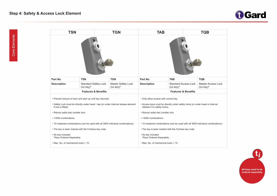
TSN TGN TAB TQB
Part No. TSN TGN Part No. TAB TQB Description Standard Safety Lock
(no key)* Master Safety Lock (no key)*
Description Standard Access Lock (no key)*
Master Access Lock (no key)*
Features & Benefits Features & Benefits
• Prevent closure of door and start up until key returned.
• Safety Lock must be directly under head / cap (or under internal release element if one is fitted).
• Robust radial disc tumbler lock.
• >3000 combinations.
• 10 mastered combinations (can be used with all 3000 individual combinations).
• The key is laser marked with the Fortress key code.
• No key included. *Keys Ordered Separately.
• Max. No. of mechanical locks = 10.
• Only allow access with correct key.
• Access keys must be directly under safety locks (or under head or internal release if no safety locks).
• Robust radial disc tumbler lock.
• >3000 combinations.
• 10 mastered combinations (can be used with all 3000 individual combinations).
• The key is laser marked with the Fortress key code.
• No key included. *Keys Ordered Separately.
• Max. No. of mechanical locks = 10.
t

Step 5: Safety Switches C
ore
Ele
men
ts
TSM / TSP TSS
Part No. TSM / TSP Part No. TSSDescription Safety Switch Description Safety Switch - No N/O monitor contact
Features & Benefits Features & Benefits
• Can be driven by either the operation of the head element (removal of actuator) or a mechanical lock.
• Operates on dual safety circuits.
• 2 positively driven force break NC contacts (uses none of the I/O pins).
• IP65.
• 1 Normally Open (N/O) contact giving 24V signal on I/O pin.
• Red LED illumination to show door open.
• First element after all mechanical elements (Head, Internal Release and Locks).
• Extra retention force available (TSP).
• Can be driven by either the operation of the head element (removal of actuator) or a mechanical lock.
• Operates on dual safety circuits.
• 2 positively driven force break NC contacts (uses none of the I/O pins).
• IP65.
• First element after all mechanical elements (Head, Internal Release and Locks).
• No monitor contact & no LED.
• Uses 4 pins for safety circuits (no power required). *Works with TQ1 (5 Pin QD).
Number of Safety Circuits 2 Number of Safety Circuits 2
Number of Control I/O 1 Number of Control I/O 0
iLocation of
safety switch in stack is first element after all mechanical
elements (Head, Internal Release
and Locks).
t

Step 6: Solenoid Controlled Lock & Safety Switch Elements - Power to Un-Lock / Power to Lock C
ore
Ele
men
ts
Power to Un-lock Power to Lock • 1 input used to energise solenoid.
• Power to Lock and Power to Unlock options available.
• Solenoid override key provided with power to unlock units.
• First element after all mechanical elements (Head, Internal Release and Locks).
iLocation of
safety switch in stack is first element after all mechanical
elements (Head, Internal Release
and Locks).
t
i
90% of customers select TSMDU
t
TSMDU/L TSMEU/L TSMFU/L TSSEU/L
Part No. TSMDU / TSMDL TSMEU / TSMEL TSMFU / TSMFL TSSEU / TSSELDescription Head & solenoid safety in series
TSMDU (Power to Un-lock)
TSMDL (Power to Lock)
Safety on head element only
TSMEU (Power to Un-lock)
TSMEL (Power to Lock)
Four safety circuits
TSMFU (Power to Un-lock)
TSMFL (Power to Lock)
Safety on head element only (no monitoring contact on head)
TSSEU (Power to Un-lock)
TSSEL (Power to Lock)
Features & Benefits • 2500N retention force.
• 2 X Normally closed safety circuits run through head safety switches and solenoid safety switches.
• Non safety monitor circuit on head gives 24V when door opened.
• Non safety monitor circuit on solenoid gives 24V when unlocked.
• LED sequence: *Green = Door closed & locked *Green & Red = Door closed but unlocked *Red = Door open
• 2500N retention force.
• 2 X Normally closed safety contacts driven by head only (not solenoid).
• Non safety monitor circuit on head gives 24V when door opened.
• Non safety monitor circuit on solenoid gives 24V when locked.
• LED sequence: *Green = Door closed & locked *Green & Red = Door closed but unlocked *Red = Door open
• 2500N retention force.
• Four safety circuits - 2 independent NC circuits for the head and 2 independent NC circuits for the solenoid.
• Non safety monitor circuit on head gives 24V when door opened.
• Non safety monitor circuit on solenoid gives 24V when unlocked.
• LED sequence: *Green = Door closed & locked *Green & Red = Door closed but unlocked *Red = Door open
• 2500N retention force.
• 2 X Normally closed safety contacts driven by head only (not solenoid).
• Non safety monitor circuit on solenoid gives 24V when locked.
• LED sequence: *Nothing = Door closed & locked *Red = Door unlocked
Number of Safety Circuits 2 2 4 2
Number of Control I/O 3 3 3 2
Step 7: Emergency Stop Element C
ore
Ele
men
ts
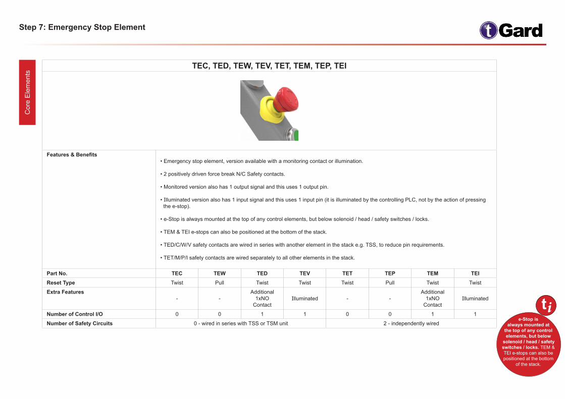
TEC, TED, TEW, TEV, TET, TEM, TEP, TEI
Features & Benefits • Emergency stop element, version available with a monitoring contact or illumination.
• 2 positively driven force break N/C Safety contacts.
• Monitored version also has 1 output signal and this uses 1 output pin.
• Illuminated version also has 1 input signal and this uses 1 input pin (it is illuminated by the controlling PLC, not by the action of pressing the e-stop).
• e-Stop is always mounted at the top of any control elements, but below solenoid / head / safety switches / locks.
• TEM & TEI e-stops can also be positioned at the bottom of the stack.
• TED/C/W/V safety contacts are wired in series with another element in the stack e.g. TSS, to reduce pin requirements.
• TET/M/P/I safety contacts are wired separately to all other elements in the stack.
Part No. TEC TEW TED TEV TET TEP TEM TEIReset Type Twist Pull Twist Twist Twist Pull Twist Twist
Extra Features - -
Additional 1xNO
Contact Illuminated - -
Additional 1xNO
ContactIlluminated
Number of Control I/O 0 0 1 1 0 0 1 1
Number of Safety Circuits 0 - wired in series with TSS or TSM unit 2 - independently wired
ie-Stop is
always mounted at the top of any control elements, but below
solenoid / head / safety switches / locks. TEM & TEI e-stops can also be positioned at the bottom
of the stack.
t
Step 8: Start Re-Start Switch C
ore
Ele
men
ts
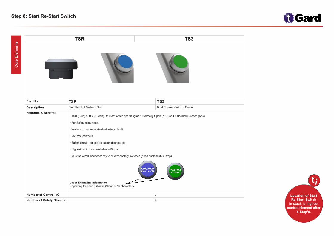
TSR TS3
Part No. TSR TS3Description Start Re-start Switch - Blue Start Re-start Switch - Green
Features & Benefits • TSR (Blue) & TS3 (Green) Re-start switch operating on 1 Normally Open (N/O) and 1 Normally Closed (N/C).
• For Safety relay reset.
• Works on own separate dual safety circuit.
• Volt free contacts.
• Safety circuit 1 opens on button depression.
• Highest control element after e-Stop’s.
• Must be wired independently to all other safety switches (head / solenoid / e-stop).
Laser Engraving Information: Engraving for each button is 2 lines of 10 characters.
Number of Control I/O 0
Number of Safety Circuits 2
iLocation of Start Re-Start Switch
in stack is highest control element after
e-Stop’s.
t
Step 9: Blue Independently Wired Switch & Potentiometer C
ore
Ele
men
ts
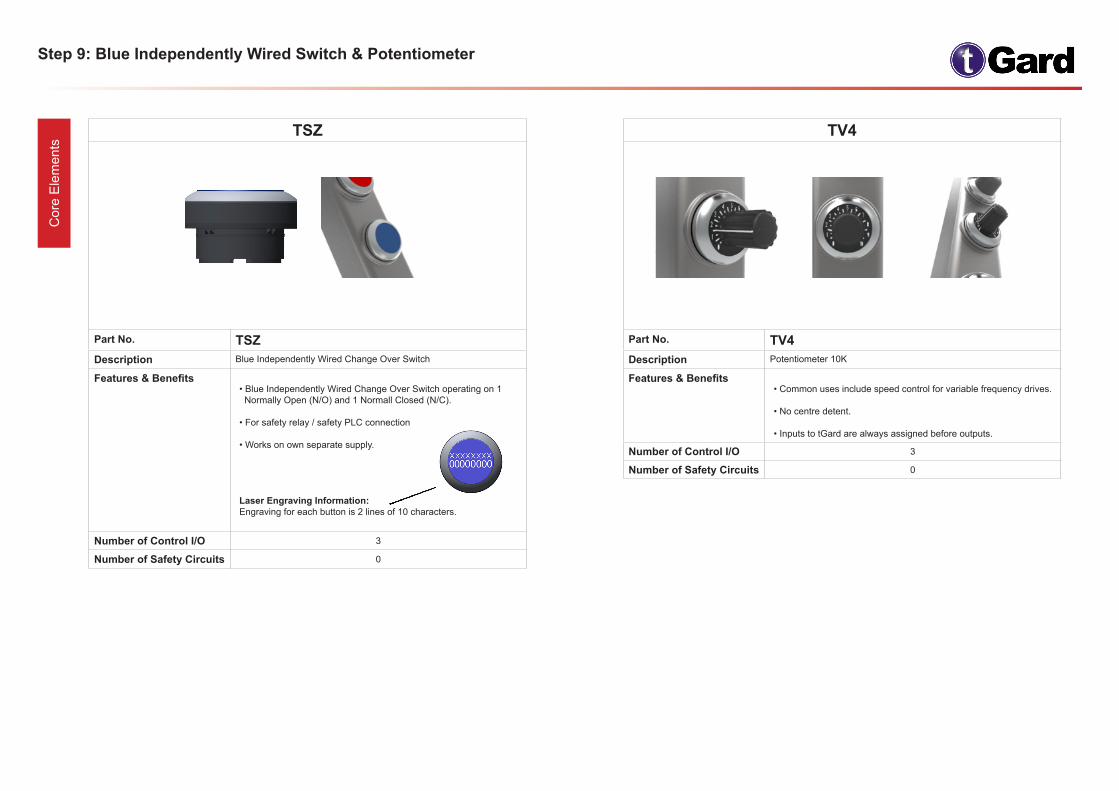
TSZ
Part No. TSZDescription Blue Independently Wired Change Over Switch
Features & Benefits • Blue Independently Wired Change Over Switch operating on 1 Normally Open (N/O) and 1 Normall Closed (N/C).
• For safety relay / safety PLC connection
• Works on own separate supply.
Laser Engraving Information: Engraving for each button is 2 lines of 10 characters.
Number of Control I/O 3
Number of Safety Circuits 0
TV4
Part No. TV4 Description Potentiometer 10K
Features & Benefits • Common uses include speed control for variable frequency drives.
• No centre detent.
• Inputs to tGard are always assigned before outputs.
Number of Control I/O 3
Number of Safety Circuits 0
Step 10a: Illuminating Switches C
ore
Ele
men
ts
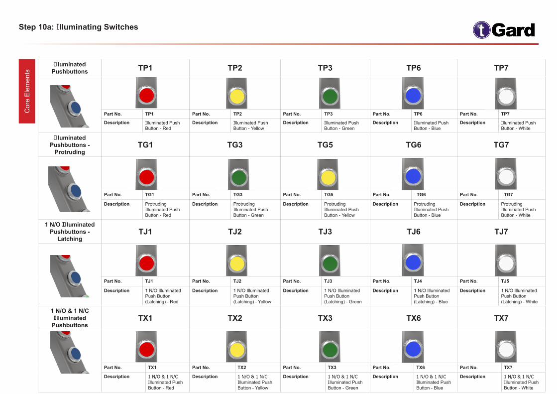
Illuminated Pushbuttons TP1 TP2 TP3 TP6 TP7
Part No. TP1 Part No. TP2 Part No. TP3 Part No. TP6 Part No. TP7
Description Illuminated Push Button - Red
Description Illuminated Push Button - Yellow
Description Illuminated Push Button - Green
Description Illuminated Push Button - Blue
Description Illuminated Push Button - White
Illuminated Pushbuttons -
ProtrudingTG1 TG3 TG5 TG6 TG7
Part No. TG1 Part No. TG3 Part No. TG5 Part No. TG6 Part No. TG7
Description Protruding Illuminated Push Button - Red
Description Protruding Illuminated Push Button - Green
Description Protruding Illuminated Push Button - Yellow
Description Protruding Illuminated Push Button - Blue
Description Protruding Illuminated Push Button - White
1 N/O Illuminated Pushbuttons -
LatchingTJ1 TJ2 TJ3 TJ6 TJ7
Part No. TJ1 Part No. TJ2 Part No. TJ3 Part No. TJ4 Part No. TJ5
Description 1 N/O Illuminated Push Button (Latching) - Red
Description 1 N/O Illuminated Push Button (Latching) - Yellow
Description 1 N/O Illuminated Push Button (Latching) - Green
Description 1 N/O Illuminated Push Button (Latching) - Blue
Description 1 N/O Illuminated Push Button (Latching) - White
1 N/O & 1 N/C Illuminated
Pushbuttons TX1 TX2 TX3 TX6 TX7
Part No. TX1 Part No. TX2 Part No. TX3 Part No. TX6 Part No. TX7
Description 1 N/O & 1 N/C Illuminated Push Button - Red
Description 1 N/O & 1 N/C Illuminated Push Button - Yellow
Description 1 N/O & 1 N/C Illuminated Push Button - Green
Description 1 N/O & 1 N/C Illuminated Push Button - Blue
Description 1 N/O & 1 N/C Illuminated Push Button - White
Step 10b: Illuminating Switches C
ore
Ele
men
ts
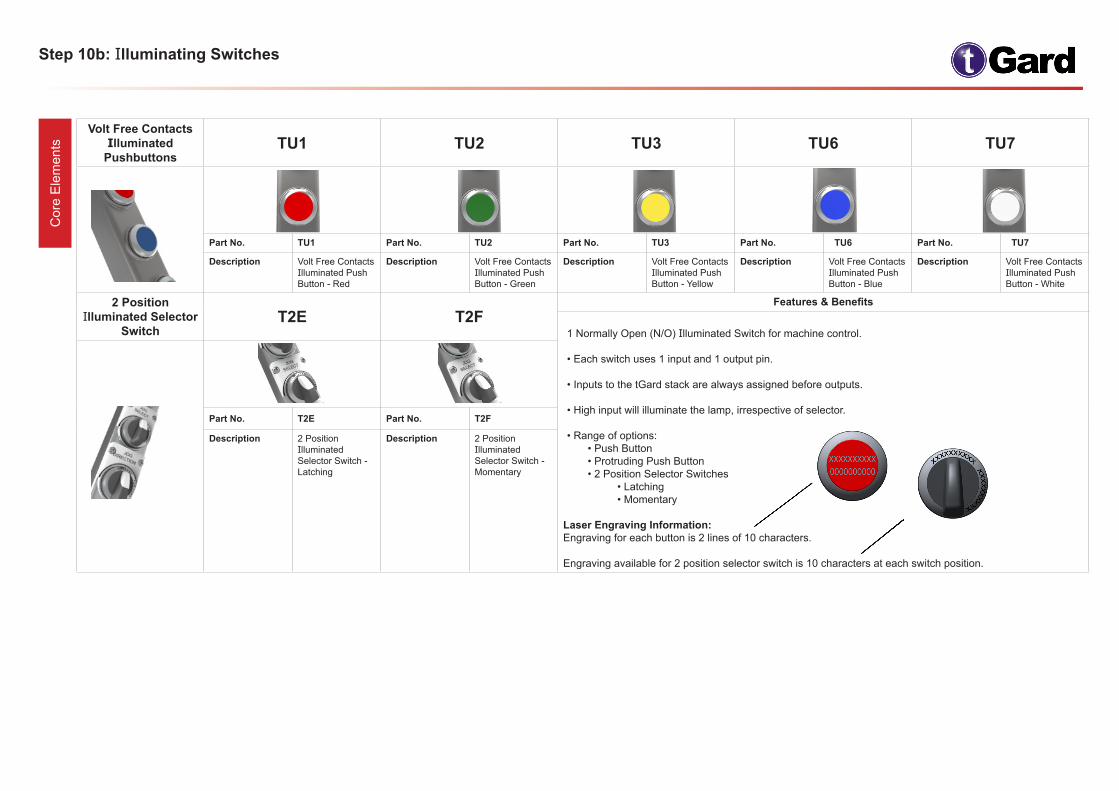
Volt Free Contacts Illuminated
PushbuttonsTU1 TU2 TU3 TU6 TU7
Part No. TU1 Part No. TU2 Part No. TU3 Part No. TU6 Part No. TU7
Description Volt Free Contacts Illuminated Push Button - Red
Description Volt Free Contacts Illuminated Push Button - Green
Description Volt Free Contacts Illuminated Push Button - Yellow
Description Volt Free Contacts Illuminated Push Button - Blue
Description Volt Free Contacts Illuminated Push Button - White
2 Position Illuminated Selector
SwitchT2E T2F
Features & Benefits
1 Normally Open (N/O) Illuminated Switch for machine control.
• Each switch uses 1 input and 1 output pin.
• Inputs to the tGard stack are always assigned before outputs.
• High input will illuminate the lamp, irrespective of selector.
• Range of options: • Push Button • Protruding Push Button • 2 Position Selector Switches • Latching • Momentary
Laser Engraving Information:Engraving for each button is 2 lines of 10 characters.
Engraving available for 2 position selector switch is 10 characters at each switch position.
Part No. T2E Part No. T2F
Description 2 Position Illuminated Selector Switch - Latching
Description 2 Position Illuminated Selector Switch - Momentary
Step 11a: Non-Illuminating Switches C
ore
Ele
men
ts
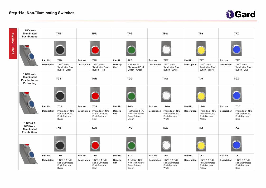
1 N/O Non-Illuminated
Pushbuttons TPB TPR TPG TPW TPY TPZ
Part No. TPB Part No. TPR Part No. TPG Part No. TPW Part No. TPY Part No. TPZ
Description 1 N/O Non- Illuminated Push Button - Black
Description 1 N/O Non- Illuminated Push Button - Red
Descrip-tion
1 N/O Non- Illuminated Push Button - Green
Description 1 N/O Non- Illuminated Push Button - White
Description 1 N/O Non- Illuminated Push Button - Yellow
Description 1 N/O Non- Illuminated Push Button - Blue
1 N/O Non- Illuminated
Pushbuttons - Protruding
TGB TGR TGG TGW TGY TGZ
Part No. TGB Part No. TGR Part No. TGG Part No. TGW Part No. TGY Part No. TGZ
Description Protruding 1 N/O Non-Illuminated Push Button - Black
Description Protruding 1 N/O Non-Illuminated Push Button - Red
Descrip-tion
Protruding 1 N/O Non-Illuminated Push Button - Green
Description Protruding 1 N/O Non-Illuminated Push Button - White
Description Protruding 1 N/O Non-Illuminated Push Button - Yellow
Description Protruding 1 N/O Non-Illuminated Push Button - Blue
1 N/O & 1 N/C Non-
Illuminated Pushbuttons
TXB TXR TXG TXW TXY TXZ
Part No. TXB Part No. TXR Part No. TXG Part No. TXW Part No. TXY Part No. TXZ
Description 1 N/O & 1 N/C Non-Illuminated Push Button - Black
Description 1 N/O & 1 N/C Non-Illuminated Push Button - Red
Descrip-tion
1 N/O & 1 N/C Non-Illuminated Push Button - Green
Description 1 N/O & 1 N/C Non-Illuminated Push Button - White
Description 1 N/O & 1 N/C Non-Illuminated Push Button - Yellow
Description 1 N/O & 1 N/C Non-Illuminated Push Button - Blue
Step 11b: Non-Illuminating SwitchesC
ore
Ele
men
ts
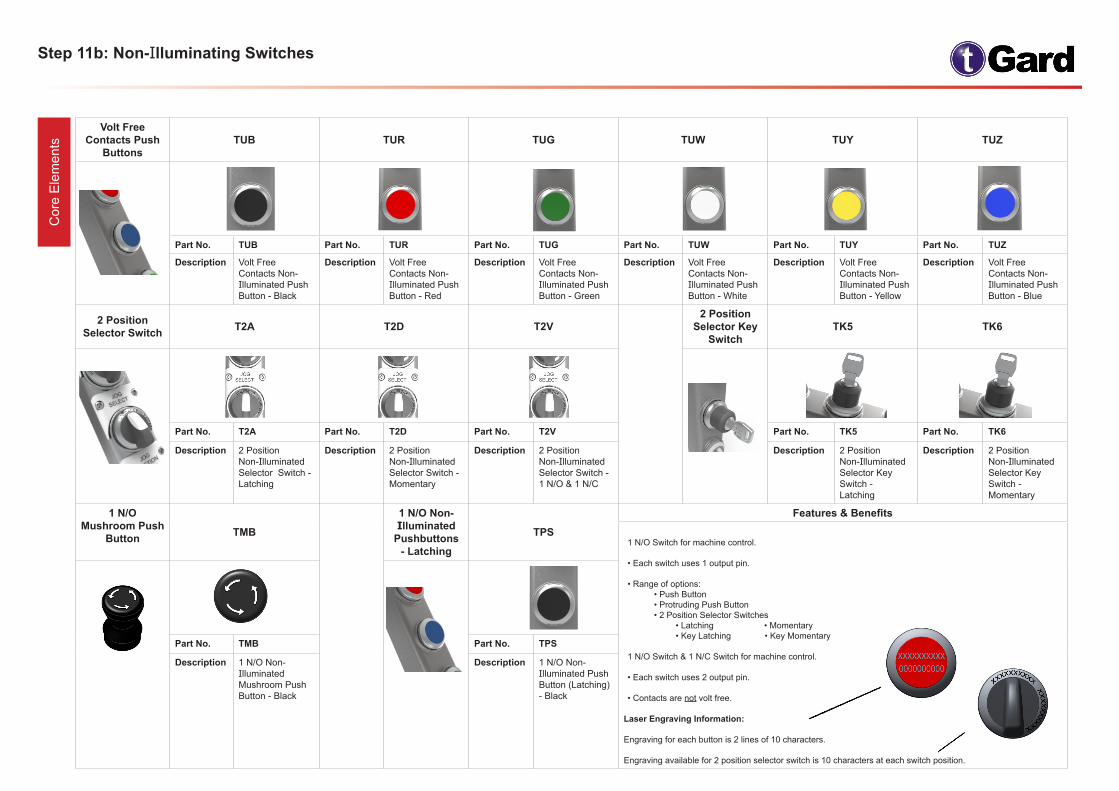
Volt Free Contacts Push
Buttons TUB TUR TUG TUW TUY TUZ
Part No. TUB Part No. TUR Part No. TUG Part No. TUW Part No. TUY Part No. TUZ
Description Volt Free Contacts Non-Illuminated Push Button - Black
Description Volt Free Contacts Non-Illuminated Push Button - Red
Description Volt Free Contacts Non-Illuminated Push Button - Green
Description Volt Free Contacts Non-Illuminated Push Button - White
Description Volt Free Contacts Non-Illuminated Push Button - Yellow
Description Volt Free Contacts Non-Illuminated Push Button - Blue
2 Position Selector Switch T2A T2D T2V
2 Position Selector Key
SwitchTK5 TK6
Part No. T2A Part No. T2D Part No. T2V Part No. TK5 Part No. TK6
Description 2 Position Non-Illuminated Selector Switch - Latching
Description 2 Position Non-Illuminated Selector Switch - Momentary
Description 2 Position Non-Illuminated Selector Switch - 1 N/O & 1 N/C
Description 2 Position Non-Illuminated Selector Key Switch - Latching
Description 2 Position Non-Illuminated Selector Key Switch - Momentary
1 N/O Mushroom Push
Button TMB
1 N/O Non- Illuminated
Pushbuttons - Latching
TPS
Features & Benefits
1 N/O Switch for machine control.
• Each switch uses 1 output pin.
• Range of options: • Push Button • Protruding Push Button • 2 Position Selector Switches • Latching • Momentary • Key Latching • Key Momentary
1 N/O Switch & 1 N/C Switch for machine control.
• Each switch uses 2 output pin.
• Contacts are not volt free.
Laser Engraving Information:
Engraving for each button is 2 lines of 10 characters.
Engraving available for 2 position selector switch is 10 characters at each switch position.
Part No. TMB Part No. TPS
Description 1 N/O Non-Illuminated Mushroom Push Button - Black
Description 1 N/O Non- Illuminated Push Button (Latching) - Black
Step 12: LED Lamp Element C
ore
Ele
men
ts
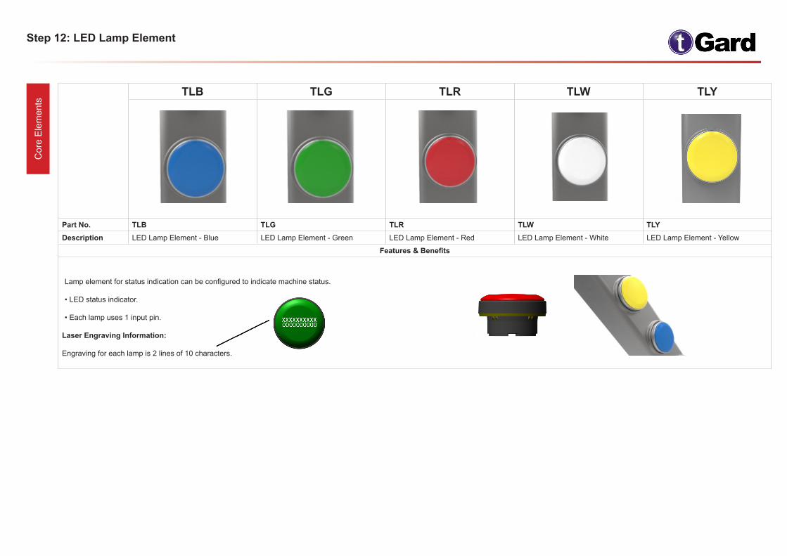
TLB TLG TLR TLW TLY
Part No. TLB TLG TLR TLW TLYDescription LED Lamp Element - Blue LED Lamp Element - Green LED Lamp Element - Red LED Lamp Element - White LED Lamp Element - Yellow
Features & Benefits
Lamp element for status indication can be configured to indicate machine status.
• LED status indicator.
• Each lamp uses 1 input pin.
Laser Engraving Information:
Engraving for each lamp is 2 lines of 10 characters.
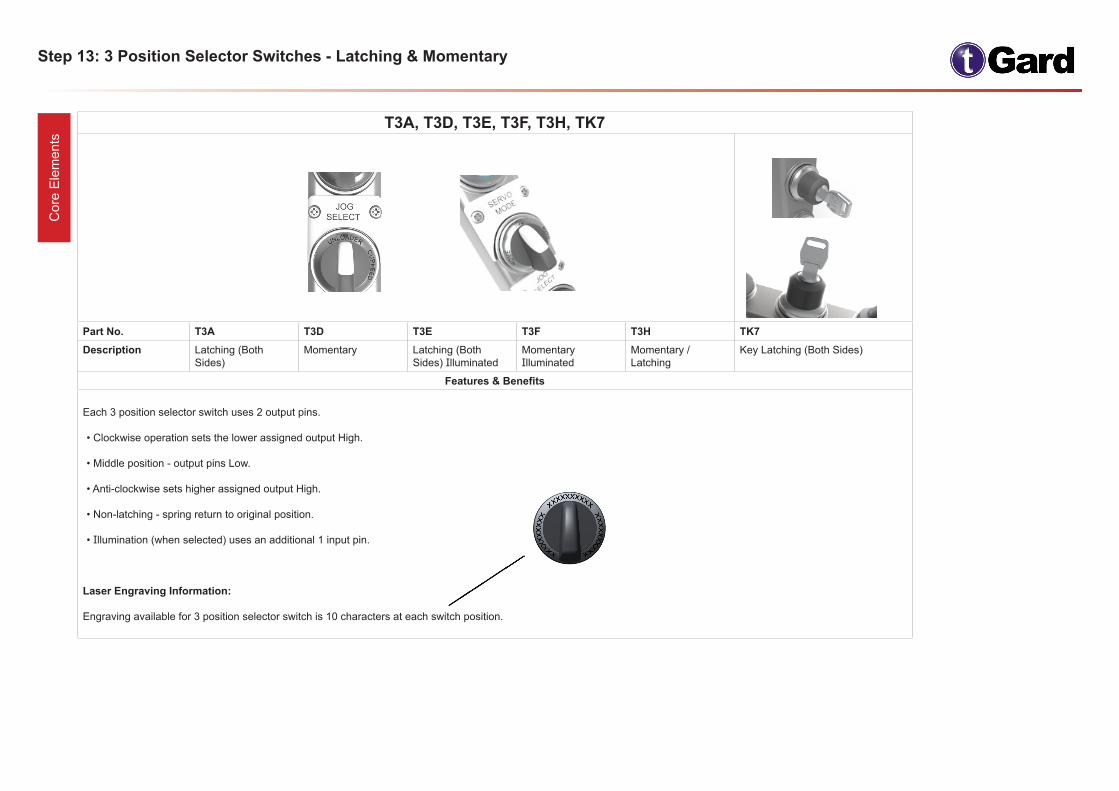
T3A, T3D, T3E, T3F, T3H, TK7
Part No. T3A T3D T3E T3F T3H TK7Description Latching (Both
Sides)Momentary Latching (Both
Sides) IlluminatedMomentary Illuminated
Momentary / Latching
Key Latching (Both Sides)
Features & Benefits
Each 3 position selector switch uses 2 output pins.
• Clockwise operation sets the lower assigned output High.
• Middle position - output pins Low.
• Anti-clockwise sets higher assigned output High.
• Non-latching - spring return to original position.
• Illumination (when selected) uses an additional 1 input pin.
Laser Engraving Information:
Engraving available for 3 position selector switch is 10 characters at each switch position.
Step 13: 3 Position Selector Switches - Latching & Momentary C
ore
Ele
men
ts
Step 14: Foot, Safety & Control Connectors B
ase
Ele
men
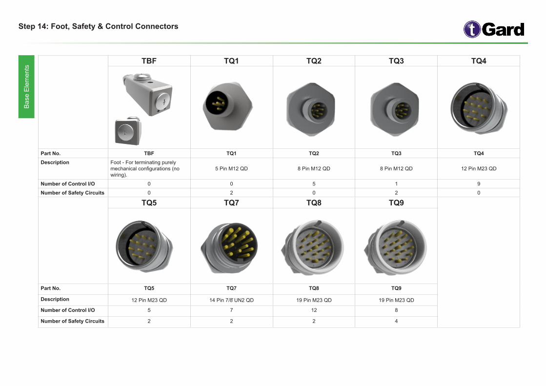
ts TBF TQ1 TQ2 TQ3 TQ4
Part No. TBF TQ1 TQ2 TQ3 TQ4Description Foot - For terminating purely
mechanical configurations (no wiring).
5 Pin M12 QD 8 Pin M12 QD 8 Pin M12 QD 12 Pin M23 QD
Number of Control I/O 0 0 5 1 9
Number of Safety Circuits 0 2 0 2 0
TQ5 TQ7 TQ8 TQ9
Part No. TQ5 TQ7 TQ8 TQ9
Description 12 Pin M23 QD 14 Pin 7/8̎ UN2 QD 19 Pin M23 QD 19 Pin M23 QD
Number of Control I/O 5 7 12 8
Number of Safety Circuits 2 2 2 4
Step 15: Mating Cables for Quick Disconnect Connectors B
ase
Ele
men
ts
Connector Type
Cable Length
Cable Part Number
TQ1
2M Cable-2M-TQ1
5M Cable-5M-TQ1
10M Cable-10M-TQ1
20M Cable-20M-TQ1
TQ2
2M Cable-2M-TQ2
5M Cable-5M-TQ2
10M Cable-10M-TQ2
20M Cable-20M-TQ2
TQ3
2M Cable-2M-TQ3
5M Cable-5M-TQ3
10M Cable-10M-TQ3
20M Cable-20M-TQ3
TQ4
2M Cable-2M-TQ4
5M Cable-5M-TQ4
10M Cable-10M-TQ4
20M Cable-20M-TQ4
TQ5
2M Cable-2M-TQ5
5M Cable-5M-TQ5
10M Cable-10M-TQ5
20M Cable-20M-TQ5
TQ7
2M Cable-2M-TQ7
5M Cable-5M-TQ7
10M Cable-10M-TQ7
20M Cable-20M-TQ7
TQ8
2M Cable-2M-TQ8
5M Cable-5M-TQ8
10M Cable-10M-TQ8
20M Cable-20M-TQ8
TQ9
2M Cable-2M-TQ9
5M Cable-5M-TQ9
10M Cable-10M-TQ9
20M Cable-20M-TQ9
Part No. Pin Heads
Cab
le-_
M-T
Q1
Cab
le-_
M-T
Q2
/ TQ
3C
able
-_M
-TQ
4 / T
Q5
Cab
le-_
M-T
Q7
Cab
le-_
M-T
Q8
/ TQ
9
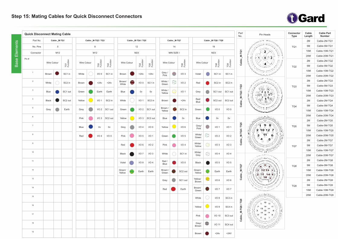
Quick Disconnect Mating Cable
Part No. Cable-_M-TQ1 Cable-_M-TQ2 / TQ3 Cable-_M-TQ4 / TQ5 Cable-_M-TQ7 Cable-_M-TQ8 / TQ9
No. Pins 5 8 12 14 19
Connector M12 M12 M23 MIN SIZE I M23
Pin #
Wire ColourTQ
1Fu
nctio
n
Wire Colour
TQ2
Func
tion
TQ3
Func
tion
Wire Colour
TQ4
Func
tion
TQ5
Func
tion
Wire Colour
TQ6
Func
tion
Wire Colour
TQ8
Func
tion
TQ9
Func
tion
1Brown SC1 in White I/O 0 SC1 in Brown +24v +24v Grey /
Pink I/O 3 Violet SC1 in SC1 in
2White SC2 in Brown +24v +24v Brown/
White I/O 0 SC1 in White / Green I/O 2 Red SC2 in SC2 in
3Blue SC1 out Green Earth Earth Blue 0v 0v White /
Yellow I/O 1 Grey SC1 out SC1 out
4Black SC2 out Yellow I/O 1 SC2 in White I/O 1 SC2 in Brown +24v Red/
Blue SC2 out SC2 out
5Grey Earth Grey I/O 2 SC1 out Green I/O 2 SC1 out Brown /
Yellow SC2 in Green I/O 0 I/O 0
6 Pink I/O 3 SC2 out Yellow I/O 3 SC2 out Blue 0v Blue 0v 0v
7 Blue 0v 0v Grey I/O 4 I/O 0 Yellow I/O 6 Grey/
Pink I/O 1 I/O 1
8 Red I/O 4 I/O 0 Pink I/O 5 I/O 1 Green I/O 5 White/
Green I/O 2 I/O 2
9Red I/O 6 I/O 2 Pink I/O 4 White/
Yellow I/O 3 I/O 3
10Black I/O 7 I/O 3 White SC1 in White/
Grey I/O 4 I/O 4
11Violet I/O 8 I/O 4 Red /
Blue I/O 0 Black I/O 5 I/O 5
12 Green/ Yellow Earth Earth Brown /
Green SC2 out Green/Yellow Earth Earth
13Grey SC1 out Yellow/
Brown I/O 6 I/O 6
14Red Earth Brown/
Green I/O 7 I/O 7
15White I/O 8 SC3 in
16Yellow I/O 9 SC4 in
17Pink I/O 10 SC3 out
18 Grey/ Brown I/O 11 SC4 out
19Brown +24v +24V

Step 16: Self Wire Connectors B
ase
Ele
men
ts TW1 TW3 TW4
Part No. TW1 TW3 TW4Description 12 Terminals 24 Terminals 24 Terminals
Number of Control I/O 6 14 10
Number of Safety Circuits 2 4 6
Features & Benefits
• For applications where the customer wishes to make their own connections.
• Push fit terminals.
• Cable size 26-14 AWG.
• Available with 12 or 24 connections.
• Control only and Safety and Control versions available.
• M20 gland thread.
• Requires no additional mounting to frame.
• Large opening for easy wiring.
Step 17: As-interface B
ase
Ele
men
ts TEBB4 TEBB8
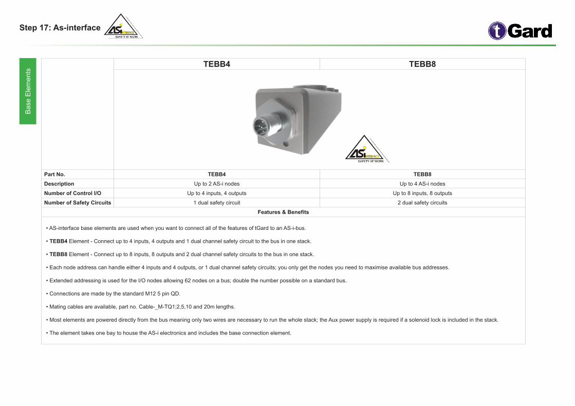
Part No. TEBB4 TEBB8Description Up to 2 AS-i nodes Up to 4 AS-i nodes
Number of Control I/O Up to 4 inputs, 4 outputs Up to 8 inputs, 8 outputs
Number of Safety Circuits 1 dual safety circuit 2 dual safety circuits
Features & Benefits
• AS-interface base elements are used when you want to connect all of the features of tGard to an AS-i-bus.
• TEBB4 Element - Connect up to 4 inputs, 4 outputs and 1 dual channel safety circuit to the bus in one stack.
• TEBB8 Element - Connect up to 8 inputs, 8 outputs and 2 dual channel safety circuits to the bus in one stack.
• Each node address can handle either 4 inputs and 4 outputs, or 1 dual channel safety circuits; you only get the nodes you need to maximise available bus addresses.
• Extended addressing is used for the I/O nodes allowing 62 nodes on a bus; double the number possible on a standard bus.
• Connections are made by the standard M12 5 pin QD.
• Mating cables are available, part no. Cable-_M-TQ1;2,5,10 and 20m lengths.
• Most elements are powered directly from the bus meaning only two wires are necessary to run the whole stack; the Aux power supply is required if a solenoid lock is included in the stack.
• The element takes one bay to house the AS-i electronics and includes the base connection element.
Step 18: Accessories A
cces
sorie
s
TKS TKM
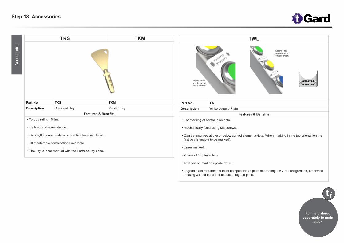
Part No. TKS TKM Description Standard Key Master Key
Features & Benefits• Torque rating 10Nm.
• High corrosive resistance.
• Over 5,000 non-masterable combinations available.
• 10 masterable combinations available. • The key is laser marked with the Fortress key code.
TWL
Part No. TWLDescription White Legend Plate
Features & Benefits• For marking of control elements.
• Mechanically fixed using M3 screws.
• Can be mounted above or below control element (Note: When marking in the top orientation the first bay is unable to be marked).
• Laser marked.
• 2 lines of 10 characters.
• Text can be marked upside down.
• Legend plate requirement must be specified at point of ordering a tGard configuration, otherwise housing will not be drilled to accept legend plate.
Legend Plate mounted above control element
Legend Plate mounted belowcontrol element
i
Item is ordered separately to main
stack
t