part number: cobra-75 - ron francis wiring · part number: cobra-75 ron francis wiring & the...
TRANSCRIPT
Ford 5.0 EFI Harness
Installation Manual for Wiring Kit
U
n
i
v
e
r
s
a
l
F
i
t
Part Number: Cobra-75
Ron Francis Wiring & The Detail Zone
200 Keystone Rd. Chester, PA 19013
877-968-7842 www.ronfrancis.com
Pre-Installation Notes:
• This system is designed to install Mass Air Flow based Ford EFI 5.0 & 5.8 engines.
• Make sure that all the components you have are compatible before installing them.
• Intakes are fairly interchangeable, make sure the upper and lower intakes match, and
the lower intake has a port for the Air Charge Temp sensor (ACT) sensor.
• The fuel rail will dictate which side the intake faces, make sure you have the correct
one. This harness is set up for a passenger side facing intake when in stock form.
• This harness does not include provisions for emissions and is not intended for installation on
emission controlled vehicles.
• The distributor should be specific for your engine (5.0L / 5.8L) and have the TFI
Ignition Module mounted onto the side.
• This harness is set up for a “High Output” firing order of 1-3-7-2-6-5-4-8 in its
stock form. Make sure your camshaft and computer match this order.
• Ford EFI systems were not intended for use with long tube headers. The Oxygen
Sensors are less accurate (due to dissipated exhaust heat) when mounted
further down stream from the cylinder head. However this harness will work with
all exhaust systems.
• Always disconnect the battery when working on vehicles fuel or electrical
systems. Any electrical spikes can damage parts of the fuel injection system.
• Use extreme caution if and when welding on any vehicle with a fuel injection system.

Pre-Installation Instructions:
Install the lower intake, fuel injectors, and fuel rail on the engine if not already installed. Remove the
upper intake if it is installed and install stock fuel pressure regulator. Plumb fuel lines with appropriately rated
line. Use caution when working on fuel system, 40-100PSI can be held within system. To release fuel
pressure, remove fuse or relay to fuel pump(s), then start engine and allow it to stall. Crank starter for several
seconds to insure all pressure has been released.
Before installation spread out the harness in a well lighted open area to identify all the connectors and
become familiar with what will need to be done.
19) Vehicle Speed sensor
18) R & L Oxygen sensors
15) Air Charge Temp sensor
20) Fuel Pump Connection
1) EEC Computer connector 8) Mass Air sensor 16) TFI Distributor connector
2) Inertia Fuel Cutoff Switch 9) Ground 17) SPOUT Connector 3) Ignition, Start, Tachometer & Check 10) Throttle Position sensor
Engine Light connections 11) Idle Air Bypass 4) Self-Test connectors 12) Engine Coolant Temp Sensor
5) Transmission ID Plugs 13) Barometric Pressure sensor 21) Ignition Coil plug 6) Relay Block 14) Injectors 22) Alternator connection
7) Fuse Block and Battery connection

Installation Instructions:
1 Lay the harness into the engine compartment with the relay and fuse blocks on
the passenger side.
2 Locate where in the firewall you wish to route the computer plug and other dash connections. Using the grommet supplied, cut the appropriate hole
in the firewall. Use the following template for the grommet:
3 Pass the engine section of the harness through the firewall. Route as much of the harness as possible before mounting the computer or covering the harness. This
ensures a quality installation.
4 Remove the last bolt holding the lower intake down on the passenger side. Install #9 engine ground and torque the bolt back down to specifications. This is extremely important and should be the first connections made!
5 Install all eight fuel injector connectors starting with cylinder #1 and working your way around. Connecting the injectors now helps get the majority of the harness into position.
6 Connect #12 Engine Coolant Temp sensor and #15 Air Charge Temp sensor.
7 Route #18 Right & Left O2 sensors, #19 Vehicle Speed sensor, and #20 Fuel Pump power wires down to their locations under vehicle. Route #19 Vehicle Speed sensor and #20 Fuel Pump power connectors along the left frame rail.
Keep them away from hot exhaust moving parts like driveshaft.

8 Weld exhaust bungs into both sides of the exhaust approximately 9-12 inches
from the last cylinder head exhaust port or 3” from the collector. Clean any
debris from oxygen sensor ports and threads.
a) Use a small amount of anti-seize on the threads when installing Oxygen Sensors. Use SG23 Oxygen sensors with short headers. Use SG40 Oxygen Sensors with long tube headers.
b) Connect #18, oxygen sensors to their connectors and attach any free harness to the firewall or frame to keep them from falling against the exhaust.
9 Install Vehicle Speed Sensor between the transmission and speedometer cable. Route #19 Vehicle Speed Sensor connector along the left frame rail and plug into the Vehicle Speed Sensor.
10 #20 is a 14Ga pink wire to power your fuel pump(s); you will need to splice this wire if you are using 2 fuel pumps that are not mounted together. Make sure the fuel pump(s) are well grounded.
11 Carefully route #21 Ignition Coil connector along firewall and fender to the coil. Keep Radio power wires and antenna cables away from Ignition Coil to prevent future distortion or interference.
12 #3 is a group of wires under the dash.
Color Printing Purpose
Orange Keyed Run Ignition Power Supply
Purple Start Start Signal for ECM
Green Tach Tachometer
Tan MIL Check Engine Check Engine Light Negative
Red MIL Check Engine
Positive
Check Engine Light Positive
A) Connect the Orange wire marked “Keyed Run” to the keyed ignition switch hot wire.
This wire must have +12 volts with the key in run and start positions.
B) Connect the Purple wire marked “Start” to the keyed ignition start wire. This wire
must have +12 volts only when the key is in the start position.
***This circuit should only be hot when the key is cranking the engine. The intent
Is that the system retards timing during crank to help the engine start up. If you
connect this wire to always hot with key on you will experience an undesirable
rev limiter at 2000-3000 RPM’s.
C) The Green wire marked “Tach” is for your tachometer. Connect to your tach.
Refer to the tachometer manufacturer’s information for any additional details.
D) Connect the Tan marked “MIL” and Red marked “MIL Power” to your check engine light.
This must be a light that is not self grounding and needs two leads, both power and ground.
13 You can install the upper intake plenum onto the lower intake and install the
throttle body to the upper intake. Now would also be a good time to finish the
vacuum system.
14 Connect #10 Throttle Position sensor and #11 Idle Air Bypass.
15 Install the Mass Air Flow Meter, air filter and air tubes. Connect the MAF to the
harness connection #8.
16 Mount the Barometric Pressure sensor to the firewall or inner fender and
connect it to the harness at #13.
17 Before you install the distributor, make sure the engine is at TDC for cylinder #1 and
you have mounted the TFI to the side of the distributor. Drop the distributor into position
so the rotor is aligned with the 1 molded into the cap. Make sure there is enough room
to rotate the distributor in the block 1/8th of a turn. You will need to rotate it to set the
base timing to 10 degrees BTDC.
Connect #16 to the TFI module on the distributor and make sure that #17 SPOUT
connector is connected firmly. Only disconnect the SPOUT to check and set the base
timing.
18 Locate #5 the transmission identification terminals near the Self-Test
connectors. You need to plug the male terminal into one of the female terminals,
depending on which computer type you are using. The male plug is labeled “TRANS” and
the female plugs are labeled “AUTO” & “MAN.” You need to identify your computer as an
automatic or manual transmission computer by its sticker. If you are unsure which
computer you have your local Ford dealer should be able to help.
a) If your computer is for an automatic transmission; connect “TRANS” plug to the
Black “AUTO” plug.
b) If your computer is for a manual transmission; connect “TRANS” plug to the
Gray “MAN” plug.
19 It is advised that you use an inertia switch to turn off the fuel pump(s) in the event of a crash. Under the dash is connector #2 for the Inertia Fuel Cutoff Switch. Mount the Inertia Switch completely upright and connect it to the harness.
Mounting the switch any other way or bypassing this switch can cause risk or
fire or loss of life. Before continuing, tap the switch until the button on top pops
up and reset it. This will confirm its action and get you familiar with how it
works.
20 Connector #1 is for the computer, make sure the computer pins are not bent or damaged. Then connect the harness with a 10mm socket. DO NOT use air or power tools to install this connector!
21 Next to the Fuse & Relay blocks is a large 10Ga red wire connect this 10Ga Red 3/8”
terminal to Battery Positive or the starter solenoid.
22 #22 is ignition power wire for your alternator. It is not meant to charge the vehicle, but to turn the alternator ON when you turn the key to RUN. Consult your alternator installation manual for further instructions.
23 Please take the time to run a Self-Test at #4 prior to starting the engine. This will clue you in to any connections you missed, and give you a base line to compare future tests against.
24 If this is the first fuel injection installation on this vehicle run the fuel pump(s) for 30-60 seconds to create fuel pressure for the injectors. To do this, ground the terminal on the end of the larger Self-Test connector marked ECM 22->VIP. Codes 33, 44, 81, 82, 84, 85 and 94 are what’s called “soft” codes and do not affect the engine fuel or spark programming. These codes will set due to the smog solenoids CANP, EGR, TAB and TAD being removed. Soft codes harmlessly stay dormant in the computer. Their purpose is to help aid in the repair of those systems. Soft codes will not turn on the Check Engine Light. There is a resistor pack already installed in this harness for the EGR Valve Position Sensor. No other resistors are required.
USING THE CHECK ENGINE LIGHT The check engine light performs just the same as it would in any newer car, when the key is turned on (engine not running) the light will stay on till the engine starts.
When the check engine light comes on during engine operation, it is an indication of a fault in the system. It will be necessary to have the computer perform a self test diagnostic procedure. The self test is divided into three specialized tests:
KEY ON ENGINE OFF SELF TEST: For this test the fault must be present at the time of testing. For intermittent problems refer to continuous memory codes.
ENGINE RUNNING SELF TEST: The sensors are checked under operating conditions and at normal operating temperatures.
CONTINUOUS MEMORY CODES: These codes are issued as a result of information stored while the vehicle was in normal operation.
READING THE CHECK ENGINE LIGHT: A service code is reported by a flash of the check engine light. All service codes are two digit numbers, such as 2-3. The light will display two flashes, then, after a two second pause, the light will flash three times. All self test codes (if any) will be displayed and then a delay of six seconds, a single half second separator flash and another six second delay and then the continuous memory codes will be flashed.
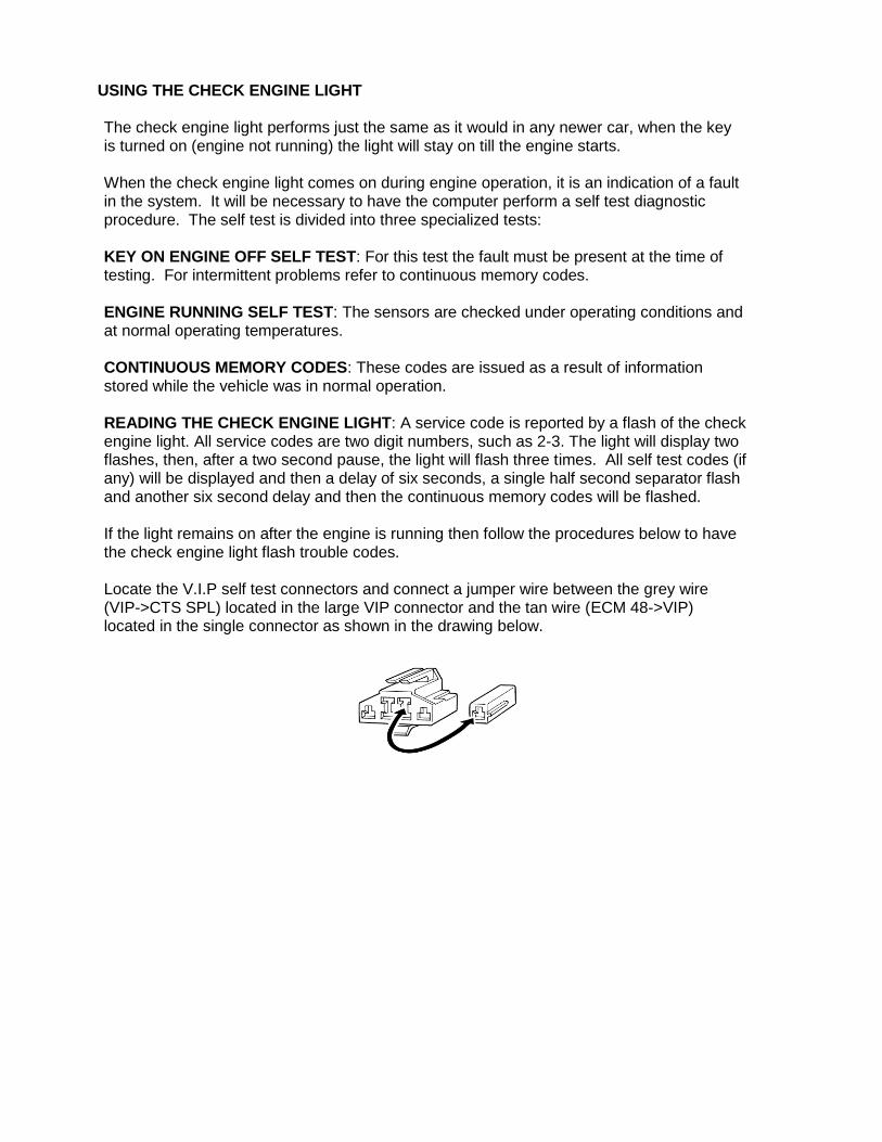
If the light remains on after the engine is running then follow the procedures below to have the check engine light flash trouble codes.
Locate the V.I.P self test connectors and connect a jumper wire between the grey wire (VIP->CTS SPL) located in the large VIP connector and the tan wire (ECM 48->VIP) located in the single connector as shown in the drawing below.

Trouble Codes
11 System PASS 12 High RPM 13 Low RPM 14 PIP circuit failure 15 ECG memory failure 16 RPM low for EGO test 18 SPOUT /IDM circuit failure 19 ECG internal voltage failure 21 ECT out of test range 22 MAP /BP out of test range 23 TP out of test range 24 ACT of test range 26 MAF out of test range 29 Vehicle speed sensor problem 31 EVP voltage below minimum 32 EVP voltage below closed limit 33 EGR valve opening not detected 34 EVP voltage above closed limit 35 EVP voltage above maximum 41 HEGO (R) sensor lean or defective 42 HEGO (R) sensor rich 44 Thermactor air system defective (R) 45 Thermactor air upstream during self test 46 Thermactor air not bypassed during self test 51 ECT indicated -40NF/open circuit 53 TP circuit above maximum voltage 54 ACT indicated -40NF/circuit open 56 MAF circuit above max voltage 61 ECT indicated 254NF/circuit grounded 63 TP circuit below minimum voltage 64 ACT indicated 254NF/circuit grounded 66 MAF circuit below minimum voltage 67 Neutral drive switch circuit open 74 Brake on/off circuit open during self test 75 Brake on/off circuit closed/ ECG input open 77 Brief WOT not sensed during self test 79 A/C on defrost on during self test 81 Air management 2 circuit failure 82 Air management 1 circuit failure 84 EGR Vacuum Regulator circuit failure 85 Canister purge circuit failure 87 Fuel pump primary circuit failure 91 HEGO (L) sensor lean or defective 92 HEGO (L) sensor rich 94 Thermactor air system inoperative (L) 95 Fuel pump secondary circuit failure 96 Fuel pump secondary circuit failure 98 Hard fault present FMEM mode
No codes = unable to indicate self test
Code not listed = Not applicable to this engine

The following diagram shows some of the sensor locations on a typical Ford 5.0 engine. The sensors not shown are mounted remote (off the engine) on the stock vehicle application. Your
installation may require these items not to be mounted in the same location as on a factory installation. The numbers before the sensor names correspond to the numbers shown in the
drawing. 1) Air Charge Temperature Sensor 2) Shorting Plug 3) TFI Ignition Module 4) Coolant Temperature Sensor 5) Idle Speed Control 6) Mass Air Flow Sensor 7) Throttle Position Sensor 8) Right O2 Sensor 9) EGR Valve Position Sensor 10) Injectors 11) Left O2 Sensor

COMPATIBLE FORD 5.0 AND ASSOCIATED PARTS ECM FOR MANUAL TRANSMISSION (A9L) FORD F3ZF-12A650-DB
STANDARD MOTOR PRODUCTS EM073
A1-CARDONE 78-4352
ECM FOR AUTO TRANSMISSION (A9P) FORD F3ZF-12A650-FB
STANDARD MOTOR PRODUCTS EM680
A1-CARDONE 78-5611
MASS AIR FLOW METER FORD E9ZF-12B579-AA
STANDARD MOTOR PRODUCTS MF0872
A1-CARDONE 74-9502
IDLE AIR BYPASS VALVE FORD F0AE-9F715-BA
STANDARD MOTOR PRODUCTS AC21
AIR CHARGE TEMP SENSOR FORD F2DZ-12A697-A
STANDARD MOTOR PRODUCTS AX3
BAROMETRIC AIR PRESSURE SENSOR FORD MOTORCRAFT DY530
STANDARD MOTOR PRODUCTS AS13
ENGINE COOLANT TEMP SENSOR FORD F2AF-12A648-AA
STANDARD MOTOR PRODUCTS TX6
OXYGEN SENSOR WITH 8 INCH LEAD FORD E9SF-9F472-AA
STANDARD MOTOR PRODUCTS SG23
BOSCH 13942
OXYGEN SENSOR WITH 16 INCH LEAD FORD E7TF-9F472-CA
STANDARD MOTOR PRODUCTS SG40
BOSCH 13953
THROTTLE POSITION SENSOR FORD E8ZF-9F989-AA
STANDARD MOTOR PRODUCTS TH72
VEHICLE SPEED SENSOR FORD E9TZ-9E731-A
STANDARD MOTOR PRODUCTS SC37
INERTIA SWITCH FORD XF3Z-9341-AA
AIRTEX 1S3906
FUEL INJECTOR (STOCK 19 LB/HR) ORANGE FORD F1ZZ-9F593-C
STANDARD MOTOR PRODUCTS FJ68
FUEL PRESSURE REGULATOR FORD F4CZ-9C968-A
STANDARD MOTOR PRODUCTS PR15

COMPATIBLE FORD 5.0 AND ASSOCIATED PARTS DISTRIBUTOR 5.0 WITH ROLLER CAM FORD RACING M-12127-C302
A1-CARDONE 302892
DISTRIBUTOR 5.0 WITH STANDARD CAM A1-CARDONE 302880
DISTRIBUTOR 5.8 WITH STANDARD CAM A1-CARDONE 302884
DISTRIBUTOR 7.5 WITH STANDARD CAM A1-CARDONE 302886
Fuse and Relay Key
Fuse and Relay
Designation
Fuse Size
O2 & Mass Air Flow Sensor (Relay A)
15 AMP
Fuel Pump (Relay B)
20 AMP
Coil & TFI Module
(Relay C)
15 AMP
ECM, Injectors, IAC
(Relay D)
20 AMP
Tech Line Number: 610-485-1981 When calling please have the harness serial number handy. The serial number can be found on your paperwork or on the grey ECM connector. You will have to loosen the ECM to find it.
Warranty Information
All Ron Francis Wiring products are warranted for 1 year from purchase date. There are no other representations, warranties or conditions expressed or implied, statutory or otherwise
except those herein contained. Warranty does not cover any defect which is the result of improper installation or modification of the system or any of its components by purchaser.
Ron Francis Wiring, its dealers or agents will not be liable, in any way, for any damage, loss, injury or other claims, resulting from the use or misuse, or inability to use any of our products. Purchaser and/or user, assumes liability of any kind connected with the use and/or application
of our products.
Copyright @ 2006 Wire Works Enterprises Inc.