part nos. 6852m (6-a) and 6853m...
TRANSCRIPT

1MALLORY TECHNICAL SUPPORT (216) 688-8300 [email protected]
HYFIRE® 6A and 6AL SERIESELECTRONIC IGNITION CONTROL
PART NOS. 6852M (6-A) and 6853M (6-AL)
INSTALLATION INSTRUCTIONSFORM 1522TL
GENERAL INFORMATION
The features of the HYFIRE® 6-A and HYFIRE® 6-AL are the same,with one exception: the HYFIRE® 6-AL includes a single stage RPM limiter. You can set various RPM limits using switches that are accessible through the rectangular cut-out in the end bracket.See page 12 of this instruction form for more information about the rev limiting features of the HYFIRE® 6-AL.
BatteryThe HYFIRE® 6A Series Ignition Control operates on any negativeground, 12 volt electrical system with a distributor. It will also workwith 16 volt batteries and can withstand a momentary spike of 24volts in case of jump starts. This system delivers full voltage with a supply of 10-18 volts, and operates with a supply voltage as lowas 8 volts.
If your application does not use an alternator, allow at least 15amp/hour for every half hour of operation. If you crank the enginewith the same battery or other accessories, such as an electric fuel or water pump, increase the amp/hour rating
CoilsFor optimum performance with your HYFIRE® 6A Ignition Control, werecommend Mallory’s PROMASTER® Coil P/N 29440 or 30440.Mallory’s PROMASTER® Coil P/N 29625 can also be used, as well asmost stock coils or aftermarket coils designed as stock replacements.
NOTE: Do not use Mallory’s PROMASTER® Coil P/N 28880.TachometersThe yellow wire on the HYFIRE® 6A Ignition Control provides a trigger signal for tachometers, shift lights, or other add-on RPM activated devices. This wire produces a 12 volts square wave signal with a 20% duty cycle.
Some vehicles with factory tachometers may require a tach adapter to work with the HYFIRE® 6A Ignition Control. If your GMvehicle uses an inline filter, it may cause the tach to drop to zero onacceleration. If this occurs, bypass the filter. For more informationon tachometers, see page 4.
Spark PlugsUsing the correct spark plug and heat range is important for optimum performance. Because there are so many variables toconsider, we suggest starting with your engine manufacturer’sspark plug recommendation. From there, you can experiment with small changes in plug gap and heat range to obtain the best performance from your engine. Use the chart at right as a startingpoint. We also recommend non-resistor spark plugs.
Foreign VehiclesBecause of modern fuel injection systems, some foreign vehiclesmay require a tachometer/fuel injection adapter to work with theHYFIRE® 6A Ignition Control.
NOTE: Do not install the HYFIRE® 6A Ignition Control in any vehicle that is originally equipped with a CD ignition control.Spark Plugs and WiresHigh quality, spiral wound wire and proper routing are essential tothe operation of the HYFIRE® 6A Ignition Control. This type of wireprovides a good path for the spark to follow while minimizing electromagnetic interference (EMI).
NOTE: Do not use solid core spark plug wires with the HYFIRE®
6A Ignition Control.RoutingWires should be routed away from sharp edges, moving objects,and heat sources. Wires that are next to each other in the engine’sfiring order should be separated. For example, in a Chevy V8 with a firing order of 1-8-4-3-6-5-7-2, the #5 and #7 cylinders are positioned next to each other on the engine as well as in the firing order. Voltage from the #5 wire could jump to the #7 wire.This could cause detonation and engine damage.
For added protection against cross-fire, Mallory offers PRO SHIELDinsulated sleeving. Pro Shield is a glass woven, silicone coated protective sleeve that slides over your plug wires. It also helps reduce damage from heat and sharp objects.
1 HYFIRE® 6A Ignition Control4 #10 Sheet Metal Screws2 Wire Ties2 Ring Terminals, Insulated1 1-amp/100 volt Diode2 1/4" Tab Terminals
5 1/4" Male Disconnects5 1/4" Female Disconnects1 Rubber Grommet2 Cable Clamps1 Magnetic Pickup Extension
PARTS INCLUDED:

MALLORY IGNITION www.malloryperformance.com2
area, such as the glovebox. When you find a suitable location to mount the unit, make sure all wires of the ignitionreach their connections. Hold the ignition in place and mark thelocation of the mounting holes. Use a 1/8" drill bit to drill theholes. Use the supplied self-tapping screws to mount the box.
WIRINGWire LengthAll of the wires of the HYFIRE® 6A Ignition Control may be shortened as long as quality connectors are used or soldered in place. To lengthen the wires, use one size larger gauge wire (12 gauge for power leads, 16 gauge for all others). Use the proper connectors to terminate all wires. All connections must be soldered and sealed.
GroundsA poor ground connection can cause many frustrating problems.When a wire is specified to go to ground, connect it to the chassis. Always connect a ground strap between the engine andchassis. Connect any ground wires to a clean, paint-free metalsurface.
Ballast ResistorIf your vehicle has a ballast resistor in line with the coil wiring, itis not necessary to bypass it. This is because the HYFIRE® 6AIgnition Control receives its main power directly from the battery.
MISCELLANEOUS INFORMATION
SealingDo not attempt to seal the HYFIRE® 6A Ignition Control. All of thecircuits of a HYFIRE® 6A receive a conformal coating of sealantthat protects the electronics from moisture. Sealing the HYFIRE®
6A will not allow any moisture that seeps in through the grommets to drain and may result in corrosion.
WeldingTo avoid any damage to the HYFIRE® 6A Ignition Control whenwelding on the vehicle, disconnect the positive (red) and negative(black) power cables of the HYFIRE® 6A Ignition Control. It is also agood idea to disconnect the tachometer ground wire as well.
Distributor Cap and RotorWe recommend installing a new distributor cap and rotor when installing the HYFIRE® 6A Ignition Control. Be sure the cap is cleaninside and out, especially the terminals and rotor tip. On vehicleswith smaller caps, it is possible for the air inside the cap to becomeelectrically charged causing crossfire which can result in misfire.You can prevent this by drilling a couple of vent holes in the cap.Drill the holes between terminals at rotor height, facing away fromthe intake. If needed, place a small piece of screen over the holesto act as a filter.
HYFIRE® 6A Diagnostic LEDOn the end panel of your Hyfire 6A ignition there is a small hole.Behind this hole is a red LED indicator. This serves two purposes:when you first turn on the ignition switch, the LED will flash rapidly 3 times. This indicates that the ignition system has power,and that the microprocessor is running properly. In addition, theLED will flash when receiving a proper trigger signal from the vehicle. If, after a normal power-up, the LED doesn’t flash whencranking the engine, you should check your triggering circuit forproblems. If the LED flashes when theengine is cranked, but there is still nospark, the problem lies somewhere else.
HYFIRE® 6A Cylinder SelectionYour HYFIRE® 6A Ignition comes from thefactory set up for 8 cylinder operation. Ifyou want to use this ignition with a 4 or 6cylinder engine, you must first remove thefour screws that hold the endplate with theLED hole. Once the endplate is removed,you’ll see the end of the circuit board. Lookfor the two-section switch. To select 4 cylindermode, move the switch marked “1” to the “ON”position. To select 6 cylinder mode, move the switchmarked “2” to the “ON” position. If both switches are “OFF”,or both are “ON”, the ignition will run in the 8 cylinder mode.See Figure 1.
MOUNTINGThe HYFIRE® 6A Ignition Control can be mounted in any position. Ifyou mount it in the engine compartment, keep it away from mov-ing objects and heat sources. Do not mount the unit in a closed
LABELS FOR "CYLINDER SELECT" ON CIRCUIT BOARD
DIAGNOSTIC LED
FIGURE 1
FROM HYFIRE® VIAWHITE BLACK
USING THE MAGNETIC PICKUP WIRE TO TRIGGER THE HYFIRE® VIA
USING THE WHITE WIRE TO TRIGGER THE HYFIRE® VIA
CONNECTS TO PURPLE BLACK
MAGNETIC PICKUP
PURPLE
GREEN
3MALLORY TECHNICAL SUPPORT (216) 688-8300 [email protected]
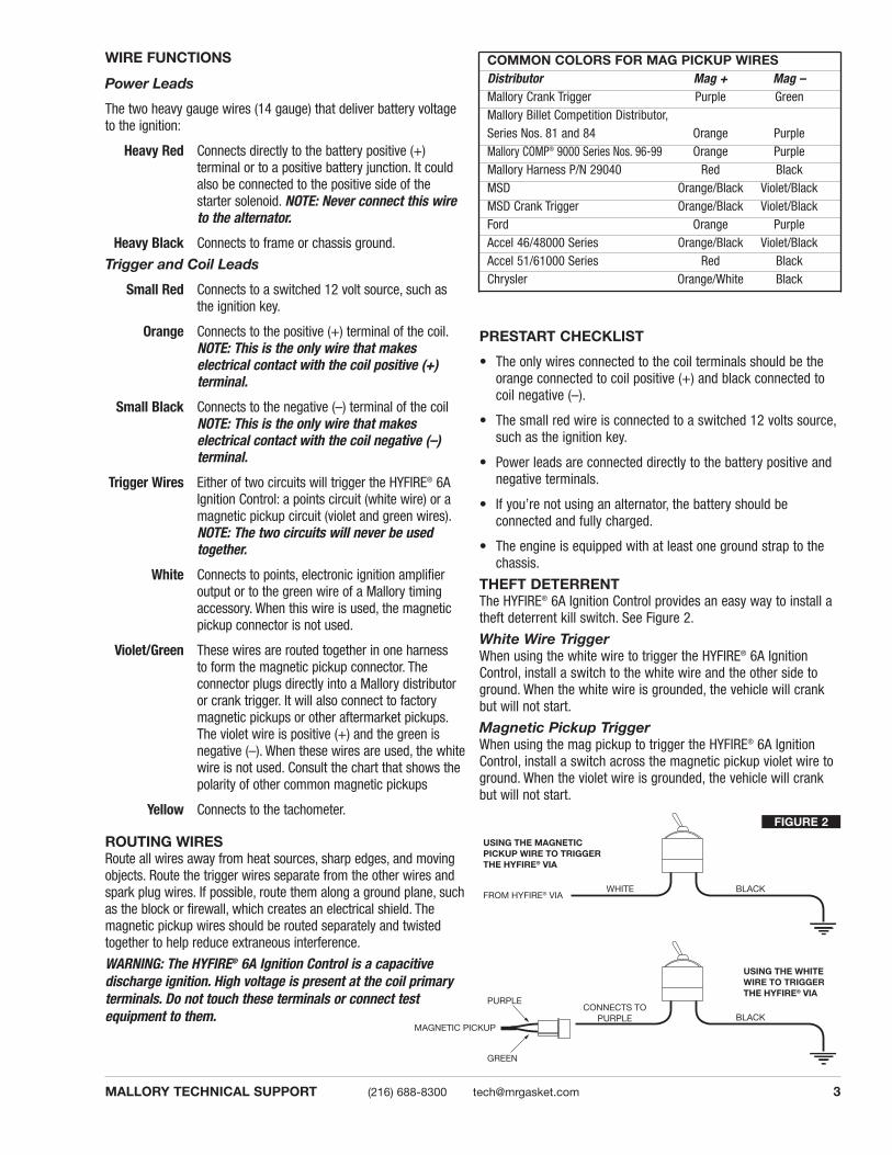
COMMON COLORS FOR MAG PICKUP WIRESDistributor Mag + Mag –Mallory Crank Trigger Purple GreenMallory Billet Competition Distributor,Series Nos. 81 and 84 Orange PurpleMallory COMP® 9000 Series Nos. 96-99 Orange PurpleMallory Harness P/N 29040 Red BlackMSD Orange/Black Violet/BlackMSD Crank Trigger Orange/Black Violet/BlackFord Orange PurpleAccel 46/48000 Series Orange/Black Violet/BlackAccel 51/61000 Series Red BlackChrysler Orange/White Black
WIRE FUNCTIONS
Power Leads
The two heavy gauge wires (14 gauge) that deliver battery voltageto the ignition:
Heavy Red Connects directly to the battery positive (+) terminal or to a positive battery junction. It couldalso be connected to the positive side of thestarter solenoid. NOTE: Never connect this wireto the alternator.
Heavy Black Connects to frame or chassis ground.
Trigger and Coil Leads
Small Red Connects to a switched 12 volt source, such asthe ignition key.
Orange Connects to the positive (+) terminal of the coil.NOTE: This is the only wire that makes electrical contact with the coil positive (+) terminal.
Small Black Connects to the negative (–) terminal of the coilNOTE: This is the only wire that makes electrical contact with the coil negative (–) terminal.
Trigger Wires Either of two circuits will trigger the HYFIRE® 6AIgnition Control: a points circuit (white wire) or amagnetic pickup circuit (violet and green wires).NOTE: The two circuits will never be usedtogether.
White Connects to points, electronic ignition amplifieroutput or to the green wire of a Mallory timing accessory. When this wire is used, the magneticpickup connector is not used.
Violet/Green These wires are routed together in one harness to form the magnetic pickup connector. The connector plugs directly into a Mallory distributoror crank trigger. It will also connect to factorymagnetic pickups or other aftermarket pickups.The violet wire is positive (+) and the green isnegative (–). When these wires are used, the whitewire is not used. Consult the chart that shows thepolarity of other common magnetic pickups
Yellow Connects to the tachometer.
ROUTING WIRESRoute all wires away from heat sources, sharp edges, and movingobjects. Route the trigger wires separate from the other wires andspark plug wires. If possible, route them along a ground plane, suchas the block or firewall, which creates an electrical shield. Themagnetic pickup wires should be routed separately and twistedtogether to help reduce extraneous interference.
WARNING: The HYFIRE® 6A Ignition Control is a capacitive discharge ignition. High voltage is present at the coil primaryterminals. Do not touch these terminals or connect test equipment to them.
PRESTART CHECKLIST
• The only wires connected to the coil terminals should be theorange connected to coil positive (+) and black connected tocoil negative (–).
• The small red wire is connected to a switched 12 volts source,such as the ignition key.
• Power leads are connected directly to the battery positive andnegative terminals.
• If you’re not using an alternator, the battery should be connected and fully charged.
• The engine is equipped with at least one ground strap to thechassis.
THEFT DETERRENTThe HYFIRE® 6A Ignition Control provides an easy way to install atheft deterrent kill switch. See Figure 2.
White Wire TriggerWhen using the white wire to trigger the HYFIRE® 6A Ignition Control, install a switch to the white wire and the other side toground. When the white wire is grounded, the vehicle will crankbut will not start.
Magnetic Pickup TriggerWhen using the mag pickup to trigger the HYFIRE® 6A IgnitionControl, install a switch across the magnetic pickup violet wire toground. When the violet wire is grounded, the vehicle will crankbut will not start.
FIGURE 2

FOR EARLY GM VEHICLESATTACH DIODE TO#4 TERMINAL
FOR FORD VEHICLESATTACH DIODE TO
#1 TERMINAL
1A-100V DIODE
TO CHARGING LIGHT
SPLICE HERE
DELCOTRONALTERNATOR
1A-100V DIODE
TO CHARGING LIGHT
SPLICE HERE
SMALL REDFROM HYFIRE® VIA
12 VOLTIGNITION SWITCH
CHRYSLER DUAL BALLAST RESISTOR
WHITE WIRE FROM HYFIRE® VIA
FROM POINTS OR AMPLIFIER
MALLORY IGNITION www.malloryperformance.com4
TACHOMETER COMPATIBILITY LISTAftermarket White Wire Magnetic TriggerTachometer Trigger ConnectorAutogage 29074 29078Autometer — —Ford Motorsport — —Moroso — —Stewart 29074 29078S.W. & Bi Torx — —Sun 29074 29078VDO 8910 29078AMC (Jeep) 29074 29078Chrysler 29074 29078Ford (Before 1976) 29074 29078Ford (After 1976) 29074 29078GM Bypass in-line Bypass in-line
filter filterImports 29074 29078
TROUBLESHOOTINGThis section offers several tests and checks you can perform to ensureproper installation and operation of the HYFIRE® 6A Ignition Control. Ifyou experience a problem with your HYFIRE® 6A, first check for properinstallation and poor connections. You can eliminate many problemsby checking these items. If you have any questions concerning yourHYFIRE® 6A Ignition Control contact the Mallory Technical Service Department at 775-882-6600, Monday through Friday, 8:00 am to5:00 pm Pacific time.
Tach/Fuel AdaptersIf your tachometer does not operate correctly, you probably need aMallory tach adapter. Consult the Tachometer Compatibility List at right for common tachometers and compatible tach adapters.
No-Run on Foreign VehiclesSome foreign vehicles with fuel injection systems may require a tachometer/fuel injection adapter to run with the HYFIRE® 6A IgnitionControl. Often, the same trigger source is used to operate an ignition,tachometer, and fuel injection. This results in a voltage signal that istoo low to trigger the fuel injection. A tach/fuel injection adapter willusually solve this problem.
Inoperative TachometersIf your tachometer fails to operate with the HYFIRE® 6A installed, youmay need a Mallory tach adapter. Before purchasing a tach adapter,try connecting your tachometer trigger wire to the yellow wire of theHYFIRE® 6A Ignition Control. This output produces a 12 volt, squarewave. If the tach still does not operate, you will need a tach adapter.Two different tach adapters are available:
PN 29078 If you are using the magnetic pickup connector (greenand violet wires) to trigger the HYFIRE® 6A, you willneed this adapter.
PN 29074 If your tach was triggered from the coil negative terminal (voltage trigger) and you are suing the whitewire to trigger the HYFIRE® 6A, you will need thisadapter.
Ballast ResistorIf you have a current trigger tach (originally connected to coil (+) positive) and use the white wire of the HYFIRE® 6A for triggering, youcan purchase a Chrysler Dual Ballast Resistor (1973-76 applications).Wire it as shown in Figure 3.
Engine Run-OnIf your engine continues to run even when the ignition is turned off,you are experiencing engine run-on. Usually, older vehicles with anexternal voltage regulator are susceptible to this condition. Becausethe HYFIRE® 6A Ignition Control receives power directly from the battery, it does not require much current to keep the unit energized.If you are experiencing run-on, it is due to a small amount of voltagegoing through the charging lamp indicator and feeding the small redwire (even if the key is turned off).
GM 1973-83 with Delcotron AlternatorsGM Delcotron alternators use an internal voltage regulator. Install thediode inline on the smallest wire exiting the alternator (see Figure 5).It is usually a brown wire.
Most other applications: To eliminate run-on, place a resistor in-line tothe HYFIRE® 6A small red wire to keep voltage from leaking into theHYFIRE® 6A Ignition.
FIGURE 3
Early Ford and GM: To solve the run-on problem, a diode is suppliedwith the HYFIRE® 6A Ignition Control. By installing this diode in-line ofthe wire that goes to the charging indicator, the voltage is blockedfrom entering the HYFIRE® 6A Ignition Control. Figure 4 shows theproper diode installation for early Ford and GM vehicles.
NOTE: Diodes are used to allow voltage to flow only one way.Make sure the diode is installed facing the proper direction, asshown in Figure 4.
Ford: Install the diode inline to the wire going to the #1 terminal.GM: Install the diode inline to the wire going to the #4 terminal.
FIGURE 4
FIGURE 5

5MALLORY TECHNICAL SUPPORT (216) 688-8300 [email protected]
Misses and Internittent ProblemsExperience has shown that if your engine is misfiring or hesitating at higher RPM, it is usually not an ignition problem. Most common causes include a coil or plug wire failure, arcing from the cap or boot plug to ground or spark ionization inside the cap. Perform the following checks:
• Inspect the plug wires at the cap and at the spark plug for a tightconnection. Visually inspect for cuts, abrasions, or burns.
• Inspect the primary coil wire connections. Because the HYFIRE® 6AIgnition Control receives a direct 12 volt source from the battery,there will not be any voltage at the coil positive (+) terminal, evenwith the key turned on. During cranking, or while the engine is running, very high voltage will be present and no test equipmentshould be connected.
WARNING: Do not touch the coil terminals during cranking orwhile the engine is running.
• Make sure that the battery is fully charged and the connections are clean and tight. If you are not running an alternator, this is animperative check. If the battery voltage drops below 10 volts duringa race, the HYFIRE® 6A Ignition Control output voltage will drop.
• Is the engine running lean? Inspect the spark plugs and the entirefuel system.
• Check all wiring connections for corrosion or damage. Remember to use proper connections followed by soldering, then seal the connections completely.
If everything checks positive, use the procedure below to test the ignition for spark. Mallory also offers an Ignition Tester (PN 28357) thatallows you to check the entire ignition system while it is installed inthe vehicle. This tool also checks operation of RPM limits, activatedswitches, and shift lights.
CHECKING FOR SPARK
If triggering the ignition with the white wire:
(See Figure 6)
1. Make sure the ignition switch is in the “OFF” position.
2. Remove the coil wire from the distributor cap and set the terminal approximately 1/4" from ground.
3. Disconnect the HYFIRE® 6A Ignition Control white wire from thedistributor’s points or ignition amplifier.
4. Turn the ignition to the “ON” position. Do not crank the engine.
5. Tap the white wire to ground several times. Each time you pullthe wire from ground, a spark should jump from the coil wire toground. If spark is present, the ignition is working properly. Ifthere is no spark, skip to Step 6 below.
If Triggering With the Magnetic Pickup:
(See Figure 7)
1. Make sure the ignition switch is in the OFF position.
2. Remove the coil wire from the distributor cap and set the terminal approximately 1/4" from ground.
3. Disconnect the HYFIRE® 6A Ignition Control magnetic pickupwires from the distributor.
4. Turn the ignition to the ON position. Do not crank the engine.
5. With a small jumper wire, short the HYFIRE® 6A Ignition Controlgreen and violet magnetic pickup wires together. Each time youbreak this short, a spark should jump from the coil wire toground. If spark is present, the ignition is working properly. Ifthere is no spark skip to Step 6 below.
6. If there is no spark.
A. Inspect all of the wiring.
B. Substitute another coil and repeat the test. If there is nowspark, the coil is at fault.
C. If there is still no spark, check to make sure there is 12 voltson the small red wire from the HYFIRE® 6A Ignition Controlwhen the key is in the ON position. If 12 volts is not present,find another switched 12 volts source and repeat the test.
D. If, after following the test procedures and inspecting all ofthe wiring, there is still no spark, the HYFIRE® 6A IgnitionControl is in need of repair. See the Warranty and Servicesection for information.
JUMPER WIRE
GREEN
VIOLET
FIGURE 7
TO GROUND
WHITEWIRE
FIGURE 6
The illustrations on the following pages show thebest way to install the HYFIRE® 6A Ignition Controlon various applications. If you have any problemsor questions while installing this device on your vehicle, contact the Mallory Technical ServiceDepartment at (775) 882-6600, 8:00 AM to 5:00 PMPacific time, or email [email protected].
®
PART No. 6852
R
BLACK (SMALLER)
ORANGE
YELLOW
COIL
WHITE
GREEN
PURPLE
RED (SMALL 18 GA)
BLACK (LARGE 14 GA)
RED (LARGE 14 GA)
TO BATTERY NEG (-)
TO BATTERY POS (+)
ORIGINAL COIL (+)
IGNITION KEY
NOT USED
TO 12 VOLTS
TO TACHOMETER
FROM MAG PICK-UP DISTOR CRANK TRIGGER
®
PART No. 6852
R
IGNITION KEY TO 12 VOLTS
BLACK (SMALLER)
ORANGE
YELLOW
COIL
WHITEGREEN
BROWN
RED (SMALL 18 GA)
TO TACHOMETER
BLACK (LARGE 14 GA)TO BATTERY NEG (-)
RED (LARGE 14 GA)TO BATTERY POS (+)
RED
TO ENGINE
CONNECT WIRES AT THESE POINTS
NOT USED
GREEN
PURPLE
®
PART No. 6852
R
BLACK (SMALLER)
ORANGE
YELLOW
COIL
WHITEOriginal coil wire from points or electronic ignition amplifier
RED
BLACK (LARGER)
RED (LARGER)
TO BATTERY NEG (-)
TO BATTERY POS (+)
IGNITION KEY TO 12 VOLTS
TO TACHOMETER
MAGNETIC PICK-UP(NOT USED)
Originally connected to coil (+)
MALLORY IGNITION www.malloryperformance.com6
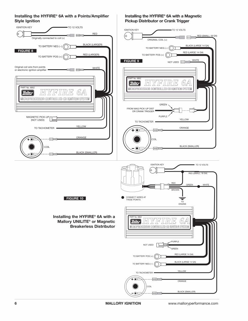
Installing the HYFIRE® 6A with a MagneticPickup Distributor or Crank Trigger
Installing the HYFIRE® 6A with aMallory UNILITE® or Magnetic
Breakerless Distributor
Installing the HYFIRE® 6A with a Points/AmplifierStyle Ignition
FIGURE 8
FIGURE 9
FIGURE 10
HHYYFFIIRREE 66AAHHYYFFIIRREE 66AA
HHYYFFIIRREE 66AA
®
PART No. 6852
R
BLACK (SMALLER)
ORANGE
YELLOW
COIL
WHITENOT USED
REDORIGINAL COIL (+)
IGNITION KEY TO 12 VOLTS
TO TACHOMETER
RED (LARGE 14 GA)TO BATTERY POS (+)
BLACK (LARGE 14 GA)TO BATTERY NEG (-)
GREEN
PURPLE
7MALLORY TECHNICAL SUPPORT (216) 688-8300 [email protected]
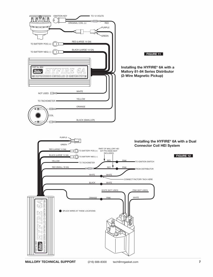
Installing the HYFIRE® 6A with aMallory 81-84 Series Distributor (2-Wire Magnetic Pickup)
®
PA
RT
No.
685
2
R
PART OF MALLORY HEI KIT P/N 29008 (NOT
INCLUDED)
YELLOW
WHITE WHITE
BLACK WHITE
WHITE (NOT USED)
SPLICE WIRES AT THESE LOCATIONS
PINK (NOT USED)
CONNECT FACTORY TACH HERE
FROM DISTRIBUTOR
TO IGNITION SWITCH
WHITE
GREEN
PURPLE
RED (SMALL 18 GA)
BLACK (LARGE 14 GA)
RED (LARGE 14 GA)
RED
RED
PINK
PINKORANGE
PINK
TO BATTERY NEG (-)
TO BATTERY POS (+)
TO TACHOMETER
Installing the HYFIRE® 6A with a DualConnector Coil HEI System
FIGURE 11
FIGURE 12
HHYYFFIIRREE 66AA
HHYY
FFIIRR
EE 66
AA

MALLORY IGNITION www.malloryperformance.com8
There are three different large cap HEI distributors. To identify whichof the following diagrams fit your specific application, remove thedistributor cap and rotor and locate the ignition module at the baseof the distributor. Count the number of terminals on both ends of themodule and follow the corresponding diagram. GM used 4, 5, and 7-pin modules in these distributors.
NOTE: Some 5-pin modules may experience a hesitation or stall ondeceleration. If this occurs, contact the Mallory Technical Service Department for the required bolt-in diode to correct the problem.
4-Pin Module 5-Pin Module
®
PART No. 6852
R
WHITE
RED (SMALL 18 GA)
NOT USED
YELLOWTO TACHOMETER
BLACK (LARGE 14 GA)TO BATTERY NEG (-)
RED (LARGE 14 GA)TO BATTERY POS (+)
BLACK (SMALL 18 GA TO Cñ)
ORANGE (TO B+)
PURPLE
GREEN
WHITE
GREEN
TO ENGINE GROUND
WHITE JUMPER
KEY CONNECTOR
HEAVY RED OR PINK WIRE FROM CAR WIRING HARNESS
GREEN
PURPLE
PART OF MALLORY HEI KIT P/N 29008 (NOT INCLUDED)
PART OF MALLORY HEI KIT P/N 29008 (NOT INCLUDED)
TO TACH
BLACK (LARGE 14 GA)TO BATTERY NEG (–)
RED (LARGE 14 GA)TO BATTERY POS (+)
®
PART No. 6852
R
YELLOWTO TACHOMETER
BLACK (SMALL 18 GA TO Cñ)
ORANGE (TO B+)
TO ENGINE GROUND
NOT USED
RED (SMALL 18 GA)
WHITE
RED JUMPER
WHITE JUMPER
HEAVY PINK OR RED FROM VEHICLE WIRE HARNESS
GREEN
PURPLE
PART OF MALLORY HEI KIT P/N 29008 (NOT INCLUDED)
PART OF MALLORY HEI KIT P/N 29008 (NOT INCLUDED)
PART OF MALLORY HEI KIT P/N 29008 (NOT INCLUDED)
Installing the HYFIRE® 6A with an HEI4-Pin Module (Magnetic Pickup Trigger)
Installing the HYFIRE® 6Awith an HEI 5-Pinor 7-Pin Module(Amplifier Trigger)
7-Pin Module
FIGURE 13
FIGURE 14
FIGURE 15
HHYYFFIIRREE 66AA
HHYYFFIIRREE 66AA

BLACK (LARGE 14 GA) TO BATTERY NEG (-)
RED (LARGE 14 GA)TO BATTERY POS (+)
®
PART No. 6852
R
MAGNETIC PICKUPNOT USED
WHITE
RED (SMALL 18 GA)
RED JUMPER
WHITE JUMPER
NOT USED (TAPE END)
ORANGEBLACK (SMALL 18 GA)
FROM DISTRIBUTORPINK
BROWN
HEAVY PINK, ORANGE, OR RED WIRE
GREEN
PURPLE
PART OF MALLORY HEI KIT P/N 29008 (NOT INCLUDED)
®
PART No. 6852
R
BLACK (SMALL 18GA)
ORANGE
YELLOW
GREEN
COIL
TO TACHOMETER
BLACK (LARGE 14GA)
RED (LARGE 14GA)
PURPLE
TO BATTERY NEG (-)
TO BATTERY POS (+)
MAGNETIC PICK-UP(NOT USED)
GREEN
RED
WHITE(SMALL 18 GA)
RED (SMALL 18 GA)
9MALLORY TECHNICAL SUPPORT (216) 688-8300 [email protected]
Installing the HYFIRE® 6A with anExternal 4-Terminal Coil (SingleConnector)
Installing the HYFIRE® 6A witha Ford Duraspark using theWhite Wire Trigger
FIGURE 16
FIGURE 17
HHYYFFIIRREE 66AA
HHYYFFIIRREE 66AA

®
PART No. 6852
R
BLACK (SMALL 18GA)ORANGE
YELLOWTO TACHOMETER
BLACK (LARGE 14GA)
INSULATE UNUSED ENDS OF JUMPERS
TO BATTERY NEG (-)
RED (LARGE 14GA)TO BATTERY POS (+)
WH
ITE
RE
D (S
MA
LL 1
8GA
)
GREEN
PURPLEMAGNETIC PICK-UP
(NOT USED)
RED
WHITE
PART OF MALLORY HEI KIT P/N 29008 (NOT INCLUDED)
®
PART No. 6852
R
YELLOWTO TACHOMETER
BLACK (LARGE 14 GA)TO BATTERY NEG (-)
RED (LARGE 14 GA)TO BATTERY POS (+)
GREEN
PURPLEMAGNETIC PICK-UP
(NOT USED)
WHITERED
BLACK
ORANGE
GREENRED
BLACK
YELLOW
ADAPTER/HARNESS P/N 29062(NOT INCLUDED)
YELLOW BLACK
FACTORY HARNESS PLUG (ORIGINALLY CONNECTED TO THE COIL)
RED GREEN
MALLORY IGNITION www.malloryperformance.com10
Installing the HYFIRE® 6Awith a Ford TFI(Without Harness)
Installing the HYFIRE® 6Awith a Ford TFI(With Harness)
FIGURE 18
FIGURE 19
HHYYFFIIRREE 66AA
HHYYFFIIRREE 66AA

®
PART No. 6852
R
BLACK (SMALL 18 GA)
ORANGE
BLACK/GRAY OR GRAY
YELLOWTO TACHOMETER
RED (LARGE 14 GA)TO BATTERY POS (+)
BLACK (LARGE 14 GA)TO BATTERY NEG (-)
WHITE
ORIGINAL COIL (+)
GREEN
PURPLE
GREEN/ORANGE
RED (SMALL 18 GA)GREEN/ORANGE
IGNITION TO 12 VOLTS
MAGNETIC PICKUPNOT USED
BLACK/GRAYFROM POINTS OR ELECTRONIC IGNITION
ORIGINAL COIL (-)
®
PART No. 6852
R
BLACK (SMALL 18 GA)
ORANGE
COIL
WHITENOT USED
YELLOWTO TACHOMETER
RED (LARGE 14 GA)TO BATTERY POS (+)
BLACK (LARGE 14 GA)TO BATTERY NEG (-)
RED (SMALL 18 GA)FROM ORIGINAL COIL
BLACK
ORANGE
CHRYSLER MODULE
VIOLET GREEN
GREEN
PURPLE6 FT EXTENSION CABLECUT ONE END ANDSPLICE AS SHOWN
SPLICE
11MALLORY TECHNICAL SUPPORT (216) 688-8300 [email protected]
Installing the HYFIRE® 6A with a Chrysler Electronic Ignition usinga Magnetic Pickup Trigger
Installing the HYFIRE® 6A with a LateModel Dodge (with 2-Pin Connector)
FIGURE 20
FIGURE 21
HHYYFFIIRREE 66AA
HHYYFFIIRREE 66AA

®
PART No. 6852
R
YELLOWTO TACHOMETER
RED (LARGE 14 GA)TO BATTERY POS (+)
BLACK (LARGE 14 GA)TO BATTERY NEG (-)
GREEN
PURPLE
RED (SMALL 18 GA)
MAGNETIC PICKUPNOT USED
ORIGINAL COIL (+) WIRE
SPLICE HERE
WHITE
(-) BLACK (SMALL 18 GA)
AMPLIFIER
ORIGINAL COIL (-) TERMINAL FROM
AMPLIFIER
TO IGNITION SWITCH
(+) ORANGE
SPLICE HERE
MALLORY IGNITION www.malloryperformance.com12
Installing the HYFIRE® 6A witha Typical Import Application
FORM 1522TLMade in U.S.A.
Printed in U.S.A.
MALLORY IS A DIVISION OF PRESTOLITE PERFORMANCE(216) 688-8300
RPM LIMITER SETTINGSNote the sticker attached to the end plate of the HYFIRE® 6-AL.This sticker shows settings for number of cylinders and RPM limits. In case the sticker becomes damaged or otherwise unreadable, the settings are shown at right.
Setting Switch #4This switch must remain in the down position for normal operation. CAUTION: Using the Mallory HYFIRE® 6-AL (6AL) withswitch #4 in the up position could cause ignition damage.
Rotary Switch Switch #1 Switch #1Position DOWN UP
0 4,500 8,5001 4,750 8,7502 5,000 9,0003 5,250 9,2504 5,500 9,5005 5,750 9,7506 6,000 10,0007 6,250 10,2508 6,500 10,5009 6,750 10,750A 7,000 11,000B 7,250 11,250C 7,500 11,500D 7,750 11,750E 8,000 12,000F 8,250 NO LIMIT
Number ofCylinders Switch #2 Switch #3
4 UP Down6 Down UP8 Down Down
FIGURE 22
FIGURE 23
HHYYFFIIRREE 66AA

13MALLORY TECHNICAL SUPPORT (216) 688-8300 [email protected]
CONTROL DE ARRANQUE ELECTRÓNICOHYFIRE® SERIES 6-A y 6-AL
NÚMEROS DE PIEZAS 6852M (6-A) y 6853M (6-AL)
INSTRUCCIONES DE INSTALACIÓNFORM 1522TL
INFORMACIÓN GENERALLas características del HYFIRE® 6-A y HYFIRE® 6-AL son idénticas,excepto: HYFIRE® 6-AL incluye un circuito limitador de RPM de una fase. Se pueden establecer varios límites de RPM medianteinterruptores que se acceden mediante la sección rectangularrecortada en el soporte terminal. Vea la página 12 de estas instrucciones para obtener información adicional sobre las características de limitación de revoluciones del HYFIRE® 6-AL.BateríaEl control de arranque serie HYFIRE®6A funciona en cualquier sistema eléctrico de 12 voltios con tierra negativa que tenga distribuidor. También funciona con baterías de 16 voltios y puedesoportar picos momentáneos de 24 voltios en caso de arranquescon conexión en puente provisional. Este sistema proporciona elvoltaje completo con suministro de 10 a 18 voltios y funciona conun voltaje de suministro de hasta 8 voltios.Si su aplicación no utiliza alternador, debe dejar por lo menos 15amperios/hora por cada media hora de funcionamiento. Si el motorgira con la misma batería que utilizan otros accesorios, tales comouna bomba eléctrica de combustible o agua, aumente la capacidadde amperios/hora.BobinasPara obtener el rendimiento óptimo con el control de arranqueHYFIRE® 6A, se recomienda el uso de la bobina Mallory PROMASTER®, número de pieza 29440 o 30440. También se puedeutilizar la bobina Mallory PROMASTER®, número de pieza 29625,como también la mayoría de las bobinas originales o de repuesto diseñadas para reemplazar las originales.NOTA: No utilice la bobina Mallory PROMASTER®, número depieza 28880.TacómetrosEl cable amarillo del control de arranque HYFIRE® 6A proporcionauna señal de disparador para los tacómetros, luces de cambios yotros dispositivos adicionales activados por las RMP. Este cablegenera una señal de onda cuadrada de 12 voltios con un ciclo detrabajo del 20%.Algunos vehículos con tacómetros instalados en fábrica puedenrequerir un adaptador de tacómetro para utilizar el control dearranque HYFIRE® 6A. Si su vehículo GM utiliza un filtro en línea,éste puede hacer que el tacómetro baje a cero al acelerar. Si estosucede, derive el filtro. Para obtener más información sobre el usode tacómetros, consulte la página 4.
BujíasEl uso de las bujías y extensión térmica apropiadas es importantepara obtener el rendimiento óptimo. Debido a la cantidad de variables que se deben considerar, sugerimos que comience por lasbujías recomendadas por el fabricante de su motor. Luego puedeexperimentar con leves modificaciones en la calibración de lasbujías y la extensión térmica para obtener el mejor rendimiento delmotor. Utilice el gráfico a la derecha como punto inicial. También serecomienda el uso de bujías sin resistor.Vehículos extranjerosDebido a los sistemas de inyección de combustible modernos,algunos vehículos extranjeros pueden requerir un adaptador detacómetro/inyección de combustible para utilizar el control dearranque HYFIRE® 6A.NOTA: No instale el control de arranque HYFIRE® 6A en ningúnvehículo que originalmente viene equipado con un control de arranque de CD.Bujías y cablesLos cables de alta calidad y bobinados en espiral, y el cableadoapropiado son fundamentales para el funcionamiento del control dearranque HYFIRE® 6A. Este tipo de cable proporciona una buenaruta para la chispa y al mismo tiempo minimiza la interferenciaelectromagnética (EMI, por sus siglas en ingles).NOTA: No utilice cables para bujías con núcleos sólidos con elcontrol de arranque HYFIRE® 6A.Colocación del cableadoLos cables se deben colocar lejos de los bordes agudos, objetos enmovimiento y fuentes de calor. Se deben separar los cables queestán al lado de otros cables en el orden de encendido del motor.Por ejemplo, en los motores Chevy V8 con orden de encendido 1-8-4-3-6-5-7-2, los cilindros 5 y 7 están ubicados uno al lado delotro en el motor y en el orden de encendido. El voltaje del cable 5podría saltar al cable 7. Esto podría ocasionar detonaciones yaverías en el motor. Para obtener protección adicional contra lainterferencia, Mallory cuenta con el forro aislado PRO SHIELD. ProShield es un forro protector de tejido de vidrio y revestido de silicónque se desliza sobre los cables de las bujías. También ayuda areducir los daños producidos por el calor y los objetos agudos.
1 Control de arranque HYFIRE® 6A4 Tornillos para hoja metálica Nº 102 Amarres para cables2 Terminales de anillo, aislados1 Diodo de 1 amperio/100 voltios2 Terminales de lengüeta de 6,35 mm (1/4 de pulg.)
5 Disyuntores macho de 6,35 mm (1/4 de pulg.)5 Disyuntores hembra de 6,35 mm (1/4 de pulg.)1 Ojal de goma2 Abrazaderas para cables1 Extensión del circuito de absorción magnética
PIEZAS INCLUIDAS:

MALLORY IGNITION www.malloryperformance.com14
Cuando consiga una ubicación apropiada para montar la unidad,asegúrese de que los cables del arranque alcancen las conexiones.Sujete el arranque en su sitio y marque la posición de los agujerosde montaje. Utilice una broca de 3,175 mm (1/8 de pulg.) para taladrar los agujeros. Utilice los tornillos autorroscantes suministrados para montar la caja.
CABLEADOLargo de los cablesTodos los cables del control de arranque HYFIRE® 6A se puedenacortar con tal que se utilicen o suelden conectores de calidad en el sitio. Para alargar los cables, utilice cable de un calibre superior(calibre 12 para los cables de energía, calibre 16 para los demáscables). Utilice los conectores apropiados para terminar todos loscables. Todas las conexiones se deben soldar y sellar.
Conexiones a tierraLa conexión indebida a tierra puede ocasionar muchos problemasfrustrantes. Cuando se deba conectar un cable específico a tierra,conéctelo al chasis. Siempre conecte una correa de conexión a tierra entre el motor y el chasis. Conecte todos los cables de conexión a tierra a una superficie metálica que esté limpia y sinpintura.
Resistor de balastoSi su vehículo cuenta con un resistor de balasto en línea con elcableado de la bobina, no será necesario derivarlo. Esto se debe aque el control de arranque HYFIRE® 6A recibe la energía principaldirectamente de la batería.
INFORMACIÓN MISCELÁNEASelladoNo intente sellar el control de arranque HYFIRE® 6A. Todos los circuitos del HYFIRE® 6A reciben un revestimiento de conformaciónde sellador que protege los componentes electrónicos de lahumedad. Al sellar el HYFIRE® 6A no permitirá que la humedad quepenetra en los ojales salga, lo que puede resultar en corrosión.
SoldaduraPara evitar averiar el control de arranque HYFIRE® 6A, al soldaralguna pieza del vehículo desconecte los cables de energía positivo(rojo) y negativo (negro) del control de arranque HYFIRE® 6A.También es aconsejable desconectar el cable de conexión a tierradel tacómetro.
Tapa del distribuidor y rotorSe recomienda la instalación de una nueva tapa del distribuidor yrotor al instalar el control de arranque HYFIRE® 6A. Asegúrese deque la tapa esté limpia por dentro y por fuera, especialmente lasterminales y la punta del rotor. Es posible que en los vehículos contapas pequeñas, el aire dentro de éstas se cargue con electricidady ocasione interferencia que puede resultar en fallas del encendido.Puede evitar que esto suceda taladre dos agujeros de ventilación en la tapa. Taladre los agujeros entre las terminales a la altura delrotor, en el lado opuesto de la toma. Si se requiere, ponga un trozopequeño de malla sobre los agujeros para que sirva de filtro.
LED de diagnósticos del Hyfire® 6AEn el panel terminal del control de arranque Hyfire® 6A hay un agujero pequeño. Detrás del agujero está un indicador LED rojo.Éste cumple dos funciones: cuando enciende por primera vez elinterruptor del arranque el LED parpadeará rápidamente 3 veces.Esto indica que el sistema de arranque tiene energía y que elmicroprocesador funciona debidamente. Además, el LEDparpadeará cuando reciba la señal apropiada de disparador delvehículo. Si luego del encendido normal el LED no parpadea al girar el motor, deberá verificar el circuitodisparador para ver si tiene problemas. Si elLED parpadea cuando gira el motor, pero nohay chispa, el problema está en otro sitio.
Selección de cilindro para elHyfire® 6AEl control de arranque HYFIRE® 6A viene configurado de la fábrica para el funcionamiento con 8 cilindros. Si deseautilizar este arranque con un motor de 4 ó 6cilindros, primero debe quitar los cuatrotornillos que sujetan la placa terminal que tieneel agujero LED. Cuando quite la placa terminal, veráel extremo de la tarjeta de circuito. Busque el interruptorde dos secciones. Para seleccionar el modo de 4 cilindros,ponga el interruptor marcado "1" en la posición "ON". Para seleccionar el modo de 6 cilindros, ponga el interruptor marcado"2" en la posición "ON". Si ambos interruptores están en la posición "OFF" o en "ON", el arranque funcionará en el modo de 8cilindros. Consulte la figura 1.
MONTAJEEl control de arranque HYFIRE® 6A se puede montar en cualquierposición. Si lo monta en el compartimiento del motor, manténgaloalejado de los objetos en movimiento y las fuentes de calor. Nomonte la unidad en un sitio cerrado, como en la guantera.
LABELS FOR "CYLINDER SELECT" ON CIRCUIT BOARD
DIAGNOSTIC LED
FIGURA 1
LED DE DIAGNÓSTICOS
ETIQUETAS PARA "SELECCIÓN
DE CILINDRO" EN LA TARJETA DE
CIRCUITOS

15MALLORY TECHNICAL SUPPORT (216) 688-8300 [email protected]
FROM HYFIRE® VIAWHITE BLACK
USING THE MAGNETIC PICKUP WIRE TO TRIGGER THE HYFIRE® VIA
USING THE WHITE WIRE TO TRIGGER THE HYFIRE® VIA
CONNECTS TO PURPLE BLACK
MAGNETIC PICKUP
PURPLE
GREEN
LISTA DE VERIFICACIÓN DE PREARRANQUE• Los únicos cables conectados a los terminales de la bobina
deben ser el naranja al terminal positivo (+) y el negro conectadoal terminal negativo (–).
• El cable rojo delgado se conecta a una fuente conmutada de 12 voltios, tal como la llave del encendido.
• Los cables de energía se conectan directamente a los terminalespositivo y negativo de la batería.
• Si no utiliza el alternador, la batería se debe conectar y cargartotalmente.
• El motor tiene por lo menos una correa de conexión a tierra conectada al chasis.
DISPOSITIVO ANTIRROBOSEl control de arranque HYFIRE® 6A proporciona una manera fácil de instalar un interruptor de apagado que sirve de dispositivoantirrobos. Consulte la figura 2.
Disparador de cable blanco Al utilizar el cable blanco para disparar el control de arranqueHYFIRE® 6A, instale un interruptor entre el cable blanco del circuitode absorción magnética y la tierra. Cuando el cable blanco seconecta a tierra, el motor del vehículo girará, mas no arrancará.
Disparador de circuito de absorción magnética Al utilizar el circuito de absorción magnética para disparar el control de arranque HYFIRE® 6A, instale un interruptor entre el cablevioleta y el otro lado a tierra. Cuando el cable violeta se conecta atierra, el motor del vehículo girará, mas no arrancará.
FIGURA 2
FUNCIONES DEL CABLEADOCables de energíaLos dos cables de calibre grueso (calibre 14) que trasmiten elvoltaje de la batería al arranque:
Rojo grueso Se conecta directamente al terminal positivo (+)de la batería o a un empalme positivo de labatería. También se puede conectar al lado positivo del solenoide del arranque.NOTA: Nunca conecte este cable al alternador.
Negro grueso Se conecta a la conexión a tierra del chasis.
Cables del disparador y bobinaRojo delgado Se conecta a una fuente conmutada de 12
voltios, tal como la llave del encendido.Naranja Se conecta al terminal positivo (+) de la bobina.
NOTA: Este es el único cable que hace contacto eléctrico con el terminal positivo (+)de la bobina.
Negro delgado Se conecta al terminal negativo (–) de la bobina.NOTA: Este es el único cable que hace contacto eléctrico con el terminal negativo (–)de la bobina.
Cables del Cualquiera de los dos circuitos disparará el control de arranque HYFIRE® 6A: un circuito depuntos (cable blanco) o un circuito de absorciónmagnética (cables violeta o verdes).NOTA: Nunca se utilizarán los dos circuitos almismo tiempo.
Blanco Se conecta a los puntos, a la salida del amplificador de arranque electrónico o al cableverde del accesorio de tiempos Mallory. Cuandose utiliza este cable, no se utiliza el conector deabsorción magnética.
Violeta/verde Estos cables se colocan juntos en un arnés paraformar el conector de absorción magnética.El conector se enchufa directamente en el distribuidor Mallory o disparador de giro delmotor. También se puede enchufar en los conectores de absorción magnética instalados enfábrica u otros conectores de repuesto. El cablevioleta es positivo (+) y el verde es negativo (–).Cuando se utilizan estos cables, no se utiliza elcable blanco. Consulte el gráfico que muestra lapolaridad de otros conectores de absorción magnética comunes.
Amarillo Se conecta al tacómetro.
COLOCACIÓN DEL CABLEADOColoque todos los cables lejos de las fuentes de calor, bordes agudos y objetos en movimiento. Separe los cables del disparadorde los otros cables, incluso los de las bujías. De ser posible,colóquelos a lo largo de un plano conectado a tierra, como elbloque del motor o la mampara cortafuegos, que crea un blindajeeléctrico. Los cables del circuito de absorción magnética debencolocarse por separado y se deben enroscar juntos para ayudar a reducir la interferencia excedente.ADVERTENCIA: El control de arranque HYFIRE® 6A es unarranque de descarga capacitiva. El voltaje alto se encuentraen los terminales principales de la bobina.No toque estos terminales ni conecte equipos de prueba en éstos.
Cables del disparador
COLORES COMUNES DE LOS CABLES DEL CIRCUITO DE ABSORCIÓN MAGNÉTICADistribuidor Mag + Mag –Disparador de giro del motor Mallory Morado VerdeDistribuidor de carrera de palanquilla Mallory,números de serie 81 y 84 Naranja MoradoMallory Comp® 9000 número de serie 96-99 Naranja MoradoArnés Mallory número de pieza 29040 Rojo NegroMSD Naranja/negro Violeta/negroDisparador de giro del motor MSD Naranja/negro Violeta/negroFord Naranja MoradoAccel serie 46/48000 Naranja/negro Violeta/negroAccel serie 51/61000 Rojo NegroChrysler Naranja/blanco Negro
USO DEL CABLE DEL CIRCUITO DE ABSORCIÓN MAGNÉTICAPARA DISPARAR ELHYFIRE® 6A
USO DEL CABLE BLANCOPARA DISPARAR EL
HYFIRE® 6A
DESDE EL HYFIRE® 6ABLANCO NEGRO
NEGRO
MORADO
CIRCUITO DE ABSORCIÓN MAGNÉTICA
SE CONECTA ALMORADO
VERDE

MALLORY IGNITION www.malloryperformance.com16
FOR EARLY GM VEHICLESATTACH DIODE TO#4 TERMINAL
FOR FORD VEHICLESATTACH DIODE TO
#1 TERMINAL
1A-100V DIODE
TO CHARGING LIGHT
SPLICE HERE
DELCOTRONALTERNATOR
1A-100V DIODE
TO CHARGING LIGHT
SPLICE HERESMALL RED
FROM HYFIRE® VIA
12 VOLTIGNITION SWITCH
CHRYSLER DUAL BALLAST RESISTOR
WHITE WIRE FROM HYFIRE® VIA
FROM POINTS OR AMPLIFIER
LISTA DE COMPATIBILIDAD CON TACÓMETROTacómetro Disparador De Conector Del De Repuesto Cable Blanco Disparador MagnéticoAutogage 29074 29078Autometer — —Ford Motorsport — —Moroso — —Stewart 29074 29078S.W. & Bi Torx — —Sun 29074 29078VDO 8910 29078AMC (Jeep) 29074 29078Chrysler 29074 29078Ford (Before 1976) 29074 29078Ford (After 1976) 29074 29078GM Filtro de derivación Filtro de derivación
en línea en líneaImports 29074 29078
RESOLUCIÓN DE PROBLEMASEsta sección ofrece varias pruebas y verificaciones que puede realizarpara asegurar la instalación y funcionamiento apropiados del control dearranque HYFIRE® 6A. Si tiene problemas con el HYFIRE® 6A, primeroverifique que la instalación esté bien hecha o si hay conexiones inde-bidas. Puede solucionar muchos problemas verifi-cando estos elemen-tos. Si tiene preguntas sobre el control de arranque HYFIRE® 6A, pón-gase en contacto con el departamento de servicio técnico de Mallory(Mallory Technical Service Department), llamando al 775-882-6600, delunes a viernes, de 8:00 am a 5:00 pm (huso horario del Pacífico enEE.UU.).Adaptadores de tacómetro/combustibleSi el tacómetro no funciona debidamente, probablemente requiera unadaptador de tacómetro Mallory. Consulte la lista de compatibilidad delos tacómetros que está a la derecha para obtener los tacómetroscomunes y los adaptadores de tacómetro compatibles.No funcionan los vehículos extranjerosAlgunos vehículos extranjeros con sistemas de inyección de combustible pueden requerir un adaptador de tacómetro/inyección de combustible para utilizar el control de arranque HYFIRE® 6A.Frecuentemente se utiliza la misma fuente de disparador para hacer funcionar el arranque, tacómetro y sistema de inyección de com-bustible. Esto da como resultado una señal de voltaje demasiado bajapara disparar el sistema de inyección de combustible. El adaptador de tacómetro/inyección de combustible generalmente solu-ciona este problema.No funciona el tacómetroSi el tacómetro no funciona con el HYFIRE® 6A instalado, probable-mente requiere un adaptador de tacómetro Mallory. Antes de comprarel adaptador de tacómetro, intente conectar el cable del disparador detacómetro al cable amarillo del control de arranque HYFIRE® 6A. Estasalida produce una onda cuadrada de 12 voltios. Si el tacómetrotodavía no funciona debidamente, requerirá un adaptador detacómetro. Hay dos adaptadores de tacómetro distintos disponibles:Número de pieza 29078 Si utiliza el conector de absorción magnética
(cables verde y violeta) para disparar el HYFIRE® 6A, debe uti-lizar este adaptador.
Número de pieza 29074 Si el tacómetro se dispara del terminal negativo de la bobina (disparado por voltaje) y utiliza el cableblanco para disparar el HYFIRE® 6A, debe utilizar este adaptador.
Resistor de balastoSi tiene un tacómetro disparado por corriente (originalmente conectado al positivo (+) de la bobina) y utiliza el cable blanco delHYFIRE® 6A para disparar, puede comprar el resistor de doble balastoChrysler (aplicaciones de 1973 a 1976). Cabléelo como se muestra enla figura 3.Motor que continúa encendidoSi el motor continúa encendido con el arranque apagado, experi-mentauna falla que se denomina encendido continuo. Generalmente losvehículos más viejos con regulador de voltaje externo son más suscep-tibles a esta condición. Debido a que el control de arranque HYFIRE® 6Arecibe energía directamente de la batería, no se requiere mucha corri-ente para mantener la unidad energizada. Si el motor continúa encen-dido, se debe a una pequeña cantidad de voltaje que pasa por el indi-cador de la luz de carga que alimenta el cable rojo delgado (aún si lallave está apagada).
GM 1973 a 1983 con alternadores DelcotronLos alternadores GM Delcotron utilizan un regulador de voltaje interno. Instale el diodo en línea con el cable más delgado que sale delalternador (vea la figura 5). Por lo general el cable es marrón.La mayoría de las otras aplicaciones: Para eliminar el problema delmotor que continúa encendido, coloque un resistor en línea con elcable rojo delgado del HYFIRE® 6A para que el voltaje no se fugue alarranque HYFIRE® 6A.FIGURA 3
Modelos Ford y GM antiguos: Para solucionar el problema del motorque continúa encendido, se suministra un diodo con el control dearranque HYFIRE® 6A. Al instalar este diodo en línea en el cable que vaal indicador de carga, se bloquea el voltaje para que no entre al controlde arranque HYFIRE® 6A. La figura 4 muestra la instalación debida deldiodo para vehículos Ford y GM antiguos.
NOTA: Los diodos se utilizan para permitir que el voltaje fluya en una sola dirección. Asegúrese de que el diodo está instal-ado hacia la dirección apropiada, como se muestra en la figura 4.
Ford: Instale el diodo en línea con el cable que va al terminal 1.GM: Instale el diodo en línea con el cable que va al terminal 4.
FIGURA 4
FIGURA 5
INTERRUPTOR DE ARRANQUE DE 12 VOLTIOS
CABLE ROJO DELGADODESDE EL HYFIRE® 6A
DESDE LOS PUNTOSO AMPLIFICADOR
CABLE BLANCODESDE EL HYFIRE® 6A
RESISTOR DE DOBLEBALASTO CHRYSLER
PARA LOSVEHÍCULOS FORD,
CONECTE EL DIODOAL TERMINAL
NÚMERO 1
PARA LOS VEHÍCULOS GMANTIGUOS, CONECTE EL DIODOAL TERMINAL NÚMERO 4
HACIA LA LUZ DE CARGA
EMPALME AQUÍ
EMPALMEAQUÍ
DIODO DE 1A-100V
DIODO DE 1A-100V
ALTERNADORDELCOTRON
HACIA LA LUZ DE CARGA
VOLTAGEREGULATOR

17MALLORY TECHNICAL SUPPORT (216) 688-8300 [email protected]
Fallas y problemas intermitentesLa experiencia ha demostrado que si hay fallas del arranque delmotor o titubeo a RPM superiores, por lo general no es una falla dearranque. Entre las causas más comunes se incluyen las fallas dela bobina o cables de las bujías, arcos de la tapa o capuchón de labujía a tierra o ionización de la chispa dentro de la tapa. Lleve acabo las siguientes verificaciones:• Revise los cables de las bujías en la tapa y en las bujías para
asegurarse que la conexión sea segura. Haga una inspección ocular para ver si hay cortes, abrasiones o quemaduras.
• Inspeccione las conexiones del cable principal de la bobina.Debido a que el control de arranque HYFIRE® 6A recibe unafuente directa de 12 voltios de la batería, no habrá voltaje en elterminal positivo (+) de la bobina, aún con la llave encendida.Durante el giro del motor o cuando éste esté encendido, habráun voltaje muy alto presente, y no se debe conectar ningúnequipo de pruebas.
ADVERTENCIA: No toque los terminales de la bobina cuando elmotor gire o mientras esté encendido.• Asegúrese de que la batería esté totalmente cargada y que las
conexiones estén limpias y seguras. Si no utiliza un alternador,esta verificación es obligatoria. Si el voltaje de la batería cae pordebajo de los 10 voltios durante una carrera, el voltaje de salidadel control de arranque HYFIRE® 6A disminuirá.
• ¿El motor funciona de manera eficiente? Inspeccione las bujías ytodo el sistema de combustible.
• Verifique todas las conexiones del cableado para ver si tienen corrosión o están averiadas. Recuerde utilizar las conexionesapropiadas seguido por soldadura, luego selle las conexiones por completo.
Si todo está en regla, utilice el procedimiento a continuación paraprobar el arranque para ver si hay chispa. Mallory también cuentacon un probador de arranque (número de pieza 28357) que permite verificar todo el sistema de arranque, cuando éste seencuentra instalado en el vehículo. Esta herramienta también verifica el funcionamiento de los límites de RPM, interruptores activados y luces de cambios.
JUMPER WIRE
GREEN
VIOLET
FIGURA 7
TO GROUND
WHITEWIRE
FIGURA 6
VERIFICACIÓN DE CHISPASi se dispara el arranque con el cable blanco:(Consulte la figura 6)
1. Asegúrese de que el interruptor del arranque se encuentra en laposición "OFF".
2. Desconecte el cable de la bobina de la tapa del distribuidor yponga el terminal aproximadamente a 6,35 mm (1/4 de pulg.)de la conexión a tierra.
3. Desconecte el cable blanco del control de arranque HYFIRE® 6Ade los puntos del distribuidor o del amplificador del arranque.
4. Ponga el arranque en la posición "ON". No haga girar el motor.
5. Golpee ligeramente el cable blanco contra la conexión a tierravarias veces. Cada vez que retira el cable de la conexión a tierra,debe saltar una chispa del cable de la bobina a la conexión atierra. Si hay chispa, el arranque funciona debidamente. Si nohay chispa, vaya al paso 6 a continuación.
Si se dispara con el circuito de absorción magnética:(Consulte la figura 7)
1. Asegúrese de que el interruptor del arranque se encuentra en laposición "OFF".
2. Desconecte el cable de la bobina de la tapa del distribuidor yponga el terminal aproximadamente a 6,35 mm (1/4 de pulg.)de la conexión a tierra.
3. Desconecte los cables del circuito de absorción magnética delcontrol de arranque HYFIRE® 6A en el distribuidor.
4. Ponga el arranque en la posición "ON". No haga girar el motor.
5. Con un cable de puente corto, junte los cables verde y violetadel circuito de absorción magnética del control de arranqueHYFIRE® 6A para hacer un cortocircuito. Cada vez que elimina el cortocircuito, debe saltar una chispa del cable de la bobina la conexión a tierra. Si hay chispa, el arranque funciona debidamente. Si no hay chispa, vaya al paso 6 a continuación.
6. Si no hay chispa.
A. Inspeccione todo el cableado.
B. Sustituya la bobina y repita la prueba. Si ahora hay chispa,la bobina tiene fallas.
C. Si todavía no hay chispa, asegúrese de que el cable rojo delgado del control de arranque HYFIRE® 6A tenga suministro de 12 voltios cuando la llave está en la posiciónON. Si no hay suministro de 12 voltios, consiga otra fuente conmutada de 12 voltios y repita la prueba.
D. Si luego de seguir los procedimientos de prueba e inspeccionar todo los cables no hay chispa, se debe repararel control de arranque HYFIRE® 6A. Consulte la secciónGarantía y servicio técnico para obtener información.
Las ilustraciones en las siguientes páginas muestran la mejor forma de instalar el control dearranque HYFIRE® 6A en distintas aplicaciones. Si tiene problemas o preguntas al instalar este dispositivo en su vehículo póngase en contacto con el departamento de servicio técnico de Mallory(Mallory Technical Service Department), llamando al(775) 882-6600, de 8:00 am a 5:00 pm (huso horariodel Pacífico en EE.UU.), o enviando un mensaje decorreo electrónico a [email protected].
CABLEBLANCO
A TIERRA
CABLE DE PUENTE
6OLETA
VERDE

MALLORY IGNITION www.malloryperformance.com18
®
PART No. 6852
R
BLACK (SMALLER)
ORANGE
YELLOW
COIL
WHITE
GREEN
PURPLE
RED (SMALL 18 GA)
BLACK (LARGE 14 GA)
RED (LARGE 14 GA)
TO BATTERY NEG (-)
TO BATTERY POS (+)
ORIGINAL COIL (+)
IGNITION KEY
NOT USED
TO 12 VOLTS
TO TACHOMETER
FROM MAG PICK-UP DISTOR CRANK TRIGGER
®
PART No. 6852
R
IGNITION KEY TO 12 VOLTS
BLACK (SMALLER)
ORANGE
YELLOW
COIL
WHITEGREEN
BROWN
RED (SMALL 18 GA)
TO TACHOMETER
BLACK (LARGE 14 GA)TO BATTERY NEG (-)
RED (LARGE 14 GA)TO BATTERY POS (+)
RED
TO ENGINE
CONNECT WIRES AT THESE POINTS
NOT USED
GREEN
PURPLE
®
PART No. 6852
R
BLACK (SMALLER)
ORANGE
YELLOW
COIL
WHITEOriginal coil wire from points or electronic ignition amplifier
RED
BLACK (LARGER)
RED (LARGER)
TO BATTERY NEG (-)
TO BATTERY POS (+)
IGNITION KEY TO 12 VOLTS
TO TACHOMETER
MAGNETIC PICK-UP(NOT USED)
Originally connected to coil (+)
FIGURA 8
FIGURA 9
FIGURA 10
Instalación del HYFIRE® 6A con un distribuidor deabsorción magnética o disparador de giro del motor
Instalación del HYFIRE® 6A con arranque tipo pun-tos/amplificador
Instalación del HYFIRE® 6A con un distribuidor Mallory UNILITE® o
distribuidor sin cortacircuito magnético
LLAVE DEL ENCENDIDOLLAVE DEL ENCENDIDO
LLAVE DEL ENCENDIDO
Originalmente conectado al positivo (+) de la bobina
HACIA 12 VOLTIOSHACIA 12 VOLTIOS
HACIA 12 VOLTIOS
A NEG (–) DE LA BATERÍAA NEG (–) DE LA BATERÍA
A POS (+) DE LA BATERÍAA POS (+) DE LA BATERÍA
ROJO
NARANJA
NARANJA
NEGRO (MÁS GRUESO)
ROJO (MÁS GRUESO)
Cable original de la bobinadesde los puntos o amplificador
de arranque electrónico
CIRCUITO DE ABSORCIÓNMAGNÉTICA (NO SE UTILIZA)
AL TACÓMETRO
AL TACÓMETRO
A NEG (–) DE LA BATERÍA
A POS (+) DE LA BATERÍA
AL TACÓMETRO
AMARILLO
AMARILLO
NEGRO (MÁS DELGADO)
NEGRO (MÁS DELGADO)
NARANJA
AMARILLO
NEGRO (MÁS DELGADO)
BOBINA
BOBINA
BOBINA
BLANCO
BLANCO
BOBINA ORIGINAL (+)
ROJO (DELGADO DE CALIBRE 18)
ROJO (DELGADO DE CALIBRE 18)
NEGRO (GRUESO DECALIBRE 14)
ROJO (GRUESO DE CALIBRE 14)
ROJO (GRUESO DE CALIBRE 14)
NEGRO (GRUESO DE CALIBRE 14)
NO SE UTILIZA
NO SE UTILIZA
DESDE EL DISTRIBUIDOR DEABSORCIÓN MAGNÉTICA O DISPARADOR DE GIRO
MORADO
MORADO
VERDE
VERDE
MARRÓN
A TIERRADEL MOTOR
CONECTE LOS CABLESEN ESTOS PUNTOS
VERDEROJO BLANCO
HHYYFFIIRREE 66AAHHYYFFIIRREE 66AA
HHYYFFIIRREE 66AA

19MALLORY TECHNICAL SUPPORT (216) 688-8300 [email protected]
®
PART No. 6852
R
BLACK (SMALLER)
ORANGE
YELLOW
COIL
WHITENOT USED
REDORIGINAL COIL (+)
IGNITION KEY TO 12 VOLTS
TO TACHOMETER
RED (LARGE 14 GA)TO BATTERY POS (+)
BLACK (LARGE 14 GA)TO BATTERY NEG (-)
GREEN
PURPLE
®
PA
RT
No.
685
2
R
PART OF MALLORY HEI KIT P/N 29008 (NOT
INCLUDED)
YELLOW
WHITE WHITE
BLACK WHITE
WHITE (NOT USED)
SPLICE WIRES AT THESE LOCATIONS
PINK (NOT USED)
CONNECT FACTORY TACH HERE
FROM DISTRIBUTOR
TO IGNITION SWITCH
WHITE
GREEN
PURPLE
RED (SMALL 18 GA)
BLACK (LARGE 14 GA)
RED (LARGE 14 GA)
RED
RED
PINK
PINKORANGE
PINK
TO BATTERY NEG (-)
TO BATTERY POS (+)
TO TACHOMETER
FIGURA 11
FIGURA 12
Instalación del HYFIRE® 6A con un distribuidor Mallory serie 81-84 (circuitode absorción magnética de 2 cables)
Instalación del HYFIRE® 6A con un sistemade bobina HEI (arranque de alta energía) con doble conector
ROSADO
ROSADO
ROSADO
PARTE DEL JUEGO HEIMALLORY, NÚM. DE PIEZA
29008 (NO SE INCLUYE)
AL INTERRUPTOR DEL ARRANQUE
DESDE EL DISTRIBUIDOR
CONECTE EL TACÓMETRO DE FÁBRICA AQUÍ
BLANCO (NO SE UTILIZA) ROSADO (NO SE UTILIZA)
EMPALME LOS CABLES EN ESTOS SITIOS
NARANJA
HACIA 12 VOLTIOS
A NEG (–) DE LA BATERÍA
A POS (+) DE LA BATERÍA
NEGRO (MÁS DELGADO)
LLAVE DEL ENCENDIDO
BOBINA ORIGINAL (+)
ROJO (DELGADO DE CALIBRE 18)
NEGRO (GRUESO DE CALIBRE 14)
ROJO (GRUESO DE CALIBRE 14)
A NEG (–) DE LA BATERÍA
A POS (+) DE LABATERÍA
NEGRO (GRUESO DE CALIBRE 14)
ROJO (GRUESO DE CALIBRE 14)
AL TACÓMETRO
AL TACÓMETRO
BOBINA
NO SE UTILIZA
NEGRO
BLANCO
AMARILLO
MORADO
VERDE
NARANJA
BLANCO BLANCO
BLANCO
BLANCO
AMARILLO
MORADO
VERDE
ROJO
ROJO
ROJO
HHYYFFIIRREE 66AA
HHYY
FFIIRR
EE 66
AA

MALLORY IGNITION www.malloryperformance.com20
4-Pin Module 5-Pin Module
®
PART No. 6852
R
WHITE
RED (SMALL 18 GA)
NOT USED
YELLOWTO TACHOMETER
BLACK (LARGE 14 GA)TO BATTERY NEG (-)
RED (LARGE 14 GA)TO BATTERY POS (+)
BLACK (SMALL 18 GA TO Cñ)
ORANGE (TO B+)
PURPLE
GREEN
WHITE
GREEN
TO ENGINE GROUND
WHITE JUMPER
KEY CONNECTOR
HEAVY RED OR PINK WIRE FROM CAR WIRING HARNESS
GREEN
PURPLE
PART OF MALLORY HEI KIT P/N 29008 (NOT INCLUDED)
PART OF MALLORY HEI KIT P/N 29008 (NOT INCLUDED)
TO TACH
BLACK (LARGE 14 GA)TO BATTERY NEG (–)
RED (LARGE 14 GA)TO BATTERY POS (+)
®
PART No. 6852
R
YELLOWTO TACHOMETER
BLACK (SMALL 18 GA TO Cñ)
ORANGE (TO B+)
TO ENGINE GROUND
NOT USED
RED (SMALL 18 GA)
WHITE
RED JUMPER
WHITE JUMPER
HEAVY PINK OR RED FROM VEHICLE WIRE HARNESS
GREEN
PURPLE
PART OF MALLORY HEI KIT P/N 29008 (NOT INCLUDED)
PART OF MALLORY HEI KIT P/N 29008 (NOT INCLUDED)
PART OF MALLORY HEI KIT P/N 29008 (NOT INCLUDED)
Instalación del HYFIRE® 6A con un módulo HEI de 4 clavijas (disparador del circuito de absorción magnética)
Instalación del HYFIRE® 6Acon un módulo HEI de 5 ó 7 clavijas (disparador amplificador)
7-Pin Module
FIGURA 13
FIGURA 14
FIGURA 15
Hay tres distribuidores distintos de tapa grande HEI. Para identificarcuál de los siguientes diagramas pertenece a su aplicación, quite latapa del distribuidor y rotor, y ubique el módulo del arranque en labase del distribuidor. Cuente la cantidad de terminales en ambosextremos del módulo y siga el diagrama correspondiente. GM utilizómódulos de 4, 5 y 7 clavijas en estos distribuidores.
NOTA: Algunos módulos de 5 clavijas pueden experimentar titubeo o elvehículo se apaga al desacelerar. Si esto sucede, póngase en contactocon el departamento de servicio técnico de Mallory (Mallory TechnicalService Department) para obtener el diodo que se fija con pernos paracorregir este problema.
PUENTE BLANCO
PUENTE BLANCO
PUENTE ROJO
CONECTOR CLAVE
NEGRO (DELGADO DE CALIBRE 18 A C-)
NARANJA (A B+)
NEGRO (DELGADO DE CALIBRE 18 A C-)
NARANJA (A B+)
ROSADO O ROJO GRUESO DEL ARNÉSDE CABLES DEL VEHÍCULO
ROSADO O ROJO GRUESO DEL ARNÉSDE CABLES DEL VEHÍCULO
Módulo de 4 clavijas Módulo de 5 clavijas
Módulo de 7 clavijas
PARTE DEL JUEGO HEIMALLORY, NÚM. DE PIEZA
29008 (NO SE INCLUYE)
PARTE DEL JUEGO HEIMALLORY, NÚM. DE PIEZA
29008 (NO SE INCLUYE)
PARTE DEL JUEGO HEIMALLORY, NÚM. DE PIEZA
29008 (NO SE INCLUYE)
PARTE DEL JUEGO HEIMALLORY, NÚM. DE PIEZA29008 (NO SE INCLUYE)
PARTE DEL JUEGO HEIMALLORY, NÚM. DE PIEZA
29008 (NO SE INCLUYE)
A NEG (–) DE LA BATERÍA
A POS (+) DE LA BATERÍA
A POS (+) DE LA BATERÍA
AL TACÓMETRO
NO SE UTILIZA
A NEG (–) DE LA BATERÍA
AL TACÓMETRO
AL TACÓMETRO
NO SE UTILIZA
ROJO (DELGADODE CALIBRE 18)
ROJO (DELGADODE CALIBRE 18)
NEGRO (GRUESO DE CALIBRE 14)
NEGRO (GRUESO DE CALIBRE 14)
ROJO (GRUESO DE CALIBRE 14)
ROJO (GRUESO DE CALIBRE 14)
BLANCO
BLANCO
BLANCO
AMARILLO
MORADO
MORADO
VERDE
AMARILLO
MORADO
VERDE
VERDE
VERDE
A TIERRADEL MOTOR
A TIERRADEL MOTOR
HHYYFFIIRREE 66AA
HHYYFFIIRREE 66AA

21MALLORY TECHNICAL SUPPORT (216) 688-8300 [email protected]
BLACK (LARGE 14 GA) TO BATTERY NEG (-)
RED (LARGE 14 GA)TO BATTERY POS (+)
®
PART No. 6852
R
MAGNETIC PICKUPNOT USED
WHITE
RED (SMALL 18 GA)
RED JUMPER
WHITE JUMPER
NOT USED (TAPE END)
ORANGEBLACK (SMALL 18 GA)
FROM DISTRIBUTORPINK
BROWN
HEAVY PINK, ORANGE, OR RED WIRE
GREEN
PURPLE
PART OF MALLORY HEI KIT P/N 29008 (NOT INCLUDED)
®
PART No. 6852
R
BLACK (SMALL 18GA)
ORANGE
YELLOW
GREEN
COIL
TO TACHOMETER
BLACK (LARGE 14GA)
RED (LARGE 14GA)
PURPLE
TO BATTERY NEG (-)
TO BATTERY POS (+)
MAGNETIC PICK-UP(NOT USED)
GREEN
RED
WHITE(SMALL 18 GA)
RED (SMALL 18 GA)
Instalación del HYFIRE® 6A con unabobina externa de 4 terminales(conector único)
Instalación del HYFIRE® 6A con Ford Duraspark utilizando el disparador del cable blanco
FIGURA 16
FIGURA 17
BLANCO
NARANJA
MORADO
VERDE
MARRÓN
ROSADO
ROJO
PARTE DEL JUEGO HEIMALLORY, NÚM. DE PIEZA
29008 (NO SE INCLUYE)
A NEG (–) DE LA BATERÍA
A POS (+) DE LA BATERÍA
NEGRO (GRUESO DE CALIBRE 14)
ROJO (GRUESO DE CALIBRE 14)
A NEG (–) DE LA BATERÍA
A POS (+) DE LA BATERÍA
NEGRO (GRUESO DE CALIBRE 14)
BLANCO (DELGADO DE CALIBRE 18)
ROJO (GRUESO DE CALIBRE 14)
CABLE ROSADO, NARANJA O ROJO GRUESO
NO SE UTILIZA CIRCUITODE ABSORCIÓN
MAGNÉTICA
MORADO
VERDE
VERDE
NO SE UTILIZA CIRCUITO DEABSORCIÓN MAGNÉTICA
NO SE UTILIZA (PONERCINTA EN EL EXTREMO) PUENTE ROJO
DESDE EL DISTRIBUIDOR
PUENTE BLANCO
ROJO (DELGADODE CALIBRE 18)
ROJO (DELGADO DE CALIBRE 18)
NEGRO (DELGADO
DE CALIBRE 18)
NARANJA
NEGRO (MÁS DELGADO)
AL TACÓMETRO
BOBINA
AMARILLO
HHYYFFIIRREE 66AA
HHYYFFIIRREE 66AA

MALLORY IGNITION www.malloryperformance.com22
®
PART No. 6852
R
BLACK (SMALL 18GA)ORANGE
YELLOWTO TACHOMETER
BLACK (LARGE 14GA)
INSULATE UNUSED ENDS OF JUMPERS
TO BATTERY NEG (-)
RED (LARGE 14GA)TO BATTERY POS (+)
WH
ITE
RE
D (S
MA
LL 1
8GA
)
GREEN
PURPLEMAGNETIC PICK-UP
(NOT USED)
RED
WHITE
PART OF MALLORY HEI KIT P/N 29008 (NOT INCLUDED)
®
PART No. 6852
R
YELLOWTO TACHOMETER
BLACK (LARGE 14 GA)TO BATTERY NEG (-)
RED (LARGE 14 GA)TO BATTERY POS (+)
GREEN
PURPLEMAGNETIC PICK-UP
(NOT USED)
WHITERED
BLACK
ORANGE
GREENRED
BLACK
YELLOW
ADAPTER/HARNESS P/N 29062(NOT INCLUDED)
YELLOW BLACK
FACTORY HARNESS PLUG (ORIGINALLY CONNECTED TO THE COIL)
RED GREEN
Instalación del HYFIRE®
6A con Ford TFI (sin arnés)
Instalación del HYFIRE® 6A con Ford TFI (con arnés)
FIGURA 18
FIGURA 19
ENCHUFE DE ARNÉS DEFÁBRICA (ORIGINALMENTECONECTADO A LA BOBINA)
ADAPTADOR/ARNÉS, NÚM. DE PIEZA29062 (NO SE INCLUYE)
AÍSLE LOS EXTREMOS NO UTILIZADOS DE LOS PUENTES
MORADO
VERDE
A NEG (–) DE LA BATERÍA
A POS (+) DE LA BATERÍA
NEGRO (GRUESO DE CALIBRE 14)
ROJO (GRUESO DE CALIBRE 14)
BLANCO
BLA
NC
O
ROJO
ROJO
RO
JO (D
ELG
ADO
D
E C
ALIB
RE
18)
A NEG (–) DE LA BATERÍA
A POS (+) DE LA BATERÍA
NEGRO (GRUESO DE CALIBRE 14)
ROJO (GRUESO DE CALIBRE 14)
NARANJA
AL TACÓMETRO
AL TACÓMETRO
AMARILLO
NO SE UTILIZA CIRCUITO DEABSORCIÓN MAGNÉTICA
MORADO
VERDE
VERDENEGROAMARILLO
AMARILLO
NO SE UTILIZA CIRCUITO DEABSORCIÓN MAGNÉTICA
BLANCO
ROJONEGRO
NARANJA
VERDE
ROJO
NEGRO
AMARILLO
PARTE DEL JUEGO HEIMALLORY, NÚM. DE PIEZA29008 (NO SE INCLUYE)
NEGRO (DELGADO DE CALIBRE 18)
HHYYFFIIRREE 66AA
HHYYFFIIRREE 66AA

23MALLORY TECHNICAL SUPPORT (216) 688-8300 [email protected]
®
PART No. 6852
R
BLACK (SMALL 18 GA)
ORANGE
BLACK/GRAY OR GRAY
YELLOWTO TACHOMETER
RED (LARGE 14 GA)TO BATTERY POS (+)
BLACK (LARGE 14 GA)TO BATTERY NEG (-)
WHITE
ORIGINAL COIL (+)
GREEN
PURPLE
GREEN/ORANGE
RED (SMALL 18 GA)GREEN/ORANGE
IGNITION TO 12 VOLTS
MAGNETIC PICKUPNOT USED
BLACK/GRAYFROM POINTS OR ELECTRONIC IGNITION
ORIGINAL COIL (-)
®
PART No. 6852
R
BLACK (SMALL 18 GA)
ORANGE
COIL
WHITENOT USED
YELLOWTO TACHOMETER
RED (LARGE 14 GA)TO BATTERY POS (+)
BLACK (LARGE 14 GA)TO BATTERY NEG (-)
RED (SMALL 18 GA)FROM ORIGINAL COIL
BLACK
ORANGE
CHRYSLER MODULE
VIOLET GREEN
GREEN
PURPLE6 FT EXTENSION CABLECUT ONE END ANDSPLICE AS SHOWN
SPLICE
Instalación del HYFIRE® 6A con unarranque electrónico Chrysler utilizandoun disparador del circuito de absorciónmagnética
Instalación del HYFIRE® 6A con vehículosDodge de último modelo (con conector de 2 clavijas)
FIGURA 20
FIGURA 21
CABLE (+) DE LA BOBINA ORIGINAL
CABLE (–) DE LA BOBINA ORIGINAL
DESDE LOS PUNTOS O AMPLIFICADORDE ARRANQUE ELECTRÓNICO
NEGRO/GRIS
VERDE/NARANJA
VERDE/NARANJA
NEGRO/GRIS O GRIS
EMPALME AQUÍDEJE DESCONECTADO EL
MÓDULO CHRYSLER
CABLE DE EXTENSIÓN DE 1,8METROS (6 PIES), CORTE UN
EXTREMO Y EMPALMECOMO SE MUESTRA
DESDE EL TERMINAL (+)DE LA BOBINA ORIGINAL
BLANCO
MORADO
VERDE
6OLETA
NEGRO
MORADO
VERDE
VERDE
NARANJA
ROJO (DELGADO DE CALIBRE 18)
BLANCO
NARANJA
AMARILLO
A NEG (–) DE LA BATERÍA
A POS (+) DE LA BATERÍA
NEGRO (GRUESO DE CALIBRE 14)
ROJO (GRUESO DE CALIBRE 14)
AL TACÓMETRO
NO SE UTILIZA
BOBINA
NARANJA
AMARILLO
A NEG (–) DE LA BATERÍA
A POS (+) DE LA BATERÍANEGRO (GRUESO DE CALIBRE 14)
ROJO (GRUESO DE CALIBRE 14)
AL TACÓMETRO
NO SE UTILIZA CIRCUITO DEABSORCIÓN MAGNÉTICA
HACIA 12 VOLTIOSLLAVE DEL ENCENDIDO
NEGRO (DELGADO DE CALIBRE 18)
NEGRO (DELGADO DE CALIBRE 18)
ROJO (DELGADO DE CALIBRE 18)
HHYYFFIIRREE 66AA
HHYYFFIIRREE 66AA

MALLORY IGNITION www.malloryperformance.com24
®
PART No. 6852
R
YELLOWTO TACHOMETER
RED (LARGE 14 GA)TO BATTERY POS (+)
BLACK (LARGE 14 GA)TO BATTERY NEG (-)
GREEN
PURPLE
RED (SMALL 18 G
MAGNETIC PICKUPNOT USED
ORIGINAL COIL (+) WIRE
SPLICE HERE
WHITE
(-) BLACK (SMALL 18 GA)
AMPLIFIER
ORIGINAL COIL (-) TERMINAL FROM
AMPLIFIER
TO IGNITION SWITCH
(+) ORANGE
SPLICE HERE
Instalación del HYFIRE® 6A con aplicación típica de vehículo importado
FORM 1522TLMade in U.S.A.
Printed in U.S.A.
VALORES DEL LIMITADOR DE RPMObserve la calcomanía adherida a la placa terminal del HYFIRE®
6-AL. Esta calcomanía muestra los valores para el número decilidros y límites de RPM. En caso tal que la calcomanía se dañe ono se pueda leer, los valores se muestran a continuación a laderecha.
Fijación del interruptor número 4Este interruptor debe permanecer en la posición hacia abajo para elfuncionamiento normal. CUIDADO: Si se utiliza el HYFIRE® 6-AL(6AL) de Mallory con el interruptor número 4 en la posición haciaarriba, se puede averiar el arranque.
Interruptor Interruptor Interruptorgiratorio número 1 número 1Posición ABAJO ARRIBA
0 4,500 8,5001 4,750 8,7502 5,000 9,0003 5,250 9,2504 5,500 9,5005 5,750 9,7506 6,000 10,0007 6,250 10,2508 6,500 10,5009 6,750 10,750A 7,000 11,000B 7,250 11,250C 7,500 11,500D 7,750 11,750E 8,000 12,000F 8,250 NO LIMIT
Número de Interruptor Interruptorcilindros número 2 número 3
4 ARRIBA ABAJO6 ABAJO ARRIBA8 ABAJO ABAJO
FIGURA 22
AMPLIFICADOR
AL INTERRUPTORDEL ARRANQUE
TERMINAL (–) DE LABOBINA ORIGINAL DEL
AMPLIFICADOR
BLANCO
(+) NARANJA
CABLE (+) DE LA BOBINA ORIGINAL
ROJO (DELGADO DE CALIBRE 18)
EMPALME AQUÍ
EMPALME AQUÍ
(–) NEGRO (DELGADO DE CALIBRE 18)
AMARILLO
A NEG (–) DE LA BATERÍA
A POS (+) DE LA BATERÍA
NEGRO (GRUESO DE CALIBRE 14)
ROJO (GRUESO DE CALIBRE 14)
AL TACÓMETRO
MORADO
VERDENO SE UTILIZA CIRCUITO DE
ABSORCIÓN MAGNÉTICA
FIGURA 23
HHYYFFIIRREE 66AA
MALLORY IS A DIVISION OF PRESTOLITE PERFORMANCE(216) 688-8300

25MALLORY TECHNICAL SUPPORT (216) 688-8300 [email protected]
HYFIRE® de SÉRIE 6-A et 6-AL
COMMANDE D’ALLUMAGE ÉLECTRONIQUEPIÈCES Nos 6852M (6-A) et 6853M (6-AL)
INSTRUCTIONS D’INSTALLATIONFORM 1522TL
INFORMATIONS GÉNÉRALESLes caractéristiques du HYFIRE® 6-A et du HYFIRE® 6-AL sont identiques à une exception près : le HYFIRE® 6-AL inclut un limiteurde régime à étage simple. Il est possible de régler plusieurs limitesde régime à l’aide de commutateurs accessibles par la fente rectangulaire du support d’extrémité. Voir la page 12 de ce livretd’instructions pour obtenir plus d’informations sur les caractéris-tiques des limites de régime du HYFIRE® 6-AL.
BatterieLa commande HYFIRE® de série 6A fonctionne sur n’importe quelsystème électrique de 12 volts avec mise à la terre négative et distributeur. Il fonctionne également avec des batteries de 16 voltset peut supporter une pointe temporaire de 24 volts lors desdémarrages par connexion provisoire. Ce système fournit une pleinetension avec une alimentation de 10 à 18 volts et fonctionne mêmeavec une alimentation aussi faible que 8 volts.
S’il n’y a pas d’alternateur, laisser au moins 15 ampères/heure pourchaque demi-heure de fonctionnement. Si l’on démarre le moteuravec la même batterie ou d’autres accessoires, comme une alimentation électrique ou une pompe à eau, augmenter la caractéristique nominale des ampères/heure.
BobinesPour obtenir une performance optimale de la commande d’allumage HYFIRE® 6A, nous recommandons la bobine PROMASTER®, pièce no 29440 ou 30440. On peut également utiliserla bobine PROMASTER®, pièce no 29625, tout comme la plupart desbobines standard de rechange conçues pour le remplacement.REMARQUE : Ne pas utiliser la bobine PROMASTER®, pièce no 28880.
Compte-toursLe câble jaune de la commande d’allumage HYFIRE® 6A envoie unsignal au compte-tours, aux voyants d’embrayage ou aux autresappareils activés par le régime moteur. Ce câble produit un signald’onde carrée de 12 volts avec un facteur de charge de 20 %.
Certains véhicules munis de compte-tours installés en usine pourraient exiger un adaptateur de compte-tours pour fonctionneravec la commande d’allumage HYFIRE® 6A. Si votre véhicule GMcomporte un filtre en ligne, il pourrait induire le compte-tours àtomber à zéro pendant l’accélération. Dans ce cas, contourner le filtre. Pour obtenir plus d’informations, voir la page 4.
BougiesL’utilisation de bougies et de degré thermique corrects a une influence importante sur la performance. Étant donné le grandnombre de variables à considérer, nous suggérons de commenceravec les bougies recommandées par votre constructeur et d’expérimenter en effectuant de petites modifications dans lesécarts des bougies et des degrés thermiques, afin d’obtenir lameilleure performance pour votre moteur. Utiliser le tableau dedroite comme point de départ. Nous recommandons également des bougies sans résistances.
Véhicules importésLes nouveaux systèmes à injection d’essence de certains véhiculesimportés pourraient exiger un adaptateur de compte-tours/injectiond’essence pour fonctionner avec la commande d’allumage HYFIRE® 6A.REMARQUE : Ne pas installer la commande d’allumage HYFIRE®
6A dans un véhicule équipé à l’origine d’une commande d’allumage à décharge capacitive (CD).
Bougies et câblesDes câbles spiralés de grande qualité correctement acheminés sontessentiels au fonctionnement de la commande d’allumage HYFIRE®
6A. Ce type de câble offre un bon circuit pour l’étincelle, tout enminimisant le brouillage électromagnétique (EMI).REMARQUE : Ne pas utiliser de câbles de bougie à noyau massif avec la commande d’allumage HYFIRE® 6A.
AcheminementAcheminer les câbles loin des rebords acérés, des pièces mobileset des sources de chaleur. Séparer les câbles adjacents l’un àl’autre dans la séquence d’allumage du moteur. Par exemple, dansune Chevy V8 avec une séquence d’allumage de 1-8-4-3-6-5-7-2,les cylindres 5 et 7 sont adjacents l’un à l’autre sur le moteurcomme dans la séquence d’allumage. La tension du câble no 5pourrait être transférée au câble no 7 et provoquer une détonationqui endommagera le moteur. Mallory offre une gaine isolée PRO SHIELD pour améliorer la protection contre une injection à contre-courant. La gaine protectrice enduite de silicone et tissée enfibre de verre se glisse sur les câbles des bougies. Cette gaine aideégalement à réduire les dommages causés par la chaleur ou lesobjets acérés.
1 Commande d’allumage HYFIRE® 6A4 Vis pour tôle no 102 Fils métallique d’attache2 Boucles de bornes, isolées1 Diode de 1 A/100 volts2 Cosses à languette, 6,35 mm (1/4 po)
5 Désaccouplages mâles de 6,3 mm (1/4 po)5 Désaccouplages femelles de 6,3 mm (1/4 po)1 Passe-câble en caoutchouc2 Pinces à câble1 Extension de réglage magnétique
PIÈCES INCLUSES :

MALLORY IGNITION www.malloryperformance.com26
Une fois identifié l’emplacement convenable pour le montage del’appareil, s’assurer que tous les câbles de l’allumage atteignentleurs connexions. Maintenir l’allumage en position et marquer l’emplacement des trous de montage. Utiliser un foret de 3 mm(1/8 po) pour percer les trous. Utiliser les vis autotaraudeusesfournies pour monter la boîte.
CÂBLAGELongueur des câblesTous les câbles de la commande d’allumage HYFIRE® 6A peuventêtre raccourcis, en autant que des connecteurs de qualité sont utilisés ou soudés en place. Pour rallonger les câbles, utiliser uncâble de calibre supérieur d’une taille (calibre 12 pour les câblesd’alimentation et calibre 16 pour tous les autres). Utiliser les connecteurs appropriés pour connecter tous les câbles. Souder et sceller toutes les connexions.
Mises à la terreUne mise à la terre de piètre qualité peut causer beaucoup de problèmes frustrants. Connecter au châssis tous les câbles devantêtre mis à la terre. Toujours connecter une bande de prise de terreentre le moteur et le châssis. Connecter tout câble mis à la terre àune surface métallique propre et exempte de peinture.
Système antiparasite à ballastSi votre véhicule est équipé d’un système antiparasite à ballast enligne avec le câblage de bobine, il est inutile de le contourner. Labatterie est la principale source d’alimentation de la commanded’allumage du HYFIRE® 6A.
INFORMATIONS DIVERSESÉtanchéitéNe pas essayer de rendre étanche la commande d’allumageHYFIRE® 6A. Tous les circuits d’un HYFIRE® 6A comporte un enduitd’étanchéité conforme à la norme, qui protège les éléments électroniques contre l’humidité. Le fait de rendre étanche leHYFIRE® 6A empêchera d’évacuer l’humidité qui suinte par les oeillets et pourrait entraîner de la corrosion.
SoudagePour éviter d’endommager la commande d’allumage HYFIRE® 6Alors des soudures sur le véhicule, débrancher les câbles positif(rouge) et négatif (noir) de la commande d’allumage HYFIRE® 6A.Il est également conseillé de débrancher le câble de terre du compte-tours.
Chapeau du distributeur et rotorNous recommandons d’installer un nouveau chapeau de distributeur et un nouveau rotor lors de l’installation de la commande d’allumage HYFIRE® 6A. S’assurer que l’intérieur et l’ex-térieur du chapeau est propre, en particulier les bornes et l’embout du rotor. L’air à l’intérieur des plus petits chapeaux de certains véhicules pourrait subir une charge électrique, provoquerune injection à contre-courant et des ratés. Percer quelques trousde ventilation dans le chapeau pour éviter ce problème. Percer lestrous entre les bornes, à la hauteur du rotor, du côté opposé à l’alimentation. Le cas échéant, placer un petit morceau de grille sur les trous, qui servira de filtre.
DÉL de diagnostic Hyfire® 6AUn petit trou se trouve sur le panneau d’extrémité de l’allumageHyfire 6A. La DÉL est située derrière ce trou. Elle a deux fonctions :Lorsque l’on tourne le commutateur d’allumage, la DÉL clignoterapidement trois fois. Ceci indique une alimentation vers le systèmed’allumage et le fonctionnement correct du microprocesseur. Deplus, la DÉL clignote lorsqu’elle reçoit le signal de déclenchementapproprié du véhicule. Si la DÉL est activéenormalement mais ne clignote pas après undémarrage habituel, vérifier le circuit dedéclenchement. Si la DÉL clignote audémarrage du moteur, mais qu’il n’y a pasd’étincelles, le problème est ailleurs.
Sélection de cylindre pour le Hyfire® 6AL’allumage HYFIRE® 6A sort de l’usine réglépour les moteurs à 8 cylindres. Pour utilisercet allumage avec des moteurs à 4 ou 6cylindres, enlever d’abord les quatre vis quimaintiennent la plaque d’extrémité avec le troude DÉL. Une fois la plaque d’extrémité déposée,l’extrémité de la carte du circuit imprimé est visible.Repérer le commutateur à deux sections. Pour sélectionnerle mode 4 cylindres, déplacer le commutateur marqué « 1 » à la position « ON ». Pour sélectionner le mode 6 cylindres, déplacer lecommutateur marqué « 2 » à la position « ON ». Si les deux commutateurs sont placés à « OFF » ou à « ON », l’allumage fonctionne en mode 8 cylindres. Voir la Figure 1.
MONTAGELa commande d’allumage HYFIRE® 6A peut être montée dans n’importe quelle position. Si elle est montée dans le compartimentmoteur, la placer loin des pièces mobiles et des sources de chaleur.Ne pas monter l’appareil dans un espace fermé, comme une boîte à gants.
LABELS FOR "CYLINDER SELECT" ON CIRCUIT BOARD
DIAGNOSTIC LED
FIGURE 1
DÉL DE DIAGNOSTIC
ÉTIQUETTES POURLA « SÉLECTION DESCYLINDRES » SUR LACARTE DE CIRCUIT
IMPRIMÉ

27MALLORY TECHNICAL SUPPORT (216) 688-8300 [email protected]
FROM HYFIRE® VIAWHITE BLACK
USING THE MAGNETIC PICKUP WIRE TO TRIGGER THE HYFIRE® VIA
USING THE WHITE WIRE TO TRIGGER THE HYFIRE® VIA
CONNECTS TO PURPLE BLACK
MAGNETIC PICKUP
PURPLE
GREEN
LISTE DE VÉRIFICATION AVANT DÉMARRAGE• Seul le câble orange doit être connecté à la borne positive (+)
de la bobine et seul le câble noir à la borne négative (–) de labobine.
• Le petit câble rouge est connecté à une source commutée de12 volts, comme la clé de contact.
• Les câbles d’alimentation sont connectés directement auxbornes positive et négative de la batterie.
• En l’absence d’alternateur, la batterie doit être connectée et àsa pleine charge.
• Le moteur est équipé d’au moins une bande de prise de terreallant au châssis.
PRÉVENTION DU VOLLa commande d’allumage HYFIRE® 6A facilite l’installation d’uncoupe-circuit antivol. Voir la Figure 2.
Déclencheur à câble blancLorsque le câble blanc est utilisé pour déclencher la commanded’allumage HYFIRE® 6A, installer un commutateur entre le câbleblanc et la terre. Lorsque le câble blanc est mis à la terre, lemoteur du véhicule ne démarrera pas.
Déclencheur du réglage magnétiqueLorsque le réglage magnétique vers le déclencheur est utilisépour déclencher la commande d’allumage HYFIRE® 6A, installerun côté du commutateur vers le câble violet et l’autre vers laterre. Lorsque le câble violet est mis à la terre, le moteur duvéhicule ne démarrera pas.
FIGURE 2
UTILISATION DU CÂBLE DERÉGLAGE MAGNÉTIQUE POURDÉCLENCHER LE HYFIRE® 6A
UTILISATION DU CÂBLEBLANC POUR DÉCLENCHER
LE HYFIRE® 6A
À PARTIR DU HYFIRE® 6ABLANC NOIR
NOIR
MAUVECONNEXIONVERS MAUVE
VERT
COULEURS STANDARD POUR LES CÂBLES DERÉGLAGE MAGNÉTIQUEDistributeur Mag + Mag –Actionneur de vilebrequin Mallory Mauve VertDistributeur de compétition en billette de Mallory, séries numéros 81 et 84 Orange MauveMallory Comp® 9000 séries numéros 96-99 Orange MauveFaisceau Mallory, pièce no 29040 Rouge NoirMSD Orange/Noir Violet/NoirActionneur de vilebrequin MSD Orange/Noir Violet/NoirFord Orange MauveAccel, séries 46/48000 Orange/Noir Violet/NoirAccel, séries 51/61000 Rouge NoirChrysler Orange/Blanc Noir
déclencheurs
RÉGLAGEMAGNÉTIQUE
FONCTIONS DES CÂBLESConducteurs d’alimentationLes deux câbles de fort calibre (calibre 14) qui acheminent latension de la batterie vers l’allumage :Gros câble rouge Se connecte directement à la borne positive
(+) de la batterie ou à une jonction positivede la batterie. Il peut également être connectéau côté positif du solénoïde du démarreur.REMARQUE : Ne jamais connecter ce câbleà l’alternateur.
Gros câble noir Se connecte au châssis ou à la mise à laterre du châssis.
Déclencheur et câbles de bobinePetit câble rouge Se connecte à une source commutée de 12
volts, comme la clé de contact.Orange Se connecte à la borne positive (+) de la
bobine. REMARQUE : C’est le seul câble quientre en contact électrique avec la bornepositive (+) de la bobine.
Petit câble noir Se connecte à la borne négative (–) de labobine. REMARQUE : C’est le seul câble quientre en contact électrique avec la bornenégative (–) de la bobine.
Câbles L’un ou l’autre des circuits déclenchera lacommande d’allumage HYFIRE® 6A. un circuità points (câble blanc) ou un circuit à capteurmagnétique (câbles violet et vert).REMARQUE : Les deux circuits ne serontjamais utilisés simultanément.
Blanc Se connecte aux points, à la sortie de l’amplificateur d’allumage électronique ou au câble vert d’un accessoire de distributionMallory. Lorsque ce câble est utilisé, le con-necteur de réglage magnétique ne l’est pas.
Violet/Vert Ces câbles sont acheminés ensemble, en faisceau, pour former un connecteur deréglage magnétique. Le connecteur sebranche directement dans un distributeurMallory ou dans un actionneur de vilebrequin.Il se connecte également à des dispositifs deréglage magnétique installés à l’usine ou derechange. Le câble violet est positif (+) et lecâble vert est négatif (–). Lorsque ces câblessont utilisés, le câble blanc ne l’est pas.Consulter le tableau qui indique la polaritédes autres dispositifs de réglage magnétiqueles plus courants.
Jaune Se connecte au compte-tours.
ACHEMINEMENT DES CÂBLESAcheminer tous les câbles loin des sources de chaleur, des rebords tranchants ou des pièces mobiles. Acheminer les câblesdéclencheurs à part des autres câbles et des câbles de bougies.Dans la mesure du possible, acheminer les câbles le long d’uneplaque de masse, comme le bloc ou le pare-feu, qui crée uneprotection contre l’électricité. Les câbles de réglage magnétiquedoivent être acheminés séparément et torsadés ensemble pouraider à réduire le brouillage extérieur.AVERTISSEMENT : La commande d’allumage HYFIRE® 6A est un allumage à décharge capacitive. Les bornes de la bobine principale sont à haute tension. Ne pas toucher ces bornes ou y brancher de l’équipement de test.

MALLORY IGNITION www.malloryperformance.com28
FOR EARLY GM VEHICLESATTACH DIODE TO#4 TERMINAL
FOR FORD VEHICLESATTACH DIODE TO
#1 TERMINAL
1A-100V DIODE
TO CHARGING LIGHT
SPLICE HERE
DELCOTRONALTERNATOR
1A-100V DIODE
TO CHARGING LIGHT
SPLICE HERESMALL RED
FROM HYFIRE® VIA
12 VOLTIGNITION SWITCH
CHRYSLER DUAL BALLAST RESISTOR
WHITE WIRE FROM HYFIRE® VIA
FROM POINTS OR AMPLIFIER
LISTE DE COMPATIBILITÉ DU COMPTE-TOURSCompte-tours Déclencheur Connecteur de De Rechange à Câble Blanc Déclencheur MagnétiqueAutogage 29074 29078Autometer — —Ford Motorsport — —Moroso — —Stewart 29074 29078S.W. & Bi Torx — —Sun 29074 29078VDO 8910 29078AMC (Jeep) 29074 29078Chrysler 29074 29078Ford (Before 1976) 29074 29078Ford (After 1976) 29074 29078GM Filtre de dérivation Filtre de dérivation
en ligne en ligneImports 29074 29078
DÉPANNAGECette section présente plusieurs tests et vérifications permettant de vérifier si l’installation et le fonctionnement de la commande d’allumage HYFIRE® 6A sont corrects. En cas de problèmes avec leHYFIRE® 6A, vérifier d’abord l’installation et les connexions. Cettevérification permet d’éliminer de nombreux problèmes. Si vous avezdes questions sur la commande d’allumage HYFIRE® 6A, contacter ledépartement du Service technique de Mallory au (775) 882-6600, dulundi au vendredi entre 8:00 h et 17:00 h, heure du Pacifique.Adaptateurs de compte-tours et d’essenceUn compte-tours qui fonctionne mal indique probablement qu’unadaptateur Mallory pour compte-tours doit être utilisé. Consulter laliste de compatibilité des compte-tours, à droite, pour y trouver lescompte-tours et leurs adaptateurs compatibles.Rien ne fonctionne sur un véhicule importéLes systèmes à injection d’essence de certains véhicules importéspourraient exiger un adaptateur de compte-tours/injection d’essencepour fonctionner avec la commande d’allumage HYFIRE® 6A. Il arrive souvent que la même source de déclenchement serve pourl’allumage, le compte-tours et l’injection d’essence. Le signal de tension est alors trop faible pour déclencher l’injection d’essence. Unadaptateur de compte-tours/injection d’essence résout généralementce problème.Compte-tours inopérantsUn compte-tours qui ne fonctionne pas après l’installation duHYFIRE® 6A indique probablement qu’un adaptateur Mallory pourcompte-tours doit être utilisé. Avant d’acheter cet adaptateur, essayerde connecter le câble de votre compte-tours au câble jaune de lacommande d’allumage du HYFIRE® 6A. Cette sortie produit une ondecarrée de 12 volts. Si le compte-tours ne fonctionne toujours pas, unadaptateur doit être installé. Deux adaptateurs de compte-tours sontdisponibles :Pièce no 29078 Utiliser cet adaptateur si un connecteur de
réglage magnétique (câbles vert et violet) sert à déclencher le HYFIRE® 6A.
Pièce no 29074 Utiliser cet adaptateur si votre compte-tours est déclenché à partir de la borne négative de la bobine(déclencheur de tension) et que le câble blanc sert àdéclencher le HYFIRE® 6A.
Système antiparasite à ballastAvec un compte-tours déclenché par courant (branché à l’origine à la borne positive [+] de la bobine), et que le câble blanc sert àdéclencher le HYFIRE® 6A, un système antiparasite à deux ballasts deChrysler peut être acheté (applications 1973 à 1976). Effectuer le câblage comme il est illustré à la Figure 3.Autoallumage moteurSi votre moteur continue à tourner même lorsque l’allumage estcoupé, votre moteur est en autoallumage. Généralement, lesvéhicules plus anciens munis d’un graduateur de tension externesont sujets à ce type de problème. De par son alimentation directe à partir de la batterie, la commande d’allumage HYFIRE® 6A exigepeu de courant pour fonctionner. Un moteur peut continuer à tournerparce qu’une petite quantité de tension passe par le voyant decharge et alimente le petit câble rouge (même si le contact est coupé).
GM 1973 à 1983 avec alternateurs DelcotronLes alternateurs Delcotron utilisent un graduateur de tension interne. Installer la diode en ligne avec le plus petit câble qui sort de l’alternateur (voir la Figure 5). Généralement, il s’agit d’un câble brun.La plupart des autres applications : Afin d’éliminer l’autoallumage,placer une résistance en ligne avec le petit câble rouge du HYFIRE®
6A pour empêcher une fuite de tension dans l’allumage HYFIRE® 6A.FIGURE 3
Anciens modèles Ford et GM : Une diode, fournie avec la commanded’allumage HYFIRE® 6A, résout ce problème. L’installation de cettediode en ligne, avec le câble allant à l’indicateur de charge, permetde bloquer la tension qui entre dans la commande d’allumageHYFIRE® 6A. La Figure 4 illustre l’installation correcte de la diode sur les anciens modèles des véhicules Ford et GM.REMARQUE : Les diodes servent à orienter le débit dans un sensunique. S’assurer d’installer la diode dans la bonne direction,comme il est illustré dans la Figure 4.Ford : Installer la diode en ligne avec le câble allant à la borne no 1.GM : Installer la diode en ligne avec le câble allant à la borne no 4.
FIGURE 4
FIGURE 5
COMMUTATEURD’ALLUMAGE DE
12 VOLTS
PETIT CÂBLE ROUGEDU HYFIRE® 6A
DES POINTS OU DEL’AMPLIFICATEUR
CÂBLE BLANCPROVENANT DUHYFIRE® 6A
ANTIPARASITE À BALLAST DE CHRYSLER
FIXER À LA BORNENo 1 SUR LES
MODÈLES FORD
FIXER À LA BORNE No 4SUR LES MODÈLES GM ANCIENS
VERS LE VOYANTDE CHARGE
ÉPISSER ICI
ÉPISSERICI
DIODE 1A-100V
DIODE 1A-100V
ALTERNATEURDELCOTRON
VERS LE VOYANTDE CHARGE
VOLTAGEREGULATOR
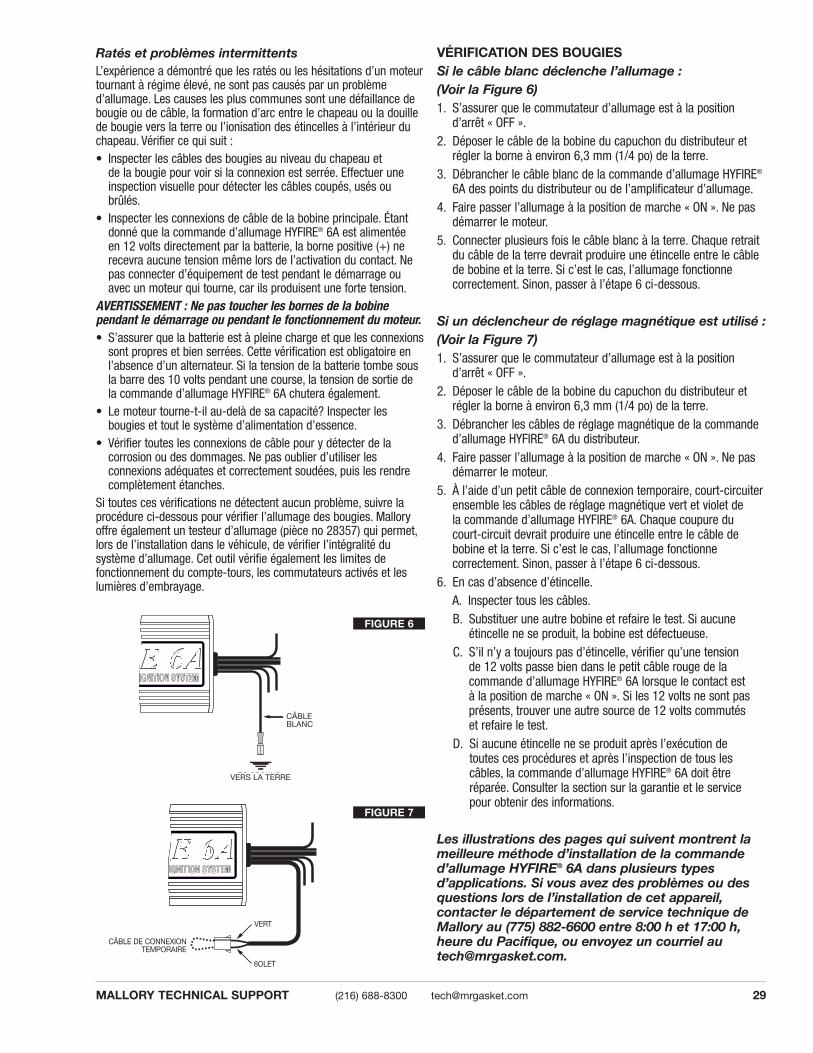
29MALLORY TECHNICAL SUPPORT (216) 688-8300 [email protected]
Ratés et problèmes intermittentsL’expérience a démontré que les ratés ou les hésitations d’un moteurtournant à régime élevé, ne sont pas causés par un problème d’allumage. Les causes les plus communes sont une défaillance debougie ou de câble, la formation d’arc entre le chapeau ou la douillede bougie vers la terre ou l’ionisation des étincelles à l’intérieur duchapeau. Vérifier ce qui suit :• Inspecter les câbles des bougies au niveau du chapeau et
de la bougie pour voir si la connexion est serrée. Effectuer uneinspection visuelle pour détecter les câbles coupés, usés oubrûlés.
• Inspecter les connexions de câble de la bobine principale. Étantdonné que la commande d’allumage HYFIRE® 6A est alimentée en 12 volts directement par la batterie, la borne positive (+) nerecevra aucune tension même lors de l’activation du contact. Nepas connecter d’équipement de test pendant le démarrage ouavec un moteur qui tourne, car ils produisent une forte tension.
AVERTISSEMENT : Ne pas toucher les bornes de la bobine pendant le démarrage ou pendant le fonctionnement du moteur.• S’assurer que la batterie est à pleine charge et que les connexions
sont propres et bien serrées. Cette vérification est obligatoire enl’absence d’un alternateur. Si la tension de la batterie tombe sousla barre des 10 volts pendant une course, la tension de sortie de la commande d’allumage HYFIRE® 6A chutera également.
• Le moteur tourne-t-il au-delà de sa capacité? Inspecter les bougies et tout le système d’alimentation d’essence.
• Vérifier toutes les connexions de câble pour y détecter de la corrosion ou des dommages. Ne pas oublier d’utiliser les connexions adéquates et correctement soudées, puis les rendrecomplètement étanches.
Si toutes ces vérifications ne détectent aucun problème, suivre laprocédure ci-dessous pour vérifier l’allumage des bougies. Malloryoffre également un testeur d’allumage (pièce no 28357) qui permet,lors de l’installation dans le véhicule, de vérifier l’intégralité du système d’allumage. Cet outil vérifie également les limites de fonctionnement du compte-tours, les commutateurs activés et leslumières d’embrayage.
JUMPER WIRE
GREEN
VIOLET
FIGURE 7
TO GROUND
WHITEWIRE
FIGURE 6
CÂBLEBLANC
VERS LA TERRE
CÂBLE DE CONNEXIONTEMPORAIRE
6OLET
VERT
VÉRIFICATION DES BOUGIESSi le câble blanc déclenche l’allumage :(Voir la Figure 6)1. S’assurer que le commutateur d’allumage est à la position
d’arrêt « OFF ».2. Déposer le câble de la bobine du capuchon du distributeur et
régler la borne à environ 6,3 mm (1/4 po) de la terre.3. Débrancher le câble blanc de la commande d’allumage HYFIRE®
6A des points du distributeur ou de l’amplificateur d’allumage.4. Faire passer l’allumage à la position de marche « ON ». Ne pas
démarrer le moteur.5. Connecter plusieurs fois le câble blanc à la terre. Chaque retrait
du câble de la terre devrait produire une étincelle entre le câblede bobine et la terre. Si c’est le cas, l’allumage fonctionne correctement. Sinon, passer à l’étape 6 ci-dessous.
Si un déclencheur de réglage magnétique est utilisé :(Voir la Figure 7)1. S’assurer que le commutateur d’allumage est à la position
d’arrêt « OFF ».2. Déposer le câble de la bobine du capuchon du distributeur et
régler la borne à environ 6,3 mm (1/4 po) de la terre.3. Débrancher les câbles de réglage magnétique de la commande
d’allumage HYFIRE® 6A du distributeur.4. Faire passer l’allumage à la position de marche « ON ». Ne pas
démarrer le moteur.5. À l’aide d’un petit câble de connexion temporaire, court-circuiter
ensemble les câbles de réglage magnétique vert et violet de la commande d’allumage HYFIRE® 6A. Chaque coupure ducourt-circuit devrait produire une étincelle entre le câble debobine et la terre. Si c’est le cas, l’allumage fonctionne correctement. Sinon, passer à l’étape 6 ci-dessous.
6. En cas d’absence d’étincelle.A. Inspecter tous les câbles.B. Substituer une autre bobine et refaire le test. Si aucune
étincelle ne se produit, la bobine est défectueuse.C. S’il n’y a toujours pas d’étincelle, vérifier qu’une tension
de 12 volts passe bien dans le petit câble rouge de la commande d’allumage HYFIRE® 6A lorsque le contact est à la position de marche « ON ». Si les 12 volts ne sont pasprésents, trouver une autre source de 12 volts commutés et refaire le test.
D. Si aucune étincelle ne se produit après l’exécution de toutes ces procédures et après l’inspection de tous lescâbles, la commande d’allumage HYFIRE® 6A doit êtreréparée. Consulter la section sur la garantie et le servicepour obtenir des informations.
Les illustrations des pages qui suivent montrent lameilleure méthode d’installation de la commanded’allumage HYFIRE® 6A dans plusieurs types d’applications. Si vous avez des problèmes ou desquestions lors de l’installation de cet appareil, contacter le département de service technique deMallory au (775) 882-6600 entre 8:00 h et 17:00 h,heure du Pacifique, ou envoyez un courriel [email protected].
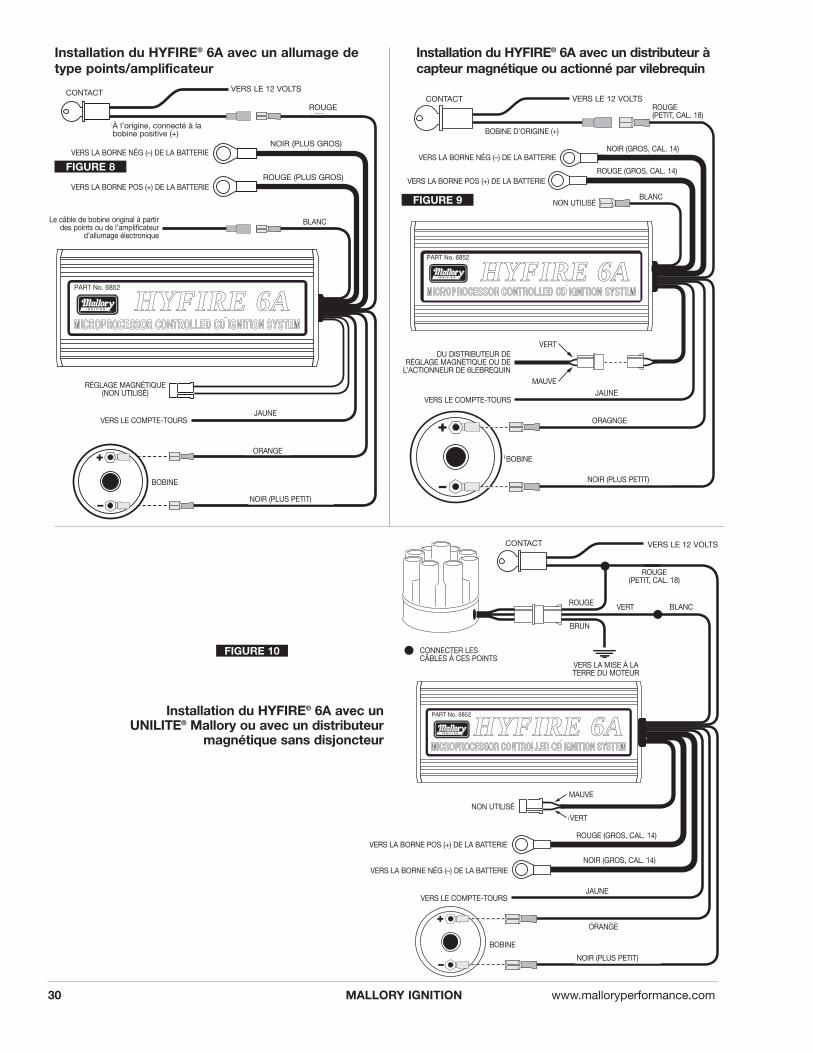
MALLORY IGNITION www.malloryperformance.com30
®
PART No. 6852
R
BLACK (SMALLER)
ORANGE
YELLOW
COIL
WHITE
GREEN
PURPLE
RED (SMALL 18 GA)
BLACK (LARGE 14 GA)
RED (LARGE 14 GA)
TO BATTERY NEG (-)
TO BATTERY POS (+)
ORIGINAL COIL (+)
IGNITION KEY
NOT USED
TO 12 VOLTS
TO TACHOMETER
FROM MAG PICK-UP DISTOR CRANK TRIGGER
®
PART No. 6852
R
IGNITION KEY TO 12 VOLTS
BLACK (SMALLER)
ORANGE
YELLOW
COIL
WHITEGREEN
BROWN
RED (SMALL 18 GA)
TO TACHOMETER
BLACK (LARGE 14 GA)TO BATTERY NEG (-)
RED (LARGE 14 GA)TO BATTERY POS (+)
RED
TO ENGINE
CONNECT WIRES AT THESE POINTS
NOT USED
GREEN
PURPLE
®
PART No. 6852
R
BLACK (SMALLER)
ORANGE
YELLOW
COIL
WHITEOriginal coil wire from points or electronic ignition amplifier
RED
BLACK (LARGER)
RED (LARGER)
TO BATTERY NEG (-)
TO BATTERY POS (+)
IGNITION KEY TO 12 VOLTS
TO TACHOMETER
MAGNETIC PICK-UP(NOT USED)
Originally connected to coil (+)
FIGURE 8
FIGURE 9
FIGURE 10
Installation du HYFIRE® 6A avec un distributeur àcapteur magnétique ou actionné par vilebrequin
Installation du HYFIRE® 6A avec un allumage detype points/amplificateur
Installation du HYFIRE® 6A avec unUNILITE® Mallory ou avec un distributeur
magnétique sans disjoncteur
CONTACTCONTACT
CONTACT
À l’origine, connecté à labobine positive (+)
VERS LE 12 VOLTSVERS LE 12 VOLTS
VERS LE 12 VOLTS
VERS LA BORNE NÉG (–) DE LA BATTERIEVERS LA BORNE NÉG (–) DE LA BATTERIE
VERS LA BORNE POS (+) DE LA BATTERIEVERS LA BORNE POS (+) DE LA BATTERIE
ROUGE
ORANGE
ORAGNGE
NOIR (PLUS GROS)
ROUGE (PLUS GROS)
Le câble de bobine original à partirdes points ou de l’amplificateur
d’allumage électronique
RÉGLAGE MAGNÉTIQUE(NON UTILISÉ)
VERS LE COMPTE-TOURS
VERS LE COMPTE-TOURS
VERS LA BORNE NÉG (–) DE LA BATTERIE
VERS LA BORNE POS (+) DE LA BATTERIE
VERS LE COMPTE-TOURS
JAUNE
JAUNE
NOIR (PLUS PETIT)
NOIR (PLUS PETIT)
ORANGE
JAUNE
NOIR (PLUS PETIT)
BOBINE
BOBINE
BOBINE
BLANC
BLANC
BOBINE D’ORIGINE (+)
ROUGE (PETIT, CAL. 18)
ROUGE (PETIT, CAL. 18)
NOIR (GROS, CAL. 14)
ROUGE (GROS, CAL. 14)
ROUGE (GROS, CAL. 14)
NOIR (GROS, CAL. 14)
NON UTILISÉ
NON UTILISÉ
DU DISTRIBUTEUR DE RÉGLAGE MAGNÉTIQUE OU DE
L’ACTIONNEUR DE 6LEBREQUINMAUVE
MAUVE
VERT
VERT
BRUN
VERS LA MISE À LATERRE DU MOTEUR
CONNECTER LESCÂBLES À CES POINTS
VERTROUGE BLANC
HHYYFFIIRREE 66AA
HHYYFFIIRREE 66AA
HHYYFFIIRREE 66AA

31MALLORY TECHNICAL SUPPORT (216) 688-8300 [email protected]
®
PART No. 6852
R
BLACK (SMALLER)
ORANGE
YELLOW
COIL
WHITENOT USED
REDORIGINAL COIL (+)
IGNITION KEY TO 12 VOLTS
TO TACHOMETER
RED (LARGE 14 GA)TO BATTERY POS (+)
BLACK (LARGE 14 GA)TO BATTERY NEG (-)
GREEN
PURPLE
®
PA
RT
No.
685
2
R
PART OF MALLORY HEI KIT P/N 29008 (NOT
INCLUDED)
YELLOW
WHITE WHITE
BLACK WHITE
WHITE (NOT USED)
SPLICE WIRES AT THESE LOCATIONS
PINK (NOT USED)
CONNECT FACTORY TACH HERE
FROM DISTRIBUTOR
TO IGNITION SWITCH
WHITE
GREEN
PURPLE
RED (SMALL 18 GA)
BLACK (LARGE 14 GA)
RED (LARGE 14 GA)
RED
RED
PINK
PINKORANGE
PINK
TO BATTERY NEG (-)
TO BATTERY POS (+)
TO TACHOMETER
FIGURE 11
FIGURE 12
Installation du HYFIRE® 6A avec un distributeur Mallory des séries 81 à 84 (2 câbles de réglage magnétique)
Installation du HYFIRE® 6A avec un système HEI de bobine à deux connecteurs
ROSE
ROSE
ROSE
PIÈCE DU KIT MALLORY,PIÈCE No 29008 (NON INCLUSE)
VERS LE CONTACT D’ALLUMAGE
À PARTIR DU DISTRIBUTEUR
CONNECTER LE COMPTE-TOURS D’ORIGINE ICI
BLANC (NON UTILISÉ) ROSE (NON UTILISÉ)
ÉPISSER LES CÂBLES À CES ENDROITS
ORANGE
VERS LE 12 VOLTS
VERS LA BORNE NÉG (–)DE LA BATTERIE
VERS LA BORNE POS (+)DE LA BATTERIE
NOIR (PLUS PETIT)
CONTACT
BOBINE D’ORIGINE (+)
ROUGE (PETIT, CAL. 18)
NOIR (GROS, CAL. 14)
ROUGE (GROS, CAL. 14)
VERS LA BORNE NÉG (–) DE LA BATTERIE
VERS LA BORNE POS (+) DE LA BATTERIE
NOIR (GROS, CAL. 14)
ROUGE (GROS, CAL. 14)
VERS LE COMPTE-TOURS
VERS LE COMPTE-TOURS
BOBINE
NON UTILISÉ
NOIR
BLANC
JAUNE
MAUVE
VERT
ORANGE
BLANC BLANC
BLANC
BLANC
JAUNE
MAUVE
VERT
ROUGE
ROUGE
ROUGE
HHYYFFIIRREE 66AA
HHYY
FFIIRR
EE 66
AA

MALLORY IGNITION www.malloryperformance.com32
4-Pin Module 5-Pin Module
®
PART No. 6852
R
WHITE
RED (SMALL 18 GA)
NOT USED
YELLOWTO TACHOMETER
BLACK (LARGE 14 GA)TO BATTERY NEG (-)
RED (LARGE 14 GA)TO BATTERY POS (+)
BLACK (SMALL 18 GA TO Cñ)
ORANGE (TO B+)
PURPLE
GREEN
WHITE
GREEN
TO ENGINE GROUND
WHITE JUMPER
KEY CONNECTOR
HEAVY RED OR PINK WIRE FROM CAR WIRING HARNESS
GREEN
PURPLE
PART OF MALLORY HEI KIT P/N 29008 (NOT INCLUDED)
PART OF MALLORY HEI KIT P/N 29008 (NOT INCLUDED)
TO TACH
BLACK (LARGE 14 GA)TO BATTERY NEG (–)
RED (LARGE 14 GA)TO BATTERY POS (+)
®
PART No. 6852
R
YELLOWTO TACHOMETER
BLACK (SMALL 18 GA TO Cñ)
ORANGE (TO B+)
TO ENGINE GROUND
NOT USED
RED (SMALL 18 GA)
WHITE
RED JUMPER
WHITE JUMPER
HEAVY PINK OR RED FROM VEHICLE WIRE HARNESS
GREEN
PURPLE
PART OF MALLORY HEI KIT P/N 29008 (NOT INCLUDED)
PART OF MALLORY HEI KIT P/N 29008 (NOT INCLUDED)
PART OF MALLORY HEI KIT P/N 29008 (NOT INCLUDED)
Installation du HYFIRE® 6A avec un moduleHEI à 4 broches (déclencheur de réglagemagnétique)
Installation du HYFIRE® 6Aavec un module HEI à 5 ou 7broches (déclencheur d’amplificateur)
7-Pin Module
FIGURE 13
FIGURE 14
FIGURE 15
Il existe trois gros chapeaux différents pour les distributeurs HEI. Pouridentifier le schéma qui convient à votre application spécifique,déposer le chapeau du distributeur et le rotor et repérer le module d’allumage situé à la base du distributeur. Compter le nombre de bornesaux deux extrémités du module et suivre le schéma correspondant. GMa utilisé des modules à 4, 5 et 7 broches dans ces distributeurs.
REMARQUE : Certains modules à 5 broches pourraient produire une hésitation ou un calage pendant une décélération. Dans ce cas,contacter le département du service technique de Mallory pour commander la diode à visser nécessaire pour corriger ce problème.
CÂBLE DE CONNEXION TEMPORAIRE BLANC
TEMPORAIRE BLANC
CÂBLE DE CONNEXIONTEMPORAIRE ROUGE
CONNECTEUR DE CONTACT
NOIR (PETIT, CAL 18 VERS C-)
ORANGE (VERS B+)
NOIR (PETIT, CAL 18 VERS C-)
ORANGE (VERS B+)
GROS CÂBLE ROSE OU ROUGEPROVENANT DU FAISCEAU DECÂBLES DU VÉHICULE
GROS CÂBLE ROSE OU ROUGE PROVENANTDU FAISCEAU DE CÂBLES DU VÉHICULE
Module à 4 broches Module à 5 broches
Module à 7 broches
PIÈCE DU KIT MALLORY,PIÈCE No 29008 (NON INCLUSE)
PIÈCE DU KIT MALLORY,PIÈCE No 29008 (NON INCLUSE)
PIÈCE DU KIT MALLORY,PIÈCE No 29008 (NON INCLUSE)
PIÈCE DU KIT MALLORY,PIÈCE No 29008 (NON INCLUSE)
PIÈCE DU KIT MALLORY,PIÈCE No 29008 (NON INCLUSE)
VERS LA BORNE POS (+)DE LA BATTERIE
VERS LA BORNE NÉG (–) DE LA BATTERIE
VERS LA BORNE POS (+)DE LA BATTERIE
VERS LA BORNE NÉG (–) DE LA BATTERIE
VERS LE COMPTE-TOURS
NON UTILISÉ
VERS LE COMPTE-TOURS
VERS LE COMPTE-TOURS
NON UTILISÉ
ROUGE (PETIT, CAL. 18)
ROUGE (PETIT, CAL. 18)
NOIR (GROS, CAL. 14)
NOIR (GROS, CAL. 14)
ROUGE (GROS, CAL. 14)
ROUGE (GROS, CAL. 14)
BLANC
BLANCO
BLANC
JAUNE
MAUVE
MAUVE
VERT
JAUNE
MAUVE
VERT
VERT
VERT
VERS LA MISE À LATERRE DU MOTEUR
VERS LA MISE À LATERRE DU MOTEUR
CÂBLE DE CONNEXION
HHYYFFIIRREE 66AA
HHYYFFIIRREE 66AA

33MALLORY TECHNICAL SUPPORT (216) 688-8300 [email protected]
BLACK (LARGE 14 GA) TO BATTERY NEG (-)
RED (LARGE 14 GA)TO BATTERY POS (+)
®
PART No. 6852
R
MAGNETIC PICKUPNOT USED
WHITE
RED (SMALL 18 GA)
RED JUMPER
WHITE JUMPER
NOT USED (TAPE END)
ORANGEBLACK (SMALL 18 GA)
FROM DISTRIBUTORPINK
BROWN
HEAVY PINK, ORANGE, OR RED WIRE
GREEN
PURPLE
PART OF MALLORY HEI KIT P/N 29008 (NOT INCLUDED)
®
PART No. 6852
R
BLACK (SMALL 18GA)
ORANGE
YELLOW
GREEN
COIL
TO TACHOMETER
BLACK (LARGE 14GA)
RED (LARGE 14GA)
PURPLE
TO BATTERY NEG (-)
TO BATTERY POS (+)
MAGNETIC PICK-UP(NOT USED)
GREEN
RED
WHITE(SMALL 18 GA)
RED (SMALL 18 GA)
Installation du HYFIRE® 6A avec une bobine externe à 4 bornes (connecteur simple)
Installation du HYFIRE® 6A avec unDuraspark de Ford, en utilisant undéclencheur à câble blanc.
FIGURE 16
FIGURE 17
BLANC
ORANGE
MAUVE
VERT
BRUN
ROSE
ROUGE
PIÈCE DU KIT MALLORY,PIÈCE No 29008 (NON INCLUSE)
NOIR (GROS, CAL. 14)
ROUGE (GROS, CAL. 14)
NOIR (GROS, CAL. 14)
ROUGE (GROS, CAL. 14)
GROS CÂBLE ROSE, ORANGE OU ROUGE
RÉGLAGE MAGNÉTIQUENON UTILISÉ
MAUVE
VERT
VERT
RÉGLAGE MAGNÉTIQUE(NON UTILISÉ)
NON UTILISÉ (ENROBER L’EXTRÉMITÉ)
CONNEXIONTEMPORAIREROUGE
À PARTIR DU DISTRIBUTEUR
CÂBLE DE CONNEXION TEMPORAIRE BLANC
ROUGE (PETIT, CAL. 18)
ROUGE (PETIT, CAL. 18)
NOIR(PETIT,
CAL 18)
ORANGE
NOIR (PETIT, CAL 18)
VERS LE COMPTE-TOURS
BOBINE
JAUNE
BLANC (PETIT, CAL. 18)
VERS LA BORNE NÉG (–)DE LA BATTERIE
VERS LA BORNE POS (+)DE LA BATTERIE
VERS LA BORNE NÉG (–)DE LA BATTERIE
VERS LA BORNE POS (+)DE LA BATTERIE
HHYYFFIIRREE 66AA
HHYYFFIIRREE 66AA

MALLORY IGNITION www.malloryperformance.com34
®
PART No. 6852
R
BLACK (SMALL 18GA)ORANGE
YELLOWTO TACHOMETER
BLACK (LARGE 14GA)
INSULATE UNUSED ENDS OF JUMPERS
TO BATTERY NEG (-)
RED (LARGE 14GA)TO BATTERY POS (+)
WH
ITE
RE
D (S
MA
LL 1
8GA
)
GREEN
PURPLEMAGNETIC PICK-UP
(NOT USED)
RED
WHITE
PART OF MALLORY HEI KIT P/N 29008 (NOT INCLUDED)
®
PART No. 6852
R
YELLOWTO TACHOMETER
BLACK (LARGE 14 GA)TO BATTERY NEG (-)
RED (LARGE 14 GA)TO BATTERY POS (+)
GREEN
PURPLEMAGNETIC PICK-UP
(NOT USED)
WHITERED
BLACK
ORANGE
GREENRED
BLACK
YELLOW
ADAPTER/HARNESS P/N 29062(NOT INCLUDED)
YELLOW BLACK
FACTORY HARNESS PLUG (ORIGINALLY CONNECTED TO THE COIL)
RED GREEN
Installation du HYFIRE® 6Aavec un TFI de Ford
(sans faisceau)
Installation du HYFIRE® 6A avec un TFI de Ford (avec faisceau)
FIGURE 18
FIGURE 19
CAPUCHON DE FAISCEAU D’ORIGINE (À L’ORIGINEBRANCHÉ À LA BOBINE)
ADAPTATEUR/FAISCEAU, PIÈCE No29062 (NON UTILISÉ)
ISOLER LES EXTRÉMITÉS NON UTILISÉESDES CONNEXIONS TEMPORAIRES
MAUVE
VERT
NOIR (GROS, CAL. 14)
ROUGE (GROS, CAL. 14)
BLANC
BLA
NC
ROUGE
ROUGE
RO
UG
E (P
ETIT
, CAL
. 18)
NOIR (GROS, CAL. 14)
ROUGE (GROS, CAL. 14)
ORANGE
JAUNE
RÉGLAGE MAGNÉTIQUE(NON UTILISÉ)
MAUVE
VERT
VERTNOIRJAUNE
JAUNE
RÉGLAGE MAGNÉTIQUE(NON UTILISÉ)
BLANC
ROUGE
NOIR
ORANGE
VERT
ROUGE
NOIR
JAUNE
NOIR (PETIT, CAL 18)
VERS LA BORNE NÉG (–)DE LA BATTERIE
VERS LA BORNE POS (+)DE LA BATTERIE
ROUGE (PETIT, CAL. 18)
PIÈCE DU KIT MALLORY,PIÈCE No 29008 (NON INCLUSE)
VERS LE COMPTE-TOURS
VERS LA BORNE NÉG (–)DE LA BATTERIE
VERS LA BORNE POS (+)DE LA BATTERIE
VERS LE COMPTE-TOURS
HHYYFFIIRREE 66AA
HHYYFFIIRREE 66AA

35MALLORY TECHNICAL SUPPORT (216) 688-8300 [email protected]
®
PART No. 6852
R
BLACK (SMALL 18 GA)
ORANGE
BLACK/GRAY OR GRAY
YELLOWTO TACHOMETER
RED (LARGE 14 GA)TO BATTERY POS (+)
BLACK (LARGE 14 GA)TO BATTERY NEG (-)
WHITE
ORIGINAL COIL (+)
GREEN
PURPLE
GREEN/ORANGE
RED (SMALL 18 GA)GREEN/ORANGE
IGNITION TO 12 VOLTS
MAGNETIC PICKUPNOT USED
BLACK/GRAYFROM POINTS OR ELECTRONIC IGNITION
ORIGINAL COIL (-)
®
PART No. 6852
R
BLACK (SMALL 18 GA)
ORANGE
COIL
WHITENOT USED
YELLOWTO TACHOMETER
RED (LARGE 14 GA)TO BATTERY POS (+)
BLACK (LARGE 14 GA)TO BATTERY NEG (-)
RED (SMALL 18 GA)FROM ORIGINAL COIL
BLACK
ORANGE
CHRYSLER MODULE
VIOLET GREEN
GREEN
PURPLE6 FT EXTENSION CABLECUT ONE END ANDSPLICE AS SHOWN
SPLICE
Installation d’un HYFIRE® 6A avec un système d’allumage électronique deChrysler, en utilisant un déclencheur deréglage magnétique.
Installation du HYFIRE® 6A avec un modèleDodge récent (avec connecteur à 2 broches)
FIGURE 20
FIGURE 21
CÂBLE DE BOBINE D’ORIGINE (+)
CÂBLE DE BOBINED’ORIGINE (–)
DES POINTS OU DE L’AMPLIFICATEURD’ALLUMAGE ÉLECTRONIQUE
NOIR/GRIS
VERT/ORANGE
VERT/ORANGE
NOIR/GRIS OU GRIS
ÉPISSER ICIMODULE CHRYSLER,LAISSER DÉBRANCHÉ
CÂBLE D’EXTENSION DE 1,8M (6 PI), COUPER UNE
EXTRÉMITÉ ET ÉPISSERCOMME IL EST ILLUSTRÉ
DE LA BORNE (+) DEBOBINE ORIGINALE
BLANC
MAUVE
VERT
6OLET
NOIR
MAUVE
VERT
VERT
ORANGE
ROUGE (PETIT, CAL. 18)
ROUGE (PETIT, CAL. 18)
BLANC
ORANGE
JAUNE
NOIR (GROS, CAL. 14)
ROUGE (GROS, CAL. 14)
NON UTILISÉ
BOBINE
ORANGE
JAUNE
NOIR (GROS, CAL. 14)
ROUGE (GROS, CAL. 14)
RÉGLAGE MAGNÉTIQUE(NON UTILISÉ)
VERS LE 12 VOLTSCONTACT
NOIR (PETIT, CAL 18)
NOIR (PETIT, CAL 18)
VERS LA BORNE NÉG (–)DE LA BATTERIE
VERS LA BORNE POS (+)DE LA BATTERIE
VERS LE COMPTE-TOURS
VERS LA BORNE NÉG (–)DE LA BATTERIE
VERS LA BORNE POS (+)DE LA BATTERIE
VERS LE COMPTE-TOURS
HHYYFFIIRREE 66AA
HHYYFFIIRREE 66AA

MALLORY IGNITION www.malloryperformance.com36
®
PART No. 6852
R
YELLOWTO TACHOMETER
RED (LARGE 14 GA)TO BATTERY POS (+)
BLACK (LARGE 14 GA)TO BATTERY NEG (-)
GREEN
PURPLE
RED (SMALL 18 GA
MAGNETIC PICKUPNOT USED
ORIGINAL COIL (+) WIRE
SPLICE HERE
WHITE
(-) BLACK (SMALL 18 GA)
AMPLIFIER
ORIGINAL COIL (-) TERMINAL FROM
AMPLIFIER
TO IGNITION SWITCH
(+) ORANGE
SPLICE HERE
Installation du HYFIRE® 6A avec une application typique pour voiture importée.
FORM 1522TLMade in U.S.A.
Printed in U.S.A.
RÉGLAGES DU LIMITEUR DE RÉGIMERepérer l’étiquette attachée à la plaque d’extrémité du HYFIRE®
6-AL. Cette étiquette indique les réglages correspondant au nombre de cylindre et aux limites de régime. Si l’étiquette estendommagée ou illisible, les réglages sont indiqués à droite.Commutateur de réglage no 4Ce commutateur doit rester à la position basse pour obtenir unfonctionnement normal. MISE EN GARDE : L’utilisation duHYFIRE® 6-AL (6AL) de Mallory avec le commutateur no 4 en position haute pourrait endommager l’allumage.
Commutateur Commutateur Commutateurrotatif no 1 no 1
Position HAUT BAS0 4,500 8,5001 4,750 8,7502 5,000 9,0003 5,250 9,2504 5,500 9,5005 5,750 9,7506 6,000 10,0007 6,250 10,2508 6,500 10,5009 6,750 10,750A 7,000 11,000B 7,250 11,250C 7,500 11,500D 7,750 11,750E 8,000 12,000F 8,250 NO LIMIT
Nombre de Commutateur Commutateurcylindres no 2 no 3
4 BAS HAUT6 HAUT BAS8 HAUT HAUT
FIGURE 22
AMPLIFICATEUR
VERS LE CONTACTD’ALLUMAGE
BORNE DE BOBINE (–)ORIGINALE PROVENANT
DE L’AMPLIFICATEUR
BLANC
(+) ORANGE
CABLE (+) DE LA BOBINA ORIGINAL
ROUGE (PETIT,CAL. 18)
ÉPISSER ICI
ÉPISSER ICI
(–) NEGRO (DELGADO DE CALIBRE 18)
JAUNE
NOIR (GROS, CAL. 14)
ROUGE (GROS, CAL. 14)
MAUVE
VERT
FIGURE 23
VERS LA BORNE NÉG (–)DE LA BATTERIE
VERS LA BORNE POS (+)DE LA BATTERIE
RÉGLAGE MAGNÉTIQUE(NON UTILISÉ)
VERS LE COMPTE-TOURS
HHYYFFIIRREE 66AA
MALLORY IS A DIVISION OF PRESTOLITE PERFORMANCE(216) 688-8300