part iv. signals - traffic sign
TRANSCRIPT
Part IV. SIGNALS A. GENERAL
4A-1 Types This part of the BIaizual relates to a gronp of clevices called high-
way traffic signals. These clevices include: traffic control signals, beacons, lane-use control sigizals, drawbridge sig~lals, emergency traffic control sigilals and train approach signals and gates.
4A-2 Basis of Installation I n most cases the iizstallation of a highway traffic control signal
will operate either to the aclvaiztage or disaclvantage of tlze vehicles ancl persons controllecl. A careful analysis of traffic operatio~ls and other factors at a large nuilzber of siglalizeci ancl ~ulsignalized inter- sections, couplecl with the judgillent of experieilcecl engineers, have ~roviclecl a series of \varrants that clefine the miniin~un conditions under which signal installations inay be justifiecl. Consequently the selection ailcl use of this control device sho~lld be preceded by a thorough engineering study of roadway ancl traffic conditions.
Eizgineering studies sl~oulcl be macle of operating sigizals to de- termine if the type of illstallation ancl the timing program meet the current requirements of traffic.
B. TRAFFIC CONTROL SIGNALS
4B-1 General Aspects There are two types of traffic control signals, pretimed and
traffic-actuated. The feat~lres of traffic control signals in which vehicle operators
and pedestrians are interested are the location, design, indications, ancl legal significailce of the signals. These are identical for all types of traffic control signals. Uniformity i11 the design features that affect the traffic to be controlled (as set fort11 in this Manual) is especially important for safe ancl efficient traffic operations.
Special police supervision and/or enforcement slzould be provided for a new non-intersection loc a t' lon.
4B-2 Area of Control A traffic control signal shall control traffic only at the intersection
or mid-bloclc Iocatioii where the installation is placed.
4B-3 Advantages and Disadvantages of Traffic Control Signals - Traffic control signals are valuable devices for the control of ve-
hicle and pedestrian traffic. However, because they assign the right- ) of-way to the various traffic movements, traffic control signals exert a profound influence on traffic flow.
Traffic control signals, properly located and operated usually have one or more of the following advantages :
1. They can provide for tlze orderly movement of traffic. 2. Wliere proper pliysical layouts and control measures are used,
they can increase tlze traffic-handling capacity of the intersection. 3. They can reduce the frequency of certain types of accidents,
especially the right-angle type. 4. Under favorable conditions, they can be coordinated to provide
for continuous or nearly continuous movement of traffic at a definite speed along a given route.
5. They can be used to interrupt heavy traffic at intervals to per- I
init other traffic, vehicular or pedestrian, to cross. Many laymen believe that traffic signals provide tlie solution to all
traffic problems at intersections. This lzas led to their~installation a t l
a large number of locations wliere no legitimate factual warrant exists.
i Traffic signal installations, even though warranted by traffic and
I I
I
roadway conditions, can be ill-designed, ineffectively placed, improp- erly operated, or poorly maintained. The following factors can result froin improper or unwarranted signal installations :
1. Excessive delay may be caused. 2. Disobedience of the signal indications is encouraged. 3. The use of less adequate routes may be induced in an attempt to
avoid suclz signals. 4. Accident frequency (especially the rear-end type) can be
significantly increased.
4B-4 Portable Traffic Control Signals A portable traffic control signal not meeting all the requirements
of this Manual, is not recognized as a standard traffic control device.
4B-5 Meaning of Signal Indications The following meanings shall be given to highway traffic signal
indications, except tlzose on pedestrian signals : 1. Green indications sliall have the following meanings :
a. Traffic, except peclestriaas, facing a CIRCULAR GREEN niay proceed straight througlz or turn right or left unless a sign at such place prohibits eitlzer such turn. But vehicular traffic, includ-
Section 11-202, Uniform Vehicle Code, Revised 1968.
ing vehicles turning right or left, shall yield the right-of-way to other vehicles, and to pedestrians lawfully within the intersection
) or an adjacent crosswallr, at the time such signal is exhibited. b. Traffic, except pedestrians, facing a GREEN ARROW,
shown alone or in combination with another indication, may cautiously enter the intersection only to make the moveiiient indi- cated by such arrow, or such other movement as is permitted by other indications shown at the same time. Such vehicular traffic shall yield the right-of-way to pedestrians lawfully within an .' adjacent crosswdk ancl to other traffic lawfully using the inter- section.
c. Unless otherwise directed by a pedestrian signal, pedestrians facing any green indication, except when the sole green indication is a turn arrow, may proceed across the roadway within any marked or unmarked crosswdk. 2. Steady yellow indications shall liave the following meanings:
a. Traffic, except pedestrians, facing a steady CIRCULAR YELLOW or YELLOTV ARROW signal is thereby warned that the relat,ed green movement is being terminated or that a red in- dication will be exhibited iminediately thereafter when vehicular traffic shall not enter the intersectioii.
b. Pedestrians facing a steady CIRCULAR YELLOW or , YELLOW ARROW signal, unless otherwise directed by a
pedestrian signal, are thereby advised that there is insufficient time to cross the roadway before a red indication is shown and no pedestrian shall then start to cross the roadway. 3. Steady red indications shall have the following meanings:
a. Traffic, except pedestrians, facing a steady CIRCULAR RED signal alone slldl stop nt a clearly inarlted stop line, but if none, before entering the crosswalk on the near side of the inter- section, or if none, then before entering the intersection and shall remain stailding until an indication to proceed is shown except as provided in b below.
b. TVhen-a sign is in place permitting a turn, tmffic, except pe- dqktriai~s, facing <steady CIRCULAR RED signal may crintio~~sly enter the kntersection tq malte the (turn indicated by such sign after stbpping as provided iri a above. Such vehicular traffic shall yie'ld the right-of-way to peclestrialzs lawfully ~vi t l~in a11 adjacent cross- walk ancl to other traffic, lawfully using the intersection.
c. Unless otherwise directed by a pedestrian signal, pedestrians facing a steady CIRCULAR RED sig-ilal alone shall not enter the roaclway.
i 'Ibid. , Ibid.
7 b, y s t J Y ; i . .... r !, dh,i;b@17-i i , . . . . . L , c ~ . . , , . . . 4 H
.: , -4 . if .- t,.<<,. . ., + 3. ' it.!.,'. . , . . I:'?: fi 5 : s . . ! ; , , . . ! ( 1 :. , I < , . ' . j l , - : . , ' . l .$ i.. . . . f . I ,
d. Traffic, except peclestrians, facing a steacly RED ARROW indication illay not enter the intersection to make the moveineat indicated by such arrow, and unless entering the intersection to make such other moveineat as is ~erniittecl by other indications shown at the same time, shall stop at a clearly illarked stop line, but if none, before entering the crosswalk on the near side of the intersection, or if none, then before entering the intersection and shall remain stancling until ail inclication to make the movenlent indicated by such arrow is sho\vn.
e. Unless otl~ermise directecl by a pedestrian signal, pedestrians -
facing a steady RED ARROW signal indication shall not enter s
the roadway. -4. Flashing signal inclicatioizs shall have the following meanings :
1 j a. Flashing red (stop signal)--\Vhen a red lens is illuminated
i with rapicl internlitteat flashes, drivers of vehicles shall stop at a 1 clearly markecl stop line, but if none, before entering the cross- walk on the near side of the intersection, or if none, then at the ,i point nearest the intersecting roadway where the clriver has a view of a~proaching traffic on the intersecting roadway before entering the intersection, ancl the right to proceed shall be subject to the rules applicable after making a stop at a STOP sign.
b. Flasl~ing yello~v (caution signal)-JVheii a yellow lens is illuminatecl with rapicl intermittent flashes, drivers of vehicles
i t
may proceed tlzrougll the intersection or past such signal only \
with caution.
4B-6 Application of Signal Indications
Basic displays nsecl in signal operations are the steady CIRCU- LAR RED, CIRCULAR YELLOTV or CIRCULAR GREEN in- dication, nsecl on each of the approaches. The application for these signal inclications ~11,211 be as follows :
1. A steady CIRCULAR RED indication :
a. Shall be given when it is intended to prohibit traffic from entering the intersection or other controlled area.
b. Should be displayecl \vith the appropriate green arrow indi- cations when it is intendecl to permit traffic to inake a specified turn or turns, ancl to prohibit traffic froin proceeding straight ahead through the controllecl area. This display is optional where it is physically iillpossible for traffic to go straight ahead, as at the head of a "T" intersection.
c. Shall be given when i t is intendecl to prohibit all traffic, ex- cept pedestrians directed by a pedestrian signal, froin entering the intersection or other controlled area.
Section 11-204, op. cit.
2. A steady CIRCULAR YELLOW indication : a. Shall be given followiiig a CIRCULAR GREEN indication
inthesamesip~1face.;2r~ 1 ' L I P - l h l : i t i b l , ' d 1, 6 3'3 - 1 ' ' iZi -
b. I s an optional alternative to a yellow arrow indication follow- ing a green arrow indication in a separate signal face used exclu- sively to coiitrol a single directional movement. 3. A steady CIRCULAR GREEN indication shall be given only
when it is intendecl to permit traffic to proceed in any direction which is lawful and practical.
4. Steady RED ARROW, YELLOW ARROTV and GREEN ARROIV indications may be nsed in lieu of tlie corresponding cir- cular indications at the following locations :
a. On an approach intersecting a one-way street. b. TVIiere certain ~novements are prohibited. c. Where certain ~novements are physically impossible. d. On an intersection approach wl~icli has an exclusive lane for
turning move~neiits. e. Where ttlriiing movements are L'protected" from conflicting
movements by other indications or by the signal sequence. f. Jvliere all the inovements on the approach clo not begin or
encl at the same time and where the inclications for the turning movements will also be visible to traffic with other allowable movements. If steady arrow indications are used :
a. A steady RED ARROW indication sliall be used only in a separate signal face whicli also contains steady YELLOW ARROTV ancl GREEN ARROW indications. It shall be used for controlliiig only a single traffic movement.
b. A steady YELLOTV ARROW indication sliall be used fol- lo~ving a GREEN ARROW indication (~vhich has been displayed simultaneously ~vitll a CIRCULAR RED indication in the same signal face).
c. A steady YELLOW ARROTV indication inay be used (in a separate signal face) following a GREEN ARROW indication, when tliat face is nsed exclnsively to control a single directional moveinelit.
d. A steady YELL0147 ARROW indication may be used to in- dicate the clearance interval following the termination of a GREEN ARROW iilldication (wl~ea displayed siinultaneously with a continuing CIRCULAR GREEN ilzclication in the same signal face).
e. A steady GREEN ARROTV indication shall be used only ~vl~eii there ~ ~ o n l d be no conflict with other vehicles or ~vitli pe-
a ion. destpians crossing in conformance ~vitli the TVALIS: indic t'
5. The following coinbinations of signal indications shall not be sim~xltaneo~~sly displayed on any one s ig i~d face, and shall not be simultaneously displayed in different signal faces on any one ap- ~"oach to a11 intersection unless the signal faces are shielded, hooded, ) louvered, positioned or designecl so that nolie of these prohibited combinstioils of signal indications is readily visible to drivers :
a. CIRCULAR GREEN wit11 CIRCULAR YELLOW. b. Straight-through GREEN ARROTV with CIRCULAR
RED. c. CIRCULAR RED with CIRCULAR YELLOW. d. CIRCULAR GREEN with CIRCULAR RED. e. CIRCULAR GREEN ~vitll RED ARROW.
6. TVllen a traffic control signal is put oil flashing operation, normally a yellow indication should be used for the major street and a recl indication for the other approaches. Yellow indications shall not be used for all approaches. The following applications shall apply ~vhenever signals are placed in flashing operation :
a. A CIRCULAR YELLOW indication shall be flashed instead f of any YELLOW ARROW indication \vhicll inay be included in that signal face.
i b. No CIRCULAR GREEN or GREEN ARROW indication 1
or flashing yellow indication shall be terininated and immediately followed by a steady red or flashing red indication without the d i s~ lay of the steady yellow change indication; however, transi- tion may be inade directly froin a CIRCULAR GREEN or GREEN ARROW indication to a flashing yellow indication.
4B-7 Number of Lenses per Signal Face 0 3 ' -
Each signal face, except in pedestrian signals~sl~all have at least three lenses, but not inore than five. The lenses shall be red, yellow or green in color, and shall give a circular or arrow type of indica- tion. Allowable exceptions to the above are :
1. Where a single section green arrow lens is used alone to indicate a continuous movement.
2. As cliscussed under Unexpected Conflicts During Green Interval (sec. 4B-16).
3. Where one or more indications are repeated for reasons of safety or impact.
4.B-8 Size and Design of Signal Lenses
The aspect of all signal lenses, except in pedestrian signals, shall be circular. There shall be two sizes for lenses, 8 inches and 12 inches nominal cliameter. u -
Twelve-inch lenses normally should be used : 1. For intersections with 85 percentile approach speeds exceeding
40 mph. 2. For intersections where signalization might be unexpected. 3. For special problem locations, such as those with conflictiilg or
competing backgro~uld lighting. 4. For intersections where drivers may view both traffic coiztrol
and lane-direction-control signs simultaneously. 5. For all arrow indications. Arrows shall be pointed vertically upward to indicate a straight-
tlirougl~ movement and in a horizontal direction to indicate a turn at approximately right angles. TVhen the angle of the turn is sub- stantially different from a right angle, the arrow should be posi- tioned oil an upward slope at an angle approximately equal to that of the turn.
Each arrow lens shall show only one arrow direction. The arrow shall be the only illuminated part of the lens visible.
I11 no case shall letters or nuinbers be displayecl as part of a ve- hicular signal indication.
Except for the requirements of this section, all lenses shall con- form to the Standard for Adjustable Face Vehicle Traffic Control
, Signal Heads, 1970 E d i t i ~ n . ~
4B-9 Arrangement of Lenses in Signal Faces
The lenses in a signal face shall be arranged in a vertical or horizontal straight line, except that in a vertical array, lenses of the same color may be arranged horizontally adjacent to each other at right angles to the basic stmigl~t line arrangement (fig. 4-1). Sncli clnsters shall be limited to two identical lenses or to two or three different lenses of the same color.
I n each signal face, all red lenses in vertical signals shall be located above, and in liorizontal signals shall be located to the left of all yellow and green leases.
A CIRCULAR YELLOW lens shall be located between the red lens or/lei'is@s and nll other lenses.,
I n ~ertically arranged signal faces, each YELLOW ARROW lens shall be located immediately above the GREEN ARROW lens to which it applies. I n horizoiltally arranged signals, the YELLOW ARROW shall be located immediately to the left of the GREEN ARROW lens.
; 'Available from the Institute of Traffic Engineers, Washington, D.C. 20006

Figure 4-1. Typical orrangemenfs of lenses in signal faces.
Tlze relative positions of lenses within the signal face shall be as follows :
1. I11 a vertical signal face froill top to bottom : CIRCULAR RED Left t~u.11 RED ARROTV Right turn RED ARROTV CIRCULAR YELLOW

Straight through YELLOW ARROW Straight tllrough GREEN ARROTV CIRCULAR GREEN Left turn YELLOW ARROTV Left turn GREEN ARROTV Right turn YELLOW ARROW Right turn GREEN ARROTV
2. I n a horizontal signal face from left to right: CIRCULAR RED Left turn RED ARROW Right turn RED ARROW CIRCULAR YELLOW Left tun1 YELLOW ARROW Left turn GREEN ARROW CIRCULAR GREEN Straight through YELLOW ARROW Straight through GREEN ARROW Right turn YELLOW ARROTT Right turn GREEN ARROW
3. I11 a cluster, iclentical signal indications inay be repeated in adjacent vertical or horizoatal locations ~v i t l~ ia the saizie signal face. If adjacent iilclications in a cluster are not identical, their arrange- inent shall follow paragraph I or 2 above, as applicable.
Basic horizontal and vertical display faces nlay be usecl on the saine approach in-ovidecl they are separated to meet the lateral clearance required in section 4B-12.
Fig~we 4-1 sho~vs sonie possible arrangeinents of lenses in signal faces.
4B-10 Illumination of Lenses
Each signal lens shall be illnniinated independently. When a signal lens, except in a pedestrian signal, is ill~uninated
and the view of such an iizclication is 11ot otherwise physically ob- structed, it shall be clearly visible (to drivers it controls) for a distance of a least 1/4 mile under nornlal atmospheric conditions.
The intensity and clistribution of light froin each illulliiilated signal lens shot~ld conforin to the Standarcl for Adjustable Face Vehicle Traffic Control Signal Heads, Revisecl 1970; and the Stand- arc1 for Traffic Signal Lainps, Deceinloer 1967.
When 12" lens signals wit11 150 matt Ianlps are placed on flashing for nigl1ttilne operation a id the flashing yello~v indication is so bright as to cause excessive glare, an autoinatic dinlining device should be usecl to recluce the brilliance of the flashing 12" yellow.
4B-11 Visibility and Shielding of Signal Faces
Each signal face shall be so adjusted that its indications will be of maximum effectiveness to the approaching traffic for which they are intended.
Visors should be used on all signal faces to aid in directing the -
signal indication specifically to approaching traffic, as well as to reduce "sun plzantom" resnltiizg from external light entering the lens. Back-plates nornially should be used on one-way and back-to-
+
back two-way overlzeacl signals, and when one signal face controls -
a movement.
I n general, vehicular signal faces should be aimed to have maxi- mum effectiveness for an approaching driver located a distance from the stop line e q ~ ~ a l to tlie distance traversed while stopping. This distance sliould include tliat covered while reacting to the signal as well as that covered while bringing tlie vehicle to a stop from an average approach speed. The influence of curves, grades, and ob- structions sliould be considered in directing and locating signals.
i Irreg~llar street design frequently necessitates placing signals for 1
different street approaches wit11 a. comparatively small angle be- tween their indications. I n these cases, each signal indication shall, I to the extent practicable, be shielded or directed by visors, louvers, or other means so that an approaching driver can see only the indica- tion controlling his movement. Tunnel visors exceeding 12" in length shall not be nsed on free-swinging signals.
The foregoing does not preclude the use of special signal faces such tliat the clriver does not see their indications before seeing other indications further ahead, when simultaneous viewing of both sifgnal indications could cause tlie driver to be misdirected.
4B-12 Number and Location of Signal Faces Tlie primary coiisideratioii in signal face placement shall be
visibility. Drivers approacl~ing a signalized intersection or other signalized area, such as a mid-block crosswalk, shall be given a clear and uniiiistakable indication of tlzeir right-of-way assignment. Critical elements are lateral ancl vertical angles of sight toward a signal face, as determined by typical clriver eye position, vehicle design, and tlie vertical, longituclinal and lateral position of the signal face. The geometry of each intersection to be signalized, in- cluding vertical grades aiicl horizontal curves, should be considered in signal face placement.
The visibility, location and number of signal faces for each ap- roach to an intersection or a mid-block crosswalk shall be as follows :
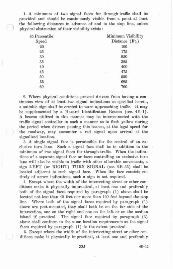
1. A minimum of two signal faces for through-traffic shall be provided and should be continuously visible from a point at least the following distances in advance of and to the stop line, unless physical obstntction of their visibility exists :
85 Percentile Speed
20 25 30 35 40 45 50 55 60
Minimum Visibility Distance (Ft.)
100 175 250 325 400 475 550 625 700
2. Where physical conditions prevent drivers from having a con- tinuous view of at least two signal indications as specified herein, a suitable sign shall be erected to warn approaching traffic. It may be supplemented by a Hazard Identification Beacon (sec. 4E-1). A beacon utilized in this manner may be interconnected with the traffic signal controller in such a manner as to flash yellow during the period when drivers passing this beacon, at the legal speed for the roadway, may encounter a red signal upon arrival at the signalized location.
3. A single signal face is permissible for the control of an ex- clusive turn lane. Such a signal face sllall be in addition to the minimuin of two signal faces for through-traffic. When the indica- tions of a separate signal face or faces controlling an exclusive turn lane will also be visible to traffic with other allowable movements, a sign LEFT (or RIGHT) TURN SIGNAL (sec. 2B-35) shall be located adjacent to such signal face. When the face consists en- tirely of arrow indications, such a sign is not required.
4. Except where the width of the intersecting street or other con- ditions inalie i t physically impractical, at least one and preferably both of the signal faces required by psragral~h (1) above shall be located not less than 40 feet nor more than 120 feet beyond the stop line. Where both of the signal faces required by paragraph (1) above are post-mounted, they shall both be on the far side of the intersection, one on the right and one on the left or on the median islancl if practical. The signal face required by paragraph (3) above sllnll conforin to the sxine location req~~irements as the signal faces required by paragraph (1) to the extent practical.
5. Except where the ~vidtll of the intersecting street or other con- ditions inalie it pllysically impractical, at lexst one and preferably

both of the signal faces repirecl by paragraph (1) above sllall be locatecl bet~veen two lines intersecting wit11 the center of the ap- proach lanes a t the stop line, one making an angle of approximately 20 clegrees to the right of the center of the approach extended, and the other making an angle of approximately 20 degrees to the left of tlie center of the approach extei~clecl (fig. 4-2).
\---- ----- --- A\ \---------- LC*; - 0 C 2. 3 0. -
\ Approx.20° / 3 m ' E -
Figure 4-2. Desirable locafion of signal faces.
6. Near-side sigaals should be locatecl as near as practicable to the stop line.
7. TV11ere a sigiial face controls a specific lane or lanes of ap- proach, its transverse position shoulcl be uni~iistakably in line with the pat11 of that inoveinent.
8. Required signal faces for any one approach shall be not less thaii eight feet apart measnrecl horizontally between centers of faces.
9. When tlie ilearest signal face is inore than 120 feet beyoncl the stop line, a suppleiiiental near sicle siganl indication shall be - provided. -
10. A signal face mounted oil a span wire or innst arin shonld be I
locatecl as near as practicable to the line of the driver's noriilal view. 11. Su~plemental signal faces shoulcl be usecl 11711e11 a11 engineering
stucly has slio~vn that tliey are iieeclecl to achieve both acl~raiice and inliliecliate intersection visibility. When usecl, tliey should be lo-

catecl to provicle optin~uin visibility for tlze inoveinent to be con- trollecl. The following limitations apply :
' 1 a. Left t~urn arrows shall not be used in near-riglzt faces. b. Right turn arrows slzall not be used in far-left faces. A far-
sicle ineclisuz ino~ult signal shall be consiclered as a far-left signal for this application. A t signalizecl micl-block crossmdks, there should be a t least one
signal face over the traveled roaclway for each approach. I11 other respects, a traffic control signal a t a izzicl-bloclc location slzall meet tlze requirements set fort11 herein.
The transverse location of a signal face, slzall, if inoulzted on tlze top of a post or on a short bracket froin it, coizforln with section 4B-14.
S u ~ ~ l e r n e n t a r y pedestriail signals shall be usecl wvllere ~varraizted as proviclecl in section 4D-3.
4B-13 Height of Signal Faces
The bottoin of tlze housing of a sigizal face, not niounted over a road~vay, slzall not be less tllail 8 feet nor inore than 15 feet above the sicle~valk or, if none, above the paveinent grade a t tlze center of the higllway.
The botton~ of the housing of a sigllal face suspeizclecl over a. road- way slzall not be less than 15 feet nor inore tllan 19 feet above the paveinent gracle a t the center of the roaclmay.
JVitlzin the above limits, optiin~ul? visibility ancl aclequate clear- ance sl~oulcl be the gnicling co~zsicleratioi~s in clecicling signal height. Grades on approacl~ing streets inay be important factors, aizcl slzoulcl be consiclerecl in cleteriniizing the inost appropriate height.
4B-14 Transverse Location of Traffic Signal Supports and Controller Cabinets
111 the placenlei~t of signal s~~ppor t s , priinary consicleration sllall be given to ensuring the proper risibility of signal faces as clescribed in sections 4B-12 ancl 13. However, in the interest of safety, signal supports and controller cabinets sl~oulcl be placecl as far as prac- ticable froin the eclge of the travelecl way ~vitllont aclversely affecting signal visibility.
Supl~orts for post-nlountecl sigizal lzeacls a t the sicle of a street wit11 curbs sllall hare a horizontal clearance of not less tllan two feet froill the face of a vertical curb. Where there is no curb, s~upports for ~ost-motultecl signal heacls shall have n liorizontal clearance of not less t l ~ a n t ~ v o feet froill the eclge of a slloulcler, ~ ~ i t h i n tlze liinits of izom~al vertical clearance. A signal support shouIc1 not obstruct a
' crosswalk.

No part of a concrete base for a signal support should extend more than 4 inches above the grouncl level at any point, except that this limitation does not apply to the concrete base for a rigid (non- 1 breakaway) support.
On medians, the above inininiuin clearances for signal supports shoulcl be obtainecl where practicable. Any supports which cannot be located with the reqnired clearances should be of the breakaway type or should be guarded if at all practicable.
4B-15 Vehicle Change Interval
A yellow vehicle cllange interval shall be usecl following each CIRCULAR GREEN intervaJ ahd, \vher,e :appligable /af&r~&aeh GREEN $ARROW J.inter,val. I n !no- ~casez-shallz a~~BIE@V,EA-R
, , I II YEZhOTV-indication-be displayed in, conjunction %it11 the cl~ange h L 8 L frtun,CIRCULAR REkD to CIRCULAR GREEN. Separate signhl
$aces should be used ,~vl~eil exclnsive t~~ri~ing~morveinents are-qoa- trolled by,GR-EBN ARROWS (sec. 4B-6).
The exclusive function of the steady yellow interval sl~all be to warn traffic of an impencling change in the right-of-way assignment.
Yellow vehicle change intervals should have a range of approxi- inately 3 to 6 seconds. Generally the longer intervals are appro- priate to higher approach speeds.
The yellow vehicle cl~ange interval may be followed by a short all- way red clearance interval, of sufficient duration to permit the inter- section to clear before cross traffic is released.
A clearance interval shall be provided between the termination of a GREEN ARROW inclication ancl the sllowing of a green indica- tion to any conflicting traffic niovement.
4B-16 Unexpected Conflicts During Green Interval
No movement that inay involve an ~ulexpectecl crossing of path- ways of moving traffic should be inclicated cluring any green interval, except when :
1. The movement involves only slight hazard ; 2. Serious traffic clelays are materially reduced by permitting the
conflicting inoveinent ; ancl 3. Drivers and pedestrians s~~bjected to the unexpectecl conflict are
effectively warned thereof.
When such conditions of possible unexpected conflict exist, warning may be given by s sign or, by the use of an appropriate signal indi- cation as set forth in section 4R-'7. The foregoing applies to vehicle- pedestrian conflicts as well as to vehicle-vellicle conflicts.
I
4B-14 228 1
4B-17 Coordination of Traffic Control Signals
Traffic control signals within one-half of a mile of one another along a major route or in a networlr of intersecting inajor routes should be operated in coordination, preferably with interconnected controllers. However, coordination need not be maintained across bounclaries between signal systems ~vhicll operate on different time cycles. Coordinated operation normdly should include both pre- timed signals and traffic-actuated signals within the appropriate distances.
For coordination with railroad grade crossings signals see section 4B-21.
4B-18 FIashing Operation of Traffic Control Signals All traffic signal instdlations shall be provided with an electrical
flashing mechanism supplementary to the signal timer. A manual switch, or where appropriate, automatic means, sliall be provided to ac t~~a te the flashing inecliai~isin. The signal timer shall be removable without affecting tlie flashing operation. The mechanism shall op- erate in a manner siinilar to that of an Intersection Control Beacon (sec. 4E-3) to provide intermittent illumination of selected signal lenses.
The ill~uninating element in a flashing signal shall be flashed con- tinuously at a rate of not less than 50 nor more than 60 times per minute. The ill~uninated periocl of each flash shall be not less than half and not more than two-thirds of the total flash cycle.
When traffic control signals are put on flashing operation, the signal indications given to the several streets shall be as specified in section 4B-6.
Automatic changes from flashing to stop-and-go operation shall be made at the beginning of the major street green interval, pre- ferably at the beginning of the common inajor street green interval, (i.e., when a green indication is sliowiz in both directions on the major street). Automatic changes froill stop-and-go to flashing operation shall be made at the end of the coillnion inajor street red interval, (i.e., when a red indication is sho~vn in both directions on the major street).
The change from the flashing to stop-and-go operation, or from stop-and-go to flashing operation by manual switch may be made at any time.
Where there is no comiiion liiajor street green interval, the auto- matic change from flashing to stop-ancl-go operation shall be made at the beginning of the green interval for the major traffic move- ment on tlie major street. It may be necessary to provide a short, steady all-red interval for the other approaches before changing from flashing yellow or flashing recl to green on the inajor approach.
4B-19 Continuity of Operation A traffic signal installation, except as provided below, slla11 be
operated as a stop-and-go clevice or as a flashing clevice. When s signal installation is not in operation such as prior to
1 placing i t in service, during seasonal sl~utclon~ns, or wl~en it is not desirable to operate the signals, they should be Izooded, turnecl or
a 1011. talcen down to clearly inclicate that the signal is not in oper t ' When a traffic signal installation is being operated ill the usual
(stop-ancl-go) manner, a t least one indication in each signal face shall be illuminated.
Wlzen a traffic signal installation is being operated as a flashing de- vice, the yellow inclication shall be flashecl in a t least two required signal faces (sec. 4B-12) on each approacll 011 which traffic is not stopped and the red indication slza11 be flashecl in a t least two re- quirecl signal faces (sec. 4B-12) on each approach on wllicli traffic '
is required to stop. The above provisions do not apply to emergency-traffic sigiials or
draw-bridge signals. TVhen a single-section, contin~~ously illun~inatecl GREEN
ARROTTT lens is usecl alone to indicate a continuous nioveinent, i t may be continuonsly illuniinatecl nd~en the other signal indications in the signal installation are flashed.
4B-20 Signal Operation Must Relate to Traffic Flow Traffic control signals shall be operated in a ~nanner consistent
with traffic requireinents. Data froin engineering studies shall be usecl to cieterniine the proper phasing and tinling for a signal.
Since traffic flows ancl patterns change, it is necessary that the engineering clata be upclated ancl re-eralnatecl regularly.
To assure that the approrecl operating pattern i~lclucling tillling is clisplayecl to the driver, regular checlrs including the use of accurate timing devices should be made.
4B-21 Traffic Signals Near Grade Crossings When a railroacl grade crossing, protectecl by train-approacll
signals (secs. 4P-1 and 2), is within or near an intersection con- trollecl by a traffic control signal, the control of the traffic signal should be preeml>tecl from the signal controller npon approacll of - trains to avoicl coaflicting aspects of the traffic signal ancl the train- , - apl~roacll signal. This preeinption feature requires a closecl elec- trical circuit between the control relay of the train-approach signals j ancl the preemptor in order to establish ancl niaintain the preempted coizclition cluring the time that the train-approach1 signals are in I
operation. Except uncles unusual circ~ulzstances, the iizterconnection shoulcl be liinitecl to the traffic signals within 200 feet of the crossing. 1
! I
4B-19 230 i
i
Traffic control signals shall not be usecl on nlainlilze railroacl cross- ings in lieu of railroacl ~ rac l e crossing protection devices. However,
P a t iacl~~strial track crossings and other places where train nzovelnents are w r y s l o ~ ~ (as in s\r~itclzing operations), traffic control signals may be usecl in lieu of conventional train-approach signals to warn motorists of the approach or presence of a train. The provisions of
a ion tlzis part relating to traffic signal design, iilstallation and oper t' are applicable as appropriate where traffic coiitrol signals are so used.
A t crossings ~vhere ti.ain nzorements are regulatecl or liniited to the extent that train-apl~roach sig~zals are not required, preemption of the adjacent sigtializecl intersections inay be desirable to pei-nzit non- conflicting I~ ig l~way traffic to proceed during tlze tiizle tlze crossing is blocked by a train. Except luzcler unusual circ~~mstances, tlze inter- connectioiz slzoulcl be limited to the traffic signals within 200 feet of the crossing.
The preenlptioiz sequence initiated when the train first enters the approach circuit, shall a t once bring into effect a signal display whiclz mill perinit all vehicles to clear the tracks before the train reaches the iiztersection or any approach thereto.
TVlleiz the green iizclicatiolz is preeinptecl by train operation, a yellow clzaizge interval 11111st be inserted in the signal sequence in the interest of safety and coizsistency. To avoicl iliisiilterpretatioiz dur-
1 ing the tiizle that the clear-out signals are green, consideration should be given to the use of 12-inclz red lenses in the signals which goreriz moven~ent over the tracks (sec. 4B-8).
After the track clearance ,phase, the traffic control signal i n q be operated to permit ~el l icle inoremeats that do not cross the tracks, but in all cases shall prohibit izzovelneizts over the tracks.
7Vlzere feasible the location and the normal (no trains involved) pl~asing and timing of traffic control signals near railroacl grade crossings slzonlcl be designecl so that T-elzicles are not required to stop on the tracks even though in soine cases this will increase the waiting tinze. The exact nature of the display and the Iocatioa of the signals to accomplislz tlzis will clepeizd on tlze physical relationship of the tracks to the intersection area.
TVllen the train clears the crossiilg i t is necessary to return the signal to a clesigilated phase, izor~llally the traffic movelnent crossing the traclcs.
As usecl herein, the terlns "train" and "railroad" shall include transit vehicles operating upon stationary rails or tracks on private right-of-way.
4B-22 Emergency Operation of Traffic Signals
Systems in ~ ~ h i c l z traffic coiltrol signals are preeinptecl by emer- gency relzicles shall operate to pennit a nornzd change interval to
take place in the change froin green to yellow to red (or flashing red) before arrival of the emergency vehicle at the preempted lo- cation. Systems in wliiclz traffic control signals are preempted by emergency vehicles shall be designed and installed so as to provide an indication to the driver of any emergency vehicle approaching an intersection when the equipment fails to preempt tlze traffic signal at that intersection. This indication shall be designed to be given whether the failure results from a prior preenzption by an emergency vehicle on the cross street, by a railroad preemption, from equipment malfunction, or from any other cause.
Traffic signals operating in congested areas during emergency conditions shonld be operated in a manner designed to keep traffic moving. Prolonged all-red or flashing signal sequences are to be avoided.
4B-23 Maintenance of Traffic Control Signals
Prior to the installation of any traffic control signal, the re- sponsibility for its maintenance should be clearly established. The responsible agency should provide for the maintenance of tlie signal and all of its appurtenances in a responsible manner. To this end the agency should:
1. Provide for alternate operation of the signal during a period of failure, either on flash or manually, or by having manual traffic direction by proper authority as may be warranted by traffic volumes or congestion, or by erecting other traffic control devices.
2. Have properly skilled maintenance available without undue de- lay for all emergency calls, including lamp failures.
3. Provide properly sltilled maintenance for all components. 4. Maintain tlze appearance of the installation in a manner con-
sistent with the intention of this Manual, with particular emphasis on painting and on cleaning of the optical system.
5. Service equipinent and lamps as frequently as experience proves necessary to prevent undue failures.
6. Provide adequate stand-by equipment to izziniinize the interrup- tion of signal operation due to equipment failure.
Every controller should be kept in effective operatioiz in strict accordance witlz its predetermined timing scliednle.
A careful check of tlze correctness of time operation of the con- troller should be made frequently enough to insure its operating in accordance with tlie planned timing sclzedule. Timing changes should be made only by authorized persons. A written record should be made of all timing changes.
Controllers should be carefully cleaned and serviced at least as frequently as specified by the manufacturer and more frequently if experience proves it necessary.

4B-24 Painting
The insides of visors (hoods) and the entire surface of louvers, 1 and fins, and the front surface of backplates shall have a dull black finis11 to minimize light reflection to the side of tlle signals.
To obtain tlle best possible contrast with the visual background, it is desirable to paint signal head housings highway yellow.
4B-25 Vehicle Detectors
The placement of vehicle detectors in relation to the Stop line is a very important factor in the proper operation of traffic actuated signals and should be a factor in signal design.
Where the total entering traffic on one street is more than twice that on the cross street, detectors on the cross street shot~ld be placed closer to the stop line than on tlle main street.
Additional "calling" detectors may be required on lower volume streets to handle traffic entering the street from driveways between the basic detector and the Stop line.
The transverse placement of detectors should be such that vehicles traveling amay froill the intersection do not register L'false-calls." On narrow two-way roaclways this may require use of directional detectors.
4B-26 Auxiliary Signs
Signal instruction signs (sec. 2B-35) used with traffic signals shall be located adjacent to the signal face to which they apply. Mini- mum clearance of the tots1 assembly shdl conform to the provisions of sections 2A-23 and 4B-13.
Stop signs shall not be used in coiljunction with any signal opera- tion, except :
1. When the indication flashes red at all times or 2. When a iiiinor street or driveway is located within or adjacent
to the controlled area, but does not warrant separate signal control due to extremely low potential for conflict.
TVhen used in conjunction with traffic signals, illu~iiiinated signs shall be designed and inountecl in such a manner as to avoid glare and reflections that seriously cletract from the signal inclications. The traffic control signal shall be given cloniii~ant position and brightness to assure its target priority in tlle overall display.
Traffic Signal Speecl signs (sec. 2D49) may be used to inform drivers of the speecl of progression, if this speed is substantially lower than tlle speed limits in effect on streets in the signal system.
4B-27 Removal of Confusing Advertising Lights
There sllonlcl be legal authority to prohibit tlze display of ally un- authorizecl sign, signal, illarlcing, or clevice ~vhicll interferes with the effectiveiless of ally official traffic coiltrol clevice. Specific refer- ence is nlacle to Sectioil 11-205, Uiliforilz Vehicle Cocle-Revisecl 1968.
C. WARRANTS
4C-1 Advance Engineering Data Required
A compreliensive iar7estigatioa of traffic coilclitioils aiicl physical characteristics of tlle locatioil is r eq~~ i red to cleteriniile the necessity for a signal i~lstallatio~l and to fnrnisll necessary data for the proper design ailcl operation of a signal that is fo~uld to be warranted. Sucll data desirably sl~ould iilclude :
1. The aunlber of vehicles entering the iatersection in each hour from each approach cluriilg 16 coilsecutive hours of a represei~tative day. The 16 llours selected should contain the greatest percentage of the 24-hour traffic.
2. Vehicular voluliles for each traffic moveilient from each ap- roach, classifiecl by vehicle type ( l i ea~~y trncks, passenger cars and light trucks, and public-trailsit vehicles), cluring each 15-minute period of tlle tnlo hours i11 the morning and, of the two llours in the afterilooil during ~ v l ~ i c h total traffic elitering the iiltersectioil is greatest.
3. Pedestriail volume counts oil each crosswalk during the same periods as tlle vehicular counts i11 paragraph (2) above ailcl also cluriizg llours of higllest peclestriaa ~oluine, TTTl~ere youilg or elderly persons need special consideratioa, the peclestriails illay be classified by general observatioil ailcl recorclecl by age gronps as follows:
a. under 13 years b. 13 to 60 years c. over 60 years.
4. The 85-percelltile speed of all vel~icles on the ~ulcontrollecl ap- proaches to the locatioil.
5. A coilclitioils cliagram showing cl&ails of the pllysical layout, including such features as il~tersectioilal geoiizetrics, cllannelization, grades, sight-distance restrictions, bus stops ancl routings, parlcing coilclitions, pavemeiit marlciags, street lighting, clrive~vays, locatioil of nearby railroacl crossings, distance to nearest sigaals, utility poles and fixtures, and acljacent land use.
6. A collisioil diagram sllowing accideilt experience by type, loca- tion, directioil of movemeilt, severity, time of day, clate, ancl clay of wee$ for a t least one year.
The follo~viiig data are also desirable for a more precise under- standing of tlie operation of tlie intersection ancl may be obtained during tlie periods specifiecl in (2) above :
f e. Vehicle-seconds delay determined separately for e d i approach. The ii~uiiiber a11cl distribution of gaps in veliicular traffic on tlie
L: major street ~vlieii minor-street traffic fiiicls it possible to use tlie in- tersection safely.
3. The 85-percentile speed of veliicles on coiitrollecl approaches at a point near to tlie intersection but unaffected by the control.
4. Peclestriaii clelay time for at least two 30-inin~~te peak pedes- trian clelay periocls of an average weekday or like periods of a Saturday or a Sunday.
Aclequate roadway capacity at a sig~ialized intersection is desir- able. TVicleiiing of both tlie iiiain liigliway aiicl tlie intersecting roacl- way may be warranted to recluce tlie delays causecl by assigiiinent of riglit-of-may at iiitersectioiis controlled by traffic signals. Widening of tlie intersecting roacl~vay is often beneficial to operation on tlie niain liigliway because it recluces tlie sigilal tiine that must be as- signed to side-street traffic. I n urban areas, tlie effect of widening can be acliievecl by elimination of parking at intersectional ap- proaclies. It is always desirable to have at least two lanes for moving traffic on eacli approacli to a signalizecl iiitersectioii. Aclditional wicltli iiiay be necessary on tlie leaving side of the intersection, as
\ well as tlie approach side, in order to clear traffic tlirougli tlie inter- section effectively. Before an intersection is widelied, tlie aclditional green time iieedecl by pedestrians to cross tlie widenecl streets should be clieclcecl to enstwe tliat it will not exceecl tlie green time saved tlirougli iiiiprovecl veliicular flow.
4C-2 Warrants for Traffic Signal Installation
Traffic control signals should not be iiistallecl unless one or niore of the signal ~varraiits in tliis M a n ~ ~ a l are iiiet. Informatioii sliould
I be obtaiiiecl by means of engineering studies and compared mitli tlie 1 req~~ireineiits set fort11 in tlie warrants. I f these requirements are I not met, a traffic signal sliould neitlier be put into operation nor
i continued in operation (if already installed). TVIieii a traffic control sigiial is iiiclicatecl as being ~varranted, it is
presumed tliat tlie signal and all related traffic coiitrol devices and inarkiiigs are iiistallecl accorcliag to tlie standards set fortli in tliis Manual. It is further presumecl tliat signal iiiclications are properly phasecl, tliat roadways are properly designed, that adjacent traffic signals are properly coorcliiiatecl, that there is adequate supervision of the operation and iiiaiiitenance of tlie signal ancl all of its related devices, ancl that tlie traffic sigiial controller mill be selected on tlie
x 1 basis of engineering study and j~~clgment.
An investigation of the need for traffic signal control sho~~ ld in- - elude where applicable, at least an analysis of the factors contained in the following warrants :
Warrant 1-ISliniin~~in vehicular volume. Warrant 2-Interr~~ption of contin~~ous traffic. Warrant 3-IS/Iinirn~1m pedestrian voltxme. Warrant 4-School crossings. Warrant ti-Progressive movement. f Warrant 6-Accident experience. - Warrant 7-Systems. - Warrant 8-Co~nbination of warrants.
4C-3 Warrant 1, Minimum Vehicular Volume
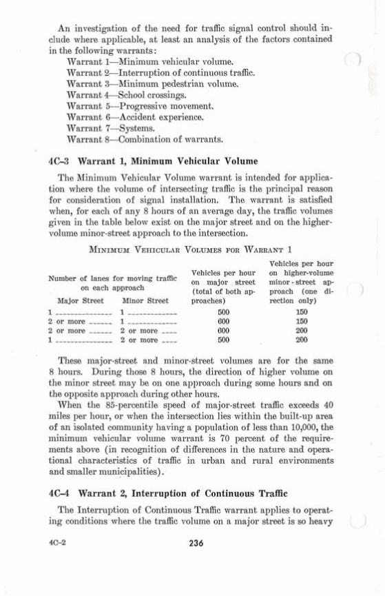
The Minim~un Vel~icular Volume warrant is intended for applica- tion where the volume of intersecting traffic is the principal reason for consideration of signal installation. The warrant is satisfied when, for each of any 8 hours of an average day, the traffic volumes given in the table below exist on the major street and on the higher- volume minor-street approach to the intersection.
Vehicles per hour Vehicles per hour on higher-volume
Number of lanes for moving traffic ,, major street minor - street ap- I
on each approach (total of both ap- proach (one di- 1 Major Street Minor Street proaches)
1 --------------- 1 ------------- 500 2 or more -----, 1 ------------- 600 2 or more ------ 2 or more ---- 600 1 --------------- 2 or more ---- 500
rection only) 150 150 200 200
These major-street and minor-street volumes are for the same 8 hours. Dnring those 8 I~ours, the direction of higher volume on the minor street may be oil one approach during some hours and on the opposite approach during other hours.
When the 85-percentile speed of major-street traffic exceeds 40 miles per hour, or when the intersection lies within the bnilt-up area of an isolated community having a population of less than 10,000, the ininimuin vehicular volnme warrant is 7'0 percent of the require- ments above (in recognitioil of cliffereilces in the nature and opera- tional characteristics of traffic in urban and rural environments and smaller municipalities).
4C-4 Warrant 2, Interruption of Continuous Traffic
The Interruption of Continuous Traffic warrant applies to operat- ing conditions where the traffic volume on a major street is so heavy i

that traffic on a minor intersecting street suffers excessive delay or hazard in entering or crossing the major street. The warrant is satisfied when, for each of any 8 hours of an average day, the traffic
' ) volumes given in the table below exist on the major street and on the higher-volume minor-street approach to the intersection, and the signal installation will not seriously disrupt progressive traffic flow.
Vehicles per hour VehicIes per hour on higher-volume
Number of lanes for moving traffic on major street minor - street ap- on each approach (total of both ap- proach (one di-
Major Street itfinor Street 1 --------------- 1 ------------- 2 or more ------ 1 ------------- 2 or more ------ 2 or more ---- 1 --------------- 2 or more ----
rection only) 75 75 100 100
These major-street and minor-street volumes are for the same 8 hours. During those 8 honrs, the direction of higher ~ o l ~ ~ m e on the minor street may be on one approach during some hours and on the opposite approach during other hours.
When the 85-percentile speed of major-street traffic exceeds 40 miles per hour, or when the intersection lies witliin the built-up area
, of an isolated community having a population of less than 10,000, the interruption of continnous traffic warrant is 70 percent of the re- quirements above (in recognition of differences in the nature and operational characteristics of traffic in urban and rural environments and smaller municipalities).
4C-5 Warrant 3, Minimum Pedestrian Volume
The Minim~~m Pedestrian Volume warrant is satisfied when, for each of any 8 hours of an average day, the following traffic volumes exist :
1. On the major street, 600 or more vehicles per hour enter the intersection (total of both al~proacl~es) ; or where there is a raised median island 4 feet or more in width, 1,000 or more vehicles per hour (total of both approaches) enter the intersection on the major street; and
2. During the same 8 hours as in paragraph (1) there are 150 or more pedestrians per hour on the highest volume crosswalk crossing the major street.
When the 85-percentile speed of major-street traffic exceeds 40 miles per honr, or when the intersection lies within the built-up area of an isolated community having a population of less tllan 10,000, the miniinum pedestrian volume warrant is 70 percent of tlie re-
quirements above (in recognition of differences in the n a t ~ ~ r e and operational ccharacteristics of traffic in urban and rural environments and smaller mnnicipalities) . I
A signal installed nnder this warrant at aA isolated intersection should be of the traffic-actuated t , yp with pus11 buttons for pedes- trians crossing the main street. If snch a signal is installed at an intersection within a signal system, it should be eq~~ipped and op- erated with control devices which provide proper coordination.
Signals installed according to this warrant shall be equipped with pedestrian indications conforming to requirements set forth in other sections of this Manual.
Signals may be installed at nonintersection locations (mid-block) provided the requirements of this warrant are met, and provided that the related crosswalk is not closer than 150' to another estab- lished crosswalk. Curbside parking should be prohibited for 100' in advance of ancl 20' beyond the crosswalk. Phasing, coordination, and installation must conforii~ to standards set fortli in this Manual. Special attention sliould be given to the signal head placement and the signs and markings used at nonintersection locations to be sure drivers are aware of this special application.
4C-6 Warrant 4, School Crossing A traffic control signal may be warranted at an established school
crossing when a traffic engineering study of the frequency and ad- equacy of gaps in the vehicular traffic stream as related to t.he num- ber and size of groups of school children at the school crossing shows that the number of adeqnate gaps in the traffic stream during the period when the children are using the crossing is less than the number of minutes in the same period (sec. 7A-3).
When traffic control signals are installed entirely under this warrant :
1. Pedestrian indications shall be provided at least for each cross- walk established as a scliool crossing.
2. At an intersection, the signal normally should be traffic-actuated. As a minimum, it sliould be semi-traffic-act~~ated, bnt full actuation wit11 detectors on all approaches may be desirable. Intersection in- stallations that can be fitted into progressive signal systems may have pretimed control.
3. At non-intersection crossings, the signal should be pedestrian- actnated, parking and other obstructions to view should be pro- hibited for at least 100 feet in advance of and 20 feet beyond the crosswallr, and the installation sliould include suitable standard signs and pavement markings. Special police snpervision and/or enforce- ment sliould be provided for a new non-intersection installation.
4C-7 Warrant 5, Progressive Movement
Progressive movement control sometimes necessitates traffic signal iiistallatiolis at intersections where they would not otherwise be warranted, in order to maintain proper grouping of vehicles and effectively regulate group speed. Tlie Progressive Rtovement war- rant is satisfied when : 1. On a one-way street or a street which has predominantly uni-
directioiial traffic, the adjacent signals are so far apart that they do not ~rovide the necessary degree of vehicle platooning and speed control, or
2. On a two-way street, adjacent signals do not provide the neces- sary degree of platooning aizcl speed control and the proposed and adjacent signals could constit~1t.e a progressive signal system.
Tlie installation of a signal according to this warrant should be based on the 85-percentile speed unless an engineering study indi- cates that another speed is niore desirable.
The installation of a signal according to this warrant should not be coilsidered where tlie resultant sigllal spacing would be less than 1,000 feet.
4C-8 Warrant 6, Accident Experience
The Accident Experience warraiit is satisfied when : 1. Adequate t r id of less restrictive remedies wit11 satisfactory
observance and enforcement has failed to reduce the accident fre- quency ; and
2. Five or more reported accidents, of types susceptible of correc- tion by traffic signal control, have occurred within a 12-montli period, each accident involving personal injury or property damage to an apparent extent of $100 or more ; and
3. There exists a ~~olunie of .rrelzicular ancl pedestriaiz traffic not less than 80 percent of tlie requireiiieats specified either in the inimi- nium vehicular ~rolunie warrant, the interruption of continuous traffic warrant, or the ininiinuin pedestrian voluine warrant ; and
4. The signal installation will not seriously disrupt progressive traffic flow.
Any traffic signal installed solely oil the Accideiit Experience war- rant slzonld be senii-traffic-actuated (wit11 control devices which pro- vide proper coorcliiiatioii if installed at an intersection within a coordinatecl system) and iiorizially should be fully traffic-actuated if installed at an isolated intersection.
4C-9 Warrant 7, Systems Warrant
A traffic signal installation at some intersections iiiay be warraiited to encourage conceiztltmtioiz and organization of traffic flow networks.

The Systems warrant is applicable when the common intersection of two or more major r o~~ te s has a total existing, or i~nmediately pro- jected, entering volume of at least 800 vehicles dnring the pealr hour of a typical meelrday, or each of any five hours of a Satt~rday and/or 1 Sunday.
A major route as used in the above warrant has one or more of the following characteristics :
1. It is part of the street or highway system that serves as the principzl network for througli traffic flow ;
2. It connects areas of principal traffic generation ; 3. It includes rural or suburban liighways outside of, entering or
traversing a city ; 4. It has surface street freeway or expressway ramp terminals; 5. It appears as a major route on an official plan such as a major
street plan in an urban area traffic and transportation study.
4C-10 Warrant 8, Combination of Warrants I n exceptional cases, signals occasio~ially may be justified where
no single warrant is satisfied but where two or niore of Warrants 1, 2, and 3 are satisfied to the extent of 80 percent or more of the stated values.
Adequate trial of other remedial measures which cause less delay and inconvenience to traffic should precede installation of signals under this marmnt. 1
4C-11 Factors Governing Selection of Type of Control The principal factors that may lead to the favorable consideration
of traffic-actuated control in the selection of the type of signal con- trol include :
1. Low, fluctuating or unbalanced traffic volumes. 2. High sicie street traffic volunies and delays only during the
peak hours. 3. Tlie pedestrian or accident warrant is the only warrant which is
met. 4. The installation is to provide for one-way movement of two-
way traffic. 5. The installation is at a non-intersection location.
4C-12 Pedestrian-Actuated Control Operation of traffic-actuated signals must take into consideration
the needs of pedestrians as well as vehicular traffic. This can be ac- coinplislied in the following ways :
1. 1,Vlien pedestrian signals are not warranted in conjunction with a traffic-actuatecl signal installation (sec. 4D-3) but where occasional
pedestrian movement exists and there is inadequate opportunity to cross without undue delay, pedestrian detectors shall be installed and operated as prescribed in sections 4D-6 and 7.
2. When pedestrian signals are izot otherwise warranted but a pedestrian movement exists which would izot have adequate crossing time during the green interval, pedestrian signals and detectors shall be installed and operated as prescribed in sections 4D-6 and 7.
3. When pedestrian signals are warranted and installed in con- junction witlz a traffic-actuated signal, the operation slzould follow the patterns described in sections 4D-6 and 7.
D. PEDESTRIAN SIGNALS
4D-1 Pedestrian Signal Indications Pedestrian signal indications are special types of traffic signal in-
dications intended for the exclusive purpose of controlling pedes- trian traffic. These indications consist of tlze illnminated words WALK and DONT WALK.
4D-2 Meaning of Pedestrian Indications The meanings of pedestrian signal indications are as follows : 1. The DONT WALK indication, steadily illuminated, means that
a pedestrian shall not enter the roadway in the direction of the in- dication.
2. The DONT WALK indication, while flashing, means that a pedestrian sliall izot start to cross tlze roadway in the direction of the indication, but that any pedestrian who has partly conlpleted his crossing during the steady TVALIZ indication shall proceed to a side- walk, or to a safety island.
3. The TVALIS. indication, steadily illuminated, means that pedes- trians facing the signal indication may proceed across the roadway in the direction of tlze indication.
4. The TVALIZ indication, while flashing, means that there is a possible conflict of pedestrians witlz vehicles.
4D-3 Applications of Pedestrian Signal Indications Pedestrian signal indications shall be installed in conjunction ~ v i t l ~
vehicular traffic signals (wlzich meet one or more of the traffic signal warrants previously set fortlz) under any of the following con- ditions :
1. Wlzen a traffic signal is installed under the pedestrian volume or school crossing warmnt.
2. IVl~en an exclusive interval or phase is provided or made avail- able for pedestrian movement in one or more directions, wit11 all conflicting vellicular movements being stopped.
3. TVllen vehicular iildicatioas are not visible to peclestrians such as on one-way streets, at "T" intersections; or when the vehicular inclications are in a positioil which moulcl not adeq~~ately serve pedestrians.
4. At established school crossings at intersections signalized under any warrant.
Pedestrian signal indications also may be installed under any of the follo~ving conditioils :
1. TVllen any volume of pedestrian activity requires use of a pedes- trian clearance interval to i1liilimize vehicle-pedestrian conflicts or wvlleiz it is necessary to assist pedestrians in making a safe crossing.
2. When multi-phase indications (as wit11 split-phase timing) woulcl tend to confuse pedestrians guided only by vehicle signal indications.
3. When pedestrians cross part of the street, to or from an island, during a particular interval (where they should not be permitted to cross another part of that street during any part of the same interval).
4D-4 Design Requirements
Design requirements for pedestriail signals include the following: 1. Pedestrian indications sl~ould attract the attention of, and be
readable to, the pedestrian (both day and night) at all distances )
from 10 feet to the fall width of the area to be crossed. 2. All pedestrian indications shall be rectangular in shape and
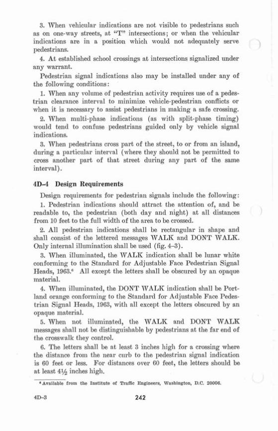
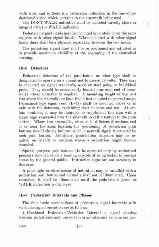
shall coilsist of the lettered messages WALK and DONT WALK. Only internal ill~unination sllall be used (fig. 4-3).
3. T;Vlleil illuminated, the TVALIC indicatioil shall be lunar white conforming to the Standard for Adjustable Face Pedestrian Signal Heads, 1963.= All except the letters shall be obscured by an opaque material.
4. When illuminated, the DONT WALK indicatioil shall be Port- land orange confori~~ing to the Stanclarcl for Adj~lstable Face Pedes- trian Signal Heads, 1963, with all except the letters obscured by an opaque material.
ti. When not illunziilated, the WALK and DONT \TALI< messages shall not be distinguishable by pedestrians at the far end of the cross~valk they control.
6. The letters shall be at least 3 inches high for a crossing where the distance from the near curb to the pedestrian signal indication is 60 feet or less. For clistances over 60 feet, the letters slzonld be at least 4% inches high.
EAvailable from the Institute of Traffic Engineers, Wasl~ington, D.C. 20006.
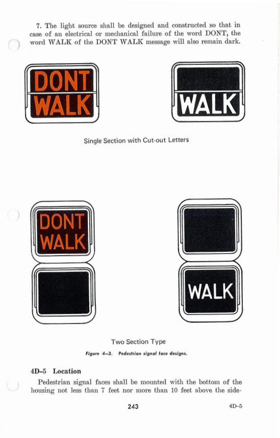
7. The light source shall be designed and constructed so that in case of an electrical or inechanical failure of the word DONT, the word WALK of the DONT WALK message will also reinain dark.
I WALK' Single Section with Cut -out Letters
WALF
WALK
T w o Section Type
Figure 4-3. Pedestrian signal face designs.
4D-5 Location Pedestrian signal faces shall be mo~ulted wit11 the bottom of the
housing not less than 7 feet nor more than 10 feet above the side-
walk level, and so there is a pedestrian indication in the line of pe- destrians' vision which pertains to the crosswalk being used.
The DONT WALK indication sliall be mounted directly above or 1 integral with the TVALIC indication.
Pedestrian signal heads may be inountecl separately or on the same support with other signal heads. 7Vheii mounted with otlier signal heads tliere shall be a physical separatioii between the two heads.
The pedestrian signal head shall be so positioned and adjusted as to provide inaxinlum visibility at the beginning of the controlled crossing.
4D-6 Detectors I
Pedestrian cletectors of the push-botton or other type shall be 1- 1
designated to operate on a c i rc~~i t not to exceed 18 volts. They niay be mounted on signal standards, wood or steel poles, or individual i posts. They shonld be conveniently located near each end of cross- walks where act~~ation is requirecl. A mounting height of 3% to 4 feet above the sidewallc has been found best adapted to general usage. Perinanent-type signs (sec. 2B-35) sliall be mounted above or in unit with the detectors, explaining their purpose and use. At cer- tain locations, it may be desirable to snpplement this sign with n
I ' I
larger sign suspended over the side\valk to call attention to the push -
1 button. TV11ere two crosswallcs, oriented in different directions, end at or near the sanie location, the positioning of pedestrian push buttons slzonld clearly indicate ~vhich crosswalk signal is actuated by each push botton. Aclditional push-button detectors 'may be re- quired on islands or ineclians ~vhere n pedestriaiz might become stranded.
Special purpose push-buttons (to be operated only by authorized persons) should include a lionsing capable of being locked to prevent access by the general public. Instrnction signs are not necessary in this case.
A pilot light or other means of indication may be installed with a l~edestrian push button and norilzally shall not be illuminated. Upon actuation, it shall be illuniinated until the peclestrian's green or WALK indication is displayed.
4D-7 Pedestrian Intervals and Phases
The four basic coinbinations of pedestrian signal intervals wit11 1
~7eliicular signal operation are as follows : ,
1. Combined Pedestrian-Vehicular Interval-a signal phasing wherein pedestrians may use certain cross~+allrs ancl veliicles are per-
mitted to turn across tlzese crosswalks (tlie pedestrian indications slzall be flaslzing WALII& o l- < 4- ' , LLI , ' 1- IC) .
' ) 2. Exclusive Crosswalk Interval-a signal phasing ~vllereiii pedes- trians may use certain crosswalks b ~ l t vellicles are not permitted to move across these cross~vallrs during tlze pedestrian movement (the pedestrian indication sllall be steady JVALII) .
3. Leading Pedestrian Interval-a signal phasing wherein an ex- clusive pedestrian interval, in advance of the vehicular indication slzall be steady IVALII. When the leading pedestrian interval is terininatecl, and a combined pedestrian-vehic~~lar interval begins, the TTTALIZ indication inay begin to flaslz.
4. Exclusive Pedestrian Phase-a signal phasing wherein pedes- trians inay proceed to cross tlze intersection in any direction dt~riizg an exclusive phase Jvllile all velzicles are stopped (the pedestrian indication s11a11 be steacly TVALIZ) .
Pedestrians should be assnred of stlfficient tiine to cross the road- way at a signalized intersectioiz. Where traffic signals are of the actuated type, control eq~lipinent shoulcl provide sufficient pedestrian crossing time when there has been a pedestriaiz act~~ation and tlze minimum vel~iczllar time is less tlzaiz that needed by tlze pedestrians. Where traffic signals are not of the vehicle-actuated type, pedestrian actuation nlay be used to provide sufficient pedestrian crossing time,
\ or the velzic~~lar time should be adjusted to provide the crossing time ' needed by pedestrians.
Under normal conditions, the TVALIC interval should be a t least 7 seconds, so that pedestrians mill lzave adequate opportunity to leave tlze curb, before the clearance interval is sl~own. However, the TVALII interval itself need not eq~lal or exceed the total crossing time calculated for the street ~vidtlz, as many pedestrians mill com- plete their crossing during the flashing DONT IVALII clearance interval.
A pedestrian clearance interval shall always be provided where pedestrian signal indications are usecl. It slzall consist of a flashing DONT TTALIC inclicatioiz. Tlze duration should be su~fficient to al- low a pedestrian crossing in the crosswallr to leave the curb and travel to the center of tlze farthest traveled lane before opposing ve- hicles receive a green inclication (nornzal walking speecl is asstuned to be 4 feet per seconcl). On a street with a ilzedian at least 6 feet in ~vidtlz, it may be desirable to allow only enough peclestrian clear- ance tiine on a given phase to clear the crossing from tlze curb to the meclian. I11 tlze latter case, if the signals are peclestriaa-acttlated, an aadclitional detector shall be provided on the isand (sec. 4D-6).
14Tlze11 a traffic signal iizstallatioiz is being operated as a flashing device, the pedestrian indications shall not be illuminated.
E. OTHER HIGHWAY TRAFFIC SIGNALS
4E-1 Hazard Identification Beacon \ i
A Hazard Identification Beacon is one or more sections of a stand- ard traffic signal head ~vitlz a flashing CIRCULAR YELLOW indi- cation in each section. Typical applications include :
1. Obstructions in or immediately adjacent to the roadway. 2. Suppleinental to advance warning signs. 3. At mid-block crosswalks. 4. At intersections where warning is required. 5. Sup~lemental to regulatory signs, except the STOP, YIELD
and DO NOT ENTER signs.
A Hazard Identification Beacon sllall be used only to supplement an appropriate vanl ling or regulatory sign or marker. The beacon shall not be inclttded within the border of the sign.
Hazarcl Identification Beacons, when used at intersections, shall not face conflicting vel~icular approaches.
4E-2 Speed Limit Sign Beacon
A Speed Limit Sign Beacon is two CIRCULAR YELLOW lens sections each having ,z visible cliaineter of not less than six inches, as an alternate, one or more CIRCULAR YELLOW lenses, each having a visible diameter of not less than eight inches. Where two lenses are used, they shall be vertically aligned, and they shall be alterilately flashed.
A Speed Limit Sign Beacon is intended for use with a fixed or variable speecl limit sign. Wlzere applicable, a flashing speed limit beacon (wit11 an appropriate accoinpsnying sign) may be used to indicate that the speed liinit shown is ill effect.
4E-3 Intersection Control Beacon
An Intersection Control Beacon consists of one or inore sections of a standard traffic signal head, having flashing CIRCULAR YELLOW or CIRCULAR RED indications i11 each face. They are instdlecl and are used only at an intersection to control two or inore directions of travel. Supplemental indications inay be needed on one or inore approaches in order to provide adeqnate visibility to ap- proaching motorists.
Intersection Control Beacons are intended for use at intersections 8
where traffic or physical conditions do not justify conventional traffic signals but wvl~ere high accident rates indicate a special hazard.
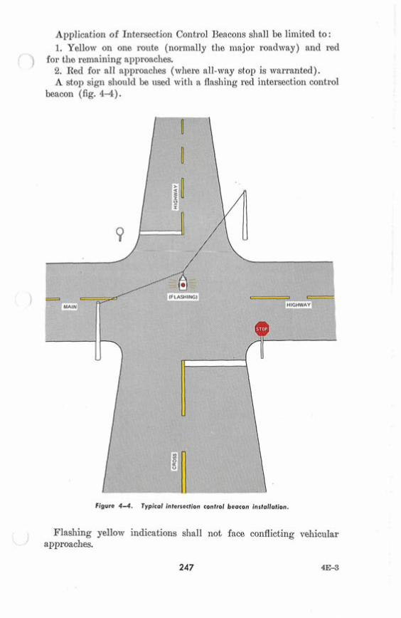
Application of Intersectio~l Control Beacons slzdl be limited to : 1. Yellow on one route (normally the major roadway) and red
) for the remaining approaches. 2. Red for all approaches (~vliere all-way stop is warranted). A stop sign should be used wit11 a flasl~ing red intersection control
beacon (fig. 4-4).
Figure 4-4. Typical intersection control beacon installation.
Flashing yellow indications sllall not face coilflicting vehicular approaches.
4E-4 Stop Sign Beacon
A Stop Sign Beacon is one or two sections of a standard traffic signal head with a flashing CIRCULAR RED indication in each section. Where t\vo lenses are used, they sl~all be the 8" nominal diameter size, aligned Izorizontally and they shall be flaslzecl siinul- taneously. Where a single lens is used, it izzay be eitlzer 8" or 12" nominal diameter.
Tlze bottoin of the housing of a Stop Sign Beacon shall be not less tlzan 12 nor inore than 24 inches above the top of a stop sign (sec. 2 B 4 ) .
4E-5 General Design and Operation of Beacons
Flaslzing beacon units and their mounting shall follow tlze general clesign specifications for traffic control signals, which shall include the followiizg essentials :
1. Each signal unit lens shall have a visible diameter of not less than 8 inches, except for Speed Liinit Sign BBacons described in section 4E-2.
2. TVhen ill~~nzinated, the beacon shall be clearly visible (to all clri~ers it faces) for a distance of at least 1/4 mile under normal atmosplzeric conditions unless otherwise plzysically obstructed.
3. The red and yellow lens colors slzall be in accordance mitlz the requirements of tlze Standard for Adjustable Face Velzicle Traffic Coiltrol Signal Heads, Revised 1970.7
All flashing contacts should be equipped wit11 filters for suppres- sion of radio interference.
Beacons shall be flashed at a rate of not less tlzaiz 50 nor nzore tlzan 60 times per minute. Tlze illuminated period of each flaslz slzall not be less tlzan one-half and not inore than two-thirds of the total cycle. When lzazarcl identificatio~z beacons have Inore than one sec- tion, they may be flashed alternately.
Beacons slzould be operated only during tlzose hours when tlze hazard or regulation exists.
A flashing yellow beacon interconnected with a traffic signal con- troller nzay be used mitlz an advance traffic signal wnrning sign (sec. 2C-16).
If a 150 watt lamp is used in a 12" lens flashing yellow beacon and tlze flashing yellow is so bright as to cause excessive glare dnring aigllt operation, an automatic dimming device should be used to re- dnce the brilliance during night operation.
lAvailable from the Institute of Traffic Engineers, Washington, D.C. 20006.
4E-4 248
4E-6 Hazard Identification Beacon Location The hazard or other condition warranting Hazard Identification
Beacons slzould largely govern their location wit11 respect to the roadway. If used alone aizd locatecl at the roadside, tlze bottom of tlze beacon unit sl~all be at least 8 feet aizd izot more t h m 12 feet above the pavement. If suspended over the roadway, tlze clearance above the payenlent shall izot be izlore than 19 feet nor less than 15 feet. 111 no case shoulcl they be mounted on pedestals in the roadway unless tlze pedestal is ~vitl~iiz tlze confines of a traffic or peclestrian island. 7;Vhere an obstrt~ctioa is in or adjacent to tlle roadway, illumination of tlze lower portion or the beginning of tlle ~ b s t ~ ~ ~ c t i o n , or a sign on or in front of tlle obstructioiz is desirable, in addition to the beacon.
4E-7 Intersection Control Beacon Location An Intersection Control Beacon is generally suspended over the
center of an intersection; however, it may be used at other suitable locations. If snspended over tlle roaclway the clearance above the pavement sllall be at least 15 feet but not more than 19 feet. If pedestal mounting is used, tlle bottoi~i of tlze signal llead shall be at least 8 feet but not inore tlzan 15 feet above the pavement. I n no case shoulcl it be mo~ulted on a pedestal in the roadway unless the pedestal is witlzin the confines of a traffic or pedestrian island.
4E-8 Lane-use Control Signals Lane-use control signals are special overllead signals having indi-
cations used to perinit or prohibit the use of specific lanes of a street or higllway or to indicate the impending prohibitions of use. Instdlations are clistingnislzecl by placement of these special signals over a certain lane or lanes of the roadway and by tlzeir distinctive shapes aizd symbols. Snpplementary signs are often used to explain their meaning and intent.
Lane-use control signals are most coiilinonly used for reversible- lane control. This type of control slzould be used only when a competent engineering s t ~ ~ d y sllows that tllere is need ancl also that the ~laizizecl operation is practicable. Reversible-lane operation may be appropriate at toll-boot11 areas.
Lane-use control signals also may be used where there is 110 intent or need to reverse lanes. Some applications of this type are :
1. 011 a freeway, wllere it is clesired to keep traffic out of certain lanes at certain hours to facilitate tlle merging of traffic from a rainp or other freeway.
2. 011 a freeway, near its terizlinus, to indicate a lane that ends. 3. On a freeway or long briclge, to indicate a lane whiclz may be
temporarily bloclrecl by sm accident, breakdown, etc.

4E-9 Meaning of Lane-use Control Signal Indications The meanings of lane-use control signals are as follows : 1. A steady DOTTNTVARD GREEN ARROTT means that a )
driver is pennittecl to drive in the lane over ~vl~ich the arrow signal is located.
2. A steady YELLOW X ineans that a driver should prepare to vacate, in a safe wanner, the lane over whicll the signal is located beca~~se a lane control cl~ange is being made, and to avoid occ~~pying that lane xvhen a steady RED X i s displayed.
3. A flaslling YELLOW X ineans that a driver is perinitted to use a lane over which the signal is locatecl for a left turn, using proper caution.
4. A steady RED X ineans that a driver s l ~ d l not drive in the lane over which the signal is located, and that this indication shall inodify accordingly the meaning of all other traffic controls present. The driver shall obey all other traffic controls and follow normal safe driving practices.
4E-10 Design of Lane-use Control Signals All lane-use control signal indications shall be in units vith
rectangular faces. Nomian1 ininiin~nn height and width of each face shall be 12 inches for typical applications. However, other sizes wit11 message recognition distances appropriate to signal spac- ing inay be employed for unusual applications.
Each lane to be reversed shall liave signal faces with a DOIVN- WARD GREEN ARROTV on an opaque background, and a RED X symbol on an opaque backgrouncl. Signal faces with a YELLOW X syinbol on an opaqne background may be provided for operation as described in section 4E-12.
Each nonreversible lane iininediately adjacent to a reversible lane shall have a DOIVNTVARD GREEN ARROTV displayecl to traffic traveling in the perinittecl direction ancl a RED X syinbol clisplayed in the opposite direction. Other nonreversible lanes on any street so controllecl inay also be pro~idecl ~vitll these inclications.
The inclications provided for each lane inay be in separate units or inay be superimposed in the same ulnit. TVhen in separate units, the RED X syinbol shall be on the left, the YELLOTV X syinbol, if used, shall be in the middle nncl the DOTVNIVARD GREEN ARROW syinbol shall be on the right.
The color of lane-nse control signal indications shall be clearly visible for 1/4 inile at all tiines ~~ilcler norlnal atinospheric conditions, unless otherwise physically obstructed.
The visibility angle of the lane-use control signal slzall be at least as great as that specified for the standard circnlar traffic signal (sec. 4B-11).
4E-11 Location of Lane-use Control Signals
Lane-use control sigiial nnits sliall be locatecl approxiinately over
) the center of the lane controlled. If the area to be coiltrollecl is inore tllan 1/4 mile in leiigtlz, or if
911e vertical or horizontal aligilmeat is curved, iiitei~nediate lane-use control signal iiiclicatioizs shdl be placed over each coiitrolled lane at freclueiit intervals. This placemeat shall be sucli tliat a illotorist will at all times be able to see at least one iiiclicatioa, and preferably two (dne to the possibility of a burllout of a single iadication) along tlie roadway, a i d will have a definite indication of the lanes specifically reserved for his use.
All lane-use coiltrol iildications slla11 be located i11 a straigl~t line across tlie roadway at right angles to tlie roaclmay alignment.
The bottom of ally lane-use control signal unit slzall be not less tliaa 15 feet nor inore thaa 19 feet above the pavement grade.
On roadways having iiitersectioils coiitrolled by traffic signals, the laiie-use control iildication shall be placecl sufficiently far in aclvance of or beyond sucll traffic signals to pre~~eiit them from being mis- coilstruecl as traffic coiitrol sigaals. T~velve-inch lenses inay be neces- sary in the intersectioil traffic coiltrol signals to aid i11 distinguishing between the two types of signals.
, 4E-12 Operation of Lane-use Control Signals
All reversible-lane control signals sliall be coordinated and wired to a inaster control which will operate so as to permit signal indications for each directioii iii any of tile reversing laiies to change from a steady RED X to a DOIVNTVARD GREEN ARROW or from a DOIVNTYARD GREEN ARROW to a steady YELLOW X wheil used, a i d tl~eii to a steacly RED X. Tlie showing of a DOTVN- WARD GREEN ARROW or steacly YELLOTV X or any combina- tion thereof, in both directions over tlie saine laiie, sliall be guarded agsiilst by electrical interloclr.
During cllange-over periods, a steady YELLOW X iildicatioii may be usecl to ilotify traffic in a reversible lane to prepare to vacate the lane. Alternatively the steady RED X limy im~liediately follow the terminatioii of the steady DOIVNJVARD GREEN ARROW, ancl in this case a clearance periocl of appropriate lengtli shall be provided, during which the steacly RED X shall be shown in both clirections over the lane before the steady DOTVN\VARD GREEN ARROW iiiclicatioil is slio~vn for traffic fro111 the opposite direction.
Where feasible, a flashing YELLOTV X for both clirections nzay be used over a lane to perinit use of that lane for left turns, with clue cautioii.
The type of control provided for reversible-lane operation should be suclz as to permit either automatic or manual operation of the lane-use control signals. If an automatic system is usecl, a manual control to over-ride the automatic control shall be provided.
When used, lane-use signals shall be operated contii~nously.
4E-13 Traffic Signals at Drawbridges
Signals installed at drawbridges are a special type of highway traffic sigilal, the purpose of ~vl~icll is to notify traffic to stop because of the road closure rather tlian alternately giving the right-of-way to conflictiilg traffic movements. They are inan~~ally operatecl in coordination with the opening and closing of the drawbridge, and wit11 the operation of gates, barriers, or otlzer devices used to warn, control ailcl stop vellicles. Unlike traffic control signals, drawbridge signals may be operated freqnently or at extreinely infreqt~ent inter- vals depending upon the nature of the pl~ysicd conditions and water- way traffic.
4E-14 Application of Drawbridge Signals
Drawbridge signals shall always be used in coiljunction with gates and other types of protection coinmonly eillployed at drawbridges.
4E-15 Design of Drawbridge Signals
The signal heads and mo~ultings of drawbridge signals sl1a11 fol- low the staildard design specifications for traffic control signals. Drawbridge signals inay be suppleineated with bells to provide ad- ditional wariling to drivers and pedestrians.
Nominal 8-inch signal indications are standard. However, if pre- vailing approaclz speecls are in excess of 25 miles per lloour, or when considerations such as roadway width or geoinetrics, signal location, conflicting lights or objects in the backgronnd, etc., iilclicate the need for greater signal effectiveness, signal heads ~vith 12-iach diameter lenses ancl 100-watt or larger lamps should be providecl.
Where physical conclitions prevent a driver (traveling at the 85 percentile approach speed) froill having a continuous view of at least one signal indication for approximately 10 seconds before reachiag the stop line, an auxiliary device slzall be provided. This device inay be either an auxiliary signal or a DRAWBRIDGE AHEAD sign with a Hazard Identificatioil Beacon interconnected with the clrawbridge controller.
A DRAWBRIDGE AHEAD sign shall always be used at the proper clistailce fro111 the drawbridge to give aclvance warning to izzotorists, except in nrban conditions ~vl~ere such sig-ning would not
be feasible. Such signs shall be supplemented by a Hazarcl Identi- fication Beacon (sec. 4E-1) under the conditioiis described above as well as for other conditioiis. It is clesirable to control this beacon froin the briclge-tender's station so it will be flashed only when needed to \van1 of drawbridge operation.
Since drawbridge operation covers so wide a range of time periods between openings, two types of signals are provided and engineering judgment must be exercised in determining which to use tuider par- ticular circumstalices. The first type consists of the standard three- color (red, yellow, ancl green) traffic signal indications, generally to be used when drawbridge operation is quite frequent. The second type consists of two recl signal indications in vertical array separated by a STOP HERE ON RED sign (sec. 2B-35).
4E-16 Location of Drawbridge Signals
Two signal indications sllall be provided for each approach to the inovable span. One signal shall be at the riglit side of the roadway, ancl the other at the left side or over the left half of the roadway, directly across the roaclway froin the right hand indication. Inso- far as practicable, the height and lateral placement of signals at drawbridges slioulcl conforin to the requirements for other traffic control signals. They should ordinarily be from 20 to 50 feet in advance of the first gate or other barrier.
4E-17 Operation of Drawbridge Signals
Signals at drawbridges shall be interconnected with the draw- bridge gates or other warning or control devices, and with the movable span, so that signals, gates and movable span are coiitrolled manually by the bridge tender t l iro~~gh an interlocked switching con- trol. Signals on adjacent streets and highways sliould be inter- connected with the drawbridge control, if indicated by engineering considerations. If the drawbridge is close to a railroad grade cross- ing and there is a possibility that traffic may be stopped on the crossing as a result of the bridge opening, a suppleinentary traffic signal coordinated with the drawbridge signal should be provided to prevent traffic from being stopped on the railroad crossing. Ex- treme care should be used in planning such signal installations to avoid creating confusioii or hazardous conditions.
TVhere bridge openings are frequent and the three-color type of signal is used, the green signal slid1 be illuminated at all times be- tween bridge opening periods. TYlieii the bridge is to be opened, the signal shall change to yellow for a predetermined interval (normally approxiniately 3 to 5 seconds) and shall change to red not less than 15 seconds before the gates or other devices begin to operate to
close the roadway. TVhile the gates are closed, the signals shall sllo~v a coiltiiluous recl indication. After the briclge has been closecl and the gates have been openecl, the signal i~lclicatioils shall retar11 to I steady green. The sequence of signal, gate ancl bridge operatioil shall be antomatic, through interconilection with the briclge control mechanism. The duration of each signal iilclication interval, except the yellow interval, shall therefore be controllecl by the bridge operation.
Where briclge openiiiags are less frequent or where for some other reason the double-recl type of signal iilstallation is selected, the signal shall not be ill~uininatecl between briclge opeaing periods. TVhen the briclge tender initiates the briclge opening proceclure, the signal shall start alternate flashing of the red indications. After a ininirn~un periocl of approximately 20 seconcls, the gates may be lowered. TVhen the briclge has been again closecl and the gates have been raised, the recl signal inclications shall be discoatinued.
T47lzen a Hazard Iclentification Beacon is usecl with the DRAW- BRIDGE AHEAD sign (sec. 4E-15) i t should be interconilectecl with the clmmbriclge coiltroller in such a inailner as to begin opera- tioil snfficiently in advance of the beginning of the briclge opeiling signal sequence as to ~ v a n l drivers that they will ellcounter a recl signal or ~rehicles stoppecl by the signal. It may frequently be cle- sirable to continue this beacon in flashing operation after the draw- briclge cycle has been coinpletecl tultil all stoppecl vehicles have started to move and traffic is again flonliilg freely.
4E-18 Traffic Signals for Emergency Vehicle Movements
An emergency-traffic signal is a special aclaptation of a traffic con- trol signal to obtain the right-of-way for ail autl~orizecl eiiiergency vehicle. A n emergency-traffic signal inay be installecl a t a locatioii that cloes not meet the ~varrants prescribed for the various types of other traffic signal ii~stallatioi~s. It ]nay be iilstallecl at an inter- section or a t other locatioils where there is clirect access froin a bnilcling housing the emergency vehicle.
Right-of-way for emergency vehicles a t sigilalizecl locations shall be obtainecl as specified in section 4B-22.
4E-19 Applications of Emergency-Traffic Signals
A t ail unsignalizecl location, an emergency-traffic signal may be justifiecl if aclecluate gaps in traffic clo not exist to perinit safe eiltrailce of enzergeacy vehicles, or the stopping sight clistailce for vehicles approaching on the througll street is insufficient to permit safe entrance of eniergency ve1lic.les.
Tlze sight clistaizce cletermination is based on the location of the visibility obstruction for the critical approacll lane for each street or clrive, ancl the posted or 85th percentile speecl on the tl~rouglz
' street, whichever is higher. I f warrants for a traffic control signal (sec. 4C) are met, a signal
izorinally ~ 1 1 0 ~ 1 ~ 1 be installed to the stanclards reqnirecl for that type of sigizal (sec. 4B).
The use of emergency-traffic s ignds to perlnit direct access to a street froizi a building lzousing emergency equipment is optional.
4E-20 Design of Emergency-Traffic Signals
Except as specifiecl in this section, a traffic control signal for emergency vehicle moveinents shall meet tlze reqnirelliellts of this R'lan~~al.
A t least oize signal face should be located over the roadway. A sign, legible a t all times, bearing tlze legeild EBfERGENCY
SIGNAL sllould be inouilted adjacent to each sigizal face. A Hazard Ideiztification Beacon niay be installecl in aclvaizce of an
emergency-traffic sigizal. Such beacon shall be acco~lzpaizied by an appropriate warning s ign The clesign ancl location of tlze beacon s h d l conforin to the stanclards specifiecl in sections 4E-1 and 4E-5.
A miniiliun~ of oize signal face shall face the clirectioiz of approach : of the emergency vehicle.
4E-21 Operation of Emergency-Traffic Signals
As a ininiinuiz~, the ii~clications, sequence ancl inanner of operation of an enzergency traffic control signal installed a t a inid-bloclc loca- tioil shall be as follows :
1. The signal indication, between emergency vehicle actuations, shall be either a steady green or flashing yellow.
2. There shall always be a steacly yellow chaage indication shown to traffic on the street, but a change illclicatioiz is not requirecl for the emergeizcy vehicle clrirreway.
3. There s h d l be a steady recl signal indication for traffic on the street. Tlze cluration of the recl period shoulcl be cleterminecl 011 the basis of on-site test run-time studies, but shoulcl no r~nd ly not ex- ceed 1.5 tiizles the emergency vehicle passage or clearance time.
4. It has been fouizcl aclvantageous to use the follo.vving size lenses : 12" diameter for recl ancl steacly yello~v incliccztioi~s, and 8" diameter for flashing yello~v iizclicatioizs nncl steacly green iizclicatioi~s. Other appropriate ilieans to recluce the flaslziizg yellotv light output nzay be
, nsed.

An intersectional or mid-bloclr emergency-traffic signal may be actuated manually from a local colitrol point such as a fire station, police headquarters or civil defense office, or froin an emergency vehicle eq~~ipped for remote operation of the signal.
Hazard Iclentification Beacons, usecl with an emergency-traffic signal, shall be actuated from a non-illnminatecl condition at the same time as the einergeacy-traffic signal is chmgecl to steady yellow.
Emergency-traffic signals located at intersections shoulcl be op- a Ions erated either in the flashing inode between emergency actu t'
(sec. 4B-18) or sho~~lcl be semi- or f ~ ~ l l y traffic-actuated, to accom- modate normal vehicular and pedestrian traffic on the streets.
F. TRAIN-APPROACH SIGNALS AND GATES
4F-1 Railroad-Highway Grade-Crossing Protection
At railroad-highway grade-crossings where studies indicate the need of protection beyoiicl that providecl by signs, signals should be installed ~vhicli indicate the approach or presence of trains. The signals may be supplemeiitecl by gates which extencl across the lane or lanes of the apl~roacliing traffic while trains are approaching and occupying the crossing. The following sections apply only to signals, with or without gates as described in Railroad-Highway Grade- Crossing Protection, Bulletin No. 6, Association of American Railroads :
Where traffic signals are located at intersections in close proximity to the train-approach signals, particular attention inust be given to the coordination of the two installations (sec. 4B-21).
As used herein, the terms "train" ancl L'railroad" shall inclnde transit vehicles operating upon stationary rails or tracks on private or separate right-of-way.
The applicable techiiiq~~es of railroacl gracle-crossiiig protection also shoulcl be coiisiclerecl for the gracle-crossings of other preemptive- type traffic using exclusive rights-of-way.
4F-2 Application of Railroad Grade Crossing Signals, Gates and Variable Signs
A flashing-light signal is ~lsed to indicate the approach or presence of trains by means of two lzorizontd recl lights flaslzing alternately at predeteriniiiecl intervals.
A railroacl-liighway grade-crossing gate (appearing to the driver as an arm being lo~verecl or in a liorizoiital position) is an effective adjunct to the flashing light signal in inclicating the approach or
Association of American Railroads, Train Operations, Control and Signals Committee, Railroad-Highway Grade Crossing Protection, Bulletin No. 6, Washington, D.C. 1966. 1
~reseizce of trains. When used, the gate sl~ould extend over tlie traveled roaclway a sufficient distance to cover tlie lanes used by traffic approaching the crossing.
A NO RIGHT TURN or NO LEFT TURN variable sign is used to indicate turn prohibitions required upon tlie approacll or presence of trains by presenting the legend NO RIGHT TURN or NO LEFT TURN.
Signals and signs or signals, signs and gates of the type described herein shall be installed at railroad-highway grade-crossings where a study of the crossing by competent engineers indicates a need for advance warning of the approacli of trains. These exact assemblies of devices sliall be used for no other purpose.
It 4F-3 Proper Motorist Response to Railroad-Highway Grade- #I --
Crossing Signals . I Whenever a clearly visible electric or mechaiiical sigiial device is
activated, a crossing gate is lowered, or a human flaginan gives or coiitin~les to give a sigiial indicating tlie approacli or passage of a railroad train, tlie driver of ail approaclling vehicle should :
1. Stop witliin 50 feet, but not less than 15 feet, from tlie nearest rail of such railroad and shall not proceed until he can do so safely and,
0 2. No person shall drive any vehicle tlirougl~, around or under any crossing gate or barrier at a railroacl crossing while sucli gate or barrier is closed or is being opened or closed.
4F-4 Types of Control, Design, Location, Installation, Opera- tion and Maintenance
Tlie types of control, design, location, installation, operatio11 and inainteiiaiice of railroad-higllr~ay grade-crossing signals shall be in accordance 1vitl1 AAR B~~lle t in #6 (sec. 4F-I), except as modified in this section.
The transverse location of railroad-liigl~way grade-crossing signals shall coillply wit11 the req~~ireiiients of sectioil4B-14.
Tlie milroacl-higl~~vay grade-crossiag gate arilis shall be striped on botli sides with 16-incl~ alternate diagoilal reflectorized stripes of red and white.