part b_huynh_kevin_639492_ journal
DESCRIPTION
Architecture Studio Air, Semester 1, 2015 University of MelbourneTRANSCRIPT

DESIGN STUDIO: AIRSEMESTER ONE 2015
JOURNALKEVIN L HUYNH

DESIGN STUDIO: AIRSEMESTER ONE 2015
KEVIN L HUYNH #639492STUDIO: 13TUTOR: BRAD ELIAS
CONTENTS
INTRODUCTION
PART A. CONCEPTUALISATION
A.1 DESIGN FUTURINGA.2 DESIGN COMPUTATION A.3 COMPOSITION/GENERATIONA.4 CONCLUSION A.5 LEARNING OUTCOMESA.6 ALGORITHMIC SKETCHES
PART B. CRITERIA DESIGN
B.0 CRITERIA DESIGN/ PRINCIPLE DIRECTIONB.1 RESEARCH FIELD B.2 CASE STUDY 1.0 PARAMETRIC MANIPULATION & ITERATIVE SAMPLING LEARNING OUTCOME/ CONCLUSIONB.3 CASE STUDY 2.0B.4 TECHNIQUE: DEVELOPMENT REVERSE-ENGINEER LEARNING OUTCOME/ CONCLUSIONB.5 TECHNIQUE: PROTOTYPESB.6 TECHNIQUE: PROPOSAL B.7 LEARNING OBJECTIVES AND OUTCOMES
PART C. DETAILED DESIGN
C.1 DESIGN CONCEPTC.2 TECTONIC ELEMENTS & PROTOTYPES C.3 FINAL DETAIL MODEL
4
71015181920
252628303940424462637276

4
INTRODUCTION
KEVIN LEE HUYNH
Institution: The University of Melbourne Degree Program: Bachelor of Environments Major: ArchitectureCurrent Statue: Third Year Undergraduate
I was born and raised in Melbourne and after 20 years on this earth I am still confused with the world around me, I can understand the simple. I know why that human is crying, I know why trees grow vertically instead horizontally. It is the complex things in life that confuse me. Essentially architecture is a middle ground between the arts and the science, where the science is understood, however the arts is confusing. Architecture allows me to break down the fast pace, changing world around me into smaller understandable blocks, which I use to reconstruct the surrounding world.
My first architecturally fond memory was lived in 2000, at the age of five my brother and I built structures out of mighty blocks, we couldn’t use the genuine Lego blocks since my mother thought I was going to swallow and choke on one so we made do with the mighty blocks. Ever since then, I have grown up on genuine Lego. Around the same time I was drawing and sketching the world around me. I guess you can say it drove me towards architecture.
Architecture and digital architecture together exist in one universe; however exist in different realms of this universe, as a collective both seek to change the future through the integration of elements into the present. To me digital architecture stems from the technology we use today, the technology pushing architecture to new levels beyond what was possible in the past. The game hasn’t change, just the players playing the game.
With new techniques of architectural design, comes different methods of creating it. The theory behind digital architecture seems to be how fast and effectively can I design this without spending too much money and time. Additionally there is an idea of complexity around the notion of digital architecture, digital architecture is “complex.” Not everyone can use digital architecture to its full extent; there is a steep learning curve when it comes to the programs you will be using and a mentality that must be had to fully engage with the archetype. Digital architecture may be the future of architecture, however architecture as we have come to know it will always remain.
My experience with digital architecture is still developing at this point of time. I have taught myself Rhinoceros and Grasshopper and have experience with Google Sketchup, archiCAD and basic Java script. I was first introduced to Rhinoceros during Virtual Environments in 2013 and since then it has been my first preference when
5
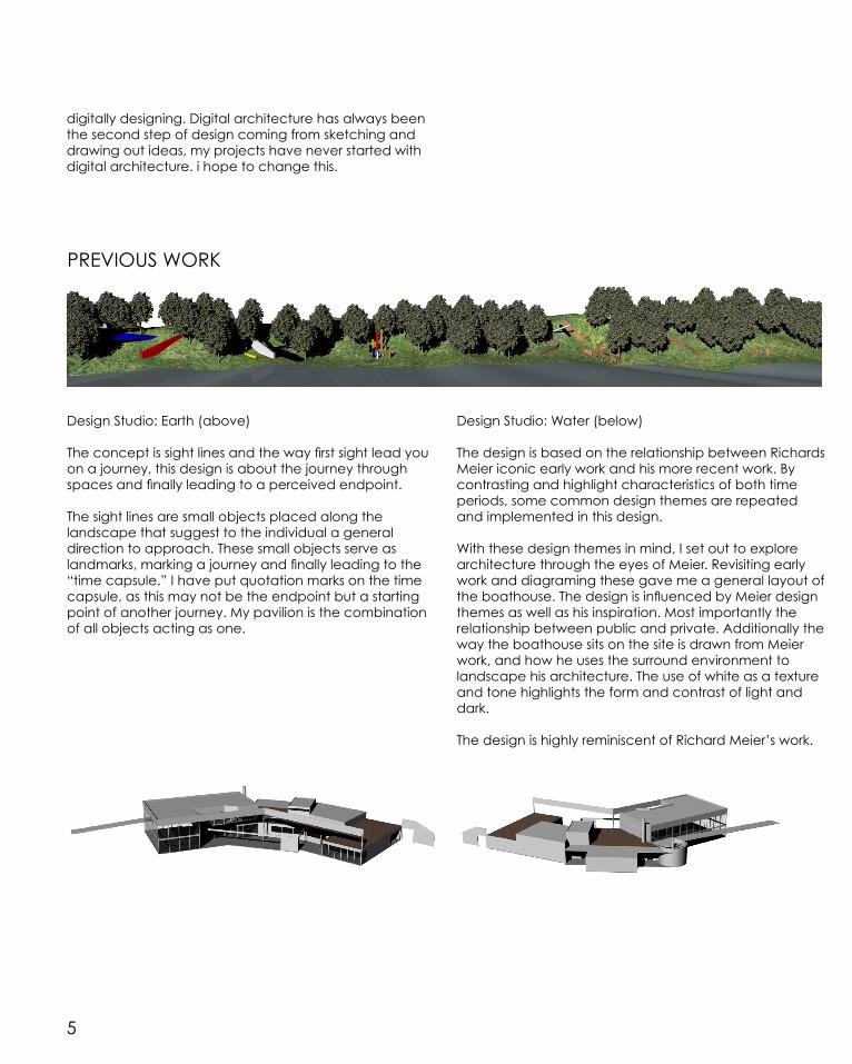
Design Studio: Earth (above)
The concept is sight lines and the way first sight lead you on a journey, this design is about the journey through spaces and finally leading to a perceived endpoint.
The sight lines are small objects placed along the landscape that suggest to the individual a general direction to approach. These small objects serve as landmarks, marking a journey and finally leading to the “time capsule.” I have put quotation marks on the time capsule, as this may not be the endpoint but a starting point of another journey. My pavilion is the combination of all objects acting as one.
digitally designing. Digital architecture has always been the second step of design coming from sketching and drawing out ideas, my projects have never started with digital architecture. i hope to change this.
Design Studio: Water (below)
The design is based on the relationship between Richards Meier iconic early work and his more recent work. By contrasting and highlight characteristics of both time periods, some common design themes are repeated and implemented in this design.
With these design themes in mind, I set out to explore architecture through the eyes of Meier. Revisiting early work and diagraming these gave me a general layout of the boathouse. The design is influenced by Meier design themes as well as his inspiration. Most importantly the relationship between public and private. Additionally the way the boathouse sits on the site is drawn from Meier work, and how he uses the surround environment to landscape his architecture. The use of white as a texture and tone highlights the form and contrast of light and dark.
The design is highly reminiscent of Richard Meier’s work.
PREVIOUS WORK

PART A.CONCEPTUALISATION
7
DESIGN FUTURING
We as a human race, as individuals are ‘awake,’ we live, breathe and do it all again the next day, and the day after that if we make it to then. We have a interval drive, we are conscious living souls living on this earth, free thinking individuals whom are curious about the world we construct and live in. Instinct human behaviour is to want to survive, however survival at the cost of the environment and the ecologies within such environments. We are living a unsustainable present, only recently we realised our immediate actions affect the future, this cause and affect model, is a spilling loop to the eventual death of our race and the planet in which we inhabit.
The future is constructed from the present, a future isn’t just handed to us, rather we earn it through sustainability, by realising that our immediate actions have a affect on the future, we rethink such actions and act accordingly. However the model which is created is a constructed future, and this begs the question should we continue on the current path where our auto-destructive nature to sustain the current and sacrifice the future, or should we aim for this ‘designed future?’
The ways in which we conduct and produce a design has more depth than some realise. A design has the ability to change the future; a good design sets the tone for all future design hence it changes the future. Once we realise this design, will be more critical, engaging in the world around us more efficiently. Architecturally speaking, one great design, has the ability to alter the course of the future. Design Futuring is a style of design
that generates a set of outcomes rather than the best. This set of outcomes is then analysed against society and the individuals living in it to eluviate the best outcome which will lead to a positive influence in the present and the future.
Challenging the ways we currently design is at the forefront of design futuring. By doing so we extend the longevity of the future. Challenging the process in which we design redirects the future on a different path. If a designed future that embraces new technologies, imagination and alters the design process as we know it, we have the moral cause to do so. Instead of living in a capsule leading to the inevitable doom of this planet of unsustained architecture and design, we should live in the present free of such things that aims for a better future beyond our horizon.
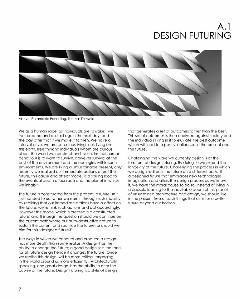
Above: Parametric Panneling, Thomas Diewald
A.1
8
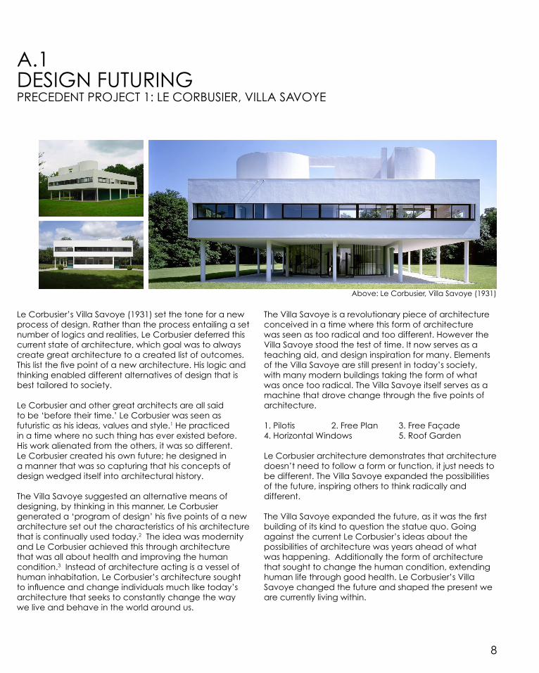
Above: Le Corbusier, Villa Savoye (1931)
DESIGN FUTURINGPRECEDENT PROJECT 1: LE CORBUSIER, VILLA SAVOYE
Le Corbusier’s Villa Savoye (1931) set the tone for a new process of design. Rather than the process entailing a set number of logics and realities, Le Corbusier deferred this current state of architecture, which goal was to always create great architecture to a created list of outcomes. This list the five point of a new architecture. His logic and thinking enabled different alternatives of design that is best tailored to society.
Le Corbusier and other great architects are all said to be ‘before their time.’ Le Corbusier was seen as futuristic as his ideas, values and style.1 He practiced in a time where no such thing has ever existed before. His work alienated from the others, it was so different. Le Corbusier created his own future; he designed in a manner that was so capturing that his concepts of design wedged itself into architectural history.
The Villa Savoye suggested an alternative means of designing, by thinking in this manner, Le Corbusier generated a ‘program of design’ his five points of a new architecture set out the characteristics of his architecture that is continually used today.2 The idea was modernity and Le Corbusier achieved this through architecture that was all about health and improving the human condition.3 Instead of architecture acting is a vessel of human inhabitation, Le Corbusier’s architecture sought to influence and change individuals much like today’s architecture that seeks to constantly change the way we live and behave in the world around us.
The Villa Savoye is a revolutionary piece of architecture conceived in a time where this form of architecture was seen as too radical and too different. However the Villa Savoye stood the test of time. It now serves as a teaching aid, and design inspiration for many. Elements of the Villa Savoye are still present in today’s society, with many modern buildings taking the form of what was once too radical. The Villa Savoye itself serves as a machine that drove change through the five points of architecture.
1. Pilotis 2. Free Plan 3. Free Façade 4. Horizontal Windows 5. Roof Garden
Le Corbusier architecture demonstrates that architecture doesn’t need to follow a form or function, it just needs to be different. The Villa Savoye expanded the possibilities of the future, inspiring others to think radically and different.
The Villa Savoye expanded the future, as it was the first building of its kind to question the statue quo. Going against the current Le Corbusier’s ideas about the possibilities of architecture was years ahead of what was happening. Additionally the form of architecture that sought to change the human condition, extending human life through good health. Le Corbusier’s Villa Savoye changed the future and shaped the present we are currently living within.
A.1

9
DESIGN FUTURINGPRECEDENT PROJECT 2: FOSTER + PARTNERS, HEARST TOWER
Above: Foster + Partners, Hearst Tower (2006)
Hearst Tower was a dream, a dream commissioned in the 1920’s as a skyscraper that was cut short due to the Great Depression. The dream lived on in the hopes that one day a skyscraper would be built upon it. Almost a decade after its completion architects of Foster + Partners accomplished the dream.5 Foster adopted this new logic of design that he used to generate forms and geometries. Through generative form finding, structural optimisation and material performance Hearst Tower reflects the best conceivable outcome that responds to the surrounding environment.
Hearst Tower and other examples of design futuring are always different from their surroundings. The architectural style itself is unique and different from the norm, however it’s not unique only for this reason. Hearst Tower is currently at the cusp of changing the future of design, young architects are being inspired by its form and design, it serves as a beacon to aim towards. Hearst Tower is currently changing the future through the way we think of design. Design is no longer constrained by the limitation of our minds. Design is being projected into the future through the use of technology, parametric modelling; testing and analysing material, geometry and the affect ambient weather condition have on the over all form. This form of modelling consisting of design designing another designs. Hearst Tower set the example that architecture can be done successfully using parametric modelling. Hearst tower is instigating change.
The design showcases sympathy to the building’s history. Fosters’ design doesn’t over shadow the existing structure, rather he amplifies it. The design manages to create a juxtaposition between the old and new yet harmonising them together in unity.6 This careful design symbolises a respect for the past, this is shown by the way Foster lightly places the new addition on the old, the weightless feeling that is portrayed through the materiality and shape positively contrast with the existing structure, increasing the effect of the overall structure.
Design Futuring core belief is to sustain the future through good design in the present. The design of Hearst Tower is the first of its kind in New York City awarded with the LEED gold certified through its environmental consideration.7 The tower was designed to sustain the future, the geometry reducing the materiality, heat conductive limestone acting as a thermal heat sinks, large glass façade to reduce the need for lighting and the circulation of water around the building to control ambient temperatures.8 All these designed characteristic sustaining the present, and unlocking brighter futures where other designs wish to reflect the same elements of environmental consideration.
For a design to change the world it must be appreciated. Given the chance, all architecture in some way or another will inspire change. However it is more important what we inspire rather than if we inspire.
A.1
“Dreams seem to be hope-hopes that we will not allow ourselves to become extinct.” 4

10
DESIGN COMPUTATION A.2
Above: Material Computation: Loop Aggregate Architectures – Project 01, ICD
Design computation has become an extension of architecture over the past half-decade, however more recently design computation has become a tool of design rather than a technique with the emergence of complex Computer Aided Design (CAD) software. The technique of Design computation is similar to the contemporary design process, however rather than the designer conceiving an idea and refining, the designer allows the software to generate forms from inputted data to conceive a concept or form.
The terms computerization and computation often get confused and mixed up with one another. Computerization within the design process is the use of computers to assist the designer in presenting an idea. This may be generating 3D renders, plans and elevations or even drafting a design. Contrastingly design computation is the use of computers in the form of algorithms and programs to generate forms and geometries to produce pieces of architecture.
With the current exponential growth of technology in society, design computation could very much be the future of design and architecture. Design computation has the power to eradicate the modern day architect, as it allows anybody to become one, which leads to the question, Is this the type of design future we want?
“CAD might conspire against creative though…. By encouraging ‘fake’ creativity”
The use of computation within the design process allows much more powerful ideas to be conveyed and created. Computation has evolved from a means of communicating ideas to a method of creating ideas. A vast majority of individuals believe that computation is ‘just a tool’ used in the creative process, however computation is no longer just a tool but rather a method of design. The design that was once lead by the designer (in this case the architect) is now given to a third party (the computer) to generate a design. Through computation what we are designing in a way seems inhuman, as to say, it was not created for humans, but rather created as model of best fit. The architect or designer has always had the final call, however the core of the design, the soul of the design is not real, it is a fake creation.
Over the past decade computation is changing the way we practice and create architecture. The use of computation allows architects to test a design before construction. The design hence is more adapted to the surround environment. The design or the concept has been tested against the existing site condition, commonly against solar patterns to define geometries, or structurally where the geometry may be restricted to minimize wasted material. Computation allows us to be more sustainable about our designed environment. Additionally computation allows individuals to be more creative, as it unlocked the capability of our imagination that couldn’t be conceived in the past.
11
Adaptive architecture is created. A new form of architecture, which is, adapted the environment which surrounds it. However the downfall of adaptive architecture is sooner or later, designs will become increasingly similar to one another.
Through the use of Computer Aided Design, the field of architecture and construction become more involved with one another. Building information modeling (BIM) is a relatively new form of computing software that allows all elements of architecture and construction to be in one form. The industry is changing, where once the architect consults individuals in the construction industry and vise versa, now the architect and construction industries are working together to form a design. This intertwining relationship between industry and architect allows more time efficient design however restricted design, as it must meet a ‘standard.’
Computation unlocks the potential of all future designs. The human mind for all its wisdom and intelligence is stupid when compared to a computer. Computation extends of bounds of architecture allowing impossible concepts to become reality as well as generating new concepts. Some individuals believe that such freedom of design is restrictive however the freedom which is allowed by computation fuels the design process. Computation allows architecture to achieve and conceive new geometries and methods of constructing such geometries.
Designing with computation as a process allows the created to better respond to the surrounding environment. Data about the site, solar pattern, weather condition can be used to generated a form, then the performance of such form can be tested against models to prove that the design will increase productivity or increase interaction between individual and the environment. The performance testing will evaluate the design against real life scenarios to see whether the design is successfully or not. Computation allows for performance-oriented design.
The nature of architecture is always changing. Now for the first time in history architecture is designed by computation for the people. Computational design allows a multitude on designs to be generated from an initial concept, however the outcome of such methods can be seen as inhuman and a ‘fake’ construction. There has always been shift of architecture in history, whether we choose adopt this new method in the design process is entirely up to the architect and the people living amongst the architecture.

12
DESIGN COMPUTATION A.2
PRECEDENT PROJECT 1: FRANK GEHRY, WALT DISNEY CONCERT HALL
Above: Frank Gehry, Walt Disney Concert Hall (2003)
Frank Gehry’s Walt Disney Concert Hall is a brilliant example of computerisation and computation within architecture. The design demonstrates that Computation can be used as a method of design and refinement.9
Computation within architecture was a fairly new concept when Gehry designed the concert hall hence he only adopted computation in the later stages of the design process. During this period of time, computation within architecture was only an abstract concept, tested a couple of times before. The concert hall utilised the processing power of computation to generate the digital model after initial conception by using computer aided three-dimensional interactive application software (CATIA.)
Frank Gehry’s Walt Disney Concert Hall is a good example of both computerisation and computation within the design process since it uses both. As mentioned above design computerisation and computation are entirely different techniques of design and the Concert Hall experiments with both. Computation allowed the engineering team to generate the unique structural elements used to the construct the form. The initial sketch was handed to the team whom first digitalised the sketch placing it within a program that generated the perfect structural frame through structural form finding. This structure physically and structurally sound, responding to both physical loads and appearance. Once the perfect structural frame was found, computerisation techniques where used to create the plans used to convey information to the
construction team.10 Computerisation has been and is currently heavily dependent upon to communicate ideas to the client or contractors, this normally in the form of CAD software. Computation on the other hand is a fairly new technology used to conceptualise a design, making it possible to construct.
The use of computation allowed the architects to test the structure before construction. A design is normally tested structurally, however with the use of computation, a third degree was reached allowing the architects to test more concepts, the most important, acoustics. This computation of acoustic allowed the geometry of the structure to be defined by it. Additionally computerisation and computation allowed the architects to conceive a design that might not have been possible without it.11 The amount of complex mathematics involved in this project would not have been analysed by a human.12 Computation extends the ability of the human mind, allowing more experimental forms to be designed and unlocked the imagination of the designer.
The Walt Disney Concert Hall proved that computation could be used within architecture successfully. Furthermore it showcase the extend in which computation can be used. In this case only used as a means to generate the structure, not the form. The architect can control the degree of computation within architecture.

13
DESIGN COMPUTATION A.2
PRECEDENT PROJECT 2: ICD-ITKE RESEARCH PAVILION 2013-14
Above: ICD-ITKE, Research Pavilion (2013-14)
The ICD Research Pavilion 2013-2014 differs dramatically from Frank Gehry’s Walt Disney Concert Hall in technique and style. Where the Concert hall used computation as a means of refinement, the Pavilion uses computational software to generate the form and also generate the method of fabrication.
The project seeks to showcase the potential of novel design, simulation and fabrication processes in architecture, and this is achieve by initial research into a precedent then through differentiated trabecular morphology the modular pavilion was generated.13
It seems as though the use of computation within the deign process, construction is being driven toward robotics and new technologies of fabrication. The two come hand in hand. Construction via robotics is a new technique only seen on small-scale projects like the Pavilion.14 However like computation, which was once only a concept, the future of construction is endless with the exponential growth of technology and technique. In the future, robots could fabricate and construct architecture. Additionally, with the use of artificial intelligence driving computation, and robotics, the future of architecture and design could solely live within realm of cyberspace. Currently computation requires the designer to firstly input the data, and then refine the generated outcomes for production, however in the near future when computing technology has surpassed the human mind, the design process may not even exist anymore. Computation is a powerful tool used to design
however at a certain point, the designed is no longer a human creation, it becomes inhuman.
The notion of performance architecture has been recently coined as a term to define architecture as good or bad depending on how it performs in testing. Rapid prototyping has become a common method of performance testing and is seen in the Pavilion. Small-scale reproductions are fabricated and tested. These reproduction in the hundreds as fabrication with 3D printing technology has become abundant. Prototyping doesn’t always need to be fabricated as real world scenarios can be tested on the computer using computation software.15 This technique used to generate a multitude of design variations from an initial seed, each new generation different from the last with better performance grades. The performance of the pavilion relies on the geometric morphology established by the computation program.
From a series of design principles and ideas, the form of the pavilion was generated and designed using computation as a design technique.


15
COMPOSITION/GENERATIONA.3
Above: Monocoque 2, Neri Oxman (2007)
Architecture is developing through the use of digital tools. The use of digital tools changes existing processes of architecture as well as introducing new methods of design. The art and process of design has remained fairly constant through time, even with the introduction of computerisation techniques (CAD and BIM) the design process was not affected, as it was only a transition from pen and paper to bits of data. Computerisation in architecture and design only increased productivity and efficiency. It is only now that we are on the cusp of the changing environments of architecture. Computation on the other hand has the ability to change the perception of architecture, the way we practice and design. Computation in the form of generation changes the art of design.
Generation in architecture changes the design process. It is not a question of if generation will affect the design process, generation will cause great changes in the way we design and think. Generation changes the way we think, the common way of design thinking must be adjusted to thinking algorithmically and parametrically. It is not a question of what I can design, but rather what can the script do and how does this limit or escalate my design. The design process is three-dimensional, with the introduction of generation a forth-dimension is added which enables us to explore and experiment with different realms of design and architecture. Generation in architecture changes everything.
The shift from composition to generation is in the process. Early adopters of this method of design are seen as pioneers of a new age of architecture whereas those still
practicing the current methods are seen as the ‘fathers of architecture.’ As one process grows the other will perish. The current method of design, the generalised ‘design process’ and composition will remain, however more focus will be placed on generative design.
As with any change, there are two contrasting opinions, the first welcoming generation as a new method of design believing it should be adopted to suit the changing social climate that surrounds it. Conflicting this belief are those that believe that allowing such method of design is immoral. Immoral in the fact that the outcome of this method is not a human production. The initial conception may be inspired by human thought, however the refinement of the idea or concept solely lies within the generative process. Even though the designer or architect will have the final say, the designer or architect is no longer the creator of a design but rather a middleman.
Generative architectures allows more people to design, this having both negative and positive outcomes. A positive is more individuals will be involved in the design process. More individuals brings more ideas and collaboration between fields. However with more people taking part in the design process, you encounter individuals who have no experience in architecture, designing structures of the future. This leading to a unsustainable designed future. To design towards the best possible constructed future, design generation should be used in proportion and design left to the individuals whom understand design futuring.

16
COMPOSITION/GENERATIONA.3
PRECEDENT PROJECT 2: ANTONI GAUDÍ, LA SAGRADA FAMILIA (1883- PRESENT)
Above: ANTONI GAUDÍ, LA SAGRADA FAMILIA (1883- PRESENT)
Antoni Guidí’s monumental cathedral La Sagrada Familima serves as a magnificent example of generation through computation. Guidí became involved in 1883; taking over the design process and applied his own logic and style of thinking.16 The design of the cathedral is possibly the earliest form of a computational approach of architecture. Guidí developed a system of proportions applied it to all dimensions and elements of the church, while this method not unique for its time, the manor in which he formed the system is distinctive.17
Similar to the modern day master architect Frank Gehry, Guidí approached his design as a crafter. Making three-dimension scale models to test both structure and geometry.18 This method of trial and error to establish a form is similar to computational generation. Computational generation as we know it is the generation of geometry through testing iterations of a design concept. Guidí didn’t have the luxury of the technology we currently use to generate, so this method of form-finding through model making was inefficient and time consuming.
Guidí also devised a system of string and weight suspension, Guidí believed in the beauty and efficiency of nature, his designed inspired by the surrounding world. Guidí approached his design in a biomimicry style, trying to reflect the natural elements of nature. Through his study of nature, Guidí was able to develop this program of logic. Geometries of the church are inspired elements of nature, columns resembling the patterns of trees,
and his hyperbolical vaults inspired by gravity. The use of hyperboloids, parabolas, helicoids and conoids was derived from the study of inverted weight on chain system of portion.19 Anything in tension when inverted will be in compression. Guidí was able to achieve breath-taking geometry in his cathedral through computational thinking and biomimicry.
Gaudi stance while designing the cathedral was part architectural and part engineering similar to a modern day architect using computation.20 Computation allows the testing of real world scenarios and the generation of form through the performance of testing. The geometries showcased in Guidí cathedral are the result of human computation and the generation of form through trial and error.
Generation in architecture is not a new concept. Even in the design process there is some sort of generation through refinement. Human computation of form generation a slow procedure, where the process and outcome is similar to computation via an algorithmic script. This process of producing iterations form a initial seed and analysing the characteristics of the generated to produce more iterations is a decent method of design. Computation of generative form via algorithmic script allows for more complex geometries to be explored and generated in a more efficient manor.

17
COMPOSITION/GENERATIONA.3
PRECEDENT PROJECT 2: IWAMOTOSCOTT, VOUSSOIR CLOUD (2008)
Above: IWAMOTOSCOTT, VOUSSOIR CLOUD (2008)
The complex forms and geometries seen in the Iwamoto Scoot, Voussoir cloud is the result of generative computation through a form-finding algorithm. The initial concepts of the design were two conflicting logics, the first having a pure compression vault and the second the use of lightweight material. Even though the design could have been possible without computation, computation allows the geometries to be optimised.21
The design draws from the work of architect Antonio Gaudí and his research on the hanging chain experiment. Where Gaudí calculated the geometries of his vault by model making and vigorous testing, The Voussoir cloud uses algorithm scripts including Delaunay tessellation and Rhinoscript to triangulate cell as a means of generation.22 Both methods of design similar however through algorithmic programs the generative computation process was shortened. Algorithms are more efficient.
Generation has its limitation. At this point of time, generation through algorithmic scripts is a fairly new method of design. Even though the final form of the design was developed using this method, much time was spent developing and defining the concept through hands-on model prototyping.23 Generative computation was only used has a method of refining and optimising the form where the initial idea and concept was conceived through model making.24 In the extent which computation is used, computation is only seen as a tool of design, that aids the designer. The problems we face
in the future is when computation is no longer a tool of design but a method of design, where computation is used to conceive and refine an concept.
The adoption of generative computation was critical in the design process. With such a complex concept to explore and test, generation allowed different iterations to be tested and analysed to find the perfect form. This form-finding program helped determine the profile of the vault and the internal geometrics that support the vault.25 The core of the design is the relationship between smaller geometries and other surrounding geometries to strategically express a compressive vault geometry.26 Algorithm script helped define the profile of the vaulted shape.
An algorithm in architectural design does not inhibit the design process, but rather it allows architecture to achieve more. Evident in Guidí’s La Sagrada Familima and The Voussoir Cloud generative computation enables designer to conceive designs that are not possible without them. The bounds of architecture can be pushed into the realm of imagination free of structural performance, as computation will solve all the problems through generation. The form/geometries may be a little different from the initial concept, however the core concept remains. Generation is just another tool in the design process.

18
CONCLUSION A.4
The ideas and concepts introduced thus far in the subject laid a solid foundation for the new ideas and concepts to come. Without such knowledge being introduced, I feel that any design that I would have produced would be inefficient to convey such powerful and interesting ideas that form the foundation of this subject. However now knowing the primary themes behind Design Studio Air, I have a fighting chance to produce a design that reflects the theory behind it.
The concept of design futuring is a tough pill to shallow. Understanding the significance of designing is key to the future. Without this knowledge of design, the present will be unsustainable. Designers needs to realised that they cause an immediate affect on society and the world around them. Design futuring’s core benefit is to design the best possible future through the generation and analysis of all possible futures and the best-designed future constructed towards through design. Designers typically approach a design without a temporal scale; this method of design is dangerous, as designers don’t understand their design will affect the future of all designs. Now understanding Design futuring, my design will attempt to achieve a sustainable future.
Design computation wasn’t a new concept to me. In the past I have experimented which such technology within the design process however not to the extent which this course requires. Design computation has always been a method of refinement, however now, design computation will form the basis of my design. Allowing technology to be a technique of design doesn’t faze me
out. I rather enjoy the idea of a computer algorithmic program generating my design, as I will always have the final say. The danger of this technique is allowing the program to run the design, as designers we must be able to control the design, even if the design takes place within a algorithmic program.
Allowing a program to design opens up design to new futures that couldn’t be reached before. The generation of composition allows more complex forms of be achieved however it could be viewed as limiting design. Such creation can be seen as inhuman in nature as the program designed the form, not a human. However in this case the designer will always have the final say and the initial idea.
Designing in this style firstly opens up new possibility of design. Secondary such a design will be sustainable and finally by undertaking this method, we are changing the idea of design, which I think is pretty awesome.
My intentions for the subject are very clear, I want to use the ideas and techniques introduced to become one with my current design process, to achieve a design that best reflects the principles and themes of the studio. The design will use design futuring as a core belief, computation as a method of design and finally composition and generation as a means of push and generate my design.

19
LEARNING OUTCOMESA.5
Learning and analysing the core theory that the subject is designed upon through precedent allowed me to explore the concepts as it applies to architecture and design. It is one thing to read about a concept, but a completely different notion when analysing it through built architecture. The precedent increased my understanding of concepts including, computation, futuring and composition and generation. This knowledge a good referencing tool for future design projects.
My perception of architecture and design is now skewed towards computation. Additionally my design process
has now evolved to include computation as a method to generate and refine a design concept. It is not that my understanding has developed but rather my understand has increased to include these new ideas. With the knowledge introduced thus far in the subject, I feel my designs in the past should be more critical. Every aspect of the design should be questioned against its affect on the future, and I should focus on extending my current temporal scales.
My design thinking and dexterity of tool has developed and will continue to develop.

20
ALGORITHMIC SKETCHES 001- OCTREE
A.6
Above: Foster + Partners, City Hall(2002)
The Octree component is used to partition three-dimensional space by subdividing space according to a set input or into eight octants. In this case the Octree component was used to approximate curvilinear geometry, by fitting boxes on the surface of geometries that lead to interesting patters on the original geometry.
The pattern could be manipulated by changing the seed values, either increasing/ decreasing the number of points generated on the surface or increasing/ decreasing the group value on the Octree component. The most successful variation is an increase of points generated and decrease in-group size, this lead to large amounts of boxes, however small in size, that resulted in a approximated surface where the original geometry could be depicted.
Points: 100 Group Size: 4 Points: 100 Group Size: 2 Points: 1000 Group Size: 4 Points: 1000 Group Size: 2
Points: 5000 Group Size: 2

21
ALGORITHMIC SKETCHES 002 - KANGAROO PHYSICS
Voussoir Cloud - Iwamoto Scott
A.6
Grid: 50/50Force: -20RestLength: 0
Grid: 50/50Force: -20RestLength: 2
Grid: 50/50Force: -20RestLength: 1
Grid: 15/15Force: -20RestLength: 0
Grid: 50/50Force: -10RestLength: 0
Grid: 50/50Force: -5RestLength: 0
Grid: 20/20Force: -20RestLength: 0
Kangaroo Physics allows the simulation, optimisation and form-finding of geometries within the grasshopper environment. Spring physics allows the creation of simple forces, the principles of Hooke’s law spring and the use of these forces to simulation material behaviour in the real world.
Through experimentation of the component linked to the Kangaroo physics component, different forms were generated, all fundamentally governed by the laws of spring physics. Changing the grid size allowed more springs to be present within the mesh, resulting in a more organic form. Meshes of smaller grids were more ‘tight’ and “in tension.” Changing the unitary force vector increases the effect of gravity on the springs, where the magnitude of the resultant force caused the spring or mesh to be stretched or compressed. Additionally increasing the rest length of the lines within the mesh allowed the mesh to ‘slack’ further.
Investigating mesh behaviour under different load through the use of Kangaroo physics allows the generation of “fabrics” like surfaces. Through suspending a mesh between columns and anchoring the naked edges allowed the simulation of the mesh under a unitary force.
REFERENCE LIST:
1. William J.R Curtis, Modern architecture since 1900 (987) (London: Phaidon Press Limited), 165.
2. William J.R Curtis, Modern architecture since 1900 (1987) (London: Phaidon Press Limited), 163.
3. John R. Gold, “A world of organized ease: the role of leisure in Le Corbusier’s La Ville Radieuse,” Leisure Studies 4, no. 1 (1985): 107.
4. Dunne, Anthony & Raby, Fiona (2013) Speculative Everything: Design Fiction, and Social Dreaming (MIT Press) pp. 1.
5. Redboxmedia.com, redbox, ‘Hearst Tower | Projects | Foster + Partners’, Fosterandpartners.com, 2000 <http://www.fosterandpartners.com/projects/hearst-tower/> [accessed 11 March 2015]
6. Megan Sveiven, Flashback: Hearst Tower / Foster and Partners (February 3, 2012) <http://www.archdaily.com/204701/flash-back-hearst-tower-foster-and-partners/> [accessed 7 March 2015].
7. Arcspace.com, Hearst Tower Norman, Foster & Partners (December 19, 2013) <http://www.arcspace.com/features/norman-foster--partners/hearst-tower/> [accessed 7 March 2015].
8. Abigail Alderman , 10 Years of Hearst Tower: Q&A with Architect Lord Norman Foster (January 15, 2015) <http://www.hearst.com/newsroom/10-years-of-hearst-tower-q-a-with-architect-lord-norman-foster> [accessed 7 March 2015].
9. Kolarevic, Branko, Architecture in the Digital Age: Design and Manufacturing (New York; London: Spon Press, 2003), pp. 3
10. Peters, Brady. (2013) ‘Computation Works: The Building of Algorithmic Thought’, Architectural Design, 83, 2, pp. 11-12
11. Yehuda E. Kalay, Architecture’s New Media: Principles, Thoeries, and Methods of Computer-Aided Design (Cambridge, Mass: MIT Press, 2004), pp. 3-4
12. Terzidis, K. Algorithmic Architecture (Burlington MA. Elsevier LTD (2006)
13. ArchDaily, ‘ICD-ITKE Research Pavilion 2013-14 / ICD-ITKE University Of Stuttgart’, 2014 <http://www.archdaily.com/522408/icd-itke-research-pavilion-2015-icd-itke-university-of-stuttgart/> [accessed 15 March 2015]
14. Dezeen.com, 2015 <http://www.dezeen.com/2014/06/26/icd-itke-pavilion-beetle-shells-university-of-stuttgart/> [accessed 15 March 2015]
15. Designboom | architecture & design magazine, ‘Interview With ICD/ITKE Team On Fiber-Woven Research Pavilion 2013-14’, 2014 <http://www.designboom.com/architecture/icd-itke-research-pavilion-2013-14-interview-08-18-2014/> [accessed 15 March 2015]
16. Ngm.nationalgeographic.com, ‘Gaudí’s Masterpiece - National Geographic Magazine’, 2015 <http://ngm.nationalgeo-graphic.com/2010/12/big-idea/gaudi-text/2> [accessed 14 March 2015]
17. Jones, Rennie, ‘AD Classics: La Sagrada Familia / Antoni Gaudi’, ArchDaily, 2013 <http://www.archdaily.com/438992/ad-clas-sics-la-sagrada-familia-antoni-gaudi/> [accessed 14 March 2015]
18. Laba, Izabella, ‘La Sagrada Familia And The Hyperbolic Paraboloid’, The Accidental Mathematician, 2009 <https://ilaba.wordpress.com/2009/06/14/la-sagrada-familia-and-the-hyperbolic-paraboloid/> [accessed 19 March 2015]
19. Sagradafamilia.cat, ‘The Sagrada Família » Architecture » Geometry’, 2015 <http://www.sagradafamilia.cat/sf-eng/docs_in-stit/arquitectura_d.php> [accessed 14 March 2015]
20. Laba, Izabella, ‘La Sagrada Familia And The Hyperbolic Paraboloid’, The Accidental Mathematician, 2009 <https://ilaba.wordpress.com/2009/06/14/la-sagrada-familia-and-the-hyperbolic-paraboloid/> [accessed 19 March 2015]
21. Architect, ‘Voussoir Cloud | Architect Magazine’, 2012 <http://www.architectmagazine.com/project-gallery/voussoir-cloud> [accessed 15 March 2015]

22. <http://www.dezeen.com/2008/08/08/voussoir-cloud-by-iwamotoscott/> [accessed 15 March 2015]
23. Iwamotoscott.com, ‘VOUSSOIR CLOUD - Iwamotoscott’, 2015 <http://www.iwamotoscott.com/VOUSSOIR-CLOUD> [accessed 15 March 2015]
24. Burohappold.com, ‘Voussoir Cloud - Burohappold Engineering’, 2011 <http://www.burohappold.com/projects/project/vous-soir-cloud-142/> [accessed 15 March 2015]Dezeen.com, 2015
25. Sciarc.edu, ‘Iwamotoscott Architecture - Exhibition’, 2015 <http://www.sciarc.edu/exhibition.php?id=1237> [accessed 15 March 2015]
26. Architizer, ‘Voussoir Cloud’, 2015 <http://architizer.com/projects/voussoir-cloud/> [accessed 15 March 2015]

PART B.CRITERIA DESIGN
25
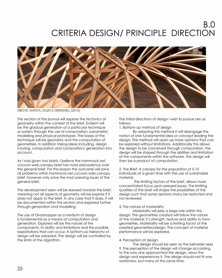
CRITERIA DESIGN/ PRINCIPLE DIRECTIONB.0
ABOVE: MATSYS, SG2012 GRIDSHELL (2012)
This section of the journal will explore the tectonics of geometry within the context of the brief. Evident will be the gradual generation of a particular technique or system through the use of computation, parametric modelling and physical prototypes. The bases of the technique will be geometry and the computation of geometries. In addition taking ideas including, design futuring, computation and composition/ generation into account.
As I was given two briefs, I believe the hammock.net.cocoon.web.canopy brief has more precedence over the general brief. For this reason the outcome will solve all problems within hammock.net.cocoon.web.canopy brief, however only solve the most pressing issues of the general brief.
The development seen will be skewed towards the brief, meaning not all aspects of geometry will be explore if it does not apply to the brief. In any case that it does, it will be documented within this section and explored further through generation and modelling.
The use of Grasshopper as a medium of design is fundamental as a means of computation and generation. Explored will be the nature of the components, its ability and limitations and the possible exploitations that can occur. A bottom-up hierarchy of design will be adopted. The design will be controlled by the limits of the algorithm.
The initial directions of design I wish to pursue are as follows:1. Bottom-up method of design By adopting this method it will disengage the notion of one fundamental idea or concept leading the design. The method will open up more opinions that can be explored without limitations. Additionally this allows the design to be conceived through computation, the design will be shaped through the abilities and limitation of the components within the software. The design will then be a product of computation. 2. The Brief: A canopy for the population of 5-10 individuals at a given time with the use of sustainable material. The limiting factors of the brief, allows more concentrated focus upon pressed issues. The limiting qualities of the brief will shape the possibilities of the design such that some opinions many be restricted and not reviewed. 3. The nature of materiality Materiality will play a large role within this design. The geometries created will follow the nature of the material; it’s strength, texture and ability to form geometries. Materiality will be a limiting factor of the created geometries/design. The concept of material performance will be explored.
4. Perception of design. The design should be seen as the beholder sees it. The perception of the design will change according to the way one approached the design, views the design and experiences it. The design should not fit one worldview, but many at the same time.

26
RESEARCH FIELD: GEOMETRY B.1
In order to showcase the design’s potential of the brief I have chosen geometry as a research field to develop a technique/ tectonic system. Out of the eight possible fields, geometry encapsulates all including material performance, patterning, biomimicry and structure. Depending on how the design is persuaded, all research fields could be researched with geometry as the fundamental concept.
Geometry is unique from the other options as geometry can be seen as an endpoint. In almost all designs, the final product is some sort of geometric form. Even when starting from something abstract like tessellation, the final would be a geometry or form taking on tessellation as technique. Geometry is a creation of design; hence any starting point will lead to geometry as the final product.
Geometry as technique is not as limiting as other research fields. Geometry is only limited in the ways you might restrict it through research. Choosing to research materiality and how the form of geometry changes according to materiality might be a limiting factor but it does not have to be one. Geometries can change and adapt to suit any situation. Geometries can evolve.
For any design to be more appealing it needs to evoke the interest of individuals viewing it. Geometry as a research field encapsulates more fields than itself. The generated result would be a combination of two or more fields, creating tension or harmony between one another. The created relationship between techniques is more capturing than just one technique. The focus of my design is a net canopy of sorts, the relationships established would be, geometry-patterning, geometry-material performance et cetera the possibly outcomes are endless. The opportunities of the design are vastly increased with geometry as a research field.
Exploring the notion of geometries and the implication that it has on the outcome is complex. When does geometry stop being geometry and starts to be something else? As considering geometry as a technique that encapsulates all, when does it stop representing a geometric form and starts to represent a tensile structure based on material performance? With the implementation of two or more research fields, the line between each begins to distort and blur. It will be difficult to organise such ideas to showcase geometry as the fundamental theme.
The concept/ notion of geometry that will be consider is:
Geometry is the relationship of shapes to itself and others that surround it to produce a form.
There are many design opportunities that can be explored through geometry. However there are many limitations. Using computation as technique allows a multitude of forms to be generated, however only a limited number of these forms can be fabricated without changing the core concept of the design. The design must therefore be skewed towards what can be fabricated and what cannot be.
Geometry in conjunction with material performance is a decent start.
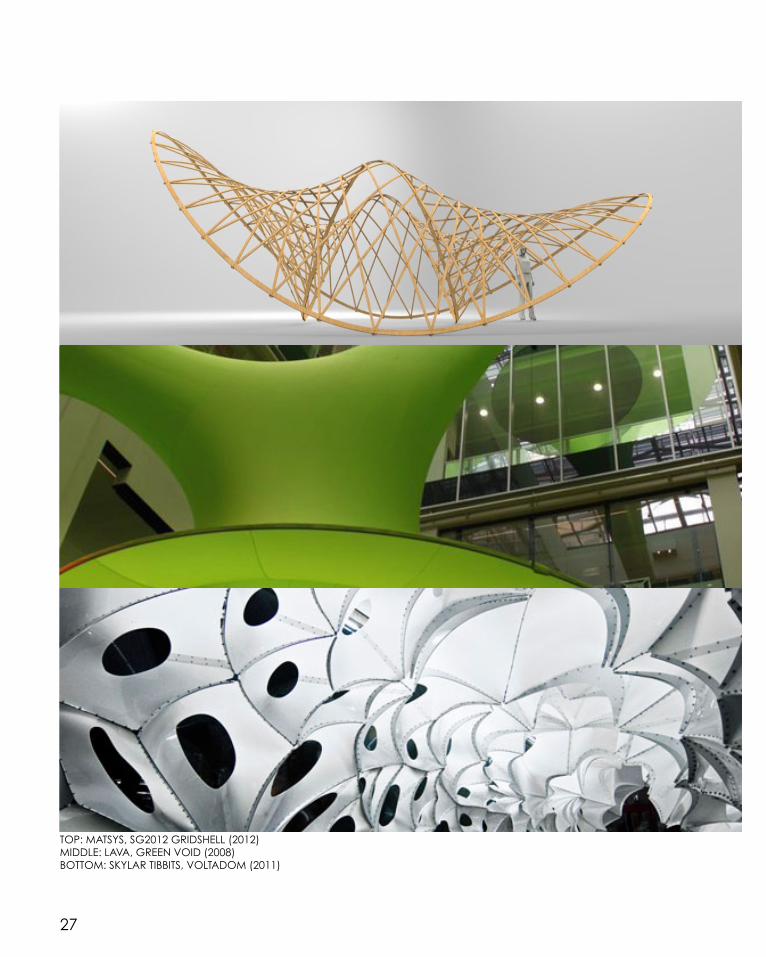
27
TOP: MATSYS, SG2012 GRIDSHELL (2012)MIDDLE: LAVA, GREEN VOID (2008)BOTTOM: SKYLAR TIBBITS, VOLTADOM (2011)

28
CASE STUDY 1.0 B.2
LAVA- GREEN VOID (2008)
Inspired by elements of the natural world, Lava’s Green Void explores geometries through tensile structures and materiality. The designed three-dimensional organic structure is a tribute to the natural phenomena in this world including spider webs, soap bubbles and plants.1
Forms of biomimicry are seen through the adaption of elements found in nature into the design typologies and structure to optimise the design.2 Computation was used to develop the form to be efficient in material as well as simulating the complexity of naturally evolving systems.
A bottom-up style of design was adopted, as the design is a result of the most efficient connection between boundaries rather than a product of human inspiration. Through the use of mathematical formula and fundamental concepts including gravity, tension and growth the design was digitally generated and fabricated.3
Materiality and the limits of such materiality are explored, as only lycra can span such distances in tension and also be sustainable.4 Additionally lycra follows the fundamental properties of gravity, tension and growth. The geometries changes with the addition of more fabric similar to a naturally evolving system, as the material grows and subject grows with it.
The driving factors of this design are:1. Nature’s efficiency in geometric 2. Materiality
This design can easily be redesign in grasshopper using meshes and kangaroo physics. By convert the meshes into springs and then anchoring naked edges and running the physics simulation, a fabric like geometry will form.
ABOVE: LAVA, GREEN VOID (2008)

29
ABOVE: LAVA, GREEN VOID (2008)

30
PARAMETRIC MANIPULATION & ITERATIVE SAMPLINGB.2
SPECIES ONE
SPECIES TWO
SPECIES THREE

31
PARAMETRIC MANIPULATION & ITERATIVE SAMPLING

32
PARAMETRIC MANIPULATION & ITERATIVE SAMPLINGB.2
SPECIES FOUR
SPECIES FIVE

33
PARAMETRIC MANIPULATION & ITERATIVE SAMPLING

34
B.2
SPECIES ONE
R:80% S:8 R:17 N:12 B:5.1 D:30 R:50% S:3 R:12 N:1.5 B:10 D:13 R:50% S:4 R:22 N:27 B:3.9 D:13.3
R:25% S:10 R:2 N:4.5 B:1.2 D:7 R:40% S:5 R:25 N:0 B:3.7 D:20.4 R:75% S:7 R:15 N:9 B:7 D:7
R: REST LENGTH S:SIDES R:THICKNESS N:NODE SIZE B:KNUCKLE SIZE D:SPACING
*

35
B.2
SPECIES TWO
R:100% P:100 C:T-F-T-T-F-F R:10% P:75 C:F-T-T-T-F-T R:85% P:50 C:T-F-T-F-F-T
R:60% P:250 C:T-F-T-F-T-F R:45% P:100 C:T-F-T-F-T-T R:25% P:25 C:T-F-F-T-T-T
R: REST LENGTH P: POINTS C:CULL
*

36
B.2
SPECIES THREE
A: CURVE A NO. POINTS B: CURVE B NO. POINTS S1:CURVE A SHIFT S2:CURVE B SHIFT
A:30 B:30 S1:0 S2:0 A:50 B:50 S1:15 S2:15 A:50 B:100 S1:20 S2:40
A:10 B:10 S1:1 S2:5 A:75 B:75 S1:15 S2:25 A:100 B:100 S1:-10 S2:-10 *
37
A:50 B:100 S1:20 S2:40
A:100 B:100 S1:-10 S2:-10
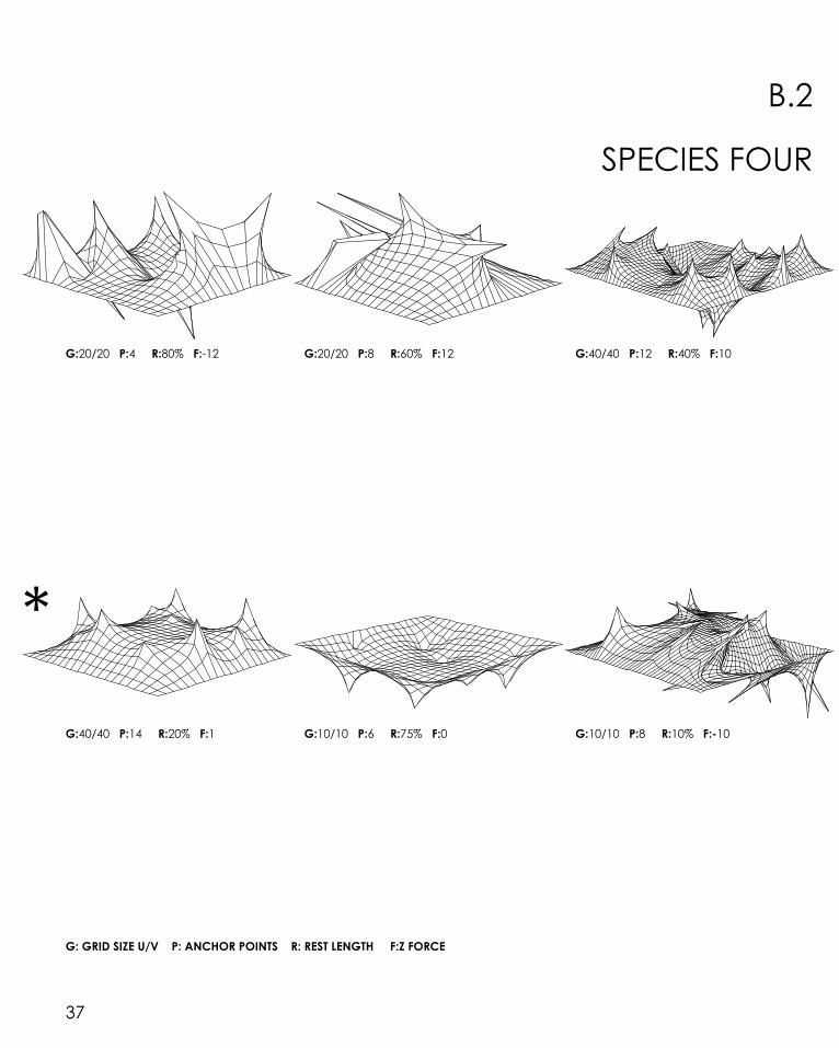
SPECIES FOUR
B.2
G: GRID SIZE U/V P: ANCHOR POINTS R: REST LENGTH F:Z FORCE
G:20/20 P:4 R:80% F:-12 G:20/20 P:8 R:60% F:12 G:40/40 P:12 R:40% F:10
G:40/40 P:14 R:20% F:1 G:10/10 P:6 R:75% F:0 G:10/10 P:8 R:10% F:-10
*

38
B.2
SPECIES FIVE
P1:POINT ONE (X,Y,Z) P2:POINT TWO (X,Y,Z) P3:POINT THREE (X,Y,Z) H: HOOPSR: REST LENGTH S:SIDES R:THICKNESS N:NODE SIZE B:KNUCKLE SIZE D:SPACING
P1:(6.9,-4.5,10) P2:(-3,-6.5,10) P3:(-3,.9,6) H:3 R:81% S:7 R:.47 N:2 B:2 D:8
P1:(5.2,3.1,2.7) P2:(1.8,5.2,-3.4) P3:(-3.8,5.3,-0.3) H:3 R:75% S:4 R:.57 N:0 B:2 D:7
P1:(-5,74) P2:(7,2,1) P3:(-1,3,8) H:4 R:50% S:9 R:.23 N:1 B:4 D:15
P1:(-2.9,-4.5,6.9) P2:(-1.9,-0.3,2.5) P3:(-5.1,2.3,-2.8) H:2 R:80% S:7 R:.10 N:0 B:0 D:3
P1:(7.2,3.7,.9) P2:(3.9,0,7.8) P3:(-1.5,-2.3,1.1) H:5 R:35% S:4 R:.25 N:1 B:1 D:3
P1:(5.4,.5,.9) P2:(3.9,-2.7,5.3) P3:(-1.5,-2.4,1) H:5 R:40% S:7 R:.0 N:1 B:3 D:0.25
*

39
P1:(5.2,3.1,2.7) P2:(1.8,5.2,-3.4) P3:(-3.8,5.3,-0.3)
P1:(7.2,3.7,.9) P2:(3.9,0,7.8) P3:(-1.5,-2.3,1.1)
OUTCOMES/CONCLUSION B.2
Selection Criteria1. Mesh/Line- fundamental to the brief and forming the basis of geometric manipulation2. Relaxation- through kangaroo physics allows depth and complex forms to be generated 3. Material- material performance is key in membrane systems, as well as introducing other themes including pattern and colour.4. Dynamic form- Geometry as technique.
LAVA’s Green Void served as a corner stone where all iterations were based off the fundamental concept of mesh relaxation, material performance of a membrane system and maximising volume whist reducing surface area.
Through five different species and six iterations of each the goal was to recreate the themes behind the Green Void and to pushing the design potential of such themes. The outcomes are dramatically different to the Green Void in aesthetics however similar in the style and themes that the design is based upon.
Through the process of generation and manipulation the designs are seen to be restricted by the themes that define it. However by layering different themes on top of one another, caused a diffusion/confusion where the fundamental theme is present, however casted by another theme. An Example of this is seen is species two, where a voronoi component was used to create the geometry, then said geometry feed into kangaroo
physics to relax the surface. Instead of the geometry defined by the anchor points as seen in the Green Void, the geometry is set by the Voronoi component then a relaxation applied to it. The process of trial and error was adopted when producing the iterations to created a sequence of geometric variations and the final version was settle upon if it was different from the Green Void, and if it clearly demonstrated a different technique.
The generated iterations could applied to architecture, however not the architecture as we have all come to know it. Rather than a building of sorts, the iterations could form the basis of a pattern or geometry. The unique qualities of the iterations is the fact that it came from a algorithmic program, meaning it can be reproduced in any manner to suit the desired outcome.
While working on the iterations two possible design process could be the final techique.1. Minial surface design/ Inflatble architecture 2. Stringing
The first design program is about defining a space, creating it out of material so it can act as a skin. The second program is about creating the illusion of a volume, by string architecture. The two programs could be seen as one system, skin and bone. These two contrasting themes can be used independently however an interesting affect would be achieved by a combination of the two.

40
CASE STUDY 2.0 B.3
Numen/For Use- TUFT Pula (2012)
ABOVE: Numen/For Use- TUFT Pula (2012)
Tuft Pula is one of many designs by Numan/For Use that is designed through experimentation. Similar to algorithms and components defining the general scale and scope of the design, materiality is a key aspect of their work. The design has no predefined function or concept, the design progresses through experimentation. This trial and error course of design is slow however the product of this design method is extremely unique and different.5
The experimentation of form and geometry is established by material performance. Numan/For Use employs adhesive tape as the primary material acting as both the framework and skin.6 A “skin and bone” system is then created; this dual function allows the framework to take on a more flexible organic form. Even though the geometry of Tuft Pula is generic and easily reproduced, the style in which they define the geometry is next to impossible to replicate as the design is produced in a trail and error. This is no defined method or procedures but rather a mentality and going wherever the design takes you.
Tuft Pula is an interactive sculpture. Individuals interact with the product. They are captured by the design as it evokes feelings within. Tuft Pula plays on the users sensational perception, simulating emotions such as tension and caution mixed with isolation and the womb affect.7 With the use of lighting and textures, these emotions are heightened. Tuft Pula is also one of the first designs by Numan/For Use to be conscious of the temporal scale.
By allowing the framework to take on a more flexible organic form, new methods of production needed to by explore. The interior is cladded in a uniform piece of tuft which was achieved by first unrolling the design onto a planar surface, then exploding said surface into small sub surfaces. Each sub surface is then individually ‘knitted’ with tuft and stitched back together again. Without this uniform tuft texture the user experience would be dramatically different. The colour, texture and form of the tuft plays a fundamental role in the design.
Even though the form was not fully realised in the early stages of the design process, the designer knew the direction in which they wanted to design towards.8 Tuft Pula plays on the principles of material performance and geometric form.

41ABOVE: Numen/For Use- TUFT Pula (2012)

42
CASE STUDY 2.0 REVERSE-ENGINEERB.3
BREP BERP EXPLODE SURFACE SURFACE MESH MESH
SLIDER
WBJOIN
1.
COMMENTARY1. Initial geometry Using a Brep allowed more freedom in geometry and minised the amount of polysurfaces generated hence the Kangaroo Physics simulation ran more smoothly.
2. MeshConverting the Brep into a mesh created lines on the surface that could be converted into springs. By adding a number slider to the V and U values, more dynamic and fluid meshes can be produced.
-Moderate to high v/u values
3. Anchor points Anchor points served as tying elements, holding the geometry in place whilst the simulation is running. By having the anchor points the naked vertices, the internal vertices were free to be effected by the simulation. Anchors points do not need to be naked vertices, however in the design of Tuft Pula, the anchor points were the naked edges.
-Naked edges and some anchor points
2.

43
WBJOIN KANGAROO PHYSICS MESH
MESH EDGES
END POINTS
SPRINGS FROM LINES
CREATE SET
VECTOR MULTIPLICATION
SLIDER
5.
4.
3.
4. Rest length multiplier Whether the ‘skin’ is in tension and the intent of this tension is set by the rest length. Lower values causing geometries to be significantly different to the original geometry being more fluid and dynamic and larger values having the opposite affect.
-Small rest length
5. Physics simulationRe-world physic simulation.
-Add in a unary force (z direction) for vault affect
Tuft Pula showcases the combination of two systems, the skin (internal surface cladding) and bone (exposed structural frame.) These two contrasting themes form a dependant relationship with one another as one cannot act without the another. This unique ‘bonding’ relationship will be explored in the species generation.
Proceeding toward time should be invested into exploring the capabilities of string design to define a geometry rather than having a volume defined by stretching a material or surface cladding.

44
TECHNIQUE: DEVELOPMENT B.4
SPECIES ONE
SPECIES TWO
SPECIES THREE
SPECIES FOUR

45

46
TECHNIQUE: DEVELOPMENT B.4
SPECIES FIVE
SPECIES SIX
SPECIES SEVEN
47

48
TECHNIQUE: DEVELOPMENT B.4
SPECIES ONE
R:40% S:8 R:7 N:9.6 B:5.6 D:13
R: REST LENGTH S:SIDES R:THICKNESS N:NODE SIZE B:KNUCKLE SIZE D:SPACING
R:50% S:3 R:6 N:17.1 B:7.5 D:8.7
R:10% S:7 R:11 N:0 B:0 D:3.9R:0% S:4 R:4 N:1.6 B:0.6 D:30
*

49
R:50% S:3 R:6 N:17.1 B:7.5 D:8.7 R:15% S:10 R:8 N:7.7 B:2.4 D:6.8
R:90% S:10 R:5 N:5.6 B:1.8 D:6.6 R:20% S:9 R:13 N:31.2 B:4.7 D:16.9

50
B.4
SPECIES TWO
R: REST LENGTH F:FORCE A: NUMBER OF ANCHOR POINTS
R:0% F:0 A:280 R:92% F:-3 A:280
R:0% F:-2 A:280 R:0% F:-2 A:24
*

51
R:92% F:-3 A:280
R:0% F:-2 A:24
B.4
R:59% F:24 A:280 R:75% F:0 A:280
R:38% F:-2 A:24 R:0% F:0 A:24
*

52
B.4
SPECIES THREE
A: CURVE A NO. POINTS B: CURVE B NO. POINTS S1:CURVE A SHIFT S2:CURVE B SHIFT F: FORCE R: REST LENGTH
A:67 B:135 S1:6 S2:3 F:-14 R:100%
A:7 B:25 S1:7 S2:2 F:8Z & 8X R:100% A:87 B:15 S1:2 S2:4 F:14 R:100%

53
B.4
A:15 B:15 S1:8 S2:2 F:20 R:100%
A:96 B:200 S1:16 S2:6 F:20Z&20X R:100%
A:44 B:136 S1:8 S2:2 F:-18 R:100%
A:155 B:200 S1:10 S2:0 F:-20Z&120X R:100%
*
54
B.4
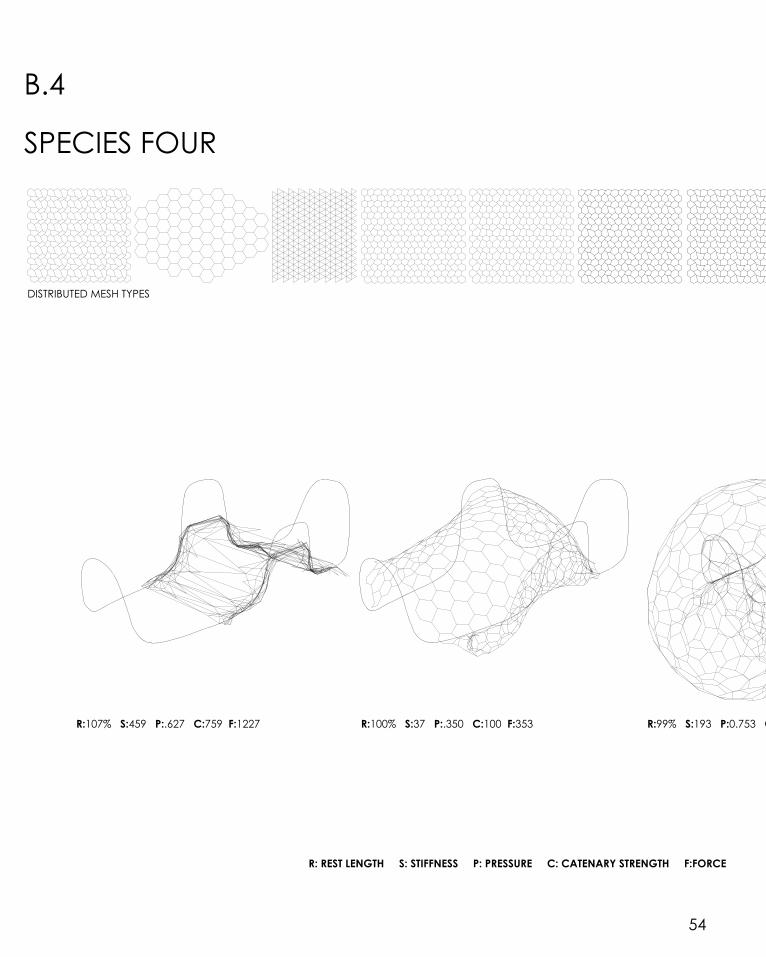
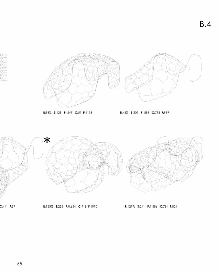
SPECIES FOUR
DISTRIBUTED MESH TYPES
R: REST LENGTH S: STIFFNESS P: PRESSURE C: CATENARY STRENGTH F:FORCE
R:99% S:193 P:0.753 C:411 F:57 R:100% S:37 P:.350 C:100 F:353 R:107% S:459 P:.627 C:759 F:1227
55
R:99% S:193 P:0.753 C:411 F:57
B.4
R:96% S:129 P:.549 C:51 F:1138 R:48% S:205 P:.893 C:785 F:989
R:155% S:255 P:0.654 C:718 F:1070 R:127% S:241 P:1.586 C:784 F:824
*

56
B.4
SPECIES FIVE
S: NUMBER OF SECTIONS A: AMPLIFICATION
S:55 A:9Z S:40 A:4.7Z
S:81 A:-4Z S:10% A:-9Z

57
S:45 A:-4Z S:85 A:6Z
S:80 A:9.1Z & -9X S:20 A:-6Z & 6.8 X
*

58
B.4
SPECIES SIX
G: GRID SIZE X: POINTS ON X AXIS Y: POINTS ON Y AXIS S: PULL STRENGTH F:FORCE
G:2 X:16 Y:.16 S:20 F:1 G:1.4 X:13 Y:.14 S:4 F:1
G:7.6 X:5 Y:.5 S:95 F:-1 G:7 X:7 Y:.7 S:46 F:-1
G:2.5 X:19 Y:.17 S:10 F:1
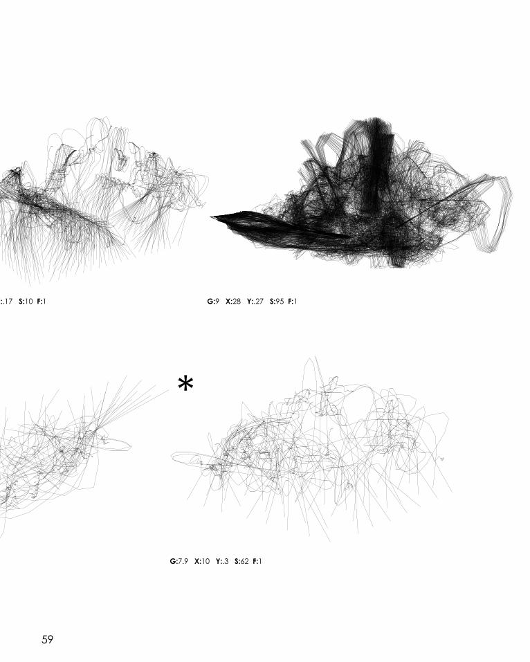
59
G:7 X:7 Y:.7 S:46 F:-1
G:2.5 X:19 Y:.17 S:10 F:1 G:9 X:28 Y:.27 S:95 F:1
G:7.9 X:10 Y:.3 S:62 F:1
*

60
B.4
SPECIES SEVEN
R: REST LENGTH F: FORCE
R:56% F:-9 R:35% F:-5
R:125% F:3
*R:100% F:0
R:75% F:2
61
R:35% F:-5 R:100% F:0 R:150% F:-7
R:75% F:2 R:45% F:0

62
B.4 OUTCOMES/CONCLUSION
Initial research and reverse engineering of Tuft Pula gave a sense of the project as a design. Defining the design limitations of the technique gave a sense of direction of the parametric manipulation and iterative sampling that would take place. Through the process of generating the iteration, the fundamental goal was the erode the design concepts of Tuft Pula, breaking down the design into it’s fundamental design principles and concepts then reengineering it into something different. This method enabled the product to be uniquely different from the initial design yet still containing the fundamental concepts it was designed upon.
Green Void by LAVA and Tuft Pula by Numen/ For use are very similar in design aesthetics, yet applying different programs of design. Green Void showcases design potential in the field of surface optimisation through stretching a material over another sub-structure, the shape defined by material performance. Whereas unlike the Green Void, Tuft Pula is not about material optimisation, but rather cladding and patterning a surface, ‘unrolling a surface’ hence the iteration explore possible cladding techniques rather than a surface optimisation techniques.
The iterations can serve as a basis of architecture and design, however some are physically impossible to reproduce in reality. The problem facing the current design process is how much of the initial idea/ concept will be changed as a result of real world restrictions. All design can be reproduced if altered from the initial concept, however is the solution anything like the initial idea?
Some of the most successful iterations have been highlighted. They are more successful as they deviate substantively from the case study however adhere to the critical design themes.
This phase of generation and iteration has been directed towards solving the problems of the brief and the set selection criteria. Even though this is limiting the possible design outcomes, the outcomes produced are more relevant in solving the design problem.
63
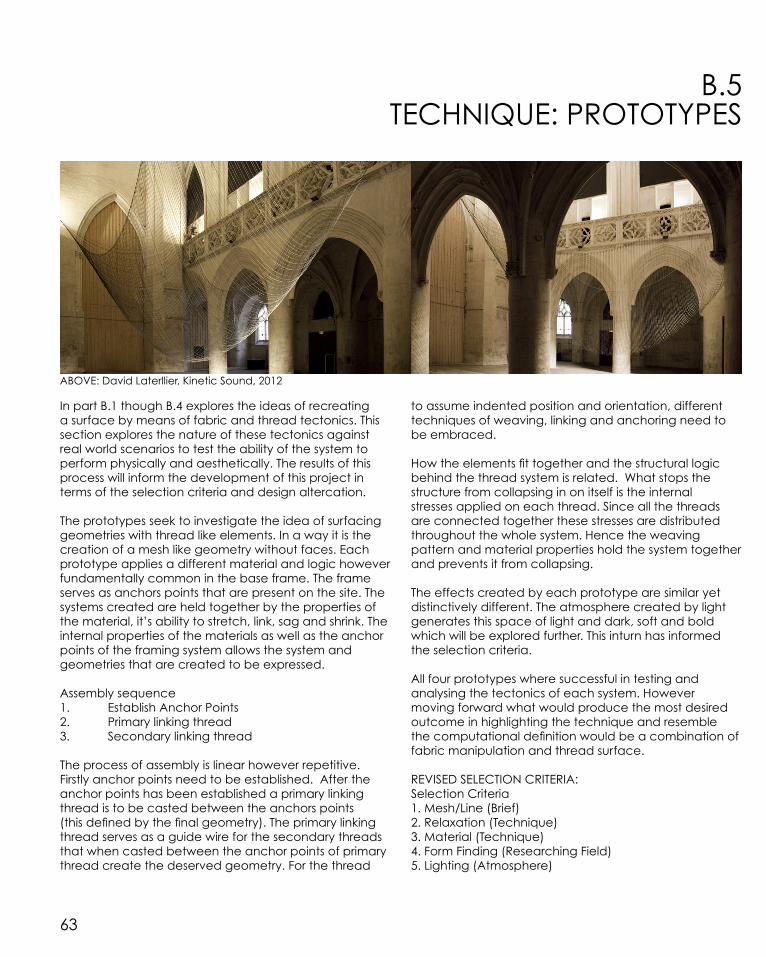
B.5 TECHNIQUE: PROTOTYPES
In part B.1 though B.4 explores the ideas of recreating a surface by means of fabric and thread tectonics. This section explores the nature of these tectonics against real world scenarios to test the ability of the system to perform physically and aesthetically. The results of this process will inform the development of this project in terms of the selection criteria and design altercation.
The prototypes seek to investigate the idea of surfacing geometries with thread like elements. In a way it is the creation of a mesh like geometry without faces. Each prototype applies a different material and logic however fundamentally common in the base frame. The frame serves as anchors points that are present on the site. The systems created are held together by the properties of the material, it’s ability to stretch, link, sag and shrink. The internal properties of the materials as well as the anchor points of the framing system allows the system and geometries that are created to be expressed.
Assembly sequence 1. Establish Anchor Points 2. Primary linking thread 3. Secondary linking thread
The process of assembly is linear however repetitive. Firstly anchor points need to be established. After the anchor points has been established a primary linking thread is to be casted between the anchors points (this defined by the final geometry). The primary linking thread serves as a guide wire for the secondary threads that when casted between the anchor points of primary thread create the deserved geometry. For the thread
to assume indented position and orientation, different techniques of weaving, linking and anchoring need to be embraced.
How the elements fit together and the structural logic behind the thread system is related. What stops the structure from collapsing in on itself is the internal stresses applied on each thread. Since all the threads are connected together these stresses are distributed throughout the whole system. Hence the weaving pattern and material properties hold the system together and prevents it from collapsing.
The effects created by each prototype are similar yet distinctively different. The atmosphere created by light generates this space of light and dark, soft and bold which will be explored further. This inturn has informed the selection criteria.
All four prototypes where successful in testing and analysing the tectonics of each system. However moving forward what would produce the most desired outcome in highlighting the technique and resemble the computational definition would be a combination of fabric manipulation and thread surface.
REVISED SELECTION CRITERIA:Selection Criteria1. Mesh/Line (Brief)2. Relaxation (Technique)3. Material (Technique)4. Form Finding (Researching Field)5. Lighting (Atmosphere)
ABOVE: David Laterllier, Kinetic Sound, 2012

64
B.5
PROTOTYPE ONE: THREAD SURFACE
Material: Thread & base frame Technique: Weaving
Outcomes: The prototype is successful in analysing material performance and its ability to produce a pattern and surface a geometry. Geometric manipulation is played upon, analysing the mesh and line technique. By shifting the anchor points 14 units counter clockwise a mesh to seen to grow out of thread. The production of a mesh like surface wraps in and on itself to produce a self-standing system. Even though the thread is strung in a linear fashion the final form is seen as curvilinear geometry.
The technique of weaving thread can provide an interesting affect of transparency and solid. Part C will explore this concept further. Additionally the atmosphere created can be heighten by the use of colour and light.

65

66

67
B.5
PROTOTYPE TWO: PUSH & PULL DUALITY
Material: Thread, rubber bands & base frame Technique: Weaving under tensionOutcomes:
Initially the prototype was supposed to be a suspended chain reproduction with thread, however it soon transformed into something quite unique. The system occurs in tension, and both components cannot exist without the other. The elastic properties of the material allow it to perform in such a way that cannot be achieved with other materials. Elastic wanting to return to its natural rest length will always be in tension hence the system created is either in tension or no force applied. The contrasting nature of each material is played upon. This idea of contrasting themes and connecting them together should be explored.

68
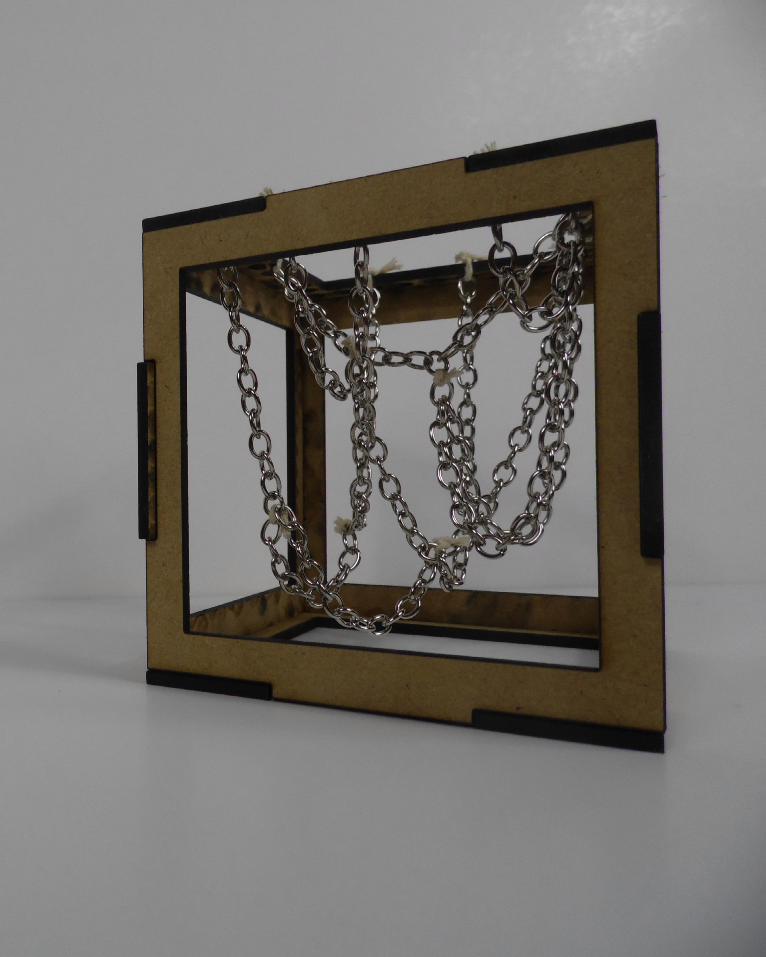
B.5
PROTOTYPE THREE: FABRIC MANIPULATION
Material: Fabric, string & base frame Technique: Surface optimisation (relaxation)Outcomes:
Surface relaxation and material performance is introduced in this prototype with the intent of changing surface geometries by external anchor points placed on the surface of the fabric. Stretching the material showcases its ability to change form and highlights the importance of anchor point positioning. Anchor point positioning determines the final form.
A cause and affect model of thinking is also introduced with each anchor point connected to other. A change in one will change another, this idea will be further researched and may be present in the final design. Additionally another aspect of this prototype, which will be researched further, is material properties and performance under a certain criteria.

69
70

71
B.5
PROTOTYPE FOUR: HANGING CHAIN
Material: Chain & base frame Technique: Alternate Hanging Chain
Outcomes: Working off an existing form-finding experiment, I wanted to alter the results by introducing additional anchor points. The sagging of the chain takes the shape of a parabola, and by changing the anchor points and the position of them, I wanted to experiment with changing the indented form. Even though the experiment is generic by changing a small constant has a greater affect on the system.
Dynamics of the system are constant and easily computed through grasshopper hence experimentation was taken to develop the technique by hanging chains off other chains. The relationships created by dependant chains produce a cohesive dependent system.
Further research and experimentation should be done in the field of twisting and inverting the system to produce alternative affects.

72
B.6 TECHNIQUE: PROPOSAL
The Brief: Hammock. Net. Cocoon. Web. CanopyRules: The Design cannot touch the groundSite: Park outside Rushall Station adjacent to Merri CreekNumber of users: 1 to 10 individuals Program: Geometric form finding though mesh relaxation.Temporal Scale: None.Material: Mixture of thread, elastic mesh material & steel framePrecedent Studies: Green Void, LAVA & Tuft Pula, Numan/ For use
Selection Criteria 1. Mesh/Line (Brief)2. Relaxation (Technique)3. Material (Technique)4. Form Finding (Researching Field)5. Lighting (Atmosphere)
The design seeks to highlight geometric form through different techniques and material systems
The geometric form of the design is not to be applied to the site but rather have the site applied to the design. The trees on site act as constants of the design and used as data to inform the final geometric form. Essentially the trees are the bounds of the design acting as anchor points for the design to hang from.
The design will use data taken from the site to first define the geometry. This geometry will then be optimised
through surface relaxation techniques; the output of the process will then be substituted for one of two surface cladding opinions, elastic mesh material, and strung thread. Additional to increase the atmosphere created by the design colour will be implemented in the surface cladding technique to produce different pockets of zones.
The two case studies and prototypes was a major factor in steering the project in its current trajectory. Currently the design is investigating two techniques, surface optimisation through geometry mesh relaxation and cladding a surface by means of threading. The first inspired by the Green Void by LAVA and the second by Numan/ For use’s Tuft Pula. Having these two contrasting themes work together to produce the same outcome has drawback on the system that will be holding the design together as each theme imposed a different technique. However this is be overcome, a major issue affecting the design at this point if external environmental factors including wind, rain and exposure to sun.
The approach is preferable over the other possible options as it implements two opposing techniques. Rather than having one fundamental technique and basing the entire project off that, having two as one will likely produce a enhanced version of each opinion.
The logic and properties of materials in an influencing factor of the design as it affects geometric form. Investigation into different material will be taken to conclude suitable material for the project.

73
B.6 TECHNIQUE: PROPOSAL
ABOVE: Site Map, Green Area Adjacent to Rushall Station
The site is situated on the northern side of Merri Creek just outside of Rushall station if on platform two. This area is uniform and not imposed by any surrounding built elements. The site provides the large open space which has been neglected by the residents of the local area. Originally a park for local residents to enjoy, now the site is a mere wasted space. Nobody uses the provided green space to sprawl out and enjoy, but rather the space which is avoided.
The site sits between a boundary that is created by the railway tracks. The tracks divides the site into two however on a larger scale connects to distant locations together. This idea of forming relationships, connection and eroding such is an interesting theme which will be used to inform the design.
The micro climate on site is constantly varying this due to the proximity to the station and near by road. Every so often ambient noise levels on site increases as trains run by causing the site to be propagated with sound. This change in condition only lasting for a split moment however constantly occurring. There is a mixture of feedback on site, from the distant noise of running water to traffic on the nearby main roads. Even though
an urban environment surrounds the site, the idea of having a natural patch of space is quite pleasant and interesting; in a way it seems to be untouched, unaffected by the outside world.
There are palm trees centred in the space that provide adequate anchoring opportunities for this given proposal. These palm trees averaging a height of 5 metres also allows the form to be ‘hovering’ over a space.
The site is a sprawled green space with minimal to no tree cover the proposal design seek to fix this problem. Other possible site issues that can be addressed by the design is the utilisation of the site, zoning of the current space into usable area and producing a space which will revitalise the site into its former purpose.
Data can be abstracted from the site and inform the design, data including heights of trees, spacing, angle in reference to one another, wavelength of ambient noise to inform curves.
The site will inform the design as much as possible.

74
B.6 TECHNIQUE: PROPOSAL
ABOVE: Proposed Elevation
ABOVE: Proposed Elevation
ABOVE: Proposed Site Plan

75
B.6 TECHNIQUE: PROPOSAL
Influencing factors of the site inspires the proposed plan. The anchor points influence the geometric form, restricting and generating form in certain areas. Techniques including surface optimisation (Green Void) and surface cladding (Tuft Pula) will be used to inform the final design. Additionally material as technique will incorporate into surfacing the form.
The technique of Green Void and Tuft Pula will be used in conjunction with one another and also methods of threading and patterning.
LEFT: Proposed Plan RIGHT: Green Void & Tuft Pula Iteration Generation

76
B.7 LEARNING OBJECTIVES AND OUTCOMES
The work produced in this module demonstrates the ability to generate a variety of design possibilities from a given situation. The areas in which this is shown is in case study 1.0 where species generation and iterations was performed, additionally in case study 2.0 with initial reverse-engineering, species generation and iteration. However I believe this is all tied in by the algorithmic sketchbook, wherein experimentation with grasshopper took place to further push the design penitential of geometry.
Moreover the prototypes showcase the ability to use grasshopper to create an initial idea seed and then prove that the concept is possible in reality through three-dimensional media. Material performance is tested, geometry created, real world forces and possible issues with fabrication and most importantly a real world scaling factor tested.
B.0 focuses on setting the design bounds of the project. Here I explore possible design outcomes and possible problems I will be facing. B.0 helped in directing the module in a certain direction rather than skipping back and forth from one concept to another. Additionally this aided in the creation of grasshopper definitions being more self-directed to the field I wanted to focus upon especially with kangaroo physics.
One of the hardest components of this module was understanding why a grasshopper component would turn red. It wasn’t a matter of finding another
component to replace the red one but understanding why the component turned red in the first place. This was done by countless hours on the grasshopper forum, reading through pages and pages of post to understand the environment and logic of grasshopper and its components.
Making a case of proposal is successfully done. It is not a matter of presenting everything, but presenting targeted ideas and concepts and showing research and understanding in these areas through experimentation and prototyping. Backing up all presented ideas with physical models or grasshopper definitions is essential and shown.
The reason why I chose geometry as a researching field is I wanted to also explore another fields at the same it. Firstly I defined what I believed to be a geometry, and then applied different researching fields to see if it matched with my definition, most of the time it did. Adopting a research field may seem restrictive as you can only explored ideas in that field, however the way in which I approached my researching field was anything but restrictive. It enabled me to explore ideas of material performance, patterning, strips and tessellation whist researching geometry as my main field.
This module as a whole including the algorithmic sketches demonstrate the ability to create, manipulate and design with grasshopper.

REFERENCE LIST:
1. L-a-v-a.net, ‘Green Void » LAVA’, 2015 <http://www.l-a-v-a.net/projects/green-void/> [accessed 26 March 2015]
2. Etherington, Rose, ‘Green Void By LAVA - Dezeen’, Dezeen, 2008 <http://www.dezeen.com/2008/12/16/green-void-by-lava/> [accessed 26 March 2015]
3. Baraona Pohl, Ethel. “Green Void / LAVA” 16 Dec 2008. ArchDaily. Accessed 26 Mar 2015. <http://www.archdaily.com/?p=10233>
4. Lomholt, I, ‘Green Void, Customs House Sydney Installation’, e-architect, 2009 <http://www.e-architect.co.uk/sydney/green-void-customs-house> [accessed 26 March 2015]
5. Irina Vinnitskaya, ‘Public Art Installations From Numen / For Use Design Collective’, ArchDaily, 2012 <http://www.archdaily.com/218341/public-art-installations-from-numen-for-use-design-collective/> [accessed 9 April 2015].
6. Numen.eu, ‘Numen / For Use » Tuft Zürich’, 2015 <http://www.numen.eu/installations/tuft/pula/> [accessed 9 April 2015].
7. designboom | architecture & design magazine, ‘Numen/For Use: Tuft Pula’, 2012 <http://www.designboom.com/design/numenfor-use-tuft-pula/> [accessed 9 April 2015].
8. Numen.eu, ‘Numen / For Use » Tuft Zürich’, 2015 <http://www.numen.eu/installations/tuft/pula/> [accessed 9 April 2015].
PART C.DETAILED DESIGN