part b - tasneef rules... · 2016-07-27 · 3 examination procedure 44 3.1 documents to be...
TRANSCRIPT

TasneefMussafah industrial area, street 14, Sector MW 4, Plot 27A, ADSB premisesAbu Dhabi United Arab Emirates Phone: +97126922333Fax: +97124454333P.O.box: [email protected]
Rules for the Classification of ShipsEffective from 1 January 2016
Part BHull and Stability


EXPLANATORY NOTE TO PART B
1. Reference editionThe reference edition for Part B is this edition effective from 1 January 2016.
2. New editions after the reference editionExcept in particular cases, a new edition of the Rules ispublished annually.
3. Effective date of the requirements3.1 All requirements in which new or amended provi-
sions with respect to those contained in the refer-ence edition have been introduced are followed by a date shown in brackets.
The date shown in brackets is the effective date of entry into force of the requirements as amended by the last updating. The effective date of all those requirements not followed by any date shown in brackets is that of the reference edition.
3.2 Item 6 below provides a summary of the technical changes from the preceding edition. In general, this list does not include those items to which only edi-torial changes have been made not affecting the effective date of the requirements contained therein.
4. Rule Variations and CorrigendaUntil the next edition of the Rules is published, Rule Variations and/or corrigenda, as necessary, will be pub-lished on the TASNEEF web site ([email protected]). Except in particular cases, paper copies of Rule Varia-tions or corrigenda are not issued.
5. Rule subdivision and cross-references5.1 Rule subdivision
The Rules are subdivided into six parts, from A to F.
Part A: Classification and Surveys
Part B: Hull and Stability
Part C: Machinery, Systems and Fire Protection
Part D: Materials and Welding
Part E: Service Notations
Part F: Additional Class Notations
Each Part consists of:• Chapters• Sections and possible Appendices• Articles• Sub-articles• Requirements
Figures (abbr. Fig) and Tables (abbr. Tab) are numbered in ascending order within each Section or Appendix.
5.2 Cross-references
Examples: Pt A, Ch 1, Sec 1, [3.2.1]or Pt A, Ch 1, App 1, [3.2.1] • Pt A means Part A
The part is indicated when it is different from the part in which the cross-reference appears. Otherwise, it is not indicated.• Ch 1 means Chapter 1
The Chapter is indicated when it is different from the chapter in which the cross-reference appears. Other-wise, it is not indicated.• Sec 1 means Section 1 (or App 1 means
Appendix 1 )
The Section (or Appendix) is indicated when it is differ-ent from the Section (or Appendix) in which the cross-reference appears. Otherwise, it is not indicated.• [3.2.1] refers to requirement 1, within sub-article 2
of article 3.
Cross-references to an entire Part or Chapter are not abbreviated as indicated in the following examples:• Part A for a cross-reference to Part A• Part A, Chapter 1 for a cross-reference to Chapter 1
of Part A.

RULES FOR THE
CLASSIFICATION OF SHIPS
Part BHull and Stability
Chapters 1 2 3 4 5 6 7 8 9 10 11 12
Chapter 1 GENERAL
Chapter 2 GENERAL ARRANGEMENT DESIGN
Chapter 3 STABILITY
Chapter 4 STRUCTURE DESIGN PRINCIPLES
Chapter 5 DESIGN LOADS
Chapter 6 HULL GIRDER STRENGTH
Chapter 7 HULL SCANTLINGS
Chapter 8 SHIPS LESS THAN 90 M IN LENGTH
Chapter 9 OTHER STRUCTURES
Chapter 10 HULL OUTFITTING
Chapter 11 CORROSION PROTECTION AND LOADING INFORMATION
Chapter 12 CONSTRUCTION AND TESTING


Tasneef Rules 2016 3
CHAPTER 1GENERAL
Section 1 Application
1 General 17
1.1 Structural requirements1.2 Limits of application to lifting appliances
2 Rule application 17
2.1 Ship parts2.2 Rules applicable to various ship parts2.3 Rules applicable to other ship items
3 Rounding off of scantlings 18
3.1
Section 2 Symbols and Definitions
1 Units 19
1.1
2 Symbols 19
2.1
3 Definitions 19
3.1 Rule length3.2 Freeboard length3.3 Ends of rule length L and midship3.4 Moulded breadth3.5 Depth3.6 Moulded draught3.7 Lightweight3.8 Deadweight3.9 Freeboard deck3.10 Superstructure3.11 Raised quarterdeck3.12 Deckhouse3.13 Trunk3.14 Standard height of superstructure3.15 Type A and Type B ships3.16 Positions 1 and 2
4 Reference co-ordinate system 21
4.1

4 Tasneef Rules 2016
Section 3 Documentation to be Submitted
1 Documentation to be submitted for all ships 22
1.1 Ships built under the Society’s supervision
2 Further documentation to be submitted for ships with certain service notations or additional class notations 22
2.1 General2.2 Service notations2.3 Additional class notations
Section 4 Calculation Programs
1 Program for the Rule based scantling 28
1.1 General1.2 LEONARDO HULL1.3 BULK
Tasneef Rules 2016 5
CHAPTER 2GENERAL ARRANGEMENT DESIGN
Section 1 Subdivision Arrangement
1 Number and arrangement of transverse watertight bulkheads 31
1.1 Number of watertight bulkheads
2 Collision bulkhead 31
2.1 Arrangement of collision bulkhead
3 After peak, machinery space bulkheads and stern tubes 32
3.1
4 Number and arrangement of tank bulkheads 32
4.1 Bulkheads in ships intended for the carriage of liquid cargoes
5 Height of transverse watertight bulkheads 32
5.1
6 Openings in watertight bulkheads and decks 32
6.1 General6.2 Openings in the watertight bulkheads below the freeboard deck6.3 Openings in the bulkheads above the freeboard deck
Section 2 Compartment Arrangement
1 Definitions 34
1.1 Cofferdam1.2 Machinery spaces of category A
2 Cofferdams 34
2.1 Cofferdam arrangement
3 Double bottoms 34
3.1 General
4 Compartments forward of the collision bulkhead 35
4.1 General
5 Minimum bow height 35
5.1 Application 5.2 General
6 Shaft tunnels 38
6.1 General
7 Watertight ventilators and trunks 38
7.1 General
8 Fuel oil tanks 38
8.1 General
6 Tasneef Rules 2016
Section 3 Access Arrangement
1 General 39
1.1
2 Double bottom 39
2.1 Inner bottom manholes2.2 Floor and girder manholes
3 Large cargo holds, large tanks and large water ballast tanks 39
3.1 General3.2 Access to tanks3.3 Access within tanks3.4 Construction of ladders
4 Shaft tunnels 40
4.1 General
5 Access to steering gear compartment 40
5.1
Tasneef Rules 2016 7
CHAPTER 3STABILITY
Section 1 General
1 General 43
1.1 Application
2 Definitions 43
2.1 General 2.2 Length of ship 2.3 Moulded breadth 2.4 Moulded depth 2.5 Timber 2.6 Timber deck cargo2.7 Timber load line
3 Examination procedure 44
3.1 Documents to be submitted3.2 Inclining test/lightweight check
Section 2 Intact Stability
1 General 46
1.1 Information for the Master1.2 Permanent ballast1.3 Still waters
2 Design criteria 46
2.1 General intact stability criteria
3 Severe wind and rolling criterion (weather criterion) 47
3.1 Scope3.2 Weather criterion
4 Effects of free surfaces of liquids in tanks 49
4.1 General4.2 Consideration of free surface effects4.3 Categories of tanks4.4 Consumable liquids4.5 Water ballast tanks4.6 Liquid transfer operations4.7 GM0 and GZ curve corrections4.8 Small tanks4.9 Remainder of liquid
5 Cargo ships carrying timber deck cargoes 50
5.1 Application5.2 Stability criteria5.3 Stability booklet5.4 Calculation of the stability curve5.5 Loading conditions to be considered

8 Tasneef Rules 2016
5.6 Assumptions for calculating loading conditions5.7 Stowage of timber deck cargoes
6 Icing 51
6.1 General6.2 Icing accumulation consequences6.3 Application6.4 Ships carrying timber deck cargoes6.5 Calculation assumptions6.6 Guidance relating to ice accretion
Appendix 1 Inclining Test and Lightweight Check
1 Inclining test and lightweight check 53
1.1 General
Appendix 2 Trim and Stability Booklet
1 Trim and stability booklet 58
1.1 Information to be included in the trim and stability booklet1.2 Loading conditions1.3 Stability curve calculation

Tasneef Rules 2016 9
CHAPTER 4STRUCTURE DESIGN PRINCIPLES
Section 1 Materials
1 General 65
1.1 Characteristics of materials1.2 Testing of materials1.3 Manufacturing processes
2 Steels for hull structure 65
2.1 Application2.2 Information to be kept on board2.3 Material factor k2.4 Grades of steel2.5 Grades of steel for structures exposed to low air temperatures2.6 Grades of steel within refrigerated spaces
3 Steels for forging and casting 70
3.1 General3.2 Steels for forging3.3 Steels for casting
4 Aluminium alloy structures 71
4.1 General4.2 Extruded plating4.3 Influence of welding on mechanical characteristics4.4 Material factor k
5 Other materials and products 71
5.1 General5.2 Iron cast parts
Section 2 Net Scantling Approach
1 Application criteria 73
1.1 General
2 Net strength characteristic calculation 73
2.1 Designer’s proposal based on gross scantlings2.2 Designer’s proposal based on net scantlings
3 Corrosion additions 75
3.1 Values of corrosion additions
10 Tasneef Rules 2016
Section 3 Strength Principles
1 General principles 76
1.1 Structural continuity1.2 Connections with higher strength steel 1.3 Connections between steel and aluminium
2 Plating 77
2.1 Insert plates and doublers
3 Ordinary stiffeners 77
3.1 General3.2 Span of ordinary stiffeners3.3 Width of attached plating3.4 Geometric properties3.5 End connections
4 Primary supporting members 80
4.1 Span of primary supporting members4.2 Width of attached plating4.3 Geometric properties4.4 Bracketed end connections4.5 Bracketless end connections4.6 Cut-outs and holes4.7 Stiffening arrangement
Section 4 Bottom Structure
1 General 84
1.1 Application1.2 General arrangement1.3 Keel1.4 Drainage and openings for air passage
2 Longitudinally framed single bottom 84
2.1 General2.2 Floors2.3 Longitudinal ordinary stiffeners
3 Transversely framed single bottom 84
3.1 General3.2 Floors
4 Longitudinally framed double bottom 85
4.1 General4.2 Double bottom height4.3 Floors4.4 Bottom and inner bottom longitudinal ordinary stiffeners4.5 Brackets to centreline girder and margin plate 4.6 Duct keel4.7 Bilge wells

Tasneef Rules 2016 11
5 Transversely framed double bottom 85
5.1 General5.2 Floors5.3 Girders5.4 Open floors
6 Bilge keel 86
6.1 Arrangement, scantlings and connections
Section 5 Side Structure
1 General 87
1.1 Application1.2 General arrangement1.3 Sheerstrake
2 Longitudinally framed single side 87
2.1 Longitudinal ordinary stiffeners2.2 Primary supporting members
3 Transversely framed single side 87
3.1 Frames3.2 Primary supporting members
4 Longitudinally framed double side 87
4.1 General4.2 Primary supporting members
5 Transversely framed double side 88
5.1 General5.2 Frames5.3 Primary supporting members
6 Frame connections 88
6.1 General6.2 Upper brackets of frames6.3 Lower brackets of frames
7 Openings in the shell plating 89
7.1 Position of openings7.2 Local strengthening
12 Tasneef Rules 2016
Section 6 Deck Structure
1 General 91
1.1 Application1.2 General arrangement1.3 Construction of watertight decks1.4 Stringer plate
2 Longitudinally framed deck 91
2.1 General2.2 Longitudinal ordinary stiffeners
3 Transversely framed deck 92
3.1 General
4 Pillars 92
4.1 General4.2 Connections
5 Hatch supporting structures 92
5.1 General
6 Openings in the strength deck 92
6.1 Position of openings and local strengthening 6.2 Corners of hatchways
7 Openings in decks other than the strength deck 94
7.1 General
Tasneef Rules 2016 13
Section 7 Bulkhead Structure
1 General 95
1.1 Application1.2 General arrangement1.3 Watertight bulkheads of trunks, tunnels, etc.1.4 Openings in watertight bulkheads1.5 Watertight doors
2 Plane bulkheads 96
2.1 General2.2 End connections of ordinary stiffeners2.3 Bracketed ordinary stiffeners
3 Corrugated bulkheads 97
3.1 General3.2 Structural arrangement3.3 Bulkhead stool
4 Non-tight bulkheads 97
4.1 Non-tight bulkheads not acting as pillars4.2 Non-tight bulkheads acting as pillars
5 Wash bulkheads 98
5.1 General5.2 Openings

Tasneef Rules 2016 15
Part BHull and Stability
Chapter 1
GENERAL
SECTION 1 APPLICATION
SECTION 2 SYMBOLS AND DEFINITIONS
SECTION 3 DOCUMENTATION TO BE SUBMITTED
SECTION 4 CALCULATION PROGRAMS

Pt B, Ch 1, Sec 1
Tasneef Rules 2016 17
SECTION 1 APPLICATION
1 General
1.1 Structural requirements
1.1.1 (1/7/2015)
Part B contains the requirements for determination of theminimum hull scantlings, applicable to all types of seagoingmonohull displacement ships of normal form, speed andproportions, made in welded steel construction, except forbulk carriers and oil tankers, for which the requirements inthe "Common Structural Rules for Bulk Carriers and OilTankers" apply. These requirements are to be integrated withthose specified in Part E, for any individual ship type, and inPart F, as applicable, depending on the additional classnotations assigned to the ships.
For ships with the notations bulk carrier ESP CSR and oiltanker ESP CSR, the above-mentioned Common StructuralRules apply as appropriate with the addition of the follow-ing requirements:
• Sec 4 - as regards the calculation programs
• Ch 3, Sec 1, Ch 3, Sec 2, Ch 3, App 1 and Ch 3, App 2- for the requirements concerning Intact Stability
• Ch 5, Sec 1, [2.1.3] - for the direct calculations of hullgirder wave induced loads in the case of ships withscantling length greater than 350 m
• Ch 5, Sec 6, [2.2] and [2.3] - for the calculation ofimpact pressures in tanks in the case of resonance
• Ch 9, Sec 7, [1.2] - for the materials of the hatch covers
• Ch 10, App 1 - for the requirements concerning rud-ders.
• Ch 11, Sec 2, [4] - for the requirements concerning theloading instruments
• Ch 12, Sec 3, [1], [2] and [3] - for the requirementsconcerning testing.
1.1.2 The requirements of Part B, Part E and Part F applyalso to those steel ships in which parts of the hull, e.g.superstructures or movable decks, are built in aluminiumalloys.
1.1.3 Ships whose hull materials are different than thosegiven in [1.1.2] and ships with novel features or unusualhull design are to be individually considered by the Society,on the basis of the principles and criteria adopted in theRules.
1.1.4 The strength of ships constructed and maintainedaccording to the Rules is sufficient for the draught corre-sponding to the assigned freeboard. The scantling draughtconsidered when applying the Rules is to be not less thanthat corresponding to the assigned freeboard.
1.1.5 Where scantlings are obtained from direct calcula-tion procedures which are different from those specified inChapter 7, adequate supporting documentation is to besubmitted to the Society, as detailed in Sec 3.
1.2 Limits of application to lifting appli-ances
1.2.1 The fixed parts of lifting appliances, considered as anintegral part of the hull, are the structures permanently con-nected by welding to the ship’s hull (for instance crane ped-estals, masts, king posts, derrick heel seatings, etc.,excluding cranes, derrick booms, ropes, rigging accessories,and, generally, any dismountable parts). The shrouds ofmasts embedded in the ship’s structure are considered asfixed parts.
1.2.2 The fixed parts of lifting appliances and their con-nections to the ship’s structure are covered by the Rules,even when the certification (especially the issuance of theCargo Gear Register) of lifting appliances is not required.
2 Rule application
2.1 Ship parts
2.1.1 GeneralFor the purpose of application of the Rules, the ship is con-sidered as divided into the following three parts:
• fore part
• central part
• aft part.
2.1.2 Fore partThe fore part includes the structures located forward of thecollision bulkhead, i.e.:
• the fore peak structures
• the stems.
In addition, it includes:
• the reinforcements of the flat bottom forward area
• the reinforcements of the bow flare area.
2.1.3 Central partThe central part includes the structures located between thecollision bulkhead and the after peak bulkhead.
Where the flat bottom forward area or the bow flare areaextend aft of the collision bulkhead, they are considered asbelonging to the fore part.
2.1.4 Aft partThe aft part includes the structures located aft of the afterpeak bulkhead.
Pt B, Ch 1, Sec 1
18 Tasneef Rules 2016
2.2 Rules applicable to various ship parts
2.2.1 The various Chapters and Sections of Part B are to beapplied for the scantling of ship parts according to Tab 1.
2.3 Rules applicable to other ship items
2.3.1 The various Chapters and Sections of Part B are to beapplied for the scantling of other ship items according toTab 2.
Table 1 : Part B Chapters and Sections applicable for the scantling of ship parts
3 Rounding off of scantlings
3.1
3.1.1 Plate thicknessesThicknesses as calculated in accordance with the rulerequirements are to be rounded off to the nearest half-milli-metre.
3.1.2 Stiffener section moduliStiffener section moduli as calculated in accordance withthe rule requirements are to be rounded off to the neareststandard value; however, no reduction may exceed 3%.
Table 2 : Part B Chapters and Sections applicablefor the scantling of other itemsPart
Applicable Chapters and Sections
General Specific
Fore part Chapter 1 Chapter 2 Chapter 3 Chapter 4 Chapter 9 (1), excluding:• Ch 9, Sec 1 • Ch 9, Sec 2 Chapter 11 Chapter 12
Ch 9, Sec 1
Central partL ≥ 90 m
Chapter 5 Chapter 6 Chapter 7
Central partL < 90 m
Chapter 8
Aft part Ch 9, Sec 2
(1) See also [2.3].
ItemApplicable Chapter
and Section
Machinery space Ch 9, Sec 3
Superstructures and deckhouses Ch 9, Sec 4
Bow doors and inner doors Ch 9, Sec 5
Side shell doors and stern doors Ch 9, Sec 6
Hatch covers Ch 9, Sec 7
Movable decks and inner ramp External ramps
Ch 9, Sec 8
Rudders Ch 10, Sec 1
Other hull outfitting Ch 10, Sec 2 Ch 10, Sec 3 Ch 10, Sec 4
Pt B, Ch 1, Sec 2
Tasneef Rules 2016 19
SECTION 2 SYMBOLS AND DEFINITIONS
1 Units
1.1
1.1.1 Unless otherwise specified, the units used in theRules are those defined in Tab 1.
2 Symbols
2.1
2.1.1
L : Rule length, in m, defined in [3.1]
L1 : L, but to be taken not greater than 200 m
L2 : L, but to be taken not greater than 120 m
LLL : Freeboard length, in m, defined in [3.2]
B : Moulded breadth, in m, defined in [3.4]
D : Depth, in m, defined in [3.5]
T : Moulded draught, in m, defined in [3.6]
Δ : Moulded displacement, in tonnes, at draught T,in sea water (density ρ = 1,025 t/m3)
CB : Total block coefficient
3 Definitions
3.1 Rule length
3.1.1 The rule length L is the distance, in m, measured onthe summer load waterline, from the forward side of thestem to the after side of the rudder post, or to the centre ofthe rudder stock where there is no rudder post. L is to be notless than 96% and need not exceed 97% of the extremelength on the summer load waterline.
3.1.2 In ships without rudder stock (e.g. ships fitted withazimuth thrusters), the rule length L is to be taken equal to97% of the extreme length on the summer load waterline.
3.1.3 In ships with unusual stem or stern arrangements, therule length L is considered on a case by case basis.
3.2 Freeboard length
3.2.1 The freeboard length LLL is the distance, in m, on thewaterline at 85% of the least moulded depth from the top ofthe keel, measured from the forward side of the stem to the
centre of the rudder stock. LLL is to be not less than 96% ofthe extreme length on the same waterline.
Table 1 : Units
3.2.2 Where the stem contour is concave above the water-line at 85% of the least moulded depth, both the forwardend of the extreme length and the forward side of the stemare to be taken at the vertical projection to that waterline ofthe aftermost point of the stem contour (above that water-line).
3.2.3 In ship design with a rake of keel, the waterline onwhich this length is measured is to be parallel to thedesigned waterline.
3.3 Ends of rule length L and midship
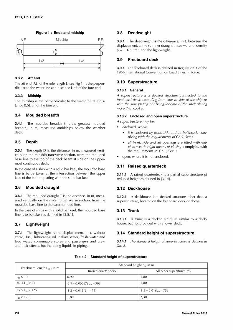
3.3.1 Fore end
The fore end (FE) of the rule length L, see Fig 1, is the per-pendicular to the summer load waterline at the forward sideof the stem.
CBΔ
1 025, LBT--------------------------=
DesignationUsual
symbolUnits
Ship’s dimensions See [2] m
Hull girder section modulus Z m3
Density ρ t/m3
Concentrated loads P kN
Linearly distributed loads q kN/m
Surface distributed loads (pressures) p kN/m2
Thicknesses t mm
Span of ordinary stiffeners and pri-mary supporting members
m
Spacing of ordinary stiffeners and primary supporting members
s m
Bending moment M kN.m
Shear force Q kN
Stresses σ, τ N/mm2
Section modulus of ordinary stiffen-ers and primary supporting mem-bers
w cm3
Sectional area of ordinary stiffeners and primary supporting members
A cm2
Pt B, Ch 1, Sec 2
20 Tasneef Rules 2016
Figure 1 : Ends and midship
3.3.2 Aft end
The aft end (AE) of the rule length L, see Fig 1, is the perpen-dicular to the waterline at a distance L aft of the fore end.
3.3.3 Midship
The midship is the perpendicular to the waterline at a dis-tance 0,5L aft of the fore end.
3.4 Moulded breadth
3.4.1 The moulded breadth B is the greatest mouldedbreadth, in m, measured amidships below the weatherdeck.
3.5 Depth
3.5.1 The depth D is the distance, in m, measured verti-cally on the midship transverse section, from the mouldedbase line to the top of the deck beam at side on the upper-most continuous deck.
In the case of a ship with a solid bar keel, the moulded baseline is to be taken at the intersection between the upperface of the bottom plating with the solid bar keel.
3.6 Moulded draught
3.6.1 The moulded draught T is the distance, in m, meas-ured vertically on the midship transverse section, from themoulded base line to the summer load line.
In the case of ships with a solid bar keel, the moulded baseline is to be taken as defined in [3.5.1].
3.7 Lightweight
3.7.1 The lightweight is the displacement, in t, withoutcargo, fuel, lubricating oil, ballast water, fresh water andfeed water, consumable stores and passengers and crewand their effects, but including liquids in piping.
3.8 Deadweight
3.8.1 The deadweight is the difference, in t, between thedisplacement, at the summer draught in sea water of densityρ = 1,025 t/m3, and the lightweight.
3.9 Freeboard deck
3.9.1 The freeboard deck is defined in Regulation 3 of the1966 International Convention on Load Lines, in force.
3.10 Superstructure
3.10.1 GeneralA superstructure is a decked structure connected to thefreeboard deck, extending from side to side of the ship orwith the side plating not being inboard of the shell platingmore than 0,04 B.
3.10.2 Enclosed and open superstructureA superstructure may be:
• enclosed, where:
• it is enclosed by front, side and aft bulkheads com-plying with the requirements of Ch 9, Sec 4
• all front, side and aft openings are fitted with effi-cient weathertight means of closing, complying withthe requirements in Ch 9, Sec 9
• open, where it is not enclosed.
3.11 Raised quarterdeck
3.11.1 A raised quarterdeck is a partial superstructure ofreduced height as defined in [3.14].
3.12 Deckhouse
3.12.1 A deckhouse is a decked structure other than asuperstructure, located on the freeboard deck or above.
3.13 Trunk
3.13.1 A trunk is a decked structure similar to a deck-house, but not provided with a lower deck.
3.14 Standard height of superstructure
3.14.1 The standard height of superstructure is defined inTab 2.
Table 2 : Standard height of superstructure
Midship F E
L/2
T
A E
LL/2
Freeboard length LLL , in mStandard height hS, in m
Raised quarter deck All other superstructures
LLL ≤ 30 0,90 1,80
30 < LLL < 75 1,80
75 ≤ LLL < 125
LLL ≥ 125 1,80 2,30
0 9, 0 00667 LLL 30–( ),+
1 2, 0 012 LLL 75–( ),+ 1 8, 0 01 LLL 75–( ),+
Pt B, Ch 1, Sec 2
Tasneef Rules 2016 21
3.15 Type A and Type B ships
3.15.1 Type A shipA Type A ship is one which:• is designed to carry only liquid cargoes in bulk;• has a high integrity of the exposed deck with only small
access openings to cargo compartments, closed bywatertight gasketed covers of steel or equivalent mate-rial; and
• has low permeability of loaded cargo compartments.A Type A ship is to be assigned a freeboard following therequirements reported in the International Load Line Con-vention 1966, as amended.
3.15.2 Type B shipAll ships which do not come within the provisions regardingType A ships stated in [3.15.1] are to be considered as TypeB ships.A Type B ship is to be assigned a freeboard following therequirements reported in the International Load Line Con-vention 1966, as amended.
3.15.3 Type B-60 shipA Type B-60 ship is any Type B ship of over 100 metres inlength which, fulfilling the requirements reported in Regula-tion 27 of Part 3, Annex I, Chapter III of the InternationalConvention on Load Lines, 1966 and Protocol of 1988, asamended, is assigned with a value of tabular freeboardwhich can be reduced up to 60 per cent of the differencebetween the “B” and “A” tabular values for the appropriateship lengths.
3.15.4 Type B-100 shipsA Type B-100 ship is any Type B ship of over 100 metres inlength which, fulfilling the requirements reported in Regula-tion 27 of Part 3, Annex I, Chapter III of the InternationalConvention on Load Lines, 1966 and Protocol of 1988, asamended, is assigned with a value of tabular freeboardwhich can be reduced up to 100 per cent of the differencebetween the “B” and “A” tabular values for the appropriateship lengths.
3.16 Positions 1 and 2
3.16.1 Position 1Position 1 includes:• exposed freeboard and raised quarter decks,• exposed superstructure decks situated forward of 0,25
LLL from the perpendicular, at the forward side of thestem, to the waterline at 85% of the least mouldeddepth measured from the top of the keel.
3.16.2 Position 2
Position 2 includes:
• exposed superstructure decks situated aft of 0,25 L fromthe perpendicular, at the forward side of the stem, to thewaterline at 85% of the least moulded depth measuredfrom the top of the keel and located at least one stand-ard height of superstructure above the freeboard deck,
• exposed superstructure decks situated forward of 0,25 Lfrom the perpendicular, at the forward side of the stem,to the waterline at 85% of the least moulded depthmeasured from the top of the keel and located at leasttwo standard heights of superstructure above the free-board deck.
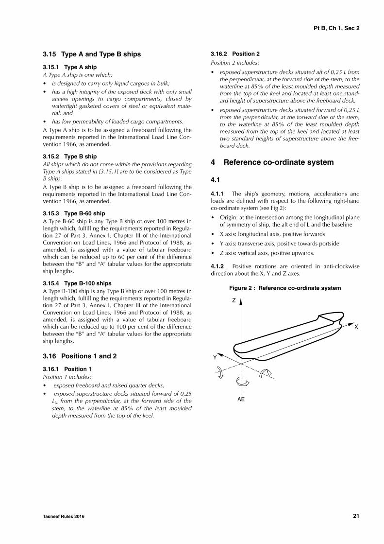
4 Reference co-ordinate system
4.1
4.1.1 The ship’s geometry, motions, accelerations andloads are defined with respect to the following right-handco-ordinate system (see Fig 2):
• Origin: at the intersection among the longitudinal planeof symmetry of ship, the aft end of L and the baseline
• X axis: longitudinal axis, positive forwards
• Y axis: transverse axis, positive towards portside
• Z axis: vertical axis, positive upwards.
4.1.2 Positive rotations are oriented in anti-clockwisedirection about the X, Y and Z axes.
Figure 2 : Reference co-ordinate system
Z
X
Y
AE

Pt B, Ch 1, Sec 3
22 Tasneef Rules 2016
SECTION 3 DOCUMENTATION TO BE SUBMITTED
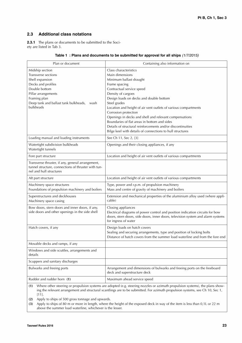
1 Documentation to be submitted for all ships
1.1 Ships built under the Society’s supervi-sion
1.1.1 Plans and documents to be submitted for approval
The plans and documents to be submitted to the Society forapproval are listed in Tab 1. This list is intended as guidancefor the complete set of information to be submitted, ratherthan an actual list of titles.
The above plans and documents are to be supplemented byfurther documentation which depends on the service nota-tion and, possibly, the additional class notation (see Pt A,Ch 1, Sec 2) assigned to the ship, as specified in [2].
Structural plans are to show details of connections of thevarious parts and, in general, are to specify the materialsused, including their manufacturing processes, welded pro-cedures and heat treatments. See also Ch 12, Sec 1, [1.6].
1.1.2 Plans and documents to be submitted for information
In addition to those in [1.1.1], the following plans and doc-uments are to be submitted to the Society for information:• general arrangement• capacity plan, indicating the volume and position of the
centre of gravity of all compartments and tanks• lines plan• hydrostatic curves• lightweight distribution• towing and mooring arrangement plan, containing the
information specified in Ch 10, Sec 4, [3.1]• list of dangerous goods intended to be carried, if any.
In addition, when direct calculation analyses are carried outby the Designer according to the rule requirements, theyare to be submitted to the Society.
1.1.3 Number of copies
The number of copies to be submitted for each plan or doc-ument is to be agreed with the Society on a case by casebasis depending on the specific conditions under whichplan approval and supervision during construction areorganised. However, it is generally equal to:
• 3 for plans and documents submitted for approval
• 2 for plans and documents submitted for information.
2 Further documentation to be submit-ted for ships with certain service notations or additional class nota-tions
2.1 General
2.1.1 Depending on the service notation and, possibly, theadditional class notation (see Pt A, Ch 1, Sec 2) assigned tothe ship, other plans or documents may be required to besubmitted to the Society, in addition to those in [1.1]. Theyare listed in [2.2] and [2.3] for the service notations andadditional class notations which require this additional doc-umentation.
However, the additional documentation relevant to a serv-ice notation or an additional class notation may be requiredalso for ships to which it is not assigned, when this isdeemed necessary by the Society on the basis, inter alia, ofthe ship service, the structural arrangements, the type ofcargo carried and its containment.
2.2 Service notations
2.2.1 The plans or documents to be submitted to the Soci-ety are listed in Tab 2.
Pt B, Ch 1, Sec 3
Tasneef Rules 2016 23
2.3 Additional class notations
2.3.1 The plans or documents to be submitted to the Soci-ety are listed in Tab 3.
Table 1 : Plans and documents to be submitted for approval for all ships (1/7/2015)
Plan or document Containing also information on
Midship sectionTransverse sectionsShell expansionDecks and profilesDouble bottomPillar arrangementsFraming planDeep tank and ballast tank bulkheads, wash bulkheads
Class characteristicsMain dimensionsMinimum ballast draughtFrame spacingContractual service speedDensity of cargoesDesign loads on decks and double bottomSteel gradesLocation and height of air vent outlets of various compartmentsCorrosion protectionOpenings in decks and shell and relevant compensationsBoundaries of flat areas in bottom and sidesDetails of structural reinforcements and/or discontinuitiesBilge keel with details of connections to hull structures
Loading manual and loading instruments See Ch 11, Sec 2, [3]
Watertight subdivision bulkheadsWatertight tunnels
Openings and their closing appliances, if any
Fore part structure Location and height of air vent outlets of various compartments
Transverse thruster, if any, general arrangement, tunnel structure, connections of thruster with tun-nel and hull structures
Aft part structure Location and height of air vent outlets of various compartments
Machinery space structuresFoundations of propulsion machinery and boilers
Type, power and r.p.m. of propulsion machineryMass and centre of gravity of machinery and boilers
Superstructures and deckhousesMachinery space casing
Extension and mechanical properties of the aluminium alloy used (where appli-cable)
Bow doors, stern doors and inner doors, if any, side doors and other openings in the side shell
Closing appliancesElectrical diagrams of power control and position indication circuits for bow doors, stern doors, side doors, inner doors, television system and alarm systems for ingress of water
Hatch covers, if any Design loads on hatch coversSealing and securing arrangements, type and position of locking boltsDistance of hatch covers from the summer load waterline and from the fore end
Movable decks and ramps, if any
Windows and side scuttles, arrangements and details
Scuppers and sanitary discharges
Bulwarks and freeing ports Arrangement and dimensions of bulwarks and freeing ports on the freeboard deck and superstructure deck
Rudder and rudder horn (1) Maximum ahead service speed
(1) Where other steering or propulsion systems are adopted (e.g. steering nozzles or azimuth propulsion systems), the plans show-ing the relevant arrangement and structural scantlings are to be submitted. For azimuth propulsion systems, see Ch 10, Sec 1, [11].
(2) Apply to ships of 500 gross tonnage and upwards.(3) Apply to ships of 80 m or more in length, where the height of the exposed deck in way of the item is less than 0,1L or 22 m
above the summer load waterline, whichever is the lesser.

Pt B, Ch 1, Sec 3
24 Tasneef Rules 2016
Sternframe or sternpost, sterntubePropeller shaft boss and brackets (1)
Derricks and cargo gearCargo lift structures
Design loads (forces and moments)Connections to the hull structures
Sea chests, stabiliser recesses, etc.
Hawse pipes
Plan of outer doors and hatchways
Plan of manholes
Plan of access to and escape from spaces
Plan of ventilation Use of spaces
Plan of tank testing Testing procedures for the various compartmentsHeight of pipes for testing
Plan of watertight doors and scheme of relevant manoeuvring devices
Manoeuvring devicesElectrical diagrams of power control and position indication circuits
Freeboard calculations
Stability documentation See Ch 3, Sec 1, [3.1]
Calculations relevant to intact stability
Equipment number calculation Geometrical elements for calculationList of equipmentConstruction and breaking load of steel wiresMaterial, construction, breaking load and relevant elongation of synthetic ropes
Helicopter deck, if any General arrangementMain structureCharacteristics of helicopters: maximum mass, distance between axles of wheels or skids, print area of wheels or skids, rotor diameter
Emergency towing arrangement See Ch 10, Sec 4, [4.3]
Windlass Design loads, scantlings and connections to the hull structures
Towing and mooring arrangements (2) Design loads, scantlings and connections to the hull structures
Ventilator pipes within forward quarter length of the ship (3)
Scantlings and connections to the hull structures
Plan or document Containing also information on
(1) Where other steering or propulsion systems are adopted (e.g. steering nozzles or azimuth propulsion systems), the plans show-ing the relevant arrangement and structural scantlings are to be submitted. For azimuth propulsion systems, see Ch 10, Sec 1, [11].
(2) Apply to ships of 500 gross tonnage and upwards.(3) Apply to ships of 80 m or more in length, where the height of the exposed deck in way of the item is less than 0,1L or 22 m
above the summer load waterline, whichever is the lesser.
Pt B, Ch 1, Sec 3
Tasneef Rules 2016 25
Table 2 : Plans and documents to be submitted depending on service notations
Service notations Plans or documents
ro-ro passenger shipro-ro cargo ship
Plans of the bow or stern ramps, elevators for cargo handling and movable decks, if any, including:• structural arrangements of ramps, elevators and movable decks with their masses• arrangements of securing and locking devices• connection of ramps, lifting and/or hoisting appliances to the hull structures, with indication of design
loads (amplitude and direction)• wire ropes and hoisting devices in working and stowed position• hydraulic jacks• loose gear (blocks, shackles, etc.) indicating the safe working loads and the testing loads• test conditionsOperating and maintenance manual (see Ch 9, Sec 5 and Ch 9, Sec 6) of bow and stern doors and rampsPlan of arrangement of motor vehicles, railway cars and/or other types of vehicles which are intended to be carriedCharacteristics of motor vehicles, railways cars and/or other types of vehicles which are intended to be carried: (as applicable) axle load, axle spacing, number of wheels per axle, wheel spacing, size of tyre printPlan of dangerous areas, in the case of ships intended for the carriage of motor vehicles with petrol in their tanks
container ship Container arrangement in holds, on decks and on hatch covers, indicating size and gross mass of containersContainer lashing arrangement indicating securing and load bearings arrangementsDrawings of load bearing structures and cell guides, indicating the design loads and including the connections to the hull structures and the associated structural reinforcements
livestock carrier Livestock arrangementDistribution of fodder and consumable liquid on the various decks and platforms
oil tanker ESPFLS tanker
Arrangement of pressure/vacuum valves in cargo tanksCargo temperatures
Tanker Cargo temperatures
chemical tanker ESP List of cargoes intended to be carried, with their densityTypes of cargo to be carried in each tankCargo temperatures Arrangement of pressure/vacuum valves in cargo tanksFor ships with independent tanks, connection of the cargo tanks to the hull structure
liquefied gas carrier Arrangement of pressure/vacuum valves in cargo tanksHeat transfer analysisDistribution of steel qualitiesFor ships with independent tanks:• cargo tank structure• connection of the cargo tanks to the hull structure• anti-floating and anti-collision arrangements
dredger Transverse sections through hoppers, wells, pump rooms and dredging machinery spacesStructural arrangement of hoppers and supporting structuresClosing arrangements, if anyConnection of dredging machinery with the hull structure
hopper dredgerhopper unit
Transverse sections through hoppers, wells, pump rooms and dredging machinery spacesStructural arrangement of hoppers and supporting structures including:• location, mass, fore and aft extent of the movable dredging equipment, for each loading condition• calculations of the horizontal forces acting on the suction pipe and on the gallowsClosing arrangements, if anyConnection of dredging machinery with the hull structure

Pt B, Ch 1, Sec 3
26 Tasneef Rules 2016
split hopper dredgersplit hopper unit
Transverse sections through hoppers, wells, pump rooms and dredging machinery spacesStructural arrangement of hoppers and supporting structures, including:• location, mass, fore and aft extent of the movable dredging equipment, for each loading condition• calculations of the horizontal forces acting on the suction pipe and on the gallowsClosing arrangements, if anyConnection of dredging machinery with the hull structureSuperstructure hinges and connections to the ship’s structure, including mass and location of the superstruc-ture centre of gravityStructure of hydraulic jack spacesDeck hinges, including location of centre of buoyancy and of centre of gravity of each half-hull, mass of equipped half-hull, half mass of spoil or water, supplies for each half-hull and mass of superstructures sup-ported by each half-hullHydraulic jacks and connections to ship’s structure including operating pressure and maximum pressure of the hydraulic jacks (cylinder and rod sides) and corresponding forcesLongitudinal chocks of bottom and deckTransverse chocksHydraulic installation of jacks, with explanatory note
tugsalvage tugtug escort
Structural arrangement of the winch and its remote control of the quick-release device for opening under loadStructural arrangement of the hook and its remote control of the quick-release device for opening under loadConnection of the towing system (winch and hook) with the hull structures
tug, salvage tug, tug escort with addi-tional service feature barge combinedbarge with additional service feature tug combined
Structural arrangement of the fore part of the tug, showing details of reinforcements in way of the connecting point Structural arrangement of the aft part of the barge, showing details of reinforcements in way of the connecting point Details of the connection system
supply vessel General plan showing the location of storage and cargo tanks with adjacent cofferdams and indicating the nature and density of cargoes intended to be carriedPlan of gas-dangerous spacesConnection of the cargo tanks with the hull structureStowage of deck cargoes and lashing arrangement with location of lashing points and indication of design loadsStructural reinforcements in way of load transmitting elements, such as winches, rollers, lifting appliances
supply vessel with additional service feature anchor han-dling or anchor han-dling stab
General arrangement of the fittings and equipment for anchor handling operationsStructural drawings of the guides/rollers used for anchor handling operationsStructural drawings of hull supporting structures in way of guides/rollers used for anchor handling operationsOnly for ships with service feature anchor handling stab: stability operational manual for anchor handling operations, as detailed in Pt E, Ch 15, Sec 2, [3.4.3]
oil recovery ship General plan showing the location of tanks intended for the retention of oily residues and systems for their treatmentPlan of the system for treatment of oily residues and specification of all relevant apparatusesSupporting structures of the system for treatment of oily residuesOperating manual
fishing vessel Minimum design temperature of refrigerated spacesStructural reinforcements in way of load transmitting elements, such as masts, gantries, trawl gallows and winches, including the maximum brake load of the winches
Service notations Plans or documents
Pt B, Ch 1, Sec 3
Tasneef Rules 2016 27
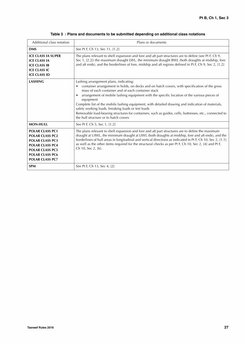
Table 3 : Plans and documents to be submitted depending on additional class notations
Additional class notation Plans or documents
DMS See Pt F, Ch 13, Sec 11, [1.2]
ICE CLASS IA SUPERICE CLASS IAICE CLASS IBICE CLASS ICICE CLASS ID
The plans relevant to shell expansion and fore and aft part structures are to define (see Pt F, Ch 9, Sec 1, [2.2]) the maximum draught LWL, the minimum draught BWL (both draughts at midship, fore and aft ends), and the borderlines of fore, midship and aft regions defined in Pt F, Ch 9, Sec 2, [1.2]
LASHING Lashing arrangement plans, indicating:• container arrangement in holds, on decks and on hatch covers, with specification of the gross
mass of each container and of each container stack• arrangement of mobile lashing equipment with the specific location of the various pieces of
equipmentComplete list of the mobile lashing equipment, with detailed drawing and indication of materials, safety working loads, breaking loads or test loadsRemovable load-bearing structures for containers, such as guides, cells, buttresses, etc., connected to the hull structure or to hatch covers
MON-HULL See Pt F, Ch 5, Sec 1, [1.2]
POLAR CLASS PC1POLAR CLASS PC2POLAR CLASS PC3POLAR CLASS PC4POLAR CLASS PC5POLAR CLASS PC6POLAR CLASS PC7
The plans relevant to shell expansion and fore and aft part structures are to define the maximum draught at UIWL, the minimum draught at LIWL (both draughts at midship, fore and aft ends), and the borderlines of hull areas in longitudinal and vertical directions as indicated in Pt F, Ch 10, Sec 2, [1.1] as well as the other items required for the structural checks as per Pt F, Ch 10, Sec 2, [4] and Pt F, Ch 10, Sec 2, [6].
SPM See Pt F, Ch 13, Sec 4, [2]

Pt B, Ch 1, Sec 4
28 Tasneef Rules 2016
SECTION 4 CALCULATION PROGRAMS
1 Program for the Rule based scant-ling
1.1 General
1.1.1 Computer programs dealing with rule checking areavailable. The Society may be contacted in order to haveinformation on these programs and associated hardwareand operating system requirements.
1.2 LEONARDO HULL
1.2.1 The LEONARDO HULL program performs the rulescantling check of plating and ordinary stiffeners at anytransverse section along the ship’s hull, primary supportingmembers and associated shell plating in various hull por-tions.
1.2.2 In particular, LEONARDO HULL makes it possibleto: • calculate the transverse section geometric properties• carry out the hull girder strength checks, including ulti-
mate strength
• carry out all the rule strength checks of:
- strakes
- longitudinal and transverse ordinary stiffeners
- strakes and ordinary stiffeners of transverse bulk-heads.
• verification and finite element analysis of hull structure,including automatic generation of part of the finite ele-ment model and load case generation. Scantling criteriaverification, in accordance with the Rules, are automati-cally performed.
1.2.3 LEONARDO HULL also calculates the steel renewalthicknesses based on rule scantlings and permits the re-assessment of ships in service.
1.3 BULK
1.3.1 The BULK program is designed to assess, accordingto the IACS Unified Requirements adopted in the Rules, thestructural strength of transverse corrugated bulkheads anddouble bottoms of new and existing bulk carriers to whichthese requirements apply.
Tasneef Rules 2016 29
Part BHull and Stability
Chapter 2
GENERAL ARRANGEMENT DESIGN
SECTION 1 SUBDIVISION ARRANGEMENT
SECTION 2 COMPARTMENT ARRANGEMENT
SECTION 3 ACCESS ARRANGEMENT

30 Tasneef Rules 2016
Symbols used in chapter 2
FPLL : “forward freeboard perpendicular”. The forwardfreeboard perpendicular is to be taken at theforward end the length LLL and is to coincidewith the foreside of the stem on the waterline onwhich the length LLL is measured.
APLL : “after freeboard perpendicular”. The afterfreeboard perpendicular is to be taken at theafter end the length LLL.

Pt B, Ch 2, Sec 1
Tasneef Rules 2016 31
SECTION 1 SUBDIVISION ARRANGEMENT
1 Number and arrangement of trans-verse watertight bulkheads
1.1 Number of watertight bulkheads
1.1.1 General
All ships, in addition to complying with the requirements of[1.1.2], are to have at least the following transverse water-tight bulkheads:
• one collision bulkhead
• one after peak bulkhead
• two bulkheads forming the boundaries of the machineryspace in ships with machinery amidships, and a bulk-head forward of the machinery space in ships withmachinery aft. In the case of ships with an electricalpropulsion plant, both the generator room and theengine room are to be enclosed by watertight bulk-heads.
1.1.2 Additional bulkheads
For ships not required to comply with subdivision regula-tions, transverse bulkheads adequately spaced and in gen-eral not less in number than indicated in Tab 1 are to befitted.
Additional bulkheads may be required for ships having tocomply with subdivision or damage stability criteria (seePart E for the different types of ships).
Table 1 : Number of bulkheads
2 Collision bulkhead
2.1 Arrangement of collision bulkhead
2.1.1 A collision bulkhead is to be fitted which is to bewatertight up to the freeboard deck. This bulkhead is to belocated at a distance from the forward perpendicular FPLLof not less than 0,05 LLL or 10 m, whichever is the less, andnot more than 0,08 or 0,05 LLL + 3 m, whichever is thegreater.
2.1.2 Where any part of the ship below the waterlineextends forward of the forward perpendicular, e.g. a bul-bous bow, the distances, in metres, stipulated in [2.1.1] areto be measured from a point either:
• at the midlength of such extension, or
• at a distance 0,015 LLL forward of the forward perpen-dicular, or
• at a distance 3 metres forward of the forward perpen-dicular; whichever gives the smallest measurement.
2.1.3 The bulkhead may have steps or recesses providedthey are within the limits prescribed in [2.1.1] or [2.1.2].
No door, manhole, ventilation duct or any other opening isto be fitted in the collision bulkhead below the freeboarddeck.
2.1.4 The Society may, on a case by case basis, accept adistance from the collision bulkhead to the forward perpen-dicular FPLL greater than the maximum specified in [2.1.1]and [2.1.2], provided that subdivision and stability calcula-tions show that, when the ship is in upright condition on fullload summer waterline, flooding of the space forward of thecollision bulkhead will not result in any part of the free-board deck becoming submerged, or in any unacceptableloss of stability.
2.1.5 Where a long forward superstructure is fitted, thecollision bulkhead is to be extended weathertight to the nextdeck above the freeboard deck. The extension need not befitted directly above the bulkhead below provided it islocated within the limits prescribed in [2.1.1] or [2.1.2] withthe exemption permitted by [2.1.6] and that the part of thedeck which forms the step is made effectively weather-tight.The extension is to be so arranged as to preclude thepossibility of the bow door causing damage to it in the caseof damage to, or detachment of, a bow door.
2.1.6 Where bow doors are fitted and a sloping loadingramp forms part of the extension of the collision bulkheadabove the freeboard deck, the part of the ramp which ismore than 2,3 m above the freeboard deck may extend for-ward of the limit specified in [2.1.1] or [2.1.2]. The ramp isto be weathertight over its complete length. Ramps not
Length (m)Number of bulkheads
for ships with aft machinery (1)
Number of bulkheads for
other ships
L < 65 3 4
65 ≤ L < 85 4 5
85 ≤ L < 105 4 5
105 ≤ L < 120 5 6
120 ≤ L < 145 6 7
145 ≤ L < 165 7 8
165 ≤ L < 190 8 9
L ≥ 190 to be defined on a case by case basis
(1) After peak bulkhead and aft machinery bulkhead are the same.

Pt B, Ch 2, Sec 1
32 Tasneef Rules 2016
meeting the above requirements are to be disregarded as anextension of the collision bulkhead.
2.1.7 The number of openings in the extension of the colli-sion bulkhead above the freeboard deck is to be restrictedto the minimum compatible with the design and normaloperation of the ship. All such openings are to be capable ofbeing closed weathertight.
3 After peak, machinery space bulk-heads and stern tubes
3.1
3.1.1 GeneralAn after peak bulkhead, and bulkheads dividing themachinery space from the cargo and passenger spaces for-ward and aft, are also to be fitted and made watertight up tothe bulkhead deck for passenger ships and to the freeboarddeck for other ships. The after peak bulkhead may, how-ever, be stepped below the bulkhead deck, provided thedegree of safety of the ship as regards subdivision is notthereby diminished.
3.1.2 Sterntubes Sterntubes are to be enclosed in a watertight space (orspaces) of moderate volume. Other measures to minimisethe danger of water penetrating into the ship in case ofdamage to sterntube arrangements may be taken at the dis-cretion of the Society.
For ships less than 65 m, where the after peak bulkhead inway of the sterntube stuffing box is not provided, sterntubesare to be enclosed in watertight spaces of moderate volume.
4 Number and arrangement of tank bulkheads
4.1 Bulkheads in ships intended for the car-riage of liquid cargoes
4.1.1 The number and location of transverse and longitu-dinal watertight bulkheads in ships intended for the carriageof liquid cargoes (tankers and similar) are to comply withthe subdivision requirements to which the ship is subject.
5 Height of transverse watertight bulk-heads
5.1
5.1.1 Transverse watertight bulkheads other than the colli-sion bulkhead and the after peak bulkhead are to extendwatertight up to the freeboard deck. In exceptional cases atthe request of the Owner, the Society may allow transversewatertight bulkheads to terminate at a deck below that fromwhich freeboard is measured, provided that this deck is atan adequate distance above the full load waterline.
5.1.2 Where it is not practicable to arrange a watertightbulkhead in one plane, a stepped bulkhead may be fitted. Inthis case, the part of the deck which forms the step is to bewatertight and equivalent in strength to the bulkhead.
6 Openings in watertight bulkheads and decks
6.1 General
6.1.1 The number of openings in watertight subdivisions isto be kept to a minimum compatible with the design andproper working of the ship. Where penetrations of water-tight bulkheads and internal decks are necessary for access,piping, ventilation, electrical cables, etc., arrangements areto be made to maintain the watertight integrity. The Societymay permit relaxation in the watertightness of openingsabove the freeboard deck, provided that it is demonstratedthat any progressive flooding can be easily controlled andthat the safety of the ship is not impaired.
6.1.2 No door, manhole ventilation duct or any otheropening is permitted in the collision bulkhead below thesubdivision deck.
6.1.3 Lead or other heat sensitive materials may not beused in systems which penetrate watertight subdivisionbulkheads, where deterioration of such systems in the eventof fire would impair the watertight integrity of the bulk-heads.
6.1.4 Valves not forming part of a piping system are notpermitted in watertight subdivision bulkheads.
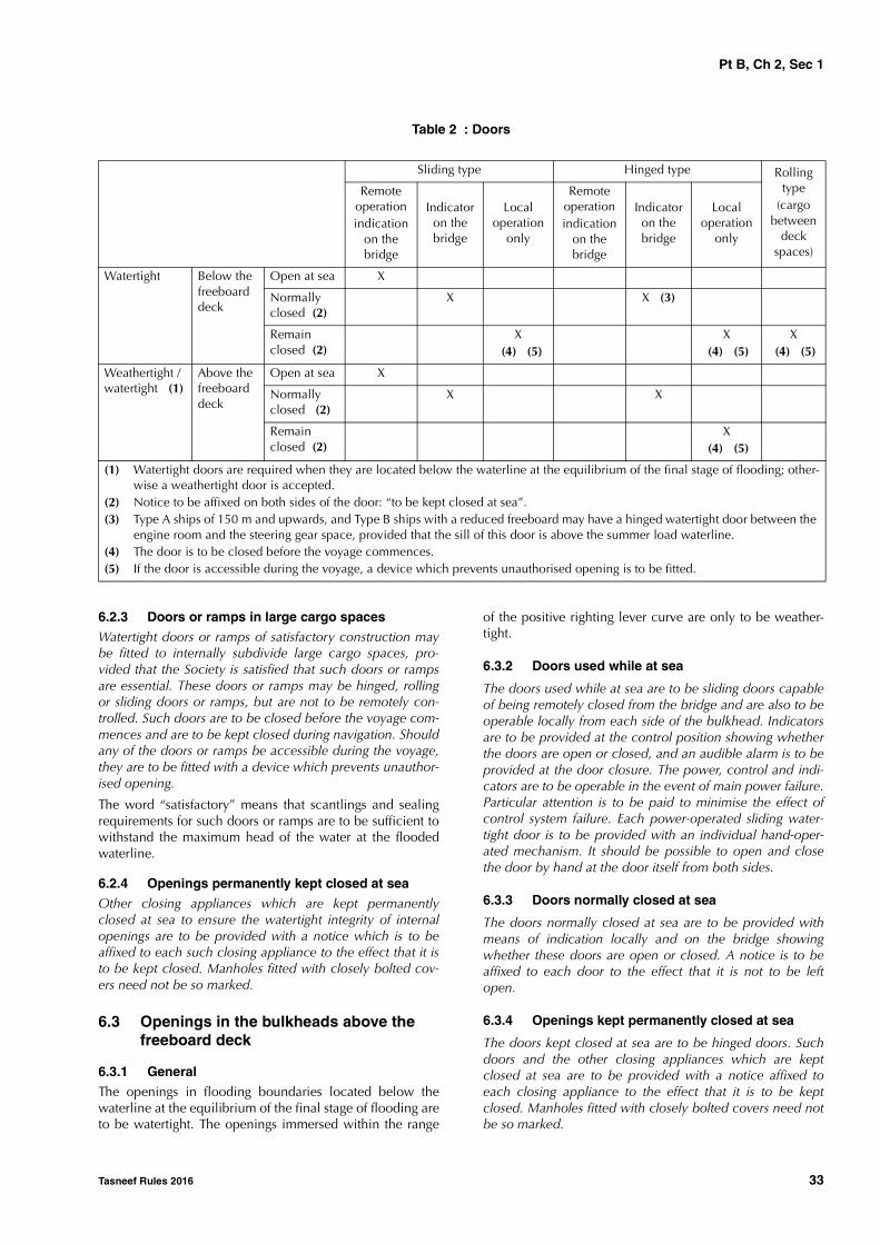
6.1.5 The requirements relevant to the degree of tightness,as well as the operating systems, for doors or other closingappliances complying with the provisions in [6.2] and [6.3]are specified in Tab 2.
6.2 Openings in the watertight bulkheads below the freeboard deck
6.2.1 Openings used while at sea
Doors provided to ensure the watertight integrity of internalopenings which are used while at sea are to be slidingwatertight doors capable of being remotely closed from thebridge and are also to be operable locally from each side ofthe bulkhead. Indicators are to be provided at the controlposition showing whether the doors are open or closed, andan audible alarm is to be provided at the door closure. Thepower, control and indicators are to be operable in theevent of main power failure. Particular attention is to bepaid to minimise the effect of control system failure. Eachpower-operated sliding watertight door is to be providedwith an individual hand-operated mechanism. The possibil-ity of opening and closing the door by hand at the dooritself from both sides is to be assured.
6.2.2 Openings normally closed at sea
Access doors and access hatch covers normally closed atsea, intended to ensure the watertight integrity of internalopenings, are to be provided with means of indicationlocally and on the bridge showing whether these doors orhatch covers are open or closed. A notice is to be affixed toeach such door or hatch cover to the effect that it is not tobe left open. The use of such doors and hatch covers is tobe authorised by the officer of the watch.
Pt B, Ch 2, Sec 1
Tasneef Rules 2016 33
Table 2 : Doors
6.2.3 Doors or ramps in large cargo spaces
Watertight doors or ramps of satisfactory construction maybe fitted to internally subdivide large cargo spaces, pro-vided that the Society is satisfied that such doors or rampsare essential. These doors or ramps may be hinged, rollingor sliding doors or ramps, but are not to be remotely con-trolled. Such doors are to be closed before the voyage com-mences and are to be kept closed during navigation. Shouldany of the doors or ramps be accessible during the voyage,they are to be fitted with a device which prevents unauthor-ised opening.
The word “satisfactory” means that scantlings and sealingrequirements for such doors or ramps are to be sufficient towithstand the maximum head of the water at the floodedwaterline.
6.2.4 Openings permanently kept closed at sea
Other closing appliances which are kept permanentlyclosed at sea to ensure the watertight integrity of internalopenings are to be provided with a notice which is to beaffixed to each such closing appliance to the effect that it isto be kept closed. Manholes fitted with closely bolted cov-ers need not be so marked.
6.3 Openings in the bulkheads above the freeboard deck
6.3.1 General
The openings in flooding boundaries located below thewaterline at the equilibrium of the final stage of flooding areto be watertight. The openings immersed within the range
of the positive righting lever curve are only to be weather-tight.
6.3.2 Doors used while at sea
The doors used while at sea are to be sliding doors capableof being remotely closed from the bridge and are also to beoperable locally from each side of the bulkhead. Indicatorsare to be provided at the control position showing whetherthe doors are open or closed, and an audible alarm is to beprovided at the door closure. The power, control and indi-cators are to be operable in the event of main power failure.Particular attention is to be paid to minimise the effect ofcontrol system failure. Each power-operated sliding water-tight door is to be provided with an individual hand-oper-ated mechanism. It should be possible to open and closethe door by hand at the door itself from both sides.
6.3.3 Doors normally closed at sea
The doors normally closed at sea are to be provided withmeans of indication locally and on the bridge showingwhether these doors are open or closed. A notice is to beaffixed to each door to the effect that it is not to be leftopen.
6.3.4 Openings kept permanently closed at sea
The doors kept closed at sea are to be hinged doors. Suchdoors and the other closing appliances which are keptclosed at sea are to be provided with a notice affixed toeach closing appliance to the effect that it is to be keptclosed. Manholes fitted with closely bolted covers need notbe so marked.
Sliding type Hinged type Rolling type
(cargo between
deck spaces)
Remote operationindication
on the bridge
Indicator on the bridge
Local operation
only
Remote operationindication
on the bridge
Indicator on the bridge
Local operation
only
Watertight Below the freeboard deck
Open at sea X
Normally closed (2)
X X (3)
Remain closed (2)
X (4) (5)
X (4) (5)
X (4) (5)
Weathertight / watertight (1)
Above the freeboard deck
Open at sea X
Normally closed (2)
X X
Remain closed (2)
X (4) (5)
(1) Watertight doors are required when they are located below the waterline at the equilibrium of the final stage of flooding; other-wise a weathertight door is accepted.
(2) Notice to be affixed on both sides of the door: “to be kept closed at sea”.(3) Type A ships of 150 m and upwards, and Type B ships with a reduced freeboard may have a hinged watertight door between the
engine room and the steering gear space, provided that the sill of this door is above the summer load waterline.(4) The door is to be closed before the voyage commences.(5) If the door is accessible during the voyage, a device which prevents unauthorised opening is to be fitted.
Pt B, Ch 2, Sec 2
34 Tasneef Rules 2016
SECTION 2 COMPARTMENT ARRANGEMENT
1 Definitions
1.1 Cofferdam
1.1.1 A cofferdam means an empty space arranged so thatcompartments on each side have no common boundary; acofferdam may be located vertically or horizontally. As arule, a cofferdam is to be properly ventilated and of suffi-cient size to allow for inspection.
1.2 Machinery spaces of category A
1.2.1 Machinery spaces of category A are those spaces ortrunks to such spaces which contain:
• internal combustion machinery used for main propul-sion; or
• internal combustion machinery used for purposes otherthan propulsion where such machinery has in the aggre-gate a total power output of not less than 375 kW; or
• any oil fired boiler or fuel oil unit.
2 Cofferdams
2.1 Cofferdam arrangement
2.1.1 Cofferdams are to be provided between compart-ments intended for liquid hydrocarbons (fuel oil, lubricatingoil) and those intended for fresh water (drinking water,water for propelling machinery and boilers) as well as tanksintended for the carriage of liquid foam for fire extinguish-ing.
2.1.2 Cofferdams separating fuel oil tanks from lubricatingoil tanks and the latter from those intended for the carriageof liquid foam for fire extinguishing or fresh water or boilerfeed water may not be required when deemed impractica-ble or unreasonable by the Society in relation to the charac-teristics and dimensions of the spaces containing suchtanks, provided that:
• the thickness of common boundary plates of adjacenttanks is increased, with respect to the thicknessobtained according to Ch 7, Sec 1, by 2 mm in the caseof tanks carrying fresh water or boiler feed water, and by1 mm in all other cases
• the sum of the throats of the weld fillets at the edges ofthese plates is not less than the thickness of the platesthemselves
• the structural test is carried out with a head increased by1 m with respect to Ch 12, Sec 3, [2].
2.1.3 Spaces intended for the carriage of flammable liq-uids are to be separated from accommodation and service
spaces by means of a cofferdam. Where accommodationand service spaces are arranged immediately above suchspaces, the cofferdam may be omitted only where the deckis not provided with access openings and is coated with alayer of material recognized as suitable by the Society.
The cofferdam may also be omitted where such spaces areadjacent to a passageway, subject to the conditions stated in[2.1.2] for fuel oil or lubricating oil tanks.
2.1.4 Cofferdams are only required between fuel oil dou-ble bottoms and tanks immediately above where the innerbottom plating is subjected to the head of fuel oil containedtherein, as in the case of a double bottom with its top raisedat the sides.
Where a corner to corner situation occurs, tanks are not beconsidered to be adjacent.
Adjacent tanks not separated by cofferdams are to haveadequate dimensions to ensure easy inspection.
3 Double bottoms
3.1 General
3.1.1 Double bottom
a) A double bottom shall be fitted extending from the colli-sion bulkhead to the afterpeak bulkhead, as far as this ispracticable and compatible with the design and properworking of the ship.
b) Where a double bottom is required to be fitted the innerbottom shall be continued out to the ship's sides in sucha manner as to protect the bottom to the turn of thebilge. Such protection will be deemed satisfactory if theinner bottom is not lower at any part than a plane paral-lel with the keel line and which is located not less than avertical distance h measured from the keel line, as cal-culated by the formula:
h = B / 20
However, in no case is the value of h to be less than 760mm, and need not be taken as more than 2,000 mm.
c) Small wells constructed in the double bottom in connec-tion with drainage arrangements of holds, etc., shall notextend downward more than necessary. A well extend-ing to the outer bottom is, however, permitted at theafter end of the shaft tunnel. Other wells (e.g., for lubri-cating oil under main engines) may be permitted by theSociety if satisfied that the arrangements give protectionequivalent to that afforded by a double bottom comply-ing with this regulation. In no case shall the vertical dis-tance from the bottom of such a well to a planecoinciding with the keel line be less than 500 mm.

Pt B, Ch 2, Sec 2
Tasneef Rules 2016 35
d) A double bottom need not be fitted in way of watertighttanks, including dry tanks of moderate size, providedthe safety of the ship is not impaired in the event of bot-tom or side damage.
e) In the case of passenger ships to which the provisions ofregulation 1.5 apply and which are engaged on regularservice within the limits of a short international voyageas defined in regulation III/3.22, the Administration maypermit a double bottom to be dispensed with if satisfiedthat the fitting of a double bottom in that part would notbe compatible with the design and proper working ofthe ship.
f) Any part of a passenger ship or a cargo ship that is notfitted with a double bottom in accordance with para-graphs a), d) or e) shall be capable of withstanding bot-tom damages, as specified in paragraph h), in that partof the ship.
g) In the case of unusual bottom arrangements in a passen-ger ship or a cargo ship, it shall be demonstrated thatthe ship is capable of withstanding bottom damages asspecified in paragraph h).
h) Compliance with paragraphs f) or g) is to be achievedby demonstrating that si, when calculated in accord-ance with Reg. II-1 of SOLAS Convention, is not lessthan 1 for all service conditions when subject to a bot-tom damage assumed at any position along the ship'sbottom and with an extent specified in item 2) below forthe affected part of the ship:
1) Flooding of such spaces shall not render emergencypower and lighting, internal communication, signalsor other emergency devices inoperable in otherparts of the ship.
2) Assumed extent of damage shall be as follows Tab 1.
3) If any damage of a lesser extent than the maximumdamage specified in item 2) would result in a moresevere condition, such damage should be consid-ered.
i) In case of large lower holds in passenger ships, theAdministration may require an increased double bottomheight of not more than B/10 or 3 m, whichever is less,measured from the keel line. Alternatively, bottom dam-ages may be calculated for these areas, in accordancewith paragraph h), but assuming an increased verticalextent.
For ships not subject to SOLAS Convention the require-ments of this item [3.1.1] will be specially considered bythe Society in each single case.
3.1.2 Special requirements for tankers are specified in PartE.
Table 1
4 Compartments forward of the colli-sion bulkhead
4.1 General
4.1.1 The fore peak and other compartments located for-ward of the collision bulkhead may not be arranged for thecarriage of fuel oil or other flammable products.
This requirement does not apply to ships of less than 400tons gross tonnage, except for those where the fore peak isthe forward cofferdam of tanks arranged for the carriage offlammable liquid products having a flash point not exceed-ing 60°C.
5 Minimum bow height
5.1 Application
5.1.1 This item [5] applies to ships subject to the Interna-tional Load Line Convention 1966, as amended.
5.2 General
5.2.1 In all ships which are subject to the provisions of theInternational Convention on Load Line in force, the bowheight Fb, defined as the vertical distance at the forwardperpendicular between the waterline corresponding to theassigned summer freeboard at the designed trim and the topof the exposed deck at side, is to be not less than:
Fb = [6075(LLL/100) - 1875(LLL/100)2 + 200(LLL/100)3) ·(2,08 + 0,609Cb - 1,603Cwf - 0,0129(LLL/T1)]
where:
Fb : calculated minimum bow height, in mm
T1 : draught at 85% of the least moulded depth D1,in m
D1 : least moulded depth, in m, to be taken as theleast vertical distance measured from the top ofthe keel to the top of the freeboard deck beamat side. Where the form at the lower part of themidship section is of a hollow character, orwhere thick garboards are fitted, the vertical dis-tance is to be measured from the point wherethe line of the flat of the bottom continued
For 0,3 L from the forward
perpendicular of the ship
Any other part of the ship
Longitudinal extent
1/3 L2/3 or 14.5 m, whichever is less
1/3 L2/3 or 14.5 m, whichever is less
Transverse extent
B/6 or 10 m, whichever is less
B/6 or 5 m, whichever is less
Vertical extent, measured from the keel line
B/20 or 2 m, whichever is less
B/20 or 2 m, whichever is less
Pt B, Ch 2, Sec 2
36 Tasneef Rules 2016
inwards cuts the side of the keel. In ships havingrounded gunwales, the vertical distance is to bemeasured to the point of intersection of themoulded lines of deck and sides, the linesextending as though the gunwale were of angu-lar design. Where the freeboard deck is steppedand the raised part of the deck extends over thepoint at which the moulded depth is to bedetermined, the vertical distance is to be meas-ured to a line of reference extending from thelower part of the deck along a line parallel withthe raised part.
Cb : block coefficient:
: volume of the moulded displacement, excludingappendages, in m3, at draught T1
Cwf : waterplane area coefficient forward of LLL/2:
Awf : waterplane area forward of LLL/2 at draught T1,in m2.
For ships to which timber freeboards are assigned, the sum-mer freeboard (and not the timber summer freeboard) is tobe assumed when applying the formula above.
5.2.2 Where the bow height required in item [5.2.1] isobtained by sheer, the sheer is to extend for at least 15% ofthe length of the ship measured from the forward perpen-dicular. Where it is obtained by fitting a superstructure, suchsuperstructure is to extend from the stem to a point at least0,07L abaft the forward perpendicular, and is to beenclosed as defined Ch 9, Sec 4.
5.2.3 Ships which, to suit exceptional operational require-ments, cannot meet the requirements in [5.2.1] and [5.2.2]are considered by the Society on a case-by-case basis.
5.2.4 The sheer of the forecastle deck may be taken intoaccount, even if the length of the forecastle is less than0,15L, but greater than 0,07L, provided that the forecastleheight is not less than one half of the standard height ofsuperstructure between 0,07L and the forward perpendicu-lar.
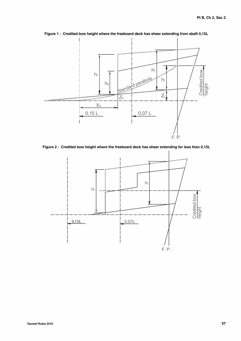
5.2.5 Where the forecastle height is less than one half ofthe standard height of superstructure, the credited bowheight may be determined as follows (hf in Fig 1 and Fig 2 isone half of the standard height of superstructure):
a) Where the freeboard deck has sheer extending fromabaft 0,15L, by a parabolic curve having its origin at0,15L abaft the forward perpendicular at a height equalto the midship depth of the ship, extended through thepoint of intersection of forecastle bulkhead and deck,and up to a point at the forward perpendicular nothigher than the level of the forecastle deck (as illustratedin Fig 1). However, if the value of the height denoted ht
in Fig 1 is smaller than the value of the height denotedhb then ht may be replaced by hb in the available bowheight, where:
Zb : as defined in Fig 1Zt : as defined in Fig 1
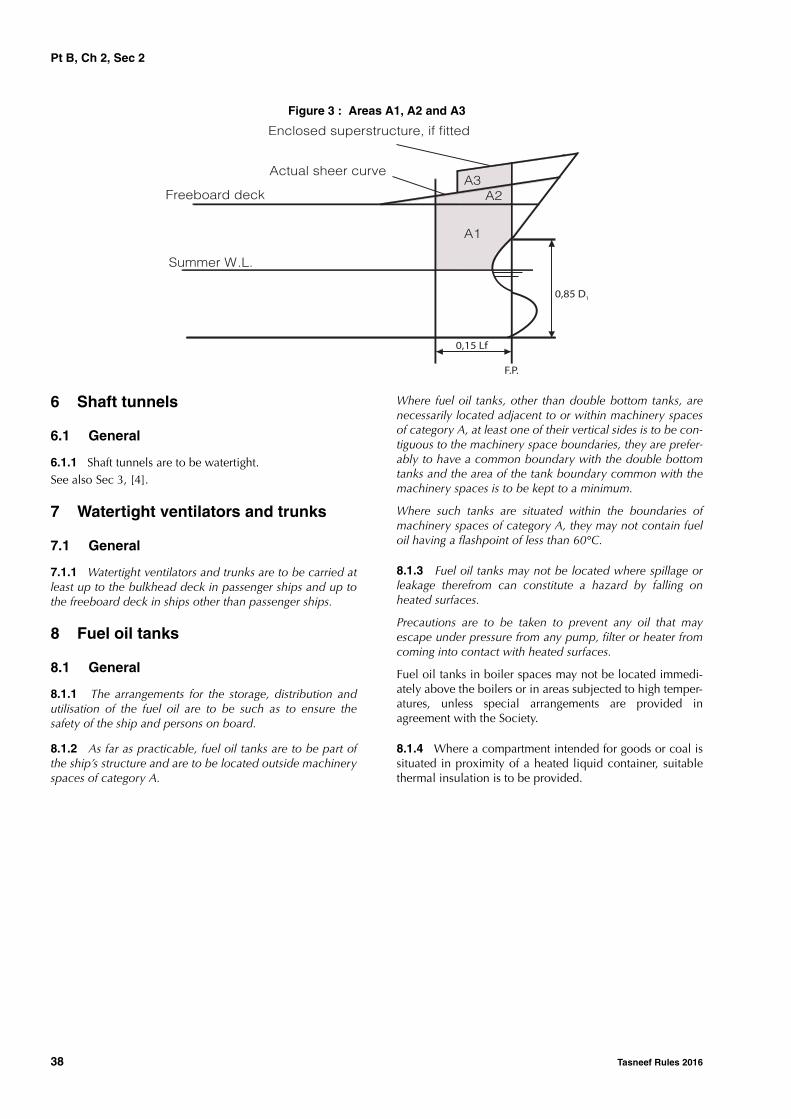
b) Where the freeboard deck has sheer extending for lessthan 0,15L or has no sheer, by a line from the forecastledeck at side at 0,07L extended parallel to the base lineto the forward perpendicular (as illustrated in Fig 2).
5.2.6 All ships assigned a type 'B' freeboard are to haveadditional reserve buoyancy in the fore end. Within therange of 0,15L abaft the forward perpendicular, the sum ofthe projected area between the summer load waterline andthe deck at side (A1 and A2 in Fig 3) and the projected areaof an enclosed superstructure, if fitted, (A3 in Fig 3) is not tobe less than:
[0.15Fmin + 4(LLL/3 + 10)] LLL/1000, in m2,
where:Fmin : coefficient, to be taken equal to:
Fmin = (F0 f1) + f2F0 : is the tabular freeboard, in mm, taken from the
International Convention Load Line in force,table 28.2, corrected for regulation 27(9) or27(10), as applicable
f1 : is the correction for block coefficient given inthe International Convention Load Line in force,regulation 30, and
f2 : is the correction for depth, in mm, given in theInternational Convention Load Line in force, reg-ulation 31.
Cb∇
LLLBT1
-----------------=
CwfAwf
LLL
2-------B-----------=
ht Zb0 15L,
xb
----------------
2
Zt–=
Pt B, Ch 2, Sec 2
Tasneef Rules 2016 37
Figure 1 : Credited bow height where the freeboard deck has sheer extending from abaft 0,15L
Figure 2 : Credited bow height where the freeboard deck has sheer extending for less than 0,15L
0,15 L
Xb
0,07 L
F. P.
Zt
ht
Zb
hb
hf
hf
Cre
dite
d b
owhe
ight
Standard parabola
hf
hf
0,15L 0,07L
F. P .
Cre
dite
d b
oxhe
i ght
Pt B, Ch 2, Sec 2
38 Tasneef Rules 2016
Figure 3 : Areas A1, A2 and A3
6 Shaft tunnels
6.1 General
6.1.1 Shaft tunnels are to be watertight.See also Sec 3, [4].
7 Watertight ventilators and trunks
7.1 General
7.1.1 Watertight ventilators and trunks are to be carried atleast up to the bulkhead deck in passenger ships and up tothe freeboard deck in ships other than passenger ships.
8 Fuel oil tanks
8.1 General
8.1.1 The arrangements for the storage, distribution andutilisation of the fuel oil are to be such as to ensure thesafety of the ship and persons on board.
8.1.2 As far as practicable, fuel oil tanks are to be part ofthe ship’s structure and are to be located outside machineryspaces of category A.
Where fuel oil tanks, other than double bottom tanks, arenecessarily located adjacent to or within machinery spacesof category A, at least one of their vertical sides is to be con-tiguous to the machinery space boundaries, they are prefer-ably to have a common boundary with the double bottomtanks and the area of the tank boundary common with themachinery spaces is to be kept to a minimum.
Where such tanks are situated within the boundaries ofmachinery spaces of category A, they may not contain fueloil having a flashpoint of less than 60°C.
8.1.3 Fuel oil tanks may not be located where spillage orleakage therefrom can constitute a hazard by falling onheated surfaces.
Precautions are to be taken to prevent any oil that mayescape under pressure from any pump, filter or heater fromcoming into contact with heated surfaces.
Fuel oil tanks in boiler spaces may not be located immedi-ately above the boilers or in areas subjected to high temper-atures, unless special arrangements are provided inagreement with the Society.
8.1.4 Where a compartment intended for goods or coal issituated in proximity of a heated liquid container, suitablethermal insulation is to be provided.
Summer W.L.
Freeboard deck
Actual sheer curve
Enclosed superstructure, if fitted
0,15 Lf
F.P.
0,85 D1
A3A2
A1

Pt B, Ch 2, Sec 3
Tasneef Rules 2016 39
SECTION 3 ACCESS ARRANGEMENT
1 General
1.1
1.1.1 The number and size of small hatchways for trim-ming and access openings to tanks or other enclosedspaces, are to be kept to the minimum consistent with thesatisfactory operation of the ship.
2 Double bottom
2.1 Inner bottom manholes
2.1.1 Inner bottom manholes are to be not less than 400mm x 400 mm. Their number and location are to be soarranged as to provide convenient access to any part of thedouble bottom.
2.1.2 Inner bottom manholes are to be closed by water-tight plate covers.
Doubling plates are to be fitted on the covers, wheresecured by bolts.
Where no ceiling is fitted, covers are to be adequately pro-tected from damage by the cargo.
2.2 Floor and girder manholes
2.2.1 Manholes are to be provided in floors and girders soas to provide convenient access to all parts of the doublebottom.
2.2.2 The size of manholes and lightening holes in floorsand girders is, in general, to be less than 50 per cent of thelocal height of the double bottom.
Where manholes of greater sizes are needed, edge rein-forcement by means of flat bar rings or other suitable stiffen-ers may be required.
2.2.3 Manholes may not be cut into the continuous centre-line girder or floors and girders below pillars, except whereallowed by the Society on a case by case basis.
3 Large cargo holds, large tanks and large water ballast tanks
3.1 General
3.1.1 Tanks in double bottom and in double side are gen-erally not to be considered as large water ballast tanks.
3.2 Access to tanks
3.2.1 Tanks with a length equal or greater than 35 m
Tanks and subdivisions of tanks having lengths of 35 m andabove are to be fitted with at least two access hatchwaysand ladders, as far apart as practicable longitudinally.
3.2.2 Tanks with a length less than 35 mTanks less than 35 m in length are to be served by at leastone access hatchway and ladder.
3.2.3 Dimensions of access hatchwaysThe dimensions of any access hatchway are to be sufficientto allow a person wearing a self-contained breathing appa-ratus to ascend or descend the ladder without obstructionand also to provide a clear opening to facilitate the hoistingof an injured person from the bottom of the tank. In no caseis the clear opening to be less than 600 mm x 600 mm.
3.2.4 Tanks subdivided by wash bulkheadsWhen a tank is subdivided by one or more wash bulkheads,at least two hatchways are to be fitted, and these hatchwaysare to be so located that the associated ladders effectivelyserve all subdivisions of the tank.
3.3 Access within tanks
3.3.1 Wash bulkheads in tanksWhere one or more wash bulkheads are fitted in a tank,they are to be provided with openings not less than 600 x800 mm and so arranged as to facilitate the access of per-sons wearing breathing apparatus or carrying a stretcherwith a patient.
3.3.2 Passage on the tank bottom To provide ease of movement on the tank bottom through-out the length and breadth of the tank, a passageway is tobe fitted on the upper part of the bottom structure of eachtank, or alternatively, manholes having at least the dimen-sions of 600 mm x 800 mm are to be arranged in the floorsat a height of not more than 600 mm from the bottom shellplating.
3.3.3 Passageways in the tanksa) Passageways in the tanks are to have a minimum width
of 600 mm considering the requirement for the possibil-ity of carrying an unconscious person. Elevated passage-ways are to be provided with guard rails over their entirelength. Where guard rails are provided on one side only,foot rails are to be fitted on the opposite side. Shelvesand platforms forming a part of the access to the tanksare to be of non-skid construction where practicableand be fitted with guard rails. Guard rails are to be fittedto bulkhead and side stringers when such structures arebeing used for recognised access.
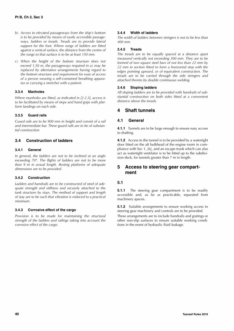
Pt B, Ch 2, Sec 3
40 Tasneef Rules 2016
b) Access to elevated passageways from the ship's bottomis to be provided by means of easily accessible passage-ways, ladders or treads. Treads are to provide lateralsupport for the foot. Where rungs of ladders are fittedagainst a vertical surface, the distance from the centre ofthe rungs to that surface is to be at least 150 mm.
c) When the height of the bottom structure does notexceed 1,50 m, the passageways required in a) may bereplaced by alternative arrangements having regard tothe bottom structure and requirement for ease of accessof a person wearing a self-contained breathing appara-tus or carrying a stretcher with a patient.
3.3.4 Manholes
Where manholes are fitted, as indicated in [2.2.2], access isto be facilitated by means of steps and hand grips with plat-form landings on each side.
3.3.5 Guard rails
Guard rails are to be 900 mm in height and consist of a railand intermediate bar. These guard rails are to be of substan-tial construction.
3.4 Construction of ladders
3.4.1 General
In general, the ladders are not to be inclined at an angleexceeding 70°. The flights of ladders are not to be morethan 9 m in actual length. Resting platforms of adequatedimensions are to be provided.
3.4.2 Construction
Ladders and handrails are to be constructed of steel of ade-quate strength and stiffness and securely attached to thetank structure by stays. The method of support and lengthof stay are to be such that vibration is reduced to a practicalminimum.
3.4.3 Corrosive effect of the cargo
Provision is to be made for maintaining the structuralstrength of the ladders and railings taking into account thecorrosive effect of the cargo.
3.4.4 Width of laddersThe width of ladders between stringers is not to be less than400 mm.
3.4.5 TreadsThe treads are to be equally spaced at a distance apartmeasured vertically not exceeding 300 mm. They are to beformed of two square steel bars of not less than 22 mm by22 mm in section fitted to form a horizontal step with theedges pointing upward, or of equivalent construction. Thetreads are to be carried through the side stringers andattached thereto by double continuous welding.
3.4.6 Sloping laddersAll sloping ladders are to be provided with handrails of sub-stantial construction on both sides fitted at a convenientdistance above the treads.
4 Shaft tunnels
4.1 General
4.1.1 Tunnels are to be large enough to ensure easy accessto shafting.
4.1.2 Access to the tunnel is to be provided by a watertightdoor fitted on the aft bulkhead of the engine room in com-pliance with Sec 1, [6], and an escape trunk which can alsoact as watertight ventilator is to be fitted up to the subdivi-sion deck, for tunnels greater than 7 m in length.
5 Access to steering gear compart-ment
5.1
5.1.1 The steering gear compartment is to be readilyaccessible and, as far as practicable, separated frommachinery spaces.
5.1.2 Suitable arrangements to ensure working access tosteering gear machinery and controls are to be provided.These arrangements are to include handrails and gratings orother non-slip surfaces to ensure suitable working condi-tions in the event of hydraulic fluid leakage.

Tasneef Rules 2016 41
Part BHull and Stability
Chapter 3
STABILITY
SECTION 1 GENERAL
SECTION 2 INTACT STABILITY
APPENDIX 1 INCLINING TEST AND LIGHTWEIGHT CHECK
APPENDIX 2 TRIM AND STABILITY BOOKLET


Pt B, Ch 3, Sec 1
Tasneef Rules 2016 43
SECTION 1 GENERAL
1 General
1.1 Application
1.1.1 GeneralAll ships equal to or greater than 24 m in length may beassigned class only after it has been demonstrated that theirintact stability is adequate for the service intended. Ade-quate intact stability means compliance with standards laiddown by the relevant Administration or with the require-ments specified in this Chapter taking into account theship’s size and type. In any case, the level of intact stabilityis not to be less than that provided by the Rules.
1.1.2 Ships less than 24 m in lengthThe Rules also apply to ships less than 24 m in length. Inthis case, the requirements concerned may be partiallyomitted subject to the agreement of the Society.
1.1.3 Approval of the AdministrationWhen the Administration of the State whose flag the ship isentitled to fly has issued specific rules covering stability, theSociety may accept such rules for classification purposes inlieu of those given in this Chapter.
Evidence of approval of the stability by the Administrationconcerned may be accepted for the purpose of classifica-tion.
In cases of application of the above requirements an appro-priate entry is made in the classification files of the ship.
2 Definitions
2.1 General
2.1.1 For the purpose of this Chapter 3 the definitionsgiven in the International Code on Intact Stability, 2008(IMO Resolution MSC.267(85)) apply. The definitions in[2.2] to [2.7] are given for ease of reference.
2.2 Length of ship
2.2.1 The length is to be taken as 96% of the total lengthon a waterline at 85% of the least moulded depth measuredfrom the top of the keel, or as the length from the foreside ofthe stem to the axis of the rudder stock on the waterline, ifthat is greater. In ships designed with a rake of keel, thewaterline on which this length is measured is to be parallelto the designed waterline.
2.3 Moulded breadth
2.3.1 The moulded breadth is the maximum breadth of theship measured amidships to the moulded line of the frame
in a ship with a metal shell and to the outer surface of thehull in a ship with a shell of any other material.
2.4 Moulded depth
2.4.1 The moulded depth is the vertical distance measuredfrom the top of the keel to the top of the freeboard deckbeam at side. In wood and composite ships, the distance ismeasured from the lower edge of the keel rabbet. Wherethe form at the lower part of the midship section is of a hol-low character, or where thick garboards are fitted, the dis-tance is measured from the point where the line of the flatof the bottom continued inwards cuts the side of the keel. Inships having rounded gunwales, the moulded depth is to bemeasured to the point of intersection of the moulded linesof the deck and side shell plating, the lines extending asthough the gunwale were of angular design. Where thefreeboard deck is stepped and the raised part of the deckextends over the point at which the moulded depth is to bedetermined, the moulded depth is to be measured to a lineof reference extending from the lower part of the deck alonga line parallel with the raised part.
2.5 Timber
2.5.1 Timber means sawn wood or lumber, cants, logs,poles, pulpwood and all other types of timber in loose orpackaged forms. The term does not include wood pulp orsimilar cargo.
2.6 Timber deck cargo
2.6.1 Timber deck cargo means a cargo of timber carriedon an uncovered part of a freeboard or superstructure deck.The term does not include wood pulp or similar cargo.
2.7 Timber load line
2.7.1 Timber load line means a special load line assignedto ships complying with certain conditions related to theirconstruction set out in the International Convention onLoad Lines 1966, as amended, and used when the cargocomplies with the stowage and securing conditions of theCode of Safe Practice for Ships Carrying Timber Deck Car-goes, 2011 (IMO Resolution A.1048(27)).
3 Examination procedure
3.1 Documents to be submitted
3.1.1 List of documentsFor the purpose of the examination of the stability, the doc-umentation listed in Ch 1, Sec 3, [1.1.2] is to be submittedfor information.
Pt B, Ch 3, Sec 1
44 Tasneef Rules 2016
The stability documentation to be submitted for approval isas follows:
a) Inclining test report for the ship, as required in [3.2] or:
• where the stability data is based on a sister ship, theinclining test report of that sister ship along with thelightship measurement report for the ship in ques-tion; or
• where lightship particulars are determined by meth-ods other than inclining of the ship or its sister, thelightship measurement report of the ship along witha summary of the method used to determine thoseparticulars as indicated in [3.2.4].
b) trim and stability booklet, as required in Sec 2, [1.1.1]
c) and, as applicable:
• grain loading manual, as required in Pt E, Ch 4,Sec 3, [2.2.2]
• loading computer documentation, as required inSec 2, [1.1.2] and in Pt F, Ch 13, Sec 11, [2.1.2].
A copy of the trim and stability booklet and, if applicable,the grain stability booklet or the loading computer docu-mentation is to be available on board for the attention of theMaster.
3.1.2 Provisional documentationThe Society reserves the right to accept or demand the sub-mission of provisional stability documentation for examina-tion.
Provisional stability documentation includes loading condi-tions based on estimated lightship values.
3.1.3 Final documentationFinal stability documentation based on the results of theinclining test or the lightweight check is to be submitted forexamination.
When provisional stability documentation has already beensubmitted and the difference between the estimated valuesof the lightship and those obtained after completion of thetest is less than:
• 2% for the displacement, and,
• 1% of the length between perpendiculars for the longi-tudinal position of the centre of gravity,
and the determined vertical position of the centre of gravityis not greater than the estimated vertical position of the cen-tre of gravity, the provisional stability documentation maybe accepted as the final stability documentation.
3.2 Inclining test/lightweight check
3.2.1 Definitions
a) Lightship
The lightship is a ship complete in all respects, but with-out consumables, stores, cargo, and crew and effects,and without any liquids on board except for machineryand piping fluids, such as lubricants and hydraulics,which are at operating levels.
b) Inclining test
The inclining test is a procedure which involves movinga series of known weights, normally in the transverse
direction, and then measuring the resulting change inthe equilibrium heel angle of the ship. By using thisinformation and applying basic naval architecture prin-ciples, the ship's vertical centre of gravity (VCG or KG)is determined.
c) Lightweight checkThe lightweight check is a procedure which involvesauditing all items which are to be added, deducted orrelocated on the ship at the time of the inclining test sothat the observed condition of the ship can be adjustedto the lightship condition. The weight and longitudinal,transverse and vertical location of each item are to beaccurately determined and recorded. The lightship dis-placement and longitudinal centre of gravity (LCG) canbe obtained using this information, as well as the staticwaterline of the ship at the time of the inclining test asdetermined by measuring the freeboard or verifieddraught marks of the ship, the ship's hydrostatic dataand the sea water density.
3.2.2 GeneralAny ship for which a stability investigation is requested inorder to comply with class requirements is to be initiallysubject to an inclining test permitting the evaluation of theposition of the lightship centre of gravity so that the stabilitydata can be determined.
The inclining test or lightweight check (see [3.2.4]) is to beattended by a Surveyor of the Society. The Society mayaccept inclining tests or lightweight checks attended by amember of the flag Administration.
For cargo ships having length less than 24 metres, irrespec-tive of their navigation, at the discretion of the Society,instead of the inclining test one or more practical stabilitytest(s) relevant to the most severe conditions foreseen in realservice may be carried out.
In such cases a report is to be prepared relevant to thetested loading conditions containing restrictions in the load-ing conditions and/or in ballasting, if any, which, dulyapproved by the Society, is to replace the prescribed stabil-ity booklet.
3.2.3 Inclining testThe inclining test is required in the following cases:• Any new passenger ship regardless of size and any new
cargo ship having length of 24 m and upwards, after itscompletion, except for the cases specified in [3.2.4]
• Any ship, if deemed necessary by the Society where anyalterations are made so as to materially affect the stabil-ity.
3.2.4 Lightweight check The Society may allow a lightweight check to be carried outin lieu of an inclining test in one of the following cases:
a) an individual cargo ship, provided basic stability dataare available from the inclining test of a sister ship and alightweight check is performed in order to prove that thesister ship corresponds to the prototype ship. The light-weight check is to be carried out upon the ship's com-pletion. The final stability data to be considered for thesister ship in terms of displacement and position of thecentre of gravity are those of the prototype. Whenever,

Pt B, Ch 3, Sec 1
Tasneef Rules 2016 45
in comparison with the data derived from the prototype,a deviation from the lightship displacement exceeding1% for ships of 160 m or more in length, or 2% for shipsof 50 m or less in length, or as determined by linearinterpolation for intermediate lengths, or a deviationfrom the lightship longitudinal centre of gravity exceed-ing 0,5% of Ls is found, the ship is to be inclined;
b) barges and pontoons without superstructures, not sub-ject to SOLAS Convention, provided that the verticalcentre of gravity is considered at the level of the deck;
c) barges and pontoons with superstructures, not subject tothe SOLAS Convention, provided that the vertical centre
of gravity is assumed at a position considered suitableby the Society on the basis of the ship's geometry;
d) other ship types, not subject to SOLAS Convention andfor which the execution of an inclining test may not befeasible, provided that a detailed list of weights and thepositions of their centres of gravity is submitted. Thecorrectness of the estimated values will be checked onthe basis of the results of the lightweight check.
3.2.5 Detailed procedure
A detailed procedure for conducting an inclining test isincluded in App 1. For the lightweight check, the same pro-cedure applies except as provided for in App 1, [1.1.8].

Pt B, Ch 3, Sec 2
46 Tasneef Rules 2016
SECTION 2 INTACT STABILITY
1 General
1.1 Information for the Master
1.1.1 Stability bookletEach ship is to be provided with a stability booklet,approved by the Society, which contains sufficient informa-tion to enable the Master to operate the ship in compliancewith the applicable requirements contained in this Section.
If a stability instrument is used as a supplement to the stabil-ity booklet for the purpose of determining compliance withthe relevant stability criteria such instrument is to be subjectto approval by the Society (see Ch 11, Sec 2, [4.5]).
Where any alterations are made to a ship so as to materiallyaffect the stability information supplied to the Master,amended stability information is to be provided. If neces-sary the ship is to be re-inclined.
Stability data and associated plans are to be drawn up inthe working language of the ship and any other languagethe Administration the flag of which the ship is entitled to flymay require.
The format of the trim and stability booklet and the informa-tion included are specified in App 2.
If curves or tables of minimum operational metacentricheight (GM) or maximum centre of gravity (VCG) are usedto ensure compliance with the relevant intact stability crite-ria those limiting curves are to extend over the full range ofoperational trims, unless the Society agrees that trim effectsare not significant. When curves or tables of minimum oper-ational metacentric height (GM) or maximum centre ofgravity (VCG) versus draught covering the operational trimsare not available, the Master is to verify that the operatingcondition does not deviate from a studied loading condi-tion, or verify by calculation that the stability criteria are sat-isfied for this loading condition taking into account trimeffects.
1.1.2 Loading instrumentAs a supplement to the approved stability booklet, a loadinginstrument, approved by the Society, may be used to facili-tate the stability calculations mentioned in App 2.
A simple and straightforward instruction manual is to beprovided.
In order to validate the proper functioning of the computersoftware, pre-defined loading conditions are to be run inthe loading instrument periodically, at least at every period-ical class survey, and the print-out is to be maintained onboard as check conditions for future reference in addition tothe approved test conditions booklet.
The procedure to be followed, as well as the list of technicaldetails to be sent in order to obtain loading instrumentapproval, are given in Ch 11, Sec 2, [4].
1.1.3 Operating booklets for certain shipsSpecial purpose ships and novel craft are to be providedwith additional information in the stability booklet such asdesign limitations, maximum speed, worst intended weatherconditions or other information regarding the handling ofthe craft that the Master needs to operate the ship safely.
1.2 Permanent ballast
1.2.1 If used, permanent ballast is to be located in accord-ance with a plan approved by the Society and in a mannerthat prevents shifting of position. Permanent ballast is not tobe removed from the ship or relocated within the ship with-out the approval of the Society. Permanent ballast particu-lars are to be noted in the ship’s stability booklet.
1.2.2 Permanent solid ballast is to be installed under thesupervision of the Society.
1.3 Still waters
1.3.1 Still waters are, generally, sheets of water within amile of the shore, distinguished by a wind scale not higherthan 2 Beaufort, light breeze 4-6 knots, sea scale 2 (slightsea), mean height of waves 0,10-0,50 m.
2 Design criteria
2.1 General intact stability criteria
2.1.1 GeneralThe intact stability criteria specified in [2.1.2], [2.1.3],[2.1.4] and [2.1.5] are to be complied with for the loadingconditions mentioned in App 2, [1.2].
However, the lightship condition not being an operationalloading case, the Society may accept that part of the above-mentioned criteria are not fulfilled.
These criteria set minimum values, but no maximum valuesare recommended. It is advisable to avoid excessive valuesof metacentric height, since these might lead to accelerationforces which could be prejudicial to the ship, its equipmentand to safe carriage of the cargo.
For ships of length less than 24 m, except passenger ships,and ships of any length classed to sail in still waters, insteadof the stability criteria specified in [2.1.2], [2.1.3] and[2.1.4], only the criterion mentioned in [2.1.5] b) is to becomplied with.
Where anti-rolling devices are installed in a ship, the Societyis to be satisfied that the criteria can be maintained whenthe devices are in operation and that failure of the powersupply or the failure of the device(s) will not result in thevessel being unable to meet the relevant provisions of thisChapter.
Pt B, Ch 3, Sec 2
Tasneef Rules 2016 47
2.1.2 GZ curve area
The area under the righting lever curve (GZ curve) is to benot less than 0,055 m.rad up to θ = 30° angle of heel andnot less than 0,09 m.rad up to θ = 40° or the angle of downflooding θf if this angle is less than 40°. Additionally, thearea under the righting lever curve (GZ curve) between theangles of heel of 30° and 40° or between 30°and θf, if thisangle is less than 40°, is to be not less than 0,03 m.rad.
Note 1: θf is an angle of heel at which openings in the hull, super-structures or deckhouses which cannot be closed weathertight sub-merge. In applying this criterion, small openings through whichprogressive flooding cannot take place need not be considered as
open.
2.1.3 Minimum righting lever
The righting lever GZ is to be at least 0,20 m at an angle ofheel equal to or greater than 30°.
2.1.4 Angle of maximum righting lever
The maximum righting lever is to occur at an angle of heelnot less than 25°. If this is not practicable, alternative crite-ria, based on an equivalent level of safety, may be appliedsubject to the approval of the Society.
When the righting lever curve has a shape with two maxi-mums, the first is to be located at a heel angle not less than25°.
In cases of ships with a particular design, the Society mayaccept an angle of heel θmax less than 25° but in no case lessthan 15°, provided that the area “A” below the righting levercurve is not less than the value obtained, in m.rad, from thefollowing formula:
where θmax is the angle of heel in degrees at which the right-ing lever curve reaches its maximum.
2.1.5 Initial metacentric height
a) The initial metacentric height GM0 is not to be less than0,15 m.
b) For ships of length less than 24 m, except passengerships, and ships of any lenght classed to sail in stillwaters, the initial metacentric height GMo is not to beless than 0,35 m, except in the lightship condition.
2.1.6 Elements affecting stability
A number of influences such as icing of topsides, watertrapped on deck, etc., adversely affect stability and are tobe taken into account, so far as is deemed necessary by theSociety.
2.1.7 Elements reducing stability
Provisions are to be made for a safe margin of stability at allstages of the voyage, regard being given to additions ofweight, such as those due to absorption of water and icing(details regarding ice accretion are given in [6]) and to
losses of weight such as those due to consumption of fueland stores.
3 Severe wind and rolling criterion (weather criterion)
3.1 Scope
3.1.1 This criterion supplements the stability criteria givenin [2.1] for ships of 24 m in length and over. The more strin-gent criteria of [2.1] and the weather criterion are to governthe minimum requirements.
3.2 Weather criterion
3.2.1 Assumptions
The ability of a ship to withstand the combined effects ofbeam wind and rolling is to be demonstrated for eachstandard condition of loading, with reference to Fig 1 as fol-lows:
• the ship is subjected to a steady wind pressure actingperpendicular to the ship's centreline which results in asteady wind heeling lever (w1);
• from the resultant angle of equilibrium (θ0), the ship isassumed to roll owing to wave action to an angle of roll(θ1) to windward. The angle of heel under action ofsteady wind (θ0) is not to exceed 16° or 80% of theangle of deck edge immersion, whichever is less;
• the ship is then subjected to a gust wind pressure whichresults in a gust wind heeling lever (w2);
• under these circumstances, area b is to be equal to orgreater than area a, as indicated in Fig 1, where theangles in Fig 1 are defined as follows:
• θ0 : Angle of heel, in degrees, under actionof steady wind
• θ1 : Angle of roll, in degrees, to windwarddue to wave action, calculated accord-ing to [3.2.4]
• θ2 : Angle of downflooding (θf) in degrees,or 50° or θc , whichever is less
where:
• θf : Angle of heel in degrees, at whichopenings in the hull, superstructuresor deckhouses which cannot beclosed weathertight immerse. Inapplying this criterion, small open-ings through which progressiveflooding cannot take place need notbe considered as open;
• θc : Angle in degrees, of second interceptbetween wind heeling lever w2 andGZ curves
A 0 055, 0 001 30° θmax–( ),+=

Pt B, Ch 3, Sec 2
48 Tasneef Rules 2016
Figure 1 : Severe wind and rolling
a: area above the GZ curve and below w2, between θR and the
intersection of w2 with the GZ curve
b: area above the heeling lever w2 and below the GZ curve,
between the intersection of w2 with the GZ curve and 2.
3.2.2 Heeling leversThe wind heeling levers w1 and w2, in m, referred to in[3.2.1], are constant values at all angles of inclination andare to be calculated as follows:
and
where:P : wind pressure of 504 N/m2. The value of P used
for ships with restricted navigation notation maybe reduced subject to the approval of the Soci-ety;
A : Projected lateral area in m2, of the portion of theship and deck cargo above the waterline;
Z : Vertical distance in m, from the centre of A tothe centre of the underwater lateral area orapproximately to a point at one half the meandraught;
Δ : Displacement, in t;g : gravitational acceleration of 9,81 m/s2.
3.2.3 Alternative criteria Alternative means for determining the wind heeling lever(w1) may be accepted, to the satisfaction of the Society, asequivalent to the calculation in [3.2.2]. When such alterna-tive tests are carried out, reference is to be to MSC/Circ.1200 "Interim Guidelines for alternative assessment of theweather criterion". The wind velocity used in the tests is tobe 26 m/s in full scale with uniform velocity profile. Thevalue of wind velocity used for ships engaged in restrictedservices may be reduced to the satisfaction of the Society.
3.2.4 Angles of rollThe angle of roll θ1, in degrees, (see Note 1) referred to in[3.2.1] is to be calculated as follows:
where:
X1 : Coefficient defined in Tab 1
X2 : Coefficient defined in Tab 2
k : Coefficient:
k = 1,0 for a round-bilged ship having no bilgeor bar keels
k = 0,7 for a ship having sharp bilge
k = as shown in Tab 3 for a ship having bilgekeels, a bar keel or both.
with:
OG : KG - d
KG : Height of centre of gravity above baseline, in m
d : Mean moulded draught of the ship, in m
s : Factor defined in Tab 4, where T is the ship rollnatural period, in s. In absence of sufficientinformation, the following formula can be used:
where:
The symbols in the tables and formula for the rolling periodare defined as follows:
Lw : Length of the ship at the waterline, in m
b : Moulded breadth of ship, in m
d : Mean moulded draught of the ship, in m
Cb : Block coefficient
AK : Total overall area of bilge keels, or area of thelateral projection of the bar keel, or sum of theseareas, or area of the lateral projection of anyhull appendages generating added mass duringship roll, in m2
GM : Metacentric height corrected for free surfaceeffect, in m.
Note 1: The angle of roll for ships with anti-rolling devices is to bedetermined without taking into account the operation of thesedevices unless the Society is satisfied with the proof that the devicesare effective even with sudden shutdown of their supplied power.
3.2.5 Application criteria Tables and formulae above are based on data from shipshaving:
• B/d smaller than 3,5
• (KG/d-1) between -0,3 and 0,5
• T smaller than 20 s.
For ships with parameters outside of the above limits theangle of roll (θ1) may be determined with model experi-ments of a subject ship with the procedure described inMSC.1/Circ. 1200 "Interim Guidelines for alternative assess-ment of the weather criterion" as the alternative. In addi-tion, the Society may accept such alternativedeterminations for any ship, if deemed appropriate.
Leve
r
Angle of heel
GZ
θ0
θ1
θ2 θca
b
�w1�w2
W1PAZ
1000gΔ--------------------=
W2 1 5, W1=
θ1 109kX1X2 rs=
r 0 73 0 6, OG( ) d⁄+,=
T 2CBGM
--------------=
C 0 373, 0 023,Bd--- 0 043,
LW
100---------- –+=

Pt B, Ch 3, Sec 2
Tasneef Rules 2016 49
4 Effects of free surfaces of liquids in tanks
4.1 General
4.1.1 For all loading conditions, the initial metacentricheight and the righting lever curve are to be corrected forthe effect of free surfaces of liquids in tanks.
4.2 Consideration of free surface effects
4.2.1 Free surface effects are to be considered wheneverthe filling level in a tank is less than 98% of full condition.Free surface effects need not be considered where a tank isnominally full, i.e. filling level is 98% or above. However,nominally full cargo tanks are to be corrected for free sur-face effects at 98% filling level. In doing so, the correctionto initial metacentric height is to be based on the inertiamoment of liquid surface at 5° of heeling angle divided bydisplacement, and the correction to righting lever is to be ingeneral on the basis of real shifting moment of cargo liquids.
4.2.2 Free surface effects for small tanks may be ignoredunder the condition in [4.8.1].
Table 1 : Values of coefficient X1
Table 2 : Values of coefficient X2
Table 3 : Values of coefficient k
Table 4 : Values of factor s
(Intermediate values in these tables are to be obtained bylinear interpolation)
4.3 Categories of tanks
4.3.1 Tanks which are taken into consideration whendetermining the free surface correction may be one of twocategories:
• Tanks with fixed filling level (e.g. liquid cargo, water bal-last). The free surface correction is to be defined for theactual filling level to be used in each tank.
• Tanks with variable filling level (e.g. consumable liquidssuch as fuel oil, diesel oil, and fresh water, and also liq-uid cargo and water ballast during liquid transfer opera-tions). Except as permitted in [4.5.1] and [4.6.1], the freesurface correction is to be the maximum value attaina-ble among the filling limits envisaged for each tank, con-sistent with any operating instructions.
4.4 Consumable liquids
4.4.1 In calculating the free surfaces effect in tanks con-taining consumable liquids, it is to be assumed that for eachtype of liquid at least one transverse pair or a single cen-treline tank has a free surface and the tank or combinationof tanks taken into account are to be those where the effectof free surface is the greatest.
B/d X1
≤ 2,4 1,00
2,5 0,98
2,6 0,96
2,7 0,95
2,8 0,93
2,9 0,91
3,0 0,90
3,1 0,88
3,2 0,86
3,4 0,82
≥ 3,5 0,80
CB X2
≤ 0,45 0,75
0,50 0,82
0,55 0,89
0,60 0,95
0,65 0,97
≥ 0,70 1,00
k
0,0 1,00
1,0 0,98
1,5 0,95
2,0 0,88
2,5 0,79
3,0 0,74
3,5 0,72
≥ 4,0 0,70
T s
≤ 6 0,100
7 0,098
8 0,093
12 0,065
14 0,053
16 0,044
18 0,038
≥ 20 0,035
AK 100×Lw B×
----------------------

Pt B, Ch 3, Sec 2
50 Tasneef Rules 2016
4.5 Water ballast tanks
4.5.1 Where water ballast tanks, including anti-rollingtanks and anti-heeling tanks, are to be filled or dischargedduring the course of a voyage, the free surfaces effect is tobe calculated to take account of the most onerous transitorystage relating to such operations.
4.6 Liquid transfer operations
4.6.1 For ships engaged in liquid transfer operations, thefree surface corrections at any stage of the liquid transferoperations may be determined in accordance with the fillinglevel in each tank at the stage of the transfer operation.
Note 1: A sufficient number of loading conditions representing theinitial, intermediate and final stages of the filling or discharge opera-tion using the free surface correction at the filling level in each tankat the considered stage may be evaluated to fulfil this recommenda-tion.
4.7 GM0 and GZ curve corrections
4.7.1 The corrections to the initial metacentric height andto the righting lever curve are to be addressed separately asindicated in [4.7.2] and [4.7.3].
4.7.2 In determining the correction to the initial metacen-tric height, the transverse moments of inertia of the tanksare to be calculated at 0 degrees angle of heel according tothe categories indicated in [4.3.1].
4.7.3 The righting lever curve may be corrected by any ofthe following methods:
• Correction based on the actual moment of fluid transferfor each angle of heel calculated;
• Correction based on the moment of inertia, calculatedat 0 degrees angle of heel, modified at each angle ofheel calculated.
Corrections may be calculated according to the categoriesindicated in [4.2.1].
4.7.4 Whichever method is selected for correcting therighting lever curve, only that method is to be presented inthe ship’s trim and stability booklet. However, where analternative method is described for use in manually calcu-lated loading conditions, an explanation of the differenceswhich may be found in the results, as well as an examplecorrection for each alternative, are to be included.
4.8 Small tanks
4.8.1 Small tanks which satisfy the following condition cor-responding to an angle of inclination of 30° need not beincluded in the correction:
where:
Mfs : Free surface moment, in m
Δmin : Minimum ship displacement, in t, calculated atdmin
dmin : Minimum mean service draught, in m, of shipwithout cargo, with 10% stores and minimumwater ballast, if required.
4.9 Remainder of liquid
4.9.1 The usual remainder of liquids in the empty tanksneed not be taken into account in calculating the correc-tions, providing the total of such residual liquids does notconstitute a significant free surface effect.
5 Cargo ships carrying timber deck cargoes
5.1 Application
5.1.1 The provisions given hereunder apply to all ships of24 m in length and over engaged in the carriage of timberdeck cargoes. Ships that are provided with and make use oftheir timber load line are also to comply with the require-ments of regulations 41 to 45 of the International Load LineConvention 1966, as amended.
5.2 Stability criteria
5.2.1 For ships loaded with timber deck cargoes and pro-vided that the cargo extends longitudinally between super-structures (where there is no limiting superstructure at theafter end, the timber deck cargo is to extend at least to theafter end of the aftermost hatchway) and transversely forthe full beam of ship after due allowance for a rounded gun-wale not exceeding 4% of the breadth of the ship and/orsecuring the supporting uprights and which remainssecurely fixed at large angles of heel, the Society may applythe criteria given in [5.2.2] to [5.2.5], which substitutethose given in [2.1.2], [2.1.3], [2.1.4] and [2.1.5] and in [3].
5.2.2 The area under the righting lever curve (GZ curve) isto be not less than 0.08 m.rad up to θ = 40° or the angle offlooding if this angle is less than 40°.
5.2.3 The maximum value of the righting lever (GZ) is tobe at least 0,25 m.
5.2.4 At all times during a voyage, the metacentric heightGM0 is to be not less than 0,1 m taking into account theabsorption of water by the deck cargo and/or ice accretionon the exposed surfaces. (Details regarding ice accretionare given in [6]).
5.2.5 When determining the ability of the ship to with-stand the combined effect of beam wind and rolling accord-ing to [3], the 16° limiting angle of heel under action ofsteady wind is to be complied with, but the additional crite-rion of 80% of the angle of deck edge immersion may beignored.
Mfs Δmin⁄ 0 01 m,<

Pt B, Ch 3, Sec 2
Tasneef Rules 2016 51
5.3 Stability booklet
5.3.1 The ship is to be supplied with comprehensive stabil-ity information which takes into account timber deck cargo.Such information is to enable the Master, rapidly and sim-ply, to obtain accurate guidance as to the stability of theship under varying conditions of service. Comprehensiverolling period tables or diagrams have proved to be veryuseful aids in verifying the actual stability conditions.
5.3.2 The Society may deem it necessary that the Masterbe given information setting out the changes in deck cargofrom that shown in the loading conditions, when the perme-ability of the deck cargo is significantly different from 25%(see [5.4.1]).
5.3.3 Conditions are to be shown indicating the maximumpermissible amount of deck cargo having regard to the light-est stowage rate likely to be met in service.
5.4 Calculation of the stability curve
5.4.1 In addition to the provisions given in App 2, [1.3],the Society may allow account to be taken of the buoyancyof the deck cargo assuming that such cargo has a permea-bility of 25% of the volume occupied by the cargo. Addi-tional curves of stability may be required if the Societyconsiders it necessary to investigate the influence of differ-ent permeabilities and/or assumed effective height of thedeck cargo.
5.5 Loading conditions to be considered
5.5.1 The loading conditions which are to be consideredfor ships carrying timber deck cargoes are specified inApp 2, [1.2.2]. For the purpose of these loading conditions,the ship is assumed to be loaded to the summer timber loadline with water ballast tanks empty.
5.6 Assumptions for calculating loading conditions
5.6.1 The following assumptions are to be made for calcu-lating the loading conditions referred to in App 2, [1.2.2]:
• the amount of cargo and ballast is to correspond to theworst service condition in which all the relevant stabilitycriteria reported in [2.1.2], [2.1.3], [2.1.4] and [2.1.5], orthe optional criteria given in [5.2], are met.
• In the arrival condition, it is to be assumed that theweight of the deck cargo has increased by 10% due towater absorption.
5.6.2 The stability of the ship at all times, including duringthe process of loading and unloading timber deck cargo, isto be positive and in compliance with the stability criteria of[5.2]. It is to be calculated having regard to:
• the increased weight of the timber deck cargo due to:- absorption of water in dried or seasoned timber, and- ice accretion, if applicable (as reported in [6])
• variations in consumable• the free surface effect of liquid in tanks, and• the weight of water trapped in broken spaces within the
timber deck cargo and especially logs.
5.6.3 Excessive initial stability is to be avoided as it willresult in rapid and violent motion in heavy seas which willimpose large sliding and racking forces on the cargo causinghigh stresses on the lashings. Unless otherwise stated in thestability booklet, the metacentric height is generally not toexceed 3% of the breadth in order to prevent excessiveacceleration in rolling provided that the relevant stability cri-teria given in [5.2] are satisfied.
5.7 Stowage of timber deck cargoes
5.7.1 The stowage of timber deck cargoes is to complywith the provisions of chapter 3 of the Code of Safe Practicefor Ships Carrying Timber Deck Cargoes, 2011 (IMO Reso-lution A.1048(27)).
6 Icing
6.1 General
6.1.1 Ice formation is a complicated process whichdepends upon meteorological conditions, condition of load-ing and behaviour of the ship in stormy weather as well ason the size and location of superstructures and rigging. Themost common cause of ice formation is the deposit of waterdroplets on the ship's structure. These droplets come fromspray driven from wave crests and from ship-generatedspray.
6.1.2 Ice formation may also occur in conditions of snow-fall, sea fog including arctic sea smoke, a drastic fall in ambi-ent temperature, as well as from the freezing of drops ofrain on impact with the ship's structure.
6.1.3 Ice formation may sometimes be caused or accentu-ated by water shipped on board and retained on deck.
6.1.4 Intensive ice formation generally occurs on stem,bulwark and bulwark rail, front walls of superstructures anddeckhouses, hawse holes, anchors, deck gear, forecastledeck and upper deck, freeing ports, aerials, stays, shrouds,masts and spars.
6.1.5 The most dangerous areas as far as ice formation isconcerned are the sub-Arctic regions.
6.1.6 The most intensive ice formation takes place whenwind and sea come from ahead. In beam and quarteringwinds, ice accumulates quicker on the windward side of theship, thus leading to a constant list which can be extremelydangerous.
6.1.7 Listed below are meteorological conditions causingthe most common type of ice formation due to spraying of aship.

Pt B, Ch 3, Sec 2
52 Tasneef Rules 2016
a) Slow accumulations of ice take place:
• at ambient temperature from -1°C to -3°C and anywind force
• at ambient temperature -4°C and lower and windforce from 0 to 9 m/s
• under the conditions of precipitation, fog or sea mistfollowed by a drastic fall of the ambient tempera-ture.
b) At ambient temperature of -4°C to -8°C and wind force10-15 m/s, rapid accumulation of ice takes place.Under these conditions the intensity of ice accumulationcan reach three times the amount normally accumu-lated in a).
c) Very fast accumulation of ice takes place:
• at ambient temperature of -4°C and lower and windforces of 16 m/s and over
• at ambient temperature -9°C and lower and windforce 10 to 15 m/s.
6.2 Icing accumulation consequences
6.2.1 Ice formation adversely affects the seaworthiness ofthe ship as ice formation leads to:
• an increase in the weight of the ship due to accumula-tion of ice on the ship's surfaces which may cause thereduction of freeboard and buoyancy
• a rise of the ship's centre of gravity due to the high loca-tion of ice on the ship's structures with correspondingreduction in the level of stability
• an increase of windage area due to ice formation on theupper parts of the ship and hence an increase in theheeling moment due to the action of the wind
• the development of a constant list due to uneven distri-bution of ice across the breadth of the ship
• impairment of the manoeuvrability and reduction of thespeed of the ship.
6.3 Application
6.3.1 For any ship operating in areas where ice accretion islikely to occur, adversely affecting a ship's stability, icingallowances are to be included in the analysis of conditionsof loading.
6.3.2 The Society is concerned to take icing into accountand may apply national standards where environmentalconditions warrant higher standards than those specified inthe following regulations.
6.4 Ships carrying timber deck cargoes
6.4.1 The Master is to establish or verify the stability of hisship for the worst service condition, having regard to theincreased weight of deck cargo due to water absorptionand/or ice accretion and to variations in consumable.
6.4.2 When timber deck cargoes are carried and it is antic-ipated that some formation of ice will take place, an allow-ance is to be made in the arrival condition for the additionalweight.
6.5 Calculation assumptions
6.5.1 For ships operating in areas where ice accretion islikely to occur, the following icing allowance is to be madein the stability calculations:
• 30 kg per square metre on exposed weather decks andgangways
• 7,5 kg per square metre for the projected lateral area ofeach side of the ship above the water plane
• the projected lateral area of discontinuous surfaces ofrail, sundry booms, spars (except masts) and rigging ofships having no sails and the projected lateral area ofother small objects are to be computed by increasingthe total projected area of continuous surfaces by 5%and the static moments of this area by 10%.
6.5.2 Ships intended for operation in areas where ice isknown to occur are to be:
• designed to minimise the accretion of ice, and
• equipped with such means for removing ice as, forexample, electrical and pneumatic devices, and/or spe-cial tools such as axes or wooden clubs for removing icefrom bulwarks, rails and erections.
6.6 Guidance relating to ice accretion
6.6.1 The following icing areas are to be considered:
a) the area north of latitude 65°30'N, between longitude28°W and the west coast of Iceland; north of the northcoast of Iceland; north of the rhumb line running fromlatitude 66°N, longitude 15°W to latitude 73°30'N, lon-gitude 15°E, north of latitude 73°30'N between longi-tude 15°E and 35°E, and east of longitude 35°E, as wellas north of latitude 56°N in the Baltic Sea;
b) the area north of latitude 43°N bounded in the west bythe North American coast and the east by the rhumbline running from latitude 43°N, longitude 48°W to lati-tude 63°N, longitude 28°W and thence along longitude28°W;
c) all sea areas north of the North American Continent,west of the areas defined in a) and b);
d) the Bering and Okhotsk Seas and the Tartary Strait dur-ing the icing season; and
e) south of latitude 60°S.
6.6.2 For ships operating where ice accretion may beexpected:
• within the areas defined in a), c), d) and e) of [6.6.1]known to having icing conditions significantly differentfrom those described in [6.5], ice accretion require-ments of one half to twice the required allowance maybe applied;
• within the area defined in b), where ice accretion inexcess of twice the allowance required by [6.5] may beexpected, more severe requirements than those given in[6.5] may be applied.
Pt B, Ch 3, App 1
Tasneef Rules 2016 53
APPENDIX 1 INCLINING TEST AND LIGHTWEIGHT CHECK
1 Inclining test and lightweight check
1.1 General
1.1.1 General conditions of the shipPrior to the test, the Society’s Surveyor is to be satisfied ofthe following:• the weather conditions are to be favourable• the ship is to be moored in a quiet, sheltered area free
from extraneous forces, such as to allow unrestrictedheeling. The ship is to be positioned in order to mini-mise the effects of possible wind, stream and tide
• the ship is to be upright however, with inclining weightsin the initial position, up to 0,5° of list is acceptable.The actual trim and deflection of keel, if practical, are tobe considered in the hydrostatic data. In order to avoidexcessive errors caused by significant changes in thewater plane area during heeling, hydrostatic data for theactual trim and the maximum anticipated heeling anglesare to be checked beforehand and the trim is to be takennot more than 1% of the length between perpendicu-lars. Otherwise, hydrostatic data and sounding tablesare to be available for the actual trim
• cranes, derrick, lifeboats and liferafts capable of induc-ing oscillations are to be secured
• main and auxiliary boilers, pipes and any other systemcontaining liquids are to be filled
• the bilge and the decks are to be thoroughly dried• preferably, all tanks are to be empty and clean, or com-
pletely full. The number of tanks containing liquids is tobe reduced to a minimum taking into account theabove-mentioned trim. The shape of the tank is to besuch that the free surface effect can be accurately deter-mined and remain almost constant during the test. Allcross connections are to be closed. In general, the totalfree surface correction is not to be greater than 150 mm;in particular cases, where the above limit is impractica-ble, the Society may accept higher values
• the weights necessary for the inclination are to bealready on board, located in the correct place
• all work on board is to be suspended and crew or per-sonnel not directly involved in the inclining test are toleave the ship
• the ship is to be as complete as possible at the time ofthe test. The number of weights to be removed, addedor shifted is to be limited to a minimum. Temporarymaterial, tool boxes, staging, sand, debris, etc., onboard is to be reduced to an absolute minimum.
1.1.2 Inclining weightsThe total weight used is preferably to be sufficient to pro-vide a minimum inclination of one degree and a maximumof four degrees of heel to each side. The Society may, how-
ever, accept a smaller inclination angle for large ships pro-vided that the requirement on pendulum deflection or U-tube difference in height specified in [1.1.4] is compliedwith. Test weights are to be compact and of such a configu-ration that the VCG (vertical centre of gravity) of theweights can be accurately determined. Each weight is to bemarked with an identification number and its mass. Re-certi-fication of the test weights is to be carried out prior to theincline. A crane of sufficient capacity and reach, or someother means, is to be available during the inclining test toshift weights on the deck in an expeditious and safe manner.Water ballast is generally not acceptable as inclining weight.
1.1.3 Water ballast as inclining weightWhere the use of solid weights to produce the incliningmoment is demonstrated to be impracticable, the move-ment of ballast water may be permitted as an alternativemethod. This acceptance would be granted for a specifictest only, and approval of the test procedure by the Societyis required. As a minimal prerequisite for acceptability, thefollowing conditions are to be required:
• inclining tanks are to be wall-sided and free of largestringers or other internal members that create air pock-ets. Other tank geometries may be accepted at the dis-cretion of the Society.
• tanks are to be directly opposite to maintain ship’s trim
• specific gravity of ballast water is to be measured andrecorded
• pipelines to inclining tanks are to be full. If the ship’spiping layout is unsuitable for internal transfer, portablepumps and pipes/hoses may be used
• blanks must be inserted in transfer manifolds to preventthe possibility of liquids being “leaked” during transfer.Continuous valve control must be maintained during thetest
• all inclining tanks must be manually sounded before andafter each shift
• vertical, longitudinal and transverse centres are to becalculated for each movement
• accurate sounding/ullage tables are to be provided. Theship’s initial heel angle is to be established prior to theincline in order to produce accurate values for volumesand transverse and vertical centres of gravity for theinclining tanks at every angle of heel. The draught marksamidships (port and starboard) are to be used whenestablishing the initial heel angle
• verification of the quantity shifted may be achieved by aflowmeter or similar device
• the time to conduct the inclining is to be evaluated. Iftime requirements for transfer of liquids are consideredtoo long, water may be unacceptable because of thepossibility of wind shifts over long periods of time.
Pt B, Ch 3, App 1
54 Tasneef Rules 2016
1.1.4 Pendulums
The use of three pendulums is recommended but a mini-mum of two are to be used to allow identification of badreadings at any one pendulum station. However, for ships ofa length equal to or less than 30 m, only one pendulum canbe accepted. They are each to be located in an area pro-tected from the wind. The pendulums are to be longenough to give a measured deflection, even due to partialshifting, to each side of upright, of at least 10 cm.
To ensure recordings from individual instruments are keptseparate, it is suggested that the pendulums should be phys-ically located as far apart as practical.
The use of an inclinometer or U-tube is to be considered ineach separate case. It is recommended that inclinometers orother measuring devices only be used in conjunction with atleast one pendulum.
1.1.5 Means of communications
Efficient two-way communications are to be providedbetween central control and the weight handlers andbetween central control and each pendulum station. Oneperson at a central control station is to have complete con-trol over all personnel involved in the test.
1.1.6 Documentation
The person in charge of the inclining test is to have availablea copy of the following plans at the time of the test:
• lines plan
• hydrostatic curves or hydrostatic data
• general arrangement plan of decks, holds, inner bot-toms, etc
• capacity plan showing capacities and vertical and longi-tudinal centres of gravity of cargo spaces, tanks, etc.When water ballast is used as inclining weights, thetransverse and vertical centres of gravity for the applica-ble tanks, for each angle of inclination, must be availa-ble
• tank sounding tables
• draught mark locations, and
• docking drawing with keel profile and draught mark cor-rections (if available).
1.1.7 Determination of the displacement
The Society’s Surveyor is to carry out all the operations nec-essary for the accurate evaluation of the displacement of theship at the time of the inclining test, as listed below:
• draught mark readings are to be taken at aft, midshipand forward, at starboard and port sides
• the mean draught (average of port and starboard read-ing) is to be calculated for each of the locations where
draught readings are taken and plotted on the ship'slines drawing or outboard profile to ensure that all read-ings are consistent and together define the correctwaterline. The resulting plot is to yield either a straightline or a waterline which is either hogged or sagged. Ifinconsistent readings are obtained, the free-boards/draughts are to be retaken
• the specific gravity of the sea water is to be determined.Samples are to be taken from a sufficient depth of thewater to ensure a true representation of the sea waterand not merely surface water, which could contain freshwater from run off of rain. A hydrometer is to be placedin a water sample and the specific gravity read andrecorded. For large ships, it is recommended that sam-ples of the sea water be taken forward, midship and aft,and the readings averaged. For small ships, one sampletaken from midship is sufficient. The temperature of thewater is to be taken and the measured specific gravitycorrected for deviation from the standard, if necessary.A correction to water specific gravity is not necessary ifthe specific gravity is determined at the inclining experi-ment site. Correction is necessary if specific gravity ismeasured when the sample temperature differs from thetemperature at the time of the inclining (e.g., if thecheck of specific gravity is performed at the office).Where the value of the average calculated specific grav-ity is different from that reported in the hydrostaticcurves, adequate corrections are to be made to the dis-placement curve
• all double bottoms, as well as all tanks and compart-ments which can contain liquids, are to be checked,paying particular attention to air pockets which mayaccumulate due to the ship’s trim and the position of airpipes, and also taking into account the provisions of[1.1.1]
• it is to be checked that the bilge is dry, and an evalua-tion of the liquids which cannot be pumped, remainingin the pipes, boilers, condenser, etc., is to be carried out
• the entire ship is to be surveyed in order to identify allitems which need to be added, removed or relocated tobring the ship to the lightship condition. Each item is tobe clearly identified by weight and location of the cen-tre of gravity
• the possible solid permanent ballast is to be clearlyidentified and listed in the report.
1.1.8 The incline
The standard test generally employs eight distinct weightmovements as shown in Tab 1.

Pt B, Ch 3, App 1
Tasneef Rules 2016 55
Table 1 : Weight shift procedure
The weights are to be transversally shifted, so as not to mod-ify the ship’s trim and vertical position of the centre of grav-ity.
After each weight shifting, the new position of the trans-verse centre of gravity of the weights is to be accuratelydetermined.
After each weight movement, the distance the weight wasmoved (centre to centre) is to be measured and the heelingmoment calculated by multiplying the distance by theamount of weight moved. The tangent is calculated for each
pendulum by dividing the deflection by the length of thependulum. The resultant tangents are plotted on the graphas shown in Fig 1.
The pendulum deflection is to be read when the ship hasreached a final position after each weight shifting.
During the reading, no movements of personnel areallowed.
For ships with a length equal to or less than 30 m, six dis-tinct weight movements may be accepted.
Figure 1 : Graph of resultant tangents
No. of Weights or Weight Groups
Weight shifts Four Six
PS SB PS SB
No. 0 2, 4 1, 3 2, 4, 6 1, 3, 5
No. 1 4 1, 2, 3 4, 6 1, 2, 3, 5
No. 2 1, 2, 3, 4 1, 2, 3, 4, 5, 6
No. 3 1 2, 3, 4 6 1, 2, 3, 4, 5
No. 4 1, 3 2, 4 2, 4, 6 1, 3, 5
No. 5 1, 2, 3, 4 1, 2, 3, 4, 6 5
No. 6 1, 2, 3, 4 1, 2, 3, 4, 5, 6
No. 7 2, 3, 4 1 1, 2, 4, 6 3, 5
No. 8 2, 4 1, 3 2, 4, 6 1, 3, 5
PS and SB denotes port and starboard sides of ship respectively.The underlined numbers indicate the last weight groups shifted.
Maximum momentto starboard
tan
STARBOARDTANGENTS
8
1
3
2
Approximatelymaximum moment
to starboard
23
Approximatelymaximum moment
to starboard
13
STARBOARD MOMENTS4W(x)
PORT MOMENTS
PORTTANGENTSApproximatelymaximum moment
to port
23
Approximatelymaximum moment
to port
13
Maximum momemtto port
6
5
7
ϕ
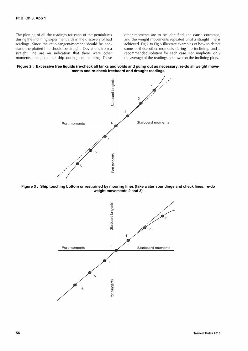
Pt B, Ch 3, App 1
56 Tasneef Rules 2016
The plotting of all the readings for each of the pendulumsduring the inclining experiment aids in the discovery of badreadings. Since the ratio tangent/moment should be con-stant, the plotted line should be straight. Deviations from astraight line are an indication that there were othermoments acting on the ship during the inclining. These
other moments are to be identified, the cause corrected,and the weight movements repeated until a straight line isachieved. Fig 2 to Fig 5 illustrate examples of how to detectsome of these other moments during the inclining, and arecommended solution for each case. For simplicity, onlythe average of the readings is shown on the inclining plots.
Figure 2 : Excessive free liquids (re-check all tanks and voids and pump out as necessary; re-do all weight move-ments and re-check freeboard and draught readings
Figure 3 : Ship touching bottom or restrained by mooring lines (take water soundings and check lines: re-do weight movements 2 and 3)
Port moments Starboard moments
Starboardtangents
Porttangents
6
5
7
4
1
3
2
Starboard moments
Porttangents
Starboardtangents
Port moments
6
5
7
4
1
3
2
Pt B, Ch 3, App 1
Tasneef Rules 2016 57
Figure 4 : Steady wind from port side came up after initial zero point taken (plot acceptable)
Figure 5 : Gusty wind from port side (re-do weight movements 1 and 5)
Starboard moments
Sta
rboard
tangents
Port moments
Port
tangents6
5
7
4
1
3
2
Starboard moments
Sta
rboard
tangents
Port moments
Port
tangents
6
5
7
4
1
3
2
Pt B, Ch 3, App 2
58 Tasneef Rules 2016
APPENDIX 2 TRIM AND STABILITY BOOKLET
1 Trim and stability booklet
1.1 Information to be included in the trim and stability booklet
1.1.1 GeneralA trim and stability booklet is a stability manual, to beapproved by the Society, which is to contain sufficient infor-mation to enable the Master to operate the ship in compli-ance with the applicable requirements contained in theRules.
The format of the stability booklet and the informationincluded vary depending on the ship type and operation.
1.1.2 List of informationThe following information is to be included in the trim andstability booklet:• a general description of the ship, including:
- the ship’s name and the Society classificationnumber
- the ship type and service notation - the class notations - the yard, the hull number and the year of delivery - the Flag, the port of registry, the international call
sign and the IMO number- the moulded dimensions- the draught corresponding to the assigned summer
load line, the draught corresponding to the assignedsummer timber load line and the draught corre-sponding to the tropical load line, if applicable
- the displacement corresponding to the above-men-tioned draughts
• clear instructions on the use of the booklet• general arrangement and capacity plans indicating the
assigned use of compartments and spaces (cargo, pas-senger, stores, accommodation, etc.)
• a sketch indicating the position of the draught marksreferred to the ship’s perpendiculars
• hydrostatic curves or tables corresponding to the designtrim, and, if significant trim angles are foreseen duringthe normal operation of the ship, curves or tables corre-sponding to such range of trim are to be introduced. Aclear reference relevant to the sea density, in t/m3, is tobe included as well as the draught measure (from keelor underkeel).
• cross curves (or tables) of stability calculated on a freetrimming basis, for the ranges of displacement and trimanticipated in normal operating conditions, with indica-tion of the volumes which have been considered in thecomputation of these curves
• tank sounding tables or curves showing capacities, cen-tres of gravity, and free surface data for each tank
• lightship data from the inclining test, as indicated inSec 1, [3.2], including lightship displacement, centre ofgravity co-ordinates, place and date of the inclining test,as well as the Society approval details specified in theinclining test report. It is suggested that a copy of theapproved test report be included.
Where the above-mentioned information is derivedfrom a sister ship, the reference to this sister ship is to beclearly indicated, and a copy of the approved incliningtest report relevant to this sister ship is to be included.
• standard loading conditions as indicated in [1.2] andexamples for developing other acceptable loading con-ditions using the information contained in the booklet
• intact stability results (total displacement and its centreof gravity co-ordinates, draughts at perpendiculars, GM,GM corrected for free surfaces effect, GZ values andcurve, criteria as indicated in Sec 2, [2] and Sec 2, [3]as well as possible additional criteria specified in Part Ewhen applicable, reporting a comparison between theactual and the required values) are to be available foreach of the above-mentioned operating conditions. Themethod and assumptions to be followed in the stabilitycurve calculation are specified in [1.3]
• information on loading restrictions (maximum allowa-ble load on double bottom, maximum specific gravityallowed in liquid cargo tanks, maximum filling level orpercentage in liquid cargo tanks) when applicable
• information about openings (location, tightness, meansof closure), pipes or other progressive flooding sources
• any other necessary guidance for the safe operation ofthe ship
• a table of contents and index for each booklet.
1.2 Loading conditions
1.2.1 General
The standard loading conditions to be included in the trimand stability booklet are:
• lightship condition
• ship in ballast in the departure condition, without cargobut with full stores and fuel
• ship in ballast in the arrival condition, without cargoand with 10% stores and fuel remaining.
Additional loading conditions are required depending onthe ship type and kind of cargo carried as specified in thefollowing paragraphs, such loading cases being consideredas a minimum requirement. Therefore, further loading casesmay be included when deemed necessary or useful.
When a tropical freeboard is to be assigned to the ship, thecorresponding loading conditions are also to be included.

Pt B, Ch 3, App 2
Tasneef Rules 2016 59
1.2.2 Ships carrying cargo on deck
In addition to the loading conditions indicated in [1.2.1] to[1.2.13], in the case of cargo carried on deck the followingcases are to be considered:
• ship in the fully loaded departure condition havingcargo homogeneously distributed in the holds and awith cargo specified in extension and mass on deck,with full stores and fuel
• ship in the fully loaded arrival condition having cargohomogeneously distributed in holds and a cargo speci-fied in extension and weight on deck, with 10% storesand fuel.
1.2.3 General cargo ships
In addition to the standard loading conditions reported in[1.2.1], at least the following loading cases are to beincluded in the trim and stability booklet:
• ship in the fully loaded departure condition, with cargohomogeneously distributed throughout all cargo spacesand with full stores and fuel
• ship in the fully loaded arrival condition with cargohomogeneously distributed throughout all cargo spacesand with 10% stores and fuel remaining.
For ships with service notation general cargo ship com-pleted by the additional feature nonhomload, at least thefollowing loading cases are also to be included in the trimand stability booklet:
• ship in the departure condition, with cargo in alternateholds, for at least three stowage factors, one of which isrelevant to the summer load waterline and with fullstores and consumables.
Where the condition with cargo in alternate holds rele-vant to the summer load waterline leads to local loadson the double bottom greater than those allowed by theSociety, it is to be replaced by the one in which eachhold is filled in order to reach the maximum loadallowed on the double bottom; in no loading case issuch value to be exceeded
• same conditions as above, but with 10% stores and con-sumables.
1.2.4 Container ships
In addition to the standard loading conditions specified in[1.2.1], for ships with the service notation container ship atleast the following loading cases are to be included in thetrim and stability booklet:
• ship with the maximum number of containers on boardhaving a homogeneous weight corresponding to thesummer load waterline when loaded with full stores andconsumables
• same loading condition as above, but with 10% storesand consumables
• ship with a number of containers having a weight corre-sponding to the maximum permissible weight for eachcontainer at the summer load waterline when loadedwith full stores and consumables
• same loading condition as above, but with 10% storesand consumables
• lightship condition with full stores and consumables
• lightship condition with 10% stores and consumables.
The two latter conditions are to be included for informationto the Master regarding the ship’s stability before loadingcommences or unloading terminates.
The vertical location of the centre of gravity for each con-tainer is generally to be taken at one half of the containerheight. Different locations of the vertical centre of gravitymay be accepted in specific cases, only if adequately docu-mented.
1.2.5 Bulk carriers, ore carriers and combination carriers
Dry cargo is intended to mean grain, as well as any othertype of solid bulk cargo.
The term grain covers wheat, maize (corn), oats, rye, barley,rice, pulses, seeds and processed forms thereof, whosebehaviour is similar to that of grain in its natural state.
The term solid bulk cargo covers any material, other thanliquid or gas, consisting of a combination of particles, gran-ules or any larger pieces of material, generally uniform incomposition, which is loaded directly into the cargo spacesof a ship without any intermediate form of containment.
In addition to the standard loading conditions defined in[1.2.1], for ships with the service notation bulk carrier ESP,ore carrier ESP and combination carrier ESP at least the fol-lowing loading cases are to be included in the trim and sta-bility booklet:
• ship in the fully loaded departure conditions at the sum-mer load waterline, with cargo homogeneously distrib-uted throughout all cargo holds and with full stores andconsumables, for at least three specific gravities, one ofwhich is relevant to the complete filling of all cargoholds
• same conditions as above, but with 10% stores and con-sumables
• ship in the departure condition, with cargo holds notentirely filled, for at least three stowage factors, one ofwhich is relevant to the summer load waterline and withfull stores and consumables
• same conditions as above, but with 10% stores and con-sumables.
For ships with one of the service notations ore carrier ESPand combination carrier ESP and for ships with the servicenotation bulk carrier ESP completed by the additional fea-ture nonhomload, at least the following loading cases arealso to be included in the trim and stability booklet:
• ship in the departure conditions, with cargo in alternateholds, for at least three stowage factors, one of which isrelevant to the summer load waterline, and with fullstores and consumables.
Where the condition with cargo in alternate holds rele-vant to the summer load waterline leads to local loadson the double bottom greater than those allowed by theSociety, it is to be replaced by the one in which eachhold is filled in order to reach the maximum load

Pt B, Ch 3, App 2
60 Tasneef Rules 2016
allowed on the double bottom; in no loading case issuch value to be exceeded.
• same conditions as above, but with 10% stores and con-sumables.
1.2.6 Oil tankers and FLS tankers
All the intended cargo loading conditions are to beincluded in the trim and stability booklet for examinationwithin the scope of Pt E, Ch 7, Sec 3, [1].
In addition to the standard loading conditions specified in[1.2.1], for ships with the service notation oil tanker ESP orFLS tanker at least the following loading cases are to beincluded in the trim and stability booklet:
• ship in the fully loaded departure condition at the sum-mer load waterline, with cargo homogeneously distrib-uted throughout all cargo tanks and with full stores andconsumables
• same condition as above, but with 10% stores and con-sumables
• ship in the departure condition loaded with a cargo hav-ing a density in order to fill all cargo tanks, with fullstores and consumables, but immersed at a draught lessthan the summer load waterline
• same condition as above, but with 10% stores and con-sumables
• ship in the fully loaded departure condition at the sum-mer load waterline, with cargo tanks not entirely filledand with full stores and consumables
• same condition as above, but with 10% stores and con-sumables
• two loading conditions corresponding to different cargosegregations in order to have slack tanks with full storesand consumables.
When it is impossible to have segregations, these condi-tions are to be replaced by loading conditions with thesame specific gravity and with slack cargo tanks.
• same loading condition as above, but with 10% storesand consumables
• For oil tankers having segregated ballast tanks as definedin Pt E, Ch 7, Sec 1, [1.3.13], the lightship conditionwith segregated ballast only is also to be included in thetrim and stability booklet for examination.
1.2.7 Chemical tankers
All the intended cargo loading conditions are to beincluded in the trim and stability booklet for examinationwithin the scope of IBC Code Ch 2, 2.9 and Ch 2, 2.8.1.6.
In addition to the standard loading conditions defined in[1.2.1], for ships with the service notation chemical tankerESP at least the following loading cases are to be includedin the trim and stability booklet:
• ship in the fully loaded departure condition, with cargohomogeneously distributed throughout all cargo tanksand with full stores and consumables
• same loading condition as above, but with 10% storesand consumables
• three loading conditions corresponding to different spe-cific gravities with cargo homogeneously distributedthroughout all cargo tanks and with full stores and con-sumables
• same loading conditions as above, but with 10% storesand consumables
• four loading conditions corresponding to different cargosegregations in order to have slack tanks with full storesand consumables. Cargo segregation is intended tomean loading conditions with liquids of different spe-cific gravities.
When it is impossible to have segregations, these condi-tions are to be replaced by loading conditions corre-sponding to different specific gravities with slack cargotanks.
• same loading conditions as above, but with 10% storesand consumables.
When it is impossible to have segregations, these condi-tions may be replaced by cases corresponding to differ-ent specific gravities with slack cargo tanks.
Possible limitations in the filling of cargo tanks due to struc-tural matters (i.e sloshing) are to be taken into account andare to be clearly indicated in the booklet.
1.2.8 Liquefied gas carriers
All the intended cargo loading conditions are to beincluded in the trim and stability booklet for examinationwithin the scope of IGC Code Ch 2, 2.9 and Ch 2, 2.8.1.6.
In addition to the standard loading conditions defined in[1.2.1], for ships with the service notation liquefied gas car-rier at least the following loading cases are to be includedin the trim and stability booklet:
• ship in the fully loaded departure condition, with cargohomogeneously distributed throughout all cargo spacesand with full stores and fuel
• ship in the fully loaded arrival condition with cargohomogeneously distributed throughout all cargo spacesand with 10% stores and fuel remaining.
1.2.9 Passenger ships
In addition to the standard loading conditions specified in[1.2.1], for ships with the service notation passenger ship atleast the following loading cases are to be included in thetrim and stability booklet:
• ship in the fully loaded departure condition at the sum-mer load line with cargo, with full stores and fuel andwith the full number of passengers with their luggage;
• ship in the fully loaded arrival condition, with cargo,with the full number of passengers and their luggage butwith only 10% stores and fuel remaining;
• ship without cargo, but with full stores and fuel and thefull number of passengers and their luggage;
• ship in the same condition as above, but with only 10%stores and fuel remaining.
Pt B, Ch 3, App 2
Tasneef Rules 2016 61
1.2.10 Dredgers
For ships with one of the service notations dredger, hopperdredger, hopper unit, split hopper dredger and split hop-per unit, the following loading conditions are to be consid-ered:
a) Dredging unit in lightship condition
b) Dredging unit in ballast in the departure condition with-out dredged materials and with the dredging devicessuitably lashed, with full stores and fuel
c) Dredging unit in ballast in the arrival condition, withoutdredged materials and with the dredging devices suita-bly lashed, with 10% stores and fuel remaining
d) Dredging unit in working condition with full stores andfuel, wells with homogeneous full loading of dredgedspoil up to the overflow pipes or, where the latter arenot fitted, up to the top of the hatchway and withdraught corresponding to the summer freeboard
e) Dredging unit as per item d) but with only 10% of storesand fuel
f) Dredging unit in working condition with full stores andfuel, with wells with homogeneous partial loading ofdredged spoil having mass density equal to 2,2 t/m3 andwith draught corresponding to the summer freeboard
g) Dredging unit as per item f) but with only 10% of storesand fuel.
1.2.11 Tugs and fire-fighting ships
In addition to the standard loading conditions defined in[1.2.1], for ships with one of the service notations tug andfire fighting ship at least the following loading cases are tobe included in the trim and stability booklet:
• ship in the departure condition at the waterline corre-sponding to the maximum assigned immersion, with fullstores, provisions and consumables
• same conditions as above, but with 10% stores and con-sumables.
1.2.12 Supply vessels
In addition to the standard loading conditions specified in[1.2.1], for ships with the service notation supply vessel atleast the following loading cases are to be included in thetrim and stability booklet:
• ship in the fully loaded departure condition havingunder deck cargo, if any, and cargo specified by posi-tion and weight on deck, with full stores and fuel, corre-sponding to the worst service condition in which all therelevant stability criteria are met
• ship in the fully loaded arrival condition with cargo asspecified above, but with 10 per cent stores and fuel.
1.2.13 Fishing vessels
In addition to the standard loading conditions defined in[1.2.1], for ships with the service notation fishing vessel at
least the following loading cases are to be included in thetrim and stability booklet:
• departure conditions for the fishing grounds with fullfuel stores, ice, fishing gear, etc.
• departure from the fishing grounds with full catch
• arrival at home port with 10% stores, fuel, etc. remain-ing and full catch
• arrival at home port with 10% stores, fuel, etc. and aminimum catch, which is normally to be 20% of the fullcatch but may be up to 40% provided the Society is sat-isfied that operating patterns justify such a value.
1.3 Stability curve calculation
1.3.1 General
Hydrostatic and stability curves are normally prepared forthe trim range of operating loading conditions taking intoaccount the change in trim due to heel (free trim hydro-static calculation).
The calculations are to take into account the volume to theupper surface of the deck sheathing.
1.3.2 Superstructures, deckhouses, etc. which may be taken into account
Enclosed superstructures complying with Ch 1, Sec 2,[3.10] may be taken into account.
Additional tiers of similarly enclosed superstructures mayalso be taken into account, except for ships of length lessthan 20 m, for which only the first tier of enclosed super-structures may be taken into account and, in the event ofdoors on both sides of a deckhouse, access from the top isnot required.
As guidance, windows (pane and frame) that are consid-ered without deadlights in additional tiers above the secondtier if considered buoyant are to be designed with strengthto sustain a safety margin of at least 30% with regard to therequired strength of the surrounding structure.
Deckhouses on the freeboard deck may be taken intoaccount, provided that they comply with the conditions forenclosed superstructures laid down in Ch 1, Sec 2, [3.12].
Where deckhouses comply with the above conditions,except that no additional exit is provided to a deck above,such deckhouses are not to be taken into account; however,any deck openings inside such deckhouses are to be consid-ered as closed even where no means of closure are pro-vided.
Deckhouses, the doors of which do not comply with therequirements of Ch 9, Sec 4, [1.5.4], are not to be takeninto account; however, any deck openings inside the deck-house are regarded as closed where their means of closurecomply with the requirements of Ch 9, Sec 7, [7].
Deckhouses on decks above the freeboard deck are not tobe taken into account, but openings within them may beregarded as closed.

Pt B, Ch 3, App 2
62 Tasneef Rules 2016
Superstructures and deckhouses not regarded as enclosedmay, however, be taken into account in stability calculationsup to the angle at which their openings are flooded (at thisangle, the static stability curve is to show one or more steps,and in subsequent computations the flooded space are tobe considered non-existent).
Trunks may be taken into account. Hatchways may also betaken into account having regard to the effectiveness oftheir closures.
1.3.3 Angle of floodingIn cases where the ship would sink due to flooding throughany openings, the stability curve is to be cut short at the cor-
responding angle of flooding and the ship is to be consid-ered to have entirely lost its stability.Small openings such as those for passing wires or chains,tackle and anchors, and also holes of scuppers, dischargeand sanitary pipes are not to be considered as open if theysubmerge at an angle of inclination more than 30°. If theysubmerge at an angle of 30° or less, these openings are tobe assumed open if the Society considers this to be a sourceof significant progressive flooding; therefore such openingsare to be considered on a case by case basis.

Tasneef Rules 2016 63
Part BHull and Stability
Chapter 4
STRUCTURE DESIGN PRINCIPLES
SECTION 1 MATERIALS
SECTION 2 NET SCANTLING APPROACH
SECTION 3 STRENGTH PRINCIPLES
SECTION 4 BOTTOM STRUCTURE
SECTION 5 SIDE STRUCTURE
SECTION 6 DECK STRUCTURE
SECTION 7 BULKHEAD STRUCTURE


Pt B, Ch 4, Sec 1
Tasneef Rules 2016 65
SECTION 1 MATERIALS
1 General
1.1 Characteristics of materials
1.1.1 The characteristics of the materials to be used in theconstruction of ships are to comply with the applicablerequirements of Part D.
1.1.2 Materials with different characteristics may beaccepted, provided their specification (manufacture, chemi-cal composition, mechanical properties, welding, etc.) issubmitted to the Society for approval.
1.2 Testing of materials
1.2.1 Materials are to be tested in compliance with theapplicable requirements of Part D.
1.3 Manufacturing processes
1.3.1 The requirements of this Section presume that weld-ing and other cold or hot manufacturing processes are car-ried out in compliance with current sound working practiceand the applicable requirements of Part D. In particular:• parent material and welding processes are to be
approved within the limits stated for the specified typeof material for which they are intended
• specific preheating may be required before welding• welding or other cold or hot manufacturing processes
may need to be followed by an adequate heat treatment.
2 Steels for hull structure
2.1 Application
2.1.1 Tab 1 gives the mechanical characteristics of steelscurrently used in the construction of ships.
2.1.2 Higher strength steels other than those indicated inTab 1 are considered by the Society on a case by case basis.
2.1.3 When steels with a minimum guaranteed yield stressReH other than 235 N/mm2 are used on a ship, hull scant-lings are to be determined by taking into account the mate-rial factor k defined in [2.3].
2.1.4 Characteristics of steels with specified through thick-ness properties are given in Pt D, Ch 2, Sec 1, [9].
2.2 Information to be kept on board
2.2.1 A plan is to be kept on board indicating the steeltypes and grades adopted for the hull structures. Wheresteels other than those indicated in Tab 1 are used, theirmechanical and chemical properties, as well as any work-
manship requirements or recommendations, are to be avail-able on board together with the above plan.
2.2.2 It is also recommended that a plan is kept on boardindicating the hull structures built in normal strength steelof grades D or E.
Table 1 : Mechanical properties of hull steels
2.3 Material factor k
2.3.1 GeneralUnless otherwise specified, the material factor k has the val-ues defined in Tab 2, as a function of the minimum guaran-teed yield stress ReH.
For intermediate values of ReH , k may be obtained by linearinterpolation.
Steels with a yield stress lower than 235 N/mm2 or greaterthan 390 N/mm2 are considered by the Society on a case bycase basis.
Table 2 : Material factor k
2.4 Grades of steel
2.4.1 Materials in the various strength members are not tobe of lower grade than those corresponding to the material
Steel gradesMinimum yield
stress ReH, in N/mm2
Ultimate minimum tensile strength Rm,
in N/mm2
A-B-D-Et ≤ 100mm
235 400 - 520
AH32-DH32-EH32t ≤ 100mmFH32t ≤ 50mm
315 440 - 590
AH36-DH36-EH36t ≤ 100mmFH36t ≤ 50mm
355 490 - 620
AH40-DH40-EH40 FH40t ≤ 50mm
390 510 - 650
Note 1:Reference in Part D: Pt D, Ch 2, Sec 1, [2]
ReH , in N/mm2 k
235 1
315 0,78
355 0,72
390 0,68

Pt B, Ch 4, Sec 1
66 Tasneef Rules 2016
classes and grades specified in Tab 3 to Tab 6. Generalrequirements are given in Tab 3, while additional minimumrequirements for ships with length exceeding 150 m and250 m are given in Tab 4 and Tab 5.
2.4.2 The material grade requirements for hull members ofeach class depending on the thickness are defined in Tab 6.
Table 3 : Material Classes and Grades for ships in general
Structural member category Material class/grade
SECONDARY:• Longitudinal bulkhead strakes, other than that belonging to the Primary category• Deck plating exposed to weather, other than that belonging to the Primary or Special category• Side plating
• Class I within 0,4L amidships
• Grade A/AH outside 0,4L amidships
PRIMARY:• Bottom plating, including keel plate• Strength deck plating, excluding that belonging to the Special category• Continuous longitudinal plating of strength members above strength deck, excluding hatch coam-
ings• Uppermost strake in longitudinal bulkhead• Vertical strake (hatch side girder) and uppermost sloped strake in top wing tank
• Class II within 0,4L amidships
• Grade A/AH outside 0,4L amidships
SPECIAL:• Sheerstrake at strength deck (1)• Stringer plate in strength deck (1)• Deck strake at longitudinal bulkhead, excluding deck plating in way of inner-skin bulkhead of dou-
ble hull ships (1)
• Class III within 0,4L amidships
• Class II outside 0,4L amidships
• Class I outside 0,6L amidships
• Strength deck plating at outboard corners of cargo hatch openings in container carriers and other ships with similar hatch opening configurations
• Class III within 0,4L amidships
• Class II outside 0,4L amidships
• Class I outside 0,6L amidships
• Min. Class III within cargo region
• Strength deck plating at corners of cargo hatch openings in bulk carriers, ore carriers, combination carriers and other ships with similar hatch opening configurations
• Class III within 0,6L amidships
• Class II within rest of cargo region
• Bilge strake in ships with double bottom over the full breadth and length less than 150 m (1) • Class II within 0,6L amidships
• Class I outside 0,6L amidships
• Bilge strake in other ships (1) • Class III within 0,4L amidships
• Class II outside 0,4L amidships
• Class I outside 0,6L amidships
• Longitudinal hatch coamings of length greater than 0,15L including coaming top plate and flange• End brackets and deck house transition of longitudinal cargo hatch coamings
• Class III within 0,4L amidships
• Class II outside 0,4L amidships
• Class I outside 0,6L amidships
• Not to be less than Grade D/DH
(1) Single strakes required to be of Class III within 0,4L amidships are to have breadths not less than 800+5L (mm), but need not be greater than 1800 (mm), unless limited by the geometry of the ship's design.
Pt B, Ch 4, Sec 1
Tasneef Rules 2016 67
Table 4 : Minimum Material Grades for ships with length exceeding 150 m and single strength deck
Table 5 : Minimum Material Grades for ships with length exceeding 250 m
Table 6 : Material grade requirementsfor classes I, II and III
2.4.3 For strength members not mentioned in Tab 3 toTab 5, grade A/AH may generally be used.
2.4.4 The steel grade is to correspond to the as-built platethickness and material class.
2.4.5 Steel grades of plates or sections of gross thicknessgreater than the limiting thicknesses in Tab 1 are consideredby the Society on a case by case basis.
2.4.6 In specific cases, such as [2.4.7], with regard tostress distribution along the hull girder, the classes requiredwithin 0,4L amidships may be extended beyond that zone,on a case by case basis.
2.4.7 The material classes required for the strength deckplating, the sheerstrake and the upper strake of longitudinalbulkheads within 0,4L amidships are to be maintained for
an adequate length across the poop front and at the ends ofthe bridge, where fitted.
2.4.8 Rolled products used for welded attachments on hullplating, such as gutter bars and bilge keels, are to be of thesame grade as that used for the hull plating in way.
Where it is necessary to weld attachments to the sheerstrakeor stringer plate, attention is to be given to the appropriatechoice of material and design, the workmanship and weld-ing and the absence of prejudicial undercuts and notches,with particular regard to any free edges of the material.
2.4.9 In the case of grade D plates with a nominal thick-ness equal to or greater than 36 mm, or in the case of gradeDH plates with a nominal thickness equal to or greater than31 mm, the Society may, on a case by case basis, requirethe impact test to be carried out on each original “rolledunit”, where the above plates:
• either are to be placed in positions where high localstresses may occur, for instance at breaks of poop andbridge, or in way of large openings on the strength deckand on the bottom, including relevant doublings, or
• are to be subjected to considerable cold working.
2.4.10 In the case of full penetration welded joints locatedin positions where high local stresses may occur perpendic-ular to the continuous plating, the Society may, on a case bycase basis, require the use of rolled products having ade-quate ductility properties in the through thickness direction,such as to prevent the risk of lamellar tearing (Z type steel,see Part D).
2.4.11 In highly stressed areas, the Society may requirethat plates of gross thickness greater than 20 mm are ofgrade D/DH or E/EH.
2.4.12 For certain uses, grade B steel with controlledtoughness at 0°C may be required for plates of gross thick-ness less than 25 mm.
Structural member category Material grade
• Longitudinal plating of strength deck where contributing to the longitudinal strength
• Continuous longitudinal plating of strength members above strength deck
Grade B/AH within 0,4L amidships
Single side strakes for ships without inner continuous longitudinal bulkhead(s) between bottom and the strength deck
Grade B/AH within cargo region
Structural member category Material grade
Sheerstrake at strength deck (1) Grade E/EH within 0,4L amidships
Stringer plate in strength deck (1) Grade E/EH within 0,4L amidships
Bilge strake (1) Grade D/DH within 0,4L amidships
(1) Single strakes required to be of Grade E/EH and within 0,4L amidships are to have breadths not less than 800+5L (mm), but need not be greater than 1800 (mm), unless limited by the geometry of the ship's design.
Class I II III
Gross thick-ness, in mm
NSS HSS NSS HSS NSS HSS
t ≤ 15 A AH A AH A AH
15 < t ≤ 20 A AH A AH B AH
20 < t ≤ 25 A AH B AH D DH
25 < t ≤ 30 A AH D DH D DH
30 < t ≤ 35 B AH D DH E EH
35 < t ≤ 40 B AH D DH E EH
40 < t ≤ 50 D DH E EH E EH
Note 1:“NSS” and “HSS” mean, respectively: “Normal Strength Steel” and “Higher Strength Steel”.

Pt B, Ch 4, Sec 1
68 Tasneef Rules 2016
2.4.13 Plating materials for sternframes, rudders, rudderhorns and shaft brackets are, in general, not to be of lowergrades than corresponding to Class II. For rudder and rudderbody plates subjected to stress concentrations (e.g. in wayof lower support of semi-spade rudders or at upper part ofspade rudders), Class III is to be applied.
2.5 Grades of steel for structures exposed to low air temperatures
2.5.1 For ships intended to operate in areas with low airtemperatures (-20°C or below), e.g. regular service duringwinter seasons to Arctic or Antarctic waters, the materials inexposed structures are to be selected based on the designtemperature tD, to be taken as defined in [2.5.2].
2.5.2 The design temperature tD is to be taken as the low-est mean daily average air temperature in the area of opera-tion, where:
Mean : Statistical mean over observation period (at least20 years)
Average : Average during one day and night
Lowest : Lowest during one year
Fig 1 illustrates the temperature definition.
For seasonally restricted service, the lowest value within theperiod of operation applies.
Figure 1 : Commonly used definitions of temperatures
Table 7 : Application of material classes and grades for structures exposed to low air temperatures
Mean daily maximum temperature
Mean daily average temperature
tD = design temperature
Mean daily minimum temperature
Structural member categoryMaterial class
Within 0,4L amidships Outside 0,4L amidships
SECONDARY:Deck plating exposed to weather (in general)Side plating above TB (1)Transverse bulkheads above TB (1)
I I
PRIMARY:Strength deck plating (2)Continuous longitudinal members above strength deck (excluding longitudi-nal hatch coamings of ships equal to or greater than 90 m in length)Longitudinal bulkhead above TB (1)Topside tank bulkhead above TB (1)
II I
SPECIAL:Sheer strake at strength deck (3)Stringer plate in strength deck (3)Deck strake at longitudinal bulkhead (4)Continuous longitudinal hatch coamings of ships equal to or greater than 90 m in length (5)
III II
(1) TB is the draught in light ballast condition, defined in Ch 5, Sec 1, [2.4.3].(2) Plating at corners of large hatch openings to be considered on a case by case basis.
Class III or grade E/EH to be applied in positions where high local stresses may occur.(3) To be not less than grade E/EH within 0,4 L amidships in ships with length exceeding 250 m.(4) In ships with breadth exceeding 70 metres at least three deck strakes to be class III.(5) To be not less than grade D/DH.Note 1:Plating materials for sternframes, rudder horns, rudders and shaft brackets are to be of grades not lower than those corre-sponding to the material classes in [2.4].

Pt B, Ch 4, Sec 1
Tasneef Rules 2016 69
2.5.3 For the purpose of the selection of steel grades to beused for the structural members above the lowest ballastwaterline and exposed to air, the latter are divided into cat-egories (SECONDARY, PRIMARY and SPECIAL), as indi-cated in Tab 7.Tab 7 also specifies the classes (I, II and III) of the materialsto be used for the various categories of structural members.
For non-exposed structures and structures below the lowestballast waterline, see [2.4].
2.5.4 Materials may not be of a lower grade than that indi-cated in Tab 8 to Tab 10 depending on the material class,structural member gross thickness and design temperaturetD.
For design temperatures tD < -55°C, materials will be spe-cially considered by the Society on a case by case basis.
2.5.5 Single strakes required to be of class III or of gradeE/EH of FH are to have breadths not less than (800+5L) mm,but not necessarily greater than 1800 mm.
2.6 Grades of steel within refrigerated spaces
2.6.1 For structural members within or adjacent to refriger-ated spaces, when the design temperatures is below 0°C,the materials are to be of grade not lower than those indi-cated in Tab 11, depending on the design temperature, thestructural member gross thickness and its category (asdefined in Tab 3).
2.6.2 Unless a temperature gradient calculation is carriedout to assess the design temperature and the steel grade inthe structural members of the refrigerated spaces, the tem-peratures to be assumed are specified below:
• temperature of the space on the uninsulated side, forplating insulated on one side only, either with uninsu-lated stiffening members (i.e. fitted on the uninsulatedside of plating) or with insulated stiffening members (i.e.fitted on the insulated side of plating)
• mean value of temperatures in the adjacent spaces, forplating insulated on both sides, with insulated stiffeningmembers, when the temperature difference between theadjacent spaces is generally not greater than 10 °C(when the temperature difference between the adjacentspaces is greater than 10°C, the temperature value isestablished by the Society on a case by case basis)
• in the case of non-refrigerated spaces adjacent to refrig-erated spaces, the temperature in the non-refrigeratedspaces is to be conventionally taken equal to 0°C.
2.6.3 Situations other than those mentioned in [2.6.1] and[2.6.2] or special arrangements will be considered by theSociety on a case by case basis.
2.6.4 Irrespective of the provisions of [2.6.1], [2.6.2] andTab 11, steel having grades lower than those required in[2.4], Tab 3 to Tab 6, in relation to the class and gross thick-ness of the structural member considered, may not be used.
Table 8 : Material grade requirements for class I at low temperatures
Gross thickness, in mm
-20°C / -25°C -26°C / -35°C -36°C / -45°C -46°C / -55°C
NSS HSS NSS HSS NSS HSS NSS HSS
t ≤ 10 A AH B AH D DH D DH
10 < t ≤ 15 B AH D DH D DH D DH
15 < t ≤ 20 B AH D DH D DH E EH
20 < t ≤ 25 D DH D DH D DH E EH
25 < t ≤ 30 D DH D DH E EH E EH
30 < t ≤ 35 D DH D DH E EH E EH
35 < t ≤ 45 D DH E EH E EH φ FH
45 < t ≤ 50 E EH E EH φ FH φ FH
Note 1:“NSS” and “HSS” mean, respectively, “Normal Strength Steel” and “Higher Strength Steel”.Note 2:“φ” = not applicable.

Pt B, Ch 4, Sec 1
70 Tasneef Rules 2016
Table 9 : Material grade requirements for class II at low temperatures
Table 10 : Material grade requirements for class III at low temperatures
Table 11 : Material grade requirements for members within or adjacent to refrigerated spaces
3 Steels for forging and casting
3.1 General
3.1.1 Mechanical and chemical properties of steels forforging and casting to be used for structural members are tocomply with the applicable requirements of Part D.
3.1.2 Steels of structural members intended to be weldedare to have mechanical and chemical properties deemedappropriate for this purpose by the Society on a case bycase basis.
3.1.3 The steels used are to be tested in accordance withthe applicable requirements of Part D.
3.2 Steels for forging
3.2.1 For the purpose of testing, which is to be carried outin accordance with the applicable requirements of Part D,the above steels for forging are assigned to class 1 (see Pt D,Ch 2, Sec 3, [1.2]).
3.2.2 Rolled bars may be accepted in lieu of forged prod-ucts, after consideration by the Society on a case by casebasis.
In such case, compliance with the requirements of Pt D,Ch 2, Sec 1, relevant to the quality and testing of rolledparts accepted in lieu of forged parts, may be required.
Gross thickness, in mm
-20°C / -25°C -26°C / -35°C -36°C / -45°C -46°C / -55°C
NSS HSS NSS HSS NSS HSS NSS HSS
t ≤ 10 B AH D DH D DH E EH
10 < t ≤ 20 D DH D DH E EH E EH
20 < t ≤ 30 D DH E EH E EH φ FH
30 < t ≤ 40 E EH E EH φ FH φ FH
40 < t ≤ 45 E EH φ FH φ FH φ φ
45 < t ≤ 50 E EH φ FH φ FH φ φ
Note 1:“NSS” and “HSS” mean, respectively, “Normal Strength Steel” and “Higher Strength Steel”.Note 2:“φ” = not applicable.
Gross thickness, in mm
-20°C / -25°C -26°C / -35°C -36°C / -45°C -46°C / -55°C
NSS HSS NSS HSS NSS HSS NSS HSS
t ≤ 10 D DH D DH E EH E EH
10 < t ≤ 20 D DH E EH E EH φ FH
20 < t ≤ 25 E EH E EH E FH φ FH
25 < t ≤ 30 E EH E EH φ FH φ FH
30 < t ≤ 35 E EH φ FH φ FH φ φ
35 < t ≤ 40 E EH φ FH φ FH φ φ
40 < t ≤ 50 φ FH φ FH φ φ φ φ
Note 1:“NSS” and “HSS” mean, respectively, “Normal Strength Steel” and “Higher Strength Steel”.Note 2:“φ” = not applicable.
Design tem-perature, in
°C
Gross thickness,
in mm
Structural member category
SecondaryPrimary or
Special
t ≤ 20 B / AH B / AH
-10 ≤ tD < 0 20 < t ≤ 25 B / AH D / DH
t > 25 D / DH E / EH
t ≤ 15 B / AH D / DH
-25 ≤ tD < -10 15 < t ≤ 25 D / DH E / EH
t > 25 E / EH E / EH
-40 ≤ tD < -25 t ≤ 25 D / DH E / EH
t > 25 E / EH E / EH

Pt B, Ch 4, Sec 1
Tasneef Rules 2016 71
3.3 Steels for casting
3.3.1 Cast parts intended for stems, sternframes, rudders,parts of steering gear and deck machinery in general may bemade of C and C-Mn weldable steels of quality 1, havingtensile strength Rm = 400 N/mm2 or 440 N/mm2, in accord-ance with the applicable requirements of Pt D, Ch 2, Sec 4.
Items which may be subjected to high stresses may berequired to be of quality 2 steels of the above types.
3.3.2 For the purpose of testing, which is to be carried outin accordance with Pt D, Ch 2, Sec 4, [1.11], the abovesteels for casting are assigned to class 1 irrespective of theirquality.
3.3.3 The welding of cast parts to main plating contribut-ing to hull strength members is considered by the Societyon a case by case basis.
The Society may require additional properties and tests forsuch casting, in particular impact properties which areappropriate to those of the steel plating on which the castparts are to be welded and non-destructive examinations.
3.3.4 Heavily stressed cast parts of steering gear, particu-larly those intended to form a welded assembly and tillersor rotors mounted without key, are to be subjected to non-destructive examination to check their internal structure.
4 Aluminium alloy structures
4.1 General
4.1.1 The characteristics of aluminium alloys are to com-ply with the requirements of Pt D, Ch 3, Sec 2.
Series 5000 aluminium-magnesium alloys or series 6000 aluminium-magnesium-silicon alloys are generally to be used (see Pt D, Ch 3, Sec 2, [2]).
4.1.2 In the case of structures subjected to low servicetemperatures or intended for other specific applications, thealloys to be employed are defined in each case by the Soci-ety, which states the acceptability requirements and condi-tions.
4.2 Extruded plating
4.2.1 Extrusions with built-in plating and stiffeners,referred to as extruded plating, may be used.
4.2.2 In general, the application is limited to decks, bulk-heads, superstructures and deckhouses. Other uses may bepermitted by the Society on a case by case basis.
4.2.3 Extruded plating is preferably to be oriented so thatthe stiffeners are parallel to the direction of main stresses.
4.2.4 Connections between extruded plating and primarymembers are to be given special attention.
4.3 Influence of welding on mechanical characteristics
4.3.1 Welding heat input lowers locally the mechanicalstrength of aluminium alloys hardened by work hardening(series 5000 other than condition 0 or H111) or by heattreatment (series 6000).
4.3.2 Consequently, where necessary, a drop in themechanical characteristics of welded structures with respectto those of the parent material is to be considered in theheat-affected zone.
The heat-affected zone may be taken to extend 25 mm oneach side of the weld axis.
4.3.3 Aluminium alloys of series 5000 in 0 condition(annealed) or in H111 condition (annealed flattened) arenot subject to a drop in mechanical strength in the weldedareas.
4.3.4 Aluminium alloys of series 5000 other than condi-tion 0 or H111 are subject to a drop in mechanical strengthin the welded areas.
The mechanical characteristics to consider are normallythose of condition 0 or H111.
Higher mechanical characteristics may be taken intoaccount, provided they are duly justified.
4.3.5 Aluminium alloys of series 6000 are subject to adrop in mechanical strength in the vicinity of the weldedareas.
The mechanical characteristics to be considered are nor-mally indicated by the supplier.
4.4 Material factor k
4.4.1 The material factor k for aluminium alloys is to beobtained from the following formula:
where:
η : Joint coefficient for the welded assembly, corre-sponding to the aluminium alloy considered,given in Tab 12
Rp0,2 : Minimum guaranteed yield stress, in N/mm2, ofthe parent material in delivery condition.
4.4.2 In the case of welding of two different aluminiumalloys, the material factor k to be considered for the scant-lings is the greater material factor of the aluminium alloys ofthe assembly.
5 Other materials and products
5.1 General
5.1.1 Other materials and products such as parts made ofiron castings, where allowed, products made of copper andcopper alloys, rivets, anchors, chain cables, cranes, masts,derrick posts, derricks, accessories and wire ropes are gen-erally to comply with the applicable requirements of Part D.
k 235ηRp0 2,
---------------=

Pt B, Ch 4, Sec 1
72 Tasneef Rules 2016
5.1.2 The use of plastics or other special materials not cov-ered by these Rules is to be considered by the Society on acase by case basis. In such cases, the Society states therequirements for the acceptance of the materials con-cerned.
5.1.3 Materials used in welding processes are to complywith the applicable requirements of Part D.
5.2 Iron cast parts
5.2.1 As a rule, the use of grey iron, malleable iron orspheroidal graphite iron cast parts with combined fer-ritic/perlitic structure is allowed only to manufacture lowstressed elements of secondary importance.
5.2.2 Ordinary iron cast parts may not be used for win-dows or sidescuttles; the use of high grade iron cast parts ofa suitable type will be considered by the Society on a caseby case basis.
Table 12 : Joint coefficient for aluminium alloys
Table 13 : Aluminium alloysMetallurgical efficiency coefficient β
Aluminium alloy η
Alloys without work-hardening treatment (series 5000 in annealed condition 0 or annealed flattened condition H111)
1
Alloys hardened by work hardening (series 5000 other than condition 0 or H111)
R’p0,2/Rp0,2
Alloys hardened by heat treatment (series 6000) (1)
R’p0,2/Rp0,2
(1) When no information is available, coefficient η is to be taken equal to the metallurgical efficiency coefficient β defined in Tab 13.
Note 1:R’p0,2 : Minimum guaranteed yield stress, in N/mm2, of
material in welded condition (see [4.3]).
Aluminium alloyTemper con-
dition
Gross thickness,
in mmβ
6005 A(Open sections)
T5 or T6 t ≤ 6 0,45
t > 6 0,40
6005 A(Closed sections)
T5 or T6 All 0,50
6061 (Sections) T6 All 0,53
6082 (Sections) T6 All 0,45
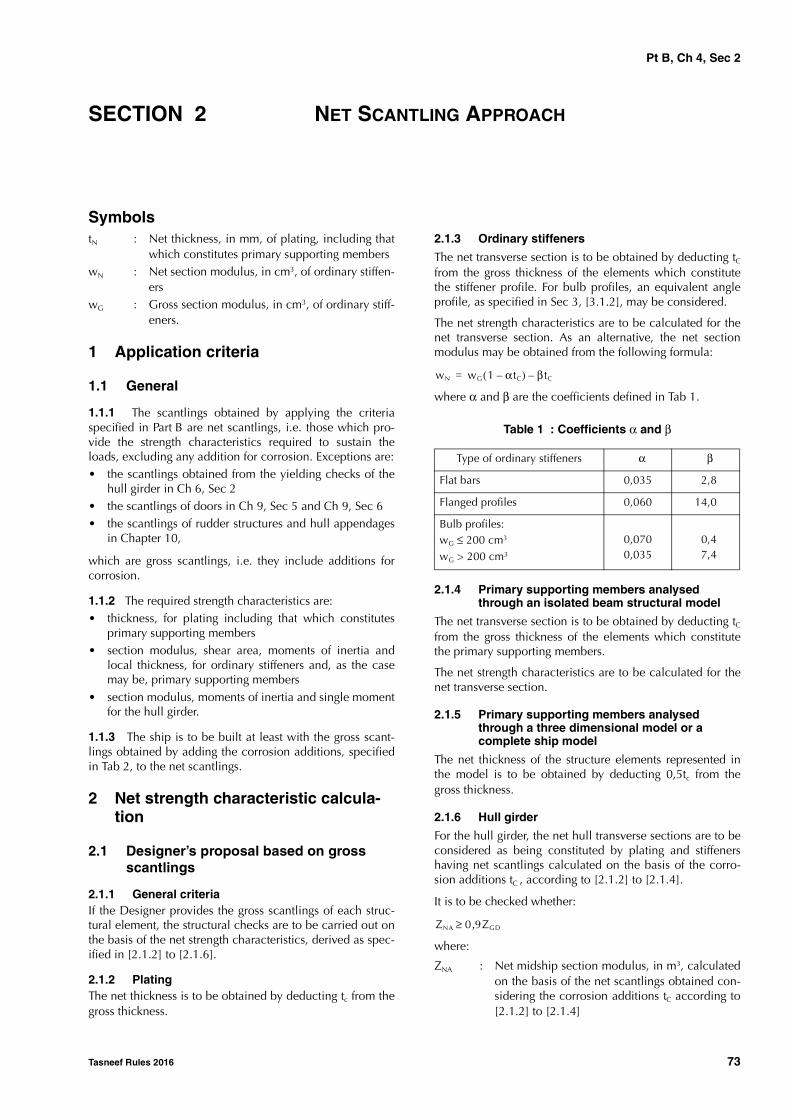
Pt B, Ch 4, Sec 2
Tasneef Rules 2016 73
SECTION 2 NET SCANTLING APPROACH
SymbolstN : Net thickness, in mm, of plating, including that
which constitutes primary supporting memberswN : Net section modulus, in cm3, of ordinary stiffen-
erswG : Gross section modulus, in cm3, of ordinary stiff-
eners.
1 Application criteria
1.1 General
1.1.1 The scantlings obtained by applying the criteriaspecified in Part B are net scantlings, i.e. those which pro-vide the strength characteristics required to sustain theloads, excluding any addition for corrosion. Exceptions are:• the scantlings obtained from the yielding checks of the
hull girder in Ch 6, Sec 2• the scantlings of doors in Ch 9, Sec 5 and Ch 9, Sec 6 • the scantlings of rudder structures and hull appendages
in Chapter 10,
which are gross scantlings, i.e. they include additions forcorrosion.
1.1.2 The required strength characteristics are:• thickness, for plating including that which constitutes
primary supporting members • section modulus, shear area, moments of inertia and
local thickness, for ordinary stiffeners and, as the casemay be, primary supporting members
• section modulus, moments of inertia and single momentfor the hull girder.
1.1.3 The ship is to be built at least with the gross scant-lings obtained by adding the corrosion additions, specifiedin Tab 2, to the net scantlings.
2 Net strength characteristic calcula-tion
2.1 Designer’s proposal based on gross scantlings
2.1.1 General criteriaIf the Designer provides the gross scantlings of each struc-tural element, the structural checks are to be carried out onthe basis of the net strength characteristics, derived as spec-ified in [2.1.2] to [2.1.6].
2.1.2 Plating The net thickness is to be obtained by deducting tc from thegross thickness.
2.1.3 Ordinary stiffeners
The net transverse section is to be obtained by deducting tCfrom the gross thickness of the elements which constitutethe stiffener profile. For bulb profiles, an equivalent angleprofile, as specified in Sec 3, [3.1.2], may be considered.
The net strength characteristics are to be calculated for thenet transverse section. As an alternative, the net sectionmodulus may be obtained from the following formula:
where α and β are the coefficients defined in Tab 1.
Table 1 : Coefficients α and β
2.1.4 Primary supporting members analysed through an isolated beam structural model
The net transverse section is to be obtained by deducting tCfrom the gross thickness of the elements which constitutethe primary supporting members.
The net strength characteristics are to be calculated for thenet transverse section.
2.1.5 Primary supporting members analysed through a three dimensional model or a complete ship model
The net thickness of the structure elements represented inthe model is to be obtained by deducting 0,5tc from thegross thickness.
2.1.6 Hull girder
For the hull girder, the net hull transverse sections are to beconsidered as being constituted by plating and stiffenershaving net scantlings calculated on the basis of the corro-sion additions tC , according to [2.1.2] to [2.1.4].
It is to be checked whether:
where:
ZNA : Net midship section modulus, in m3, calculatedon the basis of the net scantlings obtained con-sidering the corrosion additions tC according to[2.1.2] to [2.1.4]
Type of ordinary stiffeners α β
Flat bars 0,035 2,8
Flanged profiles 0,060 14,0
Bulb profiles:wG ≤ 200 cm3
wG > 200 cm3
0,0700,035
0,4 7,4
wN wG 1 α tC–( ) β tC–=
ZNA 0 9ZGD,≥
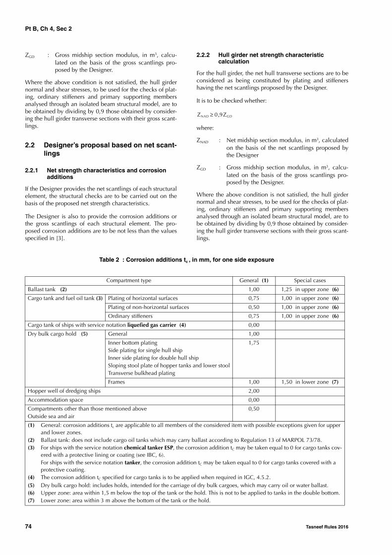
Pt B, Ch 4, Sec 2
74 Tasneef Rules 2016
ZGD : Gross midship section modulus, in m3, calcu-lated on the basis of the gross scantlings pro-posed by the Designer.
Where the above condition is not satisfied, the hull girdernormal and shear stresses, to be used for the checks of plat-ing, ordinary stiffeners and primary supporting membersanalysed through an isolated beam structural model, are tobe obtained by dividing by 0,9 those obtained by consider-ing the hull girder transverse sections with their gross scant-lings.
2.2 Designer’s proposal based on net scant-lings
2.2.1 Net strength characteristics and corrosion additions
If the Designer provides the net scantlings of each structuralelement, the structural checks are to be carried out on thebasis of the proposed net strength characteristics.
The Designer is also to provide the corrosion additions orthe gross scantlings of each structural element. The pro-posed corrosion additions are to be not less than the valuesspecified in [3].
2.2.2 Hull girder net strength characteristic calculation
For the hull girder, the net hull transverse sections are to beconsidered as being constituted by plating and stiffenershaving the net scantlings proposed by the Designer.
It is to be checked whether:
where:
ZNAD : Net midship section modulus, in m3, calculatedon the basis of the net scantlings proposed bythe Designer
ZGD : Gross midship section modulus, in m3, calcu-lated on the basis of the gross scantlings pro-posed by the Designer.
Where the above condition is not satisfied, the hull girdernormal and shear stresses, to be used for the checks of plat-ing, ordinary stiffeners and primary supporting membersanalysed through an isolated beam structural model, are tobe obtained by dividing by 0,9 those obtained by consider-ing the hull girder transverse sections with their gross scant-lings.
Table 2 : Corrosion additions tc , in mm, for one side exposure
ZNAD 0 9ZGD,≥
Compartment type General (1) Special cases
Ballast tank (2) 1,00 1,25 in upper zone (6)
Cargo tank and fuel oil tank (3) Plating of horizontal surfaces 0,75 1,00 in upper zone (6)
Plating of non-horizontal surfaces 0,50 1,00 in upper zone (6)
Ordinary stiffeners 0,75 1,00 in upper zone (6)
Cargo tank of ships with service notation liquefied gas carrier (4) 0,00
Dry bulk cargo hold (5) General 1,00
Inner bottom platingSide plating for single hull shipInner side plating for double hull shipSloping stool plate of hopper tanks and lower stoolTransverse bulkhead plating
1,75
Frames 1,00 1,50 in lower zone (7)
Hopper well of dredging ships 2,00
Accommodation space 0,00
Compartments other than those mentioned aboveOutside sea and air
0,50
(1) General: corrosion additions tc are applicable to all members of the considered item with possible exceptions given for upper and lower zones.
(2) Ballast tank: does not include cargo oil tanks which may carry ballast according to Regulation 13 of MARPOL 73/78.(3) For ships with the service notation chemical tanker ESP, the corrosion addition tC may be taken equal to 0 for cargo tanks cov-
ered with a protective lining or coating (see IBC, 6).For ships with the service notation tanker, the corrosion addition tC may be taken equal to 0 for cargo tanks covered with a protective coating.
(4) The corrosion addition tC specified for cargo tanks is to be applied when required in IGC, 4.5.2.(5) Dry bulk cargo hold: includes holds, intended for the carriage of dry bulk cargoes, which may carry oil or water ballast.(6) Upper zone: area within 1,5 m below the top of the tank or the hold. This is not to be applied to tanks in the double bottom.(7) Lower zone: area within 3 m above the bottom of the tank or the hold.

Pt B, Ch 4, Sec 2
Tasneef Rules 2016 75
3 Corrosion additions
3.1 Values of corrosion additions
3.1.1 General
The values of the corrosion additions specified in this Arti-cle are to be applied in relation to the relevant protectivecoatings required by the Rules.
The Designer may define values of corrosion additionsgreater than those specified in [3.1.2].
3.1.2 Corrosion additions for steel other than stainless steel
In general, the corrosion addition to be considered for plat-ing forming the boundary between two compartments ofdifferent types is the sum of the values specified in Tab 2 forone side exposure to each compartment.
For an internal member within a given compartment, or forplating forming the boundary between two compartmentsof the same type, the corrosion addition to be considered is
twice the value specified in Tab 2 for one side exposure tothat compartment.
When, according to Tab 2, a structural element is affectedby more than one value of corrosion additions (e.g. a sideframe in a dry bulk cargo hold extending above the lowerzone), the scantling criteria are generally to be applied con-sidering the value of corrosion addition applicable at thelowest point of the element.
3.1.3 Corrosion additions for stainless steelFor structural members made of stainless steel, the corro-sion addition tc is to be taken equal to 0.
3.1.4 Corrosion additions for non-alloyed steel clad with stainless steel
For plates made of non-alloyed steel clad with stainlesssteel, the corrosion addition tc is to be taken equal to 0 onlyfor the plate side clad with stainless steel.
3.1.5 Corrosion additions for aluminium alloysFor structural members made of aluminium alloys, the cor-rosion addition tc is to be taken equal to 0.
Pt B, Ch 4, Sec 3
76 Tasneef Rules 2016
SECTION 3 STRENGTH PRINCIPLES
Symbols
E : Young’s modulus, in N/mm2,to be taken equalto:
• for steels in general:
E = 2,06.105 N/mm2
• for stainless steels:
E = 1,95.105 N/mm2
• for aluminium alloys:
E = 7,0.104 N/mm2
s : Spacing, in m, of ordinary stiffeners or primarysupporting members, as the case may be
: Span, in m, of an ordinary stiffener or a primarysupporting member, as the case may be, meas-ured between the supporting members (seeFig 2 to Fig 5)
b : Length, in m, of brackets (see Fig 4 and Fig 5)
hw : Web height, in mm, of an ordinary stiffener or aprimary supporting member, as the case may be
tw : Net web thickness, in mm, of an ordinary stiff-ener or a primary supporting member, as thecase may be
bf : Face plate width, in mm, of an ordinary stiffeneror a primary supporting member, as the casemay be
tf : Net face plate thickness, in mm, of an ordinarystiffener or a primary supporting member, as thecase may be
tp : Net thickness, in mm, of the plating attached toan ordinary stiffener or a primary supportingmember, as the case may be
w : Net section modulus, in cm3, of an ordinarystiffener or a primary supporting member, as thecase may be, with attached plating of width bp
I : Net moment of inertia, in cm4, of an ordinarystiffener or a primary supporting member, as thecase may be, without attached plating, aroundits neutral axis parallel to the plating (see Fig 4and Fig 5)
IB : Net moment of inertia, in cm4, of an ordinarystiffener or a primary supporting member, as thecase may be, with bracket and without attachedplating, around its neutral axis parallel to theplating, calculated at mid-length of the bracket(see Fig 4 and Fig 5).
1 General principles
1.1 Structural continuity
1.1.1 The variation in scantlings between the midshipregion and the fore and aft parts is to be gradual.
1.1.2 Attention is to be paid to the structural continuity:
• in way of changes in the framing system
• at the connections of primary or ordinary stiffeners
• in way of the ends of the fore and aft parts (see Ch 9,Sec 1 and Ch 9, Sec 2) and machinery space (see Ch 9,Sec 3)
• in way of ends of superstructures (see Ch 9, Sec 4).
1.1.3 Longitudinal members contributing to the hull girderlongitudinal strength, according to Ch 6, Sec 1, [2], are toextend continuously for a sufficient distance towards theends of the ship.
Ordinary stiffeners contributing to the hull girder longitudi-nal strength are generally to be continuous when crossingprimary supporting members. Otherwise, the detail of con-nections is considered by the Society on a case by casebasis.
Longitudinals of the bottom, bilge, sheerstrake, deck, upperand lower longitudinal bulkhead and inner side strakes, aswell as the latter strakes themselves, the lower strake of thecentreline bottom girder and the upper strake of the cen-treline deck girder, where fitted, are to be continuousthrough the transverse bulkheads of the cargo area and cof-ferdams. Alternative solutions may be examined by theSociety on a case by case basis, provided they are equallyeffective.
1.1.4 Where stress concentrations may occur in way ofstructural discontinuities, adequate compensation and rein-forcements are to be provided.
1.1.5 Openings are to be avoided, as far as practicable, inway of highly stressed areas.
Where necessary, the shape of openings is to be speciallydesigned to reduce the stress concentration factors.
Openings are to be generally well rounded with smoothedges.
1.1.6 Primary supporting members are to be arranged insuch a way that they ensure adequate continuity of strength.Abrupt changes in height or in cross-section are to beavoided.
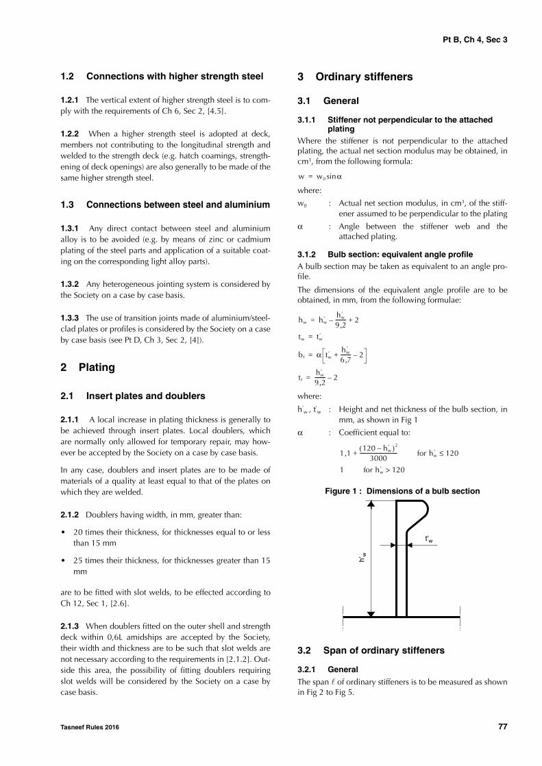
Pt B, Ch 4, Sec 3
Tasneef Rules 2016 77
1.2 Connections with higher strength steel
1.2.1 The vertical extent of higher strength steel is to com-ply with the requirements of Ch 6, Sec 2, [4.5].
1.2.2 When a higher strength steel is adopted at deck,members not contributing to the longitudinal strength andwelded to the strength deck (e.g. hatch coamings, strength-ening of deck openings) are also generally to be made of thesame higher strength steel.
1.3 Connections between steel and aluminium
1.3.1 Any direct contact between steel and aluminiumalloy is to be avoided (e.g. by means of zinc or cadmiumplating of the steel parts and application of a suitable coat-ing on the corresponding light alloy parts).
1.3.2 Any heterogeneous jointing system is considered bythe Society on a case by case basis.
1.3.3 The use of transition joints made of aluminium/steel-clad plates or profiles is considered by the Society on a caseby case basis (see Pt D, Ch 3, Sec 2, [4]).
2 Plating
2.1 Insert plates and doublers
2.1.1 A local increase in plating thickness is generally tobe achieved through insert plates. Local doublers, whichare normally only allowed for temporary repair, may how-ever be accepted by the Society on a case by case basis.
In any case, doublers and insert plates are to be made ofmaterials of a quality at least equal to that of the plates onwhich they are welded.
2.1.2 Doublers having width, in mm, greater than:
• 20 times their thickness, for thicknesses equal to or lessthan 15 mm
• 25 times their thickness, for thicknesses greater than 15mm
are to be fitted with slot welds, to be effected according toCh 12, Sec 1, [2.6].
2.1.3 When doublers fitted on the outer shell and strengthdeck within 0,6L amidships are accepted by the Society,their width and thickness are to be such that slot welds arenot necessary according to the requirements in [2.1.2]. Out-side this area, the possibility of fitting doublers requiringslot welds will be considered by the Society on a case bycase basis.
3 Ordinary stiffeners
3.1 General
3.1.1 Stiffener not perpendicular to the attached plating
Where the stiffener is not perpendicular to the attachedplating, the actual net section modulus may be obtained, incm3, from the following formula:
where:
w0 : Actual net section modulus, in cm3, of the stiff-ener assumed to be perpendicular to the plating
α : Angle between the stiffener web and theattached plating.
3.1.2 Bulb section: equivalent angle profileA bulb section may be taken as equivalent to an angle pro-file.
The dimensions of the equivalent angle profile are to beobtained, in mm, from the following formulae:
where:
h’w , t’w : Height and net thickness of the bulb section, in
mm, as shown in Fig 1
α : Coefficient equal to:
Figure 1 : Dimensions of a bulb section
3.2 Span of ordinary stiffeners
3.2.1 General
The span of ordinary stiffeners is to be measured as shownin Fig 2 to Fig 5.
w w0 αsin=
hw hw′ hw
′
9 2,-------- 2+–=
tw tw′=
bf α tw′ hw
′
6 7,-------- 2–+=
tfhw
′
9 2,-------- 2–=
1 1,120 hw
′–( )2
3000-----------------------------+ for hw
′ 120≤
1 for hw′ 120>
t'w
h'w
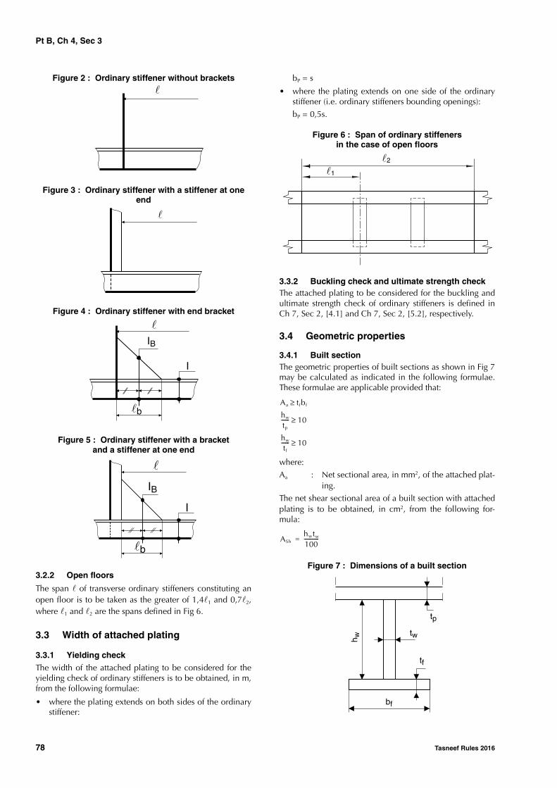
Pt B, Ch 4, Sec 3
78 Tasneef Rules 2016
Figure 2 : Ordinary stiffener without brackets
Figure 3 : Ordinary stiffener with a stiffener at one end
Figure 4 : Ordinary stiffener with end bracket
Figure 5 : Ordinary stiffener with a bracketand a stiffener at one end
3.2.2 Open floors
The span of transverse ordinary stiffeners constituting anopen floor is to be taken as the greater of 1,41 and 0,72,where 1 and 2 are the spans defined in Fig 6.
3.3 Width of attached plating
3.3.1 Yielding checkThe width of the attached plating to be considered for theyielding check of ordinary stiffeners is to be obtained, in m,from the following formulae:
• where the plating extends on both sides of the ordinarystiffener:
bP = s
• where the plating extends on one side of the ordinarystiffener (i.e. ordinary stiffeners bounding openings):
bP = 0,5s.
Figure 6 : Span of ordinary stiffenersin the case of open floors
3.3.2 Buckling check and ultimate strength checkThe attached plating to be considered for the buckling andultimate strength check of ordinary stiffeners is defined inCh 7, Sec 2, [4.1] and Ch 7, Sec 2, [5.2], respectively.
3.4 Geometric properties
3.4.1 Built sectionThe geometric properties of built sections as shown in Fig 7may be calculated as indicated in the following formulae.These formulae are applicable provided that:
where:
Aa : Net sectional area, in mm2, of the attached plat-ing.
The net shear sectional area of a built section with attachedplating is to be obtained, in cm2, from the following for-mula:
Figure 7 : Dimensions of a built section
�
�
�
�b
I
IB
�
�b
I
IB
�1
�2
Aa tfbf≥hw
tp
------ 10≥
hw
tf
------ 10≥
AShhwtw
100-----------=
tp
tf
tw
bf
h w

Pt B, Ch 4, Sec 3
Tasneef Rules 2016 79
The net section modulus of a built section with attachedplating is to be obtained, in cm3, from the following for-mula:
The distance from face plate to neutral axis is to beobtained, in cm, from the following formula:
The net moment of inertia of a built section with attachedplating is to be obtained, in cm4, from the following for-mula:
I = w v
3.4.2 Corrugations
Unless otherwise specified, the net section modulus of acorrugation is to be obtained, in cm3, from the followingformula:
where:
t : Net thickness of the plating of the corrugation,in mm
d, b, c : Dimensions of the corrugation, in mm, shownin Fig 8.
Figure 8 : Dimensions of a corrugation
At the corrugation ends, where the web continuity is notensured (e.g. where the corrugation webs are not supportedby local brackets) the net section modulus of the corruga-tion is to be obtained, in cm3, from the following formula:
A more precise calculation of the net section modulus maybe carried out taking into account the effectiveness of corru-gation webs. In general, the corrugation webs may be con-sidered 30% effective.
3.5 End connections
3.5.1 Where ordinary stiffeners are continuous throughprimary supporting members, they are to be connected tothe web plating so as to ensure proper transmission ofloads, e.g. by means of one of the connection details shownin Fig 9 to Fig 12.
Connection details other than those shown in Fig 9 toFig 12 may be considered by the Society on a case by casebasis. In some cases, the Society may require the details tobe supported by direct calculations submitted for review.
Figure 9 : End connection of ordinary stiffenerWithout collar plate
Figure 10 : End connection of ordinary stiffenerCollar plate
Figure 11 : End connection of ordinary stiffenerOne large collar plate
Figure 12 : End connection of ordinary stiffenerTwo large collar plates
3.5.2 Where ordinary stiffeners are cut at primary support-ing members, brackets are to be fitted to ensure the struc-tural continuity. Their net section modulus and their netsectional area are to be not less than those of the ordinarystiffeners.
The net thickness of brackets is to be not less than that ofordinary stiffeners. Brackets with net thickness, in mm, lessthan 15Lb, where Lb is the length, in m, of the free edge ofthe end bracket, are to be flanged or stiffened by a weldedface plate. The net sectional area, in cm2, of the flangededge or face plate is to be at least equal to 10Lb .
3.5.3 Where necessary, the Society may require backingbrackets to be fitted, as shown in Fig 13, in order to improvethe fatigue strength of the connection (see also [4.7.4]).
whwtfbf
1000--------------
tWhW2
6000------------- 1
Aa tfbf–
AatWhW
2------------+
-------------------------+
+=
vhW Aa 0 5tWhW,+( )
10 Aa tfbf tWhW+ +( )---------------------------------------------------=
w td6----- 3b c+( )10 3–=
w 0 5 btd10 3–,=

Pt B, Ch 4, Sec 3
80 Tasneef Rules 2016
Figure 13 : End connection of ordinary stiffenerBacking bracket
4 Primary supporting members
4.1 Span of primary supporting members
4.1.1 The span of primary supporting members is to bedetermined in accordance with [3.2].
4.2 Width of attached plating
4.2.1 GeneralThe width of the attached plating to be considered for theyielding check of primary supporting members analysedthrough beam structural models is to be obtained, in m,from the following formulae:
• where the plating extends on both sides of the primarysupporting member:
bP = min (s; 0,2)
• where the plating extends on one side of the primarysupporting member (i.e. primary supporting membersbounding openings):
bP = 0,5 min (s; 0,2)
4.2.2 Corrugated bulkheadsThe width of attached plating of corrugated bulkhead pri-mary supporting members is to be determined as follows:
• when primary supporting members are parallel to thecorrugations and are welded to the corrugation flanges,the width of the attached plating is to be calculated inaccordance with [4.2.1] and is to be taken not greaterthan the corrugation flange width
• when primary supporting members are perpendicular tothe corrugations, the width of the attached plating is tobe taken equal to the width of the primary supportingmember face plate.
4.3 Geometric properties
4.3.1 Standard roll sectionsThe geometric properties of primary supporting membersmade of standard roll sections may be determined inaccordance with [3.4.1].
4.3.2 Built sectionsThe geometric properties of primary supporting membersmade of built sections (including primary supporting mem-bers of double skin structures, such as double bottom floors
and girders) are generally determined in accordance with[3.4.1].
Additional requirements relevant to the net shear sectionalarea are provided in [4.3.3].
4.3.3 Net shear sectional area in the case of web large openings
Where large openings are fitted in the web of primary sup-porting members (e.g. where a pipe tunnel is fitted in thedouble bottom, see Fig 14), their influence is to be takeninto account by assigning an equivalent net shear sectionalarea to the primary supporting member.
This equivalent net shear sectional area is to be obtained, incm2, from the following formula:
where (see Fig 14):
I1, I2 : Net moments of inertia, in cm4, of deep webs(1) and (2), respectively, with attached platingaround their neutral axes parallel to the plating
ASh1, ASh2 : Net shear sectional areas, in cm2, of deep webs(1) and (2), respectively, to be calculatedaccording to [4.3.2]
: Span, in cm, of deep webs (1) and (2).
Figure 14 : Large openings in the web ofprimary supporting members
4.4 Bracketed end connections
4.4.1 Arm lengths of end brackets are to be equal, as far aspracticable.
With the exception of primary supporting members of trans-versely framed single sides (see Sec 5, [3.2]), the height ofend brackets is to be not less than that of the primary sup-porting member.
4.4.2 The net thickness of the end bracket web is generallyto be not less than that of the primary supporting memberweb.
4.4.3 The net scantlings of end brackets are generally to besuch that the net section modulus of the primary supportingmember with end brackets is not less than that of the pri-mary supporting member at mid-span.
AShASh1
10 00322, ASh1
I1
----------------------------------+
--------------------------------------------ASh2
10 00322, ASh2
I2
----------------------------------+
--------------------------------------------+=

Pt B, Ch 4, Sec 3
Tasneef Rules 2016 81
4.4.4 The width, in mm, of the face plate of end brackets isto be not less than 50(Lb+1), where Lb is the length, in m, ofthe free edge of the end bracket.Moreover, the net thickness of the face plate is to be not lessthan that of the bracket web.
4.4.5 Stiffening of end brackets is to be designed such thatit provides adequate buckling web stability.As guidance, the following prescriptions may be applied:• where the length Lb is greater than 1,5 m, the web of the
bracket is to be stiffened
• the net sectional area, in cm2, of web stiffeners is to benot less than 16,5, where is the span, in m, of thestiffener
• tripping flat bars are to be fitted to prevent lateral buck-ling of web stiffeners. Where the width of the symmetri-cal face plate is greater than 400 mm, additionalbacking brackets are to be fitted.
4.4.6 In addition to the above requirements, the net scant-lings of end brackets are to comply with the applicablerequirements given in Sec 4 to Sec 7.
4.5 Bracketless end connections
4.5.1 In the case of bracketless crossing between primarysupporting members (see Fig 15), the net thickness of thecommon part of the web is to be not less than the valueobtained, in mm, from the following formula:
where: w : the lesser of w1 and w2,MAX
w1 : gross section modulus, in cm3, of member 1w2,MAX : the greater value, in cm3, of the gross section
moduli of members 2 and 3Ω : Area, in cm2, of the common part of members
1, 2 and 3.In the absence of one of members 2 and 3 shown in Fig 15,the value of the relevant gross section modulus is to betaken equal to zero.
4.5.2 In no case may the net thickness calculated accord-ing to [4.5.1] be less than the smallest web net thickness ofthe members forming the crossing.
4.5.3 In general, the continuity of the face plates is to beensured.
4.6 Cut-outs and holes
4.6.1 Cut-outs for the passage of ordinary stiffeners are tobe as small as possible and well rounded with smoothedges.In general, the depth of cut-outs is to be not greater than50% of the depth of the primary supporting member.
4.6.2 Where openings such as lightening holes are cut inprimary supporting members, they are to be equidistantfrom the face plate and corners of cut-outs and, in general,their height is to be not greater than 20% of the web height.
4.6.3 Openings may not be fitted in way of toes of endbrackets.
Figure 15 : Bracketless end connections ofprimary supporting members
Figure 16 : Large openings in primary supporting members - Secondary stresses
4.6.4 Over half of the span of primary supporting mem-bers, the length of openings is to be not greater than the dis-tance between adjacent openings.
At the ends of the span, the length of openings is to be notgreater than 25% of the distance between adjacent open-ings.
4.6.5 In the case of large openings as shown in Fig 16, thesecondary stresses in primary supporting members are to beconsidered for the reinforcement of the openings.
The secondary stresses may be calculated in accordancewith the following procedure.
Members (1) and (2) are subjected to the following forces,moments and stresses:
t 15 75wΩ----,=
Ω
Member 3
Member 1
Member 2

Pt B, Ch 4, Sec 3
82 Tasneef Rules 2016
where:MA, MB : Bending moments, in kN.m, in sections A and B
of the primary supporting memberm1, m2 : Bending moments, in kN.m, in (1) and (2)d : Distance, in m, between the neutral axes of (1)
and (2)σF1, σF2 : Axial stresses, in N/mm2, in (1) and (2)σm1, σm2 : Bending stresses, in N/mm2, in (1) and (2)QT : Shear force, in kN, equal to QA or QB, which-
ever is greaterτ1, τ2 : Shear stresses, in N/mm2, in (1) and (2)w1, w2 : Net section moduli, in cm3, of (1) and (2)S1, S2 : Net sectional areas, in cm2, of (1) and (2)Sw1, Sw2 : Net sectional areas, in cm2, of webs in (1) and
(2)I1, I2 : Net moments of inertia, in cm4, of (1) and (2)
with attached plating
The combined stress σC calculated at the ends of members(1) and (2) is to be obtained from the following formula:
The combined stress σC is to comply with the checking cri-teria in Ch 7, Sec 3, [3.6] or Ch 7, Sec 3, [4.3], as applica-ble. Where these checking criteria are not complied with,the cut-out is to be reinforced according to one of the solu-tions shown in Fig 17 to Fig 19:• continuous face plate (solution 1): see Fig 17• straight face plate (solution 2): see Fig 18• compensation of the opening (solution 3): see Fig 19• combination of the above solutions.
Other arrangements may be accepted provided they aresupported by direct calculations submitted to the Society forreview.
Figure 17 : Stiffening of large openings in primary supporting members - Solution 1
Figure 18 : Stiffening of large openings in primary supporting members - Solution 2
Figure 19 : Stiffening of large openings in primary supporting members - Solution 3
Inserted plate
4.7 Stiffening arrangement
4.7.1 Webs of primary supporting members are generallyto be stiffened where the height, in mm, is greater than100t, where t is the web net thickness, in mm, of the pri-mary supporting member.In general, the web stiffeners of primary supporting mem-bers are to be spaced not more than 110t.
4.7.2 Where primary supporting member web stiffenersare welded to ordinary stiffener face plates, their net sec-tional area at the web stiffener mid-height is to be not lessthan the value obtained, in cm2, from the following formula:
where:k1 : Coefficient depending on the web connection
with the ordinary stiffener, to be taken as:• k1 = 0,3 for connections without collar plate
(see Fig 9)• k1 = 0,225 for connections with a collar
plate (see Fig 10)• k1 = 0,2 for connections with one or two
large collar plates (see Fig 11 and Fig 12)
FMA MB+
2d----------------------=
m1MA MB–
2--------------------- K1=
m2MA MB–
2--------------------- K2=
σF1 10 FS1
-----=
σF2 10 FS2
-----=
σm1m1
w1
-------103=
σm2m2
w2
-------103=
τ1 10K1QT
Sw1
-------------=
τ2 10K2QT
Sw2
-------------=
K1I1
I1 I2+--------------=
K2I2
I1 I2+--------------=
σc σF σm+( )2 3τ2+=
t t
A 0 1k, 1 γS2pS γW2pW+( )s=
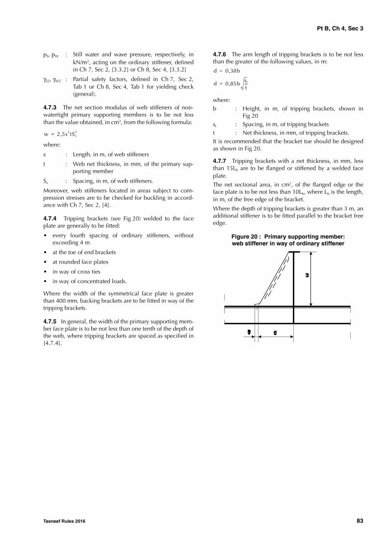
Pt B, Ch 4, Sec 3
Tasneef Rules 2016 83
pS, pW : Still water and wave pressure, respectively, inkN/m2, acting on the ordinary stiffener, definedin Ch 7, Sec 2, [3.3.2] or Ch 8, Sec 4, [3.3.2]
γS2, γW2 : Partial safety factors, defined in Ch 7, Sec 2,Tab 1 or Ch 8, Sec 4, Tab 1 for yielding check(general).
4.7.3 The net section modulus of web stiffeners of non-watertight primary supporting members is to be not lessthan the value obtained, in cm3, from the following formula:
where:
s : Length, in m, of web stiffeners
t : Web net thickness, in mm, of the primary sup-porting member
Ss : Spacing, in m, of web stiffeners.
Moreover, web stiffeners located in areas subject to com-pression stresses are to be checked for buckling in accord-ance with Ch 7, Sec 2, [4].
4.7.4 Tripping brackets (see Fig 20) welded to the faceplate are generally to be fitted:
• every fourth spacing of ordinary stiffeners, withoutexceeding 4 m
• at the toe of end brackets
• at rounded face plates
• in way of cross ties
• in way of concentrated loads.
Where the width of the symmetrical face plate is greaterthan 400 mm, backing brackets are to be fitted in way of thetripping brackets.
4.7.5 In general, the width of the primary supporting mem-ber face plate is to be not less than one tenth of the depth ofthe web, where tripping brackets are spaced as specified in[4.7.4].
4.7.6 The arm length of tripping brackets is to be not lessthan the greater of the following values, in m:
where:b : Height, in m, of tripping brackets, shown in
Fig 20 st : Spacing, in m, of tripping bracketst : Net thickness, in mm, of tripping brackets.It is recommended that the bracket toe should be designedas shown in Fig 20.
4.7.7 Tripping brackets with a net thickness, in mm, lessthan 15Lb are to be flanged or stiffened by a welded faceplate.
The net sectional area, in cm2, of the flanged edge or theface plate is to be not less than 10Lb, where Lb is the length,in m, of the free edge of the bracket.
Where the depth of tripping brackets is greater than 3 m, anadditional stiffener is to be fitted parallel to the bracket freeedge.
Figure 20 : Primary supporting member:web stiffener in way of ordinary stiffener
w 2 5s2tSs2,=
d 0 38b,=
d 0 85b st
t---,=
Pt B, Ch 4, Sec 4
84 Tasneef Rules 2016
SECTION 4 BOTTOM STRUCTURE
1 General
1.1 Application
1.1.1 The requirements of this Section apply to longitudi-nally or transversely framed single and double bottom struc-tures.
1.2 General arrangement
1.2.1 In ships greater than 120 m in length, the bottom is,in general, to be longitudinally framed.
1.2.2 The bottom is to be checked by the Designer toascertain that it withstands the loads resulting from the dry-docking of the ship.
1.2.3 The bottom is to be locally stiffened where concen-trated loads are envisaged.
1.2.4 Girders or floors are to be fitted under each line ofpillars, when deemed necessary by the Society on the basisof the loads carried by the pillars.
1.2.5 Adequate tapering is to be provided between doublebottom and adjacent single bottom structures. Similarly,adequate continuity is to be provided in the case of heightvariation in the double bottom. Where such a height varia-tion occurs within 0,6 L amidships, the inner bottom is gen-erally to be maintained continuous by means of inclinedplating.
1.2.6 Provision is to be made for the free passage of waterfrom all parts of the bottom to the suctions, taking intoaccount the pumping rate required.
1.2.7 When solid ballast is fitted, it is to be securely posi-tioned. If necessary, intermediate floors may be required forthis purpose.
1.3 Keel
1.3.1 The width of the keel is to be not less than the valueobtained, in m, from the following formula:
1.4 Drainage and openings for air passage
1.4.1 Holes are to be cut into floors and girders to ensurethe free passage of air and liquids from all parts of the dou-ble bottom.
1.4.2 Air holes are to be cut as near to the inner bottomand draining holes as near to the bottom shell as practica-ble.
2 Longitudinally framed single bottom
2.1 General
2.1.1 Single bottom ships are to be fitted with a centregirder formed by a vertical continuous or intercostal webplate and a horizontal face plate continuous over the floors.
Intercostal web plates are to be aligned and welded tofloors.
2.1.2 In general, girders are to be fitted spaced not morethan 2,5 m apart and formed by a vertical intercostal webplate and a horizontal face plate continuous over the floors.
Intercostal web plates are to be aligned and welded tofloors.
2.1.3 Centre and side girders are to be extended as far aftand forward as practicable.
2.1.4 Where side girders are fitted in lieu of the centregirder, the scarfing is to be adequately extended and addi-tional stiffening of the centre bottom may be required.
2.1.5 Longitudinal girders are to be fitted in way of eachline of pillars.
2.1.6 Floors are to be made with a welded face platebetween the collision bulkhead and 0,25L from the foreend.
2.2 Floors
2.2.1 In general, the floor spacing is to be not greater than5 frame spacings.
2.3 Longitudinal ordinary stiffeners
2.3.1 Longitudinal ordinary stiffeners are generally to becontinuous when crossing primary members.
3 Transversely framed single bottom
3.1 General
3.1.1 The requirements in [2.1] apply also to transverselyframed single bottoms.
3.2 Floors
3.2.1 Floors are to be fitted at every frame.
3.2.2 The height, in m, of floors at the centreline is to benot less than B/16. In the case of ships with considerablerise of floor, this height may be required to be increased soas to assure a satisfactory connection to the frames.
b 0 8 0 5 L100----------,+,=

Pt B, Ch 4, Sec 4
Tasneef Rules 2016 85
4 Longitudinally framed double bot-tom
4.1 General
4.1.1 The centre girder is to be continuous and extendedover the full length of ship and the spacing of adjacent lon-gitudinal girders is generally to be not greater than 6,5 m.
4.2 Double bottom height
4.2.1 The double bottom height is to be sufficient toensure access to all parts and, in way of the centre girder, isto be not less than the greater value obtained, in m, fromthe following formulae:
4.2.2 Where the height of the double bottom varies, thevariation is generally to be made gradually and over an ade-quate length; the knuckles of inner bottom plating are to belocated in way of plate floors.
Where this is impossible, suitable longitudinal structuressuch as partial girders, longitudinal brackets etc., fittedacross the knuckle are to be arranged.
4.2.3 In ships without a flat bottom, the height of doublebottom specified in [4.2.1] may be required to be ade-quately increased such as to ensure sufficient access to theareas towards the sides.
4.3 Floors
4.3.1 The spacing of plate floors, in m, is generally to benot greater than 0,05L or 3,8 m, whichever is the lesser.
Additional plate floors are to be fitted in way of transversewatertight bulkheads.
4.3.2 Plate floors are generally to be provided with stiffen-ers in way of longitudinal ordinary stiffeners.
4.3.3 Where the double bottom height exceeds 0,9 m,watertight floors are to be fitted with stiffeners having a netsection modulus not less than that required for tank bulk-head vertical stiffeners.
4.4 Bottom and inner bottom longitudinal ordinary stiffeners
4.4.1 Bottom and inner bottom longitudinal ordinary stiff-eners are generally to be continuous through the floors.
4.5 Brackets to centreline girder and margin plate
4.5.1 In general, intermediate brackets are to be fitted con-necting either the margin plate or the centre girder to thenearest bottom and inner bottom ordinary stiffeners.
4.5.2 Such brackets are to be stiffened at the edge with aflange having a width not less than 1/10 of the local doublebottom height.
If necessary, the Society may require a welded flat bar to bearranged in lieu of the flange.
4.5.3 Where the side shell is transversely stiffened, marginplate brackets are to be fitted at every frame.
4.6 Duct keel
4.6.1 Where a duct keel is arranged, the centre girder maybe replaced by two girders conveniently spaced, generallyno more than 2 m apart.
4.6.2 The structures in way of the floors are to ensure suffi-cient continuity of the latter.
4.7 Bilge wells
4.7.1 Bilge wells arranged in the double bottom are to belimited in depth and formed by steel plates having a netthickness not less than the greater of that required for water-tight floors and that required for the inner bottom.
4.7.2 In ships subject to subdivision requirements, suchbilge wells are to be fitted so that the distance of their bot-tom from the shell plating is not less than 460 mm.
4.7.3 Where there is no margin plate, well arrangement isconsidered by the Society on a case by case basis.
5 Transversely framed double bottom
5.1 General
5.1.1 The requirements in [4.1], [4.2], [4.5], [4.6] and[4.7] apply also to transversely framed double bottoms.
5.2 Floors
5.2.1 Plate floors are to be fitted at every frame forward of0,75L from the aft end.
Plate floors are also to be fitted:
• in way of transverse watertight bulkheads
• in way of double bottom steps.
Elsewhere, plate floors may be arranged at a distance notexceeding 3 m.
5.2.2 In general, plate floors are to be continuous betweenthe centre girder and the margin plate.
5.2.3 Open floors are to be fitted in way of intermediateframes.
5.2.4 Where the double bottom height exceeds 0,9 m,plate floors are to be fitted with vertical stiffeners spaced notmore than 1,5 m apart.
These stiffeners may consist of flat bars with a width equalto one tenth of the floor depth and a net thickness, in mm,not less than 0,8L0,5.
hDB 3B T 10+ +100
--------------------------=
hDB 0 7,=

Pt B, Ch 4, Sec 4
86 Tasneef Rules 2016
5.3 Girders
5.3.1 Side girders are to be arranged in such a way thattheir distance to adjacent girders or margin plate does notgenerally exceed 4,5 m.
5.3.2 Where the double bottom height exceeds 0,9 m, lon-gitudinal girders are to be fitted with vertical stiffenersspaced not more than 1,5 m apart. These stiffeners may consist of flat bars with a width equalto one tenth of the girder height and a net thickness, in mm,not less than 0,8L0,5.
5.3.3 In way of open floors, side girders are to be providedwith stiffeners having a web height which is generally to benot less than 150 mm.
5.4 Open floors
5.4.1 At each frame between plate floors, open floors areto be arranged consisting of a frame connected to the bot-tom plating and a reverse frame connected to the inner bot-tom plating (See Fig 1).
5.4.2 Open floors are to be attached to the centrelinegirder and to the margin plate by means of flanged bracketshaving a width of flange not less than 1/10 of the local dou-ble bottom height.
5.4.3 Where frames and reverse frames are interrupted inway of girders, double brackets are to be fitted.
Figure 1 : Open floor
6 Bilge keel
6.1 Arrangement, scantlings and connec-tions
6.1.1 ArrangementBilge keels may not be welded directly on the shell plating.An intermediate flat, or doubler, is required on the shellplating.
The ends of the bilge keel are to be sniped at an angle of15° or rounded with large radius. They are to be located inway of a transverse bilge stiffener. The ends of the interme-diate flat are to be sniped at an angle of 15°.
The arrangement shown in Fig 2 is recommended.
Figure 2 : Bilge keel arrangement
The arrangement shown in Fig 3 may also be accepted.
Figure 3 : Bilge keel arrangement
6.1.2 MaterialsThe bilge keel and the intermediate flat are to be made ofsteel with the same yield stress and grade as that of the bilgestrake.
6.1.3 ScantlingsThe net thickness of the intermediate flat is to be equal tothat of the bilge strake. However, this thickness may gener-ally not be greater than 15 mm.
6.1.4 WeldingWelding of bilge keel and intermediate plate connections isto be in accordance with Ch 12, Sec 1, [3.2].

Pt B, Ch 4, Sec 5
Tasneef Rules 2016 87
SECTION 5 SIDE STRUCTURE
1 General
1.1 Application
1.1.1 The requirements of this Section apply to longitudi-nally or transversely framed single and double side struc-tures.
1.1.2 The transversely framed side structures are built withtransverse frames possibly supported by side girders (see[5.3.1]).
1.1.3 The longitudinally framed side structures are builtwith longitudinal ordinary stiffeners supported by side verti-cal primary supporting members.
1.2 General arrangement
1.2.1 Unless otherwise specified, side girders are to be fit-ted aft of the collision bulkhead up to 0,2L aft of the foreend, in line with fore peak girders.
1.2.2 Side vertical primary supporting members are to befitted in way of hatch end beams.
1.3 Sheerstrake
1.3.1 The width of the sheerstrake is to be not less than thevalue obtained, in m, from the following formula:
However, the sheerstrake is also to comply with the require-ments in Sec 1, [2.5.5].
1.3.2 The sheerstrake may be either welded to the stringerplate or rounded. If it is rounded, the radius, in mm, is to benot less than 17tS , where tS is the net thickness, in mm, ofthe sheerstrake.
1.3.3 The upper edge of the welded sheerstrake is to berounded and free of notches.
1.3.4 The transition from a rounded sheerstrake to anangled sheerstrake associated with the arrangement ofsuperstructures at the ends of the ship is to be carefullydesigned so as to avoid any discontinuities.Plans showing details of this transition are to be submittedfor approval to the Society.
2 Longitudinally framed single side
2.1 Longitudinal ordinary stiffeners
2.1.1 Longitudinal ordinary stiffeners are generally to becontinuous when crossing primary members.
2.2 Primary supporting members
2.2.1 In general, the side vertical primary supporting mem-ber spacing may not exceed 5 frame spacings.
2.2.2 In general, the side vertical primary supporting mem-bers are to be bracketed to the double bottom transversefloors.
3 Transversely framed single side
3.1 Frames
3.1.1 Transverse frames are to be fitted at every frame.
3.1.2 Frames are generally to be continuous when crossingprimary members.
Otherwise, the detail of the connection is to be examinedby the Society on a case by case basis.
3.1.3 In general, the net section modulus of ‘tween deckframes is to be not less than that required for frames locatedimmediately above.
3.2 Primary supporting members
3.2.1 In 'tweendecks of more than 4 m in height, side gird-ers or side vertical primary supporting members or bothmay be required by the Society.
3.2.2 Side girders are to be flanged or stiffened by awelded face plate.
The width of the flanged edge or face plate is to be not lessthan 22t, where t is the web net thickness, in mm, of thegirder.
3.2.3 The height of end brackets is to be not less than halfthe height of the primary supporting member.
4 Longitudinally framed double side
4.1 General
4.1.1 Adequate continuity of strength is to be ensured inway of breaks or changes in width of the double side.
In particular, scarfing of the inner side is to be ensuredbeyond the cargo hold region.
4.1.2 Knuckles of the inner side are to be adequately stiff-ened by longitudinal stiffeners. Equivalent arrangement maybe considered by the Society on a case by case basis.
b 0 715, 0 425 L100----------,+=

Pt B, Ch 4, Sec 5
88 Tasneef Rules 2016
4.2 Primary supporting members
4.2.1 The height of side vertical primary supporting mem-bers may be gradually tapered from bottom to deck. Themaximum acceptable taper, however, is 8 cm per metre.
4.2.2 Side vertical primary supporting members supportedby a strut and two diagonals converging on the former areto be considered by the Society on a case by case basis.
5 Transversely framed double side
5.1 General
5.1.1 The requirements in [4.1] also apply to transverselyframed double side.
5.1.2 Transverse frames may be connected to the verticalordinary stiffeners of the inner side by means of struts.
Struts are generally to be connected to transverse framesand vertical ordinary stiffeners of the inner side by means ofvertical brackets.
5.2 Frames
5.2.1 Transverse frames are to be fitted at every frame.
5.3 Primary supporting members
5.3.1 Unless otherwise specified, transverse frames are tobe supported by side girders if D ≥ 6 m.
These girders are to be supported by side vertical primarysupporting members spaced no more than 3,8 m apart.
5.3.2 In the case of ships having 4,5 < D < 6 m, side verti-cal primary supporting members are to be fitted, in generalnot more than 5 frame spacings apart.
6 Frame connections
6.1 General
6.1.1 End connections of frames are to be bracketed.
6.1.2 'Tweendeck frames are to be bracketed at the topand welded or bracketed at the bottom to the deck.
In the case of bulb profiles, a bracket may be required to befitted at bottom.
6.1.3 Brackets are normally connected to frames by lapwelds. The length of overlap is to be not less than the depthof frames.
6.2 Upper brackets of frames
6.2.1 The arm length of upper brackets connecting framesto deck beams is to be not less than the value obtained, inmm, from the following formula:
where:
ϕ : coefficient equal to:
• for unflanged brackets:
ϕ = 48
• for flanged brackets:
ϕ = 43,5
w : required net section modulus of the stiffener, incm3, given in [6.2.2] and [6.2.3] and dependingon the type of connection,
t : bracket net thickness, in mm.
6.2.2 For connections of perpendicular stiffeners locatedin the same plane (see Fig 1) or connections of stiffenerslocated in perpendicular planes (see Fig 2), the required netsection modulus is to be taken equal to:
where w1 and w2 are the required net section moduli ofstiffeners, as shown in Fig 1 and Fig 2.
Figure 1 : Connections of perpendicular stiffenersin the same plane
Figure 2 : Connections of stiffeners locatedin perpendicular planes
d ϕ w 30+t
-----------------=
w w2 if w2 w1≤=
w w1 if w2 w1>=
w2
w1
d
d
w2
w1
d
d
theoriticalbracket
actualbracket

Pt B, Ch 4, Sec 5
Tasneef Rules 2016 89
6.2.3 For connections of frames to deck beams (see Fig 3),the required net section modulus is to be taken equal to:
• for bracket “A”:
• for bracket “B”:
wB = w’1 need not be greater than w1
where w1 , w’1 and w2 are the required net section moduliof stiffeners, as shown in Fig 3.
Figure 3 : Connections of frames to deck beams
6.3 Lower brackets of frames
6.3.1 In general, frames are to be bracketed to the innerbottom or to the face plate of floors as shown in Fig 4.
6.3.2 The arm lengths d1 and d2 of lower brackets offrames are to be not less than the value obtained, in mm,from the following formula:
where:
ϕ : coefficient equal to:
• for unflanged brackets:
ϕ = 50
• for flanged brackets:
ϕ = 45
w : required net section modulus of the frame, incm3,
t : Bracket net thickness, in mm.
6.3.3 Where the bracket net thickness, in mm, is less than15Lb , where Lb is the length, in m, of the bracket free edge,the free edge of the bracket is to be flanged or stiffened by awelded face plate.
The net sectional area, in cm2, of the flange or the face plateis to be not less than 10Lb.
7 Openings in the shell plating
7.1 Position of openings
7.1.1 Openings in the shell plating are to be located at avertical distance from the decks at side not less than:
• two times the opening diameter, in case of circularopening
• the opening minor axis, in case of elliptical openings.
See also Sec 6, Fig 1.
7.2 Local strengthening
7.2.1 Openings in the ship sides, e.g. for cargo ports, areto be well rounded at the corners and located well clear ofsuperstructure ends or any openings in the deck areas atsides of hatchways.
7.2.2 Openings for sea intakes are to be well rounded atthe corners and, within 0,6 L amidships, located outside thebilge strakes. Where arrangements are such that sea intakesare unavoidably located in the curved zone of the bilgestrakes, such openings are to be elliptical with the majoraxis in the longitudinal direction. Openings for stabiliserfins are considered by the Society on a case by case basis.The thickness of sea chests is generally to be that of thelocal shell plating, but in no case less than 12 mm.
Figure 4 : Lower brackets of main frames
wA w1 if w2 w1≤=
wA w2 if w2 w1>=
w2
w1
dA
w'1
dA
dB
d B
h'1
h'1
A
B
d ϕ w 30+t
-----------------=
d1
d2
h
2 h
1,5
h
75
75

Pt B, Ch 4, Sec 5
90 Tasneef Rules 2016
7.2.3 Openings in [7.2.1] and [7.2.2] and, when deemednecessary by the Society, other openings of considerablesize are to be adequately compensated by means of insertplates of increased thickness or doublers sufficientlyextended in length. Such compensation is to be partial ortotal depending on the stresses occurring in the area of theopenings.
Circular openings on the sheerstrake need not be compen-sated where their diameter does not exceed 20% of thesheerstrake minimum width, defined in [1.3], or 380 mm,whichever is the lesser, and where they are located awayfrom openings on deck at the side of hatchways or super-
structure ends.

Pt B, Ch 4, Sec 6
Tasneef Rules 2016 91
SECTION 6 DECK STRUCTURE
1 General
1.1 Application
1.1.1 The requirements of this Section apply to longitudi-nally or transversely framed deck structures.
1.2 General arrangement
1.2.1 The deck supporting structure consists of ordinarystiffeners (beams or longitudinals), longitudinally or trans-versely arranged, supported by primary supporting mem-bers which may be sustained by pillars.
1.2.2 Where beams are fitted in a hatched deck, these areto be effectively supported by at least two longitudinal gird-ers located in way of hatch side girders to which they are tobe connected by brackets and/or clips.
1.2.3 In ships greater than 120 m in length, the zones out-side the line of openings of the strength deck and otherdecks contributing to longitudinal strength are, in general,to be longitudinally framed.Where a transverse framing type is adopted for such ships, itis considered by the Society on a case by case basis.
1.2.4 Adequate continuity of strength is to be ensured inway of:• stepped strength decks• changes in the framing system.
Details of structural arrangements are to be submitted forreview to the Society.
1.2.5 Where applicable, deck transverses of reinforcedscantlings are to be aligned with floors.
1.2.6 Inside the line of openings, a transverse structure isgenerally to be adopted for cross-deck structures, beams areto be adequately supported by girders and, in ships greaterthan 120 m in length, extend up to the second longitudinalfrom the hatch side girders toward the bulwark.Where this is impracticable, intercostal stiffeners are to befitted between the hatch side girder and the second longitu-dinal.
Other structural arrangements may be accepted, subject totheir strength verification. In particular, their bucklingstrength against the transverse compression loads is to bechecked. Where needed, deck transverses may be requiredto be fitted.
1.2.7 Deck supporting structures under deck machinery,cranes and king posts are to be adequately stiffened.
1.2.8 Pillars or other supporting structures are generally tobe fitted under heavy concentrated cargoes.
1.2.9 Special arrangements, such as girders supported bycantilevers, are considered by the Society on a case by casebasis.
1.2.10 Where devices for vehicle lashing arrangementsand/or corner fittings for containers are directly attached todeck plating, provision is to be made for the fitting of suita-ble additional reinforcements of the sizes required by theload carried.
1.2.11 Stiffeners are also to be fitted in way of the ends andcorners of deck houses and partial superstructures.
1.3 Construction of watertight decks
1.3.1 Watertight decks are to be of the same strength aswatertight bulkheads at corresponding levels. The meansused for making them watertight, and the arrangementsadopted for closing openings in them, are to be to the satis-faction of the Society.
1.4 Stringer plate
1.4.1 The width of the stringer plate is to be not less thanthe value obtained, in m, from the following formula:
However, the stringer plate is also to comply with therequirements in Sec 1, [2.5.5].
1.4.2 Stringer plates of lower decks not extending over thefull ship's length are to be gradually tapered or overlappedby adequately sized brackets.
2 Longitudinally framed deck
2.1 General
2.1.1 Deck longitudinals are to be continuous, as far aspracticable, in way of deck transverses and transverse bulk-heads.
Other arrangements may be considered, provided adequatecontinuity of longitudinal strength is ensured.
2.1.2 In general, the spacing of deck transverses is not toexceed 5 frame spacings.
2.2 Longitudinal ordinary stiffeners
2.2.1 In ships equal to or greater than 120 m in length,strength deck longitudinal ordinary stiffeners are to be con-tinuous through the watertight bulkheads and/or deck trans-verses.
b 0 35, 0 5 L100----------,+=

Pt B, Ch 4, Sec 6
92 Tasneef Rules 2016
2.2.2 Frame brackets, in ships with transversely framedsides, are generally to have their horizontal arm extended tothe adjacent longitudinal ordinary stiffener.
3 Transversely framed deck
3.1 General
3.1.1 In general, deck beams are to be fitted at each frame.
4 Pillars
4.1 General
4.1.1 Pillars are to be fitted, as far as practicable, in thesame vertical line.
4.1.2 In general, pillars are to be fitted below winches,cranes, windlasses and steering gear, in the engine roomand at the corners of deckhouses.
4.1.3 In tanks, solid or open section pillars are generally tobe fitted. Pillars located in spaces intended for productswhich may produce explosive gases are to be of open sec-tion type.
4.1.4 Tight or non-tight bulkheads may be considered aspillars, provided that their arrangement complies withSec 7, [4].
4.2 Connections
4.2.1 Heads and heels of pillars are to be attached to thesurrounding structure by means of brackets, insert plates sothat the loads are well distributed.
Insert plates may be replaced by doubling plates, except inthe case of pillars which may also work under tension suchas those in tanks.
In general, the net thickness of doubling plates is to be notless than 1,5 times the net thickness of the pillar.
4.2.2 Pillars are to be attached at their heads and heels bycontinuous welding.
4.2.3 Pillars are to be connected to the inner bottom at theintersection of girders and floors.
4.2.4 Where pillars connected to the inner bottom are notlocated in way of intersections of floors and girders, partialfloors or girders or equivalent structures suitable to supportthe pillars are to be arranged.
4.2.5 Manholes may not be cut in the girders and floorsbelow the heels of pillars.
4.2.6 Where pillars are fitted in tanks, head and heelbrackets may be required if tensile stresses are expected.
4.2.7 Where side pillars are not fitted in way of hatchends, vertical stiffeners of bulkheads supporting hatch sidegirders or hatch end beams are to be bracketed at theirends.
5 Hatch supporting structures
5.1 General
5.1.1 Hatch side girders and hatch end beams of rein-forced scantlings are to be fitted in way of cargo hold open-ings.
In general, hatched end beams and deck transverses are tobe in line with bottom and side transverse structures, so asto form a reinforced ring.
5.1.2 Clear of openings, adequate continuity of strength oflongitudinal hatch coamings is to be ensured by underdeckgirders.
5.1.3 The details of connection of deck transverses to lon-gitudinal girders and web frames are to be submitted to theSociety for approval.
6 Openings in the strength deck
6.1 Position of openings and local strength-ening
6.1.1 Openings in the strength deck are to be kept to aminimum and spaced as far apart from one another andfrom breaks of effective superstructures as practicable.Openings are generally to be cut outside the hatched areas;in particular, they are to be cut as far as practicable fromhatchway corners.
The dashed areas in Fig 1 are those where openings aregenerally to be avoided. The meaning of the symbols inFig 1 is as follows:
c, e : Longitudinal and transverse dimensions ofhatched area:
c = 0,07 + 0,10 b without being less than0,25 b,
e = 0,25 (B - b)
a : Transverse dimension of openings
g : Transverse dimension of the area where open-ings are generally to be avoided in way of theconnection between deck and side (as shown inFig 1), deck and longitudinal bulkheads, deckand large deck girders:
• in the case of circular openings:
g = 2 a
• in the case of elliptical openings:
g = a
6.1.2 No compensation is required where the openingsare:
• circular of less than 350 mm in diameter and at a dis-tance from any other opening in compliance with Fig 2
• elliptical with the major axis in the longitudinal direc-tion and the ratio of the major to minor axis not lessthan 2.

Pt B, Ch 4, Sec 6
Tasneef Rules 2016 93
Figure 1 : Position of openings in the strength deck
Figure 2 : Circular openings in the strength deck
6.2 Corners of hatchways
6.2.1 For hatchways located within the cargo area, insertplates, whose thickness is to be determined according to[6.2.3], are generally to be fitted in way of corners wherethe plating cut-out has a circular profile.
The radius of circular corners is to be not less than:
• 5% of the hatch width, where a continuous longitudinaldeck girder is fitted below the hatch coaming
• 8% of the hatch width, where no continuous longitudi-nal deck girder is fitted below the hatch coaming.
Corner radiusing, in the case of the arrangement of two ormore hatchways athwartship, is considered by the Societyon a case by case basis.
6.2.2 For hatchways located in the positions specified in[6.2.1], insert plates are, in general, not required in way ofcorners where the plating cut-out has an elliptical or para-bolic profile and the half axes of elliptical openings, or thehalf lengths of the parabolic arch, are not less than:
• 1/20 of the hatchway width or 600 mm, whichever isthe lesser, in the transverse direction
• twice the transverse dimension, in the fore and aft direc-tion.
6.2.3 Where insert plates are required, their thickness isobtained, in mm, from the following formula:
without being taken less than t or greater than 1,6t
where:
: Width, in m, in way of the corner considered, ofthe cross deck strip between two consecutivehatchways, measured in the longitudinal direc-tion (see Fig 1)
b : Width, in m, of the hatchway considered, meas-ured in the transverse direction (see Fig 1)
t : Actual thickness, in mm, of the deck at the sideof the hatchways.
tINS 0 8 0 4 b---,+,
t=

Pt B, Ch 4, Sec 6
94 Tasneef Rules 2016
For the extreme corners of end hatchways, the thickness ofinsert plates is to be 60% greater than the actual thicknessof the adjacent deck plating. A lower thickness may beaccepted by the Society on the basis of calculations show-ing that stresses at hatch corners are lower than pemissiblevalues.
6.2.4 Where insert plates are required, the arrangementshown in Sheet 10.1 of Ch 12, App 1 is to be compliedwith.
6.2.5 For hatchways located in positions other than thosein [6.2.1], a reduction in the thickness of the insert plates inway of corners may be considered by the Society on a caseby case basis.
7 Openings in decks other than the strength deck
7.1 General
7.1.1 The requirements for such openings are similar tothose in [6.1] for the strength deck. However, circular open-ings need not to be compensated.
7.1.2 Corners of hatchway openings are to be rounded, asspecified in [6.2] for the strength deck; insert plates may beomitted, however, when deemed acceptable by the Society.

Pt B, Ch 4, Sec 7
Tasneef Rules 2016 95
SECTION 7 BULKHEAD STRUCTURE
1 General
1.1 Application
1.1.1 The requirements of this Section apply to longitudi-nal or transverse bulkhead structures which may be plane orcorrugated.
1.1.2 Bulkheads may be horizontally or vertically stiff-ened.
Horizontally framed bulkheads consist of horizontal ordi-nary stiffeners supported by vertical primary supportingmembers.
Vertically framed bulkheads consist of vertical ordinary stiff-eners which may be supported by horizontal girders.
1.2 General arrangement
1.2.1 The number and location of watertight bulkheads areto be in accordance with the relevant requirements given inCh 2, Sec 1.
1.2.2 For ships greater than 180 m in length, longitudinalcorrugated bulkheads are to have horizontal corrugationsand the upper and lower strakes of longitudinal corrugatedbulkheads are to be plane up to a distance of at least 0,1Dfrom deck and bottom.
Transverse corrugated bulkheads having horizontal corruga-tions are to be fitted with vertical primary supporting mem-bers of number and size sufficient to ensure the requiredvertical stiffness of the bulkhead.
1.2.3 Where an inner bottom terminates on a bulkhead,the lowest strake of the bulkhead forming the watertightfloor of the double bottom is to extend at least 300 mmabove the inner bottom.
1.2.4 Longitudinal bulkheads are to terminate at transversebulkheads and are to be effectively tapered to the adjoiningstructure at the ends and adequately extended in themachinery space, where applicable.
1.2.5 Where the longitudinal watertight bulkheads con-tribute to longitudinal strength, the plating thickness is to beuniform for a distance of at least 0,1D from the deck andbottom.
1.2.6 The structural continuity of the bulkhead vertical andhorizontal primary supporting members with the surround-ing supporting structures is to be carefully ensured.
1.2.7 The height of vertical primary supporting membersof longitudinal bulkheads may be gradually tapered frombottom to deck. The maximum acceptable taper, however,is 8 cm per metre.
1.3 Watertight bulkheads of trunks, tunnels, etc.
1.3.1 Watertight trunks, tunnels, duct keels and ventilatorsare to be of the same strength as watertight bulkheads atcorresponding levels. The means used for making themwatertight, and the arrangements adopted for closing open-ings in them, are to be to the satisfaction of the Society.
1.4 Openings in watertight bulkheads
1.4.1 Openings may not be cut in the collision bulkheadbelow the freeboard deck.
The number of openings in the collision bulkhead abovethe freeboard deck is to be kept to the minimum compatiblewith the design and proper working of the ship.
All such openings are to be fitted with means of closing toweathertight standards.
1.4.2 Certain openings below the freeboard deck are per-mitted in the other bulkheads, but these are to be kept to aminimum compatible with the design and proper workingof the ship and to be provided with watertight doors havingstrength such as to withstand the head of water to whichthey may be subjected.
1.5 Watertight doors
1.5.1 The net thickness of watertight doors is to be not lessthan that of the adjacent bulkhead plating, taking accountof their actual spacing.
1.5.2 Where vertical stiffeners are cut in way of watertightdoors, reinforced stiffeners are to be fitted on each side ofthe door and suitably overlapped; cross-bars are to be pro-vided to support the interrupted stiffeners.
1.5.3 Watertight doors required to be open at sea are to beof the sliding type and capable of being operated both atthe door itself, on both sides, and from an accessible posi-tion above the bulkhead deck.
Means are to be provided at the latter position to indicatewhether the door is open or closed, as well as arrows indi-cating the direction in which the operating gear is to beoperated.

Pt B, Ch 4, Sec 7
96 Tasneef Rules 2016
1.5.4 Watertight doors may be of the hinged type if theyare always intended to be closed during navigation.
Such doors are to be framed and capable of being securedwatertight by handle-operated wedges which are suitablyspaced and operable at both sides.
2 Plane bulkheads
2.1 General
2.1.1 Where a bulkhead does not extend up to the upper-most continuous deck (such as the after peak bulkhead),suitable strengthening is to be provided in the extension ofthe bulkhead.
2.1.2 Bulkheads are to be stiffened in way of deck girders.
2.1.3 The stiffener webs of hopper and topside tank water-tight bulkheads are generally to be aligned with the webs ofinner hull longitudinal stiffeners.
2.1.4 Plate floors are to be fitted in the double bottom inway of plane transverse bulkheads.
2.1.5 A doubling plate of the same net thickness as thebulkhead plating is to be fitted on the after peak bulkheadin way of the sterntube, unless the net thickness of the bulk-head plating is increased by at least 60%.
2.2 End connections of ordinary stiffeners
2.2.1 In general, end connections of ordinary stiffeners areto be bracketed (see [2.3]). However, stiffeners of watertightbulkheads in upper 'tweendecks may be sniped, providedthe scantlings of such stiffeners are modified accordingly.
2.2.2 Where hull lines do not enable compliance with therequirements of [2.2.1], sniped ends may be accepted, pro-vided the scantlings of stiffeners are modified accordingly.
2.2.3 Where sniped ordinary stiffeners are fitted, the snipeangle is to be not greater than 30° and their ends are to beextended, as far as practicable, to the boundary of the bulk-head.
2.3 Bracketed ordinary stiffeners
2.3.1 Where bracketed ordinary stiffeners are fitted, thearm lengths of end brackets of ordinary stiffeners, as shownin Fig 1 and Fig 2, are to be not less than the following val-ues, in mm:
• for arm length a:
- brackets of horizontal stiffeners and bottom bracketof vertical stiffeners:
a = 100
- upper bracket of vertical stiffeners:
a = 80
• for arm length b, the greater of:
where:
: Span, in m, of the stiffener measured betweensupports
w : Net section modulus, in cm3, of the stiffener
t : Net thickness, in mm, of the bracket
p : Design pressure, in kN/m2, calculated at mid-span
α : Coefficient equal to:
α = 4,9 for tank bulkheads
α = 3,6 for watertight bulkheads.
Figure 1 : Bracket at upper end of ordinary stiffener on plane bulkhead
Figure 2 : Bracket at lower end of ordinary stiffeneron plane bulkhead
2.3.2 The connection between the stiffener and thebracket is to be such that the net section modulus of theconnection is not less than that of the stiffener.
b 80 w 20+t
-----------------=
b αpst
---------=
a
b
�
a
b
�

Pt B, Ch 4, Sec 7
Tasneef Rules 2016 97
3 Corrugated bulkheads
3.1 General
3.1.1 The main dimensions a, b, c and d of corrugatedbulkheads are defined in Fig 3.
3.1.2 Unless otherwise specified, the following require-ment is to be complied with:
Moreover, in some cases, the Society may prescribe anupper limit for the ratio b/t.
Figure 3 : Corrugated bulkhead
3.1.3 In general, the bending internal radius is to be notless than the following values, in mm:
• for normal strength steel:
Ri = 2,5 t
• for high tensile steel:
Ri = 3,0 t
where t is the net thickness, in mm, of the corrugated plate.
3.1.4 When butt welds in a direction parallel to the bendaxis are provided in the zone of the bend, the welding pro-cedures are to be submitted to the Society for approval, as afunction of the importance of the structural element.
Moreover, when the gross thickness of the bulkhead platingis greater than 20 mm, the Society may require the use ofsteel grade E or EH.
3.1.5 In general, where girders or vertical primary support-ing members are fitted on corrugated bulkheads, they are tobe arranged symmetrically.
3.2 Structural arrangement
3.2.1 The strength continuity of corrugated bulkheads is tobe ensured at ends of corrugations.
3.2.2 Where corrugated bulkheads are cut in way of pri-mary members, attention is to be paid to ensure correctalignment of corrugations on each side of the primary mem-ber.
3.2.3 In general, where vertically corrugated transversebulkheads are welded on the inner bottom, plate floors areto be fitted in way of the flanges of corrugations.
However, other arrangements ensuring adequate structuralcontinuity may be accepted by the Society.
3.2.4 In general, where vertically corrugated longitudinalbulkheads are welded on the inner bottom, girders are to befitted in way of the flanges of corrugations.
However, other arrangements ensuring adequate structuralcontinuity may be accepted by the Society.
3.2.5 In general, the upper and lower parts of horizontallycorrugated bulkheads are to be flat over a depth equal to0,1D.
3.2.6 Where stools are fitted at the lower part of transversebulkheads, the net thickness of adjacent plate floors is to benot less than that of the stool plating.
3.3 Bulkhead stool
3.3.1 In general, plate diaphragms or web frames are to befitted in bottom stools in way of the double bottom longitu-dinal girders or plate floors, as the case may be.
3.3.2 Brackets or deep webs are to be fitted to connect theupper stool to the deck transverses or hatch end beams, asthe case may be.
3.3.3 The continuity of the corrugated bulkhead with thestool plating is to be adequately ensured. In particular, theupper strake of the lower stool is to be of the same net thick-ness and yield stress as those of the lower strake of the bulk-head.
4 Non-tight bulkheads
4.1 Non-tight bulkheads not acting as pillars
4.1.1 Non-tight bulkheads not acting as pillars are to beprovided with vertical stiffeners with a maximum spacingequal to:
• 0,9 m, for transverse bulkheads
• two frame spacings, with a maximum of 1,5 m, for lon-gitudinal bulkheads.
4.2 Non-tight bulkheads acting as pillars
4.2.1 Non-tight bulkheads acting as pillars are to be pro-vided with vertical stiffeners with a maximum spacing equalto:
• two frame spacings, when the frame spacing does notexceed 0,75 m,
• one frame spacing, when the frame spacing is greaterthan 0,75 m.
4.2.2 Each vertical stiffener, in association with a width ofplating equal to 35 times the plating net thickness, is tocomply with the applicable requirements for pillars in Ch 7,Sec 3, the load supported being determined in accordancewith the same requirements.
4.2.3 In the case of non-tight bulkheads supporting longi-tudinally framed decks, vertical girders are to be providedin way of deck transverses.
a 1 2, d≤

Pt B, Ch 4, Sec 7
98 Tasneef Rules 2016
5 Wash bulkheads
5.1 General
5.1.1 The requirements in [5.2] apply to transverse andlongitudinal wash bulkheads whose main purpose is toreduce the liquid motions in partly filled tanks.
5.2 Openings
5.2.1 The total area of openings in a transverse wash bulk-head is generally to be between 10% and 30% of the totalbulkhead area.
In the upper, central and lower portions of the bulkhead(the depth of each portion being 1/3 of the bulkheadheight), the areas of openings, expressed as percentages of
the corresponding areas of these portions, are to be withinthe limits given in Tab 1.
5.2.2 In any case, the distribution of openings is to fulfilthe strength requirements specified in [4.2].
5.2.3 In general, openings may not be cut within 0,15Dfrom bottom and from deck.
Table 1 : Areas of openings in transversewash bulkheads
Bulkhead portion Lower limit Upper limit
Upper 10 % 15 %
Central 10 % 50 %
Lower 2 % 10 %