part a - general construction standards - march 26, 2010
TRANSCRIPT

City of University Park, Texas General Construction Standards
Updated last: March 26, 2010
City of University Park Public Works\Engineering Department
GENERAL CONSTRUCTION STANDARDS
Procedural Guidelines And Amendments to the North Central Texas Council of Governments
Standard Specifications For Public Works Construction

City of University Park, Texas General Construction Standards
Updated last: March 26, 2010
INDEX
INDEX The Standards specified herein follow the outline and contents from the North Central Texas Council of Governments Standard Specifications for Public Works Administration. Only the divisions which have been revised by the City of University Park are listed and enclosed herein. ALL WORK AND MATERIALS SHALL BE IN ACCORDANCE WITH THE CURRENT NORTH CENTRAL TEXAS COUNCIL OF GOVERNMENTS STANDARD SPECIFICATIONS FOR PUBLIC WORKS CONSTRUCTION AND THE CITY OF UNIVERSITY PARK GENERAL DESIGN STANDARDS. IN THE CASE OF A CONFLICT, THE CITY OF UNIVERSITY PARK GENERAL DESIGN STANDARDS SHALL GOVERN. DIVISION 100 General Provisions 101.1 Definitions 101.2 Abbreviations and Acronyms 103.3.1 Contractor Surety Bonds 103.6 Notice to Proceed and Commencement of Work 104.1 Intent of Contract Documents 104.2 Change or Modification of Contract 105.2 Workmanship, Warranties and Guarantees 105.3 Shop Drawings, Product Data and Samples 105.4.1 Construction Stakes 105.5 Means and Methods of Construction, TRAFFIC CONTROL PLAN 105.6 Supervision by Contractor 105.8 Services of Notices 105.9.2 Final Inspection 106.1 Substitution of Materials 106.2 Materials and Equipment 106.3 Salvageable Material 106.5 Samples and Tests of Materials 107.17 Sanitary Provisions 107.18 Protection of Persons and Property 107.19 Protection of Work and of Persons and Property 107.19.2 Protection of Persons and Property 107.19.3.3 Trench Safety Plan 107.19.3.4 Shoring and Sheeting. 107.21 Working Area 107.23 Existing Structures, Facilities and Appurtenances, FIREFLIES 107.23.4 Utility Coordination and Protection 107.24 Project Clean-up 107.26 Restoration of Property 107.9 Performance of the Work

City of University Park, Texas General Construction Standards
Updated last: March 26, 2010
INDEX
108.1 Progress Schedule 108.8 Delays; Extension of Time; Liquidated Damages 109.2 Payment for Materials 109.2.1 Materials On-Hand 109.5 Monthly Estimate, Partial Payment, Retainage, Final Inspection, Acceptance, and Final Payment (includes Mobilization) DIVISION 200 Site Protection and Preparation 202. Landscaping 203. Site Preparation 203.1 Determining Location and Protection of Existing Structures and Utilities 203.2 Maintenance of Streets During Construction 203.4 Unclassified Street Excavation 203.5.6. Open Cut Construction Methods 203.8 Dust Control DIVISION 300 Roadway Construction 301.1.1 Subgrade Preparation 301.1.2 Rolling of Embankment, Subgrade or Flex Base DIVISION 400 Roadway Maintenance & Rehabilitation 402.4.4. Replacing Reinforced Concrete Pavement 402.4.4.1. Measurement of Reinforced Concrete Pavement 402.4.5. Replacing Concrete Pavement and Asphalt Overlay 402.4.5.1 Measurement of Concrete Pavement and Asphalt Overlay 404.3.5.6 Installation of Utility Adjusting Rings DIVISION 500 Underground Construction and Appurtenances 502.1 Manholes 502.1.4.1.4 Manhole Drop 502.1.4.3 Invert 502.1.4.6 Covers 502.1.5.2 Vacuum Testing Manholes 502.1.6 Measurement and Payment of Manholes 502.6 Valves 502.6.3 Air Valves 502.3 Fire Hydrants 502.10 Connections for Conduit Service 502.10.2.3 Tapping Sleeves 502.10.4.1 Service Connections 504. Open Cut - Backfill 504.4.2.1. Water For Construction – Delete NCTCOG Section, See Div 100 504.4.2.2. Material and Equip. Storage - Delete NCTCOG Section, See Div 107.18 504.4.3 Sequence

City of University Park, Texas General Construction Standards
Updated last: March 26, 2010
INDEX
506. Open Cut – Water Conduit Installation 506.2 Materials 506.3 Laying Water Conduit 506.4 Pipe Joints 506.5 Hydrostatic Test 506.6 Connections to Existing Water Mains 506.7 Purging and Disinfection of Water Conduits 507. Open Cut – Wastewater Conduit Installation 507.1 Description 507.2 Materials 507.3 Laying Wastewater Conduit 507.5 Tests and Inspections 507.5.1.4 Flexible Pipe (Deflection) Testing 507.5.1.4.1 Mandrel 507.5.2 Television Inspection. Measurement and Payment 507.5.2.3 Criteria Acceptance of TV-Inspected Pipe 507.6 Measurement and Payment for Wastewater Conduit Installation
City of University Park, Texas General Construction Standards
Updated last: March 26, 2010
TABLE OF CONTENTS FOR DIVISION 100
The subjects listed below have been revised and/or supplemental information has been added. The provisions of this section shall govern in the event of any conflict between them and the General Conditions and/or the North Central Texas Council of Governments (NCTCOG) Public Works Construction Standards. 101.1 Definitions 101.2 Abbreviations and Acronyms 103.3.1 Contractor Surety Bonds 103.7 Notice to Proceed and Commencement of Work 104.1 Intent of Contract Documents 104.2 Change or Modification of Contract 105.2 Workmanship, Warranties and Guarantees 105.3 Shop Drawings, Product Data and Samples 105.4.1 Construction Stakes 105.5 Means and Methods of Construction, TRAFFIC CONTROL PLAN 105.6 Supervision by Contractor 105.8 Services of Notices 105.9.2 Final Inspection 106.1 Substitution of Materials 106.2 Materials and Equipment 106.3 Salvageable Material 106.5 Samples and Tests of Materials 107.17 Sanitary Provisions 107.18 Protection of Persons and Property 107.19 Protection of Work and of Persons and Property 107.19.2 Protection of Persons and Property 107.19.3.3 Trench Safety Plan 107.19.3.4 Shoring and Sheeting. 107.21 Working Area 107.23 Existing Structures, Facilities and Appurtenances, FIREFLIES 107.23.4 Utility Coordination and Protection 107.24 Project Clean-up 107.26 Restoration of Property 107.9 Performance of the Work 108.2 Progress Schedule 108.8 Delays; Extension of Time; Liquidated Damages 109.2 Payment for Materials 109.2.1 Materials On-Hand 109.5 Monthly Estimate, Partial Payment, Retainage, Final Inspection, Acceptance, and Final Payment (includes Mobilization)

City of University Park, Texas General Construction Standards
DIVISION 100 Updated last: March 26, 2010
DIVISION 100 GENERAL PROVISIONS 101.1 DEFINITIONS Applicable Codes: References in the Contract Documents to local codes mean codes used, required, or adopted by the City of University Park. Other standard codes which apply to the Work are designated in the specifications. Engineer: The "Engineer" as referred to in this Agreement is to be understood as referring to the City Engineer of the OWNER, or such other Engineer, Supervisor or Inspector as may be authorized by the said Owner to act in any particular instance. Night Work: Night Work may be undertaken as a regular procedure with the permission of the City Engineer. Such permission, however, may be revoked at any time by the City Engineer, if the Contractor fails to maintain adequate equipment and supervision for the proper prosecution and control of the Work at night. Overtime Work: No Work shall be done between 6:00 p.m. and 7:00 a.m. or on Sundays or City holidays without permission of the City Engineer. However, emergency work may be done without prior permission. Owner: The "Owner" is the City of University Park, Texas, acting through its Mayor and City Council and their duly authorized agents, including the City Engineer. All notices, letters, and other communication directed to the Owner shall be addressed and delivered to:
Mr. Bob Whaling, P. E. City Engineer City of University Park 3800 University Boulevard University Park, Texas 75205
Reference Standards: Reference to standards, specifications, manuals, or codes of any technical society, organization, or association, or to the Laws or Regulations of any governmental authority, whether such reference be specific or by implication, shall mean the latest standard specification, manual, code, or Laws or Regulations in effect at the time of opening of Bids (or on the Effective Date of the Agreement if there were no Bids), except as may be otherwise specifically stated. However, no provision of any referenced standard, specification, manual, or code (whether or not specifically incorporated by reference in the Contract Documents) shall be effective to change the duties and responsibilities of the Owner, Contractor, or Engineer, or any of their Consultants, agents, or employees from those set forth in the Contract Documents, nor shall it be effective to assign to the Engineer, or any of Engineer's Consultants, agents, or employees, any duty or authority to supervise or direct the furnishing or performanceof the Work.
-1-

City of University Park, Texas General Construction Standards
DIVISION 100 Updated last: March 26, 2010
Resident Project Representative: The Engineer may furnish a Resident Project Representative and assistants to aid the Engineer in carrying out his/her, responsibilities, at the site. Working Hours: Weekdays 7:00 a.m. to 6:00 p.m., Saturday 8:00 a.m. to 6:00 p.m. No construction equipment or machinery shall be operated prior to the earliest start times.
Exceptions: Concrete work shall be scheduled so that all pouring and finishing shall be finished during standard daylight hours. When under emergency conditions, work that must be concluded under artificial lighting, lighting shall be erected and directed so that they shall not shine upon any residence or create a traffic visual hazard. Certain traffic congestion areas will require that modified standard work hours will be enforced where street blockage, traffic flow, channelization and/or flagmen are required. Lane closures on streets other than residential streets shall be limited to after 9:00 a.m. and before 3:00 p.m., unless prior approval is obtained from the City Engineer.
Work on Saturday, Sunday and Holidays: When work must be performed on these days, the Contractor must request permission to work at least 48 hours in advance. The Contractor shall bear the entire costs of inspection (4 hours minimum) for this work with said amount to be withheld from any monies to be due or to become due to the Contractor upon completion of this contract. Any additional costs associated with working on these days shall be borne by the Contractor. Saturday, Sunday, and Holiday work shall be considered as overtime with inspection fees being charged accordingly. Sunday work, other than emergency situations, is not allowed. The following holidays are to be observed and construction is not to be undertaken unless prior approval is received from the Director of Public Works.
New Year’s Day Memorial Day Independence Day Labor Day Thanksgiving Day and the following Friday Christmas Day
101.2 ABBREVIATIONS AND ACRONYMS AFBMA Antifriction Bearing Manufacturers Association AGA American Gas Association AISC American Institute of Steel Construction AISI American Iron and Steel Institute
-2-
City of University Park, Texas General Construction Standards
DIVISION 100 Updated last: March 26, 2010
ASCE American Society of Civil Engineers ASTM American Society for Testing and Materials AWG American Wire Gage CRSI Concrete Reinforcing Steel Institute CS Commercial Standard IBBM Iron Body, Bronze Mounted IEEE Institute Electrical and Electronics Engineers IFI Industrial Fasteners Institute IPS Iron Pipe Size MIL Military Specification NEC National Electrical Code NFPA National Fire Protection Association NIST National Institute of Standards and Technology PS Product Standard 103.3.1 CONTRACTOR SURETY BONDS. Maintenance Bond Provisions and Fulfillment. Prior to 60 days of the expiration of the specified maintenance period provided for in the Contract, the Owner shall make a detailed inspection of the project and shall advise the Contractor and his surety of the items that require correction. The Owner shall make subsequent inspection 30 days later, and if the corrections have been properly performed, the Owner will issue a letter of release on the maintenance stipulations to the Contractor and his surety. If, for any reason, the Contractor has not made the required corrections before the expiration of the maintenance period, the maintenance stipulations, as provided for in the Contract, shall remain in effect until the corrections have been properly performed and a letter of release issued. 103.6 NOTICE TO PROCEED AND COMMENCEMENT OF WORK Submittals - Construction Schedule. Before Work is started, the Contractor shall submit to the Engineer for review a schedule of the proposed construction operations. The construction schedule shall indicate the sequence of the Work, the time of starting and completion of each part, and the time for making connections to existing piping, structures, or facilities. At least every 30 days the schedule shall be revised as necessary to reflect changes in the progress of the Work. The Owner may require the Contractor to add to his equipment and/or construction forces, as well as increase the working hours, if operations fall behind schedule at any time during the construction period.
Public Meeting With Adjoining Property Owners. Before the construction work begins, a public meeting shall be arranged in University Park wherein the Contractor,
-3-

City of University Park, Texas General Construction Standards
DIVISION 100 Updated last: March 26, 2010
representatives of the Public Works Department, and the adjoining property owners shall discuss the proposed work. The Contractor shall present his proposed sequence of construction for the project and provide information the property owners. Preconstruction Conference. Prior to the commencement of Work at the site, a preconstruction conference will be held at a mutually agreed time and place. The conference shall be attended by:
Contractor and his superintendent. Principal Subcontractors. Representatives of principal suppliers and manufacturers as appropriate. Engineer and his Resident Project Representative. Representatives of Owner. Governmental representatives as appropriate. Others as requested by the Contractor, Owner, or Engineer.
Unless previously submitted to the Engineer, Contractor shall bring to the conference a tentative schedule for each of the following:
Progress. Procurement. Values for progress payment purposes. Shop Drawings and other submittals.
The purpose of the conference is to designate responsible personnel and establish a working relationship. Matters requiring coordination shall be discussed and procedures for handling such matters established. The agenda shall include:
Contractor's tentative schedules. Transmittal, review, and distribution of Contractor's submittals. Processing applications for payment. Maintaining record documents. Critical Work sequencing. Field decisions and Change Orders. Use of premises, office and storage areas, security, housekeeping, and owner's needs. Major equipment deliveries and priorities. Contractor's assignments for safety and first aid.
The Contractor shall preside at the conference and shall arrange for keeping the minutes and distributing the minutes to all persons in attendance. 104.1 INTENT OF CONTRACT DOCUMENTS All minor details of work which are not shown on the plans, as well as such items which are not specifically mentioned in the specifications, but are obviously necessary for the proper completion of the Work, shall be considered as incidental, and as being a part
-4-

City of University Park, Texas General Construction Standards
DIVISION 100 Updated last: March 26, 2010
of, and included with, the Work for which prices are given in the proposal, and no extra compensation shall be allowed the Contractor for the performance thereof. 104.2 CHANGE OR MODIFICATION OF CONTRACT Change Orders. Pursuant to 6.01 of the General Conditions of Agreement, the City Council of University Park does hereby give the City Manager the authorization to execute change orders to this contract as per Resolution No. 91-1 dated March 5, 1991. 105.2 WORKMANSHIP, WARRANTIES AND GUARANTEES Correction Period. Nothing in the General Conditions concerning the Correction Period shall establish a period of limitation with respect to any other obligation which the Contractor has under the Contract Documents. The establishment of time periods relates only to the specific obligations of the Contractor to correct the Work, and has no relationship to the time within which his obligations under the Contract Documents may be sought to be enforced, nor to the time within which proceedings may be commenced to establish his liability with respect to his obligations other than to specifically correct the Work. 105.3 SHOP DRAWINGS, PRODUCT DATA AND SAMPLES Shop Drawings and Engineering Data. Engineering data covering all equipment and fabricated materials which will become a permanent part of the Work under this contract shall be submitted to the Engineer for review. These data shall include drawings and descriptive information in sufficient detail to show the kind, size, arrangement, and operation of component materials and devices; the external connections, anchorages, and supports required; performance characteristics; and dimensions needed for installation and correlation with other materials and equipment. The Engineer shall not review partial submittals and shall return incomplete submittals. All submittals, regardless of origin, shall be stamped with the approval of the Contractor and identified with the name and number of this contract, the Contractor's name, and references to applicable specification paragraphs and Contract Drawings. Each submittal shall indicate the intended use of the item in the Work. When catalog pages are submitted, applicable items shall be clearly identified. The current revision, issue number and date shall be indicated on all drawings and other descriptive data. The Contractor's stamp of approval is a representation to the Owner and the Engineer that the Contractor accepts full responsibility for determining and verifying all quantities, dimensions, field construction criteria, materials, catalog numbers, and similar data, that he has reviewed or coordinated each submittal with the requirements
-5-
City of University Park, Texas General Construction Standards
DIVISION 100 Updated last: March 26, 2010
of the Work and the Contract Documents. Where indicated in the equipment schedule section, each submittal shall include a statement prepared by the originator of the drawings and data, certifying compliance with the Contract Documents except for deviations which are specifically identified. All deviations from the Contract Documents shall be identified on each submittal and shall be tabulated in the Contractor's letter of transmittal. Such submittals shall, as pertinent to the deviation, indicate essential details of all changes proposed by the Contractor (including modifications to other facilities that may be a result of the deviation) and all required piping and wiring diagrams. The Contractor shall accept full responsibility, for the completeness of each submission, and, in the case of a resubmission, shall verify that all exceptions previously noted by the Engineer have been taken into account. In the event that more than one resubmission is required because of failure of the Contractor to account for exceptions previously noted, the Contractor shall reimburse the Owner for the charges of the Engineer for review of the additional resubmissions. Resubmittals shall be made within 30 days of the date of the letter returning the material to be modified or corrected, unless within 14 days the Contractor submits an acceptable request for an extension of the stipulated time period, listing the reasons the resubmittal cannot be completed within that time. Any need for more than one resubmission, or any other delay in obtaining the Engineer's review of submittals, will not entitle the Contractor to extension of the Contract Time unless delay of the Work is directly caused by a change in the Work authorized by a Change Order or by failure of the Engineer to return any submittal within 21 days after its receipt in the Engineer's office. The Contractor's letter of resubmittal shall list the date of his original submittal letter, the date of the Engineer's letter returning the submittal, and the dates of submission and return of any previous resubmittals. The Engineer's review of drawings and data submitted by the Contractor will cover only general conformity to the drawings and specifications, external connections, and dimensions which affect the layout. The Engineer's review does not indicate a thorough review of all dimensions, quantities, and details of the material, equipment, device, or item shown. The Engineer's review of submittals shall not relieve the Contractor from responsibility for errors, omissions, or deviations, nor responsibility for compliance with the Contract Documents. Five copies of each drawing and necessary data shall be submitted to the Engineer. The Engineer will not accept submittals from anyone but the Contractor. Submittals shall be consecutively numbered in direct sequence of submittal and without division by subcontracts or trades. Resubmittals shall bear the number of the first submittal followed by a letter (A, B, etc.) to indicate the sequence of the resubmittal.
-6-

City of University Park, Texas General Construction Standards
DIVISION 100 Updated last: March 26, 2010
When the drawings and data are returned marked NOT ACCEPTABLE or RETURNED FOR CORRECTION, the corrections shall be made as noted thereon and as instructed by the Engineer, and five corrected copies resubmitted. When corrected copies are resubmitted, the Contractor shall, in writing, direct specific attention to all revisions and shall list separately any revisions made other than those called for by the Engineer on previous submissions. When the drawings and data are returned marked EXCEPTIONS NOTED, NO EXCEPTIONS NOTED, or RECORD COPY, no additional copies need be furnished. Operation and Maintenance Data and Manuals. Adequate operation and maintenance information shall be supplied for all equipment requiring maintenance or other attention. The equipment supplier shall prepare an operation and maintenance manual for each type of equipment indicated in the equipment schedule section. Parts lists and operating and maintenance instructions shall be furnished for other equipment not listed in the equipment schedule. Operation and maintenance manuals shall include the following:
1. Equipment function, normal operating characteristics, and limiting conditions. 2. Assembly, installation, alignment, adjustment, and checking instructions. 3. Operating instructions for startup, routine and normal operation, regulation
and control, shutdown, and emergency conditions. 4. Lubrication and maintenance instructions. 5. Guide to "troubleshooting". 6. Parts list and predicted life of parts subject to wear. 7. Outline, cross-section, and assembly drawings; engineering data; and wiring
diagrams. 8. Test data and performance curves, where applicable.
The operation and maintenance manuals shall be in addition to any instructions or parts lists packed with, or attached to, the equipment when delivered, or which may be required by the Contractor. Manuals and other data shall be printed on heavy, first quality paper, 8-1/2 by 11 inch size with standard 3-hole punching. Drawings and diagrams shall be reduced to 8-1/2 by 11 inches or 11 by 17 inches. Where reduction is not practicable, larger drawings shall be folded separately and placed in envelopes which are bound into the manuals. Each envelope shall bear suitable identification on the outside. Three preliminary copies of each manual, temporarily bound in heavy paper covers bearing suitable identification, shall be submitted to the Engineer prior to the date of shipment of the equipment. After review by the Engineer, three final copies of
-7-

City of University Park, Texas General Construction Standards
DIVISION 100 Updated last: March 26, 2010
each operation and maintenance manual shall be prepared and delivered to the Engineer not later than 30 days prior to placing the equipment in operation. Final manuals and all parts lists and information shall be assembled in substantial, permanent, three-ring or three-post binders. As much as possible, material shall be assembled and bound in the same order as specified, and each volume shall have a table of contents and suitable index tabs. All material shall be marked with Project identification, and inapplicable information shall be marked out or deleted. Shipment of equipment shall not be considered complete until all required manuals and data have been received. 105.4.1 CONSTRUCTION STAKES. All Work shall be done to the lines, grades, and elevations indicated on the drawings. Basic horizontal and vertical control points shall be established utilizing City of University Park's GPS monuments or approved temporary benchmarks. These monuments shall be used as datum for the Work. All additional survey, layout, and measurement Work shall be performed by Contractor as a part of the Work. The Contractor shall provide an experienced instrument man, competent assistants, and such instruments, tools, stakes, and other materials required to complete the survey, layout, and measurement Work. In addition, the Contractor shall furnish, without charge, competent men from his force and such tools, stakes, and other materials as the Engineer may require in establishing or designating control points, or in checking survey, layout, and measurement Work performed by the Contractor. The Contractor shall keep the Engineer informed, a reasonable time in advance, of the times and places at which he wishes to do Work, so that horizontal and vertical control points may be established and any checking deemed necessary by the Engineer may be done with minimum inconvenience to the Engineer and minimum delay to the Contractor. The Contractor shall remove and reconstruct Work which is improperly located. 105.5 MEANS AND METHODS OF CONSTRUCTION The Contractor must submit a construction sequence for approval to the Engineer for review and approval. The Contractor shall not close more than one alley section (a section being from a street or alley intersection to alley intersection or street) for construction at any time without prior approval. No work shall be performed prior to construction sequence approval. The Contractor shall coordinate his phasing such that the gas mains can be reconstructed by the gas company.
-8-

City of University Park, Texas General Construction Standards
DIVISION 100 Updated last: March 26, 2010
Traffic Control Plan. A valid, relevant traffic control plan must be submitted 48 hours operations and work in such a manner that necessary ingress and egress shall be prior to and approved for each type of lane closure prior to work beginning. Access to Property. To the fullest extent practicable, the Contractor shall conduct his provided to the tenants of both residential and commercial property. During all construction operations, bridges, or other means of crossing trenches, ditches, and other excavations shall be provided by the Contractor at his expense and all operations shall be conducted in a manner which shall result in a minimum of inconvenience to tenants of property adjacent to the work. Connections to Existing Facilities. Unless otherwise specified or indicated, the Contractor shall make all necessary connections to existing facilities, including structures, drain lines, and utilities such as water, telephone, and electric. In each case, the Contractor shall receive permission from the Owner or the owning utility prior to undertaking connections. The Contractor shall protect facilities against deleterious substances and damage. Connections to existing facilities which are in service shall be thoroughly planned in advance, and all required equipment, materials, and labor shall be on hand at the time of undertaking the connections. Work shall proceed continuously (around the clock) if necessary to complete connections in the minimum time. Operation of valves or other appurtenances on existing utilities, when required, shall be by or under the direct supervision of the owning utility. Manufacturer’s Field Services. An experienced, competent, and authorized representative of the manufacturer of each item of equipment for which field services are indicated in the equipment schedule section shall visit the site of the Work and inspect, check, adjust if necessary, and approve the equipment installation. In each case, the manufacturer's representative shall be present when the equipment is placed in operation. The manufacturer's representative shall revisit the job site as often as necessary until all trouble is corrected and the equipment installation and operation are satisfactory in the opinion of the Engineer. Each manufacturer's representative shall furnish to the Owner, through the Engineer, a written report certifying that the equipment has been properly installed and lubricated; is in accurate alignment; is free from any undue stress imposed by connecting piping or anchor bolts; and has been operated under full load conditions and that it operated satisfactorily. All costs for these services shall be included in the Contract price. 105.6 SUPERVISION BY CONTRACTOR. The Contractor shall have on the project at all times, as his agent, a competent Superintendent capable of reading and thoroughly understanding the plans and
-9-

City of University Park, Texas General Construction Standards
DIVISION 100 Updated last: March 26, 2010
specifications, and thoroughly experienced in the type of work being performed. The Superintendent shall have full authority to execute orders or directions and to promptly supply such materials, equipment, tools, labor and incidentals as may be required. Such superintendent shall be furnished irrespective of the amount of work subcontracted. 105.8 SERVICES OF NOTICES. The business address of the Contractor given in the Bid Form and the Contractor's office in the vicinity of the Work are both hereby designated as the place to which all notices, letters, and other communication to the Contractor will be mailed or delivered. The address of the Owner appearing herein is designated as the place to which all notices, letters, and other communication to the Owner shall be mailed or delivered. Either party may change their address at any time by an instrument in writing delivered to the Engineer and to the other party. 105.9.2 FINAL INSPECTION. When the Contractor considers the Work ready for full occupancy or utilization by the Owner, the Contractor shall declare in writing to the Owner and Engineer that the Work is substantially complete and request that the Engineer issue a Notice of Substantial Completion. Within a reasonable time thereafter the Owner, Contractor, and Engineer shall make an inspection of the Work to determine the status of completion. If the Engineer does not consider the Work substantially complete, the Engineer shall notify the Contractor in writing giving reasons therefore. If the Engineer considers the Work substantially complete, the Engineer shall prepare and deliver to the Owner and Contractor a Tentative Notice of Substantial Completion which will fix the date of Substantial Completion, the release of any part of the retainage, and the responsibilities between the Owner and Contractor for operation, utilities, and maintenance. The notice shall include a tentative list of items to be completed or corrected before final acceptance. The Owner shall have ten days after receipt of the Tentative Notice during which he may make written objection to the Engineer as to any provisions of the notice or list. If, after considering such objections, the Engineer concludes that the Work is not substantially complete, the Engineer shall, notify the Contractor in writing, stating reasons therefore. If, after ten days and after consideration of the Owner's objection, the Engineer considers the Work substantially complete, the Engineer shall execute and deliver to the Owner and Contractor a definitive Notice of Substantial Completion, with a revised list of items to be completed or corrected. The revised list shall reflect such changes from the Tentative Notice as the Engineer believes justified after consideration of any objections from the Owner. To be considered substantially complete, the project must be operational and ready for the Owner’s continuous use as intended.
-10-

City of University Park, Texas General Construction Standards
DIVISION 100 Updated last: March 26, 2010
106.1 SUBSTITUTION OF MATERIALS Trade Names and Alternatives. For convenience in designation on the plans or in the specifications, certain articles or materials to be incorporated in the work may be designated under a trade name or the name of a manufacturer and its catalogue information. The use of any alternative article or material which is of equal quality and of required characteristics for the purpose intended shall be permitted subject to the following requirements: The burden of proof as to the quality and suitability of alternatives shall be upon the Contractor, and the Contractor shall furnish all necessary information required by the Engineer. The Owner shall be the sole judge as to the quality and suitability of alternative articles of materials, and the Owner's decision shall be final. Whenever the specifications permit the substitution of a similar or equivalent material or article, no test or action relating to the approval of such substitution shall be made until the request for substitution is made in writing by the Contractor, accompanied by the complete data as to the quality of the material or article proposed. Such request shall be made in 30 days after award of contract to permit approval without delaying the work. 106.2 MATERIALS AND EQUIPMENT All materials shall be suitably packaged to facilitate handling and protect against damage during transit and storage. Painted surfaces shall be protected against impact, abrasion, discoloration, and other damage. All painted surfaces which are damaged prior to acceptance of equipment shall be repainted to the satisfaction of the Engineer. Each item, package, or bundle of material shall be tagged or marked as identified in the delivery schedule or on the Shop Drawings. Complete packing lists and bills of material shall be included with each shipment. No material which has been used by the Contractor for any temporary purpose is to be incorporated in the completed Work without written consent of the Owner. 106.3 SALVAGEABLE MATERIAL All existing cast iron pipes, valves, fittings, sanitary sewer manhole ring and covers, copper and brass materials are to be salvaged by the Contractor and shall remain the property of the Owner. The Contractor shall deliver this salvage material to the Peek Service Center at 4419 Worcola Street. This work shall be subsidiary to the various bid items. Contractor shall carefully remove in a manner to prevent damage to all materials and equipment specified or indicated to be salvaged and reused or to remain property of Owner. He shall store and protect salvaged items specified or indicated to be reused in the Work.
-11-

City of University Park, Texas General Construction Standards
DIVISION 100 Updated last: March 26, 2010
106.5 SAMPLES AND TESTS OF MATERIALS Testing Laboratory Services. All tests which require the services of a laboratory to determine compliance with the Contract Documents shall be performed by an independent commercial testing laboratory acceptable to the Engineer. The laboratory shall be staffed with experienced technicians, properly equipped, and fully qualified to perform the tests in accordance with the specified standards. Testing services provided by the Owner are for the sole benefit of the Owner. However, test results shall be available to the Contractor. Additional field or laboratory testing necessary to satisfy the Contractor's internal quality control procedures shall be the sole responsibility of the Contractor. Testing Laboratory Services Furnished by Contractor. Unless otherwise specified, the Contractor shall be responsible for all testing laboratory services in connection with concrete materials and mix designs; gradation tests for embedment, fill, and backfill materials; and all other tests and engineering data required for the Engineer’s review of materials and equipment proposed to be used in the Work. The Contractor shall obtain the Engineer’s acceptance of the testing laboratory before having services performed, and shall pay all costs for services. Testing Laboratory Services Furnished by Owner. Unless otherwise specified, the Owner shall pay all charges for the testing laboratories for compliance with the contract documents and specifications, Including but not limited to, quality control tests made in the field or laboratory on concrete, moisture-density (Proctor) and relative density tests on embedment, fill, and backfill materials, in-place field density tests on embedment and fills and other materials and equipment, during and after their incorporation in the work. Field sampling and testing will be performed by the Engineer or testing laboratory personnel, in the general manner indicated in the specifications, with minimum interference with construction operations. The Engineer shall determine the exact time and location of field sampling and testing, and may require such additional sampling and testing as necessary to determine that materials and equipment conform with data previously furnished by the Contractor and to the Contract Documents. Arrangements for delivery of samples and test specimens to the testing laboratory will be made by the Owner. The testing laboratory shall perform all laboratory tests within a reasonable time consistent with the specified standards and shall furnish a written report of each test. The Contractor shall furnish all sample materials and cooperate in the sampling and field testing activities, interrupting the work when necessary. When sampling or testing activities are performed in the field by the Engineer or testing laboratory personnel, the Contractor shall furnish personnel and facilities to assist in the activities. Transmittal of Test Reports. Written reports of tests and engineering data furnished
-12-

City of University Park, Texas General Construction Standards
DIVISION 100 Updated last: March 26, 2010
by the Contractor for the Engineer's review of materials and equipment proposed to be used in the Work shall be submitted as specified for Shop Drawings. The testing laboratory retained by the Owner will furnish three copies of a written report of each test performed by laboratory personnel in the field or laboratory. Two copies of each test report will be transmitted to the Resident Project Representative and one copy to Contractor within seven (7) days after each test is completed. 107.17 SANITARY PROVISIONS Water and Electricity During Construction. The Contractor shall make all arrangements required with the local utility company for obtaining temporary electric power, and the Contractor shall bear all expenses involved. Water for drinking purposes, and for common construction usage, may be obtained from the City mains, provided all connections are satisfactory to and specifically approved by the City. The Contractor shall make all connections, furnish all necessary extensions, and remove same upon completion of the Work. Fire hydrant meters for temporary water use at construction sites are routinely used to account for water usage throughout the project. These meters have a backflow prevention device attached. The City strongly recommends that the Contractor support this device to prevent excessive torque when attached to a fire hydrant. Arrangements for portable fire hydrant meters are handled by the Construction Inspector. Paperwork will be filed with the City Utilities Department for use of a water meter. There shall be no charge for this water to the Contractor. 107.18 PROTECTION OF PERSONS AND PROPERTY Notices to Owners and Authorities. The Contractor shall, as provided in General Conditions, notify owners of adjacent property and utilities when prosecution of the Work may affect them. This notice shall be approved by the Owner and authorized to distribute prior to distribution. When it is necessary to temporarily deny access by owners or tenants to their property, or when any utility service connection must be interrupted, the Contractor shall give notices sufficiently in advance to enable the affected persons to provide for their needs. Notices shall conform to any applicable local ordinance and, whether delivered orally or in writing, shall include appropriate information concerning the interruption and instructions on how to limit their inconvenience. Utilities, concerned agencies, and adjacent property owners shall be contacted at least 24 hours prior to cutting or closing streets or other traffic areas or excavating near underground utilities or pole lines.
-13-

City of University Park, Texas General Construction Standards
DIVISION 100 Updated last: March 26, 2010
Material Storage. Materials delivered to the site of the work in advance of their use shall be stored in a manner which shall cause the least inconvenience to the public and in a manner to best protect and preserve the material to the satisfaction of the Owner. Materials shall be sorted and stored neatly and accessibly. Materials may be stockpiled at locations approved by the Engineer. All stockpiling methods must be approved by the Engineer. The storage site shall be determined at the preconstruction meeting after the award of the contract. The Contractor shall be fully and legally responsible for safeguarding materials within the storage site. The Contractor and his sureties shall indemnify, defend and save harmless the Owner and all of its officers, agents and employees from all suits, actions or claims of any character, name and description brought for or on account of any loss at this location. If necessitated, the Contractor shall erect a temporary fence and store materials inside of the fenced area. The Contractor shall maintain the storage area in a neat and orderly manner. If, in the opinion of the Engineer, the storage site becomes unsightly, the Contractor shall clean up the storage site within two (2) days of notification to do so. Before any flammable liquid or fuel is transported into the City or stored within the City limits, the Contractor shall contact the City of University Park Fire Marshal for any applicable regulations. Noise Control. The Contractor shall take reasonable measures to avoid unnecessary noise. Such measures shall be appropriate for the normal ambient sound levels in the area during working hours. All construction machinery and vehicles shall be equipped with practical sound-muffling devices, and operated in a manner to cause the least noise consistent with efficient performance of the Work. Utility Trench Plating. Utility trenches will be temporarily plated with traffic rated plates where vehicular traffic is anticipated or in areas not barricaded. 107.19 PROTECTION OF WORK AND OF PERSONS AND PROPERTY The Contractor shall be responsible for all areas of the site used by him, and all Subcontractors in the performance of the Work. He will exert full control over the actions of all employees and other persons with respect to the use and preservation of property and existing facilities, except such controls as may be specifically reserved to the Owner or others. The Contractor has the right to exclude from the site all persons who have no purpose related to the Work or its inspection, and may require all persons on the site (except the Owner's employees) to observe the same regulations as he requires of his employees.
-14-
City of University Park, Texas General Construction Standards
DIVISION 100 Updated last: March 26, 2010
107.19.2 PROTECTION OF PERSONS AND PROPERTY. The Contractor shall protect, shore, brace, support, and maintain all underground pipes, conduits, drains, and other underground construction uncovered or otherwise affected by his construction operations. All pavement, surfacing, driveways, curbs, walks, buildings, utility poles, guy wires, fences, and other surface structures affected by construction operations, together with all sod and shrubs in yards, shall be restored to their original condition, whether within or outside the easement. All replacements shall be made with new materials. Warning Devices, Barricades, and Pavement Markings. No separate compensation shall be paid to the Contractor for the installation or maintenance of any warning devices, barricades, lights, signs or any other precautionary measures required by law for the protection of persons or property. All barricades and signs shall be provided in accordance with the latest editions of "Texas Manual on Uniform Control Devices for Streets and Highways" (TMUTCD) and "Standard Highway Signs for Texas". On streets other than residential streets, arrow boards shall be required for lane closures, with all barricades, advanced warning signs and reflector cones, placed according to the specifications contained in TMUTCD. The Contractor shall plan his construction phasing in such a manner as to cause minimal interference with traffic during the construction operations, and shall submit detailed drawings of street detours and/or closures to the City Engineer for approval prior to any work performed. The Contractor shall keep traveled surfaces clean and free of debris or other materials of construction. To facilitate shifting, barricades and signs used in lane closure or traffic staging may be erected and mounted on portable supports, the design of these being subject to the approval of the Engineer. The Owner will be responsible for the restoring of all pavement markings, which are removed by the construction. Conduct of the Work on or alongside public streets and highways shall cause the minimum obstruction and inconvenience to the traveling public. Whenever it is necessary to cross, obstruct, or close roads, driveways and walks, whether public or private, the Contractor shall provide and maintain suitable and safe bridges, detours, or other temporary expedients for the accommodation of public and private travel, and shall give reasonable notice to owners of private drives before interfering with them. Such maintenance of traffic shall not be required when the Contractor has obtained permission from the owner and tenant of private property, or from the authority having jurisdiction over public property involved, to obstruct traffic at the designated point. All open trenches and other excavations shall have suitable barricades, signs, and lights to provide adequate protection to the public. Obstructions such as material piles and equipment shall be provided with similar warning signs and lights. All
-15-

City of University Park, Texas General Construction Standards
DIVISION 100 Updated last: March 26, 2010
barricades and obstructions shall be illuminated with warning lights from sunset to sunrise. The Contractor shall assume all obligations of the City of University Park to the general public in connection with the general public's immediate approach to and travel through the work site and the area adjacent to the work site. In addition, the Contractor shall be held responsible for all damages to the work and other public or private property due to the failure of warning devices, barricades, signs, lights, or other precautionary measures in protecting said property, and whenever evidence is found of such damage, the Owner may order the damaged portion immediately removed and replaced by, and at the cost and expense of the Contractor. All of this work shall be considered incidental and shall not be separate pay items. The Contractor has five (5) calendar days after written notice to replace any the City's barricades and warning devices with his own barricades and warning devices within the project limits. The Contractor and his sureties shall indemnify, defend and save harmless the Owner and all of its officers, agents and employees from all suits, actions or claims of any character, name and description brought for or on account of any injuries or damages received or sustained by any person, persons or property on account of the operations of the Contractor, his agents, employees or subcontractors; or on account of any negligent act or fault of the Contractor, his agents, employees or subcontractors in the execution of said contract; or on account of the failure of the Contractor to provide the necessary barricades, warning lights or signs; and shall be required to pay any judgment, with cost, which may be obtained against the Owner growing out of such injury or damage. Maintenance of Fire Protection Systems. The Contractor realizes that some commercial buildings may be protected by a fire sprinkler system. The Contractor, at his sole expense, shall phase construction so that he can maintain and keep active such system at all times. Site Drainage. The Contractor shall maintain adequate site drainage at all times. Drainage runoff will not be confined to the limits of the construction project and shall not be diverted over private property. Any runoff presently traversing private property shall not be increased by cause of construction. The Contractor shall provide for the drainage of storm water and such water as may be applied or discharged on the site in performance of the Work. Drainage facilities shall be adequate to prevent damage to the Work, the site, and adjacent property. Existing drainage channels and conduits shall be cleaned, enlarged, or supplemented as necessary to carry all increased runoff attributable to the Contractor's operations. Dikes shall be constructed as necessary to divert increased runoff from
-16-
City of University Park, Texas General Construction Standards
DIVISION 100 Updated last: March 26, 2010
entering adjacent property (except in natural channels), to protect the Owner's facilities and the Work, and to direct water to drainage channels or conduits. Ponding shall be provided as necessary to prevent downstream flooding. 107.19.3.3 TRENCH SAFETY PLAN. The Contractor is responsible for obtaining borings and soil analyses as required for plan design. The Contractor shall be required to submit a trench excavation plan to the Engineer for review. No trenching in excess of 5 feet below the existing grade shall be allowed until the excavation plan has been reviewed and approved by the Engineer. Any time delay caused by the review or approval for the trench excavation plan shall not be a cause for an extension of contract time. The Contractor accepts sole responsibility for compliance with all applicable safety requirements. The review is only for general conformance with OSHA safety standards and review of the trench excavation plan does not relieve the Contractor of any or all construction means, methods, techniques, and procedures. Any property damage or bodily injury (including death) that arises from performance of contract work or from Engineer's failure to not make exceptions to the excavation plan shall remain the sole responsibility and liability of the Contractor. A bid item for trench safety and support shall be included. Contractors have two ways to meet OSHA Standards for Trench Excavation:
Utilization of Trench Box. Shoring, Sheeting and Bracing Methods.
Contractor electing to utilize a Trench Box must submit physical dimensions, materials, position in the trench, expected loads, and the strength of the box. No claims for delay shall be permitted. 107.19.3.4 SHORING AND SHEETING. When necessary to prevent caving or unduly hazardous working conditions or to comply with existing laws, trench walls shall be appropriately braced, or sheeted and braced. 107.21 WORKING AREA The Contractor will be permitted to use available land belonging to the Owner, on the site of the Work, for construction purposes and for the storage of materials and equipment. The Contractor shall immediately move stored materials or equipment if any occasion arises, as determined by the Owner, requiring access to the storage area. Materials or equipment shall not be placed on the property of the Owner until the Owner has agreed to the location to be used for storage.
-17-

City of University Park, Texas General Construction Standards
DIVISION 100 Updated last: March 26, 2010
Easements and Rights-of-Way. The rights-of-way for the pipelines shall be provided by the Owner. The Contractor shall confine his construction operations within the limits indicated on the drawings, and shall use due care in placing construction tools, equipment, excavated materials, and pipeline materials and supplies, so as to cause the least possible damage to property and interference with traffic. 107.23 EXISTING STRUCTURES, FACILITIES AND APPURTENANCES Existing underground installations are indicated on the drawings only to the extent such information was made available to, or discovered by, the Engineer in preparing the drawings. There is no guarantee as to the accuracy or completeness of such information, and all responsibility for the accuracy and completeness thereof is expressly disclaimed. Exact location, depth and size must be verified by the Contractor in the field, in advance of excavating or trenching. Additional compensation will not be allowed if damage to the utilities results because of minor discrepancies between locations shown on the drawings and actual field locations. Relocation of existing utilities which conflict with the proposed work shall be done whether or not such work is specifically shown on the drawings. Generally, service connections are not indicated on the drawings. Any existing utilities that may be shown on the drawings or the location of which is made known to the Contractor prior to excavation shall be protected from damage during the excavation and backfilling of trenches and, if damaged, shall be repaired by the Contractor at his expense. Any existing utility that is not shown on the drawings, or the location of which are not known to the Contractor in sufficient time to avoid damage, and is inadvertently damaged during excavation, shall be immediately repaired by the Contractor. EXISTING WATER METER READERS (FIREFLIES). All existing water meter readers shall be removed prior to construction by the City’s Utility Department. The readers shall be reinstalled upon completion. Any existing utility lines and services shall be maintained at all times, except for such short periods of time as may be necessary to actually make connections to new work to the existing system. When it is necessary to temporarily interrupt service for the above purpose, such shall be done only at such date and time as may be established in advance by the Engineer. Those lines shown on the drawings to be abandoned or removed shall not be abandoned or removed until after it has been determined that they are no longer required for service and until such action has been approved by the Engineer. The removal of any existing utility lines (shown on the drawings to be abandoned), due to proximity to a proposed line and/or appurtenance, shall be subsidiary to the price of the new line and/or appurtenance.
-18-

City of University Park, Texas General Construction Standards
DIVISION 100 Updated last: March 26, 2010
The Contractor's attention is directed to the necessity of taking adequate measures to protect all existing structures, improvements and utilities which may be encountered. These may include, but are not limited to the items listed in 203.1 and herein. 107.23.4 Utility Coordination and Protection. Notifications to Public Utilities affected by the Work shall be made to the following telephone numbers:
University Park Public Works-Utilities Department...........987-5465(987-5466) TU Electric........................................................................360-6601 Lone Star Gas Company..................................................1-800-344-8377 Southwestern Bell Telephone Company ..........................1-800-344-8377 Park Cities Cable TV........................................................522-8086
Coordination with the Engineer on a day-to-day basis shall be required of the Contractor with respect to the scheduled performance of any work that will affect utility service or traffic flow in the streets or alleys of the City of University Park. Appropriate notification shall be made by the office of the Director of Public Works to other agencies of the City which are concerned in these matters. 107.24 PROJECT CLEAN-UP The Contractor shall be required to maintain the construction site in a neat and orderly manner at all times and remove daily the trash, paper, rubbish and debris resulting from his operations. The Contractor is responsible to alleviate any dust nuisance in the work area. Construction materials such as concrete forms and scaffolding shall be neatly stacked, by Contractor when not in use. Contractor shall promptly remove splattered concrete, asphalt, oil, paint, corrosive liquids, and cleaning solutions from surfaces to prevent marring or other damage. Volatile wastes shall be properly stored in covered metal containers and removed daily. Wastes shall not be buried or burned on the site or disposed of into storm drains, sanitary sewers, streams, or waterways. All wastes shall be removed from the site and disposed of in a manner complying with local ordinances and antipollution laws. No payment shall be made for this work, its cost being subsidiary to the entire project. Upon completion of the project, all equipment, construction materials, surplus materials, trash, broken concrete, lumber, etc. shall be removed from the construction site. The entire construction site shall be graded and cleaned to present the appearance as it was prior to the construction or better. Cleanup shall be finished prior
-19-

City of University Park, Texas General Construction Standards
DIVISION 100 Updated last: March 26, 2010
to acceptance of the project by Owner. Adequate cleanup shall be a condition for recommendation of progress payment applications. 107.26 RESTORATION OF PROPERTY The Contractor shall be responsible for all damage to streets, roads, highways, shoulders, ditches, embankments, culverts, bridges, and other public or private property, regardless of location or character, which may be caused by transporting equipment, materials, or men to or from the Work or any part or site thereof, whether by him or his Subcontractors. The Contractor shall make satisfactory and acceptable arrangements with the owner of, or the agency or authority having jurisdiction over, the damaged property concerning its repair or replacement or payment of costs incurred in connection with the damage. 107.9 PERFORMANCE OF THE WORK Unfavorable Construction Conditions. During unfavorable weather, wet ground, or other unsuitable construction conditions, the Contractor shall confine his operations to work which will not be affected adversely by such conditions. No portion of the Work shall be constructed under conditions which would affect adversely the quality or efficiency thereof, unless special means or precautions are taken by the Contractor to perform the Work in a proper and satisfactory manner. 108.1 PROGRESS SCHEDULE Schedule of Payments. Within 30 days after award of contract, the Contractor shall furnish to the Engineer a schedule of estimated monthly payments. The schedule shall be revised and resubmitted each time an application for payment varies more than 10 percent from the estimated payment schedule. Meetings. The Contractor shall schedule and hold regular progress meetings at least monthly and at other times as requested by Engineer or required by progress of the Work. The Contractor, Engineer, and all Subcontractors active on the site shall be represented at each meeting. The Contractor may at his discretion request attendance by representatives of his suppliers, manufacturers, and other Subcontractors. The Owner shall preside at the meetings and provide for keeping and distribution of the minutes. The purpose of the meetings shall be to review the progress of the Work, maintain coordination of efforts, discuss changes in scheduling, and resolve other problems which may develop. 108.8 DELAYS; EXTENSION OF TIME; LIQUIDATED DAMAGES The Contractor shall commence work within ten (10) calendar days after receiving from the Owner a Notice to Proceed or work order.
-20-

City of University Park, Texas General Construction Standards
DIVISION 100 Updated last: March 26, 2010
No plea of ignorance of conditions that exist or may hereafter exist, or of conditions or difficulties that may be encountered in the execution of the Work under this contract, as a result of failure to make the necessary examinations and investigations, shall be accepted as any reason the Contractor has not made the required corrections before the expiration of the maintenance period. The maintenance stipulations, as provided for in the Contract, shall remain in effect until the corrections have been properly performed and a letter of release issued. 109.2 PAYMENT FOR MATERIALS Only materials installed per approved plans may be included in the request for payment. 109.2.1. MATERIALS ON-HAND Materials not installed per approved plans may not be included in the request for payment. 109.5 MONTHLY ESTIMATE, PARTIAL PAYMENT, RETAINAGE, FINAL
INSPECTION, ACCEPTANCE, AND FINAL PAYMENT Monthly Estimate. The monthly estimate may NOT include acceptable nonperishable materials delivered to and stored at the work site or a storage facility accessible to the OWNER. Only materials installed per approved plans may be included in the request for payment. Retainage. As security for the faithful completion of the work by the Contractor, the Owner shall retain 15 percent of the total dollar amount of the work to be done on all contracts $25,000.00 and less; ten percent of the total dollar amount of the work to be done on all contracts in excess of $25,000.00 and less than $400,000.00; five percent of the total dollar amount of work done on all contracts in excess of $400,000.00. Mobilization. This Item shall govern for preparatory work and operations, including, but not limited to, those necessary for the movement of personnel, equipment, supplies, and incidentals to the project site; for the establishment of office and other facilities at the project site to the project site or to the vicinity of the project site in order to enable the Contractor to begin work on the other contract items that will be performed by the Contractor. The amount bid for this item shall not exceed ten percent (10%) of the total of all other bid items of the proposal, and shall be measured by the lump sum, as the work progresses. Partial payments of the lump sum bid for mobilization will be as follows. (The adjusted contract amount for construction items as used below is defined as the total contract amount less the lump sum bid for mobilization.)
-21-

City of University Park, Texas General Construction Standards
DIVISION 100 Updated last: March 26, 2010
• When one (1) percent of the adjusted contract amount for construction items is
earned, 50 percent of the mobilization lump sum bid or five (5) percent of the total contract amount, whichever is less, will be paid. Previous payments under this Item will be deducted from this amount.
• When five (5) percent of the adjusted contract amount for construction items is earned, 75 percent of the mobilization lump sum bid or 10 percent of the total
• contract amount, whichever is less, will be paid. Previous payments under this Item will be deducted from this amount.
• When 10 percent of the adjusted contract amount for construction items is earned, 90 percent of the mobilization lump sum bid or 10 percent of the total contract amount, whichever is less, will be paid. Previous payments under this Item will be deducted from this amount.
Payment for the remainder of the lump sum bid for mobilization will be made upon completion of all work for this contract. Schedule of Values. After review of the tentative schedule at the preconstruction conference, and before submission of the first application for payment, the Contractor shall prepare and submit to the Engineer a schedule of values covering each lump sum item. The schedule of values, showing the value of each kind of work, shall be acceptable to the Engineer before any application for payment is prepared. The sum of the items listed in the schedule of values shall equal the contract price. Such items as bond premium and temporary construction facilities may be listed separately in the schedule of values provided the amounts can be substantiated. Overhead and profit shall not be listed as separate items. An unbalanced schedule of values providing for overpayment of the Contractor on items of Work which would be performed first shall not be accepted. The schedule of values shall be revised and resubmitted until acceptable to the Engineer. Final acceptance by the Engineer shall indicate only consent to the schedule of values as a basis for preparation of applications for progress payments, and shall not constitute an agreement as to the value of each indicated item. Progress Reports. A progress report shall be furnished to the Engineer with each application for progress payment. If the Work falls behind schedule, the Contractor shall submit additional progress reports at such intervals as the Engineer may request. Each progress report shall include sufficient narrative to describe current and anticipated delaying factors, their effect on the construction schedule, and proposed corrective actions. Any Work reported complete, but which is not readily apparent to the Engineer, must be substantiated with satisfactory evidence. Each progress report shall
-22-

City of University Park, Texas General Construction Standards
DIVISION 100 Updated last: March 26, 2010
also include three prints of the accepted graphic schedule marked to indicate actual progress. Documentation to Accompany Applications for Payment. The Contractor's Applications for Payment shall be accompanied by the documentation specified herein. Schedules and Data. Each Application for Progress Payment shall be accompanied by the Contractor's updated schedule of operations, or progress report, with such shop drawings schedules, procurement schedules, and other data specified in the Contract Documents or reasonably required by the Engineer. Documentation for Final Payment. The Contractor's Application for Final Payment shall be accompanied by consent of the Surety to Final Payment.
-23-

City of University Park, Texas General Construction Standards
Updated last: March 26, 2010
DIVISION 200 TABLE OF CONTENTS
TABLE OF CONTENTS FOR DIVISION 200
The Standards specified herein follow the outline and contents from the North Central Texas Council of Governments Standard Specifications for Public Works Administration. Only the divisions which have been revised and/or supplemental information has been added by the City of University Park are listed and enclosed herein. 202. Landscaping 203. Site Preparation 203.1 Determining Location and Protection of Existing Structures and Utilities 203.2 Maintenance of Streets During Construction 203.4 Unclassified Street Excavation 203.5.6. Open Cut Construction Methods. 203.8 Dust Control

City of University Park, Texas General Construction Standards
Updated last: March 26, 2010
DIVISION 200
202. LANDSCAPING Existing Irrigation Systems. The Contractor shall protect all public and private irrigation systems. He shall repair and/or adjust any damages made by him to these systems. This work is subsidiary to construction work unless a separate bid item is provided. 203. SITE PREPARATION Preparation of Right-of-Way/Clearing and Grubbing. This item shall consist of preparing the right-of-way for construction operations by the removal and disposal of all obstructions from the right-of-way and from designated easements, where removal of such obstructions is not otherwise provided for in the plans and specifications. Such obstructions shall be considered to include remains of houses not completely removed by others, foundations, floor slabs, concrete, brick, lumber, plaster, septic tanks, basements, abandoned utility pipes or conduits, underground service station tanks, equipment or other foundations, fences, retaining walls, outhouses, shacks, abandoned structures, and other debris. This item shall also include the removal of trees, stumps, bushes, vegetation, roots, shrubs, curb and gutter, driveways, paved parking areas, miscellaneous stone, brick, concrete sidewalks, drainage structures, manholes, inlets, abandoned railroad tracks, scrap iron, all rubbish and debris, whether above or below ground except live utility facilities. Preparation of right-of-way and clearing and grubbing shall be in accordance with NCTCOG Specification Item 203.3. The Contractor shall confirm removal of all items with the Engineer prior to construction. 203.1 DETERMINING LOCATION AND PROTECTION OF EXISTING
STRUCTURES AND UTILITIES Prior to opening trench, it shall be the responsibility of the Contractor to cooperate with the Owners of all utilities to locate existing underground facilities and to notify the Engineer at once of any conflicts in grades and alignment. Where excavation endangers adjacent structures and utilities, the Contractor shall, at his own expense, carefully support and protect all such structures and/or utilities so that there will be no failure due to settlement, where it is necessary to move services, poles, guy wires. He shall cooperate with the utility owner when moving, supporting and/or protecting any structures and utilities including: water mains and services, water meter boxes, oil and air lines, gas mains and services, sanitary sewers, and service connections, storm sewers, telephone conduits, cable conduits, and electric conduits. 203.2 MAINTENANCE OF STREETS DURING CONSTRUCTION Contractor shall at all times maintain streets and drives in a condition which will provide
-1-

City of University Park, Texas General Construction Standards
Updated last: March 26, 2010
DIVISION 200
easy ingress and egress. No tracked equipment shall be allowed to be used on the streets of University Park. Vehicles with steel lugs and/or plates shall not be allowed to be operated on the streets of the City of University Park. Where such machinery must be used for construction, the Contractor shall use timbers, tires, or mounded earth over the paving surface to protect the pavement. Where such machinery must be loaded or unloaded from proper carrier vehicles, timbers, tires or mounded earth shall be used to protect paving and curbs. The Contractor shall be responsible for any damage from operation of a tracked vehicle on his/her project with the damage being repaired to the satisfaction of the Public Works Department before acceptance of the project. 203.4 UNCLASSIFIED STREET EXCAVATION Fill or Excavation Required to Make Grade. Any excavation or fill required to make grade after removing the existing concrete pavement, curbs, sidewalks, and drive approaches shall not be a separate pay item. Payment for this work should be included in the various bid items. Sand to be used for fill required to make grade for concrete paving, curb and gutter, and drive approaches shall be unacceptable. 203.5.6. OPEN CUT CONSTRUCTION METHODS. Excavation. In general, all excavation shall be made by open cut from the surface of the ground and shall be no greater in width or depth than is necessary to permit the proper construction of the work in accordance with the plans and these specifications. All excavation shall be to the line and grade as provided by the Engineer. The Contractor shall abide by all applicable federal, state and/or local laws governing excavation work. The entire foundation area in the bottom of all excavation shall be firm, stable and at uniform density as nearly as practicable. Unless necessary, materials shall not be disturbed. The final cleaning off and preparing of the foundation area shall be done immediately prior to the placing of the embedment materials or structures. When the maximum trench width is not maintained to a point of 1 ft. above the top of the pipe, the Contractor shall provide at his expense the next higher class of embedment, or embedment as directed by the Engineer which shall provide adequate support. Excavation Classifications. All excavation is "unclassified" and involves removal of all materials necessary to permit carrying on the completion of the work. Bidders must satisfy themselves as to the actual existing subsurface conditions, including but not limited to the depth, location and sizes of pipe or conduits of various kinds in place. 203.8 DUST CONTROL The Contractor shall take reasonable measures to prevent unnecessary dust. Earth surfaces subject to dusting shall be kept moist with water or by application of a chemical dust suppressant. Dusty materials in piles or in transit shall be covered when practicable to prevent blowing.
-2-

City of University Park, Texas General Construction Standards
Updated last: March 26, 2010
DIVISION 200
Sprinkling and/or sweeping for dirt, dust or other deleterious matter shall consist of the authorized application of water and/or sweeping on those portions of the projects as directed by the Engineer and as herein specified. Water for sprinkling and/or sweeping shall be at no cost to the Contractor. The Contractor shall furnish and operate a water truck with a sprinkler equipped with positive and rapidly working cutoff valves and approved spray bars, which shall insure the distribution of water in a uniform and controllable rate of application. Also, the Contractor shall furnish and operate a self propelled sweeper. It shall be the Contractor's continuous responsibility at all times including nights, holidays, weekends, etc., until acceptance of the project by the Engineer, to maintain the project free of dust in a manner that shall cause the least inconvenience to the public. Sprinkling and/or sweeping shall be considered as incidental work and shall not be paid for as a separate item. The work necessary for sprinkling and/or sweeping shall be subsidiary to the various bid items. All materials, equipment, tools, superintendence and labor necessary to complete all the work in accordance with the drawings and specifications shall be considered in the price for the various bid items.
-3-
City of University Park, Texas General Construction Standards
Updated last: March 26, 2010
DIVISION 300 TABLE OF CONTENTS
TABLE OF CONTENTS FOR DIVISION 300
The Standards specified herein follow the outline and contents from the North Central Texas Council of Governments Standard Specifications for Public Works Administration. Only the divisions which have been revised and/or supplemental information has been added by the City of University Park are listed and enclosed herein. 301.1.1 Subgrade Preparation 301.1.2 Rolling of Subgrade or Flexible Base

City of University Park, Texas General Construction Standards
Updated last: March 26, 2010
301.1.1 SUBGRADE PREPARATION. The subgrade shall be excavated and shaped in conformity with the typical sections shown on plans and to the lines and grades as established by the Contractor and previously approved by the Engineer. Sufficient subgrade shall be prepared in advance to insure satisfactory prosecution of the work. Suitable material excavated in the preparation of the subgrade shall be utilized in the construction for the project or otherwise disposed of by the Contractor. All unstable or otherwise objectionable material shall be removed from the job site and replaced with approved material. If the alley subgrade fails to meet the density requirements, it shall be reworked as necessary to meet these requirements. Where the operation of the proof roller unit shows an area to be unstable or non-uniform, such area shall be brought to satisfactory stability and uniformity by additional compaction or by removal of unsuitable materials, replacement with suitable materials and recompaction. The subgrade shall then be checked for conformity with line and grade, and any irregularities corrected. Payment for reworking unstable or non-uniform areas, removing and replacing materials, addition of stabilizing materials, and all compaction and incidentals necessary to correct all irregularities will not be made directly but will be considered as subsidiary to the various bid items. 301.1.2 ROLLING OF SUBGRADE OR FLEXIBLE BASE. Subgrade shall be compacted with a grid roller (Sheeps foot roller) of not less than 2.5 tons or more than 4 ton to obtain density requirements. Proof Rolling. Proof rolling shall consist of furnishing and operating heavy pneumatic tired self propelled roller for compacting and testing the compaction of the subgrade. Proof rolling is designed to either achieve additional compaction, and or locate unstable areas. This work shall be done only when directed by the Engineer, and shall be discontinued only when directed by the Engineer. All proof rolling equipment shall be approved by the engineer prior to construction. The proof rolling equipment shall consist of not less than four pneumatic tired wheels, running on axles carrying not more than two wheels, and mounted on a rigid frame and provided with a loading platform or body suitable for ballast loading. All wheels shall be arranged so that they will carry approximate equal loads when operating on uneven surfaces. The operating load and tire pressure shall be within the range of the manufactures chart as directed by the Engineer. The contractor shall furnish the Engineer charts or tabulations showing the contact areas and contact pressures for the full range of tire inflation pressures and for the full range of loadings for the particular tires furnished. In lieu of rolling equipment specified, the Contractor may, upon written permission from the Engineer, operate other compacting that will produce equivalent relative
-1-
DIVISION 300

City of University Park, Texas General Construction Standards
Updated last: March 26, 2010
compaction in the same period of time as the specified equipment. If the substituted compaction equipment fails to produce the desired compaction within the same time period as would be expected of the specified equipment, as determined by the Engineer, its use shall be discontinued. The Contractor shall at all times provide proper and sufficient equipment and conduct his operations in a satisfactory and workman like manner. Rollers shall be maintained in good repair and operating condition and shall be approved by the Engineer. Failure to manipulate materials promptly and perform the various operations required in a continuous and coordinated manner will be grounds for suspension of any part of the work. Rolling (Flat Wheel) Flat wheel roller shall be used to finish the subgrade to an even and flat consistent surface free of ridges that may produce cracking in concrete. Measurement and Payment. Rolling performed as the specified by the Engineer shall be measure by the actual hours worked. The equipment furnished and operated as prescribed by this item shall be paid for at the unit price bid for “Rolling” of the type specified, which price shall be full compensation for furnishing and operating all equipment, labor, tools sprinkling, fuel and incidentals necessary to satisfactorily perform the work.
-2-
DIVISION 300

City of University Park, Texas General Construction Standards
Updated last: March 26, 2010
TABLE OF CONTENTS FOR DIVISION 400
The Standards specified herein follow the outline and contents from the North Central Texas Council of Governments Standard Specifications for Public Works Administration. Only the divisions which have been revised and/or supplemental information has been added by the City of University Park are listed and enclosed herein. 402.4.4. Replacing Reinforced Concrete Pavement 402.4.4.1. Measurement of Reinforced Concrete Pavement 402.4.5. Replacing Concrete Pavement and Asphalt Overlay 402.4.5.1 Measurement of Concrete Pavement and Asphalt Overlay 404.3.5.7 Installation of Utility Adjusting Rings
DIVISION 400

City of University Park, Texas General Construction Standards
Updated last: March 26, 2010
DIVISION 400
402.4.4. REPLACING REINFORCED CONCRETE PAVEMENT. The concrete replacement shall be reinforced with like-size bars as the existing pavement, #4 minimum, lapping 30 diameters on splices, and spaced on a minimum of 24 in. centers each way. The new concrete pavement shall be protected from vehicular traffic for a minimum of 7 days. All concrete shall meet or exceed the compressive strength of 3600 psi at 28 days, 6 sack mix, and 4" slump maximum. The concrete shall be Class C unless specified otherwise by the Engineer. 402.4.4.1. MEASUREMENT OF REINFORCED CONCRETE PAVEMENT. The replacement of concrete pavement shall be paid at the contract unit price per square yard, complete in place. The contract unit price shall be total compensation for furnishing and placing all materials, including rolling and finishing, for disposal of all surplus material, and for all labor, tools, equipment and incidentals necessary to complete the work, all in accordance with the plans and specifications. 402.4.5.1. REPLACING CONCRETE PAVEMENT AND ASPHALT OVERLAY. The concrete base shall be reinforced with #4 bars on 24 in. centers, lapping 30 diameters on splices. The concrete base shall be replaced to match the existing thickness of the concrete base, minimum of 6 in. The concrete shall be Class C, with a compressive strength of 3600 psi at 28 days, 6 sack mix, and 4" slump maximum. All areas to receive asphalt shall be tack-coated with RC-2 prior to installation. The RC-2 application rate shall be 0.10 gallons per square yard. Rolling and compaction shall be performed with a minimum 2.5 ton roller (with smooth drum) and a pneumatic roller to test compaction. Any other areas which are damaged by the Contractor's operations shall be replaced at the Contractor's entire expense. Hot Mix Asphaltic Concrete Pavement shall conform to Item 340, "Hot Mix Asphalt Pavement of Type "D" the TX DOT standard specifications. 402.4.5.1 MEASUREMENT OF CONCRETE PAVEMENT AND ASPHALT
OVERLAY. No payment shall be made for the replacement of asphaltic concrete pavement. The replacement of asphaltic concrete shall be subsidiary to the replacement of concrete base bid item. The contract unit price shall be total compensation for furnishing and placing all materials, including rolling and finishing, for disposal of all surplus material, and for all labor, tools, equipment and incidentals necessary to complete the work, all in accordance with the plans and specifications. 404.3.5.6 INSTALLATION OF UTILITY ADJUSTING RINGS. The Contractor
-1-

City of University Park, Texas General Construction Standards
Updated last: March 26, 2010
DIVISION 400
404.3.5.7 shall be responsible for installation of all utility adjustment rings. In the case of a standard adjusting ring assembly being of an unacceptable height, the Contractor shall be responsible for the work required to make the ring to an acceptable height. As a minimum, there shall be 2 - 2" precast concrete grade rings required for an adjustment height.
-2-
City of University Park, Texas General Construction Standards
Updated last: March 26, 2010
DIVISION 500
TABLE OF CONTENTS FOR DIVISION 500
The Standards specified herein follow the outline and contents from the North Central Texas Council of Governments Standard Specifications for Public Works Administration. Only the divisions which have been revised and/or supplemental information has been added by the City of University Park are listed and enclosed herein. 502.1 Manholes 502.1.4.1.4 Manhole Drop 502.10.4.1 Service Connection 504. Open Cut - Backfill 504.4.2.3. Water For Construction – Delete NCTCOG Section, See Div 100 504.4.2.4. Material and Equipment Storage - Delete NCTCOG Section, See
Division 100 - 107.18 504.4.4 Sequence 507. Open Cut – Wastewater Conduit Installation 507.1 Description 507.1 Materials 507.3 Laying Wastewater Conduit 507.6 Measurement and Payment for Wastewater Conduit Installation

City of University Park, Texas General Construction Standards
-2- Updated last: March 26, 2010
DIVISION 500
502.1 MANHOLES. Manholes shall be placed at all points of change in alignment, grade or size of sewer, at the intersection of all sewers and the end of all sewer lines. Manholes shall be monolithic, cast-in-place concrete, precast concrete or of equivalent construction. Brick manholes shall not be used, nor shall brick be used to adjust manhole covers to grade. Fiberglass manholes will not be accepted. A minimum of 2- 2" concrete grade adjustment rings with non-shrink grout shall be used for final adjustment of manhole covers. All manholes shall be placed on a minimum 6" bedding meeting the same preparation and compaction requirements as for sanitary sewers mains. Watertight, size-on-size resilient connectors allowing for differential settlement shall be used to connect pipe to manholes. Pipe-to-manhole connectors shall conform to ASTM C-923. Other types of connectors may be used when approved by the Engineer. Manholes should not allow surface water to drain into them. If manholes are located within the 100-year flood plain, the manhole covers shall have gaskets and be bolted or have another means of preventing inflow. Where gasketed manhole covers are required for more than three manholes in sequence, an alternate means of venting shall be provided at less than 1,500 foot intervals. Vents should be designed to minimize inflow. Impervious material should be utilized for manhole construction in these areas in order to minimize infiltration. Cast-in-place concrete manholes shall be constructed as detailed on the plans. Form marks and offsets up to 1" will be permitted on the outside surface of the manhole. Form marks and offsets up to ½" will be permitted inside of the manhole. All offsets or fins on the inside surface of the manhole will be smoothed and plastered so there is no projection or irregularity capable of scratching a worker or catching and holding water or solid materials. Forms shall remain in place a minimum of four hours after placement of concrete. Immediately upon removal of the forms, any honeycomb areas shall be plastered with an non-shrink grout. Precast concrete manholes shall conform to as detailed on the plans. Concrete surfaces to be in direct contact with flowing sewage shall receive a steel trowel finish. O-Ring rubber gasket joints shall be made in accordance with ASTM C-478. Pipe shall be set in a vertical, plumb position. Non-shrink grout shall be placed on the inside and outside of the joints after the pipe sections are in place. Bituminous Damp Proofing. All sanitary sewer manholes shall receive a full exterior coating of bituminous damp proofing. Materials to be used shall be as follows:
Coal Tar Coating Koppers "Bitumastic Super Service Black"
Polyguard "CA-14 Coating” Tnemec "046 Hi-Build Tnemec-Tar Black"
Surfaces to be Damp proofed. Exterior wall surfaces which are poured against sheeting or undisturbed earth need not be damp proofed. The following concrete surfaces shall be damp proofed with Coal Tar Coating, exterior walls of the valve vault below grade and above top of footings.

City of University Park, Texas General Construction Standards
-3- Updated last: March 26, 2010
DIVISION 500
Surface Preparation. When damp proofing is applied, concrete surfaces shall be clean and dry. All dirt, dust, sand, grit, mud, oil, grease, and other foreign matter shall be removed and the surface prepared as recommended by the manufacturer of the damp proofing material. Oil and grease shall be removed by use of solvents before mechanical cleaning is started. Surfaces not intended to be damp proofed shall be adequately protected from contamination, discoloration, or other damage. Surfaces shall be masked as necessary to protect uncoated areas and to terminate damp proofing at the intended limits. Application. Surfaces shall be dry and at recommended temperature when damp proofing is applied. Unless properly protected, coatings shall not be applied in wet, damp, or foggy weather or when windblown dust, dirt, or debris, or insects will collect on the coating. Damp proofing shall not be applied when the temperature of the air or the surface is below 50 F. Damp proofing materials shall not be thinned unless recommended by the manufacturer. Coal tar coating shall be applied in at least two coats, with a total dry film thickness of at least 20 mils. Damp proofing shall be applied by high pile rollers or spray equipment complying with the manufacturer's recommendations. In the event of blistering of the first coat or coats, all blisters larger than one-quarter inch diameter shall be broken before the subsequent coat is applied. 502.1.4.1.4 MANHOLE DROP. Manhole drops shall be constructed in accordance with Details S1-7/11 (4’ Outside Drop) and S1-7A11 (5’ and 6’ Interior Drop Manholes). Manhole drops for interior connections shall use a drop bowl produced by Reliner-Duran, Inc. or approved equal. Drop bowl A-4” shall be used for all lines up to and through full 6-inch inlets. Drop bowl “A-6” shall be used for all 8-inch inlets. Drop bowl “B-8” shall be used for all 10-inch inlets. Lines larger than 10-inches shall be as directed by the ENGINEER. The drop pipe shall be secured to the manhole wall with Relines-Duran, Inc. stainless steel adjustable clamping brackets or approved equal. 502.1.4.3 INVERT. The bottom of the manhole shall be provided with a "U" shaped channel that is as much as possible a smooth continuation of the inlet and outlet pipes. For manholes connected to pipes less than 15 inches in diameter, the channel depth shall be at least half the largest pipe diameter. For manholes connected to pipes 15 to 24 inches in diameter, the channel depth shall be at least three-fourths of the largest pipe diameter. For manholes connected to pipes greater than 24 inches in diameter, the channel depth shall be at least equal to the largest pipe diameter. In manholes with pipes of different sizes, the tops of the pipes shall be placed at the same elevation and flow channels in the invert sloped on an even slope from pipe to pipe. The bench provided above the channel shall be sloped at a minimum of 0.5 inches per foot. Where sewer lines enter the manhole higher than 24 inches above the manhole invert, the invert shall be filleted to prevent solids deposition. An interior drop pipe should be provided for a

City of University Park, Texas General Construction Standards
-4- Updated last: March 26, 2010
DIVISION 500
sewer entering a manhole more than 30 inches above the invert. 502.1.4.6. COVERS. Manhole covers of nominal 24-inch or larger diameter are to be used for all sewer manholes. 502.1.5.2. VACUUM TESTING MANHOLES. Manhole vacuum tests shall be required after the installation of all existing and/or proposed connections are in place. Drop connections and gas sealing connections shall be installed prior to testing. The lines entering the manhole shall be temporarily plugged with the plugs braced to prevent them from being drawn into the manhole. The plugs shall be installed in the lines beyond the drop connections, gas sealing connections, etc. The test head shall be placed inside the frame at the top of the manhole and inflated in accordance with the manufacturer’s recommendations. The interior of the manhole shall be soaped prior to testing. A vacuum of 10 inches shall be drawn, and the vacuum pump will be turn off. With the valve closed, the level of vacuum shall be read after the required test time. If the drop in the level is less than 1 inch of mercury (final vacuum level greater than 9 inches of mercury), the manhole shall have passed the vacuum test. The required test time for a 4 foot diameter manhole and a 5 foot manhole is 40 seconds and 50 seconds respectively. Any manhole which fails the initial test must be repaired with a non-shrink grout or other suitable material as approved by the City Engineer. The manhole shall be retested until a successful test has been completed. If a manhole has a successful vacuum test but leaks are detected, then the Contractor shall repair the identified leaks and restore the manhole to a condition that allows the manhole to be backfilled. If a manhole has a successful vacuum test but leaks are detected at the pipe/flexible connector, the Contractor shall repair the identified leaks and retest the manhole. 502.1.5.3. MEASUREMENT AND PAYMENT OF MANHOLES. Manholes of the type and diameter shown on the plans shall be measured by each manhole. Measurement shall only be considered when the manhole is complete-in-place per the plans and specifications. Payment for complete manholes of the types shown on the plans, complete-in-place and in accordance with these specifications and measured as described above, shall be made at the unit price bid for each manhole of the type specified. Payment as provided above shall be full compensation for furnishing, transporting and placing all concrete, concrete grade rings, reinforcing steel, mortar, and castings for shaping of bed, cofferdams, dewatering, pumps, sheathing, bracing, excavation, backfill, sprinkling, compaction, all other materials, tools, equipment, labor and incidentals necessary to perform the applicable work prescribed above. Removal of any existing

City of University Park, Texas General Construction Standards
-5- Updated last: March 26, 2010
DIVISION 500
utility lines (that are shown on the drawings to be abandoned), due to proximity to proposed manhole, shall be subsidiary to the price of the proposed manhole. 502.3 FIRE HYDRANTS. Fire hydrants assemblies shall be installed as shown on the appurtenances sheets or as directed by the Engineer. Fire Hydrants furnished under this section shall be limited to the following:
Manufacturer/Model Mueller
Clow Fire hydrants shall conform to AWWA C502.
Affidavit of compliance Not required. Catalog and maintenance data Required. Type of shutoff Compression or gate. Size of hydrant 6 inches. Inlet connection 6 inch, locked push-on. Tie rods 2, 5/8" dia. Bury length 4.5 feet. Outlet nozzles Two 2-1/2 inch hose and one
4 inch steamer. Outlet nozzle threads ANSI/NFPA 1963. Direction to open Counterclockwise. Stem seals 0-ring. Outlet nozzle cap chains Required. Drain outlet Required.
Hydrants shall be set so that at least the minimum pipe cover is provided for the branch supply line and the nozzles are at least 12 inches above finished grade. Each hydrant shall be set on a concrete foundation at least 18 inches square and 6 inches thick. Each hydrant shall be blocked against the end of the trench with concrete or shall be suitably anchored. All hydrants shall stand plumb. Hydrants with pumper nozzles shall have hose nozzles parallel with, and the pumper nozzle perpendicular to, the curb line. Where set between the curb and sidewalk, or between the sidewalk and property line, no portion of the hydrant or nozzle cap shall be within 6 inches of the sidewalk. Immediately before installation of a hydrant, the following operations shall be performed: (a) the hydrant shall be thoroughly inspected; (b) the hydrant interior shall be thoroughly cleaned; and (c) the hydrant shall be opened and closed as many times as may be necessary to determine if all parts are in proper working order, with valves seating properly and the drain valve operating freely. Fire hydrant assemblies include an anchor tee, valve, pipe, and fire hydrant. Fire hydrant anchor tees shall be Clow F-1217. All connections there to, including valves,
City of University Park, Texas General Construction Standards
-6- Updated last: March 26, 2010
DIVISION 500
hydrants, bends and fittings shall be made with mechanical joint anchoring coupling by Clow Corp., Nos. F-1211, F-1216, or approved equal. The hydrant shall set truly vertical and be securely braced and blocked on well-compacted or undisturbed soil surrounded by clean gravel or stone (min. of 7 CF) to permit free draining of the hydrant, with the large stem nozzle facing the nearest curb. Hydrant drainage shall be provided by installing at least 7 cubic feet of gravel or crushed stone around the hydrant and below the top of the hydrant supply pipe. Any adjustment needed after installation shall be made by the Contractor without extra compensation. The following specifications are minimum specifications and are intended to govern in general the type of fire hydrant required.
Must meet AWWA standard C-502 and have been in production for a minimum of 10 years. Fire hydrant must be dry barrel, traffic model, complete with safety flanges and steel stem coupling. Nozzle section must rotate 360 degrees. Nozzle must be o-ring sealed, threaded in place and retained by stainless steel locks. Nozzles must be easily replaced. Outlet connections: All hydrants must be equipped with 2 hose nozzles 2 ½" nominal I.D., National Standard threads and 1 pumper nozzle 4" nominal I.D. National Standard threads. 5 1/4" main valve opening required. 6" mechanical joint inlet connection with M.J. Bolt and retainer gland required. Counter clockwise/left opening direction required. Operating nut and cap nuts must be tapered pentagon nut with faces not less than 1" and must be 1 1/4" point to face at base and 1 1/8" point to face at the top. Paint and color must be as follows. 1 coat primer, 1 coat of aluminum paint above ground. Weather guard required on operating nut to protect operating nut from freezing. Hold down nut must be o-ring sealed and concealed to prevent tampering by unauthorized personnel. Oil filler plug required to permit instant check of oil levels. Sealed oil reservoir required with o-ring seals to prevent leakage. Safety stem coupling required and must pull free if hydrant is hit by vehicle to prevent damage to the stem and main valve. Coupling must not break into pieces that could drop into lower barrel and effect valve operation. Top of lower stem must be below the top of the lower barrel. Safety flange must break cleanly to prevent barrel damage. Electro-galvanized bolts and nuts are required to prevent corrosion. Bronze upper valve plate required. Drain valve required. Bronze seat ring required to retain seat ring.

City of University Park, Texas General Construction Standards
-7- Updated last: March 26, 2010
DIVISION 500
Compression type main valve which closes with the pressure is required. Main valve assembly, drain ring and drain ring housing must connect to shoe.
All fire hydrant leads must have concrete blocking and anchored as detailed with mechanical joint fittings, anchor couplings (Clow or approved equivalent) and retainer glands. Measurement and Payment. Fire hydrants assemblies shall include fire hydrant, valve, valve box, rods, spool connections, mechanical joint anchor fittings, gravel and concrete bedding and blocking. Payment for fire hydrants assemblies shall be made at the contract unit price per each, which price shall constitute full compensation for furnishing all valves, valve boxes, valve box concrete, fire hydrant, gravel and miscellaneous materials; for furnishing all labor, tools, equipment, and incidentals and the performing of all operations essential to completing the installations in accordance with these specifications and the contract drawings. Removal of any existing utility lines (shown on the drawings to be abandoned), due to proximity to a proposed fire hydrant, shall be subsidiary to the price of the new hydrant. 502.6 VALVES. At locations shown on the plans, there shall be furnished and installed valves of the type and size indicated. Valve vaults shall be furnished as provided in the special contract documents and constructed in accordance with NTCOG Item 702.4.8.8. Valves shall be carefully handled and lowered into position in such a manner as to prevent damage to any part of the valve. The valve shall be placed in the proper position and held securely until all connections have been made. Where valves are to be placed in a concrete structure, the floor shall be completed before installing the valve. The valve shall be securely blocked so that its weight is carried by the floor rather than being supported by connected piping. Extension stems shall be furnished and installed where specified, indicated on the drawings, or otherwise required for proper valve operation. Extension stems shall be of solid steel and shall be not smaller in diameter than the stem of the valve actuator shaft. Extension stems shall be connected to the valve actuator by means of a Lovejoy "Type D" single universal joint with grease-filled protective boot. All stem connections shall be pinned. Extension stems shall be provided for buried valves when the valve actuator is 4 feet or more below finished grade. Each extension stem for a buried valve shall extend to within 6 inches of the ground surface, shall be provided with spacers which will center the stem in the valve box, and shall be equipped with a wrench nut. Not more than one extension will be allowed. Valve boxes shall be not less than 5 inches in inside diameter, shall have a minimum thickness at any point of 3/16 inch, and shall be provided with suitable cast iron bases and covers. Each valve shall be provided with a cast iron valve box, two piece, Tyler “Series 6850" with lid. The valve stem shall be sized to extend from 5 inches inside the valve

City of University Park, Texas General Construction Standards
-8- Updated last: March 26, 2010
DIVISION 500
box cover to the valve. See detail W5. All parts of valve boxes, bases, and covers shall be shop coated by dipping in asphalt varnish and polywrapped. All ferrous metal surfaces of valves and accessories, both interior and exterior, shall be shop painted for corrosion protection. The valve manufacturer's standard paint will be acceptable provided it is functionally equivalent to an epoxy coating of 10 mils (min) for all interior and exterior exposed surfaces. The paint shall meet AWWA C550 and NSF61 specifications. Valves and valve boxes shall be set plumb. Each valve box shall be placed directly over the valve it serves, with the top of the box brought flush with the finished grade. After being placed in proper position, earth shall be filled in around each valve box and thoroughly tamped on each side of the box. Complete drawings, details, and specifications covering the valves and their appurtenances shall be submitted in accordance with the submittals section. Submittal drawings shall clearly indicate the country of origin of all cast gray iron and ductile iron valve components. Drawings submitted shall include separate wiring diagrams for each electrically operated or controlled valve and the electrical control equipment therefore. Each drawing shall be identified with the valve number or name as specified herein. When requested by the Engineer, certified copies of physical and chemical test results shall be submitted for the materials of construction of valve components. Certified copies of the results of all tests as required by Section 3.8 and Section 5 of ANSI/AWWA C504, together with an affidavit of compliance as indicated in Section 1.7, shall be furnished to the Engineer before the valves are shipped Gate Valves. Gate valves furnished under this section shall be limited to the following:
Manufacturer/Model American-Darling All sizes Mueller All sizes M&H All sizes Clow All sizes
All valves, except those which are equipped with power actuators or are designed for automatic operation, shall be provided with manual actuators. Unless otherwise specified or indicated on the drawings, each manual actuator shall be equipped with an operating hand wheel. Wrench nuts shall be provided on all buried valves, on all valves which are to be operated through floor boxes, and where indicated on the drawings. Unless otherwise directed by the Engineer, all wrench nuts shall comply with Section 3.16 of AWWA C500. Not less than two operating keys shall be furnished for operation of the wrench nut operated valves. Unless otherwise required by the Engineer, the direction of rotation of the wheel, wrench nut, or lever to open the valve shall be to the left (counterclockwise). Each valve body or actuator shall have cast thereon the word 'Open' and an arrow indicating the direction to open. Unless otherwise specified, the actual length of valves shall be within 1/16 inch (plus or minus) of the specified or theoretical length. Unless otherwise indicated on the drawings or specified, all 3 inch or larger buried valves shall have push-on or

City of University Park, Texas General Construction Standards
-9- Updated last: March 26, 2010
DIVISION 500
mechanical joint ends; all other 2-1/2 inch or larger valves shall have flanged ends; and all 2 inch or smaller valves shall have threaded, solder, or welding ends as required by the piping system in which the valve is to be installed. Unless otherwise indicated on the drawings, flange diameter and drilling shall conform to ANSI B16.1, Class 125 or ANSI B16.5, Class 150. Push-on and mechanical joints shall conform to ANSI/AWWA Clll/A21.11. Wafer style valves shall be designed for installation between ANSI Class 125 flanges. A union or flanged connection shall be provided within 2 feet of each threaded end valve unless the valve can be easily removed from the piping. Two inch and smaller gate valves shall be Class 125, solid wedge type. Each valve shall be of bronze construction with screwed bonnet, rising stem, and Teflon impregnated packing. Threaded end valves shall be Milwaukee "1148", Stockham "B-100", or Walworth "Fig 55". Soldered end valves shall be Milwaukee "149", Stockham "B-109", or Walworth "Fig 55SJ". All other 3 inch and larger gate valves shall conform to AWWA C500 as modified herein. Gate valves which are buried or submerged shall be nonrising stem type with 0-ring stem seals. Butterfly valves shall be furnished complete with actuators and accessories as specified herein. Butterfly valves furnished under this section shall be limited to the following:
Manufacturer/Model American-Darling All sizes DeZurik All sizes M&H 14 inch and larger Mueller 12 inch and larger Pratt All sizes
Except as modified or supplemented herein, all butterfly valves, including actuators, shall conform to the applicable requirements of ANSI/AWWA C504. The country of origin shall be cast on the outside of the body and on the disc of each valve. An identifying serial number shall be stamped on a corrosion-resistant plate attached to the valve body. Power supply to equipment will be 120 volts, 60 Hz, single phase. Valves shall be short-body type except where wafer type is specified. Valve shafts shall be fabricated of AISI Type 304 or 316 stainless steel. The use of shafts having a hexagonal cross section will not be acceptable. Valve discs shall be secured to shafts by means of solid, smooth sided, stainless steel or monel taper pins or dowel pins. Each taper pin or dowel pin shall extend through or shall wedge against the side of the shaft and shall be mechanically secured in place. The use of bolts, setscrews, knurled or fluted dowel pins, expansion pins, roll pins, tension pins, spring pins, or other devices in lieu of the pins specified herein will not be acceptable. The use of a stop or lug cast integrally with or mechanically secured to the body
City of University Park, Texas General Construction Standards
-10- Updated last: March 26, 2010
DIVISION 500
for the purpose of limiting disc travel by means of direct contact or interference with the valve disc (in either the open or closed position) will not be acceptable. Wrench nuts shall be provided on all buried valves. Unless otherwise directed by the Engineer, all wrench nuts shall comply with Section 3.16 of AWWA C500. Not less than two operating keys shall be furnished for operation of the wrench nut operated valves. Flanges shall be finished to true plane surfaces within a tolerance limit of 0.005 inch. The finished face shall be normal to the longitudinal valve axis within a maximum angular variation tolerance of 0.002 inch per foot of flange diameter. Acceptable seating surfaces mating with rubber are AISI Type 304 or 316 stainless steel, monel, or plasma-applied nickel chrome overlay for all valves; bronze for 20 inch and smaller valves; and alloy cast iron for 20 inch and smaller manually operated valves. Valve seat configurations which rely on the mating pipe flange to hold the seat in position in the valve body will not be acceptable. Each valve shall be provided with one or more thrust bearings in accordance with the governing standard. Thrust bearings which are directly exposed to line liquid and which consist of a metal bearing surface in rubbing contact with an opposing metal bearing surface will not be acceptable. Valve actuators shall be provided, installed, and adjusted by the valve manufacturer. Actuator mounting arrangements and hand wheel positions shall be as indicated on the drawings or as directed by the Engineer. The valve and actuator shall be designed so that shaft seal leakage cannot enter the actuator housing. Shaft seals shall be of the chevron or 0-ring type. The housing of traveling-nut type actuators shall be fitted with a removable cover which shall permit inspection and maintenance of the operating mechanism without removing the actuator from the valve. Travel limiting devices shall be provided inside the actuator for the open and closed positions. Travel limiting stop nuts or collars installed on the reach rod of traveling-nut type operating mechanisms shall be field adjustable and shall be locked in position by means of a removable roll pin, cotter pin, or other positive locking device. The use of stop nuts or adjustable shaft collars which rely on clamping force or setscrews to prevent rotation of the nut or collar on the reach rod will not be acceptable. Electric actuators for 16 inch and larger valves shall be multiturn type and shall be limited to Auma "Models SA07.1 through SA48.1", EIM "Series M/MG", Limitorque "Ll2O" with "T Series" worm gear actuator, or Rotork "A Range" with "Type IW" or "Type IWS" worm gear actuator. Electric actuators produced by other manufacturers will not be acceptable. Each electric actuator shall be furnished complete with a motor, gearing, hand wheel, limit and torque switches, lubricants, heating elements, wiring, and terminals. Each actuator shall be constructed as a self-contained unit with a submersible housing and shall be integrally assembled on the applicable valve by the valve manufacturer. The housing of actuators for 16 inch and larger valves shall be cast iron. Actuators shall be designed for submersible service shall be designed to prevent the entrance of water when submerged 20 feet for 48 hours. Actuator motors shall be
City of University Park, Texas General Construction Standards
-11- Updated last: March 26, 2010
DIVISION 500
mounted vertically above the reduction gearing. All gearing shall be either oil bath or grease lubricated. If grease lubrication is used, in no case shall motors be mounted vertically below the gearing. Motors shall be totally enclosed, high torque design made expressly for valve actuator service, capable of operating the valve under full differential pressure for a complete open-close and reverse cycle of travel at least twice in immediate succession without overheating. Motors shall be designed in accordance with NEMA standards and shall operate successfully at any voltage within 10 percent above or below rated voltage. Motor bearings shall be permanently lubricated. The twelve inch control valve shall be provided with motor rated at 120 volts, 60 Hz, single phase. Power gearing shall consist of hardened steel spur or helical gears and alloy bronze or hardened steel worm gear, all suitably lubricated, designed for 100 percent overload, and effectively sealed against entrance of foreign matter. Steel gears shall be hardened to not less than 350 Brinell. Gearing shall be designed to be self-locking so that actuation of a torque switch by a torque overload condition will not allow the actuator to restart until the torque overload has been eliminated. The use of planetary or cycloidal gearing or aluminum, mild steel, or nonmetallic gears will not be acceptable. The hand wheel shall not rotate during motor operation. Hand wheel diameters shall be at least 8 inches but not more than 24 inches. During hand wheel operation the motor shall not affect the actuator operation. The actuator shall be responsive to electrical power and control at all times and, when under electrical control, shall instantly disengage the hand wheel. The hand wheel shall rotate counterclockwise to open the valve. An arrow indicating the opening direction and the word "Open" shall be cast on the hand wheel. The force required to operate the hand wheel shall not exceed 80 pounds. Torque and thrust loads in both closing and opening directions shall be limited by torque limit switches. Each torque switch shall be provided with a micrometer adjustment and reference setting indicator. The adjustment shall permit a variation of approximately 40 percent in torque setting. Switches shall have a rating of not less than 6 amperes at 120 volts ac and 0.5 ampere at 115 volts dc. The design of each multiturn electric actuator shall be such that it is readily field adaptable for four limit switch assemblies. Each switch assembly shall have not less than three separate limit switches. Each switch assembly shall be operated by the driving mechanism and shall be independently adjustable to trip at any point at and between the fully open and fully closed valve position. All switches shall have an inductive contact rating of not less than 6 amperes at 120 volts ac, 3 amperes at 240 volts ac, 1.5 amperes at 480 volts ac, and 0.5 ampere at 115 volts dc. Limit switches shall be furnished as indicated on the valve control schematic on the drawings. The electric valve shall be provided with an electronic type position transmitter. The transmitter output shall be an isolated 4-20 mA dc capable of driving an external load of 0 to 500 ohms. Accuracy of the transmitted signal shall be plus or minus 2.0 percent of span. Repeatability and hysteresis shall be within 1.0 percent. Space heating elements shall be provided to prevent condensation in the motor

City of University Park, Texas General Construction Standards
-12- Updated last: March 26, 2010
DIVISION 500
and limit switch housing. Heating elements shall be rated 120 volts ac. Heaters shall be continuously energized. Terminal facilities for connection to motor leads, switches, position transmitter, and heating elements shall be provided in readily accessible terminal compartments. Each valve shall be furnished with a reversing controller located inside the actuator housing. The controller shall be equipped with:
A motor overload protective device in each phase. A circuit breaker type disconnect. A control power transformer with fused secondary, if power supply is greater than 120 volts ac, with volt ampere capacity suitable for starter control plus continuous service to space heater elements in motor housing, limit switch compartment, and controller enclosure. A terminal block with connectors for all external controls. All leads from the actuator motor and limit switch assembly shall be routed to terminal connections in the controller for external connections to all other control devices. A "Local-Remote" selector switch. "Open-Close-Stop" momentary contact pushbuttons for local electric operation.
Reversing controllers shall be both mechanically and electrically interlocked and provided with the necessary direct operated auxiliary contacts for required interlocking and control. Valve controllers shall be expressly selected for long life, reliable and maintenance-free service, under rugged service conditions. The motor-operated valve shall be provided with a position indicator to display the position of the disc. The valve actuator shall have a valve disc position indicator mounted on the end of the valve shaft. Position indicators for all other butterfly valves will not be required. Unless otherwise shown on the drawings or necessary for proper operation, all butterfly valves shall be installed with the shaft horizontal. Whenever an actuator must be removed to permit installation of a butterfly valve, the actuator shall be promptly reinstalled and shall be inspected and readjusted by a representative of the valve manufacturer. Prior to acceptance of the valve by the Engineer, the manufacturer's representative shall submit a written report to the Engineer certifying that the valve and actuator have been inspected and adjusted and are suitable for the service conditions set forth herein. Measurement and Payment. Valves shall be measured for payment for furnishing and placing per each, grouped by size. The price bid for valves shall include roadway box, cover, extension pipe and pad supports since separate pay items shall not be set up for these items. Manholes for valve gear boxes shall be paid for at the contract unit price per each, grouped by sizes, complete in place, if provided in the proposal and contract. The contract unit price shall be the total compensation for the furnishing of all labor, materials, tools, equipment and incidentals necessary to complete the work. Removal of any existing utility lines (shown on the drawings to be abandoned), due to

City of University Park, Texas General Construction Standards
-13- Updated last: March 26, 2010
DIVISION 500
proximity to a proposed valve, shall be subsidiary to the price of the new valve. Gate valves, butterfly valves, air release valves, and fire hydrant assemblies shall be measured as units per each. Valve boxes and gravel bedding for valves shall not be measured for payment; the cost of these items shall be included in the contract unit price for valves. Payment for gate valves, and butterfly valves shall be made at the contract unit price per each, which price shall constitute full compensation for furnishing all valves, valve boxes, valve box concrete, gravel and miscellaneous materials; for furnishing all labor, tools, equipment, and incidentals and the performing of all operations essential to completing the installations in accordance with these specifications and the contract drawings. 502.6.3 AIR VALVES. An individual air release valve or combination air release and vacuum relief valve assembly shall be installed in the locations indicated on the drawings. The valve assembly shall be installed complete with appurtenant piping and valves as specified or indicated on the drawings. Combination air release and vacuum relief valves shall be of the integral type with a valve assembly which functions as both an air and vacuum valve and an air release valve. Valves shall have a one inch inlet connection, and shall be Valve and Primer "Apco Standard Combination Air Release Valves" or approved equal. The valve shall be designed for a water working pressure of 300 psi and shall have stainless steel floats. All working parts shall be constructed of brass, stainless steel, or other corrosion-resistant materials. The exhaust from the valve shall be piped to a suitable disposal point. A shutoff valve shall be provided in the piping to the air release valve or combination air release and vacuum relief valve assembly. Measurement and Payment. Payment for air release valves shall be made at the contract unit price per each, which price shall constitute full compensation for furnishing all valves, valve boxes, valve box concrete, gravel and miscellaneous materials; for furnishing all labor, tools, equipment, and incidentals and the performing of all operations essential to completing the installations in accordance with these specifications and the contract drawings. Valve boxes and gravel bedding for valves will not be measured for payment; the cost of these items shall be included in the contract unit price for valves. Removal of any existing utility lines (shown on the drawings to be abandoned), due to proximity to a proposed valve, shall be subsidiary to the price of the new valve. 502.10. CONNECTIONS TO CONDUIT FOR SERVICE. "Service" shall be defined as a service line to an individual customer. "Bullheads" shall be defined as an individual service line with branches at the end to serve two or more customers. All existing water services conflicting with pavement preparation, utility construction, or other items required in the scope of this project, shall be relocated so as to alleviate the conflict. When relocating an existing water service, no splices shall

City of University Park, Texas General Construction Standards
-14- Updated last: March 26, 2010
DIVISION 500
be permitted under areas to be paved. The details on installation and materials required are shown in Part B. Meter Boxes. Meter boxes shall be 16-gauge galvanized corrugated metal, 18" in diameter, 18" deep, slotted for service pipe, fitted with traffic rated cast iron top and lid. Cast iron cover to be 12.5" diameter with brass locking assembly and standard key. Strengthening gussets shall relieve four bolts which mount ring to barrel, bolts to 0.245" minimum plus lock washers and nuts. All bolts and nuts used throughout shall be Grade 9. Contractor shall relocate the meter box a minimum of 5 feet from the sanitary sewer lateral, per detail. Any adjustment to the house line shall be subsidiary to the installation of the water line. Meters. Each water meter shall be removed and reinstalled on the same customer service now being metered. After the temporary service main has been installed and sterilized in a section of the work, each meter shall be removed from its present location, provided with approved temporary mounting in a location where it will be clear of the work, and reconnected to restore service to the customer, through the meter, from the temporary line. Existing meter boxes shall be removed and delivered to the Peek Service Center at 4419 Worcola. The Contractor shall supply new meter boxes as specified herein. Measurement and Payment. The contract price shall be the total compensation for the furnishing of all labor, materials, tools, equipment and incidentals necessary to complete the work. Where water services have to be transferred from a line to be replaced, killed or salvaged to a line being constructed, they shall be paid for per each, as set out in the proposal and contract. Bullheads or water services shall be measured and paid for at the contract price per each, in accordance with size and location, complete in place, as provided in the proposal and contract. There shall be no extra pay for extra depth in the installation of service leads (deadheads). 502.10.2.3. TAPPING SLEEVES. Tapping sleeves and valves shall be furnished and installed where required by the drawings. Tapping sleeves, crosses and valves shall be of standard manufacture and mechanical joint type to fit AWWA pipe specifications in Classes A, B, C and D. Tapping sleeves and crosses shall be designed for minimum working pressure of 200 pounds per square inch and shall be tested at 300 psi. Connecting flanges on tapping sleeves, crosses and valves shall be ASA Class 125. Tapping valves shall be designed for minimum working pressure of 200 pounds per square inch. With the exception of the valve ends and other modifications necessary for tapping service, tapping valves shall conform to AWWA C500 and shall be Mueller "No. H-667". Each tapping valve shall be provided with a flanged inlet end designed, faced, and drilled for attachment to the outlet flange of the tapping sleeve; with an outlet end provided with a tapping flange for attachment of a standard drilling machine; and also with a mechanical joint type bell end for connection of the branch main.

City of University Park, Texas General Construction Standards
-15- Updated last: March 26, 2010
DIVISION 500
Tapping sleeves shall be of the flanged outlet type designed for attachment to the flanged inlet end of the tapping valve, and shall be provided with mechanical joint ends at each end of the run. Tapping sleeves shall be Mueller "No. H-615". Measurement and Payment. Measurement shall be for individual taps made by size. Payment for tapping sleeves and cut-in sleeves shall be made only if a separate bid item is established in the contract. If a separate bid item is not established, the tapping sleeves and cut-in sleeves shall be included in the price of the pipe bid item. Payment shall be for individual taps made by size. 502.10.4.1. SERVICE CONNECTIONS. Sanitary sewer service, except when actually connecting laterals, shall not be interrupted for any reason. The Contractor shall be responsible for maintaining adequate sanitary sewer service for the duration of the replacement project. The Contractor shall give written notices to residences and businesses that will be affected by the work, 24 hours in advance of the replacement of any utilities that may cause interruption to service regardless of the length of interruption. The notice shall include the approximate time construction is to begin and the estimated length of the anticipated interruption. The sewer service line shall be constructed as required and shown on the plans or when designated by the Engineer. 504. OPEN CUT - BACKFILL. Procedure. Backfill procedure is that procedure required to return trenches or excavated areas to a condition satisfactory to the Engineer. Such backfilling occurs in two general areas. They are: (1) areas subjected directly to, or influenced by, vehicular traffic; and (2) areas not subject to vehicular traffic. The methods of backfilling to be used shall vary with the width of trench, the character of the materials excavated, the method of excavation, the type of conduit and the degree of compaction required. The placing of backfill shall not begin until the pipe structure has been properly bedded and jointed and until approval has been given by the Engineer. The excavation shall be backfilled only with approved material. Backfill is divided into two major categories: (1) embedment; and (2) trench backfill material, as follows:
Embedment is the material upon which the pipe rests; and which covers storm sewer, sanitary sewer and/or water lines. Trench backfill material is the material required to fill the trench as specified in the contract documents or as detailed on the plans.
Compaction. Compaction of all backfill material shall be performed in a manner that shall not crack, crush and/or cause the installed pipe to be moved from the established grade and/or alignment, as shown on the plans. Densities - Areas Subjected to or Influenced by Vehicular Traffic. The trench backfill shall be placed in layers as outlined below in Item Trench Backfill Material. The trench

City of University Park, Texas General Construction Standards
-16- Updated last: March 26, 2010
DIVISION 500
backfill shall be compacted to at least 95 percent of maximum density as determined by ASTM D 698(Standard Proctor). Densities - Areas Not Subjected to or Influenced by Vehicular Traffic. The trench backfill shall be placed in layers as outlined below in the Item Trench Backfill Material. The trench backfill shall be compacted to at least 90 percent of maximum density as determined by ASTM D 698(Standard Proctor). Special Situations. In areas specifically designated in the plans and specifications, the entire backfill shall be backfilled and compacted to the density specified. Limitations. It is the Contractor’s responsibility to obtain densities as specified as the project progresses. Compaction Methods. The method of compaction shall be left to the discretion of the Contractor provided the degree of compaction is obtained and provided that the pipe is not damaged in the process. If any potential damage to the pipe due to a method of compaction exists, in the opinion of the Engineer, that method of compaction shall not be allowed. Compaction of any backfill material by flooding or jetting shall not be permitted unless authorized by the Engineer. Hand-operated mechanical tampers may be used with approval of the Engineer for compacting backfill. Rejection. If the backfill does not meet the specified density and optimum moisture requirements throughout its depth, the Engineer shall require its removal and replacement to meet the above requirements at the Contractor's expense. Embedment. The type of embedment to be used for storm sewers, sanitary sewers or water mains shall be specified in the contract document or as detailed on the plans. The embedment consists of pea gravel free of clay or other objectionable material. After the trench has been cut to a depth below the barrel of the pipe, the bedding layer shall be brought to a point slightly above grade with compacted pea gravel free of clay or other objectionable material. Bell holes shall be formed, if required, a trough scooped out to grade and the pipe laid and jointed as specified. The bedding layer shall then be brought up in uniform layers on either side of the pipe and over the pipe to a point 12 inches above the top of the pipe. Trench Backfill Material. No extra allowance shall be made for backfill materials used around manholes, inlets, valve boxes, etc., but trench computations shall be carried through such structures. No allowance for waste shall be made. If the Contractor elects to use a material other than the excavated material as trench backfill and the use of the material is approved by the Engineer, but not directed by the Engineer, the material shall be furnished and placed at no cost to the Engineer. The excavated material shall be disposed of at no cost to the Engineer. If the Engineer orders the excavated material to be removed and disposed of and replaced with another material and a separate bid item is not established as a bid item, the material shall be paid as an extra. The disposal of the rejected excavated material shall be at no cost to the Engineer. If the Engineer orders the excavated material to be removed and disposed of and replaced with another material because of neglect of the Contractor to properly remove or store the material, or if the Contractor fails to compact the excavated material in the trench to the density requirements and

City of University Park, Texas General Construction Standards
-17- Updated last: March 26, 2010
DIVISION 500
the Engineer orders the material removed, the excavated material shall be replaced with a material approved by the Engineer and at no cost to the Engineer. The disposal of the rejected material shall be at no cost to the Engineer. Excavated Material (EM). EM backfill shall be of suitable material removed from excavation except where other material is specified. EM backfill may be used in the trench backfill, provided (1) that all hard rock and stones having any dimensions greater than three inches (3 “) in diameter and frozen earth, debris, organic matter, and/or other unstable materials are to be removed; and (2) the material is approved for backfill by the Engineer. Backfill shall be placed in such a manner as not to disturb the alignment of the pipe. The Contractor shall be required to remove all excavated trench waste material and provide the necessary cleanup on a daily basis for the Contractor's work zone. No waste material may be stockpiled on the project. Densities. The trench backfill shall be placed in layers not more than 10 inches in depth (loose measurement) and shall be compacted as required under the Item Compaction. Satisfactory density shall be obtained at various depths on all backfill material as indicated from random selected test points prior to the required exfiltration or pressure tests that are to be performed on lines being constructed. The required densities shall be at not less than the optimum moisture of the material. If the backfill does not meet the specified density and optimum moisture requirements throughout its depth, the Engineer shall require its removal and replacement to meet the above requirements at the Contractor’s expense. Select Material (SM). SM backfill shall be sandy loam or loam free from excessive clay that has a PI of greater than 12 but less than 20. SM may be used in the trench backfill, provided (1) that all hard rock and stones having any dimensions greater than three inches (3“) in diameter, frozen earth, debris, organic matter, and/or other unstable materials are to be removed; and (2) the material is approved for backfill by the Engineer. Backfill shall be placed in such a manner as not to disturb the alignment of the pipe. The Contractor shall be required to remove all excavated trench waste material and provide the necessary cleanup on a daily basis for the Contractor's work zone. No waste material may be stockpiled on the project. Densities. The trench backfill shall be placed in layers not more than 10 inches in depth (loose measurement) and shall be compacted as required under the Item Compaction. Satisfactory density shall be obtained at various depths on all backfill material as indicated from random selected test points prior to the required exfiltration or pressure tests that are to be performed on lines being constructed. The required densities shall be at not less than the optimum moisture of the material. If the backfill does not meet the specified density and optimum moisture requirements throughout its depth, the Engineer shall require its removal and replacement to meet the above requirements at the Contractor’s expense. Cement Stabilized Sand (CSS). Sand shall be free from organic or otherwise deleterious materials, and shall conform to the following requirements:

City of University Park, Texas General Construction Standards
-18- Updated last: March 26, 2010
DIVISION 500
Sieve Size Percent Passing 2" 100 #200 0-20 The Plasticity Index (P.I.) shall not exceed six (6). CSS backfill shall consist of two (2) sacks of Type 1 cement and twenty-seven (27) cubic feet of cushion sand meeting the above requirements. The cement, aggregate and water shall be thoroughly mixed in an approved processing plant. The mixer shall be a stationary twin shaft pug mill. The plant shall be equipped with feeding and metering devices that will add aggregate, cement, and water into the mixer in the specified quantities. The moisture content of the mixture shall be maintained between one (1) percent below and two (2) percent above optimum or shall be maintained within the range established by the Engineer. The amounts of cement are expressed as a percentage of dry weight of aggregate. CSS backfill may be mixed in a volumetric type mixer truck if the results are the same as above. CSS backfill shall be placed in a manner that will completely fill voids in the trench. CSS backfill shall be placed prior to the initial set. The Contractor shall be required to remove all excavated trench waste material and provide the necessary cleanup on a daily basis for the Contractor's work zone. No waste material may be stockpiled on the project. Densities. The CSS backfill shall be placed in layers not more than 24 inches in depth (loose measurement) and shall be compacted as required under the Item Compaction. Mechanical compaction shall be required (ie., compaction wheel, self propelled grid roller, etc.). In trenches outside of pavement, the top one foot (1') of backfill shall be topsoil selected and placed per NCTCOG Specifications. Recycled Concrete Mix (RCM). RCM shall conform to the following requirements:
Sieve Analysis Test Method ( Tex 110E)
Sieve Size % Retained % Retained Required ½ 0.1 0-5 3/8 0.6 0-10 #4 12.8 10-40 #40 63.0 60-85 Atterberg Limits (TEX 104, 105, 106E)
Liquid Limit = 28 Max =35 Plastic Limit = 20 Plasticity Index = 8 Max =12
Wet Ball Mill (TEX 116-E) WBV =34.7 Maximum Allowed =55
Backfill shall be placed in such a manner as not to disturb the alignment of the pipe.

City of University Park, Texas General Construction Standards
-19- Updated last: March 26, 2010
DIVISION 500
RCM backfill shall have water added via spray hose while being compacted. RCM backfill shall be placed in a manner that will completely fill voids in the trench. The Contractor shall be required to remove all excavated trench waste material and provide the necessary cleanup on a daily basis for the Contractor's work zone. No waste material may be stockpiled on the project. Densities. The RCM backfill shall be placed in layers not more than 12 inches in depth (loose measurement) and shall be compacted as required under the Item Compaction. Mechanical compaction shall be required (ie., compaction wheel, self propelled grid roller, etc.). In trenches outside of pavement, the top one foot (1') of backfill shall be topsoil selected and placed per NCTCOG Specifications. Conditions of Payment. The following items and/or other items not covered by specific bid items shall be included in the price bid per foot of various storm sewer, sanitary sewer and/or water pipe installed; excavation; furnishing, placing and compacting embedment material; disposal of excess material; placing backfill; compaction of backfill; labor, materials, and equipment required for taking density samples and restoring the trench afterwards; cleanup; replacing finish trench surfaces; sheeting, shoring and bracing; sod and pavement and other incidental work required by the contract documents, special specifications, or plans. Measurement and Payment. Payment for excavation and backfill shall be made only if a separate bid item is established in the contract. If a separate bid item is not established, these items shall be included in the price o the conduit item. The sequence of operations to be followed shall be prepared by the Contractor for approval by the Engineer. 504.4.3. SEQUENCE. The sequence of operations to be followed shall be prepared by the Contractor for approval by the Engineer. The sequence shall meet the job requirements for completion time and conform to plan and specification requirements. The Contractor shall field verify all existing utilities. The construction of all sewers shall begin at the lower end, unless otherwise directed by the Engineer. Tributary lines for sewers shall not be started until the main sewer has been built to their junction points. 506 . OPEN CUT – WATER CONDUIT INSTALLTION 506.2 MATERIALS. All ductile-iron pressure pipe shall be Class 51 or as noted on the plans. All bolts and nuts shall be ASTM A325 Resistant Steel or Stainless Steel Grade 304 or 306. All materials shall meet the requirements and recommendations of the latest edition and amendments of North Central Texas Council of Governments: Standard Specifications for Public Works Construction. Gate valves, butterfly valves, air release valves, blow-off valves and fire hydrant

City of University Park, Texas General Construction Standards
-20- Updated last: March 26, 2010
DIVISION 500
assemblies will be measured as units per each. Valve boxes and gravel bedding for valves will not be measured for payment; the cost of these items shall be included in the Contract Unit Price for Valves. Fire Hydrant assemblies shall include fire hydrant, valve, rods, spool connections, mechanical joint anchor fittings, gravel and concrete; none of the above named items will be measured for separate payment. The Engineer shall require a certificate of compliance from the manufacturer or supplier. All thrust blocking, retainer glands, bends, and anchor couplings shall be subsidiary to the various bid items unless a separate payment is made for these items. Pipe Ductile iron, ANSI/AWWA C151/A21.51;Class 51;
thickness class, ANSI/AWWA C150/A21.50 Fittings ANSI/AWWA C110/A21.10-98, no compact
fittings
12 Inch and Smaller 250 psi pressure rating. 14 Inch and Larger 150 psi pressure rating. Push-on Joints ANSI/AWWA C111/A21.11, except gaskets shall
be neoprene or other synthetic rubber. Natural rubber will not be acceptable.
Restrained Push-on Joints American 'Flex-Ring", "Lok-Fast" or "Lok-Ring";
Clow "Super Lock"; U.S. Pipe "TR Flex"; or Griffin "Snap-Lok". Use of set screws bearing on the pipe wall will not be acceptable.
Flanged Joints Flanges Ductile iron, ANSI/AWWA C115/A21.15,
flat faced.
Bolts ASTM A307, chamfered or rounded ends projecting 1/4 to ½ inch beyond outer face of nut.
Nuts ASTM A307, hexagonal, ANSI B18.2.2, heavy semi finished pattern.
Gaskets ASTM D1330, Grade I rubber, full face type, 1/8 inch thick.
Service Lines All appurtenances shall follow AWWA C800-01,
Type K Copper only
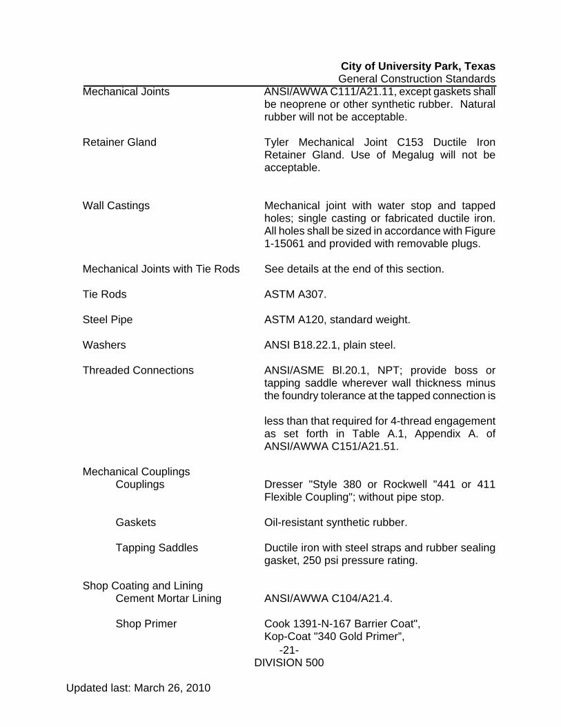
City of University Park, Texas General Construction Standards
-21- Updated last: March 26, 2010
DIVISION 500
Mechanical Joints ANSI/AWWA C111/A21.11, except gaskets shall be neoprene or other synthetic rubber. Natural rubber will not be acceptable.
Retainer Gland Tyler Mechanical Joint C153 Ductile Iron
Retainer Gland. Use of Megalug will not be acceptable.
Wall Castings Mechanical joint with water stop and tapped
holes; single casting or fabricated ductile iron. All holes shall be sized in accordance with Figure 1-15061 and provided with removable plugs.
Mechanical Joints with Tie Rods See details at the end of this section. Tie Rods ASTM A307. Steel Pipe ASTM A120, standard weight. Washers ANSI B18.22.1, plain steel. Threaded Connections ANSI/ASME Bl.20.1, NPT; provide boss or
tapping saddle wherever wall thickness minus the foundry tolerance at the tapped connection is
less than that required for 4-thread engagement
as set forth in Table A.1, Appendix A. of ANSI/AWWA C151/A21.51.
Mechanical Couplings
Couplings Dresser "Style 380 or Rockwell "441 or 411 Flexible Coupling"; without pipe stop.
Gaskets Oil-resistant synthetic rubber. Tapping Saddles Ductile iron with steel straps and rubber sealing
gasket, 250 psi pressure rating.
Shop Coating and Lining Cement Mortar Lining ANSI/AWWA C104/A21.4. Shop Primer Cook 1391-N-167 Barrier Coat", Kop-Coat "340 Gold Primer”,

City of University Park, Texas General Construction Standards
-22- Updated last: March 26, 2010
DIVISION 500
Tnemec "37-77 Chem-Prime", or Valspar "13-R-28 Chromox Primer”.
Asphaltic Coating Manufacturer's standard. Liquid Epoxy AWWA C210. Protective Fusion-Bonded Epoxy ANSI/AWWA C116/A21.16 Rust-Preventive Houghton "Rust Veto 344" or Compound Rust- Oleum "R-9". Coal Tar Coating Thixotropic coal tar, MIL-C-18480; Kop-Coat
"Bitumastic No. 50" or Tnemec "46-450 Heavy Tnemecol".
Polyethylene Encasement Materials Polyethylene film for encasement of pipe shall be
in accordance with ANSI/AWWA C105 / A21.5-82. Polyethylene tubing shall be of the seamless type. Joint tape shall be PVC or polyethylene, self-sticking type, 10 mils thick. The joint tape shall be Chase "Chasekote 750”,
Kendall "Polyken 900”, or 3M "Scotchrap 50".
Strapping shall be the non-metallic, water resistant type, conforming to Fed. Spec. PPP-S-760, Type II.
Gate Valves
Manufacturer/Model American-Darling All sizes Mueller All sizes M&H All sizes Clow All sizes
Butterfly Valves Manufacturer/Model American-Darling All sizes DeZurik All sizes M&H 14 inch and larger Mueller 12 inch and larger Pratt All sizes
Fire Hydrants

City of University Park, Texas General Construction Standards
-23- Updated last: March 26, 2010
DIVISION 500
Manufacturer/Model Mueller
Clow Shop Coating and Lining. The interior of all pipe and fittings for water service shall be cement mortar lined. The exterior surfaces of all pipe and fittings which will be exposed in interior locations shall be shop primed. Flange faces shall be coated with rust-preventive compound. Exterior surfaces of all other pipe and fittings shall be asphaltic coated. 506.3.1 LAYING WATER CONDUIT. Care and precautions shall be taken to prevent the introduction of foreign material into the existing system. Well fitted stoppers or bulkheads shall be securely placed in all openings and in the end of the line when construction is stopped temporarily and at the end of each day's work. It shall be the responsibility of the Contractor to deliver to the Engineer a pipeline which is clean throughout its entire length. Pipe, fittings, and accessories shall be handled in a manner that will ensure installation in sound, undamaged condition. Equipment, tools, and methods used in handling and installing pipe and fittings shall not damage the pipe and fittings. Hooks inserted in ends of pipe shall have broad, well-padded contact surfaces. Pipe and fittings in which the lining has been damaged shall be replaced. With the concurrence of the Engineer, small and readily accessible damaged areas may be repaired. All pipe coating which has been damaged shall be repaired by the Contractor before the pipe is installed. Bell holes of ample size shall be cut under and around all joints to provide adequate room for making joints and to assure that the barrel of the pipe rests uniformly and in continuous contact with the supporting ground for its entire length. Cutting shall be done in a neat manner, without damage to the pipe or the lining. Cuts shall be smooth, straight, and at right angles to the pipe axis. Ends of ductile iron pipe shall be cut with a portable guillotine saw, abrasive wheel, saw, milling cutter, or oxyacetylene torch. The use of hydraulic squeeze type cutters will not be permitted. Field-cut holes for saddles shall be cut with mechanical cutters; oxyacetylene cutting will not be permitted. After cutting, the end of the pipe shall be dressed with a file or power grinder to remove all roughness and sharp edges. The cut ends of push-on joint pipe shall be suitably beveled. The interior of all pipe and fittings shall be thoroughly cleaned of all foreign matter prior to installation and shall be kept clean until the work has been accepted. Before jointing, all joint contact surfaces shall be wire brushed if necessary, wiped clean, and kept clean until jointing is completed. Pipe and fittings shall be carefully examined for cracks and other defects immediately before installation; spigot ends shall be examined with particular care. All defective pipe and fittings shall be removed from the site of the work.

City of University Park, Texas General Construction Standards
-24- Updated last: March 26, 2010
DIVISION 500
Piping shall be laid to the lines and grades indicated on the drawings. Pipelines or runs intended to be straight shall be laid straight. Each pipe, fitting, and valve shall be lowered into the trench carefully and laid true to line and grade. All joints shall be made in strict accordance with the manufacturer's specifications. Either shorter pipe sections or fittings shall be installed where required to conform to the alignment or grade indicated on the drawings. A tolerance of three (3) inches from the established grade may be permitted, if approved by the Engineer, in order to prevent excessive breaks in alignment at the joints to such an extent that the joints cannot be properly made. Should conflict in grade occur with other utilities, the water line grade shall be changed to avoid the conflict. Precautions shall be taken to prevent foreign material from entering the pipe or existing system during installation. Debris, tools, clothing, or other materials shall not be placed in or allowed to enter the pipe. Water will not be permitted in the trenches while the pipe is being laid. The Contractor shall not open up more trenches than the available pumping facilities are able to dewater to the satisfaction of the Engineer. In areas where the water mains have been backfilled, the Contractor shall clear the right-of-way and surrounding ground, and shall dispose of all waste materials and debris resulting from his operations. He shall fill and smooth over holes and ruts and shall repair all miscellaneous and unclassified ground damage done by him, and shall restore the ground to such stable and usable conditions as may reasonable be required, consistent with the condition of the ground prior to the laying of the pipeline. Valves over 16 in. in diameter shall be installed in a special vault, or the gear box shall be enclosed in a manhole and supported on a concrete pad. Smaller valves shall be supported with concrete, all as detailed in appurtenance sheets attached to the plans. Protecting Public Water Supply. Water lines and sanitary sewers shall be installed no closer to each other than nine feet between outside diameters. Where this cannot be achieved. the sanitary sewer shall be constructed in accordance with § 317.13 of the Texas Administrative Code, Title 30 Environmental Quality (TAC) (relating to Appendix E-Separation Distances) and §290.44(e)(I) of TAC (relating to the Water Sources). Separation distances between sanitary sewer systems and water wells, springs, surface water sources and water storage facilities shall be installed in accordance with the requirements of §§290.41(c)(l), (d)(l), (e)(l)(C), (3)(A), and §290.43(b)(3) of TAC (relating to Water Storage), as appropriate. Where rules governing separation distance are in conflict, the most strict rule shall apply. No physical connection shall be made between a drinking water supply, public or private, and a sewer or any appurtenance. An air gap of a minimum of 18 inches or two pipe diameters, whichever is greater, shall be maintained between all potable water outlets and the maximum water surface elevation of sewer appurtenances. All appurtenances shall be designed and constructed so as to prevent any possibility of sewage entering the potable water system.

City of University Park, Texas General Construction Standards
-25- Updated last: March 26, 2010
DIVISION 500
Water Service Interruption. Water service, except when actually connecting or disconnecting meters or when making a water line tie-in, shall not be interrupted for any reason. The Contractor shall be responsible for maintaining adequate water service for the duration of the replacement project. The Contractor shall give written notices to residences and businesses that will be affected by the work, 24 hours in advance of the replacement of any utilities that may cause interruption to service regardless of the length of interruption. The notice shall include the approximate time construction is to begin and the estimated length of the anticipated interruption. Where a change in the size of the pipe occurs in the line, the measurement shall be to the center of the fitting. Where a change in the size of the pipe occurs in line, the measurement shall be to the center of the reducer. Conduits shall not be classified for payment according to the depth of the cut. Temporary Supply Mains, Service Lines. A temporary main of 3" Yelomine PVC Pipe Class 250 shall be installed on each side of the alley as required. The temporary mains shall be fed from existing water mains as approved by the Engineer. All fittings shall be lock or thread. Glued fittings shall not be permitted. Valves shall be furnished and installed by the Contractor on each temporary main at locations designated by the City, so that each temporary main can be shut off independently. The maximum distance between valves shall be 600’. One inch (1") blow-off coppers shall be installed at the end of each temporary water main. Cold mix asphalt shall be used to mount over the 3" temporary main at all driveways and crossing points, and at the locations where the 3" main crosses the street. The cold mix asphalt shall be removed after removal of the temporary main and the street cleaned. Tapping sleeves, crosses and valves shall be of standard manufacture and mechanical joint type to fit AWWA pipe specifications in Classes A, B, C and D. Tapping sleeves and crosses shall be designed for minimum working pressure of 200 pounds per square inch. Connecting flanges on tapping sleeves, crosses and valves shall be ASA Class 125. Tapping valves shall be designed for minimum working pressure of 200 pounds per square inch. All taps and fittings shall be lock or thread. Glued fittings shall not be permitted. Temporary Services: The Contractor shall furnish and place a temporary water service from the temporary main to the meter for each customer service line, consisting of a service clamp, corporation cock, and sufficient length of pipe to reach the meter. Temporary connections shall be made to existing service lines, using fittings as required. Temporary service lines shall match the size of existing service but no larger than 2 inches. It shall be the Contractor’s complete responsibility to assure that all temporary supply mains and service lines are adequately sterilized before putting into service. Temporary services must be installed and in service prior to excavation of pavement. When new main, services and curb stops have been installed, and testing and sterilization procedures completed, the Contractor shall connect the service from each house or business to meters as specified. It shall be the Contractor’s entire responsibility to maintain water service to

City of University Park, Texas General Construction Standards
-26- Updated last: March 26, 2010
DIVISION 500
customers at all times except during short periods when permanent and temporary lines are being connected and/or disconnected, and for final test. Each customer shall be given at least 24 hours notice before service is interrupted, delineating the clock time when it can be expected to be stopped and resumed. During cold weather, it shall be the Contractor’s responsibility to protect temporary mains and services from freezing by wrapping, covering, or maintaining flow in each pipe. Removal of existing water mains and appurtenances. All ferrous, copper or brass materials, pipe, pipe fittings, valves, meter boxes and covers, and services removed from existing installation shall be hauled by the Contractor to the Peek Service Center at 4419 Worcola, where it shall be off-loaded and placed by the Contractor at locations designated by the City. All such items remain the property of the City. Removal of existing water mains, fittings, valves, services and appurtenances shall be incidental to installation of replacement water conduits and appurtenances, and the costs of removal shall be included in the unit price named for those pay items in the Contract. Measurement and Payment. Temporary supply mains shall be measured and paid for at the contract price per linear foot, in accordance with size, type and class of pipe, complete in place, as provided in the proposal and contract. Connections to temporary water mains shall be measured as units per each, in accordance with size of connection, complete in place, as provided in the proposal and contract. Reducers, tees, valves, incidentals, and piping shall be included in the contract unit price for connections, and shall not be measured separately. The contract price for temporary supply mains, services, and connections shall be the total compensation for the furnishing of all labor, materials, tools, equipment and incidentals necessary to complete the Work. No separate measurement shall be made of any subsidiary items, such as bedding, fittings, accessories, excavation, trenching, backfilling, or any other items required for the completed installation of temporary water mains, services, and connections. Casing Pipe. Casing shall be as specified on the drawings. Grout shall be used to fill voids between the casing pipe and the surrounding soil on all bores and wherever else indicated on the plans. Grout shall also be placed between the carrier and casing pipes. Mix design shall be submitted to Engineer for approval prior to installation Measurement and Payment. Casing pipe shall be measured and paid for at the contract unit price per linear foot of encasement pipe installed, complete and in place, including furnishing and placing all materials including encasement pipe, grout backfill, sheeting, shoring, bracing, drainage, excavation and backfill, labor, tools, equipment, and any incidentals necessary to complete the work according to the drawings and these specifications. Plugging Pipes and Conduits. This work shall consist of plugging pipes and conduits as shown on the plans or in a manner approved by the Engineer. Pipes and Conduits to Remain in Service. Install bulkheads using Class B 2000 psi concrete, cast iron plugs or cast iron caps at cap ends of cut mains as shown. Place concrete blocking to bear between cap on line main and solid earth.

City of University Park, Texas General Construction Standards
-27- Updated last: March 26, 2010
DIVISION 500
Pipes and Conduits to be Abandoned. For water mains to be abandoned, construct bulkheads of Class B 2000 psi concrete, minimum one pipe diameter thick at cut ends. Measurement and Payment. Where plugs are classified separately as contract pay items, payment shall be made in accordance with the contract unit price per each, complete in place, as provided in the contract. The price shall be total compensation for furnishing all labor, materials, tools, equipment and incidentals necessary to complete the work, including all excavation, disposal of surplus material and backfill, all in accordance with the plans and specifications. Dewatering. The Contractor shall at all times during construction, provide and maintain ample means and devices with which to promptly remove and properly dispose of all water entering the water trenches or excavations, and keep said excavations dry until the structures are poured and the concrete has set. No pipes shall be laid, nor pipe joints made, in water; nor shall water be allowed to rise over masonry or mortar until the concrete or mortar has set at least twenty-four (24) hours. Blocking. Class B 2000 psi concrete shall be placed for blocking at each change in direction of all pressure pipelines in such manner as will substantially brace the pipe against undisturbed trench walls. Concrete blocking, made from Type I concrete, shall have been in place four (4) days prior to testing the pipeline as hereinafter specified. Test may be made in two (2) days after completion of blocking if Type III cement is used. No “Quikrete” allowed. Trenches underneath slabs and footing of structures shall be backfilled with flowable fill mixture unless otherwise shown on the plans. At all points where wet connections are made to existing lines, the tapping connection fittings shall be supported by blocking up to the spring line with 3000 psi concrete. All valves shall be supported by a 3000 psi concrete pad, 6 inches thick and of sufficient size to rest against undisturbed earth. Polyethylene Wrap for Ductile Iron Pipe and Fittings. Wrap all ductile iron pipe, water services, and fittings with polyethylene film conforming to the following specifications: The polyethylene film shall be 8 mils thick, with the following minimum flat tube widths for the specified pipe sizes. The polyethylene film shall be extracted from polyethylene resin, Type 1, Class C, Grade E-1, and as specified in ASTM D-1248, with the following characteristics:
Flow rate - 0.4 maximum Tensile Strength - 1200 PSI minimum Elongation - 300% minimum Dielectric Strength - Volume Resistivity, minimum ohm - cm3 800 volts per mil thickness minimum
The polyethylene tube seams and overlaps shall be wrapped and held in place by means of 2-inch wide plastic backed adhesive tape 10 mils thick. The tape shall be Polyken No.900, Scotchwrap No.50 , or approved equivalent. The spigot end of the pipe should be elevated, clay and debris brushed away,

City of University Park, Texas General Construction Standards
-28- Updated last: March 26, 2010
DIVISION 500
and 20 feet of film slipped over the pipe (if 18' joint being laid, if less, provide a 2' lap). Wrap the film tightly around the spigot end, leaving about 4 to 5 inches clear, and tape the edge down lightly with 3-inch polyethylene adhesive tape. Lifting of pipe for installation shall be with a nylon rope and not a steel chain. When the pipe is picked up for transport to the ditch, clear the rest of the pipe of clay and debris. Insert the spigot end into the bell and push home and release the pipe into the ditch. Pick up the pipe at bell and slide the film to a point back of the bell and prepare a bell hold. When the next joint is laid, pull the film about 2 feet beyond the bell, overlapping the film attached to the spigot of the new pipe joint. Wrap the film with tape according to manufacturer’s specifications. Fitting, valves and boxes, hydrants or other ferrous metal appurtenances installed with non-ferrous pipe shall be wrapped; the film sheath shall be extended two feet (2') onto the adjoining non-ferrous pipe, with some slack left in its length, and the end taped to the pipe barrel. Hand-bind the pipe in place to prevent damage during backfill. Tamp on each side carefully to prevent damage to the film. Measurement and Payment. Payment for concrete blocking shall be made only if a separate bid item is established in the contract. If a separate bid item is not established, this item shall be included in the price of the pipe bid item. Conduit, including corrosion protection in place on the conduit, shall be paid for at the contract unit price per linear foot, completed in place, as provided by the proposal and contract. The contract price per linear foot shall be the total compensation for the furnishing of all labor, materials, tools, equipment and incidentals necessary to complete the work, including excavations, backfill, and disposal of surplus materials, in accordance with the plans and these specifications. Removal of any existing utility lines (shown on the drawings to be abandoned), due to proximity to a proposed water line, shall be subsidiary to the price of the new water line. 506.4 PIPE JOINTS. Rubber Gasket Joints. Gaskets shall be neoprene or other synthetic rubber. Natural rubber will not be acceptable. Mechanical Joints. Mechanical joints shall be carefully assembled in accordance with the manufacturer's recommendations. If effective sealing is not obtained, the joint shall be disassembled, thoroughly cleaned, and reassembled. Bolts shall be uniformly tightened to the torque values listed in Appendix A of ANSI/AWWA Clll/A21.11. Over tightening of bolts to compensate for poor installation practice will not be permitted. The holes in mechanical joints with tie rods shall be carefully aligned to permit installation of the tie rods. In flange and mechanical joint pieces, holes in the mechanical joint bells and the flanges shall straddle the top (or side for vertical piping) center line. The top (or side) center line shall be marked on each flange and mechanical joint piece at the foundry. Push-on Joints. The pipe manufacturer's instructions and recommendations for

City of University Park, Texas General Construction Standards
-29- Updated last: March 26, 2010
DIVISION 500
proper jointing operations shall be followed. All joint surfaces shall be lubricated with heavy vegetable soap solution immediately before the joint is completed. Lubricant shall be suitable for use in potable water, shall be stored in closed containers, and shall be kept clean. Each spigot end shall be suitably beveled to facilitate assembly. Pipe ends for restrained joint pipe shall be prepared in accordance with the pipe manufacturer's recommendations. Flanged Joints. Pipe shall extend completely through screwed-on flanges. The pipe end and flange face shall be finish machined in a single operation. Flange faces shall be flat and perpendicular to the pipe center line. When bolting flanged joints, care shall be taken to avoid restraint on the opposite end of the pipe or fitting which would prevent uniform gasket compression or which would cause unnecessary stress in the flanges. One flange shall be free to move in any direction while the flange bolts are being tightened. Bolts shall be tightened gradually and at a uniform rate, to ensure uniform compression of the gasket. Mechanical Couplings. Mechanical couplings shall be carefully installed in accordance with the manufacturer's recommendations. A space of at least 1/4 inch and not more than one inch shall be left between the pipe ends. Pipe and coupling surfaces which contact gaskets shall be clean and free from dirt and other foreign matter during assembly. All assembly bolts shall be uniformly tightened so that the coupling is free from leaks and all parts of the coupling are square and symmetrical with the pipe. Following installation of the coupling, damaged areas of shop coatings on the pipe and coupling shall be repaired to the satisfaction of the Engineer. The interior surfaces of the middle rings shall be prepared for painting in accordance with instructions of the paint manufacturer and shall then be coated with liquid epoxy in accordance with AWWA C210. The remaining components shall be cleaned and shop primed with the manufacturer's standard rust-inhibitive primer. Wall Castings. Unless otherwise indicated on the drawings, wall castings shall be provided where ductile iron pipes pass through concrete walls. Where a flange and mechanical joint piece is to connect to a mechanical joint wall casting, the bolt holes in the bell of the wall casting shall straddle the top (or side for vertical piping) center line of the casting and shall align with the bolt holes in the flange and mechanical joint piece. The top center line shall be marked on the wall casting at the foundry. Fittings. Cut-in sleeves are to be used on all tie-ins and/or pipe connections. Measurement and Payment. Payment for fittings, adapters, couplings, and wall castings shall be made only if a separate bid item is established in the contract. If a separate bid item is not established, these items shall be included in the price of the pipe bid item. The contract price per linear foot shall be the total compensation for the furnishing of all labor, materials, tools, equipment and incidentals necessary to complete the work, including excavations, backfill, and disposal of surplus materials, in accordance with the plans and these specifications. 506.5 HYDROSTATIC TEST.
City of University Park, Texas General Construction Standards
-30- Updated last: March 26, 2010
DIVISION 500
Before being accepted, all newly laid pipe, or any valve section thereof shall be tested, per NTCOG specification, with a hydraulic test pressure of not less than 150 psi, maintained over a period of not less than 4 hours or a hydraulic test pressure of not less than 200 psi, maintained over a period of not less than 2 hours, unless otherwise specified by the Engineer. The Engineer shall determine the testing pressure and duration of test required. A representative from the City’s Water Department shall be present during the hydrostatic test. Prior to pressure testing the line, the line must have been flushed completely, to the satisfaction of the Engineer. The pipe shall be filled with water, care being exercised to expel all air from the pipe. During the test period, pipe, valves, meter, fittings, and joints shall be carefully examined for defects. The gauge shall be located at the lowest point in the system to be tested. If the line cannot be tested at its lowest point, a correction factor of minus 0.43 lb./vert. ft. shall be made. As a minimum, the following equipment will be required for such test:
Pump that will produce 200 psi with no leaks in pump or piping. 5/8 meter (water). Pressure regulator 0 to 250 psi.
The rate of leakage of all pipe tested shall not exceed 11.65 gallons per inch of nominal diameter of pipe per mile (0.01 cu. m. per cm. of nominal diameter per km.) over a 24 hour period. Water lines of materials in combination shall be tested for the type of pipe (material) with the least stringent hydraulic test pressure maintained over a period of not less than 4 hours. Refer to the provided table, "Allowable Leakage for 4 Hours at Test Pressure of 150 PSI," to determine acceptable test values. Any observed leaks or defective pipe, pipe joints, fittings, and appurtenances (even if the test requirements are met) shall be satisfactorily repaired or replaced at the expense of the Contractor and the test repeated until the section under test is within the limits prescribed. Allowance for valve leakage to the atmosphere may be determined as no more than 0.0078 gal./hr./in. of nominal valve size. The Engineer cannot guarantee that an old existing system valve shall hold the required pressure. Care shall be taken to insure that water mains existing prior to this contract are not pressure tested. Any old mains damaged by pressure testing shall be repaired at the expense of the Contractor. The Contractor has the option of plugging the new main prior to tying onto the existing system and testing against the old valve. If the old valve does not hold against the test pressure, then the Contractor must cut and plug the new main, hydrostatic test the new main, and then complete the tie-in.

City of University Park, Texas General Construction Standards
-31- Updated last: March 26, 2010
DIVISION 500
ALLOWABLE LEAKAGE (GALS.) FOR 4 HOURS AT TEST PRESSURE OF 150 PSI Length Pipe Size (Ft.) (Inches)
6 8 10 12 14 16 18 20 24 30 36 42 48 54 60 66 5 0.01 0.01 0.02 0.02 0.03 0.03 0.03 0.04 0.04 0.06 0.07 0.08 0.09 0.10 0.11 0.12 10 0.02 0.03 0.04 0.04 0.05 0.06 0.07 0.07 0.09 0.11 0.13 0.15 0.18 0.20 0.22 0.24 15 0.03 0.04 0.06 0.07 0.08 0.09 0.10 0.11 0.13 0.17 0.20 0.23 0.26 0.30 0.33 0.36 20 0.04 0.06 0.07 0.09 0.10 0.12 0.13 0.15 0.18 0.22 0.26 0.31 0.35 0.40 0.44 0.49 25 0.06 0.07 0.09 0.11 0.13 0.15 0.17 0.18 0.22 0.28 0.33 0.39 0.44 0.50 0.55 0.61 50 0.11 0.15 0.18 0.22 0.26 0.29 0.33 0.37 0.44 0.55 0.66 0.77 0.88 0.99 1.10 1.21 75 0.17 0.22 0.28 0.33 0.39 0.44 0.50 0.55 0.66 0.83 0.99 1.16 1.32 1.49 1.66 1.82 100 0.22 0.29 0.37 0.44 0.51 0.59 0.66 0.74 0.88 1.10 1.32 1.54 1.77 1.99 2.21 2.43 200 0.44 0.59 0.74 0.88 1.03 1.18 1.32 1.47 1.77 2.21 2.65 3.09 3.53 3.97 4.41 4.85 300 0.66 0.88 1.10 1.32 1.54 1.77 1.99 2.21 2.65 3.31 3.97 4.63 5.30 5.96 6.62 7.28 400 0.88 1.18 1.47 1.77 2.06 2.35 2.65 2.94 3.53 4.41 5.30 6.18 7.06 7.94 8.83 9.71 500 1.10 1.47 1.84 2.21 2.57 2.94 3.31 3.68 4.41 5.52 6.62 7.72 8.83 9.93 11.03 12.14 600 1.32 1.77 2.21 2.65 3.09 3.53 3.97 4.41 5.30 6.62 7.94 9.27 10.59 11.92 13.24 14.56 700 1.54 2.06 2.57 3.09 3.60 4.12 4.63 5.15 6.18 7.72 9.27 10.81 12.36 13.90 15.45 16.99 800 1.77 2.35 2.94 3.53 4.12 4.71 5.30 5.88 7.06 8.83 10.59 12.36 14.12 15.89 17.65 19.42 900 1.99 2.65 3.31 3.97 4.63 5.30 5.96 6.62 7.94 9.93 11.92 13.90 15.89 17.87 19.86 21.85 1000 2.21 2.94 3.68 4.41 5.15 5.88 6.62 7.36 8.83 11.03 13.24 15.45 17.65 19.86 22.07 24.27 Valve 0.19 0.25 0.31 0.37 0.44 0.50 0.56 0.62 0.75 0.94 1.12 1.31 1.50 1.68 1.87 2.06 Allowable Leakage (Gals.) for 4 hours
SD P / 133,200 = x 4
S = Length of Pipe, Ft. Valve Leakage Allowable = 0.0078 Gal./Hour/In. of nominal valve size D = Diameter of Pipe, In. Test - Ductile Iron and Plastic at 150 psi P = 150 psi Height Correction = 0.43 psi/Ft.
The Contractor shall provide all necessary pumping equipment, piping connections between the piping and the nearest available source of test water, pressure gauges, and other equipment, materials, and facilities necessary for the tests. The cost of testing and repairing the leaks, including all uncovering, repairing, backfilling and incidental work, shall be at the expense of the Contractor. All testing shall be performed in the presence of the Engineer. Testing

City of University Park, Texas General Construction Standards
-32- Updated last: March 26, 2010
DIVISION 500
operations shall remain in operation until approved by the Engineer. Allowable leakage shall not exceed 11.65 gallons of water per day per mile of pipe per inch of nominal diameter, for pipe in 18 foot lengths evaluated at a pressure of 150 psi or AWWA C600, Section 13, whichever is greater. Leakage shall be measured by an approved calibrated meter through which all of the water required to maintain test pressure is pumped. Joints for fire hydrants and valves shall be considered. 506.6 CONNECTIONS TO EXISTING WATER MAINS All such connections shall be made at such times and in a manner that will be agreeable to the city utilities department. Where connections are to be made to existing mains under pressure and it shall be possible to valve off the section of existing main where the connection is to be made, the Contractor may have the option of either connecting by means of tapping connection fittings suitable for the conditions or by cutting the main and using standard fittings. Facilities shall be provided for proper dewatering and for disposal of all water removed from the dewatered lines and excavations without damage to adjacent property. Tapping sleeves, crosses and valves shall be of standard manufacture and mechanical joint type to fit AWWA pipe specifications in Classes A, B, C and D. Tapping sleeves shall only be allowed on existing mains that are intended to be abandoned upon completion of the Work. Special care shall be taken to prevent contamination when dewatering, cutting into, and making connections with existing potable water piping. Trench water, mud, or other contaminating substances shall not be permitted to enter the lines. The interior of all pipe, fittings, and valves installed in such connections shall be thoroughly cleaned and then swabbed with, or dipped in, chlorine solution having a chlorine content of 200 milligrams per liter. Measurement and Payment. No separate measurement shall be made of any subsidiary items, such as thrust blocking, poly wrapping, bedding, fittings, accessories, excavation, trenching, backfilling, or any other items required for the completed installation of the water lines. Connections to existing water mains shall be measured as units per each under connections when specified on the plans to be a separate pay item. Reducers, tees, valves, incidentals, and piping shall be included in the contract unit price for connections, and shall not be measured separately. 506.7 PURGING AND DISINFECTION OF WATER CONDUITS Flushing of Water Mains. Before temporary water mains and all newly constructed water mains shall be permitted to be placed into service, they shall be flushed by the Contractor. All water mains shall be flushed prior to pressure testing. A representative from the City’s Water Department shall be present during the flushing of the new line. The requirements for flushing are as follows: retain a minimum velocity of 2.5 feet per second until a volume of 5 times the capacity of the water main is flushed or until the discharge is free of any debris or turbidity. The following are gallon per minute requirements for specific pipe sizes for a minimum flow for a velocity of 2.5 feet per
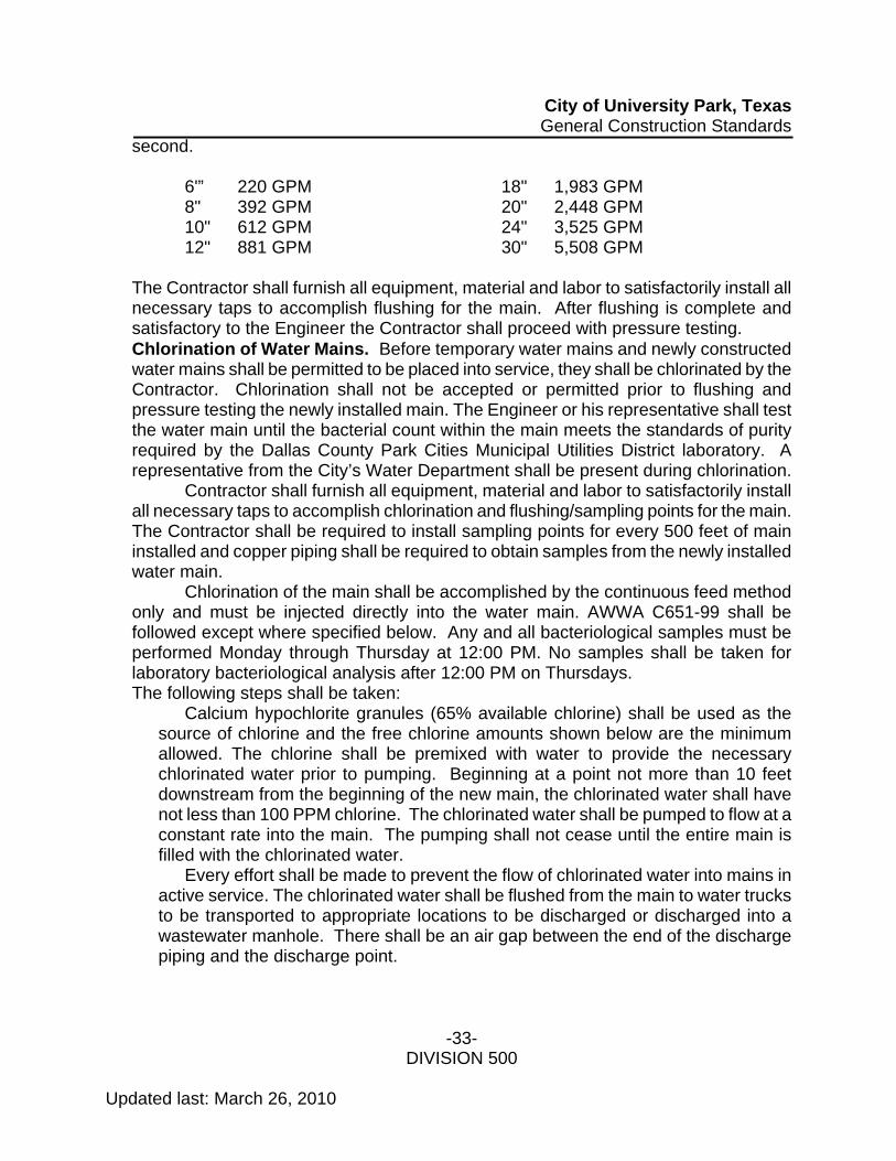
City of University Park, Texas General Construction Standards
-33- Updated last: March 26, 2010
DIVISION 500
second. 6'” 220 GPM 18" 1,983 GPM 8" 392 GPM 20" 2,448 GPM 10" 612 GPM 24" 3,525 GPM 12" 881 GPM 30" 5,508 GPM
The Contractor shall furnish all equipment, material and labor to satisfactorily install all necessary taps to accomplish flushing for the main. After flushing is complete and satisfactory to the Engineer the Contractor shall proceed with pressure testing. Chlorination of Water Mains. Before temporary water mains and newly constructed water mains shall be permitted to be placed into service, they shall be chlorinated by the Contractor. Chlorination shall not be accepted or permitted prior to flushing and pressure testing the newly installed main. The Engineer or his representative shall test the water main until the bacterial count within the main meets the standards of purity required by the Dallas County Park Cities Municipal Utilities District laboratory. A representative from the City’s Water Department shall be present during chlorination. Contractor shall furnish all equipment, material and labor to satisfactorily install all necessary taps to accomplish chlorination and flushing/sampling points for the main. The Contractor shall be required to install sampling points for every 500 feet of main installed and copper piping shall be required to obtain samples from the newly installed water main. Chlorination of the main shall be accomplished by the continuous feed method only and must be injected directly into the water main. AWWA C651-99 shall be followed except where specified below. Any and all bacteriological samples must be performed Monday through Thursday at 12:00 PM. No samples shall be taken for laboratory bacteriological analysis after 12:00 PM on Thursdays. The following steps shall be taken:
Calcium hypochlorite granules (65% available chlorine) shall be used as the source of chlorine and the free chlorine amounts shown below are the minimum allowed. The chlorine shall be premixed with water to provide the necessary chlorinated water prior to pumping. Beginning at a point not more than 10 feet downstream from the beginning of the new main, the chlorinated water shall have not less than 100 PPM chlorine. The chlorinated water shall be pumped to flow at a constant rate into the main. The pumping shall not cease until the entire main is filled with the chlorinated water.
Every effort shall be made to prevent the flow of chlorinated water into mains in active service. The chlorinated water shall be flushed from the main to water trucks to be transported to appropriate locations to be discharged or discharged into a wastewater manhole. There shall be an air gap between the end of the discharge piping and the discharge point.

City of University Park, Texas General Construction Standards
-34- Updated last: March 26, 2010
DIVISION 500
Chlorine Required to Produce 25-mg/L Concentration in 100 ft of Pipe by Diameter
Pipe Diameter 65% Chlorine 100% Chlorine inches lb lb
6 0.046 0.030 8 0.083 0.054 10 0.131 0.085 12 0.185 0.120 16 0.334 0.217
Table taken from AWWA C651-99, p.10, Table 4 The Engineer or his representative shall perform the laboratory analysis. If the tests show a satisfactory quality of water, the line may be placed in service. Unsatisfactory test results shall require rechlorination and flushing of the water main until an acceptable sample is obtained at all sample sites. Upon satisfactory completion of the chlorination and testing, the Contractor shall remove piping and fittings used for the chlorination and sampling points, down to the corporation stop, backfill leaving the corporation stop in place, and complete all appurtenant work necessary to restore the area to its original condition. The Contractor’s removal of the chlorination and sampling points shall include all labor, materials, tools, equipment and incidentals necessary to complete the work, including excavation, backfill, compaction, and disposal of surplus materials without additional compensation. 507 OPEN CUT – WASTEWATER CONDUIT INSTALLTION 507.1 DESCRIPTION. This section covers solid wall polyvinyl chloride (PVC) low pressure, gravity sewer pipe and fittings to be furnished complete with all jointing materials and appurtenances. Pipe shall be installed and tested in accordance with the sewer pipe installation and testing section. Pipe or fittings having either spiral or concentric external reinforcing ribs will not be acceptable. All DWV pipe and/or fittings shall not be acceptable. The Contractor shall field verify all "end of the main services for location and elevations" prior to beginning construction for that portion of the sanitary sewer main. 507.2 MATERIALS. Where specified on the plans, sanitary sewer pipe shall be polyvinyl chloride SDR-26 Class 160 IPS with pressure rated fittings. All pipe for sanitary sewer laterals shall have push-on gasket joints. No glued joints shall be used on sanitary sewer mains or services to the property line. The transition from pressure rated pipe to non or low pressure pipe shall occur at the property line.

City of University Park, Texas General Construction Standards
-35- Updated last: March 26, 2010
DIVISION 500
SDR 35 Sewer Pipe 4 Inch Through 15 Inch ASTM D3034, Cell Classification
ASTM D1784 12454-B or 12454-C or 13364-B 18 Inch and greater ASTM F679, Type T-1A and Type T-2B SDR 35 Sewer Pipe Fittings 4 Inch Through 15 Inch ASTM D3034, Cell Classification
ASTM D1784 12454-B or 12454-C or 13343-C
18 Inch and greater ASTM F679, Type T-1A and Type T-2B Bell-and-Spigot Joints ASTM D3212, integral bell push-on type elastomeric gasket joints. Gaskets ASTM F477 Field-Cut Joints and Fernco “Flexible Couplings", or Mission Connections to Other "Eastern Standard Band-Seal Couplings” Piping Materials with stainless steel shear rings. Eccentric Reducers 6" Eccentric rubber collar w/stainless steel Clay Tile to 4" PVC bands (DFW Plastics, Inc., No. DFW 02-E64 or
approved equal) For Grouted Connections to ASTM C-923, A-Lok Rubber gasket Precast Concrete Manholes SDR 26 Class 160 IPS Sewer Pipe (Pressure Rated Pipe) 4 Inch Through 36 Inch ASTM D2241, Cell Classification ASTM 1784 Size Determination 12454B, ASTM D2122. Bell-and-Spigot Joints ASTM D3139, integral bell push-on type elastomeric gaskets For Grouted Connections to ASTM C-923, A-Lok Rubber gasket or Cast-in-Place Concrete Manholes approved equal Laying Length 13 Feet unless approved by the City Engineer for the use of 20 foot lengths Gaskets ASTM F477, synthetic rubber. Natural rubber will not be acceptable.

City of University Park, Texas General Construction Standards
-36- Updated last: March 26, 2010
DIVISION 500
SDR 26 Class 160 and SDR 21 Class 200 IPS Sewer Pipe Fittings 4 Inch Through 36 Inch ASTM D1784, Cell Classification 12454B, Size Determination ASTM D2122. Gaskets ASTM F477, synthetic rubber.
Natural rubber will not be acceptable.
DR 25 Class 165 C.I.O.D. Pressure Sewer Pipe and Fittings 24 Inch Through 30 Inch AWWA Standard C905 Polyvinyl Chloride PVC
Water Transmission Pipe Size Determination ASTM D2122.
Bell-and-Spigot Joints ASTM D3139, integral bell push-on type elastomeric gaskets For Grouted Connections to ASTM C-923, A-Lok Rubber gasket or Cast-in-Place Concrete Manholes approved equal Laying Length 20' +/- 1" unless for all sizes Gaskets ASTM F477, synthetic rubber. Natural rubber will not be acceptable. Alignment. Sewers shall be laid in straight alignment with uniform grade between manholes. Drawings and Data. Drawings and data shall be submitted in accordance with the submittals section in Division 1. Drawings and data shall include, but not be limited to, the following:
Details of joints. Gasket material. Pipe length. Certification in accordance with the appropriate ASTM specification.
507.3 LAYING WASTEWATER CONDUIT. Well fitted stoppers or bulkheads shall be securely placed in all openings and in the end of the line when construction is stopped temporarily and at the end of each day's work. Water will not be permitted in the trenches while the pipe is being laid. The Contractor shall not open up more trenches than the available pumping facilities are able to dewater to the satisfaction of the Engineer. It shall be the responsibility of the Contractor to deliver to the Engineer a pipeline which is clean throughout its entire length.

City of University Park, Texas General Construction Standards
-37- Updated last: March 26, 2010
DIVISION 500
Bell holes of ample size shall be cut under and around all joints to provide adequate room for making joints and to assure that the barrel of the pipe rests uniformly and in continuous contact with the supporting ground for its entire length. Sanitary Sewer Overflow and Bypass Events. The Contractor shall promptly notify the City of University Park of any sanitary sewer overflow or sanitary sewer bypasses within the project limits. During such time, the Contractor shall, at his own expense, furnish all labor, materials, tools and equipment required and shall take such action to correct the problem and mitigate any adverse effects of the overflow or bypass. The Contractor shall assist the City in making any formal written reports to regulatory agencies for the event. Removal of Existing Sanitary Sewer Lines and Appurtenances. Sanitary sewer construction shall include the replacement of existing facility and shall require removal or abandonment of existing mains, manholes, and cleanouts as noted on the plans. Removal of any existing utility facility (shown on the drawings to be abandoned), due to proximity to a proposed sewer line, shall be subsidiary to the price of the new sewer line. It shall require disconnecting existing services, and placement of new sewer main, manholes, cleanouts and services, and reconnection of services with minimal interruption of sewage flow. Open flow of sewage in the trench, ground surface or discharge into any facility other than an operational sanitary sewer shall not be permitted. Existing Sewer Main (where required). Existing sewer mains shall be removed in lengths which permit complete removal and replacement of sewer mains and of materials within a maximum period of eight (8) hours, during which period flow from the upstream manhole and from affected house services shall be blocked by inflatable plugs and pumped into the downstream manhole. Bypass pumping shall be maintained until the last joint of pipe has been installed for that days production, after which a temporary night time tie-in connection for the proposed main and the existing main shall be installed. The sequence shall be repeated, starting at the downstream end of each length of sewer, until the upstream end is reached. Pumps required shall be of the type used for the complete removal of solids and for adequately maintaining a discharge rate equivalent to the flows entering the manholes. Flows from existing service laterals within the section of existing main being bypassed, shall be contained in the pipe trench and channelized into the downstream main. Materials so removed shall become the property of the Contractor and shall be legally disposed of by him. Existing Manholes. The Contractor shall dismantle, break up and otherwise demolish the existing structure and base. Manhole frames and covers shall remain the property of the Engineer and shall be delivered by the Contractor to the City’s Service Center at 4419 Worcola Street. Other materials removed shall become the property of the Contractor and shall be legally disposed of by him. Existing Sanitary Sewer Services. Existing sewer service laterals shall be removed by

City of University Park, Texas General Construction Standards
-38- Updated last: March 26, 2010
DIVISION 500
the Contractor to the alley right-of-way line to permit installation of new laterals. Removal items shall be legally disposed of by Contractor. New two-way single stack cleanouts shall be installed at property line. 507.5 TESTS AND INSPECTIONS. An infiltration/exfiltration or low-pressure air test, deflection test, and a television inspection shall be required. The City's inspector must be present during the testing and/or television inspection, unless otherwise authorized by the City. Copies of all test results shall be given to the Engineer or his designated representative. All testing and television inspections shall be subsidiary to various bid items. Testing and television inspection shall conform to the following requirements: Infiltration/Exfiltration Tests. The total exfiltration as determined by a hydrostatic head test, shall not exceed 50 gallons per inch diameter per mile of pipe per 24 hours at a minimum test head of two feet above the crown of the pipe at the upstream manhole. When pipes are installed below the groundwater level an infiltration test shall be used in lieu of the exfiltration test. The total infiltration, as determined by a hydrostatic head test, shall not exceed 50 gallons per inch diameter per mile of pipe per 24 hours at a minimum test head of two feet above the crown of the pipe at the upstream manhole, or at least two feet above existing groundwater level, whichever is greater. If the quantity of infiltration or exfiltration exceeds the maximum quantity specified, remedial action shall be undertaken in order to reduce the infiltration or exfiltration to an amount within the limits specified. 507.5.1.4 FLEXIBLE PIPE (DEFLECTION) TESTING. Deflection tests shall be performed on all flexible pipes. A rigid mandrel shall be used to measure deflection. No pipe shall exceed a deflection of 5.0%. If a pipe should fail to pass the deflection test, the problem shall be corrected and a second test shall be conducted after the final backfill has been in place an additional 30 days. 507.5.1.4.1 MANDREL. The rigid mandrel shall have an outside diameter (O.D.) equal to 95% of the inside diameter (I.D.) of the pipe. The inside diameter of the pipe, for the purpose of determining the outside diameter of the mandrel, shall be the average outside diameter minus two minimum wall thicknesses for O.D. controlled pipe and the average inside diameter for I.D. controlled pipe, all dimensions shall be per appropriate standard. Statistical or other "tolerance packages" shall not be considered in mandrel sizing. The rigid mandrel shall be constructed of a metal or a rigid plastic material that can withstand 200 psi without being deformed. The mandrel shall have nine or more "runners" or "legs" as long as the total number of legs is an odd number. The barrel section of the mandrel shall have a length of at least 75% of the inside diameter of the pipe. A proving ring shall be provided and used for each size mandrel in use. Adjustable or flexible mandrels are prohibited. A television inspection is not a

City of University Park, Texas General Construction Standards
-39- Updated last: March 26, 2010
DIVISION 500
substitute for the deflection test. A deflectometer may be approved for use on a case- by-case basis. Mandrels with removable legs or runners may be accepted on a case-by-case basis. 507.5.2 TELEVISION INSPECTION. MEASUREMENT AND PAYMENT. Testing by the Contractor shall be measured and paid for at the contract unit price per each, as provided in the proposal and contract. 507.5.2.3 CRITERIA FOR ACCEPTANCE OF TV-INSPECTED PIPE. Acceptance criteria also includes: water depth exceeding allowable standing water. 507.6 MEASUREMENT AND PAYMENT FOR WASTEWATER CONDUIT
INSTALLATION. Pipe shall be measured for payment in linear feet along the centerline of the pipe actually laid and paid for at the contract unit price per linear foot, complete in place, as provided by the contract. Deductions shall be made for special structures. Pipe which extends only through the wall of the structure shall be measured to the actual end of the pipe. No deductions shall be made for fittings, measurements being from center to center of fitting. Where a change in the size of the pipe occurs in the line, the measurement shall be to the center of the fitting. Where change in the size of the pipe occurs in the line, measurement shall be to the center of the reducer. Removal of any existing utility facility (shown on the drawings to be abandoned), due to proximity to a proposed sewer line, shall be subsidiary to the price of the new sewer line. Conduits shall not be classified for payment according to depth. The contract price per linear foot shall be the total compensation for furnishing of all labor, materials, tools, equipment, and incidentals necessary to complete the work, including excavations, backfill and disposal of surplus material, in accordance with the plans and these specifications.