part 6 superstructure (excluding roofs) chapter 6 · timber joists are built into solid external...
TRANSCRIPT

Chapter 6.4Timber and concrete upper floors
Part 6 Superstructure (excluding roofs)

6.4
6.4
Timber and concrete upper floors
CONTENTS
DESIGN Clause Page
Design standards D1 1
Statutory requirements D2 1
Upper floor design D3 1
Timber floor joists D4 1
Trimmer joists D5 2
Strutting of floor joists D6 2
Joist hangers D7-D8 2 - 3
Joist support at separating walls D9 3
Restraint strapping D10 3
Structural steel in floors D11 3
Fire spread D12-D13 3
Floor decking D14 4
Concrete floors D15 4
Floors between dwellings D16-D17 4
Provision of information D18-D19 4
MATERIALS
Materials standards M1 4
Timber floors M2-M4 4
Joist hangers and restraint straps M5 5
Strutting M6 5
Floor decking M7 5
Sound insulation M8 5
Structural steel in floors M9 5
Concrete and reinforcement M10 5
Proprietary systems M11 5
SITEWORK
Sitework standards S1 5
Timber floors S2 5
Joist hangers S3-S4 6
Trimmed and trimming joists S5-S6 6 - 7
Multiple joists S7 7
Strutting of floors S8 8
Notching and drilling S9 9
Restraint strapping S10-S12 9 - 10
Overlapping and butted joists S13 10
Floor decking: general S14-S16 10
Softwood boarding S17 11
Chipboard flooring S18-S19 11
Oriented strand board flooring S20 11
Plywood flooring S21 11
Other floor decking S22 12
Floors between dwellings S23 12
Concrete floors S24-S25 12
In-situ concrete S26 12
Precast concrete S27 12
Fire-stopping S28 13
APPENDIX 6.4-A
Span tables for timber floor joists 13
INDEX 16
SCOPE
This Chapter gives guidance on meeting the Technical Requirements and recommendations for the construction of timber and concrete upper floors.

6.4 6
.4
Page 1Chapter 6.4
Timber and concrete upper floors
2013
DESIGN STANDARDS
6.4 - D1 Design shall meet the Technical Requirements
Design that follows the guidance below will be acceptable for timber and concrete upper floors.
STATUTORY REQUIREMENTS6.4 - D2 Design shall comply with all relevant statutory requirements
Design should be in accordance with relevant Building Regulations and other statutory requirements.
UPPER FLOOR DESIGN6.4 - D3 Upper floors shall be designed to support and transmit loads safely to the supporting structure without undue deflection
Items to be taken into account include:
(a) dead and imposed loadsThe dead loads should include the weight of the following:
floor structure, decking and finishes• ceilings and applied finishes • walls and partitions supported by the • floorpermanent fixtures such as boilers, • watertanks, etc.
Imposed loads are the variable loads imposed when the building is in use. They include the weight of furniture and people. BS EN 1991-1-1 recommends an imposed loading allowance of 1.5kN/m2 for self contained dwellings.
Where the design includes communal areas serving flats or maisonettes, refer to BS EN 1991-1-1 for recommended imposed loads.
Information concerning balconies is given in Chapter 7.1 ‘Flat roofs and balconies’ (Design and Sitework).
(b) supporting structureThe floor structure should have an adequate bearing on the supporting structure. Timber joists should normally have a minimum bearing as shown in the table.
Type of timber joist
Minimum bearing [mm]
End support Intermediate support
Solid joist on masonry walls
90 (75) 90 (75)
Solid joist on timber wall plate
75 75
I-joist 90 (45) 90
Metal web joist 90 (75) 90
NoteFigures in brackets should only be used when the joist is not providing restraint to the wall.
I-joist
metal web
The support reaction due to dead and imposed loads on the floor should not exceed the recommended value specified by the manufacturers of I-joists and metal web joists.
Where necessary, I-joists should have web stiffeners at the locations of concentrated loads in accordance with the manufacturer’s recommendations.
webstiffeners
intermediate bearing end bearing
Metal web joists should have uprights at the supports between the flanges held in place by punched metal plate fasteners. Other support options are either top or bottom chord (flange) support, designed by the manufacturer.
uprights atend bearing
uprights atintermediate bearing
Joists may be supported on joist hangers or on internal load bearing walls. Where permitted they may be built into the inner leaf of an external cavity wall. Where joists are built into the inner leaf care should be taken to ensure air-tightness. Where solid timber joists are built into solid external walls, they should be pre-treated with preservative in accordance with Chapter 2.3 ‘Timber preservation (natural solid
timber)’ (Design). I-joists and metal web joists should not be built into solid external walls.
Concrete floors should normally have a minimum bearing of 90mm on masonry walls.
TIMBER FLOOR JOISTS6.4 - D4 Floor joists shall be adequate for the spans and imposed loads
Items to be taken into account include:
(a) designStructural timber for solid joists is normally specified as strength Class C16 or C24. Tables giving the permitted clear span for joists of strength Class C16 and C24 are given in the TRADA Technology Ltd publication “Span tables for solid timber members in floors, ceilings and roofs (excluding trussed rafter roofs) for dwellings” reproduced in Appendix 6.4-A.
I-joists and metal web joists should be specified in accordance with the manufacturer’s instructions and the following deflection limits based on total dead and imposed loads for combined bending and shear; 0.003 times the span with a maximum deflection of 14mm if strutting is provided or 12mm if strutting is not provided.
I-joists and metal web joists should not be used in situations where any part of the joist is exposed to external conditions.
(b) joist sizesSolid timber joist sizes are given in the span tables in BS 8103-3. Where the tables do not apply or where there are concentrated loads, floor joists should be designed by an Engineer in accordance with Technical Requirement R5.
Regularised timber is recommended for floor joists. The section sizes in the tables reproduced in Appendix 6.4-A should be regularised, or be ALS or CLS to enable floors and ceilings to be level.
I-joists and metal web joists should be specified in accordance with manufacturers’ instructions.
(c) joist spacingJoists should not be spaced at centres greater than 600mm.
When planning joist spacings, a clearance of 25mm to 75mm between the first joist and the wall face should be allowed. This helps when installing services and fixing floorboards.
(d) support of lightweight partitionsMultiple solid timber joists supporting lightweight non-loadbearing partitions running parallel to the joists should be suitably fixed together (see Sitework clause 6.4 -S7).

6.4
6.4
Page 2 Chapter 6.4
Timber and concrete upper floors
2013
I-joists and metal web joists should either:be positioned centrally below a non-• loadbearing partition (if necessary they can be doubled or tripled up in accordance with the manufacturer’s instructions), or support the weight of the non-• loadbearing partition by noggings or bearers to the two adjacent joists. Unless designed otherwise the noggings should not be less than 38 x 90mm at 600mm centres and fixed with metal clips.The sole plate of the non-loadbearing partition should be fixed to the noggings.
I - joist
non-loadbearing partition supported by noggings
metal web
(e) support of masonry partitionsWhere first floor masonry partitions cannot be built overground floor masonry walls, steel or reinforced concrete beams should be specified to support the partition to avoid the effects of shrinkage and long term deflection which can occur with timber beams. It is not acceptable to support masonry partitions on joists unless they are designed by an Engineer in accordance with Technical Requirement R5.
(f) heavy loadsBearers or additional joists should be specified under heavy loads. Where I-joists and metal web joists are used refer to the manufacturer’s detail.
(g) adverse effects of shrinkage andmoistureTimber adjacent to heat sources, such as flues, boilers and hot water cylinders, is more susceptible to drying shrinkage. Structural softwood for internal use should be dry graded to BS 4978 (incorporating BS EN 518) or BS EN 519 and marked ‘DRY’ or ‘KD’.
TRIMMER JOISTS6.4 - D5 Adequately sized trimmer joists shall be provided around floor openings
Trimmed openings may be needed around staircase openings and chimneys. Solid trimmed joists may be supported using either:
joist hangers • notches • support battens (light loading only) • tusked tenon joints. •
I-joists and metal web trimmed joists may be supported using joist hangers. If an I-joist is used as a trimmer to support another I-joist, backer blocks should be provided on both sides of the web of the trimmer.
backer blocks
If a metal web joist is used as a trimming joist to support another metal web joist, timber uprights should be provided between the flanges of the trimmer.
single or double trimmer as required by the design
timber upright
Trimmed openings should be designed in accordance with Technical Requirement R5 or other authoritative guidance.
Further information concerning staircases is given in Chapter 6.6 ‘Staircases’ (Design and Sitework).
STRUTTING OF FLOOR JOISTS6.4 - D6 Strutting shall be adequate to distribute loads and limit movement within floors.
Herringbone strutting or blocking should be provided at the ends of solid joists where they:
bear onto steelwork • bear onto intermediate walls • are supported on joist hangers. •
Where solid joists span over 2.5m additional strutting should also be specified as follows:
Joist span [m] Rows of strutting
Under 2.5 none needed
2.5 to 4.5 1 (at centre of span)
Over 4.5 2 (at equal spacing) Herringbone strutting should be used whenever possible as blocking can be affected by shrinkage of both blocking and joists.
Metal strutting systems are also acceptable for solid joists if assessed in accordance with Technical Requirement R3.
Where required, strutting for I-joists should be provided in accordance with the table above.
Where required, strutting for metal web joists should be in accordance with the following table;
Joist span [m] Rows of bracing
4.0 to 8.0 1 (at centre of span)
Over 8.0 2 (at equal spacing) For metal web joists, bracing (strongbacks) should be provided.
bracing (strongback)
JOIST HANGERS6.4 - D7 Joist hangers shall be suitable for the joist type, width and depth, the strength of masonry and the required load
For solid timber joists the hanger should be the full depth of the joists.
For I-joists:the hanger should be the full depth of • the joists and restrain the top flange, or be at least 0.6 x the depth of the joist • and full depth stiffeners should be fixed to both sides of the web.

6.4 6
.4
Page 3Chapter 6.4
Timber and concrete upper floors
2013
For metal web joists:the hanger should be the full depth of • the joist and restrain the top flange or, top flange restraint should be provided • (see Sitework clause 6.4-S4).
A timber upright should be fixed between the flanges of metal web joists.
Joist hangers should meet with the requirements of BS EN 845-1 or be assessed in accordance with Technical Requirement R3. The manufacturers of I-joists and metal web joists shouldbe consulted about joist hangers suitable for their range of products.
If low strength masonry is used, the loading on the top flange of the joist hanger should not be greater than the strength of the supporting masonry.
6.4 - D8 Adequate end bearings shall be provided for joists and joist hangers
The design should detail the type of support to be used for joists, trimmers and trimming joists.
The minimum bearing for joists on hangers should be as follows:
Type of timber joist Minimum bearing [mm]
Solid joist 75
I-joist 45
Metal web joist 75 The minimum bearing for hangers on masonry should be 75mm.
JOIST SUPPORT AT SEPARATING WALLS6.4 - D9 Joists shall be correctly supported at masonry separating walls
Joists built into separating walls may provide lateral support but it can conflict with sound insulation and fire resistance requirements in England & Wales.
In Scotland joists should not be built into separating walls.
RESTRAINT STRAPS6.4 - D10 Adequate restraint strapping shall be provided
Restraint straps and/or joist hangers suitable for taking tensile forces may be required to tie the walls and upper floors together. Restraint straps at not more than 2m centres should be provided along the walls that run parallel to the joists.
BS 8103-1 gives details of the connections between structural elements.
The position and size of restraint straps should be shown on drawings.
Where joists are supported on hangers restraint straps along the direction of the joists at not more than 2m centres are
required. In buildings of not more than two storeys where restraint type joist hangers, assessed in accordance with Technical Requirement R3 are used or where joists are built into a wall and bear at least 90mm on the wall no restraint straps are required along the joists.
STRUCTURAL STEELWORK IN FLOORS6.4 - D11 Steelwork in floors shall be designed by an Engineer
Structural steelwork should be in accordance with Chapter 6.5 ‘Steelwork support to upper floors and partitions’ (each section), or should be designed by an Engineer in accordance with Technical Requirement R5.
Where steelwork supports solid timber joists, the depth ofthe timber joists should be such that they can be notched and have 12mm/2mm projections to allow for shrinkage of the timber.
at least 12mm projection
at least 2mm projection
Structural continuity of the floor should be provided by the use of continuous decking fixed to joists on both sides of a transverse steel joist.
Steel sizes should allow adequate bearing for timber joists, where required.
Where steelwork supports I-joists, the joists may bear directly into the steel beam if there is at least 45mm bearing on the bottom flange of the steel beam. Noggings (38mm x thickness of flange) should be provided at the top and bottom flanges of the I-joists. If the bearing is less than 45mm timber blocking should be fixed to the steel beam to enable the I-joists to be face fixed using joist hangers to the blocking inside the steel beam.
Flanges of metal web joists should not be notched. Joists can bear directly into the steel beam if there is at least 75mm bearing on the bottom flange of the steel beam. Timber uprights should be provided between the flanges and 38mm x 97mm noggings should be provided between the uprights. If the bearing is less than 75mm metal web joists can be supported on their top flange and their bottom flange should be fixed to timber blocking supported on the inside of the steel beam.
timber blocking to support metal web joists
FIRE SPREAD6.4 - D12 Floors shall be designed to provide the appropriate fire resistance
All floors should have the fire resistance required by the relevant Building Regulations.
I-joists and metal web joists may require a different specification for the ceiling than that for solid timber joists to achieve the same fire resistance.
Ceilings should not be perforated (e.g. for downlighters) unless it can be shown that the floor construction achieves the required fire resistance.
6.4 - D13 Structural timber shall be located away from heat sources
Combustible material should be kept away from heat sourcesas described in Chapter 6.8 ‘Fireplaces, chimneys and flues’ (Design and Sitework). In particular, structural timber should be at least 40mm from the outer surface of a masonry chimney or fireplace recess. Floorboards may be closer than 40mm from the chimney wall.
structural timber kept away from chimney wall
= at least 40mm

6.4
6.4
Page 4 Chapter 6.4
Timber and concrete upper floors
2013
FLOOR DECKING6.4 - D14 Floor decking shall be suitable for the intended use
Items to be taken into account include:
(a) decking and joist centresThe correct thickness of decking should be specified for the joist centres used. Thicknesses should be not less than those shown in this table for normal domestic loads, i.e. an imposed load of 1.5kN/m2.
Thickness of decking [mm]
Joist centres
400mm 450mm 600mm
T and G softwood boarding
16 16 19
Chipboard 18 18 22
Plywood 15 15 18
Oriented strand board
15 15 18/19
NoteOriented strand board should be laid with the stronger axis at right angles to the supports. Other decking materials not listed in the table should comply with Technical Requirement R3. The above thicknesses may not be adequate to achieve a mass for floor decking of 15 kg/m2 for sound insulation requirements of floors in England & Wales.
(b) resistance to moistureChipboard for flooring should be moisture-resistant flooring Type P5 to BS EN 312 throughout the dwelling. Oriented strand board should be Type OSB3 to BS EN300.
(c) fixingAdequate support and correct fixings should be specified in accordance with the manufacturer’s recommendations. All butt joints should be supported by joists or noggings. Nail length should be 2½ times the thickness of the decking material.
Some decking materials require their joints to be glued together and glued to joists (see Sitework clauses 6.4 - S19 and S20).
(d) sound insulationWhere the floor decking contributes to the sound insulation of a floor within a dwelling, the thickness of the decking given in (a) above may not achieve a mass of 15 kg/m2. Alternatively the floor construction may have been tested to show adequacy.
CONCRETE FLOORS6.4 - D15 Concrete floors shall be designed to transmit loads to the supporting structure without undue movement
Design should be in accordance with Clause D3.
Design of in-situ or precast concrete floors should be in accordance with BS EN 1992-1-1 and Technical Requirement R5. Proprietary concrete elements will be acceptable, if assessed in accordance with Technical Requirement R3.
FLOORS IN AND BETWEEN DWELLINGS6.4 - D16 Floors between dwellings shall be designed to provide adequate fire resistance
Materials and constructions should comply with Technical Requirement R3 and statutory requirements.
6.4 - D17 Floors between dwellings and where appropriate floors within dwellings shall be designed to adequately limit sound transmission
Materials and constructions should comply with Technical Requirement R3 and with statutory requirements.
PROVISION OF INFORMATION6.4 - D18 Designs and specifications shall be produced in a clearly understandable format and include all relevant information
The design should ensure compatibility with other drawings, especially with respect to services.
For upper floors, the drawings should show:
direction of floor span and size • and spacing of joists or concrete components size of trimmers and trimming joists • position of strutting • openings in the floor • supporting walls below • walls and partitions above • positions of restraint straps • positions of large service penetrations, • eg chimneys, SVPs position of insulation • details at all junctions. •
6.4 - D19 All relevant information shall be distributed to appropriate personnel
Ensure that design and specification information is issued to site supervisors and relevant specialist subcontractors and/or suppliers.
Where proprietary components are to be used, manufacturers may have specific requirements for fixing and/or assembly of their products. This information should also be made available for reference on site so that work can be carried out satisfactorily, in accordance with the design and specification.
MATERIALS STANDARDS
6.4 - M1 All materials shall: (a) meet the Technical Requirements (b) take account of the design
Materials that comply with the design and the guidance below will be acceptable for timber and concrete upperfloors.
Materials for timber and concrete upper floors should comply with all relevant standards, including those listed below. Where no standard exists, Technical Requirement R3 applies (see Chapter 1.1 ‘Introduction to the Standards and Technical Requirements’).
References to British Standards and Codes of Practice include those made under the Construction Products Directive (89/106/EEC) and, in particular, appropriate European Technical Specifications approved by a European Committee for Standardisation (CEN).
TIMBER FLOORS6.4 - M2 Structural timber shall be of the appropriate grades and sizes to support the imposed loads
Structural timber should be specified according to the strength classes in BS EN 338. It is insufficient to specify timber using the BS 4978 (incorporating the requirements of BS EN 518) grading rules (eg GS or SS) unless the timber species is also specified so that the strength class can be determined.
Finger joints should comply with BS EN 385.
Where possible, regularised timber should be used for joists.
I-joists and metal web joists should be assessed in accordance with Technical Requirement R3.
6.4 - M3 Structural timber shall be of suitable durability, particularly in conditions where it could become damp
Timber that is built into solid external walls or embedded should be pre-treated with preservative. Reference should be made to Chapter 2.3 ‘Timber preservation (natural solid timber)’ (each section) for recommended methods of preservative treatment.
Any timber treated with preservative and cut after treatment should be given two liberal applications of a suitable colour tinted preservative to the cut surfaces.
6.4 - M4 Structural timber shall have a suitable moisture content
Structural softwood for internal use should be dry graded to BS 4978 or BS EN 519 and marked ‘DRY’ or ‘KD’.

6.4 6
.4
Page 5Chapter 6.4
Timber and concrete upper floors
2013
JOIST HANGERS AND RESTRAINT STRAPS6.4 - M5 Hangers and straps shall be of appropriate types and strength and shall have adequate durability
Joist hangers to BS EN 845-1 are acceptable. It is important that joist hangers are the correct size for the timber joist or trimmer.
Where joist hangers are required to resist tensile forces, they should comply with the requirements of BS EN 845-1 with performance equivalent to restraint straps at 2m centres or proprietary joist hangers that have been assessed in accordance with Technical Requirement R3.
Restraint straps should have a cross-section of at least 5 x 30mm or be proprietary restraint straps assessed in accordance with Technical Requirement R3 and be protected in accordance with the requirements of BS 845-1. Appendix 6.1-F lists suitable materials and protective finishes. The size of nails or screws should be specified for fixing restraint straps to joists.
STRUTTING6.4 - M6 Strutting shall ensure adequate rigidity of the floor structure
Timber strutting should be either:herringbone strutting at least 38mm x • 38mm, or solid strutting at least 38mm thick and • at least three-quarters the depth of the joist.
Proprietary metal strutting should have been assessed in accordance with Technical Requirement R3.
Thin metal strip is not acceptable as strutting.
FLOOR DECKING6.4 - M7 The type and thickness of the decking material shall have adequate strength and moisture resistance
The following materials are acceptable:softwood boarding in accordance with • BS 1297moisture-resistant chipboard, Type P5 to • BSEN 312. Ring shank nails (length 2½ x decking thickness) or screws should be specified for fixing chipboard oriented strand board Type OSB3 to BS • EN 300plywood in accordance with BS EN • 636. Fixings and support should be as recommended by the manufacturerfloor decking materials not covered by • a British Standard should have been assessed in accordance with Technical Requirement R3.
Some decking materials require their joints to be glued together and glued to joists (see Sitework clauses 6.4 - S19 and S20).
SOUND INSULATION6.4 - M8 Materials and systems for floating floors,including insulation materials, shall be of a type that will provide adequate sound insulation
Details of materials and systems for floating floors should be in accordance with Chapter 8.3 ‘Floor finishes’ (each section).
Materials and systems should comply with relevant Building Regulations.
STRUCTURAL STEELWORK IN FLOORS6.4 - M9 Steelwork shall be suitably durable and be of the appropriate section to support the imposed loads
Structural steel should be in accordance with Chapter 6.5 ‘Steelwork support to upper floors and partitions’ (each section), or be designed by an Engineer in accordance with Technical Requirement R5.
Steel beams should be protected by a suitably durable paint coating as detailed in Chapter 8.5 ‘Painting and decorating’ (each section). Intumescent paints should be compatible with paints providing corrosion protection.
CONCRETE AND REINFORCEMENT6.4 - M10 Concrete shall have appropriate reinforcement and be of a mix design that is suitable for the location and intended use
For guidance on the specification and use of concrete, concrete additives and reinforcement, reference should be made to Chapter 2.1 ‘Concrete and its reinforcement’ (each section).
PROPRIETARY SYSTEMS6.4 - M11 Proprietary concrete flooring systemsshall have adequate strength and durability
Proprietary concrete flooring systems should be designed in accordance with BS EN 1992-1-1, or should have been assessed in accordance with Technical Requirement R3.
SITEWORK STANDARDS
6.4 - S1 All sitework shall: (a) meet theTechnical Requirements (b) take account of the design (c) follow established good practice and workmanship
Sitework that complies with the design and the guidance below will be acceptable for timber and concrete upper floors.
TIMBER FLOORS6.4 - S2 Solid timber, I-joists and metal web joists shall be selected, located and supported as detailed in the design
Items to be taken into account include:
(a) grades and sizesCheck materials on delivery to site for conformity with the drawings and specification.
Structural timber should be marked to show its strength class (normally C16 or C24). Alternatively, evidence of species and grade should be available to determine the equivalent strength class.
Where timber is graded to BS 4978 or BS EN 519, it should also be marked with identification of the company responsible for the grading.
Storage time may be minimised by phasing deliveries to suit the work programme. When storage is required, timber should be stored on bearers or in racks and be protected.
store timber off ground on bearers
I-joists and metal web joists should be protected from adverse weather conditions during transport and storage. They should be stored clear of the ground and stacked vertically. Manufacturers’ recommendations for handling, transport and storage should be followed. Damaged joists should not be used.
(b) moisture contentStructural softwood for internal use should be dry graded to BS 4978 or BS EN 519 and marked ‘DRY’ or ‘KD’.

6.4
6.4
Page 6 Chapter 6.4
Timber and concrete upper floors
2013
(c) qualityTimber should not be used if it:
is excessively bowed, twisted or • camberedhas large edge knots or shakes • has a wany edge more than half the • thicknesshas any sign of rot • has been damaged. •
(d) bearingBearings for joists should be as follows;
Type of timber joist
Minimum bearing [mm]
End support
Intermediate support
Solid joist on masonry walls
90 (75) 90 (75)
Solid joist on timber wall plate
75 75
I-joist 90 (45) 90
Metal web joist 90 (75) 90 NoteFigures in brackets should only be used when the joist is not providing restraint to the wall.
Bearings should be level. If joists are not laid level, the floor will be springy and uneven. Where bearings are uneven, joists should be levelled using hard packing, eg tiles or slates bedded in mortar. Loose or soft packing should not be used.
For further information concerning timber framed construction, reference should be made to Chapter 6.2 ‘External timber framed walls’.
(e) levellingWhere possible, regularised timber should be used.
The floor should be levelled from the staircase trimmer and trimming joist.
spirit level
staircase trimmer
trimming joists
joists levelled from staircase trimmer or trimming joist
(f) joist spacingsJoist spacing should be as shown on the drawings. If the joist spacing is not shown, the designer should provide spacing details. Do not increase the spacing. Joists should not be spaced at more than 600mm centres. The decking material to be used should be taken into account.
(g) clearance from the wallWhen placing joists, a clearance of 25mm to 75mm should be allowed between the first joist and the wall face. This helps when installing services and fixing floor decking.
JOIST HANGERS6.4 - S3 Hangers shall be of the correct size and properly built in
It is important that the joist hanger is the correct size for the joist or trimmer.
For solid timber joists and metal web joists the hanger should be the full depth of the joists. A timber upright should be fixed between the flanges of metal web joists.
For I-joists the depth of the hanger should be at least 0.6 x the depth of the joist. Full depth stiffeners should be fixed to both sides of the web if the hanger does not restrain the top flange of an I-joist.
Where joist hangers are supported on lightweight blockwork, the suitability of the hanger should be checked. Joist hangers which meet BS EN 845 are stamped on the base or gusset with the minimum compressive strength of block for which they are suitable, eg 2.9N/mm2 or 3.6N/mm2. Where hangers are to BS EN 845-1 ensure the supporting masonry is that specified in the design.
Joist hangers should be supported on level beds and should be tight to the wall.
The masonry course to carry the joist hangers should be checked for level and height. Hangers should not be cut into the walling.
Where restraint type joist hangers are shown in the design do not use alternatives without checking with the designer.
timber to timber hanger
timber to masonry hanger
heavy duty hanger
6.4 - S4 Joists shall be properly cut to length and fitted to joist hangers
Joists should be accurately cut to length for a tight fit. Solid joists should be notched into the hanger to keep the ceiling line level.
notch to keep ceiling line level
joists cut accurately so that gap is not more than 6mm
Flanges of I-joists should not be notched. Tabs of the hanger should be bent and nailed to the bottom flange of the I-joist.
tabs on hanger bent over and nailed to flange
Flanges of metal web joists should not be notched. When used with hangers the top flange of metal web joists should be restrained.
top flange restraint
All circular holes in the vertical sides of joist hangers should be fully nailed.
When joist hangers are used at both ends of a joist, measuring, marking and cutting should be accurate to ensure the joist fits properly at both ends.

6.4 6
.4
Page 7Chapter 6.4
Timber and concrete upper floors
2013
TRIMMED AND TRIMMING JOISTS6.4 - S5 Trimmed and trimming joists shall be properly supported
Trimmed and trimming joists should be used as detailed in the design.
opening in floor
trimmer trimmed joists
support wall trimming joist
The thickness and depth of trimmed and trimming joists should be as detailed in the design.
The ends of trimmed solid joists may be supported using joist hangers or notches. When using hangers, ‘timber-to-timber’ hangers should be used, not wall hangers.
trimmer notched to keep hanger flush with top of joist
TIMBER-TO-TIMBER JOIST HANGER
NOTCHED TRIMMER
trimmer notched: -maximum half its depth -maximum quarter its width
For lightly loaded trimmed joists, support battens (plates) may be used.
lightly loaded trimmed joist
SUPPORT BATTEN
Flanges of I-joists should not be notched and should be supported on trimmers by ‘timber-to-timber’ hangers. Timber blocking should be used to face fix a joist to a trimmer joist.
backer blocks
Flanges of metal web joists should not be notched and ‘timber-to-timber’ hangers should be used to join a joist to a trimmer joist.
single or double trimmer as required by the design
timber upright
6.4 - S6 Joists shall be properly trimmed into steelwork
Joists trimmed into steelwork should be notched at both top and bottom and have 12mm/2mm projections respectively to allow for timber shrinkage.
at least 12mm projection
at least 2mm projection
Flanges of I-joists should not be notched. I-joists can bear directly into the steel beam if there is at least 45mm bearing on the bottom flange of the steel beam and noggings (38mm x thickness of flange) should be provided at the top and bottom flanges of the I-joists. If the bearing is less than 45mm timber blocking should
be fixed to the steel beam to enable the I-joists to be face fixed using joist hangers to the blocking inside the steel beam.
timber blocking behind joist hanger
Flanges of metal web joists should not be notched. Joists can bear directly into the steel beam if there is at least 75mm bearing on the bottom flange of the steel beam. Timber uprights should be provided between the flanges and 38mm x 97mm noggings should be provided between the uprights. If the bearing is less than 75mm metal web joists can be supported on their top flange and their bottom flange should be fixed to timber blocking supported inside the steel beam.
timber blocking to support metal web joists
MULTIPLE JOISTS6.4 - S7 Multiple joists shall be securely fixed together
Solid timber joists may be doubled up to support a non-masonry partition or to form trimmers.
nails at approx 20mm from top and bottom of joist
bolts on centre linesat approx 1m centres
BOLTED
nails at approx 450mm centres
NAILED

6.4
6.4
Page 8 Chapter 6.4
Timber and concrete upper floors
2013
Fixings should be to the Engineer’s specification and should be given a second check for tightness just before fixing the ceiling.
Toothed plate, split ring and shear plate connectors should be used in strict accordance with manufacturers’ recommendations.
TOOTHED PLATE SPLIT RING
SHEAR PLATE
Washers, or single faced connectors, should be used with bolts. Check whether toothed connectors are required between the timber faces. Ensure that all washers, etc are provided.
Bolts should be checked for tightness (fixing bolts should not be used for tightening). Make sure that timber is not damaged by over-tightening.
I-joists can be doubled or tripled up in accordance with manufacturer’s recommendations to support a lightweight partition or to form trimmers. The design should specify how the joists are fixed together.
timber filler block
STRUTTING OF FLOOR JOISTS6.4 - S8 Appropriate strutting shall be provided to joists, where required
Items to be taken into account include:
(a) span of the floorStrutting for solid timber joists should be provided before laying floor decking as follows:
Joist span [m] Rows of strutting
Up to 2.5 none needed
2.5 to 4.5 1 (at centre of span)
Over 4.5 2 (at equal spacing) For solid timber joists either herringbone strutting (38mm x 38mm timber) or minimum 38mm thick solid strutting should be used, for not less than three-quarters the depth of the joist. Strutting
should not project beyond the top and bottom edges of joists.
At the end of each run of strutting the last joist should be firmly blocked to the wall.
blocking
herringbone strutting
Where I-joists require strutting it should be provided in accordance with the table for solid timber joists.
Where metal web joists require strutting it should be in accordance with the following table:
Joist span [m] Rows of bracing
4.0 to 8.0 1 (at centre of span)
Over 8.0 2 (at equal spacing) For metal web joists, bracing (strongbacks) should be provided.
bracing (strongback)
(b) bearings onto steelworkStrutting should be provided where solid timber joists bear on, or are notched into, steelwork to prevent rotation.
solid strutting
Strutting should be provided where I-joists bear directly onto the bottom flange of the steel beam. Noggings (38mm x thickness of flange) should be provided at the top and bottom flanges of the I-joists. Strutting is not necessary when an infill timber blocking is fixed to the steel beam and joists hangers of full depth of the joists are used to face fix the joists to the blocking.
Strutting should be provided where metal web joists bear directly on to the bottom flange of the steel beam. Timber uprights should be provided between the flanges and 38mm x 97mm noggings should be provided between the uprights.
(c) joists supported by hangersSolid blocking should be used at all joist bearings of solid timber joists where they are not built into brickwork or blockwork. This includes some forms of timber frame construction. The blocking may be used for fixing plasterboard and floor decking.
solid blocking where joists are not built into blockwork
(d) I-joists and metal web joists supported on walls
Noggings should be provided for I-joists and metal web joists at the top flange along the wall to support the floor decking. Noggings at the bottom flange may be required to support the plasterboard ceiling.
perimeter nogging
perimeter nogging

6.4 6
.4
Page 9Chapter 6.4
Timber and concrete upper floors
2013
NOTCHING AND DRILLING6.4 - S9 Notching and drilling shall be carried out within recognised limits
Items to be taken into account include:
(a) solid timber joistsSolid timber joists and studs should only be notched and drilled within the limits shown in the table below:
Item Location Maximum size
Notching joists up to 250mm depth
Top edge 0.1 to 0.2 of span
0.15 x depth of joist
Drilling joists up to 250mm
Centre line 0.25 to 0.4 of span
0.25 x depth of joist
holes on centre linein a zone between0.25 and 0.4 x span
holes to be kept apart by at least three times hole diameter
maximum diameter of hole should be 0.25 x joist depth
maximum depth of notch should be 0.15 x joist depth notches on top in a zone between 0.1 and 0.2 x span
Notches and drillings in the same joist should be at least 100mm apart horizontally.
at least 100mm between notches and holes
Special instructions should be obtained from the designer when notching and drilling:
is required in joists deeper than 250mm• does not meet the above guidelines, or• is needed close to heavy loads, such as • those from partitions, cisterns, cylinders and stair trimming.
If structural strength is impaired by notching or drilling, the element should be replaced or correctly repaired.
(b) I-joistsIn I-joists pre-formed holes are provided in the timber webs for pipes and cables. Other holes or notches should not be cut without the approval of the manufacturer. However, restraint straps can be slotted into webs immediately below the top flange.
(c) metal web joistsIn metal web joists service conduits should run in the gaps between the metal webs. The maximum duct sizes should be in accordance with the manufacturer’s recommendations. Large service ducts may have to be inserted before fixing the joists as it may not be possible after the joists have been fixed.
services passing through metal web joists
RESTRAINT STRAPPING6.4 - S10 Restraint strapping shall be provided where specified in the design details
When the external wall is to be stabilised by connection to the floor, straps may be required. They may be fixed to the top or bottom of the joist, depending on how the masonry is coursed.
Straps should have a cross section of 30mm x 5mm galvanised steel straps or straps which have been assessed in accordance with Technical Requirement R3. (See clause 6.4 -S12 for fixing details).
Where joists run parallel to the wall, straps should be supported on noggings fixed between the three joists adjacent to the wall.
Solid timber joists should have noggings not less than 0.5 times the depth of the joists if the strap is located on top of the joists but the full depth if located beneath the joists.
I-joists should have solid timber noggings not less than 0.5 times the depth of the I-joists up to a maximum of 150mm, fixed between the webs and located beneath the top flange of the I-joists when 30mm x 5mm galvanised straps are used. Where straps which have been assessed in accordance with Technical Requirement R3 are used the noggings should be short lengths of I-joist or solid timber noggings to the full depth of the I-joists.
Metal web joists should have solid timber noggings, size 35mm x 97mm, used beneath the top flange of the metal web joists and twice nailed to the joists.
Straps should be placed at a maximum of 2m apart and carried over the three joists. Packing should be provided between the wall and the first joist.
2m maximum spacing
nogging
packing
noggings for I-joists
noggings for metal web joists
In buildings of not more than two storeys where joists are supported on walls, restraint straps will not normally be required at the ends of joists, if there is at least 90mm bearing (eg if they are built into masonry).
Separate straps should be fitted along the joists and at centres not more than 2m unless the joist hangers are designed to provide restraint.
joist hanger
restraint strap held tight against blockwork

6.4
6.4
Page 10 Chapter 6.4
Timber and concrete upper floors
2013
I-joist with restraint strap
6.4 - S11 Straps shall be located to provide adequate restraint for the masonry
Straps should bear on the centre of bricks or blocks, not on mortar joints.
strap centred onblock and tight to wall
6.4 - S12 Straps shall be fixed with suitable screws or nails
Straps may be fixed on the side, top or bottom as appropriate for all joist types. I-joists and metal web joists should not be notched.
Straps to walls which run parallel to the joists should extend over at least three joists. They should be fixed with 2 screws or nails into each joist. The fixings should be 3.75mm x 30mm square twisted nails for all joist types. Noggings should be provided to receive two additional nails.Alternatively for solid joists two 4.76mm diameter x 50mm long wood screws (No. 10) or 4mm diameter x 75mm round nails (8 SWG) can be used in each joist.
When nailing into Laminated Veneer Lumber flanges of I-joists, care should be taken to prevent the splitting of the flanges. Nails should be driven in at an angle (not horizontally) and should not protrude from the flanges.
OVERLAPPING AND BUTTED JOISTS6.4 - S13 Joists shall be properly fixed at intermediate load bearing walls
Items to be taken into account include:
(a) solid timber joistsWhere joists overlap on load bearing intermediate walls, they should be nailed together and cut so that they will not project beyond the supporting wall by more than 100mm. This is to prevent the floor decking being pushed up or the ceiling being cracked when the cantilevered part of the joist moves upwards.
100mm maximum overhang
overlapping joistsnailed together
(b) I-joistsWhere I-joists are supported on load bearing intermediate walls they should be fixed as follows:
intermediate support for I-joist
(c) metal web joistsWhere metal web joists are supported on load bearing intermediate walls they require a minimum bearing of not less than 90mm. Joists should be overlapped. Blocking is required between the joists unless walls are built up to the underside of the floor.
intermediate support formetal web joists
FLOOR DECKING : GENERAL6.4 - S14 Flooring shall only be fixed at the appropriate time during the construction process
Timber based materials can swell if they become wet and may twist and bow producing large gaps when drying out. If timber decking is installed before the dwelling is substantially watertight the manufacturer should confirm that it is suitable for that situation.
When floor decking has to be stored, it should be stored on a hard base, under cover, if possible indoors.
6.4 - S15 Floor decking shall be securely fixed to the floor joists
Before fixing floor decking, a check should be made that all noggings, blocking and strutting are in place and fixed securely.
The length of nails should be 2½ times the thickness of the decking.
The ends of adjacent boards should be square. Joints should be staggered and supported on noggings or joists. Reference should be made to Clause S23 for fixing floating floors.
Temporary wedges and packings at the perimeter should be removed after the floor decking is complete.
6.4 - S16 Completed floor decking shall not be overloaded and shall be protected against damage
Floors should not be overloaded, especially with materials stored during construction. Where necessary, fixed flooring and/or floor decking should be protected against damp (for example from plaster splashes) and damage.

6.4 6
.4
Page 11Chapter 6.4
Timber and concrete upper floors
2013
SOFTWOOD BOARDING6.4 - S17 Softwood boarding shall be securely fixed
End (butt) joints should be made on joists and staggered, ie the joints of adjacent boards should not be on the same joist.
joist
Board thickness should not be less than the following for the joist spacings indicated:
Board thickness [mm]
Maximum joist centres [mm]
16 450
19 600 Boards should be cramped up and either double nailed or secret nailed to each joist. Nails should be of a length 2½ times the thickness of the decking and should be punched well below the surface.
The above thicknesses may not be adequate to achieve a mass for floor boarding of 15 kg/m2 for sound insulation requirements of floors in England & Wales.
CHIPBOARD FLOORING6.4 - S18 Chipboard flooring shall be of the type and thickness specified
Only moisture-resistant, Type P5 chipboard to BS EN 312 should be used for flooring. This can be recognised by the green stripe on the chipboard edge and an identifying marking.
Board thicknesses should be not less than the following for the joist spacings indicated:
Board thickness [mm]
Maximum joist centres [mm]
18/20 450
22 600 The above thicknesses may not be adequate to achieve a mass for floor decking of 15 kg/m2 for sound insulation requirements of floors in England & Wales.
6.4 - S19 Chipboard flooring shall be securely fixed
ALL TYPES OF CHIPBOARDChipboard should be supported and fixed in accordance with manufacturers’ instructions, using either:
flat-headed ring shank nails minimum • 3mm diameter and of length 2½ times the thickness of the chipboard, orscrews, to BS 1210 with a minimum • length of twice the board thickness and not less than size no. 8.
Edges at room perimeters should be supported on joists or noggings.
Fixings should be spaced at centres not more than 300mm apart along the continuously supported edges and the intermediate supports.
Expansion gaps should be not less than 10mm wide where boards abut a rigid upstand. For larger areas of boarded floor a wider gap may be needed at upstands and intermediate expansion gaps equal to 2mm per linear metre of floor provided.
expansion gap at least 10mm
SQUARE EDGED BOARDS AND BOARDS WITH LOOSE TONGUESBoards should be supported on all sides on joists or noggings.
nogging
TONGUED AND GROOVED BOARDSBoards should be laid with long edges at right angles to joists.
Short edges should be supported on joists or noggings.
Projecting ends of boards should be cut back to form a butt joint on a joist.
To reduce squeaking, tongued and grooved joints between boards should be glued and the boards should be glued to the joists. A suitable polyvinyl acetate (PVAC) adhesive should be used.
joist or nogging
ORIENTED STRAND BOARD FLOORING6.4 - S20 Oriented strand board flooring shall be securely fixed
Oriented strand board should be laid over supports in the direction indicated on the boards. The stronger axis should be laid at right angles to the supporting joists.
All square edges should be supported. All short edges should be supported on the centre line of the joist. It is not necessary to support the long edges of tongued and grooved boards, except at room perimeters where all board edges should be fully supported.
No boards less than two joist spacings long should be used.
Nails should be flat headed, annular grooved nails 3mm in diameter.
Expansion gaps should be not less than 10mm wide where boards abut a rigid upstand. For larger areas of boarded floor a wider gap may be needed at upstands and intermediate expansion gaps equal to 2mm per linear metre of floor provided.
To reduce squeaking, tongued and grooved joints between boards should be glued and the boards should be glued to the joists. A suitable polyvinyl acetate (PVAC) adhesive should be used.
PLYWOOD FLOORING6.4 - S21 Plywood decking shall be securely fixed
Plywood should be laid with the face grain at right angles to the supports. All butt joints and joints with loose tongues should be supported on joists or noggings. All end joints should occur over joists (38mm minimum thickness) or noggings.
6.4
6.4
Page 12 Chapter 6.4
Timber and concrete upper floors
2013
Board thickness should be not less than the following for the joist spacings indicated:
Board thickness [mm]
Maximum joist centres [mm]
12 450
16 600 The above thicknesses may not be adequate to achieve a mass for floor decking of 15 kg/m2 for sound insulation requirements of floors in England & Wales.
Nails for fixing plywood should be either:plain wire nails - minimum diameter • 3.35mm
minimum length 65mm - with penetration not less than 40mm, -or
annular-ring shank nails - minimum • diameter 3mm
minimum length 50mm - penetration not less than 32mm. -
Fixings should be at 150mm centres (max) around the perimeter and 300mm centres (max) on intermediate supports.
An expansion gap of at least 1.5 - 2mm should be allowed between each panel.
OTHER FLOOR DECKING6.4 - S22 Proprietary flooring materials shall be securely fixed
Proprietary floor decking should be assessed in accordance with Technical Requirement R3 and be fixed in accordance with any certification requirements.
FLOORS BETWEEN DWELLINGS6.4 - S23 The floating part of a floor shall be completely separated by a resilient layer from the main structure and surrounding walls
The structural component of floors between dwellings may be concrete, steel, timber or a combination of these materials.
The floor finish should be isolated from walls and skirtings.
Proprietary floating floor materials and systems should be fixed strictly in accordance with the manufacturer’s and any relevant certification requirements and Building Regulations.
Where board materials are laid loose, all joints in tongued and grooved boards should be glued.
CONCRETE FLOORS6.4 - S24 Concrete upper floors shall be constructed/erected in accordance with the design.
Care should be taken to ensure that concrete floors are reasonably level and smooth. Particular care should be taken at doorways and junctions.
6.4 - S25 Appropriate measures shall be taken when concreting or screeding in cold weather
Reference should be made to Chapter 1.4 ‘Cold weatherworking’.
IN-SITU CONCRETE6.4 - S26 Reinforced concrete upper floors shall be constructed in accordance with design details
All concrete work should be in accordance with Chapter 2.1 ‘Concrete and its reinforcement’ (each section).
The Builder should not depart from the design without the Engineer’s written consent.
PRECAST CONCRETE6.4 - S27 Precast concrete upper floors shall be erected in accordance with design details
Items to be taken into account include:
(a) manufacturer’s assembly instructionsA copy of the manufacturer’s assembly instructions (and BBA Certificate, if applicable) should be on site and the recommendations should be followed.
The Builder should not depart from the design without the Engineer’s written consent.
(b) bearingsBearings onto masonry should be 90mm minimum. Bearings onto steelwork should be 75mm minimum.
Bearings should be solid and level. Any open frogs in brickwork should be filled.
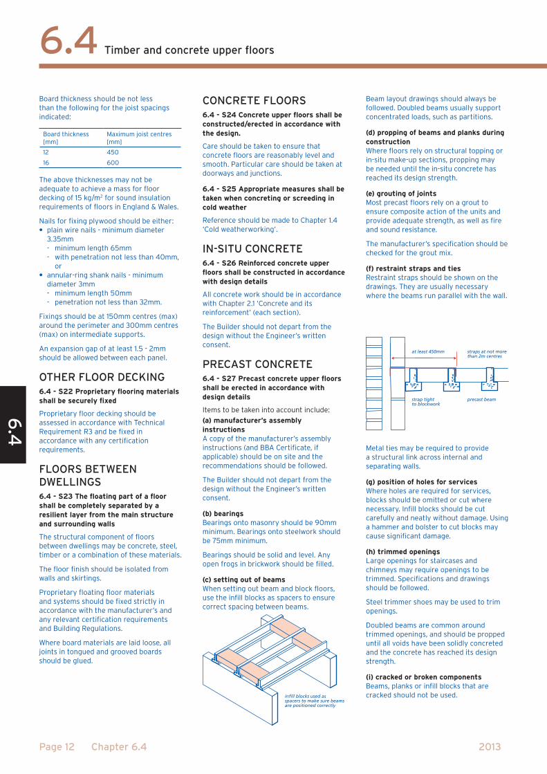
(c) setting out of beamsWhen setting out beam and block floors, use the infill blocks as spacers to ensure correct spacing between beams.
infill blocks used asspacers to make sure beamsare positioned correctly
Beam layout drawings should always be followed. Doubled beams usually support concentrated loads, such as partitions.
(d) propping of beams and planks during constructionWhere floors rely on structural topping or in-situ make-up sections, propping may be needed until the in-situ concrete has reached its design strength.
(e) grouting of jointsMost precast floors rely on a grout to ensure composite action of the units and provide adequate strength, as well as fire and sound resistance.
The manufacturer’s specification should be checked for the grout mix.
(f) restraint straps and tiesRestraint straps should be shown on the drawings. They are usually necessary where the beams run parallel with the wall.
at least 450mm
strap tightto blockwork
straps at not morethan 2m centres
precast beam
Metal ties may be required to provide a structural link across internal and separating walls.
(g) position of holes for servicesWhere holes are required for services, blocks should be omitted or cut where necessary. Infill blocks should be cut carefully and neatly without damage. Using a hammer and bolster to cut blocks may cause significant damage.
(h) trimmed openingsLarge openings for staircases and chimneys may require openings to be trimmed. Specifications and drawings should be followed.
Steel trimmer shoes may be used to trim openings.
Doubled beams are common around trimmed openings, and should be propped until all voids have been solidly concreted and the concrete has reached its design strength.
(i) cracked or broken componentsBeams, planks or infill blocks that are cracked should not be used.

6.4 6
.4
Page 13Chapter 6.4
Timber and concrete upper floors
2013
(j) clips for suspended ceilingSome designs include metal ceiling clips inserted between the planks or blocks so that timber battens can be fixed below.
clips inserted as planks are being laid
planks marked with position of clips
FIRE-STOPPING6.4 - S28 Penetrations in floors between dwellings shall be fire-stopped.
The specified method of fire-stopping should be carried out. There should be no holes or gaps for smoke to penetrate once the fire-stopping has been installed. Where downlighters are incorporated in a ceiling they should be installed inaccordance with the manufacturer’s instructions
APPENDIx 6.4-A
Span tables for solid timber floor joistsTables 1 and 2 in this Appendix are derived from the TRADA Technology Ltd. publication “Eurocode 5 span tables for solid timber members in floors, ceilings and roofs for dwellings (3rd edition)”.
The section sizes of the floor joists given in Tables 1 and 2 should be regularised, or be ALS or CLS to enable floors and ceilings to be level.
For upper floors with a 22mm thick chipboard decking and 12.5mm plasterboard ceiling, a dead load of between 0.25kN/m2 and 0.5kN/m2 may be assumed. Use the centre three columns from the tables.
For timber floors between dwellings, the dead load of the construction to meet acoustic performance is likely to be within the range 0.6kN/m2 to 0.7kN/m2, therefore use the three right-hand columns.
Floors based on these tables require strutting in accordance with Sitework clause 6.4 - S8.
Lightweight non-loadbearing partitions which weigh no more than 1.0kN (101.9kg) per metre run and are parallel to the joists may be supported by one or two additional joists placed immediately beneath them. The partitions should be fixed through the floor decking into the joist(s) beneath. In tables 1 and 2, one additional joist is generally sufficient. Where two additional joists are needed, the spans are markedwith an asterisk (eg 1.76*). For similar lightweight partitions which run at right-angles to the joists, the maximum spans in Tables 1 and 2 should be reduced by 10%. For all other additional loads, joist sizes should be designed by an Engineer in accordance with Technical Requirement R3.

6.4
6.4
Page 14 Chapter 6.4
Timber and concrete upper floors
2013
Table 1 - Permissible clear spans for domestic floor joists - strength class C16
Imposed load not exceeding 1.5 kN/m2 Service Class 1 or 2
Dead Load gk [kN/m2] excluding self-weight of joist
gk not more than 0.25 gk not more than 0.50 gk not more than 1.25
Size of joist Spacing of joists [mm]
400 450 600 400 450 600 400 450 600
Breadth [mm] Depth [mm] Maximum clear span [m]
38 97 1.76* 1.66* 1.43 1.64* 1.55* 1.35 1.43 1.35 0.71
38 120 2.36* 2.23* 1.94 2.18* 2.07* 1.80 1.86 1.77 1.5538 145 2.85* 2.74* 2.48 2.68* 2.58* 2.32 2.33 2.22 1.9638 170 3.33* 3.20* 2.90 3.14* 3.02* 2.73 2.74 2.63 2.3738 195 3.81* 3.67* 3.32 3.59* 3.45* 3.12 3.14 3.01 2.7138 220 4.29* 4.13* 3.74 4.05* 3.89* 3.52 3.53 3.39 3.06
44 97 1.89* 1.78* 1.54 1.76* 1.67* 1.45 1.53 1.45 1.2744 120 2.48* 2.39* 2.08 2.33* 2.21* 1.94 1.98 1.88 1.6644 145 2.99* 2.88* 2.61 2.82* 2.71* 2.45 2.46 2.36 2.0944 170 3.50* 3.37* 3.05 3.30* 3.17* 2.87 2.88 2.77 2.5044 195 4.00* 3.85* 3.49 3.78* 3.63* 3.29 3.30 3.17 2.8644 220 4.51* 4.33* 3.94 4.25* 4.09* 3.71 3.72 3.57 3.23
47 97 1.95* 1.84* 1.60 1.81* 1.72* 1.50 1.57 1.49 1.3147 120 2.54* 2.44* 2.15 2.39* 2.27* 2.00 2.04 1.94 1.7147 145 3.06* 2.94* 2.67 2.88* 2.77* 2.51 2.52 2.42 2.1547 170 3.58* 3.44* 3.12 3.37* 3.24* 2.94 2.95 2.83 2.5647 195 4.09* 3.94* 3.57 3.86* 3.71* 3.36 3.38 3.24 2.9347 220 4.60* 4.43* 4.02 4.34* 4.18* 3.79 3.80 3.65 3.30
50 97 2.00* 1.89* 1.65 1.87* 1.77* 1.54 1.61 1.53 1.3450 120 2.59* 2.49* 2.22 2.44* 2.34* 2.05 2.09 1.99 1.7550 145 3.12* 3.00* 2.72 2.94* 2.83* 2.56 2.57 2.47 2.2150 170 3.65* 3.51* 3.19 3.44* 3.31* 3.00 3.01 2.89 2.6150 195 4.17* 4.02* 3.65 3.94* 3.79* 3.44 3.45 3.31 3.0050 220 4.70* 4.52* 4.11 4.43* 4.26* 3.87 3.88 3.73 3.38
63 97 2.23* 2.11* 1.84 2.07* 1.97* 1.72 1.78 1.70 1.5063 120 2.80* 2.69* 2.44 2.64* 2.54* 2.28 2.30 2.19 1.9463 145 3.37* 3.24* 2.95 3.18* 3.06* 2.78 2.79 2.68 2.4263 170 3.94* 3.79* 3.45 3.72* 3.58* 3.25 3.26 3.13 2.8463 195 4.50* 4.33* 3.94 4.25* 4.09* 3.72 3.73 3.58 3.2563 220 5.06* 4.87* 4.44 4.78* 4.60* 4.18 4.20 4.04 3.66
75 120 2.96* 2.85* 2.59 2.79* 2.69* 2.44 2.45 2.35 2.0975 145 3.56* 3.43* 3.12 3.37* 3.24* 2.94 2.95 2.84 2.5775 170 4.16* 4.01* 3.65 3.93* 3.79* 3.44 3.45 3.32 3.0175 195 4.75* 4.58* 4.17 4.49* 4.33* 3.94 3.95 3.80 3.45
75 220 5.34* 5.15* 4.70 5.05* 4.87* 4.43 4.45 4.28 3.88
ALS/CLS
38 140 2.75* 2.64* 2.39 2.59* 2.49* 2.21 2.24 2.13 1.8838 184 3.60* 3.46* 3.14 3.39* 3.26* 2.95 2.96 2.84 2.5638 235 4.58* 4.40* 3.99 4.32* 4.15* 3.76 3.77 3.62 3.27
89 184 4.74* 4.57* 4.17 4.48* 4.32* 3.94 3.95 3.80 3.45
89 235 5.99* 5.78* 5.29 5.68* 5.48* 5.00 5.01 4.83 4.39
* Two additional joists required Normal bearing of 40mm to be doubled

6.4 6
.4
Page 15Chapter 6.4
Timber and concrete upper floors
2013
Table 2 - Permissible clear spans for domestic floor joists - strength class C24
Imposed load not exceeding qk = 1.5 kN/m2 or Qk = 0.90 kN Service Class 1 or 2
Dead Load gk [kN/m2] excluding self-weight of joist
gk not more than 0.25 gk not more than 0.50 gk not more than 1.25
Size of joist Spacing of joists [mm]
400 450 600 400 450 600 400 450 600
Breadth [mm] Depth [mm] Maximum clear span [m]
38 97 2.05* 1.94* 1.68 1.91* 1.80* 1.57 1.64 1.56 1.37
38 120 2.63* 2.53* 2.26 2.48* 2.38* 2.09 2.13 2.02 1.7838 145 3.17* 3.05* 2.77 2.99* 2.87* 2.60 2.61 2.51 2.2538 170 3.71* 3.57* 3.24 3.50* 3.36* 3.05 3.06 2.94 2.6538 195 4.25* 4.08* 3.71 4.00* 3.85* 3.49 3.50 3.36 3.0438 220 4.78* 4.60* 4.17 4.51* 4.33* 3.93 3.95 3.79 3.42
44 97 2.19* 2.07* 1.81 2.04* 1.93* 1.69 1.75 1.66 1.4644 120 2.77* 2.66* 2.41 2.61* 2.50* 2.24 2.26 2.15 1.9044 145 3.33* 3.20* 2.91 3.14* 3.02* 2.74 2.75 2.64 2.3844 170 3.90* 3.75* 3.40 3.67* 3.53* 3.20 3.22 3.09 2.7944 195 4.46* 4.29* 3.90 4.21* 4.04* 3.67 3.68 3.54 3.2044 220 5.01* 4.82* 4.39 4.73* 4.55* 4.13 4.15 3.98 3.61
47 97 2.26* 2.14* 1.87 2.10* 1.99* 1.74 1.80 1.71 1.5147 120 2.83* 2.72* 2.47 2.67* 2.56* 2.31 2.32 2.21 1.9647 145 3.40* 3.27* 2.97 3.21* 3.09* 2.80 2.81 2.70 2.4447 170 3.98* 3.83* 3.48 3.76* 3.61* 3.28 3.29 3.16 2.8647 195 4.55* 4.38* 3.98 4.30* 4.13* 3.75 3.77 3.62 3.2747 220 5.12* 4.93* 4.48 4.83* 4.65* 4.23 4.24 4.08 3.69
50 97 2.32* 2.20* 1.92 2.15* 2.04* 1.79 1.85 1.76 1.5550 120 2.88* 2.77* 2.52 2.72* 2.62* 2.37 2.38 2.27 2.0150 145 3.48* 3.34* 3.04 3.28* 3.15* 2.86 2.87 2.76 2.5050 170 4.06* 3.91* 3.55 3.83* 3.69* 3.35 3.36 3.23 2.9250 195 4.64* 4.47* 4.07 4.38* 4.22* 3.38 3.85 3.69 3.3550 220 5.22* 5.03* 4.58 4.93* 4.75* 4.32 4.33 4.16 3.77
63 97 2.52* 2.43* 2.14 2.38* 2.26* 1.99 2.03 1.94 1.7263 120 3.11* 2.99* 2.72 2.94* 2.83* 2.57 2.57 2.47 2.2263 145 3.74* 3.60* 3.28 3.54* 3.40* 3.09 3.10 2.98 2.7063 170 4.37* 4.21* 3.84 4.13* 3.98* 3.62 3.63 3.49 3.1763 195 5.00* 4.81* 4.39 4.72* 4.55* 4.14 4.15 4.00 3.6263 220 5.61* 5.41* 4.94 5.31* 5.12* 4.66 4.68 4.50 4.08
75 120 3.29* 3.17* 2.88 3.11* 2.99* 2.72 2.73 2.62 2.3875 145 3.96* 3.81* 3.48 3.74* 3.60* 3.28 3.29 3.16 2.8775 170 4.62* 4.45* 4.06 4.37* 4.21* 3.83 3.85 3.70 3.3675 195 5.27* 5.08* 4.64 4.99* 4.81* 4.38 4.40 4.23 3.85
75 220 5.92* 5.71* 5.22 5.61* 5.41* 4.93 4.95 4.76 4.33
ALS/CLS
38 140 3.07* 2.95* 2.67 2.89* 2.77* 2.51 2.52 2.42 2.1538 184 4.01* 3.86* 3.50 3.78* 3.63* 3.29 3.31 3.17 2.8738 235 5.10* 4.90* 4.46 4.81* 4.62* 4.20 4.21 4.04 3.65
89 184 5.25* 5.07* 4.63 4.98* 4.80* 4.38 4.39 4.23 3.85
89 235 6.64* 6.41* 5.87 6.30* 6.08* 5.56 5.57 5.37 4.89
* Two additional joists required Normal bearing of 40mm to be doubled

6.4
6.4
Page 16 Chapter 6.4
Timber and concrete upper floors
2013
INDEx
B
Bearings 3, 6, 8, 12
Boarding 10, 11
C
Chimneys 3
Chipboard 11
Clearance 6
Concrete 4, 5, 12
D
Dead loads 1
Decking 4, 5, 10, 11
Drilling 9
E
End bearings 3
F
Fire spread 3
Fire-stopping 13
Fixings 4
Floating floors 12
Flooring 3
I
Imposed loads 4
In-situ concrete 12
I-joists 7, 8, 9, 10
J
Joist hangers 2, 5, 6, 8
Joist sizes 1
Joist spacing 1, 4, 6
L
Levelling 6
Lightweight partitions 1
M
Masonry partitions 2
Metal web joists 7, 8, 9, 10
Moisture 4, 5
Multiple joists 7
N
Notching 9
O
Oriented strand board 11
Overlapping joists 10
P
Plywood 11
Pre-cast concrete 12
Proprietary systems 5, 12
R
Reinforcement 5, 12
Restraint strapping 3, 5, 9, 12
S
Separating walls 3
Shrinkage 2
Sound transmission 4, 5
Span 1, 8
Strength class 1
Structural steel 3, 5, 7
Strutting 2, 5, 8
Supporting structure 1
T
Timber floors 4, 5
Timber joists 9, 10
Trimming joists 2, 6