part 6 assembly language & instruction...
TRANSCRIPT

Part 6
Assembly Language &
Instruction Set
(Hall: Ch3; Brey: Ch8-1; Triebel: Ch3)
(Brey: Ch4-6; D. Hall: Ch6)
ELEG 3230B
Microprocessors and Computer
Systems
ELEG 3230B - Part 6
Programming in 8088/8086
Three levels of languages available to program a microprocessor:
Machine Languages, Assembly Languages, and High-level Languages.
Machine Language
A sequence of binary codes for the instruction to be executed by microcomputers.
Long binary bits can be simplified by using Hexadecimal format.
It is difficult to program and error prone.
Different uP (micro-processor) uses different machine codes.
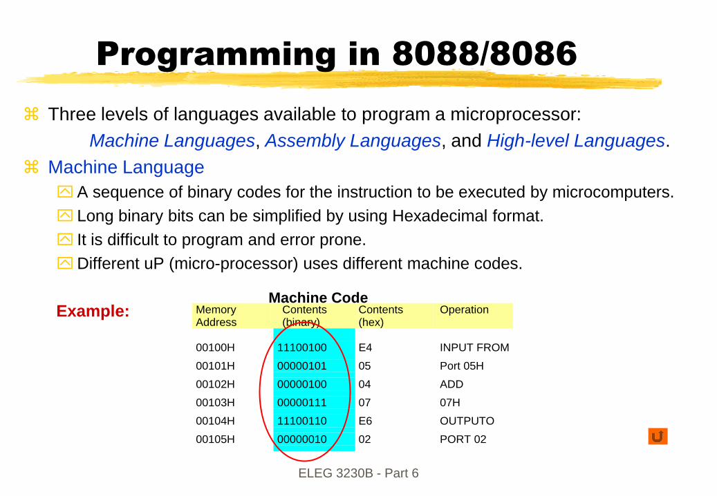
Example: Memory Address
Contents (binary)
Contents (hex)
Operation
00100H 11100100 E4 INPUT FROM
00101H 00000101 05 Port 05H 00102H 00000100 04 ADD
00103H 00000111 07 07H
00104H 11100110 E6 OUTPUTO
00105H 00000010 02 PORT 02
Machine Code

ELEG 3230B - Part 6
Programming in 8088/8086 (cont.)
Assembly Language
To simplify the programming, assembly language (instead of machine language) is
used.
Assembly language uses 2- to 4-letter mnemonics to represent each instruction
type. E.g. “Subtraction” is represented by SUB
Four fields in assembly language statement:
Label, OP Code, Operand and Comment fields.
Programs will be „translated‟ into machine language, by Assembler, so it can be
loaded into memory for execution.
High-Level Language
High level languages, like C, Basic or Pascal, can also be used to program
microcomputers.
An interpreter or a compiler is used to „translate‟ high level language statement to
machine code.
High level language is easier to read by human and is more suitable when the
programs involves complex data structures.

ELEG 3230B - Part 6
Assemblers
Programming the instructions directly in machine code is possible but very
time consuming as each basic instruction can have one of several different
machine codes depending on how the data is stored.
The process of converting the microprocessor instructions to the binary
machine code can be performed automatically by a computer program,
called an ASSEMBLER. Popular assemblers include IBM macro Assembler,
Microsoft Macro Assembler (MASM) and Borland Turbo Assembler
(installed on IE NT Network).
Most assemblers accept an input text file containing lines with a rigorously
defined syntax split into four fields.
Not all fields need to be present in a line. Eg. A line can be just a comment
line if it starts with semicolon;
Label Mnemonic/directive Operands commentFRED: ADD AL,0FH ;Adds 0FH to register AL

ELEG 3230B - Part 6
Program Trapping (Tracing)
Most microprocessors have a mode of operation which allows a program
to be stopped after each instruction and the execution of another program
(debugging program) to allow program debugging (examining the
operation of a program to find errors [bugs]).
Debugging mode is entered by setting the T (trap) flag in the FLAGS
register of the Intel 80X86 (or the trace flag in the status register of the
Motorola 68000). ( check ex. 12-1 of Brey‟s)
Typical debugging methods
Single stepping and examine the register and memory contents after each
instruction (time consuming)
Program tracing (i.e. finding the sequence of instructions being executed by
the program)
Breakpoints (stopping a program at a point decided by the programmer to
allow examination of the registers)
Memory dump (outputting the contents of memory)

ELEG 3230B - Part 6
Fields in Assembler
<label> <Mnemonic or directive> <operands> <;comment>
Comment field contains internal program documentation to improve human readability - use meaningful comments
Operand field contains data or address used by the instruction.
The following conventions typically apply:
MOV AX, [10H+01] ; load word into AX
Destination
AddressMnemonic source address (offset 11H)
bracket [ ] denotes address

ELEG 3230B - Part 6
Fields in Assembler (cont.)
<label> <Mnemonic or directive> <operands> <;comment>
Mnemonic/directive field contains the abbreviation for the processor
instruction (eg. MOV) or an assembler DIRECTIVE. A directive produces no
object code but is used to control how the assembler operates.
Examples of directives include
END - indicate the end of a program listing,
FRED LABEL NEAR - define “FRED” as a near label
TOM EQU 1000H - define “TOM” as the number 1000H
Label field contains a label which is assigned a value equal to the address
where the label appears.

ELEG 3230B - Part 6
Assembly Language Programs
Writing assembler program takes longer time than programming in a high level language like C.
Example:
Two long integers may be added in C language by
X=Y+Z;A similar addition in Assembly needs 6 lines :
; Assume the three numbers are referenced at
; three memory locations [X],[Y],[Z]
MOV AX, [Y] ; load from address [Y] into register AX
MOV DX [Y+2] ; load high-order word to DX
ADD AX, [Z] ; add low-order word;
ADC DX, [Z+2] ; add with carry high-order word;
MOV [X], AX ; store result at memory address X
MOV [X+2], DX
Note: [x] and [y] are not of proper format in assembly; x and y should be replaced with two numbers representing the offset address in a real program.

ELEG 3230B - Part 6
So Why Program in Assembler?
Assembler language instruction has a one-to-one correspondence with
the binary machine code: the programmer controls precisely all the
operations performed by the processor (a high level language relies on a
compiler or interpreter to generate the instructions).
Assembler can generate faster and more compact programs
Assembler language allows direct access and full control of input/output
operations
However, high-level language programs are easier to write and develop
than assembler language programs

ELEG 3230B - Part 6
Advantages of High-level languages
Block structure code: programs are most readable when they are broken into “logical blocks” that perform specific function.
Productivity: easier to program
Level of complexity: no need to know the hardware details
Simple mathematics formula statement available
Portability: only need to change the compiler when it is ported to other machine
Abstract data types: different data types like floating-point value, record and array, and high precision value.
Readability
Actually you can incorporate Assembly programs in C/C++ ( check out Brey Ch.7)

ELEG 3230B - Part 6
Intel 8088/8086 Instruction Set
Overview
Intel 8088 has ninety basic (ie not counting addressing mode
variants) instructions
Instructions belong to one of the following groups: data
transfer, arithmetic, logic, string manipulation, control
transfer and processor control.

ELEG 3230B - Part 6
Instruction Set
The total number of instruction in an instruction set is limited by the
number of possible bits available for encoding the op-code.
Usually not all the bits in a word are used for the op-code since some bits
are needed for the addressing information. This limit may be worked
around by using 2,3 or more words for instructions (slower since more
read cycles from memory are needed)
Short word length machines suffer from limited instruction set and
memory address space. Hence long word length machines are more
powerful.

ELEG 3230B - Part 6
Instruction Set (cont.)
Microprocessors can perform a range of basic operations defined by their
instruction set
The instruction set is a set of binary codes known as op-codes which can
be decoded by the microprocessor‟s control unit
Op-codes are often combined with some address information to specify
the location of the operands (the data for the instruction)
7 0 7 0 7 0 op-code data/address data/address
Example machine code instruction Instruction machine code
IN AL,05h E4
05
Increase in memory address

ELEG 3230B - Part 6
Intel 8088 Machine Code
Instruction Format
Machine code for an instruction consists of a binary code of variable length
(typically 2 bytes, but can be 1 byte to 4 bytes depending on the
instruction). Machine code includes all the necessary information (opcode,
address, data) for an instruction
The machine codes for the Intel 8088 is listed in the Intel Microprocessor
data book.
Example : Move and Jump instructions (pp47 Hall‟s)(Brey‟s ch4-1)

ELEG 3230B - Part 6
Intel 8088 Machine Code
Instruction Format (cont.)
Ex: B4 06 =? MOV AH, 61011 0100 00000110

Instructions Set
Also from
http://www.emu8086.com/assembly_language_tutorial_assembler_reference/8086_instruction_set.html

ELEG 3230B - Part 6
Data Transfer (14)
MOV, PUSH, POP, XCHG, IN, OUT, XLAT, LEA, LDS, LES, LAHF, SAHF, PUSHF, POPF
Arithmetic (20)
ADD, ADC, INC, AAA, BAA, SUB, SSB, DEC, NEG, CMP, AAS, DAS, MUL, IMUL, AAM,
DIV, IDIV, AAD, CBW, CWD
Logic (12)
NOT, SHL/SAL, SHR, SAR, ROL, ROR, RCL, RCR, AND, TEST, OR, XOR
String Manipulation (6)
REP, MOVS, XMPS, SCAS, LODS, STOS
Control Transfer (26)
CALL, JMP, RET, JE/JZ, JL/JNGE, JLE/JNG, JB/JNAE, JBE/JNA, JP/JPE, JO, JS,
JNE/JNZ, JNL/JGE, JNLE/JG, JNB/JAE, JNBE/JA, JNP/JPO, JNO, JNS, LOOP,
LOOPZ/LOOPE, LOOPNZ/LOOPNE, JCXZ, INT, INTO, IRETR
Processor Control (12)
CLC, CMC, STC, CLD, STD, CLI, STI, HLT, WAIT, ESC, LOCK, NOP
Intel 8088/8086 Instruction Set
Overview

ELEG 3230B - Part 6
I. Data Movement Instructions (14)
(abbreviations below: d=destination, s=source)
General Data Movement Instructions
MOV d,s - moves a byte or word; most commonly used instruction
PUSH s - stores a word (register or memory) onto the stack
POP d - removes a word from the stack
XCHG d,s - exchanges data, reg.-reg. Or memory to register
XLAT - translates a byte using a lookup table (has no operands)
IN d,s - moves data (byte or word) from I/O port to AX or AL
OUT d,s - moves data (byte or word) from AX or AL to I/O port
LEA d,s - loads effective address (not data at address) into register
LDS d,s - loads 4 bytes (starting at s) to pointer (d) and DS
LES d,s - loads 4 bytes (starting at s) to pointer (d) and ES
(continue in next page))

ELEG 3230B - Part 6
Data Movement Instructions (cont.)
LAHF - loads the low-order bytes of the FLAGS register to AH
SAHF - stores AH into the low-order byte of FLAGS
PUSHF - copies the FLAGS register to the stack
POPF - copies a word from the stack to the FLAGS register
Instructions for moving strings
String instructions are repeated when prefixed by the REP mnemonic (CX
contains the repetition count)
MOVS d,s - (MOVSB, MOVSW) memory to memory data transfer
LODS s - (LODSB and LODSW) copies data into AX or AH
STOS d - (STOSB, STOSW) stores data from AH or AX

ELEG 3230B - Part 6
Data movement using MOV
MOV d,s
d=destination (register or effective memory address),
s=source (immediate data, register or memory address)
MOV can transfer data from:
any register to any register (except CS register)
memory to any register (except CS)
immediate operand to any register (except CS)
any register to a memory location
immediate operand to memory
MOV cannot perform memory to memory transfers (must use a register as an intermediate storage).
MOV moves a word or byte depending on the operand bit-lengths; the source and destination operands must have the same bit length.
MOV cannot be used to transfer data directly into the CS register.
Typical number of clock cycles to carry out MOV are
2 clocks for register-register
4 clocks for immediate-register
8+ea clocks for memory-register (8086)
12+ea clocks for memory-register (8088)
clock cycle: will be discussed
in part 08.
ea: a value depends on
effective address

ELEG 3230B - Part 6
Number of clock cycles to
calculate effective address
The number of clock cycles needed for an instruction depends on the
addressing mode.
For 8088/8086 systems, calculation of the effective address (16 bits) of
the operand can take several clock cycles (these extra clock cycles are
not needed for 80286 or later microprocessors):
Examples Extra clock cycles needed for calculating effective address:
Overriding the default segment register adds 2 clock cycles (ea+2)
Instructions which involve purely register to register or immediate data to
register operations do not need extra clock cycles to calculate the
effective address.
Addressing mode Example Clock
register indirect MOV CL,[DI] 5
Direct MOV CL,FRED 3 Based index MOV BL,[BP+DI] 7
Based index (displacement) MOV CX,[BP+DI+FRED] 11
segment override prefix MOV AL,ES:[SI] ea+2

ELEG 3230B - Part 6
The stack
The stack is a block of memory reserved for temporary storage of dataand registers. Access is LAST-IN, FIRST-OUT (LIFO)
The last memory location used in the stack is given by (the effectiveaddress calculated from the SP register) and (the SS register):
Example:
Memory Map of a stack
SS=1000h
SP=2000h 11FFEh empty
11FFFh empty
SP 12000h data Top of Stack
12001h data
12002h data
data
data
data
data
Max. 1FFFFh data Bottom of Stack
memory
increasing

ELEG 3230B - Part 6
The stack
Data may be stored onto the stack using the PUSH instruction - this
automatically decrements SP by 2 (all stack operations involve words).
The POP instruction removes data from the stack (and increments SP by
2).
The stack may be up to 64K-bytes in length.

ELEG 3230B - Part 6
PUSH and POP instructions
Examples:
PUSH AX ; stores AX onto the stack
POP AX ; removes a word from the stack and loads it into AX
PUSHF ; stores the FLAGS register onto the stack
POPF ; removes a word from the stack and loads it into FLAGS
PUSH may be used with any register to save a word (the register contents)
onto the stack. The usual order (e.g. as with MOV) of storing the lower order
byte in the lower memory location is used.
PUSH may also be used with immediate data, or data in memory.
POP is the inverse of the PUSH instruction; it removes a word from the top
of the stack. Any memory location or 16-bit register (except CS) may be
used as the destination of a POP instruction.
PUSHF and POPF saves and loads the FLAGS register to/from the stack,
respectively.

ELEG 3230B - Part 6
Exchange Instruction (XCHG)
XCHG exchanges the contents of two registers or a register and memory.
Both byte and word sized exchanges are possible.
Examples:
XCHG AX,BX; exchange the contents of AX and BX
XCHG CL,BL; exchange CL and BL contents
XCHG DX,FRED; exchanges content of DX and memory DS:FRED
Memory to Memory exchanges using XCHG are NOT allowed.
ELEG 3230B - Part 6
Translate Instruction (XLAT)
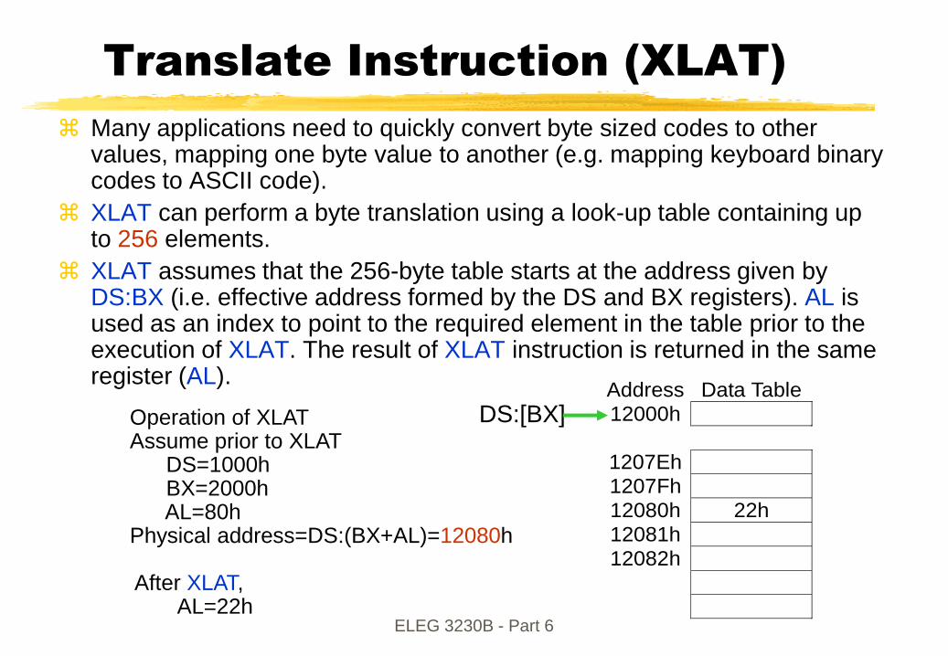
Many applications need to quickly convert byte sized codes to other values, mapping one byte value to another (e.g. mapping keyboard binary codes to ASCII code).
XLAT can perform a byte translation using a look-up table containing up to 256 elements.
XLAT assumes that the 256-byte table starts at the address given by DS:BX (i.e. effective address formed by the DS and BX registers). AL is used as an index to point to the required element in the table prior to the execution of XLAT. The result of XLAT instruction is returned in the same register (AL).
Address Data Table
12000h
1207Eh
1207Fh
12080h 22h
12081h
12082h
Operation of XLATAssume prior to XLAT
DS=1000hBX=2000hAL=80h
Physical address=DS:(BX+AL)=12080h
After XLAT,AL=22h
DS:[BX]

ELEG 3230B - Part 6
LEA & LDS
LEA (load effective address)
LEA loads the offset of a memory address into a 16-bit register. The offset address may be specified by any of the addressing modes.
Examples (with BP=1000h):
LEA AX,[BP+40h]; SS:[1000h+40h] = SS:[1040h]; load 1040h into AX
LEA BX,FRED; load the offset of FRED (in data segment) to BX
LEA CX,ES:FRED; loads the offset of FRED (in extra segment) to CX
LDS - Load data and DS
LDS reads two words from the consecutive memory locations and loads them into the specified register and the DS segment registers.
Examples (DS=1000h initially)
LDS BX,[2222h]; copies content of 12222h to BL, 12223h to BH, and 12224h and 12225h to DS register
LDS is useful for initializing the SI and DS registers before a string operation. E.g. LDS SI, sting_pointer
The source for LDS can be displacement, index or pointer register (except SP).

ELEG 3230B - Part 6
LES - Load data and ES
LES reads two words from memory and is very similar to LDS except that
the second word is stored in ES instead of DS.
LES is useful for initializing that DI and ES registers for strings operation.
Example (with DS=1000h):
LES DI, [2222h]; loads DI with contents stored at 12222h and 12223h and
loads ES with contents at 1222h and 12225h

ELEG 3230B - Part 6
LAHF, SAHF
LAHF and SAHF instructions
LAHF (load AH with the low-order byte of the FLAGS register) and SAHF
(Store AH into the low-order byte of the FLAG register)
very rarely used instructions - originally present to allow translation of
8085 programs to 8086.

ELEG 3230B - Part 6
IN, OUT
IN and OUT instructions
Examples:
IN AX, 0C8h ; reads port address at 0C8h (8-bit address) and loads into AX
IN AL, DX ; reads the port address given by DX and loads into AL
OUT p8 , AX ; sends the data in AX to port p8
OUT DX, AX ; sends the data in AX to port given by DX
IN reads data from the specified IO port (8-bit or 16-bit wide) to the
accumulator (AL or AX).
The IO port can be an immediate address (8-bit only) or specified by a variable
or the register DX. (Only DX can be used.)
OUT sends data from the accumulator register to the specified I/O port. Both
byte and word sized data may be sent using IN and OUT.
Only registers AL and AX are allowed in IN and OUT instruction.

ELEG 3230B - Part 6
II. Arithmetic Instructions(20)
Intel 8088 has 20 instructions for performing integer addition, subtraction,multiplication, division, and conversions from binary coded decimal to binary.
ADD d,s ; add byte or word
ADC d,s ; add byte or word with carry
Addition INC d ; increment byte or word by adding 1
DAA ; decimal adjust after addition
AAA ; ASCII adjust for addition
SUB d,s ; subtract, d-sd
SBB d,s ; subtract with borrow
Subtraction DEC d ; decrement byte or word (subtract 1)
DAS ; decimal adjust after subtraction
AAS ; ASCII adjust for subtraction

ELEG 3230B - Part 6
Arithmetic Instructions (cont.)
MUL s ; multiply byte or word, unsigned
Multiply IMUL s ; integer multiply, signed
AAM ; ASCII adjust for multiply
DIV s ; unsigned byte or word divide
Division IDIV s ; signed byte or word divide
AAD ; ASCII adjust for divide
NEG d ; Negate, i.e. multiply by -1
Other CBW ; convert byte to word and sign extend
CWD ; convert word to double word
CMP d, s ; compare byte or word

ELEG 3230B - Part 6
Numbers in microprocessors
revisited
See e.g. (D.V. Hall) ch.1 & ch.11;
Signed integers may be represented simply by the use of 2‟s complementbinary system, (hexadecimal is for human readability):
Examples (For 16-bit words)
Decimal fractions may be represented by binary coded decimal (BCD).
Even larger integers and real numbers may be represented by floatingpoint numbers e.g. In decimal
8.54x10³ exponent
significand (mantissa) base
Floating point number formats are specified by the microprocessor manufacturer.
Decimal Binary Hex 1 0000 0000 0000 0001 0001
-1 1111 1111 1111 1111 FFFF
29 0000 0000 0001 1101 001D
-29 1111 1111 1110 0011 FFE3
32,767 0111 1111 1111 1111 7FFF
-32,768 1000 0000 0000 0000 8000
4 bits = 1 nibble
8 bits = 1 byte
16 bits = 1 word (16 bit machines)
32 bits = 1 double-word
64 bits = 1 Quad-word

ELEG 3230B - Part 6
Number formats in the Intel
80X87 co-processors
D. Hall fig11-16
0
0
0
WORD INTEGER S MAGNITUDE (TWO‟S COMPLEMENT)
15
SHORT INTEGER MAGNITUDES (TWO‟S COMPLEMENT)
031
LONG INTEGER S MAGNITUDE (TWO‟S COMPLEMENT)
63
PACKED DECIMAL
7279 0
MAGNITUDEd17 d1
6
d15 d1
4
d13 d12 d11 d10 d9 d8 d7 d6 d5 d4 d0d3 d2 d1S X
SHORT REAL SBIASED
EXPONENTSIGNIFICAND
02331
LONG REAL SBIASED
EXPONENT SIGNIFICAND
05263
TEMPORARY REAL
79
S SIGNIFICANDBIASED
EXPONENT 1
64 63
INCREASING SIGNIFICANCE
NOTES:
S = Sign bit (0 = positive 1 = negative)
dn = Decimal digit (two per byte)
X = Bits have no significance; 8087 ignores when loading, zeros when storing
= Position of implicit binary point
I = Integer bit of significance; stored in temporary real, implicit in short and long real
Exponent Bias (normalized value):
Short Real: 127 (7FH)
Long Real: 1023 (3FFH)
Temporary Real: 16383 (3FFFH)
Unpacked BCD: 1 digit per byte
Packed BCD: 2 digits per byte

ELEG 3230B - Part 6
Addition
Binary addition of two bytes or two words are performed using:
ADD d,s
ADD adds bytes or words in d and s and stores result in d.
The operands d and s can use the same addressing modes as in MOV.
Addition of double-word is achieved by using the carry bit in the FLAGSregister.
The instruction
ADC d,s
automatically includes the carry flag, and is used to add the moresignificant word in a double-word addition.

ELEG 3230B - Part 6
Addition (cont.)
Example: addition of two double words stored at [x] and [y]
MOV AX, [x] ; Loads AX with the word stored at location [x]
MOV DX, [x+2] ; Loads the high order word
ADD AX, [y] ; Adds the low order word at [y]
ADC DX, [y+2] ; Add including the carry from the low order words
Note: [x] and [y] are not of proper format in assembly; x and y should be replaced withtwo numbers representing the offset address in a real program.
Addition of binary coded decimal numbers (BCD) can be performed by using ADD or ADC followed by the DAA instruction to convert the number in register AL to a BCD representation. (see example)
Addition of numbers in their ASCII form is achieved by using AAA (ascii adjust after addition).

ELEG 3230B - Part 6
ASCII adjust for Addition (AAA)
ASCII codes for the numbers 0 to 9 are 30H to 39H respectively.
The ascii adjust instructions convert the sum stored in AL to two-byteunpack BCD number which are placed in AX.
When 30H is added to each byte, the result is the ASCII codes of thedigits representing the decimal for the original number in AL.
Example: Register AL contains 31H (the ASCII code for 1), BL contains 39H (theASCII code for 9).
ADD AL, BL ; produces the result 6AH which is kept in AL.
AAA ; converts 6AH in AL to 0100H in AX
Addition of 30H to each byte of AX can then produce the result 3130H (the ASCIIcode for 10 which is the result of 1+9)
ASCII code decimal
AL 31H 1
BL + 39H + 9
ADD AL, BL AL 6AH 10
after AAA, AX = 0100H
add 30H to each byte 3130H
Note : the result after AAA is still the
same if initial conditions are AL=01h,
BL=09h

ELEG 3230B - Part 6
Subtraction
Subtraction of two bytes or two words is performed using:
SUB d, s ; d stores the result of (d-s)
The number in the s operand is subtracted from the d operand and the result is stored in d. s and d are found using the same addressing modes as MOV.
If s is larger than d, the result is negative (in 2‟s complement form).
The subtraction of two double-word numbers is performed using SUB for subtraction of the low-order words, and SBB to subtract the high-order words. SBB adds the carry flag to s before performing the subtraction d-s. SBB will update the carry flag after execution.
Subtraction of binary-coded-decimal numbers is achieved using SUB (or SBB) followed by DAS (decimal adjust after subtraction) instruction which converts the number stored in the accumulator to binary coded decimal.
AAS gives the ASCII coded numbers after SUB (or SBB). AAS converts AL to two bytes in AX. The ascii code can then be obtained by simply adding 30H to each byte.

ELEG 3230B - Part 6
Multiplication
MUL s; multiplies two bytes or two words which are unsigned (i.e. not
two‟s complement). One of the multiplicands is the accumulator (AX or AL)
and the other is specified by a register or the contents of a memory
location (no immediate addressing).
The result of the multiplication of two bytes is stored in AX.
When two words are multiplied, the result has a length of 32 bits. The
high-order word is stored in DX.
IMUL s; multiplies two signed numbers (s and AX or AL).
AAM (ascii adjust after multiplication) converts the contents of AL into two
separate digits - one is in AL and the other is in AH. Addition of 30H will
then convert AL and AH to the ASCII code of the original result. AAM will
give a correct answer only if the two multiplicands are each less than ten
(i.e. it is necessary to first subtract 30H from the ascii codes before
multiplying).
ELEG 3230B - Part 6
Division
An unsigned word placed in the accumulator can be divided using
DIV s
where the divisor s is a byte sized number in a register or in memory. Immediate addressing is not allowed with DIV.
The division of a word by DIV produces an 8-bit quotient which is stored in AL, and a remainder which is placed in AH. (Q: Are 8 bits enough?)
An unsigned double-word may be divided by a word using
DIV s
The double word is in AX and DX (most significant word in DX) and s is the content of a 16-bit register or the content of a memory location. The 16-bitquotient is placed in AX and the 16-bit remainder is placed in DX
Division of a word by a word is done by filling DX with zero.
IDIV operates in the same way as DIV for signed operands.
AAD (ascii adjust for divide) is used to convert two unpacked binary coded numbers in AL and AH to binary. AAD is used before a division.

ELEG 3230B - Part 6
Sign Extend Instructions
CBW (convert byte to word) sign extends an 8-bit two‟s complement
number in AL to a 16-bit two‟s complement number in AX. Sign extend
involves either putting zeros in the most significant byte if the original byte
is positive, or filling the most significant byte with ones if the original byte
is negative.
CWD (convert word to double-word) sign extends AX to a double word.
The most significant word is DX.
Example:
MOV AX, 0 ; AH = 0, AL = 0
MOV AL, -5 ; AX = 00FBh (=251)
CBW ; AX = 0FFFBh (=-5)
RET
ELEG 3230B - Part 6
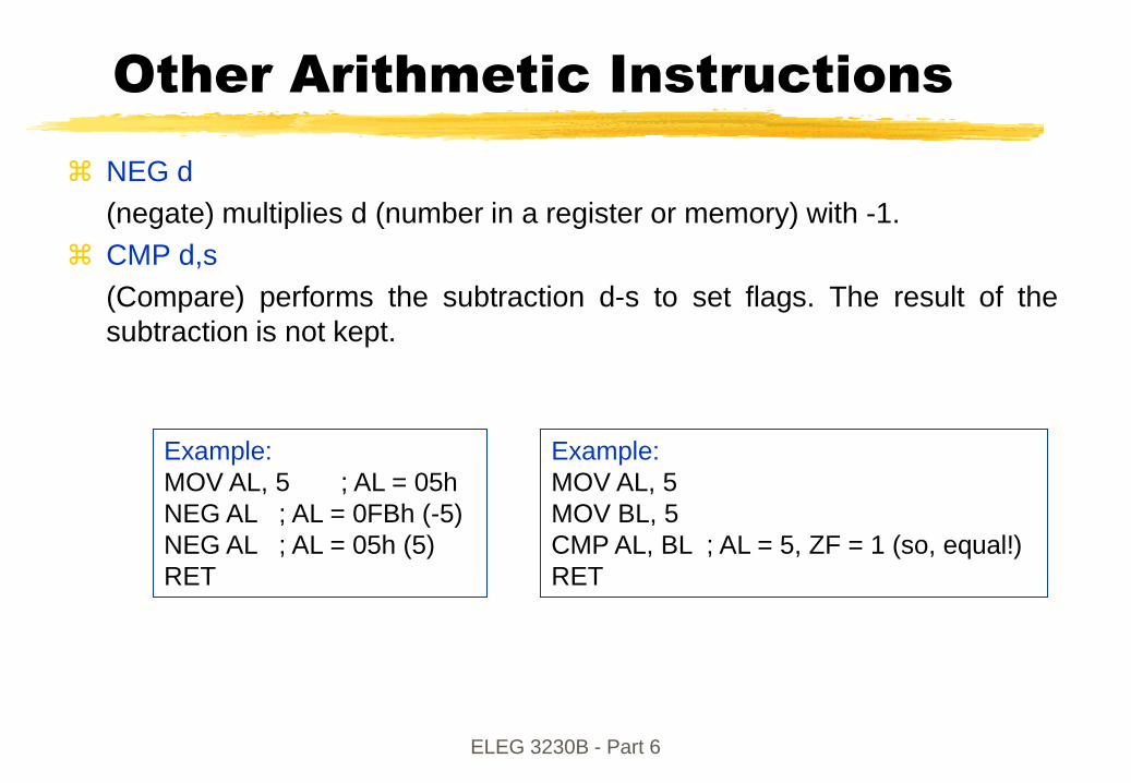
Other Arithmetic Instructions
NEG d
(negate) multiplies d (number in a register or memory) with -1.
CMP d,s
(Compare) performs the subtraction d-s to set flags. The result of the
subtraction is not kept.
Example:
MOV AL, 5 ; AL = 05h
NEG AL ; AL = 0FBh (-5)
NEG AL ; AL = 05h (5)
RET
Example:
MOV AL, 5
MOV BL, 5
CMP AL, BL ; AL = 5, ZF = 1 (so, equal!)
RET

ELEG 3230B - Part 6
III. Logic and bit manipulation
Instructions (12)
The binary bits in a byte or word can be manipulated directly using the
following set of 12 instructions:
AND d, s ; Logical AND, result put in d
NOT d ; Complements each bit of d
Logical OR d, s ; Logical OR, result stored in d
XOR d, s ; LOGICAL XOR, result put in d
TEST d, s ; AND to update flags P,Z, S. d unchanged
SAL/SHL d, c ; shift bits left c times. Insert zero
Shift SAR d, c ; shift right c times. Insert sign bit
SHR d, c ; shift right c times. Insert zeros

ELEG 3230B - Part 6
Logic and bit manipulation
Instruction (Cont.)
ROL d, c ; rotates all bits left c times
Rotate ROR d, c ; rotate all the bits right c times
RCL d, c ; rotate left through carry flag, c times
RCR d, c ; rotate right through carry flag, c times
For the 8088/8086, the count in the shift and rotate instructions is either
=1 or a number stored in the CL register. (immediate count is only allowed
in the 80286 and above)
The destination operand, d, can be registers or a memory location. The
source operands in the logic instructions can be immediate data, another
register or the contents of a memory location. Both bytes and word sized
operands are permitted.

ELEG 3230B - Part 6
Shift and Rotate
A shift left by one bit position is equivalent to multiplying by two. Using
SAL the most significant bit is shifted into the carry flag and the least
significant bit is filled with a zero.
A shift right by one position is equivalent to dividing by two when the sign
bit is maintained (using SAR).
ROL and ROR rotate the bits left and right respectively. The ROL
instruction fills the least significant bit with the most significant bit which is
also placed in the carry flag. ROR fills the most significant bit with the
least significant bit.

ELEG 3230B - Part 6
Shift and Rotate (cont.)
C
SHL
Target register or memory
0 0
C
SAL
Target register or memory
0 0
C
SHR
Target register or memory
00
C
SAR
Target register or memory
0Sign
bit
C
RCL
Target register or memory
0
Target register or memoryC
ROL 0
Brey Fig 5-9, 5-10
Shift Rotate
C
RCR
Target register or memory
0
C
ROR
Target register or memory
0
C
: carry flag
=(shift logical left)
(shift arithmetic left)

ELEG 3230B - Part 6
List file of 8086 assembly language program to produce
packed BCD from two ASCII characters
1 ; 8086 PROGRAM F4--05.ASM
2 ; ABSTRACT: Program produces a packed BCD byte from 2 ASCII -encoded digits
3 ; The first ASCII digit (5) is loaded in BL.
4 ; The second ASCII digit (9) is loaded in AL.
5 ; The result (packed BCD ) is left in AL
6 ; REGISTERS ; Uses CS, AL, BL, CL
7 ; PORTS ; None used
8
9 0000 CODE SEGMENT
10 ASSUME CS:CODE
11 0000 B3 35 START: MOV BL, „5‟ ; Load first ASCII digit into BL (35H)
12 0002 B0 39 MOV AL, „9‟ ; Load second ASCII digit into AL (39H)
13 0004 80 E3 0F AND BL, 0FH ; Mask upper 4 bits of first digit (05H)
14 0007 24 0F AND AL, 0FH ; Mask upper 4 bits of second digit (09H)
15 0009 B1 04 MOV CL, 04H ; Load CL for 4 rotates required
16 000B D2 C3 ROL BL, CL ; Rotate BL 4 bit positions (50H)
17 000D 0A C3 OR AL, BL ; Combine nibbles, result in AL (59H)
18 0000F CODE ENDS
19 END START

ELEG 3230B - Part 6
A string is a series of bytes or a series of words in sequential memory
locations. It often consists of ASCII character codes.
REP - An Instruction prefix; repeat the following instruction until CX=0
MOVS d,s - (MOVSB, MOVSW) memory to memory data transfer
COMPS - (COMPSB and COMPSW) compare two strings
SCAS - (SCASB and SCASW) scan a string, compare with a string byte in
AL or a string word in AX.
LODS s - (LODSB and LODSW) copies data into AX or AH
STOS d - (STOSB, STOSW) stores data from AH or AX
IV. Strings Instruction (6)

ELEG 3230B - Part 6
IV. Instruction for moving strings
String operations assume the string pointers (ie the registers which keep the
address of where the string is stored in memory):
DS:SI - source string address
ES:DI - destination string address
LES and LDS are useful for initializing these registers
CX stores the count for the number of times the string instruction must be
repeated to completely process the string.
The SI and DI index registers are incremented or decremented (depending
on the value of the direction flag in the FLAGS register) CX times when the
REP prefix is attached to the string instruction and the string instruction is
repeated CX times.
Direction flag in the FLAGS register may be set or cleared using the STD
and CLD instructions respectively. (D=1: D=0:)

ELEG 3230B - Part 6
Instruction for moving strings (cont.)
MOVS can transfer byte or word-sized data from memory to memory (the
only instruction capable of memory to memory transfer)
Example: REP MOVS data1, data2
It copies string located at data2 to data1. Labels defined with DB or DW
determines whether byte or word-sized transfer are used. Register DS:SI
and ES:DI must be initialized with data2 and data1, respectively.
MOVSB moves byte sized data and MOVSW moves word-sized data -
operation is identical to MOVS but no operands are needed.

ELEG 3230B - Part 6
REP prefix
REP repeats a string instruction and automatically decrements the count
in register CX after each repetition until CX equals zero.
Example (with CX=5)
REP MOVSB; repeats MOVSB 5 times i.e. transfers 5 bytes.
REPE (repeat while equal) and REPZ (repeat while zero) operate in the
same way but are used for SCAS and CMPS. REPE and REPZ have an
extra (in addition to CX being nonzero) condition of repeating only when
the zero flag is set; ie the string comparison is stopped as soon as the two
strings are not equal.
REPNZ and REPNE also repeat while CX is non zero. The extra condition
is that the zero flag is clear for the repetition to continue.
3 ways to repeat a string instruction are
REP - repeat if CX is nonzero
REPE, REPZ - repeat if CX is nonzero and the zero flag is 1
REPNZ, REPNE - repeat if CX is nonzero and the zero flag is 0

ELEG 3230B - Part 6
LODS and STOS string instructions
LODS loads the accumulator register with a byte or word from memory
location DS:SI and automatically increments the SI register if D=0 in the
FLAGS register (automatically decrements SI if D=1 in the FLAGS register.)
Example (assuming DATA1 is the label of DS:SI)
LODS DATA1 ;
Either
- loads AL with the contents of DATA1 if DATA1 is the label of the
address where a byte sized data is stored. SI=SI+/-1; or
- loads AX with a word if DATA1 refers to a word storage location.
SI=SI+/-2
LODSB and LODSW explicitly specifies whether to load a byte or a word
into the accumulator register.

ELEG 3230B - Part 6
LODS and STOS string instructions
(cont.)
STOS/STOSB/STOSW are the inverse of LODS/LODSB/LODSW and
stores a byte or word of data at memory location ES:DI
Examples
STOS DATA1 ; stores accumulator at ES:DI (byte or word - depend
; on DATA1)
STOSB ; stores a byte at ES:DI
STOSW ; stores a word at ES:DI
For LODS instruction, DS may be overridden as the source segment, but
for STOS instruction, ES must always be the destination segment.

ELEG 3230B - Part 6
CMPS and SCAS string instructions
CMPS (compare string) compares the bytes or words (depending on the
definition used for the label operands) stored at DS:SI and ES:DI. CMPS is
often used with the prefix REPZ, with CX set to the length of the string, in order
to compare two strings.
Example
REPZ CMPS stringA, stringB ; compare stringA with stringB
SCAS (scan string) compares each string element with the value stored in AX
(for word strings) or AL (for byte strings). The string element is pointed to
ES:DI. If SCAS is prefixed by REPNZ the string is searched for the byte or
word in the accumulator. If SCAS is prefixed by REPZ, the scan is repeated
until the string element differs from the value in the accumulator.
Example: (with ES:DI set to stringA and CX set to string length)
REPNZ SCAS stringA ; scan stringA until item in accumulator is found
REPZ SCAS stringA ; scan until not equal to the content of accumulator

ELEG 3230B - Part 6
V. Program Flow Instruction
The instruction pointer (IP) has the address of the next instruction stored
in memory. Normally the program executes the instructions in the same
sequence as they are stored in memory
The sequential execution of instructions may be deliberately broken by
changing the content of the instruction pointer in order to execute
conditional branches, loops, and procedures.
Unconditional JMP d ; Unconditional jump
Branches CALL d ; call procedure
RET ; return from procedure
LOOP d ; loops to d until CX=0
Iterations LOOPE/LOOPZ d ; loop while equal
LOOPNE/LOOPNZ d ; loops while not zero
INT type ; software interrupt
Interrupts IRET ; return from interrupt
INTO ; interrupt on overflow

ELEG 3230B - Part 6
Program Flow Instruction
JE/JZ d ; jump zero; if Z=1
JNE/JNZ d ; jump not zero; if Z=0
JL/JNGE d ; jump less; if (S xor O)=1
JNL/JGE d ; jump not less; if (S xor O)=0
JLE/JNG d ; less or equal; if ((S xor O) or Z)=1
JNLE/JG d ; jump greater; if ((S xor O) or Z)=0
JB/JC/JNAE d ; jump below; if C=1
Conditional JNB/JNC/JAE d ; jump not carry; if C=0
Branches JBE/JNA d ; jump below or equal; if (C or Z)=1
JNBE/JA d ; jump above; if (C or Z)=0
JP/JPE d ; parity equal; if P=1
JNP/JPO d ; jump not parity; if P=0
JO d ; jump overflow; if O=1
JNO d ; jump no overflow; if O=0
JS d ; jump sign; if S=1
JNS d ; jump not sign; if S=0
JCXZ d ; jump if CX=0

ELEG 3230B - Part 6
Unconditional JUMP
JMP instruction loads the instruction pointer (IP) with the new address of the next instruction, leaving all the other registers unchanged.
The destination of jump may be intra-segment and specified by
an 8-bit signed operand which is added to the IP. A direct short jumpis produced eg: JMP SHORT FRED;
The 8-bit operand is usually a label, and assembler directive SHORTtells the assembler to code the instruction as a short (ie label is within -128 to +127 bytes) jump.
A signed 16-bit operand (direct near jump)
eg. JMP WORD PTR FRED;
The assembler replaces the contents of the instruction pointer with the offset address of where the label FRED is located. The directive WORD PTR indicates the label is a word.
Indirect addressing which provides a new effective address for IP.
Eg. JMP WORD PTR [BX]; jumps to the address given by the contents of the memory location pointed by BX
ELEG 3230B - Part 6
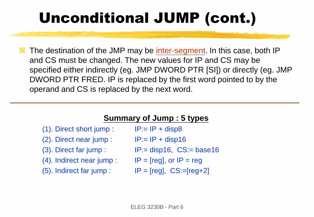
Unconditional JUMP (cont.)
The destination of the JMP may be inter-segment. In this case, both IP
and CS must be changed. The new values for IP and CS may be
specified either indirectly (eg. JMP DWORD PTR [SI]) or directly (eg. JMP
DWORD PTR FRED. IP is replaced by the first word pointed to by the
operand and CS is replaced by the next word.
Summary of Jump : 5 types
(1). Direct short jump : IP:= IP + disp8
(2). Direct near jump : IP:= IP + disp16
(3). Direct far jump : IP:= disp16, CS:= base16
(4). Indirect near jump : IP = [reg], or IP = reg
(5). Indirect far jump : IP = [reg], CS:=[reg+2]
ELEG 3230B - Part 6
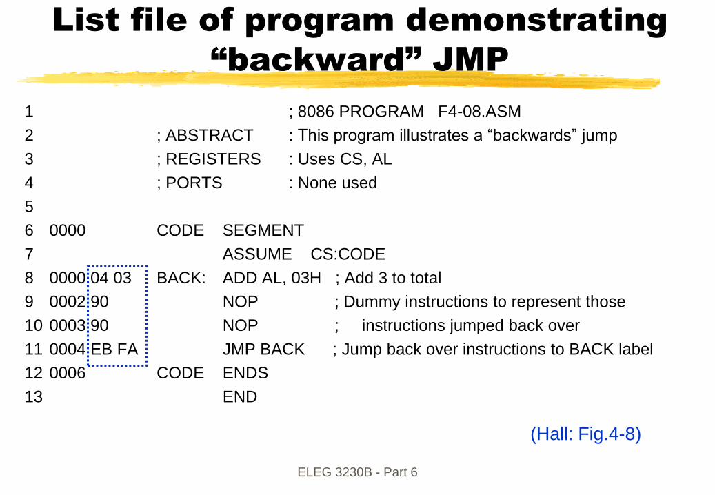
IP=0006+(-6)=0
List file of program demonstrating
“backward” JMP
1 ; 8086 PROGRAM F4-08.ASM
2 ; ABSTRACT : This program illustrates a “backwards” jump
3 ; REGISTERS : Uses CS, AL
4 ; PORTS : None used
5
6 0000 CODE SEGMENT
7 ASSUME CS:CODE
8 0000 04 03 BACK: ADD AL, 03H ; Add 3 to total
9 0002 90 NOP ; Dummy instructions to represent those
10 0003 90 NOP ; instructions jumped back over
11 0004 EB FA JMP BACK ; Jump back over instructions to BACK label
12 0006 CODE ENDS
13 END
FA=11111010 -> -6 (Hall: Fig.4-8)

ELEG 3230B - Part 6
List file of program demonstrating
“forward” JMP
1 ; 8086 PROGRAM F4-09.ASM
2 ; ABSTRACT : This program illustrates a “forwards” jump
3 ; REGISTERS : Uses CS, AL
4 ; PORTS : None used
5
6 0000 CODE SEGMENT
7 ASSUME CS:CODE
8 0000 EB 03 90 BACK: JMP THERE ; Skip over a series of instructions
9 0003 90 NOP ; Dummy instructions to represent those
10 0004 90 NOP ; Instructions skipped over
11 0005 B8 0000 THERE: MOV AX, 0000H; Zero accumulator before addition instructions
12 0008 90 NOP ; Dummy instruction to represent continuation of executions
13 0009 CODE ENDS
14 END
IP=0002
(Hall: Fig.4-9)Next IP=0002+03=0005Next IP=0002+03=0005

ELEG 3230B - Part 6
Conditional Jumps
Only short jump (ie the jump destination is specified by an 8-bit signed
offset which is added to the IP) is possible for the conditional jump
instructions of the 8088/8086. Register names cannot be used as the
operand of a conditional jump instruction.
To perform a conditional jump outside the 8-bit offset range, it is
necessary to combine a conditional short jump with an unconditional jump.
The set of conditional jumps instructions cover all the possible
combinations of zero, carry, overflow, sign and parity flags in the FLAGS
register.
In addition to testing for the various combinations of the C, O, S, Z, and P
flags, there is an instruction to test if the CX register is zero.

ELEG 3230B - Part 6
8086 Conditional Jump Instructions
MNEMONIC CONDITION TESTED "JUMP IF …"
JA/JNBE (CF or ZF)=0 above/not below nor equal JAE/JNB CF=0 above or equal/not below JB/JNAE CF=1 below/not above nor equal JBE/JNA (CF or ZF)=1 below or equal/not above JC CF=1 carry JE/JZ ZF=1 equal/zero JG/JNLE ((SF xor OF) or ZF)=0 greater/not less nor equal JGE/JNL (SF xor OF)=0 greater or equal/not less JL/JNGE (SF xor OF)=1 less/not greater nor equal JLE/JNG ((SF xor OF) or ZF)=1 less or equal/not greater JNC CF=0 not carry JNE/JNZ ZF=0 not equal/not zero JNO OF=0 not overflow JNP/JPO PF=0 not parity/parity odd JNS SF=0 not sign JO OF=1 overflow JP/JPE PF=1 parity/parity equal JS SF=1 sign JCXZ CX=0 Jump if CX=0 JECXZ ECX=0 Jump if ECX=0 (386
Note:
“above” and “below” refer to the relationship of two unsigned values;
“greater” and “less” refer to the relationship of two signedvalues.

ELEG 3230B - Part 6
Ex.: Reading ASCII code when a
strobe is present
FLOWCHART
PSEUDOCODE
REPEAT
READ KEYPRESSED STROBE
UNTIL STROBE = 1
READ ASCII CODE FOR KEY PRESSED
STROBE=1
START
READ STROBE
READASCII CODE
A
NO
YES

ELEG 3230B - Part 6
Assembly language for Reading ASCII
code when a strobe is present
1 ; 8086 PROGRAM F4-20C.ASM
2 ; ABSTRACT : Program to read ASCII code after a strobe signal
3 ; is sent from a keyboard
4 ; REGISTERS : Uses CS, DX, AL
5 ; PORTS : Uses FFFAH - Strobe signal input on LSB
6 ; FFF8H - ASCII data input port
7
8 0000 CODE SEGMENT
9 ASSUME CS:CODE
10 0000 BA FFFA MOV DX, 0FFFAH ; Point DX at strobe port
11 0003 EC LOOK_AGAIN: IN AL, DX ; Read keyboard strobe
12 0004 24 01 AND AL, 01 ; Mask extra bits and set flags
13 0006 74 FB JZ LOOK_AGAIN ;If strobe is low then keep looking
14 0008 BA FFF8 MOV DX, 0FFF8H ; else point DX at data port
15 000B EC IN AL, DX ; Read in ASCII code
16 0000C CODE ENDS
17 END
FB=11111011 -> -5

ELEG 3230B - Part 6
Loops
The 8088/8086 has 3 instructions which are designed for performing asection of code for a fixed number of times:
LOOP d;
LOOPE/LOOPZ d;
LOOPNE/LOOPNZ d;
The operand used in loop is a signed 8-bit offset, usually specified by alabel in assembly language.
LOOP decrements CX and checks if CX is zero. If it isn‟t, LOOP jumps(short) to the specified destination.
LOOPE is similar to LOOP except that an additional test is performed.LOOPE decrements CX and checks to see if CX is zero and if the zeroflag is set. LOOPE will only jump if both CX is non zero and the zero flagis set.
LOOPNZ is also similar. LOOPNZ decrements CX and tests to see if CXis zero and the zero flag is zero. LOOPNZ will only jump if both CX is nonzero and Z is nonzero.
Loops may be nested (loops within loops) and the STACK is often used tostore and recover the counter register of the outer loops.
LOOP DEC CX JNZ

ELEG 3230B - Part 6
Procedures and Modular
Programming
Procedures are grouped sequences of instructions which usually perform
a specific function (e.g. find the mean of several numbers, wait for a given
duration, ...) and which can be used at different points in the main
program.
Advantage of using procedures include:
allows the program to be broken down to simpler modules
saves memory space and effort in writing the program
more readable programs, allowing future program maintenance and easier
debugging
Disadvantage of using too many procedures includes
greater program overhead and hence slower programs

ELEG 3230B - Part 6
Procedures and Modular
Programming (cont.)
Procedures are executed using the CALL instruction
CALL has an operand which is usually the label of the start address of the
procedure, through register, direct and indirect addressing modes may be
used. CALL can start procedures which are near (in the same segment) or
far (in a different segment), and assembler directives WORD PTR or
DWORD PTR are used with CALL to specify whether to replace only IP or
both IP and CS.
CALL differs fundamentally from the JMP instruction since it automatically
PUSHES some register contents onto the STACK before entering the
procedure.

ELEG 3230B - Part 6
Procedures
Assemblers usually provide special directives to identify procedures in order to allow linking of procedures from different source codes.
The start of a procedure is identified by its name in the label field followed by the PROC directive, followed by the type of procedure (ie NEAR or FAR). The end of the procedure is identified by the ENDP directive.
Example:
DELAYS PROC NEAR
MOV CX,1000H
FRED: NOP
LOOP FRED
RET ;returns from procedure by retrieve IP from stack
ENDP
For NEAR procedures (i.e. the procedure is in the same segment), CALLsaves the contents of IP onto the stack before entering the procedure and RET restores the IP to return to the main program.
A CALL to a FAR procedure (i.e. a procedure in a different segment) involve saving both the IP and CS registers onto the stack before the new values of IP and CS are loaded with the start address of the procedure.

ELEG 3230B - Part 6
Stack Diagram
For near CALL For far CALL
Stack in memory
70050h
7004Fh
7004Eh
7004Dh
7004Ch
SP Initialized
to Here - SP=0050H
SP Points Here
After Near CALL
SP=004EH
Stack Segment
BASE - 70000H
SS= 7000H
IP High
IP Low
Stack in memory
70050h
7004Fh
7004Eh
7004Dh
7004Ch
SP Initialized
to Here - SP=0050H
SP Points Here
After Far CALL
Stack Segment
BASE - 70000H
SS= 7000H
CS High
CS Low
IP High
IP Low

ELEG 3230B - Part 6
Using PUSH and POP instructions
MULTO PROC NEAR
PUSHF
PUSH AX
PUSH BX
PUSH CX
.
.
POP CX
POP BX
POP AX
POPF
RET
MULTO ENDP
Effect on stack and stack pointerInstruction sequence
Stack in memorySP
Before CALL 0050h
After CALL 004Eh
After PUSHF 004Ch
After PUSH AX 004Ah
After PUSH BX 0048h
After PUSH CX 0046h
IP High
IP Low
FLAG High
FLAG Low
AH
AL
BH
BL
CH
CL
SP
After RET 0050h
After POPF 004Eh
After POP AX 004Ch
After POP BX 004Ah
After POP CX 0048h
Before POP CX

ELEG 3230B - Part 6
Interrupt Instructions
The program can generate a software interrupt using the INT or INTOinstructions.
Interrupts are similar to Procedures except that the STACK is used to store more items. When the microprocessor encounters an interrupt,it
(1) PUSH the FLAGS onto the STACK
(2) CLEAR the T and I flags
(3) PUSH CS onto the STACK
(4) Fetch the new value of CS from the interrupt vector
(5) PUSH IP onto the STACK
(6) Fetch the new value for IP from the interrupt vector
(7) Run instruction starting at the new value of CS:IP
An Interrupt is handled like a CALL to a FAR procedure with a PUSHFprior to call.
INT instruction: 2 bytes
CALL instruction: 5 bytes

ELEG 3230B - Part 6
Interrupt Vector Table
The 8-bit operand after the INT instruction specifies the type of interrupt.
The address of the interrupt handling procedures is stored in a table of
interrupt vectors at the start of memory, and can be derived by multiplying
the interrupt vector by 4.
The functions of interrupts 0 to 31 are reserved by Intel for special
functions for the 8086-Pentium. The functions of interrupts 32 onwards
may the user defined.
Note : INT instruction : 2 bytes
CALL instruction: 5 bytes
Some of the interrupt functions specified by Intel differ from the actual
interrupt functions which are implemented on the IBM PC. Interrupt
functions specified by Intel are listed below:

ELEG 3230B - Part 6
Interrupt Vector Table (Cont.)
VectorNumber
Address Microprocessor Function
0 0H-3H 8086-80486/Pentium Divide error1 4H-7H 8086-80486/Pentium Single step2 8H-BH 8086-80486/Pentium NMI (hardware interrupt)3 CH-FH 8086-80486/Pentium Breakpoint4 10H-13H 8086-80486/Pentium Interrupt on overflow5 14H-17H 80286-80486/Pentium BOUND interrupt6 18H-1BH 80286-80486/Pentium Invalid opcode7 1CH-1FH 80286-80486/Pentium Coprocessor emulation interrupt8 20H-23H 80386-80486/Pentium Double fault9 24H-27H 80386 Coprocessor segment overrun10 28H-2BH 80386-80486/Pentium Invalid task state segment11 2CH-2FH 80386-80486/Pentium Segment not present12 30H-33H 80386-80486/Pentium Stack fault13 34H-37H 80386-80486/Pentium General protection fault14 38H-3BH 80386-80486/Pentium Page fault15 3CH-3FH Reserved*16 40H-43H 80286-80486/Pentium Floating-point error17 44H-47H 80486SX Alignment check interrupt18 48H-4BH Pentium Machine check exception19-31 4CH-7FH 8086-80486/Pentium Reserved*32-255 80H-3FFH 8086-80486/Pentium User interrupts
(Brey‟s Table 6-4)

ELEG 3230B - Part 6
Memory Address
Table Entry
Vector Definition
3FE CS 255
3FC IP 255
Vector 25510
82 CS 32
80 IP 32
Vector 3210
7E CS 31
7C IP 31
Vector 3110
16 CS 5
14 IP 5
Vector 5
12 CS 4
10 IP 4
Vector 4 – Overflow
0E CS 3
0C IP 3
Vector 3 - Breakpoint
0A CS 2
08 IP 2
Vector 2 - NMI
06 CS 1
04 IP 1
Vector 1 – Single Step
02 CS Value – Vector 0 (CS 0)
00 IP Value – Vector 0 (IP 0)
Vector 0 – Divide Error
2 Bytes
User Available
Reserved
Interrupt Vector

ELEG 3230B - Part 6
Interrupt Assignments on the IBM
PC and compatibles
To return to DOS, assembler programs on IBM PCs must end with INT 21.
Register AH should contain 4CH to specify the DOS terminate functions.Number Function
0 Divide error1 Single step (debug)2 Nonmaskable interrupt pin3 Breakpoint4 Arithmetic overflow5 Print screen key and BOUND instruction6 Illegal instruction error7 Coprocessor not present interrupt8 Clock tick (hardware) (Approximately 18.2 Hz)9 Keyboard (hardware)A Hardware interrupt 2 (system bus) (cascade in AT)B-F Hardware interrupt 3-7 (system bus)10 Video BIOS11 Equipment environment12 Conventional memory size13 Direct disk service14 Serial COM port service15 Miscellaneous service16 Keyboard service17 Parallel port LPT service18 ROM BASIC19 Reboot1A Clock service1B Control-bread handler1C User timer service1D Pointer for video parameter table1E Pointer for disk drive parameter table1F Pointer for graphics character pattern table20 Terminate program21 DOS service22 Program termination handler23 Control C handler24 critical error handler25 Read disk26 Write disk27 Terminate and stay resident28 DOS idle2F Multiplex handler70-770 Hardware interrupts 8-15 (AT style computer)
(Brey‟s Table 6-5)

ELEG 3230B - Part 6
Interrupt Instructions
Mnemonic Meaning Format Operation Flags Affected
CLI Clear interrupt flag CLI 0 (IF) IF STI Set interrupt flag STI 1 (IF) IF
INT n Type n software interrupt INT n (Flags) ((SP) – 2) 0 TF, IF (CS) ((SP) – 4)
(2+4n) (CS) (IP) ((SP) – 6)
(4n) (IP)
TF, IF
IRET Interrupt return IRET ((SP)) (IP) ((SP) + 2) (CS) ((SP) + 4) (Flags) (SP) + 6 (SP)
All
INTO Interrupt on overflow INTO INT 4 steps TF, IF HLT Halt HLT Wait for an external
Interrupt or reset to occur None
WAIT Wait WAIT Wait for TEST input to go active
None
SP: stack pointer

ELEG 3230B - Part 6
Internal state of the 8088 after
initialization
CPU COMPONENT CONTENT
Flags Clear Instruction Pointer 0000h CS Register FFFFh DS Register 0000h SS Register 0000h ES Register 0000h Queue Empty
Q: So where is the first instruction located after initialization?