part 5 - aehighschool.com olampiad/fizik/jahani... · time available: 5 hours read this first : 1....
TRANSCRIPT

141
PART 5
Experimental Competition
Exam commission page 142Problems in English page 143The men behind the equipment page 153Model answers in English page 154Marking form (translated to English) page 165The last preparations (photos) page 171Examples of translated texts page 172Examples of student’s papers page 181Photos from the experim. competition page 190

142
Preparation of the experimental competition was carried out by:
Børge Holme Tom Henning Johansen Arnt Inge Vistnes
Commission for the Experimental Competition:
Tom Henning JohansenBørge Holme
Svenn L. AndersenCarl AngellBjørn Berre#
Jan Kåre BordingMagne Guttormsen
Vidar HansenTor Haugset
Geir Helgesen§
Jan HoltetRandi HaakenaasenTrond Myklebust
Jon Samset§
fromUniversity of Oslo, Oslo
§ : Institute for Energy Technology, Kjeller# : Agricultural University of Norway, Ås
Phot
o: G
eir H
olm
143
27th INTERNATIONAL PHYSICS OLYMPIADOSLO, NORWAY
EXPERIMENTAL COMPETITIONJULY 4 1996
Time available: 5 hours
READ THIS FIRST :1. Use only the pen provided.2. Use only the marked side of the paper.3. No points will be given for error estimates except in 2c. However, it is ex-
pected that the correct number of significant figures are given.4. When answering problems, use as little text as possible. You get full credit
for an answer in the form of a numerical value, a drawing, or a graph withthe proper definition of axes, etc.
5. Write on top of every sheet in your report:• Your candidate number (IPhO ID number)• The section number• The number of the sheet
6. Write on the front page the total number of sheets in your report, includinggraphs, drawings etc.
7. Ensure to include in your report the last page in this set used for answeringsection 2a and 3b, as well as all graphs requested.
SAFETY HAZARD: Be careful with the two vertical blades on the largestand. The blades are sharp!
This set of problems consists of 10 pages.

144
SUMMARY
The set of problems will cover a number of topics in physics. First, some me-chanical properties of a physical pendulum will be explored, and you should beable to determine the acceleration of gravity. Then, magnetic forces are addedto the pendulum. In this part the magnetic field from a permanent magnet ismeasured using an electronic sensor. The magnetic moment of a small perma-nent magnet will be determined. In addition, a question in optics in relation tothe experimental setup will be asked.
INSTRUMENTATION
The following equipment is available (see Figure 1):
A Large aluminium standB Threaded brass rod with a tiny magnet in one end (painted
white) (iron in the other).C 2 Nuts with a reflecting surface on one sideD Oscillation period timer (clock) with digital displayE Magnetic field (Hall) probe, attached to the large standF 9 V batteryG Multimeter, Fluke model 75H 2 LeadsI Battery connectorJ Cylindrical stand made of PVC (grey plastic material)K Threaded rod with a piece of PVC and a magnet on the topL Small PVC cylinder of length 25.0 mm (to be used as a spacer)M Ruler
If you find that the large stand wiggles, try to move it to a different posistion onyour table, or use a piece of paper to compensate for the non-flat surface.
The pendulum should be mounted as illustrated in Figure 1. The long threadedrod serves as a physical pendulum, hanging in the large stand by one of thenuts. The groove in the nut should rest on the two vertical blades on the largestand, thus forming a horizontal axis of rotation. The reflecting side of the nutis used in the oscillation period measurement, and should always face towardthe timer.
The timer displays the period of the pendulum in seconds with an uncertaintyof ±1 ms. The timer has a small infrared light source on the right-hand side ofthe display (when viewed from the front), and an infrared detector mounted

145
close to the emitter. Infrared light from the emitter is reflected by the mirrorside of the nut. The decimal point lights up when the reflected light hits the de-tector. For proper detection the timer can be adjusted vertically by a screw (seeN in Figure 1). Depending on the adjustment, the decimal point will blink ei-ther once or twice each oscillation period. When it blinks twice, the displayshows the period of oscillation, T. When it blinks once, the displayed number is2T. Another red dot appearing after the last digit indicates low battery. If bat-tery needs to be replaced, ask for assistance.
The multimeter should be used as follows:Use the “VΩ” and the “COM” inlets. Turn the switch to the DC voltage setting.The display then shows the DC voltage in volts. The uncertainty in the instru-ment for this setting is ±(0.4%+1 digit).
Figure 1. The instrumentation used.
SAFETY HAZARD: Be careful with the two vertical blades on the largestand. The blades are sharp!
Phot
o: G
eir H
olm

146
THE PHYSICAL PENDULUM
A physical pendulum is an extended physical object of arbitrary shape that canrotate about a fixed axis. For a physical pendulum of mass M oscillating abouta horizontal axis a distance, l, from the centre of mass, the period, T, for smallangle oscillations is
Tg
IM l
l= +2π(1)
Here g is the acceleration of gravity, and I is the moment of inertia of the pen-dulum about an axis parallel to the rotation axis but through the centre of mass.
Figure 2 shows a schematic drawing of the physical pendulum you will be us-ing. The pendulum consists of a cylindrical metal rod, actually a long screw,having length L, average radius R, and at least one nut. The values of variousdimensions and masses are summarised in Table 1. By turning the nut you canplace it at any position along the rod. Figure 2 defines two distances, x and l,that describe the position of the rotation axis relative to the end of the rod andthe centre of mass, respectively.
Figure 2: Schematic drawing of the pendulumwith definition of important quantities.

147
RodLength L (400.0 ± 0.4) mmAverage radius R (4.4 ± 0.1) mmMass MROD (210.2 ± 0.2) 10-3 kgDistance between screw threads (1.5000 ± 0.0008) mm
NutHeight h (9.50 ± 0.05) mmDepth of groove d (0.55 ± 0.05) mmMass MNUT (4.89 ± 0.03) 10-3 kg
Table 1: Dimensions and weights of the pendulum
A reminder from the front page: No points will be given for error estimates ex-cept in 2c. However, it is expected that the correct number of significant fig-ures are given.
Section 1 : Period of oscillation versus rotation axis position(4 marks)
a) Measure the oscillation period, T, as a function of the position x, and presentthe results in a table.
b) Plot T as a function of x in a graph. Let 1 mm in the graph correspond to1 mm in x and 1 ms in T. How many positions give an oscillation period equalto T = 950 ms, T = 1000 ms and T = 1100 ms, respectively?
c) Determine the x and l value that correspond to the minimum value in T.
Section 2 : Determination of g (5 marks)
For a physical pendulum with a fixed moment of inertia, I, a given period, T,may in some cases be obtained for two different positions of the rotation axis.Let the corresponding distances between the rotation axis and the centre ofmass be l1 and l2 . Then the following equation is valid:
l l IM1 2 = (2)

148
a) Figure 6 on the last page in this set illustrates a physical pendulum with anaxis of rotation displaced a distance l1 from the centre of mass. Use the infor-mation given in the figure caption to indicate all positions where a rotation axisparallel to the drawn axis can be placed without changing the oscillation period.
b) Obtain the local Oslo value for the acceleration of gravity g as accurately aspossible. Hint: There are more than one way of doing this. New measurementsmight be necessary. Indicate clearly by equations, drawings, calculations etc.the method you used.
c) Estimate the uncertainty in your measurements and give the value of g witherror margins.
Section 3 : Geometry of the optical timer (3 marks)
a) Use direct observation and reasoning to characterise, qualitatively as well asquantitatively, the shape of the reflecting surface of the nut (the mirror). (Youmay use the light from the light bulb in front of you).
Options (several may apply):1. Plane mirror2. Spherical mirror3. Cylindrical mirror4. Cocave mirror5. Convex mirror
In case of 2-5: Determine the radius of curvature.
b) Consider the light source to be a point source, and the detector a simple pho-toelectric device. Make an illustration of how the light from the emitter is re-flected by the mirror on the nut in the experimantal setup (side view and topview). Figure 7 on the last page in this set shows a vertical plane through thetimer display (front view). Indicate in this figure the whole region where thereflected light hits this plane when the pendulum is vertical.
Section 4 : Measurement of magnetic field (4 marks)
You will now use an electronic sensor (Hall-effect sensor) to measure magneticfield. The device gives a voltage which depends linearly on the vertical fieldthrough the sensor. The field-voltage coefficient is ∆V / ∆B = 22.6 V/T (Volt/Tesla). As a consequence of its design the sensor gives a non-zero voltage(zero-offset voltage) in zero magnetic field. Neglect the earth’s magnetic field.
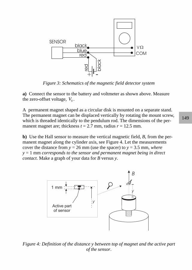
149
Figure 3: Schematics of the magnetic field detector system
a) Connect the sensor to the battery and voltmeter as shown above. Measurethe zero-offset voltage, V0 .
A permanent magnet shaped as a circular disk is mounted on a separate stand.The permanent magnet can be displaced vertically by rotating the mount screw,which is threaded identically to the pendulum rod. The dimensions of the per-manent magnet are; thickness t = 2.7 mm, radius r = 12.5 mm.
b) Use the Hall sensor to measure the vertical magnetic field, B, from the per-manent magnet along the cylinder axis, see Figure 4. Let the measurementscover the distance from y = 26 mm (use the spacer) to y = 3.5 mm, wherey = 1 mm corresponds to the sensor and permanent magnet being in directcontact. Make a graph of your data for B versus y.
Figure 4: Definition of the distance y between top of magnet and the active partof the sensor.
150
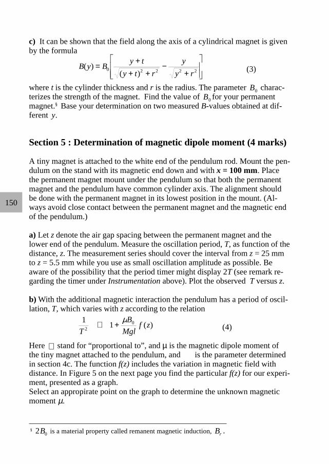
c) It can be shown that the field along the axis of a cylindrical magnet is givenby the formula
B y B y ty t r
yy r
( )( )
= ++ +
−+
0 2 2 2 2 (3)
where t is the cylinder thickness and r is the radius. The parameter B0 charac-terizes the strength of the magnet. Find the value of B0 for your permanentmagnet.§ Base your determination on two measured B-values obtained at dif-ferent y.
Section 5 : Determination of magnetic dipole moment (4 marks)
A tiny magnet is attached to the white end of the pendulum rod. Mount the pen-dulum on the stand with its magnetic end down and with x = 100 mm. Placethe permanent magnet mount under the pendulum so that both the permanentmagnet and the pendulum have common cylinder axis. The alignment shouldbe done with the permanent magnet in its lowest position in the mount. (Al-ways avoid close contact between the permanent magnet and the magnetic endof the pendulum.)
a) Let z denote the air gap spacing between the permanent magnet and thelower end of the pendulum. Measure the oscillation period, T, as function of thedistance, z. The measurement series should cover the interval from z = 25 mmto z = 5.5 mm while you use as small oscillation amplitude as possible. Beaware of the possibility that the period timer might display 2T (see remark re-garding the timer under Instrumentation above). Plot the observed T versus z.
b) With the additional magnetic interaction the pendulum has a period of oscil-lation, T, which varies with z according to the relation
1 120
TB
Mglf z∝ +
µ( ) (4)
Here ∝ stand for “proportional to”, and µ is the magnetic dipole moment ofthe tiny magnet attached to the pendulum, and is the parameter determinedin section 4c. The function f(z) includes the variation in magnetic field withdistance. In Figure 5 on the next page you find the particular f(z) for our experi-ment, presented as a graph.Select an appropirate point on the graph to determine the unknown magneticmoment µ.
§ 2 0B is a material property called remanent magnetic induction, Br .

151
z (mm)0 5 10 15 20 25 30
f(z)
0
10
20
30
40
50
60
Figure 5. Graph of the dimension-less function f(z) used in section 5b.

152
Figure 6. For use in section 2a. Mark all positions where a rotation axis(orthogonal to the plane of the paper) can be placed without changing theoscillation period. Assume for this pendulum (drawn on scale, 1:1) thatI/M = 2100 mm2. (Note: In this booklet the size of this figure is about 75% ofthe size in the original examination paper.)
Figure 7. For use in section 3b. Indicate the whole area where the reflectedlight hits when the pendulum is vertical.
Include this page in your report!

153
The men behind the equipment
The equipment for the practical competition was constructed and manufacturedat the Mechanics Workshop at the Department of Physics, University of Oslo(see picture below, from left to right: Tor Enger (head of the Mechanics Workshop),Pål Sundbye, Helge Michaelsen, Steinar Skaug Nilsen, and Arvid Andreassen).
The electronic timer was designed and manufactured by Efim Brondz,Department of Physics, University of Oslo (see picture below). About 40.000soldering points were completed manually, enabling the time-recording duringthe exam to be smooth and accurate.
Phot
o: G
eir H
olm
Phot
o: G
eir H
olm

154
27th INTERNATIONAL PHYSICS OLYMPIADOSLO, NORWAY
Model Answerfor the
EXPERIMENTAL COMPETITIONJULY 4 1996
These model answers indicate what is required from the candidates to get the maximum scoreof 20 marks. Some times we have used slightly more text than required; paragraphs written initalic give additional comments. This practical exam will reward students with creativity,intuition and a thorough understanding of the physics involved.
Alternative solutions regarded as less elegant or more time consuming are printed inframes like this with white background.
Anticipated INCORRECT answers are printed on grey background and are included topoint out places where the students may make mistakes or approximations without beingaware of them.
Section 1:1a) Threads are 1.50 mm/turn. Counted turns to measure position x.
Turn no. 0 10 20 30 40 50 60 70 80 90 100
x [mm] 10.0 25.0 40.0 55.0 70.0 85.0 100.0 115.0 130.0 145.0 160.0T [ms] 1023 1005 989 976 967 964 969 987 1024 1094 1227
Turn no. 110 120 46 48 52 54
x [mm] 175.0 190.0 79.0 82.0 88.0 91.0T [ms] 1490 2303 964 964 964 965
Candidate: IPhO ID Question: 1 Page 1 of 11

155
1b) Graph: T(x), shown above.
T = 950 ms: NO positionsT =1000 ms: 2 positionsT =1100 ms: 1 position
If the answer is given as corresponding x-values, and these reflect the number ofpositions asked for, this answer will also be accepted.
Candidate: IPhO ID Question: 1 Page 2 of 11

156
1c) Minimum on graph: x = 84 mm, (estimated uncertainty 1 mm)
By balancing the pendulum horizontally: l = 112.3 mm + 0.55 mm = 113 mm
ALTERNATIVE 1c-1:
xM L M h
MM
MxCM
ROD NUT NUT=−
+2
= 197.3 mm for x = 84 mm
gives l = 197.3 mm - 84 mm = 113 mmM = MROD + MNUT, h = 8.40 mm = height of nut minus two grooves.
INCORRECT 1c-1: Assuming that the centre of mass for the pendulum coincides with themidpoint, L/2, of the rod gives l = L/2 - x = 116 mm.
(The exact position of the minimum on the graph is x = 84.4 mm. with l = 112.8 mm)
Section 2:
2a) lI
Ml21
2210060
35= = =mm
mmmm
See also Figure 6 on the next page
Candidate: IPhO ID Question: 1 + 2 Page 3 of 11

157
Figure 6. For use in section 2a. Mark all positions where a rotation axis (orthogonal to theplane of the paper) can be placed without changing the oscillation period. Assume for thispendulum (drawn on scale, 1:1) that I/M = 2100 mm2. (Note: In this booklet the size of thisfigure is about 75% of the size in the original examination paper.)
Figure 7. For use in section 3b. Indicate the whole area where the reflected light hits whenthe pendulum is vertical.
Include this page in your report!
Candidate: IPhO ID Question: 2 Page 4 of 11
158
2b) Simple method with small uncertainty: Inverted pendulum.
Equation (1) + (2) ⇒ = = + ⇔ = +T Tg
l l gT
l l1 2 1 2
2
12 1 2
2 4π π( )
NOTE: Independent of I/M !Used both nuts with one nut at the end to maximise l1 + l2. Alternately adjusted nut
positions until equal periods T1 = T2 :
T1 = T2 = 1024 ms.Adding the depth of the two grooves to the measured distance between nuts:l1 + l2 = (259.6 + 2 . 0.55) mm = 0.2607 m
gT
l l= + =⋅ ⋅
=4 4 31416 0 2607
9 8152
12 1 2
2π( )
. ..
m(1.024s)
m / s22
ALTERNATIVE 2b-1: Finding I(x). Correct but time consuming.It is possible to derive an expression for I as a function of x. By making sensibleapproximations, this gives:
I xM
L MM
L hx
MM
NUT ROD( )= +
+−
2 2
12 2
which is accurate to within 0.03 %. Using the correct expression for l as a function of x:
l x x xM L M h
MM
MxCM
ROD NUT ROD( ) = − =−
−2
= 195.3 mm - 0.9773x,
equation (1) can be used on any point (x, T) to find g. Choosing the point(85 mm, 964 ms) gives:
gT
I xM l x
l x=⋅
+
=
⋅ ⋅=
4 4 31416 0 23119 818
2
2
2π ( )( )
( ). .
.m
(0.964s)m / s2
2
Candidate: IPhO ID Question: 2 Page 5 of 11

159
Using the minimum point on the graph in the way shown below is wrong, since the
curve in 1b) , T xg
I xM l x
l x( ) ( )( )
( )=⋅
+2π
with I(x)/M and l(x) given above, describes a
continuum of different pendulums with changing I(x) and moving centre of mass.
Equation (1): Tg
IMl
l= +2π describes one pendulum with fixed I, and does not apply
to the curve in 1b).
INCORRECT 2b-1: At the minimum point we have from Equation (2) and 1c):
l l l IM1 2 113 1= = = = ±( ) mm Equation (1) becomes
Tg
ll
lg
lmin = + =2 2
22π π
and
gl
T= =
⋅ ⋅=
8 8 31416 01139 60
2
2
2π
min
. ..
m(0.964s)
m / s22
Another source of error which may accidentally give a reasonable value is using thewrong value l = (116 ± 1)mm from «INCORRECT 1c-1»:
INCORRECT 2b-2: g lT
= =⋅ ⋅
=8 8 31416 01160 964
9 862
2
2
2π
min
. .( . )
.m
sm / s2
Totally neglecting the mass of the nut but remembering the expression for the moment ofinertia for a thin rod about a perpendicular axis through the centre of mass, I = ML2/12,gives from equation (2) for the minimum point: l2 = I/M = L2/12 = 0.01333 m2. Thisvalue is accidentally only 0.15% smaller than the correct value for I(x)/M at the mini-mum point on the curve in 1b):
I xM
L MM
L h xM
MNUT ROD( . )
.=
= + + −
=84 43
12 20 01335
2 2mmm 2
.
Candidate: IPhO ID Question: 2 Page 6 of 11
(continued on next page)

160
Neglecting the term M
ML hNUT +
−
2
84 432
. mm = 0.00033 m2 is nearly compensated by
omitting the factor M
MROD =0.977. However, each of these approximations are of the
order of 2.5 %, well above the accuracy that can be achieved.
INCORRECT 2b-3: At the minimum point equation (2) gives lIM
L22
12= = . Then
Tg
lg
Lg
Lmin = = =
2 2 2 212
23
π π π and
( )g
LT
= =⋅ ⋅
⋅=
43
4 31416 0 4000
17321 0964981
2
2
2
2π
min
. .
. ..
m
sm / s2
2c) Estimating uncertainty in the logarithmic expression for g:
Let S l l g ST
≡ + ⇒ =1 2
2
24π
∆ ∆S T= =0 3 1. mm ms
∆ ∆ ∆gg
SS
TT
=
+ −
=
+ ⋅
2 2 2 2
20 3
260 72
11024
..mm
mmms
ms
= + = =( . ) ( . ) . .0 0012 0 0020 0 0023 0 23%2 2
∆g = ⋅ =0 0023 9 815 0 022. . .m / s m / s2 2
g = ±( . . )982 0 02 m / s2
The incorrect methods INCORRECT 2b-1, 2b-2 and 2b-3 have a similar expressions for gas above. With ∆l = 1 mm in INCORRECT 2b-1 and 2b-2 we get ∆g = 0.09 m/s2.
INCORRECT 2b-3 should have ∆l = 0.3 mm and ∆g = 0.02 m/s2.
Candidate: IPhO ID Question: 2 Page 7 of 11
(cont.)

161
ALTERNATIVE 3 has a very complicated x dependence in g. Instead of differentiatingg(x) it is easier to insert the two values x+∆x and x-∆x in the expression in brackets [ ],thus finding an estimate for ∆[ ] and then using the same formula as above.
(The official local value for g, measured in the basement of the adjacent building to where thepractical exam was held is g = 9.8190178 m/s2 with uncertainty in the last digit.)
Section 3.3a) 3. Cylindrical mirror
4. Concave mirror
Radius of curvature of cylinder, r = 145 mm. (Uncertainty approx. ± 5 mm, not asked for.)
(In this set-up the emitter and detector are placed at the cylinder axis. The radius of curvatureis then the distance between the emitter/detector and the mirror. )
3b) Three drawings, see Figure 7 on page 4 in this Model Answers.
(The key to understanding this set-up is that for a concave cylindrical mirror with a pointsource at the cylinder axis, the reflected light will be focused back onto the cylinder axis as aline segment of length twice the width of the mirror.)
Section 4.4a) Vo = 2.464 V (This value may be different for each set-up.)
4b) Threads are 1.50 mm /turn. Measured V(y) for each turn. Calculated
[ ] [ ]B y V y VBV
V y VVB
( ) ( ) ( ) /= − = −0 0∆∆
∆∆
. (Table not requested)
See graph on next page.
Candidate: IPhO ID Question: 2 + 3 + 4 Page 8 of 11

162
4c)
B B y y t
y t r
y
y r0 2 2 2 2
1
= +
+ +−
+
−
( )( )
The point (11 mm, 48.5 mT) gives B0 = 0.621 T and (20 mm, 16,8 mT) gives B0 = 0.601 T.Mean value: B0 = 0.61 T (This value may vary for different magnets.)
Section 5:
5a) Used the spacer and measured T(z) from z = 25 mm to 5.5 mm. (Table is not requested.)
See plot on next page.
Candidate: IPhO ID Question: 4 + 5 Page 9 of 11
Graph: B(y):
163
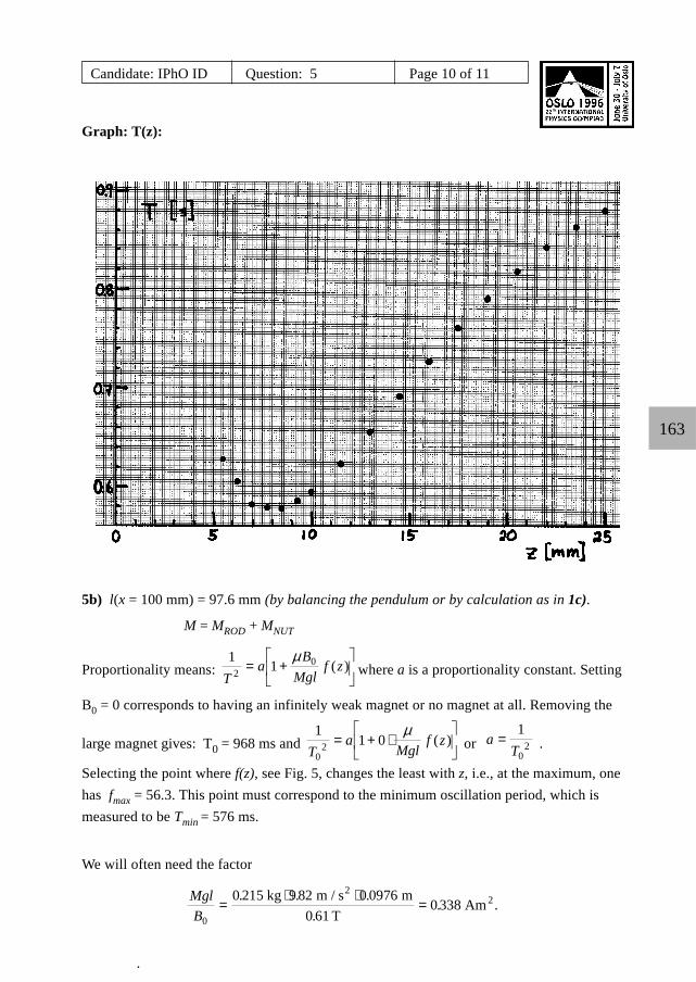
5b) l(x = 100 mm) = 97.6 mm (by balancing the pendulum or by calculation as in 1c).
M = MROD + MNUT
Proportionality means: 1 12
0
Ta
BMgl
f z= +
µ( ) where a is a proportionality constant. Setting
B0 = 0 corresponds to having an infinitely weak magnet or no magnet at all. Removing the
large magnet gives: T0 = 968 ms and 1
1 00
2Ta
Mglf z= + ⋅
µ( ) or a
T=
1
02 .
Selecting the point where f(z), see Fig. 5, changes the least with z, i.e., at the maximum, onehas fmax = 56.3. This point must correspond to the minimum oscillation period, which ismeasured to be Tmin = 576 ms.
We will often need the factor
MglB0
0 215 9 82 0 09760 61
0 338=⋅ ⋅
=. . .
.. .
kg m / s mT
Am2
2
.
Candidate: IPhO ID Question: 5 Page 10 of 11
Graph: T(z):

164
The magnetic moment then becomes
µ =
−
=
−
= ⋅ −MglB f
TTmax0
02 2
21 10338
56 3968576
1 11 10.
..
AmAm
22
ALTERNATIVE 5b-1: Not what is asked for: Using two points to eliminate the
proportionality constant a: Equation (4) or 1 12
0
Ta
BMgl
f z= +
µ( ) gives:
aTB
Mglf z aT
BMgl
f z12 0
1 22 0
21 1+
= +
µ µ( ) ( )
T TB
Mglf z T T
BMgl
f z12
12 0
1 22
22 0
2+ = +µ µ
( ) ( )
[ ]µBMgl
T f z T f z T T01
21 2
22 2
21
2( ) ( )− = −
µ = ⋅−−
MglB
T TT f z T f z0
22
12
12
1 22
2( ) ( )
Choosing two points (z1 = 7 mm, T1 = 580.5 ms) and (z2 = 22 mm, T2 = 841ms). Readingfrom the graph f(z1) = 56.0 and f(z2) = 12.0 we get
µ = ⋅−
⋅ − ⋅= ⋅ −0 338
841 580580 56 0 841 12 0
12 102 2
2 22.
. ..Am Am2 2
Candidate: IPhO ID Question: 5 Page 11 of 11

165
Candidate: Total score: + + + + = Country: Marker’s name: Language: Comment:
Marking Formfor the Experimental Competition at the27th International Physics Olympiad
Oslo, NorwayJuly 4, 1996
To the marker: Carefully read through the candidate’s exam papers and compare withthe model answer. You may use the transparencies (handed out) when checking thegraph in 1b) and the drawing in 2a). When encountering words or sentences thatrequire translation, postpone marking of this part until you have consulted the inter-preter.
Use the table below and mark a circle around the point values to be subtracted. Addvertically the points for each subsection and calculate the score.NB: Give score 0 if the value comes out negative for any subsection.Add the scores for each subsection and write the sum in the ‘Total score’- box at theupper right. Keep decimals all the way.
If you have questions, consult the marking leader. Good luck, and remember that youwill have to defend your marking in front of the team leaders.
(Note: The terms “INCORRECT 2b-1” found in the table for subsection 2c) and similar termselsewhere, refer to the Model Answer, in which anticipated incorrect answers were includedand numbered for easy reference.)

166
Subsection 1a) DeficiencyNo answer
x lacks unitOther than 0 or 1 decimal in x
x does not cover the interval 10 mm - 160 mmT lacks unit
T given with other than 1 or 0.5 millisecond accuracyFewer than 11 measuring points (15 mm sep.). Subtr. up to
Systematic error in x (e.g. if measured from the top of the nut so that thefirst x = 0 mm)
If not aware of doubling of the timer period Other (specify):
Score for subsection 1a: 1.0 -
Subtract1.00.10.10.10.10.10.2
0.20.2
=
Subsection 1b) DeficiencyNo answer
Lacks “x [(m)m]” on horizontal axis1 mm on paper does not correspond to 1 mm in x
Fewer than 3 numbers on horizontal axisLacks “T [(m)s]” on vertical axis
1 mm on paper does not correspond to 1 ms in TFewer than 3 numbers on vertical axis
Measuring points not clearly shown (as circles or crosses)More than 5 ms deviation in more than 2 measuring points on the graph
Wrong answer to the questions (x-values give full score if correct numberof values: 0, 2, 1)
Other (specify):Score for subsection 1b): 1.0 -
Subtract1.00.10.10.10.10.10.10.20.2
0.2
=
Subsection 1c) DeficiencyNo answer
x outside the interval 81 - 87 mm. Subtract up tox lacks unit
x given more (or less) accurately than in whole millimetersl lacks unit
l given more (or less) accurately than the nearest mmWrong formula (e.g. l = 200.0 mm - x ) or something other than l = xCM - x
If it is not possible to see which method was used to find the center of mass Other (specify):
Score for subsection 1c): 2.0 -
Subtract2.00.40.10.30.10.30.60.2
=

167
Subsection 2a) DeficiencyNo answer
If drawn straight (vertical) linesIf points are drawn
Other than 4 regions are drawnInaccurate drawing (> ± 2 mm )
Lacks the values l1 = 60 mm, l2 = 35 mm on figure or text Other (specify):
Score for subsection 2a): 1.5 -
Subtract1.50.40.50.50.30.3
=
Subsection 2b) DeficiencyNo answer
Lacks (derivation of) formula for gFor INVERTED PENDULUM: Lacks figure
Values from possible new measurements not givenIncomplete calculations
If hard to see which method was usedUsed the formula for INVERTED PENDULUM but read l1 and l2 from
graph in 1b) by a horizontal line for a certain TUsed one of the other incorrect methods
Other than 3 (or 4) significant figures in the answerg lacks unit m/s2
Other (specify):Score for subsection 2b): 2.5 -
Subtract2.50.30.20.30.30.4
1.52.00.30.1
=
Subsection 2c) DeficiencyNo answer
Wrong expression for ∆g/g or ∆g. Subtract up toFor INVERTED PENDULUM: If 0.3 mm >∆(l1+l2) > 0.5 mm
For ALTERNATIVE 2c-1: If ∆[] > 0.1 mmFor INCORRECT 2c-1 and 2c-2: If 1 mm > ∆l > 2 mm
For INCORRECT 2c-3: If 0.3 mm > ∆L > 0.4 mmFor all methods: If ∆T ≠ 1 (or 0.5) ms
Error in the calculation of ∆gLacks answer including g ± ∆g with 2 decimals
g ± ∆g lacks unit Other (specify):
Score for subsection 2c): 2.5 -
Subtract2.50.50.20.20.20.20.20.20.20.1
=

168
Subsection 3a) DeficiencyNo answer
Lacks point 3. cylindrical mirrorLacks point 4. concave mirror
Includes other points (1, 2 or 5), subtract per wrong point:Lacks value for radius of curvature
If r < 130 mm or r > 160 mm, subtract up toIf r is given more accurately than hole millimeters
Other (specify):Score for subsection 3a): 1.0 -
Subtract1.00.30.30.30.40.20.2
=
Subsection 3b) DeficiencyNo answer
Lacks side view figureErrors or deficiencies in the side view figure. Subtract up to
Lacks top view figureErrors or deficiencies in the top view figure. Subtract up to
Drawing shows light focused to a pointDrawing shows light spread out over an ill defined or wrongly shaped
surfaceLine/surface is not horizontal
Line/point/surface not centered symmetrically on detectorLine/point/surface has length different from twice the width of the nut
(i.e. outside the interval 10 - 30 mm) Other (specify):
Score for subsection 3b): 2.0 -
Subtract2.00.60.40.60.40.3
0.30.20.2
0.1
=
169
Subsection 4a) DeficiencyNo answer
Vo lacks unit VLess than 3 decimals in Vo
Incorrect couplings (would give Vo < 2.3 V or Vo > 2.9 V) Other (specify):
Score for subsection 4a): 1.0 -
Subtract1.00.10.10.8
=
Subsection 4b) DeficiencyNo answer
Forgotten Vo or other errors in formula for BLacks “y [(m)m]” on horizontal axis
Fewer than 3 numbers on horizontal axisLacks “B [(m)T]” on vertical axis
Fewer than 3 numbers on vertical axisFewer than 9 measuring points. Subtract up to
Measuring points do not cover the interval 3.5 mm - 26 mmMeasuring points not clearly shown (as circles or crosses)
Error in data or unreasonably large spread in measuring points. Subtractup to
Other (specify):Score for subsection 4b): 1.5 -
Subtract1.50.20.10.10.10.10.20.20.1
0.5
=
Subsection 4c) DeficiencyNo answer
Incorrect formula for BoIf used only one measuring point
If used untypical points on the graphErrors in calculation of mean value for Bo
Bo lacks unit TOther than two significant figures in (the mean value of) Bo
Bo < 0.4 T or Bo > 0.7 T. Subtract up to Other (specify):
Score for subsection 4c): 1.5 -
Subtract1.50.30.40.30.20.10.20.2
=
170
Subsection 5a) DeficiencyNo answer
Lacks “z [(m)m]” on horizontal axisFewer than 3 numbers on horizontal axis
Lacks “T [(m)s]” on vertical axisFewer than 3 numbers on vertical axis
Fewer than 8 measuring points. Subtract up toMeasuring points not clearly shown (as circles or crosses)
Measuring points do not cover the interval 5.5 mm - 25 mmError in data (e.g. plotted 2T instead of T) or unreasonably large spread
in measuring points. Subtr. up to Other (specify):
Score for subsection 5a): 1.0 -
Subtract1.00.10.10.10.10.20.10.2
0.5
=
Subsection 5b) DeficiencyNo answer
Forgotten center of mass displacement in l (used l = 100 mm)Used ALTERNATIVE 5b-1
Lacks method for finding the proportionality factor aNot found correct proportionality factor a
Used another point than the maximum of f(z)Incorrect reading of f(z)
Used MROD or another incorrect value for MIncorrect calculation of µµ lacks unit (Am2 or J/T)
More than 2 significant figures in µ Other (specify):
Score for subsection 5b): 3.0 -
Subtract3.00.31.02.50.30.10.10.20.30.20.3
=
Total points:
Total for section 1 (max. 4 points):Total for section 2 (max. 5 points):Total for section 3 (max. 3 points):Total for section 4 (max. 4 points):Total for section 5 (max. 4 points):

171
The last preparations
The problem for the experimental competition was discussed by the leaders andthe organizers the evening before the exam. At this meeting the equipment wasdemonstrated for the first time (picture).
After the meeting had agreed on the final text (in English), the problems had tobe translated into the remaining 36 languages. One PC was available for eachnation for the translation process (see picture below). The last nation finishedtheir translation at about 4:30 a.m. in the morning, and the competition startedat 0830. Busy time for the organizers! Examples of the different translationsare given on the following pages.
Photo: Børge Holme
Photo: Børge Holme
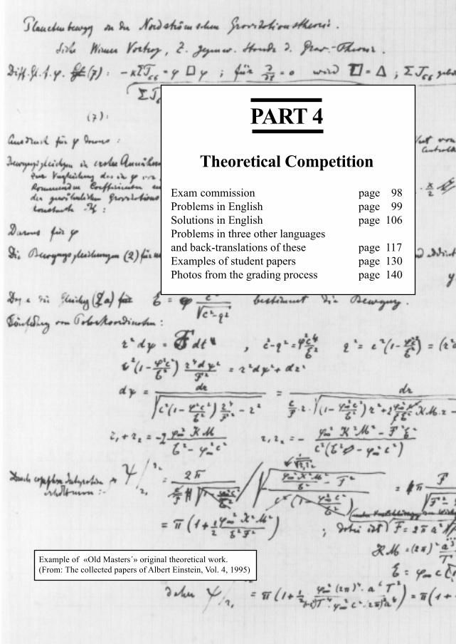
97
PART 4
Theoretical Competition
Exam commission page 98Problems in English page 99Solutions in English page 106Problems in three other languagesand back-translations of these page 117Examples of student papers page 130Photos from the grading process page 140
Example of «Old Masters´» original theoretical work.(From: The collected papers of Albert Einstein, Vol. 4, 1995)

98Per Chr. HemmerChief examiner
Commission for the Theoretical Competiton:
Per Chr. HemmerAlex Hansen
Eivind Hiis HaugeKjell Mork
Kåre OlaussenNorwegian University of Science and Technology, Trondheim
&
Torgeir EngelandYuri Galperin
Anne HoltAsbjørn Kildal
Leif VesethUniversity of Oslo

99
27th INTERNATIONAL PHYSICS OLYMPIADOSLO, NORWAY
THEORETICAL COMPETITIONJULY 2 1996
Time available: 5 hours
READ THIS FIRST :1. Use only the pen provided2. Use only the marked side of the paper3. Each problem should be answered on separate sheets4. In your answers please use primarily equations and numbers, and as little text as possible5. Write at the top of every sheet in your report:
• Your candidate number (IPhO identification number)• The problem number and section identification, e.g. 2/a• Number each sheet consecutively
6. Write on the front page the total number of sheets in your report
This set of problems consists of 7 pages.

100
PROBLEM 1
(The five parts of this problem are unrelated)
a) Five 1Ω resistances are connected as shown in the figure. The resistance inthe conducting wires (fully drawn lines) is negligible.
Determine the resulting resistance R between A and B. (1 point)___________________________________________________________________________
b)
A skier starts from rest at point A and slides down the hill, without turning orbraking. The friction coefficient is µ. When he stops at point B, his horizontaldisplacement is s. What is the height difference h between points A and B?(The velocity of the skier is small so that the additional pressure on the snowdue to the curvature can be neglected. Neglect also the friction of air and thedependence of µ on the velocity of the skier.) (1.5 points)
___________________________________________________________________________
c) A thermally insulated piece of metal is heated under atmospheric pressureby an electric current so that it receives electric energy at a constant power P.This leads to an increase of the absolute temperature T of the metal with time tas follows:
[ ]T t T a t t( ) ( ) .= + −0 01 41
Here a, t0 and T0 are constants. Determine the heat capacity C Tp ( ) of the metal(temperature dependent in the temperature range of the experiment). (2 points)
101
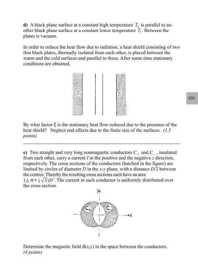
d) A black plane surface at a constant high temperature Th is parallel to an-other black plane surface at a constant lower temperature Tl . Between theplates is vacuum.
In order to reduce the heat flow due to radiation, a heat shield consisting of twothin black plates, thermally isolated from each other, is placed between thewarm and the cold surfaces and parallel to these. After some time stationaryconditions are obtained.
By what factor ξ is the stationary heat flow reduced due to the presence of theheat shield? Neglect end effects due to the finite size of the surfaces. (1.5points)___________________________________________________________________________
e) Two straight and very long nonmagnetic conductors C + and C − , insulatedfrom each other, carry a current I in the positive and the negative z direction,respectively. The cross sections of the conductors (hatched in the figure) arelimited by circles of diameter D in the x-y plane, with a distance D/2 betweenthe centres. Thereby the resulting cross sections each have an area( )1
1218π + 3 D2.The current in each conductor is uniformly distributed over
the cross section.
Determine the magnetic field B(x,y) in the space between the conductors.(4 points)
102
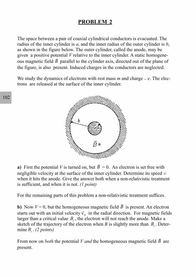
PROBLEM 2
The space between a pair of coaxial cylindrical conductors is evacuated. Theradius of the inner cylinder is a, and the inner radius of the outer cylinder is b,as shown in the figure below. The outer cylinder, called the anode, may begiven a positive potential V relative to the inner cylinder. A static homogene-ous magnetic field
rB parallel to the cylinder axis, directed out of the plane of
the figure, is also present. Induced charges in the conductors are neglected.
We study the dynamics of electrons with rest mass m and charge _ e. The elec-trons are released at the surface of the inner cylinder.
a) First the potential V is turned on, but rB = 0. An electron is set free with
negligible velocity at the surface of the inner cylinder. Determine its speed vwhen it hits the anode. Give the answer both when a non-relativistic treatmentis sufficient, and when it is not. (1 point)
For the remaining parts of this problem a non-relativistic treatment suffices.
b) Now V = 0, but the homogeneous magnetic field rB is present. An electron
starts out with an initial velocity rv 0 in the radial direction. For magnetic fields
larger than a critical value Bc , the electron will not reach the anode. Make asketch of the trajectory of the electron when B is slightly more than Bc . Deter-mine Bc . (2 points)
From now on both the potential V and the homogeneous magnetic field rB are
present.

103
c) The magnetic field will give the electron a non-zero angular momentum Lwith respect to the cylinder axis. Write down an equation for the rate of changedL/dt of the angular momentum. Show that this equation implies that
L keBr− 2
is constant during the motion, where k is a definite pure number. Here r is thedistance from the cylinder axis. Determine the value of k. (3 points)
d) Consider an electron, released from the inner cylinder with negligible ve-locity, that does not reach the anode, but has a maximal distance from the cyl-inder axis equal to rm . Determine the speed v at the point where the radial dis-tance is maximal, in terms of rm . (1 point)
e) We are interested in using the magnetic field to regulate the electron currentto the anode. For B larger than a critical magnetic field Bc , an electron, re-leased with negligible velocity, will not reach the anode. Determine Bc .(1 point)
f) If the electrons are set free by heating the inner cylinder an electron will ingeneral have an initial nonzero velocity at the surface of the inner cylinder. Thecomponent of the initial velocity parallel to
rB is v B , the components
orthogonal to rB are vr (in the radial direction) and vϕ (in the azimuthal direc-
tion, i.e. orthogonal to the radial direction).
Determine for this situation the critical magnetic field Bc for reaching the an-ode. (2 points)

104
PROBLEM 3
In this problem we consider some gross features of the magnitude of mid-oceantides on earth. We simplify the problem by making the following assumptions:
(i) The earth and the moon are considered to be an isolated system, (ii) the distance between the moon and the earth is assumed to be constant, (iii) the earth is assumed to be completely covered by an ocean, (iv) the dynamic effects of the rotation of the earth around its axis are
neglected, and (v) the gravitational attraction of the earth can be determined as if all mass
were concentrated at the centre of the earth.
The following data are given:Mass of the earth: M = 5.98 . 1024 kgMass of the moon: Mm = 7.3 . 1022 kgRadius of the earth: R = 6.37 . 106 mDistance between centre of the earth and centre of the moon:L = 3.84 . 108 mThe gravitational constant: G = 6.67 . 10 -11 m3 kg-1 s-2.
a) The moon and the earth rotate with angular velocity ω about their commoncentre of mass, C. How far is C from the centre of the earth? (Denote this dis-tance by l.)
Determine the numerical value of ω. (2 points)
We now use a frame of reference that is co-rotating with the moon and thecenter of the earth around C. In this frame of reference the shape of the liquidsurface of the earth is static.

105
In the plane P through C and orthogonal to the axis of rotation the position of apoint mass on the liquid surface of the earth can be described by polar coordi-nates r, ϕ as shown in the figure. Here r is the distance from the centre of theearth.
We will study the shaper (ϕ) = R + h (ϕ)
of the liquid surface of the earth in the plane P.
b) Consider a mass point (mass m) on the liquid surface of the earth (in theplane P). In our frame of reference it is acted upon by a centrifugal force andby gravitational forces from the moon and the earth. Write down an expressionfor the potential energy corresponding to these three forces.
Note: Any force F(r), radially directed with respect to some origin, is the nega-tive derivative of a spherically symmetric potential energy V(r):F r V r( ) ( ).= − ′ (3 points)
c) Find, in terms of the given quantities M, Mm , etc, the approximate form h(ϕ) ofthe tidal bulge. What is the difference in meters between high tide and low tide in thismodel?
You may use the approximate expression
valid for a much less than unity.
In this analysis make simplifying approximations whenever they are reasonable. (5points)
11 2
1 3 12
12
2 2
+ −≈ + + −
a aa a
coscos ( cos ),

106
27th INTERNATIONAL PHYSICS OLYMPIADOSLO, NORWAY
THEORETICAL COMPETITIONJULY 2 1996
Solution Problem 1
a) The system of resistances can be redrawn as shown in the figure:
The equivalent drawing of the circuit shows that the resistance between point cand point A is 0.5Ω, and the same between point d and point B. The resistancebetween points A and B thus consists of two connections in parallel: the direct1Ω connection and a connection consisting of two 0.5Ω resistances in series,in other words two parallel 1Ω connections. This yields
R = 0.5 Ω .
107
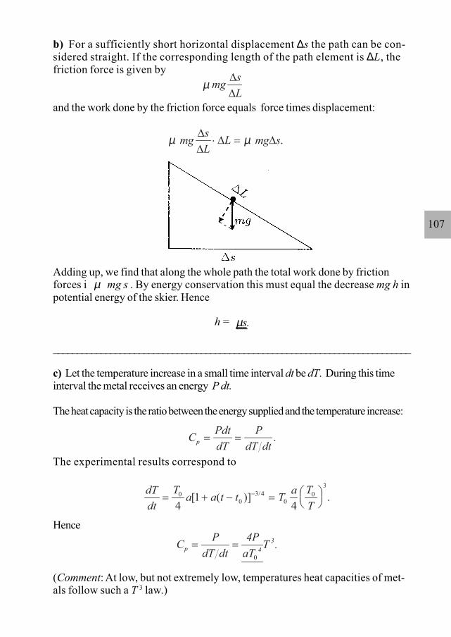
b) For a sufficiently short horizontal displacement ∆s the path can be con-sidered straight. If the corresponding length of the path element is ∆L, thefriction force is given by
and the work done by the friction force equals force times displacement:
Adding up, we find that along the whole path the total work done by frictionforces i µ mg s . By energy conservation this must equal the decrease mg h inpotential energy of the skier. Hence
h = µs.
___________________________________________________________________________
c) Let the temperature increase in a small time interval dt be dT. During this timeinterval the metal receives an energy P dt.
The heat capacity is the ratio between the energy supplied and the temperature increase:
The experimental results correspond to
Hence
(Comment: At low, but not extremely low, temperatures heat capacities of met-als follow such a T 3 law.)
dTdt
T a a t t T a TT
= + − =
−00
3 40
03
41
4[ ( )] ./
C PdtdT
P .p = =dT dt
C P 4PaT
T .p 43= =
dT dt 0
µ mg sL
∆∆
µ µmg sL
L mg s∆∆
∆ ∆⋅ = .

108
d)
Under stationary conditions the net heat flow is the same everywhere:
Adding these three equations we get
where J0 is the heat flow in the absence of the heat shield. Thus ξ = J/J0 takes thevalue
ξ = 1/3.
___________________________________________________________________________
e) The magnetic field can be determined as the superposition of the fields oftwo cylindrical conductors, since the effects of the currents in the area of inter-section cancel. Each of the cylindrical conductors must carry a larger currentI′, determined so that the fraction I of it is carried by the actual cross section(the moon-shaped area). The ratio between the currents I and I′ equals the ratiobetween the cross section areas:
Inside one cylindrical conductor carrying a current I′ Ampère’s law yields at adistance r from the axis an azimuthal field
J T Th= −σ ( )414
J T T= −σ ( )14
24
J T Tl= −σ ( )24 4
3 4 40J T T Jh l= − =σ ( ) ,
II
DD′
=+
=+( ) .
π
π
π123
82
42
2 3 36π
Br
I rD
I rDφ π
µπ
µπ
=′π
=′0
2
42
022
2 .

109
The cartesian components of this are
For the superposed fields, the currents are I′ and the corresponding cylinderaxes are located at x = m D/4.
The two x-components add up to zero, while the y-components yield
i.e., a constant field. The direction is along the positive y-axis.
Solution Problem 2
a) The potential energy gain eV is converted into kinetic energy. Thus
(non-relativistically)
(relativistically).
Hence
(1)
b) When V = 0 the electron moves in a homogeneous static magnetic field. Themagnetic Lorentz force acts orthogonal to the velocity and the electron will move in acircle. The initial velocity is tangential to the circle.
The radius R of the orbit (the “cyclotron radius”) is determined by equating thecentripetal force and the Lorentz force:
B B yr
I yDx = − = −
′φ
µπ
2 02 ; B B x
rI x
Dy = =′
φµ2 0
2 .π
BD
I x D I x D ID
IDy = ′ + − ′ − =
′=
+2 4 4 6
2 3 302
0 0µπ
[ ( / ) ( / )]( )
,µ µππ
12 m eVv 2 =
mc1
mc eV2
2
−− =
v 2 2c
v =−
+
2eV m
c 1 mcmc eV
2
22
(non - relativistically)
( ) (relativistically).
m

110
i.e.
(2)
From the figure we see that in the critical case the radius R of the circle satisfies
By squaring we obtain ,
i.e. .
Insertion of this value for the radius into the expression (2) gives the critical field
c) The change in angular momentum with time is produced by a torque. Herethe azimuthal component Fφ of the Lorentz force provides atorque Fφ r. It is only the radial component vr = dr/dt of the velocity that pro-vides an azimuthal Lorentz force. Hence
which can be rewritten as
dLdt
eBr drdt
= ,
ddt
L eBr( ) .− =2
20
R b a / 2b2 2= −( )
B meR
2bmb a ec
0 02 2= =
−v v
( ).
a R b 2bR R2 2 2 2+ = − +
mR
02v
eBv =0 ,
meR
0vB = .
a R2 2+ = b - R
F e B→ →
= − ×( ) rv

111
Hence (3)
is constant during the motion. The dimensionless number k in the problem text isthus k = 1/2.
d) We evaluate the constant C, equation (3), at the surface of the inner cylinderand at the maximal distance rm :
which gives
(4)
Alternative solution: One may first determine the electric potential V(r) asfunction of the radial distance. In cylindrical geometry the field falls off inverselyproportional to r, which requires a logarithmic potential, V(s) = c1 ln r + c2.When the two constants are determined to yield V(a) = 0 and V(b) = V we have
The gain in potential energy, sV(rm), is converted into kinetic energy:
Thus
(5)
(4) and (5) seem to be different answers. This is only apparent since rm is not an in-dependent parameter, but determined by B and V so that the two answers areidentical.
e) For the critical magnetic field the maximal distance rm equals b, the radius of theouter cylinder, and the speed at the turning point is then
C L eBr= − 12
2
0 12
2 12
2− = −eBa mvr eBrm m
veB r a
mrm
m
=−( ) .
2 2
2
V r V r ab a
( ) ln( / )ln( / )
.=
12
2mv eVr ab am=
ln( / )ln( / )
.
veVm
r ab am=
2 ln( / )ln( / )
.
veB b a
mb=
−( ) .2 2
2
112
Since the Lorentz force does no work, the corresponding kinetic energyequals eV (question a):
.
The last two equations are consistent when
The critical magnetic field for current cut-off is therefore
f) The Lorentz force has no component parallel to the magnetic field, and conse-quently the velocity component vB is constant under the motion. The correspondingdisplacement parallel to the cylinder axis has no relevance for the question of reach-ing the anode.
Let v denote the final azimuthal speed of an electron that barely reaches the anode.Conservation of energy implies that
giving (6)
Evaluating the constant C in (3) at both cylinder surfaces for the critical situation wehave
Insertion of the value (6) for the velocity v yields the critical field
v v v eV mr= + +2 2 2 / .φ
12
2 2 12
2m v v v m v vr( ) ( ),B2
B2eV =+ + + +φ
mv a eB a mvb eB bc c− = −12
2 12
2.φ
[ ]Bm vb v ae b a
mbe b a
v v eV m v a bc r=−
−=
−+ + −
2 2 22 2 2 22 2( )
( ) ( )/ / .φ
φ φ
12
2mv
B bb a
mVec =
−2 2
2 2 .
eB b amb
e V m( ) .2 2
22−
=
v eV m= 2

113
Solution Problem 3
a) With the centre of the earth as origin, let the centre of mass C be locatedat . The distance l is determined by
M l = Mm (L - l),which gives
(1)
less than R, and thus inside the earth.
The centrifugal force must balance the gravitational attraction between the moonand the earth:
which gives
(2)
(This corresponds to a period 2π/ω = 27.2 days.) We have used (1) to elimi-nate l.
b) The potential energy of the mass point m consists of three contributions:
(1) Potential energy because of rotation (in the rotating frame of reference, seethe problem text),
where is the distance from C. This corresponds to the centrifugal forcemω 2r1, directed outwards from C.
(2) Gravitational attraction to the earth,
(3) Gravitational attraction to the moon,
l→
rr1
−G mMr
.
l MM M
Lm
m
=+
= ⋅4 63 106. ,m
M l G MML
mω22= ,
ω = =+
= ⋅ − −GML l
G M ML
m m2 3
6 12 67 10( ) . .s
−12
212m rω ,

114
where is the distance from the moon.
Describing the position of m by polar coordinates r, φ in the plane orthogonal to theaxis of rotation (see figure), we have
Adding the three potential energy contributions, we obtain
(3)
Here l is given by (1) and
c) Since the ratio r/L = a is very small, we may use the expansion
Insertion into the expression (3) for the potential energy gives
(4)
apart from a constant. We have used that
when the value of ω2 , equation (2), is inserted.
− G mMr
m
mr ,
rrm
r r rr (r l ) r 2rl l2 2 21
2 = − = − +cosφ .
V( r) m (r 2rl l ) G mMr
G mMr
.2 2 2 m
m
rr= − − + − −
12
cosω φ
r r r rrr (L r) L 2Lr r L 1 ( r L ) 2( r L ) .m2 2 2 2= − = − + = + − cosφ
11 2
1 3 12
2 12
2
+ −= + + −
a aa a
coscos ( cos ).
φφ φ
V r m r GMr
GM rLm( , ) ( cos ),φ ω φ= − − − −1
22 2
2
32
23 1
m rl GmM rLmω φ φ2
2 0cos cos ,− =

115
The form of the liquid surface is such that a mass point has the same energy V every-where on the surface. (This is equivalent to requiring no net force tangential to thesurface.) Putting
r = R + h,
where the tide h is much smaller than R, we have approximately
as well as
Inserting this, and the value (2) of ω into (4), we have
(5)
again apart from a constant.
The magnitude of the first term on the right-hand side of (5) is a factor
smaller than the second term, thus negligible. If the remaining two terms in equation(5) compensate each other, i.e.,
then the mass point m has the same energy everywhere on the surface. Here r2 cansafely be approximated by R2 , giving the tidal bulge
The largest value occurs for φ = 0 or π, in the direction ofthe moon or in the opposite direction, while the smallest value
1 1 1 11
1 1 12r R h R h R R
hR R
hR
=+
= ⋅+
≅ − = −( )
( ) ,
r R Rh h R Rh2 2 2 22 2= + + ≅ + .
V r m G M M RL
h GMR
h GM rL
m m( , ) ( ) ( cos ),φ φ= −+
+ − −3 2
2
32
23 1
( )M MM
RL
m+
≅ −3
510
h M r RML
m= −2 2
32
23 1( cos ),φ
h M RMLm= −
4
32
23 1( cos ).φ
h M R MLmmax = 4 3

116
corresponds to φ = π/2 or 3π/2.
The difference between high tide and low tide is therefore
(The values for high and low tide are determined up to an additive constant, but thedifference is of course independent of this.)
Here we see the Exam Officer, Michael Peachey (in the middle), with his helperRod Jory (at the left), both from Australia, as well as the Chief examiner, Per
Chr. Hemmer. The picture was taken in a silent moment during the theoryexamination. Michael and Rod had a lot of experience from the 1995 IPhO in
Canberra, so their help was very effective and highly appreciated!
Phot
o: A
rnt
Inge
Vis
tnes
h h M RML
mmax min . .− = =
32
0 544
3 m
h M R MLmmin = − 4 32