part - 3 road & bridge
TRANSCRIPT

GOVERNMENT OF MADHYA PRADESH, URBAN ADMINISTRATION AND DEVELOPMENT DEPARTMENT
SPECIFICATIONS (4 PARTS)
PART - 3
ROAD & BRIDGE
ISSUED BY
COMMISSIONER Urban Administration and Development Department
Government of Madhya Pradesh, Bhopal

INDEX
S.No. Description Page No.1. General 1 - 27
2. Site Clearance 28-33
3. Earth Work 34 - 59
4. Granular Sub Base 60 - 85
5. Base And Surface Courses 86 - 161
6. Concrete Pavement 162 - 190
7. Geosynthetics And Reinforced Earth 191 - 207
8. Traffic Signs 208 - 229
9. Quality Control For Road Works 230 – 239
10. Materials For Structures 240 – 250
11. Pile Foundations 251 – 262
12. Well Foundations 263 – 275
13 Brick Masonry 276 – 283
14. Stone Masonry 284 – 291
15. Form Work 292 – 297
16. Steel Reinforcement (Untensioned) 298 – 303
17. Structural Concrete 304 – 317
18. Prestressing 318 – 328
19. Structural Steel 329 - 351
20. Bearings 352 – 371
21 Open Foundations 372 - 376
22 Sub-Structure 377 – 380
23 Concrete Superstructure 381 – 385
24 Surface And Sub-Surface Geotechnical Exploration 386 – 398
25 River Training Work And Protection Work 399 – 406
26 Expansion Joints 407 – 422
27 Wearing Coat And Appurtenances 423 – 428
28 Repair Of Structures 429 – 441
29 Pipe Culverts 442 – 446
30. Maintenance Of Road 447 - 452

SECTION 100

CONTENT
Clause No Description101 INTRODUCTION102 DEFINITIONS103 MATERIALS AND TEST STANDARDS104 SIEVE DESIGNATIONS105 SCOPE OF WORK106 CONSTRUCTION EQUIPMENT107 CONTRACT DRAWINGS108 SITE INFORMATION109 SETTING OUT110 PUBLIC UTILITIES111 PRECAUTIONS FOR SAFEGUARDING THE ENVIRONMENT112 ARRANGEMENT FOR TRAFFIC DURING CONSTRUCTION113 GENERAL RULES FOR THE MEASUREMENT OF WORKS FOR
PAYMENT114 SCOPE OF RATES FOR DIFFERENT ITEMS OF WORK115 METHODOLOGY AND SEQUENCE OF WORK116 CRUSHED STONE AGGREGATES117 APPROVAL OF MATERIALS118 SUPPLY OF QUARRY SAMPLES119 USE OF SURFACES BY CONSTRUCTION TRAFFIC120 FIELD LABORATORY121 SUPPLY OF PROJECT RECORD
101 INTRODUCTIONThese specifications shall apply to all such road and bridge works as are required to be executed under theContract or otherwise directed by the Engineer-in-Charge (hereinafter referred to as the Engineer). Inevery case, the work shall be carried out to the satisfaction of the Engineer and conform to the location,lines, dimensions, grades and cross-sections shown on the drawings or as indicated by the Engineer. Thequality of materials, processing of materials as may be needed at the site, salient features of theconstruction work and quality of finished work, measures for safety of workers and public and trafficarrangements during execution shall comply with the requirements set forth in succeeding sections. Wherethe drawings and Specifications describe a portion of the work in only general terms, and not in completedetail, it shall be understood that only the sound engineering practice is to prevail, materials andworkmanship of the best quality are to be employed and the instructions of the Engineer are to be fullycomplied with.
A list of Indian Roads Congress Specifications and Recommended Codes of Practice which have beenmade use of in the preparation of these Specifications is given at Appendix-1. The latest edition of allSpecifications/Standards till 30 (thirty) days before the final date of submission of the tender, shall beadopted.
102 DEFINITIONSThe words like Contract, Contractor, Engineer (synonymous with Engineer -in-Charge), Drawings,Employer, Government, Works and Work Site used in these Specifications shall be considered to have themeaning as understood from the definitions of these terms given in the General Conditions of Contract.
AASHTO : American Association of State Highway andTransportation Officials
ASTM : American Society for Testing and MaterialsBS : British Standard published by the British Standards
InstitutionBIS : Bureau of Indian StandardsBOQ : Bill of QuantitiesCBR : California Bearing RatioIRC : Indian Roads CongressIS : Indian Standard published by the Bureau of Indian
StandardsQA : Quality Assurance
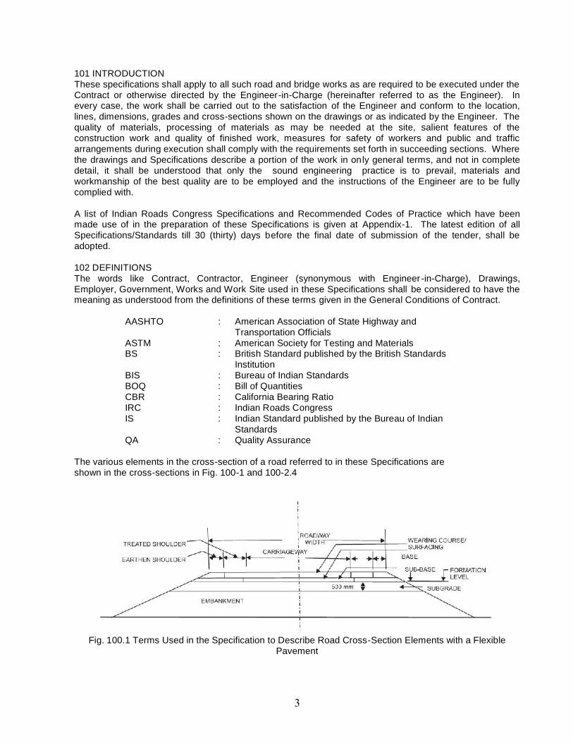
The various elements in the cross-section of a road referred to in these Specifications areshown in the cross-sections in Fig. 100-1 and 100-2.4
Fig. 100.1 Terms Used in the Specification to Describe Road Cross-Section Elements with a FlexiblePavement
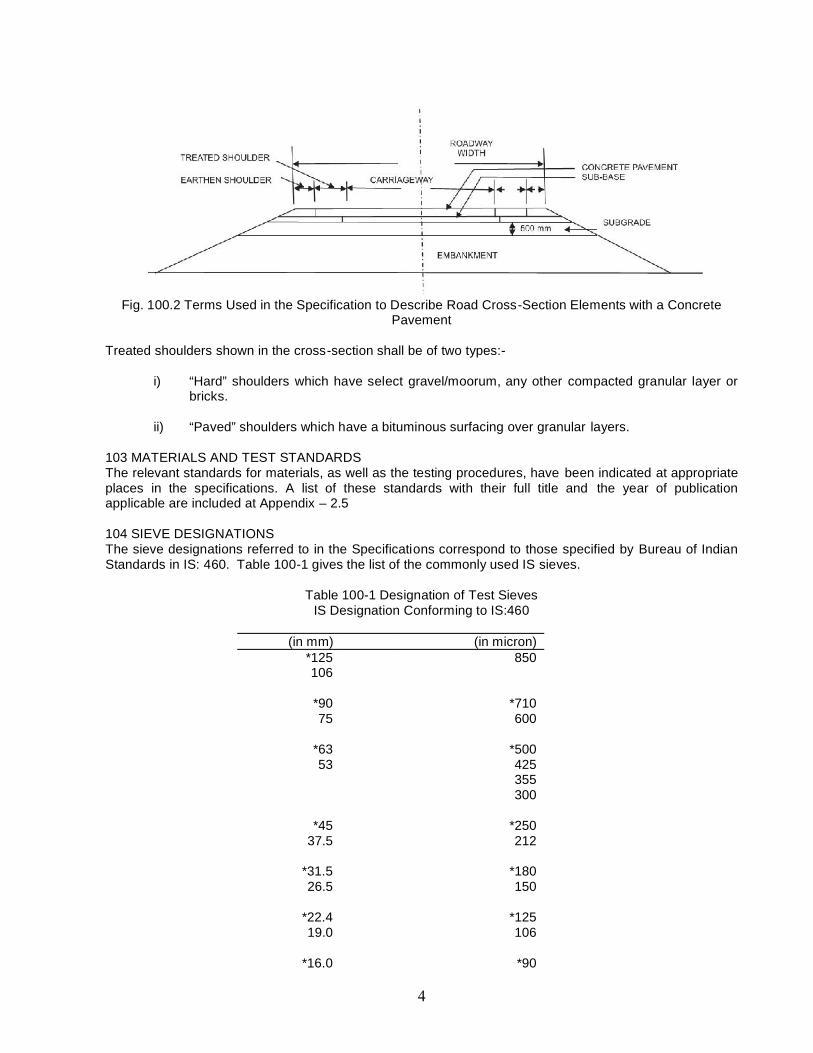
Fig. 100.2 Terms Used in the Specification to Describe Road Cross-Section Elements with a ConcretePavement
Treated shoulders shown in the cross-section shall be of two types:-
i) “Hard” shoulders which have select gravel/moorum, any other compacted granular layer orbricks.
ii) “Paved” shoulders which have a bituminous surfacing over granular layers.
103 MATERIALS AND TEST STANDARDSThe relevant standards for materials, as well as the testing procedures, have been indicated at appropriateplaces in the specifications. A list of these standards with their full title and the year of publicationapplicable are included at Appendix – 2.5
104 SIEVE DESIGNATIONSThe sieve designations referred to in the Specifications correspond to those specified by Bureau of IndianStandards in IS: 460. Table 100-1 gives the list of the commonly used IS sieves.
Table 100-1 Designation of Test SievesIS Designation Conforming to IS:460
(in mm) (in micron)*125 850106
*90 *71075 600
*63 *50053 425
355300
*45 *25037.5 212
*31.5 *18026.5 150
*22.4 *12519.0 106
*16.0 *90
13.2 74
*11.2 *639.50 53
*8.00 *456.70
*5.604.75
*4.003.35
*2.802.36
*2.001.70
*1.401.18
*1.00
Notes:1) ‘*’ are the principal sizes stated in ISO-5652) Sieve sizes given in BS:410 & ASTM–E 11 are same as in IS:4603) Only sieves with square openings shall be used.
105 SCOPE OF WORK105.1 The work to be carried out under the Contract shall consist of the various items as generallydescribed in the Tender Documents as well as in the Bill of Quantities furnished in the Tender Documents.
105.2 The works to be performed shall also include all general works preparatory to the construction ofroads, drainage and all other related works. The works shall include work of any kind necessary for the dueand satisfactory construction, completion and maintenance of works to the intent and meaning of thedrawings and these Specifications and further drawings and orders that may be issued by the Engineerfrom time to time. The scope of work shall include compliance by the Contractor with all Conditions ofContract, whether specifically mentioned or not in the various Sections of these Specifications, allmaterials, apparatus, plant, equipment, tools, fuel, water, strutting, timbering, transport, offices, stores,workshop, staff, labour and the provision of proper and sufficient protective works, diversions, temporaryfencing and lighting. It shall also include, safety of public workers, first-aid equipment, suitableaccommodation for the staff and workmen with adequate sanitary arrangements, the effecting andmaintenance of all insurances, the payment of all wages, salaries, fees, royalties, duties or other chargesarising out of the erection of works and the regular clearance of rubbish, reinstatement and clearing-up ofthe site as may be required on completion of works, safety of the public and protection of the works andadjoining land.
105.3 The Contractor shall ensure that all actions are taken to build in quality assurance in the planning,management and execution of works. The quality assurance shall cover all states of work such as settingout, selection of materials, selection of construction methods, selection of equipment and plant, deploymentof personnel and supervisory staff, quality control testing, etc. The QA programme shall cover the details asper IRC:SP:47 and IRC:SP:57. These shall broadly cover quality assurance aspects of all servicesrendered, all items to be supplied and all activities to be performed under the contract including temporarystructures and equipments which will influence the quality of the completed works or the progress of thecontract.

As a minimum, it shall cover the following :i) Organisation and management responsibility,ii) Document and data control,iii) Construction programme,iv) Methods statements,v) Process control,vi) Working, inspection, testing and documentary procedures,vii) Arrangement for traffic during construction and maintenance,viii) Control and documentation of purchasing and handling of materials,ix) Non-conformity and corrective actions,x) Internal quality audit,xi) Servicing,xii) Training of staff,xiii) Site environmental plan
The general procedures of the QA programme shall be submitted to the Engineer for approval, not laterthan 28 days after the date of letter of acceptance. The specia l part of the QA programme shall besubmitted successively to the effect that it shall have been approved prior to the commencement of theactivities to which the programme shall apply. The work of building in quality assurance shall be deemed tobe covered in the scope of the work.
105.4 The Contractor shall furnish, at least 7 days in advance unless otherwise stipulated in the contracthis programme of commencement of item of work, the method of working he intends to adopt for variousitems of work such as site clearance, construction for embankment, sub-base, base, surfacing, culverts,bridges, retaining walls, well-sinking, cast-in-situ piling, construction of cast-in-situ pre-stressed concretesuperstructure, and such other items for which the Engineer demands the submission of the method ofworking. He shall provide information regarding the details of the method of working and equipment heproposes to employ and satisfy the Engineer about the adequacy and safety of the same. The soleresponsibility for the safety and adequacy of the methods adopted by the Contractor will, however, rest onthe Contractor, irrespective of any approval given by the Engineer.
106. CONSTRUCTION EQUIPMENTIn addition to the conditions indicated in the Contract Documents, the following conditions regarding use ofequipment in works shall be satisfied:
a) The Contractor shall be required to give a trial run of the equipment for establishing theircapability to achieve the laid down Specifications and tolerances to the satisfaction of theEngineer before commencement of the work;
b) All equipment provided shall be of proven efficiency and shall be operated and maintained atall times in a manner acceptable to the Engineer;
c) Plants, equipments and instruments provided shall have adequate sensitivity, facility forcalibration to desired level and shall be robust; d) Plants, equipments and instrumentsprovided shall have data logging arrangement and control systems to enable automaticfeedback control of process;
e) Plants, equipments and instruments provided shall have adequate safety features andpollution control devices;
f) Plants equipments and instruments provided shall be operated by skilled and qualifiedoperators;
g) All the plant/equipment to be deployed on the works shall be got approved from the Engineerfor ensuring their fitness and efficiency before commencement of work;
h) Any material or equipment not meeting the approval of the Engineer shall be removed fromthe site forthwith;
i) No equipment shall be removed from site without permission of the Engineer;j) The Contractor shall also make available stand by equipments and spare parts; andk) The Contractor shall also make available equipments for site quality control work as directed
by the Engineer.

107 CONTRACT DRAWINGS107.1 The Contract Drawings provided for tendering purposes shall be as contained in the TenderDocuments and shall be used as reference only. The Contractor should visualize the nature and type ofwork contemplated and to ensure that the rates and prices quoted by him in the Bill of Quantities have dueconsideration of the site and complexities of work involved during actual execution/construction.
107.2 The Contractor based on hs surveys and investigations, shall submit the working drawings (hard/softcopy) to the Engineer for each activity atleast 45 days in advance of the scheduled date to the start of theactivity as per his aproved work programme. The working drawings shall clearly show the modifications, ifany, proposed with reference to corresponding tender drawings. The Engineer shall review the workingdrawings including the modifications proposed, if any, revise the drawings, if required, approve and issue tothe Contractor two copies of Good for Construction (GFC) drawings atleast 21 days in advance of thescheduled date of the start of the activity.
107.3 After careful study of GFC drawings, the Contractor shall prepare all supplementary and workingdrawings and shall submit the same to the Engineer for approval 7 days prior to schedule date forexecution of the works unless otherwise stipulated in the Contract.
107.4 Examination and/or approval by the Engineer of any drawings or other documents submitted by theContractor shall not relieve the Contractor of his responsibilities or liabilities under the Contract.
107.5 The tendered rates/prices for the work shall be deemed to include the cost of preparation, supply anddelivery of all necessary drawings, prints, tracings and negatives which the Contractor is required toprovide in accordance with the Contract.
108 SITE INFORMATION108.1 The information about the site of work and site conditions in the Tender Documents is given in goodfaith for guidance only but the Contractor shall satisfy himself regarding all aspects of site conditions.
108.2 The location of the works and the general site particulars are as shown in the Site plan/Index planenclosed with the Tender Documents.
108.3 Whereas the right-of-way to the bridge sites/road works shall be provided to the Contractor by theEngineer, the Contractor shall have to make his own arrangement for the land required by him for siteoffices, field laboratory, site for plants and equipments, labour camps, stores, etc.10
109. SETTING OUT109.1 The Contractor shall establish working Bench Marks tied with the Reference Bench Mark in the areasoon after taking possession of the site. The Reference Bench Mark for the area shall be as indicated inthe Contract Documents and the values of the same shall be obtained by the Contractor from the Engineer.The working Bench Marks shall be at the rate of four per km and also at or near all drainage structures,over-bridges and underpasses. The working Bench Marks/levels should be got approved from theEngineer. Checks must be made on these Bench Marks once every month and adjustments, if any, gotagreed with the Engineer and recorded. An up-to-date record of all Bench Marks including approvedadjustments, if any, shall be maintained by the Contractor and also a copy supplied to the Engineer for hisrecord.
109.2 The lines and levels of formation, side slopes, drainage works, carriageways and shoulders shall becarefully set out and frequently checked, care being taken to ensure that correct gradients and cross-sections are obtained everywhere.
109.3 In order to facilitate the setting out of the works, the center line of the carriageway or highway mustbe accurately established by the Contractor and approved by the Engineer. It must then be accuratelyreferenced in a manner satisfactory to the Engineer, every 50 m intervals in plain and rolling terrains and20 m intervals in hilly terrain and in all curve points as directed by the Engineer, with marker pegs andchainage boards set in or near the fence line, and a schedule of reference dimensions shall be prepared
and supplied by the Contractor to the Engineer. These markers shall be maintained until the works reachfinished formation level and are accepted by the Engineer.
109.4 On construction reaching the formation level stage, the center line shall again be set out by theContractor and when approved by the Engineer, shall be accurately referenced in a manner satisfactory tothe Engineer by marker pegs set at the outer limits of the formation.
109.5 No reference peg or marker shall be moved or withdrawn without the approval of the Engineer andno earthwork or structural work shall be commenced until the center line has been referenced.
109.6 The Contractor will be the sole responsible party for safe-guarding all survey monuments, benchmarks, beacons, etc. The Engineer will provide the Contractor with the data necessary for setting out thecenter line. All dimensions and levels shown on the drawings or mentioned in documents forming part of orissued under the Contract shall be verified by the Contractor on the site and he shall immediately informthe Engineer of any apparent errors or discrepancies in such dimensions of levels. The Contractor shall, inconnection with the staking out of the center line, survey the terrain along the road and shall submit to theEngineer for his approval, a profile along the road center line and cross -sections at intervals as required bythe Engineer.
109.7 After obtaining approval of the Engineer, work on earthwork can commence and the profile andcross-sections as per Section 305, shall form the basis for measurements and payment. The Contractorshall be responsible for ensuring that all the basic traverse points are in place at the commencement of thecontract and, if any, are missing, or appear to have been disturbed, the Contractor shall makearrangements to re-establish these points. A “Survey File” containing the necessary data will be madeavailable for this purpose. If in the opinion of the Engineer, design modifications of the center line or gradeare advisable, the Engineer will issue detailed instructions to the Contractor and the Contractor shallperform the modifications in the field, as required, and modify the ground levels on the cross-sectionsaccordingly as many times as required. There will be no separate payment for any survey work performedby the Contractor. The cost of these services shall be considered as being included in the rate of the itemsof work in the Bill of Quantities.
109.8 The work of setting out shall be deemed to be a part of general works preparatory to the execution ofwork and no separate payment shall be made for the same.
109.9 Precision automatic levels, having a standard deviation of +2 mm per km, and fitted with micrometerattachment shall be used for all double run levelling work. Setting out of the road alignment andmeasurement of angles shall be done by using theodolite with traversing target, having an accuracy of onesecond. Measurement of distances shall be done preferably using precision instruments like Distomat.
110 PUBLIC UTILITIES110.1 Drawings scheduling the affected services like water pipes, sewers, oil pipelines, cables, gas ductsetc. owned by various authorities including Public Undertakings and Local Authorities included in theContract Documents shall be verified by the Contractor for the accuracy of the information prior to thecommencement of any work.
110.2 Notwithstanding the fact that the information on affected services may not be exhaustive, the finalposition of these services within the works shall be supposed to have been indicated based on theinformation furnished by different bodies and to the extent the bodies are familiar with the final proposals.The intermediate stages of the works are, however, unknown at the design stage, these being dictated bythe Contractor’s methods of working. Accordingly, the Contractor’s programme must take into account theperiod of notice and duration of diversionary works of each body as given on the Drawings and theContractor must also allow for any effect of these services and alterations upon the Works and forarranging regular meetings with the various bodies at the commencement of the Contract and throughoutthe period of the Works, the Contractor shall have no objection if the public utility bodies vary theirdecisions in the execution of their proposals in terms of programme and construction, provided that, in theopinion of the Engineer, the Contractor has received reasonable notice thereof before the relevantalterations are put in hand.

110.3 No clearance or alterations to the utility shall be carried out unless specially ordered by the Engineer.
110.4 Any services affected by the Works must be temporarily supported by the Contractor who must alsotake all measures reasonably required by the various bodies to protect their services and property duringthe progress of the Works.
110.5 The Contractor may be required to carry out certain works for and on behalf of the various bodiesand he shall also provide, with the prior approval of the Engineer, such assistance to the various bodies asmay be authorized by the Engineer.
110.6 The work of temporarily supporting and protecting the public utility services during execution of theWorks shall be deemed to be part of the Contract and not extra payment shall be made for the same.
110.7 The Contractor shall be responsible to co-ordinate with the service providers for cutting of trees,shifting of utilities, removal of encroachments etc. to make site unencumbered for completion of work. Thiswill include frequent follow-up meetings. Co-ordination for making project site unencumbered shall bedeemed to be part of the Contract and no extra payment shall be made for the same.
110.8 In some cases, the Contractor may be required to carry out the removal or shifting of certainservices/utilities on specific orders from the Engineer for which payment shall be made to him. Suchworks, however, shall be taken up by the Contractor only after obtaining clearance from the Engineer andensuring adequate safety measures.
111 PRECAUTIONS FOR SAFEGUARDING THE ENVIRONMENT111.1 GeneralThe Contractor shall take all precautions for safeguarding the environment during the course of theconstruction of the works. He shall abide by all laws, rules and regulations in force governing pollution andenvironmental protection that are applicable in the area where the works are situated.
111.2 Borrow pits for Embankment ConstructionBorrow pits shall not be dug in the right-of-way of the road. The stipulations in Section 305.2.2 andguidelines provided in IRC 10 shall govern. The Contractor shall seek prior approval from the concernedauthorities for operating the borrow pits.
111.3 Quarry OperationsThe Contractor shall obtain materials from quarries only after obtaining the consent of the MiningDepartment or other concerned authorities. The quarry operations shall be undertaken within the purviewof the rules and regulations in force.
111.4 Control of Soil Erosion, Sedimentation and Water PollutionThe Contractor shall carry out the works in such a manner that soil erosion is fully controlled, andsedimentation and pollution of natural water courses, ponds, tanks and reservoirs is avoided. Thestipulations in Clause 306 shall govern.
111.5 Pollution from Plants and Batching PlantsStone crushing and screening plants, Bituminous hot-mix plants, concrete batching plants etc. shall belocated sufficiently away from habitation, agricultural operations or industrial establishments. TheContractor shall take every precaution to reduce the levels of noise, vibration, dust and emissions from hisplants and shall be fully responsible for any claims or damages caused to the owners of property, fields andresidences in the vicinity and violation of pollution control norms, if any.
111.6 Substances Hazardous to HealthThe Contractor shall not use or generate any materials in the works which are hazardous to the health ofpersons, animals or vegetation. Where it is necessary to use some substances which can cause injury tothe health of workers, the Contractor shall provide protective clothing or appliances to his workers.

111.7 Use of Nuclear GaugesNuclear gauges shall be used only where permitted by the Engineer. The Contractor shall provide theEngineer with a copy of the regulations governing the safe use of nuclear gauges he intends to employ andshall abide by such regulations.
111.8 The Contractor must take all reasonable steps to minimize dust nuisance during the construction ofthe works along the haul roads and the worksites by sprinkling water at a frequency specified by theEngineer.
All existing highways and roads used by vehicles or equipments of the Contractor or any of his sub-contractors or suppliers of materials or plant, and similarly any new roads which are part of the works andwhich are being used by traffic, shall be kept clean and clear of all dust/mud or other extraneous materialsdropped by the said vehicles. Similarly, all dust/mud or other extraneous materials from the worksspreading on these highways shall be immediately cleared by the Contractor.
Clearance shall be effected immediately by sweeping and removal of debris, and all dust, mud and otherdebris shall be removed entirely from the road surface. Additionally, if so directed by the Engineer, theroad surface shall be hosed or watered using suitable equipment.
Any structural damage and loss of riding surface caused to the existing roads by the Contractor’sconstruction vehicles/ equipment shall be made good without any extra cost.
Compliance with the foregoing will not relieve the Contractor of any responsibility for complying with therequirements of any authority in respect of the roads used by him.
111.9 Occupational Health & Safety of the workforceThe Contractor shall prepare and submit to the Engineer the Occupational Health & Safety Procedures /Practices for the workforce in all quarry sites, plant sites, work sites, camp sites, etc., in accordance withthe applicable laws.
111.10 Water Sources and Water QualityThe Contractor shall provide independent sources of water supply, for use in the Works and for associatedstorage, workshop and work force compounds. Prior approval shall be obtained from the relevant StateAuthorities and all installations shall be in compliance with local regulations.
The Contractor shall protect all waterways, drains, lakes etc. and the like from pollution as a result of theexecution of the Works. All water and other liquid waste products arising on the Site shall be collected anddisposed of at a location on or off the Site and in a manner that shall not be cause either nuisance orpollution.
The Contractor shall at all times ensure that all existing stream courses and drains within and adjacent tothe Site are kept safe and free from any debris and any materials arising from the Works. The Contractorshall not discharge or deposit any matter arising from the execution of the Works into any water courseexcept with the permission of the Engineer and the regulatory authority concerned.
111.11 Air QualityThe Contractor shall device and implement methods of working to minimize dust, gaseous and other air-borne emissions and carry out the Works in such a manner as to minimize adverse impacts on the airquality.
The Contractor shall utilize effective water sprays during delivery, manufacture, processing and handling ofmaterials when dust is likely to be created, and to dampen stored materials during dry and windy weather.Stockpiles of friable materials shall be covered with clean tarpaulins, with applications of sprayed waterduring dry and windy weather. Stockpiles of materials or debris shall be dampened prior to their movement,except where this is contrary to the Specification.
Any vehicle with open load-carrying area used for transporting potentially dust-producing material shallhave properly fitting side and tail boards. Materials having the potential to produce dust shall not be loadedto a level higher than the side and tail boards and shall be covered with clean tarpaulins in good condition.The tarpaulin shall be properly secured and extend at least 300mm over the edges of the side and tailboards.
111.12 Construction CampsThe construction camps shall conform to the State and National building regulations as applicable. Thearea for the storage of polluted materials shall be stored on impervious floors and shall be surrounded byimpervious ditches in order to avoid spilling of polluted material to surrounding areas.
Construction camps shall be properly arranged to avoid noise pollution to the nearby habitants and to avoidcontamination of water courses from wastewater drainage. To prevent such contamination, wastewatergenerated at the campsites shall be discharged into soak pits. Human excreta shall be treated thoughseptic tanks prior to discharge and shall conform to directives and guidelines of the State. Wateraccumulated in tires, empty vessels and containers of all nature will be regularly cleaned to avoid therelated health hazards.
111.13 Control and Disposal of WastesThe Contractor shall control the disposal of all forms of waste generated by the construction operations andin all associated activities. No uncontrolled deposition or dumping shall be permitted. Wastes to be socontrolled shall include, but shall not be limited to, all forms of fuels and engine oils, all types of bitumen,cement, surplus aggregates, gravels, bituminous mixtures etc. The Contractor shall make specific provisionfor the proper disposal of these and any other waste products, conforming to local regulations andacceptable to the Engineer.
Spilling of oil and bituminous products during construction and transport shall be avoided to reduce thechances of contamination of surface as well as ground water.
111.14 Transport of Hazardous MaterialsTransport of al hazardous materials, in bulk or in sealed containers, shall meet the requirements of theState regulations. Prior to ordering transport of hazardous material in bulk, the Contractor must obtain theapproval of the relevant authority as well as of the Engineer. Precautionary measures and conformity withregulations shall be stated in a Method Statement for the approval of the Engineer. Sealed containers ofhazardous materials shall be stored in a well-ventilated room, well guarded and secured.
111.15 Emergency ResponseThe Contractor shall plan and provide remedial measures to be implemented in the event of occurrence ofemergencies such as spillages of oil or bitumen or chemicals. The Contactor shall provide the Engineerwith a statement of the measures he intends to implement in the event of such an emergency, which shallinclude a statement of how he intends to provide personnel adequately trained to implement suchmeasures.
111.16 Measurement for paymentThe compliance of all provisions made in this Clause 111 shall be deemed to be incidental to the work andno separate measurement shall be made. The Contractor shall be deemed to have made allowance forsuch compliance with these provisions in the preparation of his prices for items of work included in the Billof Quantities and full compensation for such compliance shall be deemed to be covered by those prices.”
112 ARRANGEMENT FOR TRAFFIC DURING CONSTRUCTION112.1 GeneralThe Contractor shall at all times, carry out work on the highway in a manner creating least interference tothe flow of traffic while consistent with the satisfactory execution of the same. For all works involvingimprovements to the existing highway, the Contractor shall, in accordance with the directives of theEngineer, provide and maintain, during execution of the work, a passage for traffic either along a part of theexisting carriageway under improvement or along a temporary diversion constructed close to the highway.Before taking up any construction or maintenance operation, the Contractor shall prepare a Traffic

Management Plan for each work zone and submit it to the Engineer for prior approval. This plan shouldinclude inter alia :
i) A qualified safety officer with support staff to serve as a site safety teamii) Provision of traffic safety devises as per IRC:SP 55 with the following specifications
a) Signages of retro-reflective sheet of high intensity gradeb) Delineators in the form of cones/drums made of plastic/rubber having retro-reflective red
and white bands, at a spacing of 5 m along with a reflective tape to be tied in betweenthe gaps of cones/drums. A bulb using solar energy is to be placed on the top of thecone/drum for delineation in the dark hours and night.
c) Barricades using iron sheet with adequate iron railing/frame painted with retro-reflectivepaint in the alternate yellow and black & white stripes. Warning lights at 5 m spacingshall be mounted on the barricades and kept lit in dark hours and night.
d) Road markings with hot applied thermoplastic paint with glass beads.iii) Safety measures for the workers engaged including personal protection equipmentiv) First aid and emergency response arrangementsv) Details and drawings of arrangements in compliance with other sub Sections of this Section.
112.2. Passage of Traffic along a Part of the Existing Carriageway under improvement
For widening/strengthening existing carriageway where part width of the existing carriageway is proposedto be used for passage of traffic, treated shoulders shall be provided on the side on which work is not inprogress. The treatment to the shoulder shall consist of providing atleast 150 mm thick granular(WMM/WBM) base course covered with bituminous surface dressing in a width of atleast 1.5 m and thesurface shall be maintained throughout the period during which traffic uses the same to the satisfaction ofthe Engineer. The continuous length in which such work shall be carried out, would be limited normally to500 m at a place. However, where work is allowed by the Engineer in longer stretches passing placesatleast 20 m long with additional paved width of 2.5 m shall be provided at every 0.5 km interval.
In case of widening existing two-lane to four-lane, the additional two-lanes would be constructed first andthe traffic diverted to it and only thereafter the required treatment to the existing carriageway would becarried out. However, in case where on the request of the Contractor, work on existing two-lanecarriageway is allowed by the Engineer with traffic using part of the existing carriageway, stipulations as inpara above shall apply.
After obtaining permission of the Engineer, the treated shoulder shall be dismantled, the debris disposed ofand the area cleared as per the direction of the Engineer.
112.3 Passage of Traffic along a Temporary DiversionIn stretches where it is not possible to pass the traffic on part width of the carriageway, a temporarydiversion shall be constructed with 7 m carriageway and 2.5 m earthen shoulders on each side (total widthof roadway 12 m) with the following provision for road crust in the 7 m width:
i) 200 mm (compacted) granular sub-base;ii) 225 mm (compacted) granular base course; andiii) Premix carpet with Seal Coat/Mix Seal Surfacing
The location of such stretch, alignment and longitudinal section of diversion including junctions andtemporary cross drainage provision shall be as approved by the Engineer.
112.4 Traffic Safety and ControlThe Contractor shall take all necessary measures for the safety of traffic during construction and provide,erect and maintain such barricades, including signs, marking, flags, lights and flagmen as per the trafficmanagement plan submitted by the Contractor and approved by the Engineer, referred to in Sub-Section112.1. Before taking up any construction, an agreed phased programme for the diversion of traffic on thehighway shall be drawn up in consultation with the Engineer.
The barricades erected on either side of the carriageway/portion of the carriageway c losed to traffic, shallbe of strong design to resist violation, and painted with alternate black and white stripes. Red lanterns or

warning lights of similar type shall be mounted on the barricades at night and kept lit throughout fromsunset to sunrise.
At the points where traffic is to deviate from its normal path (whether on temporary diversion or part widthof the carriageway) the channel for traffic shall be clearly marked with the aid of pavement markings,painted drums or a similar device to the directions of the Engineer. At night, the passage shall bedelineated with lanterns or other suitable light source.
One-way traffic operation shall be established whenever the traffic is to be passed over part of thecarriageway inadequate for two-lane traffic. This shall be done with the help of temporary traffic signals orflagmen kept positioned on opposite sides during all hours. For regulation of traffic, the flagmen shall beequipped with red and green flags and lanterns/lights.
On both sides, suitable regulatory/warning signs as approved by the Engineer shall be installed for theguidance of road users. On each approach, at least two signs shall be put up, one close to the point wheretransition of carriageway begins and the other 120 m away. The signs shall be of approved design and ofreflective type, as directed by the Engineer.
112.5 Maintenance of Diversions and Traffic Control DevicesSigns, lights, barriers and other traffic control devices, as well as the riding surface of diversions shall bemaintained in a satisfactory condition till such time they are required and as directed by the Engineer. Thetemporary traveled way shall be kept free of dust by frequent applications of water, if necessary.
112.6 Measurements for Payment and RateAll arrangements for traffic during construction including provision of temporary cross drainage structures, ifrequired and treated shoulder as described in Section 112.2 shall be measured and paid as per Contractrates for the corresponding items. However their maintenance, dismantling and clearing debris, wherenecessary, shall be considered as incidental to the works and shall be the Contractor’s responsibility.
The construction of temporary diversion including temporary cross drainage structures as described inSection 112.3, shall be measured in linear metre and the unit contract rate shall be inclusive of fullcompensation for construction (including supply of material, labour, tools, etc.), maintenance, finaldismantling, and disposal.
Traffic safety and control described in Section 112.1, 112.4 and 112.5 shall not be paid separately andshall be incidental to the work unless otherwise stipulated in the Contract.
113 GENERAL RULES FOR THE MEASUREMENT OF WORKS FOR PAYMENT113.1 GeneralAll measurements shall be made in the metric system. Different items of work shall be measured inaccordance with the procedures set forth in the relevant Sections read in conjunction with the GeneralConditions of Contract. The same shall not, however, apply in the case of lumpsum contracts.
All measurements and computations, unless otherwise indicated, shall be carried nearest to the followinglimits:
i) length and width 10 mmii) height, depth or thickness of
a) earthwork, subgrade, 5 mmb) sub-bases, bases, surfacing and structural
members 2.5 mmiii) area 0.01 sq.miv) volume 0.01 cu.m
In recording dimensions of work, the sequence of length, width and height or depth or thickness shall befollowed.

113.2 Measurement of Lead for MaterialsWhere lead is specified in the Contract for construction materials, the same shall be measured asdescribed hereunder:
Lead shall be measured over the shortest practicable route and not the one actually taken and the decisionof the Engineer in this regard shall be taken as final. Distances upto and including 100 m shall bemeasured in units of 50 m, exceeding 100 m but not exceeding 1 km in units of 100 m and exceeding 1 kmin units of 500 m, the half and greater than half of the unit shall be reckoned as one and less than half ofthe unit ignored. In this regard, the source of the material shall be divided into suitable blocks and for eachblock, the distance from the centre of placing pertaining to that block shall be taken as the lead distance.
113.3 Measurement of Pavement Thickness for Payment on Volume Basis
The finished thickness of sub-base, base and bituminous courses to be paid on volume basis shall becomputed in the following manner:
Levels shall be taken before and after construction, at the gr id of points 10 m centre-to-centre longitudinallyin straight reaches but 5 m at curves. Normally, on two-lane roads, the levels shall be taken at fourpositions transversely, at 0.75 and 2.75 m from either edge of the carriageway and on single-lane roads,these shall be taken at two positions transversely, being at 1.25 m from either edge of the carriageway.For multi-lane roads, levels shall be taken at two positions transversely for each lane at 0.75 m from eitheredge and remaining levels at equi-distance in the balance portion of carriageway. Road with pavedshoulder on both sides for this purpose shall be treated as three-lane road.
Suitable references for the transverse grid lines should be left in the form of embedded bricks on eitherends or by other means so that it is possible to locate the grid points for level measurements after eachsuccessive course is laid.
For pavement courses laid only over widening portions, atleast one line of levels shall be taken on eachstrip of widening, or more depending on the width of widening as decided by the Engineer.
Notwithstanding the above, the measurements may be taken at closer intervals also, if so desired by theEngineer, the need for which may arise particularly in the case of estimation of the volume of the materialfor profile corrective course (leveling course). The average thickness of the pavement course in any areashall be the arithmetic mean of the difference of levels before and after construction at all the grid pointsfalling in that area, provided that the thickness of finished work shall be limited to those shown on thedrawings or approved by the Engineer in writing.
As supplement to level measurements, the Engineer shall have the option to take cores/ make holes tocheck the depth of construction. The holes made and the portions cut for taking cores shall be made goodby the Contractor by laying fresh mix/material including compacting as required at his own cost immediatelyafter the measurements are recorded.
113.4 Checking of Pavement Thickness for Payment on Area BasisWhere payment for any bituminous course in Section 500 is allowed to be made on the area basis, theEngineer may have its thickness checked with the help of a suitable penetration gauge at regular intervalsor other means as he may decide. In case thickness of the pavement is less, the same shall be regulatedas per the provisions of Section 900.
113.5 Measurement of Bituminous Courses for Payment on Weight BasisPlant-mixed bituminous materials for pavement courses where designated to be paid on weight basis shallbe weighed on accurate scales approved by the Engineer. Approved scales shall mean scales that are ofsize, capacity, kind and type suitable for the weighing to be done, and these shall be properly installed andmaintained. Prior to the use of the scales and as frequently thereafter as the Engineer may deemnecessary to ensure accuracy, the scales shall be checked and approved by the Engineer, or the Engineermay direct the Contractor to have the scales checked by other competent agency at the cost of theContractor.

Location of the scales shall be as designated by the Engineer. Trucks used for hauling the material to beweighed shall be weighed empty daily at such times as the Engineer directs, and each truck shall bear aplainly legible identification mark.
For materials specified to be measured by weight, the Engineer will have the option to makemeasurements of the finished work by volume in accordance with Section 113.3 and such volumes shall beconverted into weight for payment purposes. The factor for conversion from volume measurement toweight measurement shall be computed from the representative density of the compacted material at sitedetermined at locations approved by the Engineer.
114 SCOPE OF RATES FOR DIFFERENT ITEMS OF WORK114.1 For item rate contracts, the contract unit rates for different items of work shall be payment in full forcompleting the work to the requirements of the Specifications including full compensation for all theoperations detailed in the relevant Sections of these Specifications under “Rates”. In the absence of anydirections to the contrary, the rates are to be considered as the full inclusive rate for finished work coveringall labour, materials, wastage, temporary work, plant, equipment, over-head charges and profit as well asthe general liabilities, performance of other obligations, insurance and risks arising out of the Conditions ofContract.
114.2 The item rates quoted by the Contractor shall, unless otherwise specified, also include compliancewith/supply of the following:
i) General works such as setting out, clearance of site before setting out and clearance ofworks after completion;
ii) A detailed programme for the construction and completion of the work (using CPM/PERTtechniques) giving, in addition to construction activities, detailed network activities for thesubmission and approval of materials, procurement of critical materials and equipment,fabrication of special products/equipment and their installation and testing, for all activities ofthe Engineer/Employer that are likely to affect the progress of work, etc., including updatingof all such activities on the basis of the decisions taken at the periodic site review meetingsor as directed by the Engineer;
iii) Samples of various materials proposed to be used on the Works for conducting tests thereonas required as per the provisions of the Contract;
iv) Cost of laying trial stretches;
v) Design of mixes as per the relevant Sections of the Specifications giving proportions ofingredients, sources of aggregates and binder along with accompanying trial mixes as perthe relevant Sections of these Specifications to the submitted to the Engineer for hisapproval before use on the Works;
vi) Detailed design calculations and drawings for all Temporary Works (such as form-work,staging, centering, specialized constructional handling and launching equipment and thelike);
vii) Detailed drawings for templates, support and end anchorage, details for pre-stressing cableprofiles, bar bending and cutting schedules for reinforcement, material lists for fabrication ofstructural steel, etc;
viii) Mill test reports for all mild and high tensile steel and cast steel as per the relevantprovisions of the Specifications;
ix) Testing of various finished items and materials including bitumen, cement, concrete,bearings as required under these Specifications and furnishing test reports/certificates;
x) Inspection Reports in respect of formwork, staging, reinforcement and other items of work asper the relevant Specifications;

xi) Any other data which may be required as per these Specifications or the Conditions ofContract or any other annexures/schedules forming part of the Contract;
xii) Any other item of work which is not specifically provided in the Bill of Quantities but which isnecessary for complying with the provisions of the Contract;
xiii) All temporary works, formwork and false work not included as separate item in the BOQ;
xiv) Establishing and running a laboratory with facilities for testing for various items or works asspecified in relevant Sections;
xv) Cost of in-built provisions for Quality Assurance;
xvi) Cost of safeguarding the environment; and
xvii) Cost of providing “as-built drawings” in original and two sets of prints.
114.3 Portions of road works beyond the limits and/or any other work may be got constructed by theEmployer directly through other agencies. Accordingly, other agencies employed by the Employer may beworking in the vicinity of the Works being executed by the Contractor. The Contractor shall liaise with suchagencies and adjust his construction programme for the completion of work accordingly and no claim orcompensation due to any reason whatsoever will be entertained on this account. The Employer will beindemnified by the Contractor for any claims from other agencies on this account.
115 METHODOLOGY AND SEQUENCE OF WORK115.1 Prior to start of the construction activities at site, the Contractor shall, within 28 days after the date ofthe agreement unless otherwise stipulated in the Contract, submit to the Engineer for approval, the detailedmethod statement. The method statement shall be submitted in two parts.
115.2 The general part of the method statement shall describe the Contractor’s proposals regardingpreliminary works, common facilities and other items that require consideration at the earlystage of the contract. The general part shall include information on:
a) Sources of materials like coarse aggregates and fine aggregates, quantity and quality ofmaterials available in different sources;
b) Sources of manufactured materials like bitumen, cement, steel reinforcement, pre-stressingstrands and bearings etc. He shall also submit samples/test certificates of materials forconsideration of the Engineer;
c) Locations of the site facilities such as batching plant, hot mix plant, crushing plant, aggregateprocessing unit etc;
d) Details of facilities available for transportation of men/material and equipments;
e) Information on procedure to be adopted by the Contractor for prevention and mitigation ofnegative environmental impact due to construction activities;
f) Safety and traffic arrangement during construction:
g) Any other information required by the Engineer.
The general part of the QA programme under sub-Section 105.3 shall accompany the method statement.
115.3 Special part of the method statement shall be submitted to the Engineer by the Contractor for eachimportant item of work as directed by the Engineer. The statement shall be submitted at least 4 weeks inadvance of the commencement of the activity of item of work unless otherwise stipulated in the contract.The statement shall give information on:
a) Details of the personnel both for execution and quality control of the work;
b) Equipment deployment with details of the number of units, capacity, standby arrangement;

c) Sequence of construction and details of temporary or enabling works like diversion,cofferdam, formwork including specialized formwork for superstructure, details of borrowareas, method of construction of embankment, sub-grade and pavement, pile concreting,proprietary processes and products and equipments to be deployed. Wherever requiredtechnical literature, design calculations and drawings shall be included in the methodstatement;
d) Testing and acceptance procedure including documentation;
e) The special part of the QA programme under sub-Section 105.3 for the particular item ofwork shall accompany the method statement for the concerned activity.
The Engineer shall examine and approve the method statement with the required modifications. Themodified method statement if required shall be submitted within 14 days of the receipt of the Engineer’sapproval. The sole responsibility for adequacy and safety of the method adopted by the Contractor shallrest on the Contractor irrespective of any approval given by the Engineer.
116 CRUSHED STONE AGGREGATESWhere the terms crushed gravel/shingle, crushed stone, broken stone or stone aggregate appear in anypart of the Tender Documents or Drawings issued for work, they refer to crushed gravel/crushedshingle/crushed stone aggregate obtained from integrated crushing plant having appropriate primarycrusher, secondary cone crusher, vertical shaft impact or and vibratory screen unless specified otherwise.
117 APPROVAL OF MATERIALSApproval of all sources of material for work shall be obtained in writing from the Engineer before their useon the works.
118 SUPPLY OF QUARRY SAMPLESRaw and processed samples of the mineral aggregates from the approved quarry shall be submitted by theContractor at his cost.
119 USE OF SURFACES BY CONSTRUCTION TRAFFIC119.1 Ordinarily, no construction traffic shall be allowed on pavement under construction unless authorizedby the Engineer. Even in that case, the load and intensity of construction traffic should be so regulated thatno damage is caused to the sub-grade or pavement layers already constructed. Where necessary, serviceroads shall be constructed for this purpose and the same shall be considered as incidental to the work.
119.2 The wheels or the tracks of plant moving over the various pavement courses shall be kept free ofdeleterious materials.
119.3 Bituminous base course shall be kept clean and uncontaminated as long as the same remainsuncovered by a wearing course or surface treatment. The only traffic permitted access to the base courseshall be that engaged in laying and compacting the wearing course or that engaged on such surfacetreatment where the base course is to be blinded and/or surface dressed. Should the base course or tackcoat on the base course become contaminated, the Contractor shall make good by clearing it to thesatisfaction of the Engineer, and if this is impracticable, by removing the layer and replacing it toSpecifications without any extra cost to the Employer.
120 FIELD LABORATORY120.1 ScopeThe work covers the provision and maintenance of an adequately equipped field laboratory as required forsite control on the quality of materials and the works.
120.2 DescriptionThe Contractor shall arrange to provide fully furnished and adequately equipped field laboratory. The fieldlaboratory shall preferably be located adjacent to the site office of the Engineer and provided with amenitieslike water supply, electric supply etc. as for the site office of the Engineer in Section 120.2.

The floor space for the field laboratory shall include space for the storage of samples. The remainingspace shall be provided for the installation of equipment, laboratory tables and cup boards, working spacefor carrying out various laboratory tests, besides a wash basin, toilet facility and a curing tank for the curingof samples, around 4 m x 2 m x 1 m in size and a fume chamber. Wooden/concrete working table with aworking platform area of about 1m x 10 m shall be provided against the walls, also providing woodencupboards above and below the working tables to store accessories such as, sample moulds etc. Atleast 4racks of slotted angles and M.S. sheets the size 1800 mm x 900 mm x 375 mm and atleast 6 stools forlaboratory test operators of Godrej or equivalent make shall also be provided.
120.3 Laboratory EquipmentFor the purpose of establishing laboratory, projects are categorized under following categories:a) Projects costing Rs 100 crore and above: andb) Projects costing less than Rs 100 crore.
The items of laboratory equipment shall be provided in the field laboratory depending upon the items to beexecuted.
Note : The items and their numbers listed above in this Section shall be decided by the Engineer as perrequirements of the Project and modified accordingly.
120.4 OwnershipThe field laboratory building and equipment shall be the property of the Contractor. The Employer and theEngineer shall have free access to the laboratory during construction and defects liability period of theContract.
120.5 MaintenanceThe Contractor shall arrange to maintain the field laboratory in a satisfactory manner until the issue ofTaking over Certificate for the complete work. Maintenance includes all activities described in Section120.4.
120.6 RateProvision and maintenance of the field laboratory is not a payable item as it is incidental to the work.
121 SUPPLY OF PROJECT RECORD121.1 ScopeThe work covers the supply digital record of project events in digital format (DVD/Flash Drive) includingcoloured photographs mounted on albums to serve as a permanent record of the work needed for anauthentic documentation, as approved by the Engineer.
121.2 DescriptionThe Contractor shall provide the following project records in digital format (DVD/Flash Drive) as directed bythe Engineer :i) Record of work in each workfront : It shall cover the status of each workfront before start of work, duringvarious stages of construction and after completion duly including the arrangements made (day & night) fortraffic during construction (This shall be need based or as directed by the Engineer);
ii) Record of quarry sites, plant sites, camp sites including labour camps, haul roads, access roads, etc. onquarterly basis;iii) Record of all accidents on project road/ various sites (quarry, plant, camp, etc.)
The record shall be taken by a professional with a digital camera capable of taking still as well as videoimages having the facility to record the date and the background commentary. The Contractor shall keepseparate discs/drives, one with the Engineer and the other with the Employer and update the data in thesediscs/drives on monthly basis. Separately, a video (in digital format) of maximum one hour durationcovering interesting and novel features of the work duly editing the above master disc/drive shall also bemaintained, one copy each kept with the Engineer and the Employer and updated on monthly basis. All

recording shall be done in the presence of the Engineer’s Representative who will certify in writing therecording.
121.3 Measurements for PaymentSupply of two copies of all digital records as above and colour record photographs mounted in the albumsproject shall be measured as one item for the project.
Supply of additional prints of colour record photograph if requested shall be measured in number ofadditional prints supplied.
121.4 RateSupply of project record in digital format in two copies (one for the Engineer and the other for theEmployeer) including video recordings updated on monthly basis throughout the construction period shallbe measured as one single item.
Appendices
Appendix 1
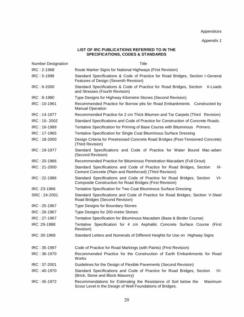
LIST OF IRC PUBLICATIONS REFERRED TO IN THESPECIFICATIONS, CODES & STANDARDS
Number Designation TitleIRC : 2-1968 Route Marker Signs for National Highways (First Revision)IRC : 5-1998 Standard Specifications & Code of Practice for Road Bridges, Section I -General
Features of Design (Seventh Revision)IRC : 6-2000 Standard Specifications & Code of Practice for Road Bridges, Section II-Loads
and Stresses (Fourth Revision)IRC : 8-1980 Type Designs for Highway Kilometre Stones (Second Revision)IRC : 10-1961 Recommended Practice for Borrow pits for Road Embankments Constructed by
Manual OperationIRC : 14-1977 Recommended Practice for 2 cm Thick Bitumen and Tar Carpets (Third Revision)IRC : 15- 2002 Standard Specifications and Code of Practice for Construction of Concrete Roads.IRC : 16-1989 Tentative Specification for Priming of Base Course with Bituminous Primers.IRC : 17-1965 Tentative Specification for Single Coat Bituminous Surface DressingIRC : 18-2000 Design Criteria for Prestressed Concrete Road Bridges (Post-Tensioned Concrete)
(Third Revision)IRC : 19-1977 Standard Specifications and Code of Practice for Water Bound Mac-adarn
(Second Revision)IRC : 20-1966 Recommended Practice for Bituminous Penetration Macadam (Full Grout)IRC : 21-2000 Standard Specifications and Code of Practice for Road Bridges, Section III-
Cement Concrete (Plain and Reinforced) (Third Revision)IRC : 22-1986 Standard Specifications and Code of Practice for Road Bridges, Section VI-
Composite Construction for Road Bridges (First Revision)IRC :23-1966 Tentative Specification for Two Coat Bituminous Surface DressingSRC : 24-2001 Standard Specifications and Code of Practice for Road Bridges, Section V-Steel
Road Bridges (Second Revision)IRC : 25-1967 Type Designs for Boundary StonesIRC : 26-1967 Type Designs for 200-metre StonesIRC : 27-1967 Tentative Specification for Bituminous Macadam (Base & Binder Course)IRC :29-1988 Tentative Specification for 4 cm Asphaltic Concrete Surface Course (First
Revision)IRC :30-1968 Standard Letters and Numerals of Different Heights for Use on Highway Signs
IRC : 35-1997 Code of Practice for Road Markings (with Paints) (First Revision)IRC : 36-1970 Recommended Practice for the Construction of Earth Embankments for Road
WorksIRC : 37-2001 Guidelines for the Design of Flexible Pavements (Second Revision)IRC : 40-1970 Standard Specifications and Code of Practice for Road Bridges, Section IV-
(Brick, Stone and Block Masonry)IRC : 45-1972 Recommendations for Estimating the Resistance of Soil below the Maximum
Scour Level in the Design of Well Foundations of Bridges.
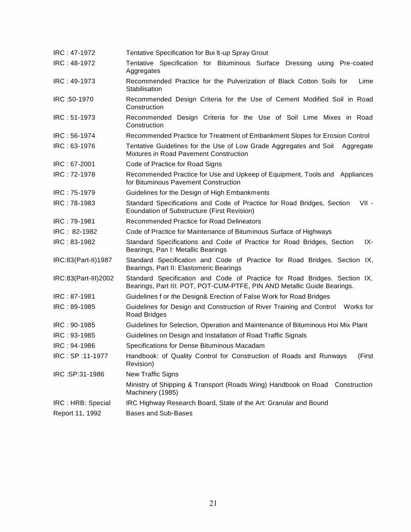
IRC : 47-1972 Tentative Specification for Bui lt-up Spray GroutIRC : 48-1972 Tentative Specification for Bituminous Surface Dressing using Pre-coated
AggregatesIRC : 49-1973 Recommended Practice for the Pulverization of Black Cotton Soils for Lime
StabilisationIRC :50-1970 Recommended Design Criteria for the Use of Cement Modified Soil in Road
ConstructionIRC : 51-1973 Recommended Design Criteria for the Use of Soil Lime Mixes in Road
ConstructionIRC : 56-1974 Recommended Practice for Treatment of Embankment Slopes for Erosion ControlIRC : 63-1976 Tentative Guidelines for the Use of Low Grade Aggregates and Soil Aggregate
Mixtures in Road Pavement ConstructionIRC : 67-2001 Code of Practice for Road SignsIRC : 72-1978 Recommended Practice for Use and Upkeep of Equipment, Tools and Appliances
for Bituminous Pavement ConstructionIRC : 75-1979 Guidelines for the Design of High EmbankmentsIRC : 78-1983 Standard Specifications and Code of Practice for Road Bridges, Section VII -
Eoundation of Substructure (First Revision)IRC : 79-1981 Recommended Practice for Road DelineatorsIRC : 82-1982 Code of Practice for Maintenance of Bituminous Surface of HighwaysIRC : 83-1982 Standard Specifications and Code of Practice for Road Bridges, Section IX-
Bearings, Pan I: Metallic BearingsIRC:83(Part-II)1987 Standard Specification and Code of Practice for Road Bridges. Section IX,
Bearings, Part II: Elastomeric BearingsIRC:83(Part-III)2002 Standard Specification and Code of Practice for Road Bridges. Section IX,
Bearings, Part III: POT, POT-CUM-PTFE, PIN AND Metallic Guide Bearings.IRC : 87-1981 Guidelines f or the Design& Erection of False Work for Road BridgesIRC : 89-1985 Guidelines for Design and Construction of River Training and Control Works for
Road BridgesIRC : 90-1985 Guidelines for Selection, Operation and Maintenance of Bituminous Hoi Mix PlantIRC : 93-1985 Guidelines on Design and Installation of Road Traffic SignalsIRC : 94-1986 Specifications for Dense Bituminous MacadamIRC : SP :11-1977 Handbook: of Quality Control for Construction of Roads and Runways (First
Revision)IRC :SP:31-1986 New Traffic Signs
Ministry of Shipping & Transport (Roads Wing) Handbook on Road ConstructionMachinery (1985)
IRC : HRB: Special IRC Highway Research Board, State of the Art: Granular and BoundReport 11, 1992 Bases and Sub-Bases

Appendix 2LIST OF INDIAN AND FOREIGN STANDARDS REFERRED TO
IN THE SPECIFICATIONS
Number Designation Title(A) INDIAN STANDARDS
IS:5-1994 Colour for ready mixed paint and enamels (fourth revision)IS:73-1992 Paving Bitumen-Specification (second revision)IS:73-1992 Ready mixed paints, brushing, for road marking, to Indian Standard
Colour No. 356 Golden yellow, white and blackIS:210-1993 Grey iron castings (fourth revision)IS:215-1995 Road tar specification (third revision)IS:217-1988 Cutback Bitumen-Specification (second revision)IS:269-1989 33 grade ordinary Portland cement (fourth revision)IS:278-1978 Galvanized steel barbed wire for fencing (third revision)IS:280-1978 Mild steel wire for general engineering purposes (third revision)IS:334-1982 Glossary of terms relating to Bitumen and tar (second revision)IS:383-1970 Coarse and fine aggregates from natural sources for concrete (second
revision)IS:432-1982 Mild steel and medium tensile steel bars and hard-drawn steel wire for
concrete reinforcement(Part I) Mild steel and medium tensile steel bars (third revision)(Part II) Hard-drawn steel wire (third revision)IS:443-1975 Methods of sampling and test for rubber house (second revision)IS:454-1994 Cutback Bitumen from Waxy Crude-Specification (second revision)IS:455-1989 Portland stag cement (fourth revision)IS:456-2000 Code of practice for plain and reinforced concrete (fourth revision)IS:458-1988 Precast Concrete pipes (with and without reinforcement) (third revision)IS:460-1985 Test sievesIS:508-1987 Specification grease graphited (fourth revision)IS:516-1959 Methods of test for strength of concreteIS:702-1988 Industrial bitumen (second revision)IS:736-1986 Wrought aluminum and aluminum alloys, plates for general engineering
purposes (third revision)IS:814-1991 Covered electrodes for manual metal are welding of carbon and carbon
manganese steel (fifth revision)IS:1030-1998 Carbon steel casting for general engineering purposes (fifth revision)IS:1077-1992 Common burnt clay building brick (fifth revision)IS:1124-1974 Method of test for water absorption apparent specific gravity and porosity
of natural building stone (first revision)IS:1129-1972 Dressing of natural building stone (first revision)IS:1148-1982 Hot rolled rivet bars (upto 40 mm dia) for structural purposes (third
revision)IS:1149-1982 High tensile rivet bars for structural purposes (third revision)IS:1195-1978 Bitumen mastic for flowing (second revision)IS:1199-1959 Method of sampling and analysis of concreteIS:1201 to 1220-1978 Indian standard methods for testing tar and bituminous materialsIS:1203-1978 Determination of penetration (first revision)IS:1205-1978 Determination of softening point (first revision)IS:1206-1978(Part 1 to 3)
Determination of viscosity (first revision)
IS:1208-1978 Determination of ductility (first revision)IS:1209-1978 Determination of flash point & fire point (first revision)IS:1212-1978 Determination of lose of heating (first revision)
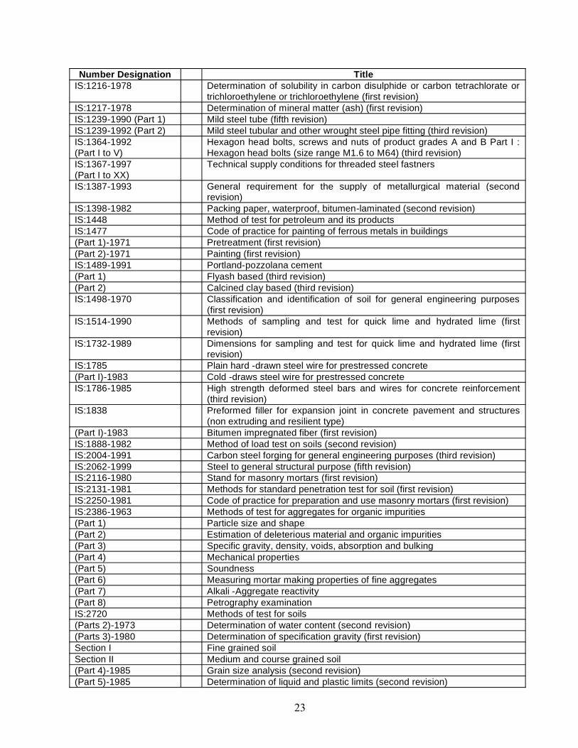
Number Designation TitleIS:1216-1978 Determination of solubility in carbon disulphide or carbon tetrachlorate or
trichloroethylene or trichloroethylene (first revision)IS:1217-1978 Determination of mineral matter (ash) (first revision)IS:1239-1990 (Part 1) Mild steel tube (fifth revision)IS:1239-1992 (Part 2) Mild steel tubular and other wrought steel pipe fitting (third revision)IS:1364-1992(Part I to V)
Hexagon head bolts, screws and nuts of product grades A and B Part I :Hexagon head bolts (size range M1.6 to M64) (third revision)
IS:1367-1997(Part I to XX)
Technical supply conditions for threaded steel fastners
IS:1387-1993 General requirement for the supply of metallurgical material (secondrevision)
IS:1398-1982 Packing paper, waterproof, bitumen-laminated (second revision)IS:1448 Method of test for petroleum and its productsIS:1477 Code of practice for painting of ferrous metals in buildings(Part 1)-1971 Pretreatment (first revision)(Part 2)-1971 Painting (first revision)IS:1489-1991 Portland-pozzolana cement(Part 1) Flyash based (third revision)(Part 2) Calcined clay based (third revision)IS:1498-1970 Classification and identification of soil for general engineering purposes
(first revision)IS:1514-1990 Methods of sampling and test for quick lime and hydrated lime (first
revision)IS:1732-1989 Dimensions for sampling and test for quick lime and hydrated lime (first
revision)IS:1785 Plain hard -drawn steel wire for prestressed concrete(Part I)-1983 Cold -draws steel wire for prestressed concreteIS:1786-1985 High strength deformed steel bars and wires for concrete reinforcement
(third revision)IS:1838 Preformed filler for expansion joint in concrete pavement and structures
(non extruding and resilient type)(Part I)-1983 Bitumen impregnated fiber (first revision)IS:1888-1982 Method of load test on soils (second revision)IS:2004-1991 Carbon steel forging for general engineering purposes (third revision)IS:2062-1999 Steel to general structural purpose (fifth revision)IS:2116-1980 Stand for masonry mortars (first revision)IS:2131-1981 Methods for standard penetration test for soil (first revision)IS:2250-1981 Code of practice for preparation and use masonry mortars (first revision)IS:2386-1963 Methods of test for aggregates for organic impurities(Part 1) Particle size and shape(Part 2) Estimation of deleterious material and organic impurities(Part 3) Specific gravity, density, voids, absorption and bulking(Part 4) Mechanical properties(Part 5) Soundness(Part 6) Measuring mortar making properties of fine aggregates(Part 7) Alkali -Aggregate reactivity(Part 8) Petrography examinationIS:2720 Methods of test for soils(Parts 2)-1973 Determination of water content (second revision)(Parts 3)-1980 Determination of specification gravity (first revision)Section I Fine grained soilSection II Medium and course grained soil(Part 4)-1985 Grain size analysis (second revision)(Part 5)-1985 Determination of liquid and plastic limits (second revision)
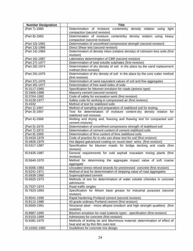
Number Designation Title(Part 7)-1980 Determination of moisture content/dry density relation using light
compaction (second revision)(Part 8)-1983 Determination of moisture content/dry density relation using heavy
compaction (second revision)(Part 10)-1991 Determination of unconfined compressive strength (second revision)(Part 13)-1986 Direct Shear test (second revision)(Part 14)-1983 Determination of density inbox (relative density) of cohesion less soils (first
revision)(Part 16)-1987 Laboratory determination of CBR (second revision)(Part 27)-1977 Determination of total soluble sulphates (first revision)(Part 28)-1974 Determination of dry density of soil in the place by the sand replacement
method (first revision)(Part 29)-1975 Determination of dry density of soil in the place by the core cutter method
(first revision)(Part 37)-1976 Determination of sand equivalent values of soil and fine aggregates(Part 40)-1977 Determination of free swell index of soilsIS:3117-1965 Specification for bitumen emulsion for roads (anionic type)IS:3466-1988 Masonry cement (second revision)IS:3764-1992 Code of safety for excavation work (first revision)IS:4138-1977 Safety code for working in compressed air (first revision)IS:4332 Method of test for stabilized soils(Part 1)-1967 Method of sampling and preparation of stabilized soil for testing.(Part 3)-1967 Test for determination of moisture content-dry density relation for
stabilized soil mixtures(Part 4)-1968 Wetting and drying and, freezing and thawing test for compacted soil-
cement mixtures(Part 5)-1970 Determination of unconfined compressive strength of stabilized soil(Part 7)-1973 Determination of cement content of cement stabilized soils(Part 8)-1969 Determination of lime content of lime stabilized soilsIS:4434-1978 Code of practice for in-situ van shear test for soil (first revision)IS:4826-1979 Hot dipped galvanized coating on round steel wires (first revision)IS:5317-1987 Specification for bitumen mastic for bridge decking and roads (first
revision)IS:5435-1987 General requirements for cold asphalt macadam mixing plants (first
revision)IS:5640-1970 Method for determining the aggregate impact value of soft coarse
aggregateIS:6006-1983 Uncoated stress relived strands for prestressed concrete (first revision)IS:6241-1971 Method of test for determination of stripping value of road aggregatesIS:6939-1990 Supersulphated cementIS:6925-1973 Methods of test for determination of water soluble chlorides in concrete
admixturesIS:7537-1974 Road traffic singlesIS:7623-1993 Specification for lithium base grease for industrial purposes (second
revision)IS:8041-1990 Rapid hardening Portland cement (second revision)IS:8112-1989 43 grade ordinary Portland cement (first revision)IS:8500-1991 Structural steel - micro alloyed (medium and high strength qualities) (first
revision)IS:8887-1995 Bitumen emulsion for road (cationic type) - specification (first revision)IS:9103-1999 Admixtures for concrete (first revision)IS:9381-1979 Methods of testing tar and bituminous material: determination of effect of
heat and air by thin film oven testIS:10262-1982 Guidelines for concrete mix design

Number Designation TitleIS:12269-1987 Specification for 53 grade ordinary Portland cementIS:12330-1988 Specification for sulphate resisting Portland cementIS:13321 (Part I)-1992 Glossary of term for geosynthetics, part I : terms used in materials and
propertiesIS:13325-1992 Determination of tensile properties of extruded polymer geogrids using the
wide strip-test methodIS:13326 (Part I)-1992 Evolution of interface frication between geosynthetics and soil- method of
test, part I : modified direct shear techniqueIS:SP 23-1982 Handbook on concrete mixes (based on Indian standards)
FOREIGEN STANDERDSASTM : D-36 Thermoplastic materialASTM : D-395 Compression test of vulcanized rubberASTM : D-412 Tension testing of vulcanized rubberASTM : D-429 Adhesion of vulcanized rubber to metalASTM : D-573 Accelerated aging of vulcanized rubber by the oven methodASTM : D-624 Tear resistance of vulcanized rubberASTM : D-664 Test method for neutralization number for potentiometric titrationASTM : D-797 Young’s modulus in flexure of elastomer at normal and subnormal
temperatureASTM : D977-91 Standard specification for emulsified asphaltASTM:D979-89 Standard practice for sampling bituminous paving mixturesASTM:D-1075 Effect of water on cohesion of compacted bituminous mixtureASTM:D1149 Accelerated ozone creaking of vulcanized rudderASTM:D-1559 Test of resistance to plastic flow of bituminous mixture using Marshall
apparatusASTM:D-2026-72 Standard specification for cutback asphalt (Show-curing type)ASTM:D2027-76 Standard specification for cutback asphalt (Medium-curing type)ASTM:D2041-95 Standard test method for theoretical maximum specific gravity and density
of bituminous paving mixturesASTM:D2172-95 Standard test method for quantitative extraction of bitumen from
bituminous paving mixturesASTM:D-2240 Indentation hardness of rudder and plastic by means of a DurometerASTM:D2397-94 Standard specification of cationic emulsified asphaltASTM:D3203-94 Standard test method for per cent air voids in compacted dense and open
bituminous paving mixturesASTM:D-3625 Test method for effect of water on bitumen coated aggregated using
boiling waterASTM:D3910-90 Standard practice for design testing and construction of slurry sealASTM:D-4533 Test method for trapezoid tearing strength of geotextilesASTM:D5976-96 Standard specification for type I polymer modified asphalt cement for use
in pavement constructionASTM:E-11 Specification for wire cloth sieves for testing purposesASTM:E-810 Test method for coefficient of retro-reflection or retro-reflection sheetingAASHTO:DM283 Coarse aggregate for highway and airport constructionAASHTO:DM294-70 Fine aggregate for bituminous paving mixturesAASHTO:DM288-82 Geotextiles used for subsurface drainage purposesAASHTO:DM17-77 Mineral filler for bituminous paving mixturesAASHTO:DR5-80 Selection and use of emulsified asphaltsAASHTO:DM81-75 Cut-back asphalt (rapid-curing type)AASHTO:DM82-75 Cut-back asphalt (Medium-curing type)AASHTO:DM140-80 Emulsified asphaltAASHTO:DM57-80 Materials for embankments and sub gradesAASHTO:DM147-65 Materials for aggregate and soil-aggregate sub base and surfaceAASHTO:DM216-68 Lime for stabilization
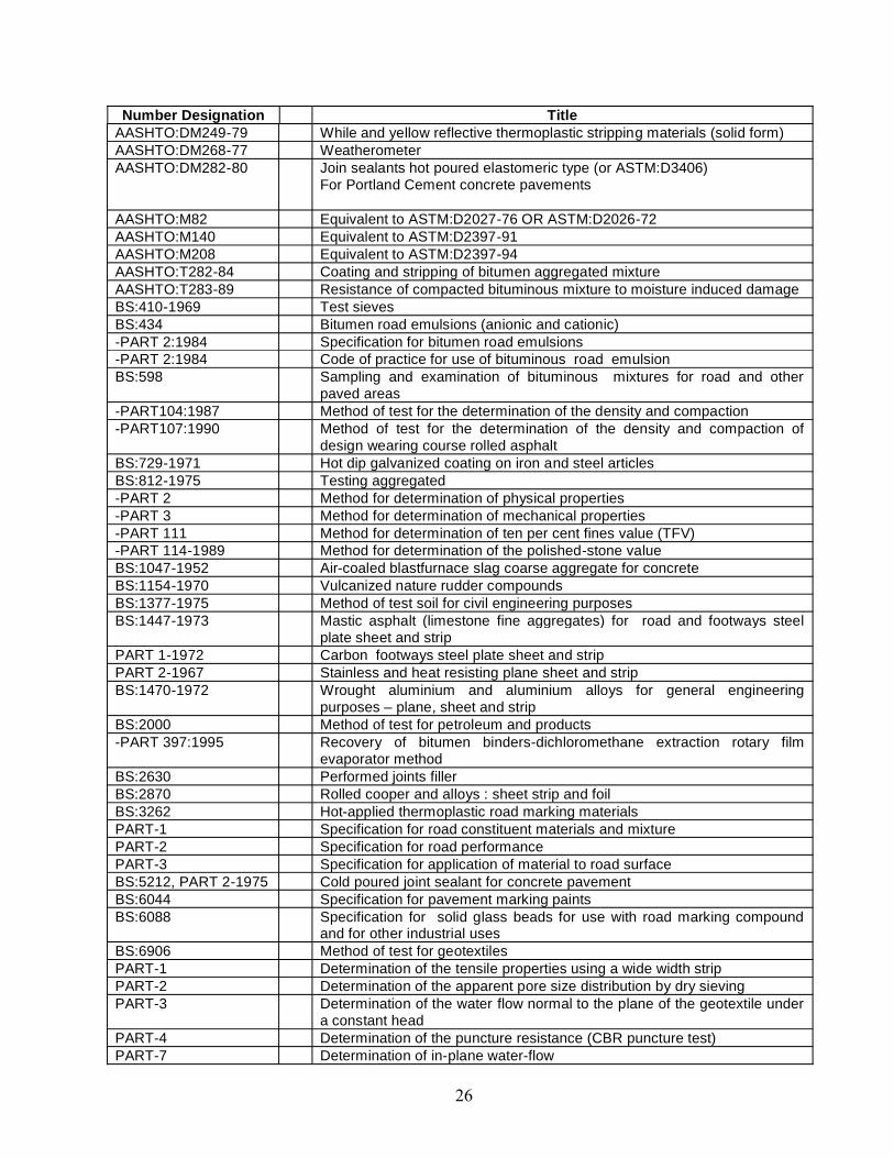
Number Designation TitleAASHTO:DM249-79 While and yellow reflective thermoplastic stripping materials (solid form)AASHTO:DM268-77 WeatherometerAASHTO:DM282-80 Join sealants hot poured elastomeric type (or ASTM:D3406)
For Portland Cement concrete pavements
AASHTO:M82 Equivalent to ASTM:D2027-76 OR ASTM:D2026-72AASHTO:M140 Equivalent to ASTM:D2397-91AASHTO:M208 Equivalent to ASTM:D2397-94AASHTO:T282-84 Coating and stripping of bitumen aggregated mixtureAASHTO:T283-89 Resistance of compacted bituminous mixture to moisture induced damageBS:410-1969 Test sievesBS:434 Bitumen road emulsions (anionic and cationic)-PART 2:1984 Specification for bitumen road emulsions-PART 2:1984 Code of practice for use of bituminous road emulsionBS:598 Sampling and examination of bituminous mixtures for road and other
paved areas-PART104:1987 Method of test for the determination of the density and compaction-PART107:1990 Method of test for the determination of the density and compaction of
design wearing course rolled asphaltBS:729-1971 Hot dip galvanized coating on iron and steel articlesBS:812-1975 Testing aggregated-PART 2 Method for determination of physical properties-PART 3 Method for determination of mechanical properties-PART 111 Method for determination of ten per cent fines value (TFV)-PART 114-1989 Method for determination of the polished-stone valueBS:1047-1952 Air-coaled blastfurnace slag coarse aggregate for concreteBS:1154-1970 Vulcanized nature rudder compoundsBS:1377-1975 Method of test soil for civil engineering purposesBS:1447-1973 Mastic asphalt (limestone fine aggregates) for road and footways steel
plate sheet and stripPART 1-1972 Carbon footways steel plate sheet and stripPART 2-1967 Stainless and heat resisting plane sheet and stripBS:1470-1972 Wrought aluminium and aluminium alloys for general engineering
purposes – plane, sheet and stripBS:2000 Method of test for petroleum and products-PART 397:1995 Recovery of bitumen binders-dichloromethane extraction rotary film
evaporator methodBS:2630 Performed joints fillerBS:2870 Rolled cooper and alloys : sheet strip and foilBS:3262 Hot-applied thermoplastic road marking materialsPART-1 Specification for road constituent materials and mixturePART-2 Specification for road performancePART-3 Specification for application of material to road surfaceBS:5212, PART 2-1975 Cold poured joint sealant for concrete pavementBS:6044 Specification for pavement marking paintsBS:6088 Specification for solid glass beads for use with road marking compound
and for other industrial usesBS:6906 Method of test for geotextilesPART-1 Determination of the tensile properties using a wide width stripPART-2 Determination of the apparent pore size distribution by dry sievingPART-3 Determination of the water flow normal to the plane of the geotextile under
a constant headPART-4 Determination of the puncture resistance (CBR puncture test)PART-7 Determination of in-plane water-flow

Number Designation TitleBS:7542 Method of test curing compound for concreteCRR I & IOCNew Delhi
Bituminous road construction hand book
BS:DD232-1996 Method for determination of the maximum binder content of bituminousmixture with out excessive binder brainage
Asphalt Institute The asphalt handbook , manual Series No.4(MS-4) 1989 edition manualSeries No.2(MS-2) – mix design method for asphalt concrete and otherhot-mix typeManual series No.14 (MS-14) – asphalt cold mix manual
GRI-GG1 Geogrid rip tensile strengthGRI-GG2 Geogrid junction strengthGRI-GG3 Tensile creep testing of geogrids

200 Site clearance

CONTENT
Clause No Description201 Scope of work202 DISMANTLING CULVERTS, BRIDGES AND OTHER STRUCTURES
/PAVEMENTS203 Summary of Site Clearance
201.1 Scope of workLand for road embankment, drains, cross-drainage structures and such structure of road should becleared of all materials unsuitable for the work by cutting, trimming, removing and disposing of allmaterials, such as trees, bushes, shrubs, stumps, roots, grass, weeds, top organic soil not exceeding150 mm in thickness and rubbish, etc. This should be carried out well in advance of earthworkoperations. It shall include necessary excavation, backfilling of pits resulting from uprooting of trees andstumps to required compaction, handling, salvaging, and disposal of cleared materials with all leadsand lift.
201.2 Preservation of Property/AmenitiesRoadside trees, shrubs, pole lines, fences, signs, monuments, buildings, pipelines, sewers and all roadfacilities within or adjacent to the road which are not to be disturbed shall be protected from injury ordamage. The Contractor shall provide and install at his own cost, suitable safeguards approved by theEngineer in charge of local body for this purpose.
During clearing and grubbing, the Contractor shall take all adequate precautions against soil erosion,water pollution, etc., and where required, undertake additional works to that effect vide Clause 306.Before start of work, the Contractor shall submit to the Engineer in charge for approval, his work planincluding the procedure to be followed for disposal of waste materials, etc., and the schedules forcarrying out temporary and permanent erosion control works as stipulated in Clause 306.3.
201.3 Methods, Tools and Equipment(i) Only such methods, tools and equipment as are approved by the Engineer and which will not affectthe property to be preserved shall be adopted for the Work.
(ii) If the area has thick vegetation/roots/trees, a crawler or pneumatic tyred dozer of adequate capacitymay be used for clearance purposes.
(iii) The dozer shall have ripper attachments for removal of tree stumps. All trees, stumps, etc., fallingwithin excavation and fill lines shall be cut to such depth below ground level that in no case these fallwithin 500 mm of the sub-grade.
(iv) Also, all vegetation such as roots, under-growth, grass and other deleterious matter unsuitable forincorporation in the embankment/sub-grade shall be removed between fill lines to the satisfaction of theEngineer in charge.
(v) On areas beyond these limits, trees and stumps required to be removed as directed by the Engineerin charge shall be cut down to 1 m below ground level so that these do not present an unsightlyappearance.
(vi) All excavations below the general ground level arising out of the removal of trees, stumps, etc.,shall be filled with suitable material and compacted thoroughly so as to make the surface at thesepoints conform to the surrounding area.
(vii) Ant-hills both above and below the ground, as are liable to collapse and obstruct free subsoil waterflow shall be removed and their workings, which may extend to several meters, shall be suitablytreated.
201.4. Disposal of Materials(i) All materials arising from clearing and grubbing operations shall be the property of local body. It shallbe disposed of by the Contractor as hereinafter provided or directed by the Engineer in charge.
(ii) Trunks, branches and stumps of trees shall be cleaned of limbs and roots and slacked.
(iii) Boulders, stones and other materials usable in road construction shall be neatly stacked as directedby the Engineer in charge.
(iv) Stacking of stumps, boulders, stones etc., shall be done at specified spots with all lifts and up to alead of 1000 m.
(v) All products of clearing and grubbing which, in the opinion of the Engineer, cannot be used orauctioned shall be cleared away from the roadside in a manner as directed by the Engineer in charge.
201.5. Measurements for Payment(i) Clearing and grubbing shall be measured in terms of hectares.
(ii) Clearing and grubbing of borrow areas shall not be paid because it is included in the rate quoted forthe embankment construction item.
(iii) Cutting of trees up to 300 mm in girth including removal of stumps and roots, and trimming ofbranches of trees extending above the roadway shall be considered incidental to the clearing andgrubbing operations. Removal of stumps left over after trees have been cut by any other agency shallalso be considered incidental to the clearing and grubbing operations.
(iv) Cutting, including removal of stumps and roots of trees of girth above 300 mm and backfilling torequired compaction shall be measured in terms of number according to the sizes given below: -
i) Above 300 mm to 600 mmii) Above 600 mm to 900 mmiii) Above 900 mm to 1800 mmiv) Above 1800 mm
For this purpose, the girth shall be measured at a height of 1 meter above ground or at the top of thestump if the height of the stump is less than one meter from the ground.
201.6. Rates201.6.1(i) The Contract unit rates for the various items of clearing and grubbing shall be payment in full forcarrying out the required operations including full compensation for all labour, materials, tools,equipment and incidentals necessary to complete the work.
(ii) These will also include removal of stumps of trees less than 300 mm in girth as Well as stumps leftover after cutting of trees carried out by another agency, excavation and back-filling to required density,where necessary, and handling, salvaging, piling and disposing of the cleared materials with all lifts andup to a lead of 1000 m.
(iii) The Contract unit rate for cutting (including removal of stumps and roots) of trees of girth above 300mm shall include excavation and backfilling to required compaction, handling, salvaging, piling anddisposing of the cleared materials with all lifts and up to a lead of 1000 m.
(iv) Where a Contract does not include separate items of clearing and grubbing, the same shall beconsidered incidental to the earthwork items and the Contract unit prices for the same shall beconsidered as including clearing and grubbing operations.
202. DISMANTLING CULVERTS, BRIDGES AND OTHER STRUCTURES/PAVEMENTS202.1. Scope(i) This work shall consist of removing existing structure like culverts, bridges, kerbs, guard-rails,fences, utility services, manholes, catch basins, inlets, etc., and pavements which are in place butinterfere with the new construction or are not suitable to remain in place. This shall include salvagingand disposing of the resulting materials and back filling the resulting trenches and pits.
(ii) Dismantling shall be done up to the limits and extent specified in the drawings or as indicated by theEngineer in charge.
(iii) Dismantling and removal operations shall be carried out with such equipment and in such a manneras to leave undisturbed, adjacent pavement, structures and any other work to be left in place.
(iv) All operations necessary for the removal of any existing structure which might endanger newconstruction shall be completed prior to the start of new work.
202.2. Dismantling Culverts and Bridges(i) Existing structures which are within the road land and designated for removal should be dismantledcarefully and the resulting materials so removed as not to cause any damage to the serviceablematerials to be salvaged, the parts of the structure to be retained and any other adjoining propertiesand utilities.
(ii)(a) Where existing culverts/bridges are to be extended or otherwise incorporated in the new work,only such part or parts of the existing structure shall be removed as are necessary and directed by theEngineer in charge to provide a proper connection to the new work.
(ii)(b) The connecting edges shall be cut, chipped and trimmed to the required lines and grades withoutweakening or damaging any part of the structure to be retained. Due care should be taken to ensurethat reinforcing bars which are to be left in place so as to project into the new work as dowels or ties arenot injured during removal of concrete.
(iii) Pipe culverts shall be carefully removed in such a manner as to avoid damage to the pipes.
(iv)(a) Steel structures shall, unless otherwise provided, be carefully dismantled in such a manner as toavoid damage to members thereof.
(iv)(b) If specified in the drawings or directed by the Engineer in charge that the, structure is to beremoved in a condition suitable for re-erection, all members shall be match-marked by the Contractorwith white lead paint before dismantling.
(v)(c) End pins, nuts, loose plates, etc., shall be similarly marked to indicate their proper location; allpins, pin holes and machined surfaces shall be painted with a mixture of white lead and tallow and allloose parts shall be securely wired to adjacent members or packed in boxes.
202.3. Dismantling Pavements and Other Structures(i) All concrete pavements, base courses in carriageway and shoulders etc., designated for removalshall be broken to pieces whose volume shall not exceed 0.02 cu. m. and stockpiled at designatedlocations if the material is to be used later or otherwise arranged for disposal as directed by Engineer incharge.
(ii) In removing the kerbs, gutters, and other structures like guard-rails, fences, manholes, catch basins,inlets are their parts shall be dismantle as directed by the Engineer in charge.
202.4. Back-fillingHoles and depressions caused by dismantling operations shall be backfilled with excavated or otherapproved materials and compacted to required density as directed by the Engineer in charge.
202.5. Disposal of Materials(i) All materials obtained by dismantling shall be the property of local body.
(ii) Unless otherwise specified, materials having any salvage value shall be placed in neat stacks of likematerials within the right of-way, as directed by the Engineer in charge with all lifts and up to a lead of1000 m.
(iii) Pipe culverts that are removed shall be cleaned and neatly piled on the right of way at pointsdesignated by the Engineer in charge with all lifts and leads up to 1000 m.
(iv) Structural steel removed from old structures shall, unless otherwise specified or directed, be storedin a neat and presentable manner on blocks in locations suitable for loading. Structures or portions(hereof which are specified in the Contract for re -erection shall be stored in separate piles.
(v) All materials obtained from dismantling operations which, in the opinion of the Engineer cannot beused or auctioned shall be disposed of as directed by the Engineer in charge widi all lifts and up to alead of 1000 m.
202.6. Measurements for PaymentThe work of dismantling structures shall be paid for in units indicated below by taking measurementsbefore and after, as applicable:
(i) Dismantling brick/stone masonry/concrete (plain and reinforced) cu. m.(ii) Dismantling flexible and cement concrete pavement cu. m.(iii) Dismantling steel structures tonne(iv) Dismantling limber structures cu. m.(v) Dismantling pipes, guard rails, kerbs, gutters and fencing linear m.(vi) Utility services Nos.
202.7. Rates(i) The Contract unit rates for the various items of dismantling shall be paid in full for carrying out therequired operations including full compensation for all labour, materials, tools, equipment, safeguardsand incidents necessary to complete the work.
(ii) These will also include excavation and backfilling where necessary to the required compaction andfor handling, salvaging, piling and disposing of the dismantled materials within all lifts and up to a leadof 1000 m.
Summary of Site Clearance1. The road land should be cleared of all materials unsuitable for the work by cutting, trimming,removing and disposing of all materials, such as trees, bushes, shrubs, stumps, roots, grass, weeds,top organic soil not exceeding 150 mm in thickness and rubbish, etc. This should be carried out well inadvance of earthwork operations.
2. The top soil removed during clearing and grubbing of site, if suitable for re-use shall be transported,conserved and stacked for re-use.
3. All trees, stumps, etc. falling within the excavation and embankment lines should be cut to suchdepth below ground level that in no case these fall within 500 mm of the sub-grade. Beyond theselimits, they need to be cut down to 500 mm below ground level.
4. Excavations below the ground level arising out of removal of trees, stumps, etc., should be filled inlayers with suitable material and compacted to the specified density given by the Engineer.
5. Measurement of trees having girth more than 300 mm should be done as per sizes given in the Bill ofQuantities (BOQ).
6. Ant-hills both above and below the ground shall be removed by excavating to a suitable depth asdirected by the Engineer. Cavities in the ground after removal of ant-hills shall be filled with appropriatematerial and properly compacted to the specified density.
7. Existing structures which are within the road land and designated for removal should be dismantledcarefully and the resulting materials so removed as not to cause any damage to the serviceablematerials to be salvaged, the parts of the structure to be retained and any other adjoining propertiesand utilities.
8. Holes and depressions caused by dismantling operations or caused by rats etc. shall be backfilledwith approved material and compacted to the required density.
9. Obtain prior permission of the competent authority for removing/disturbing any existing utilities etc.required.
10. Conserve top-soil for re-use where suitable.
11. Do not disturb existing poles, fences, signs, monuments, buildings, pipelines, sewers, and trees etc.which do not interfere with the work and are to be retained.
12. Do not damage parts of existing structures to be retained while dismantling portions interfering withthe work.

300. EARTH WORK, EROSION CONTROL ANDDRAINAGE

CONTENT
Clause No Description301 EXCAVATION FOR ROADWAY AND DRAIN
302 BLASTING OPERATIONS
303 PRESPLITTING ROCK EXCAVATION SLOPES
304 EXCAVATION FOR STRUCTURES
305 EMABANKMENT CONSTRUCTION
306 SOIL EROSION AND SEDIMENTATION CONTROL.
307 TURFING WITH SODS
308 SEEDING AND MULCHING
309 SURFACE/SUB-SURFACE DRAINS
301. EXCAVATION FOR ROADWAY AND DRAIN301.1 ScopeExcavation for Roadway and Drains shall include excavation, removal and disposal of materialsnecessary for the construction of roadway, side drains and waterways in accordance with requirementsof these Specifications and the lines, grades and cross-sections shown in the drawings or as indicatedby the Engineer. The cut material may be taken away by the Contractor for re-use or disposal.
301.2 Classification of Excavated Material301.2.1 Classification: Excavated Material shall be classified by the Engineer in Charge of Local body inthe following category:
i) Soil:ii) Ordinary Rockiii) Hard Rockiii-a) Hard Rock (Requiring blasting)iii-b) Hard Rock (using controlled blasting)iii-c) Hard Rock (blasting prohibited)iv) Marshy soil
Details of each category of strata are as below:-(i) SoilGenerally any soil which yield to the ordinary application of pick spade and/or shovel, rake or otherordinary digging equipment. Such as turf, sand, silt, loam, clay, mud, peat, black, cotton soil, soft shaleor loose moorum, a mixture of these, Removal of gravel or any other modular material having dimensionin any one direction not exceeding 75mm shall be deemed to be covered under this category.
(ii) Ordinary Rock (not requiring blasting) This shall include:i) Includes such strata which requires the close application of crow bars, grafting tool or picks or
both and shovel, such as laterites, shales and conglomerates, varieties of limestone, sandstone, WBMbitumen / tar bound macadam, soling of roads, paths, hard core, compact moorum or stabilized soil ,gravel, cobble stone, lime concrete, stone masonry in lime mortar, brick work in lime/ cement mortarbelow ground level, reinforced cement concrete which may be broken up with crow bars or picks, stonemasonry in cement mortar below ground level, loose are emended boulders which do not requireblasting and any rock which in dry state may be hard, requiring blasting but which, when wet, becomessoft and manageable by means other than blasting.
(iii-a) Hard Rock (requiring blasting) This shall comprise:(a) Any rock or boulder which requires the use of mechanical plant or blasting of for the excavationor splitting.(b) Reinforced cement concrete (reinforcement cut through but not separated from the concrete)below ground level;(iii-b) Hard Rock (using controlled blasting):Hard rock requiring blasting as described under (c) but where controlled blasting is to be carried outlocations where built-up area, huts, abodes of people and livestock at within 200 m.
(iii-c) Hard Rock (blasting prohibited)Hard rock requiring blasting as described under (d) but where blasting is prohibited for any reason likepeople living within 20 m of blast sites etc. and excavation has to be carried out by chiseling, wedging orany other agreed method.
(iv) Marshy soilMarshy soil shall include soils like soft clays and peats excavated below the original ground level ofmarshes and swamps and soils excavated from other areas requiring continuous pumping or bailing outof water.
301.2.2 Authority for classification: The classification of excavation shall be decided by the Engineer incharge of Local Body (Municipal Corporation, Municipal Council, Municipal Nagar Panchayat) and hisdecision shall be final and binding on the Contractor. Merely the use of explosives in excavation will notbe considered as a reason for higher classification unless blasting is clearly necessary in the opinion ofthe Engineer.
301.3 Construction Operations301.3.1 Setting out: After site clearance as per Clause 200, the limits of excavation shall be set out trueto lines, curves, slopes, grades and sections as per approved drawings or as directed by the Engineerin charge. The Contractor shall provide all labour, survey instruments and materials such as strings,pegs, nails, bamboos, stones, lime, mortar, concrete, etc., required in connection with the setting out ofworks and the establishment of bench marks. The Contractor shall be responsible for the maintenanceof bench marks and other marks and stakes as long as in the opinion of the Engineer in charge, whichare required for the works.
301.3.2 Stripping and storing topsoil : If as directed by the Engineer in charge, the topsoil existing overthe sites of excavation shall be stripped to specified depths constituting Horizon “A” and stockpiled atdesignated locations for re-use in covering embankment slopes, cut slopes, berms and other location asdesired by Engineer in Charge. Prior to stripping site clearance shall be done as per clause 200.
301.3.3 Excavation – Brief: The excavations shall conform to the lines, grades, side slopes and levelsshown on the drawings or as directed by the Engineer in charge. The Contractor shall not excavateoutside the limits of excavation. Subject to the permitted tolerances, any excess depth/width excavatedbeyond the specified levels/dimensions on the drawings shall be made good at the cost of theContractor with suitable material of characteristics similar to that removed and compacted to therequirements of Clause 305.
All debris and loose material on the slopes of cuttings shall be removed. No backfilling shall be allowedto obtain required slopes excepting that when boulders or soft materials are encountered in cut slopes,these shall be excavated to approved depth on instructions of the Engineer and the resulting cavitiesfilled with suitable material and thoroughly compacted in an appropriate manner.
After excavation, the sides of excavated area shall be trimmed and the area contoured to minimizeerosion and ponding, allowing for natural drainage to take place.
301.3.4 Methods, tools and equipment: Only such methods, tools and equipment as approved by theEngineer shall be adopted / used in the work. If so desired by the Engineer, the Contractor shalldemonstrate the efficacy of the type of equipment to be used before the commencement of work.Recommended equipments for different materials are indicated in Table 300-A.
Table 300-A- Recommended Equipment
Type of Excavation Recommended equipments
Excavation in rock
Marsh excavation Removal of earth SmallexcavationAreas where vibrations are prohibited
Hydraulic excavator with rock breaker or Jackhammer operated with air compressorSlurry pump and hydraulic excavatorHydraulic excavator Backhoe loader Silentcracking
301.3.5 Rock excavation: Rock, when encountered in road excavation, shall be removed upto theformation level or as otherwise indicated in the approved drawings. Where, however, unstable shales orother unsuitable materials are encountered at the formation level, these shall be excavated to the extentof 500 mm below the formation level or as otherwise specified. In all cases, the excavation operationsshall be so carried out that at no point on cut formations the rock protrudes above the specified levels.Rocks and large boulders which are likely to cause differential settlement and also local drainageproblems shall be removed to the extent of 500 mm below the formation level in the formation widthincluding drains and cut through the side drain. Where excavation is done to levels lower than thosespecified, the excess excavation shall be made good at the cost of contractor with suitable material ofcharacteristics similar to that removed and compacted as per specification of Clause 305.
Slopes in rock cutting shall be finished to uniform lines corresponding to slope lines shown on thedrawings or as directed by the Engineer in charge. Notwithstanding the foregoing, all loose pieces ofrock on excavated slope surface which move when pierced by a crowbar shall be removed.
Where blasting is involved for rock cutting Clause 302 and all precautions indicated therein shall befollowed and where presplitting is prescribed to be done for the establishment of a specified slope inrock excavation, the same shall be carried out as per Clause 303.
301.3.6 Marsh excavation: The excavation of soil from marshes/swamps shall be carried out as per theprogramme approved by the Engineer in charge.
Excavation of marshes shall begin at one end and proceed in one direction across the entire marshimmediately ahead of backfilling with materials like boulders, sand moorum, bricks bats, dismantledconcrete to ensure complete removal are displacement of muck it shall be done according to thedirection/approval of Engineer in charge.
301.3.7 Excavation of road shoulders/verge/median for widening of pavement or providing treatedshoulders: The existing shoulders/verge/median shall be removed to its full width and upto top of thesub grade. The sub grade material within 0.5 m from the lowest part of the pavement crust for thewidened portion or paved shoulders shall be loosened and recomputed as per specification of Clause305. Any unsuitable material found in its portion shall be removed and replaced with the suitablematerial. While doing so, care shall be taken to see that no portion of the existing pavement designatedfor retention is loosened or disturbed. If the existing pavement gets disturbed or loosened, it shall bedismantled and cut to a regular shape with sides vertical and the disturbed/loosened portion removedcompletely and relaid as directed by the Engineer, at the cost of the Contractor.
301.3.8 Excavation for surface/sub-surface drains: Where the Contract provides for construction ofsurface/sub-surface drains, the same shall be done as per Clause 309. Excavation for these drains shallbe carried out in proper sequence with other works as approved by the Engineer in charge.
301.3.9 Slides: If slips, slides, over-breaks or subsidence occur in cuttings during the process ofconstruction, they shall be removed at the cost of the Contractor as ordered by the Engineer in charge.
301.3.10 Dewatering: Water comes in the excavations due to seepage, rain or other causes it shall bedewatered by suitable diversions, pumping or bailing out or by any other suitable method. Theexcavation shall be kept dry whenever so required or directed by the Engineer in charge.
301.3.11 Re use or disposal of excavated materials: All the excavated materials which are not usableshall be disposed of with all lead & lift as directed by Engineer-in-Charge and usable material shall bereused or stacked with the permission/Approval of Engineer-in-Charge.
301.3.12 Backfilling: Backfilling of masonry or concrete hume pipe drain excavation shall be done withapproved material with all lifts and leads. It shall be done after concrete/masonry/hume pipe is fully set.Back filling shall be carried out in such a way as not to cause undue thrust on any part of the structureand/or not to cause differential settlement. All space between the drain walls and the side of theexcavation shall be refilled to the original surface making due allowance for settlement . Filling shall bedone in layers generally not exceeding 150 mm compacted thickness to the required density.Compaction shall be done by using suitable compaction equipment such as trench compactor,mechanical tamper, rammer or plate compactor as directed by the Engineer in charge.
301.4 Construction Traffic: Construction traffic may use the cut formation and finished sub grade withthe prior permission of the Engineer-in-charge. Any damage arising out of such use shall be made goodby the Contractor at his own cost.
301.5 Preservation of PropertyAll reasonable precautions shall be taken by contractor for the protection and preservation of any or allexisting roadside trees, drains, sewers, sub-surface drains, pipes, conduits etc. or any other structuresunder above ground, which may be affected by construction operations if any. If any of these objects isdamaged by reason of the Contractor’s negligence, it shall be replaced or restored to the originalcondition at his cost.
301.6 Preparation of Cut Formation to serve as sub grade:The cut formation, which serves as a sub-grade, shall be prepared to receive the sub- base/basecourse as directed by the Engineer in charge.
Where the material in the sub grade (i.e. within 500 mm from the lowest level of the pavement crust)has a density less than specified in Table 300-3. Them it same shall be loosened to a depth of 500 mmand compacted in layers in accordance with the requirements of embankment compaction clause 305.
In rocky formation, the surface irregularities shall be corrected with granular base material to achievethe specified profile and levels unsuitable material shall be disposed of. After satisfying the densityrequirements, the cut formation shall be prepared to receive the sub-base/base course.
301.7 Finishing OperationsFinishing operations shall include the work of properly shaping and dressing all excavated surfaces.
When completed, no point on the slopes shall vary from the designated slopes by more than 150 mmmeasured at right angles to the slope, except where excavation is in rock (hard or soft) where no pointshall vary more than 300 mm from the designated slope. In no case shall any portion of the slopeencroach on the roadway.
The finished cut formation shall satisfy the surface tolerances described in Clause 902. If feasible anddirected, the topsoil removed earlier and conserved (Clauses 301.3.2 and 305.3.3) shall be spread overcut slopes, berms and other disturbed areas. Slopes may be roughened and moistened slightly, beforethe application of topsoil, in order to provide satisfactory bond. The depth of topsoil shall be sufficient tosustain plant growth, the usual thickness being from 75 mm to 100 mm.
301.8 Measurements for PaymentExcavation for roadway shall be measured by taking cross-sections at suitable intervals before theexcavation starts (after site clearance stripping etc. as the case may be) and after its completion andcomputing the volumes in cum by the method of average end areas for each class of materialencountered. Where if it is not possible to compute volumes by this method because of erratic locationof isolated deposits. Then the volumes shall be computed by other methods as directed by Engineer-in-Charge.
At the option of the Engineer-in-Charge, the Contractor shall leave depth indicators during excavationsof such shape and size and in such positions as directed so as to indicate the original ground level asaccurately as possible. The Contractor shall see that these remain intact till the final measurementsare taken.
In case of rock excavation, the overburden shall be removed first and then necessary cross-sectionsshall be taken for measurement. Where cross-sectional measurements could not be taken due toirregular configuration or where the rock is admixed with other classes of materials, the volumes shallbe computed on the basis of stacks of excavated rubble after making 35 percent deduction therefrom.When volumes are calculated in this manner for excavated material other than rock, deduction madewill be to the extent of 16 percent of stacked volumes.
Works involved in the preparation of cut formation i.e. for - (i) Loosening and recompacting theloosened material at subgrade, (ii) Loosening and removal of unsuitable material and replacing withsuitable material and compacting to required density, (iii) Stripping including storing and reapplicationof topsoil & (iv) Disposal of surplus material beyond initial lead shall be measured in Cum & (v)Preparing rocky subgrade shall be measured in Sqm.
301.9 Rates301.9.1 The Contract unit rates for the items of roadway and drain excavation shall be payment in fullfor carrying out the operations required for the individual items including full compensation forfollowing:
i) Setting out;ii) Trimming bottoms and slopes of excavation;iii) Keeping the work free of water as per Clause 311;iv) Transporting the excavated materials for re-use or disposal with all leads and lifts by
giving suitable credit towards the cost of re-usable material and salvage value of unusable material;
v) All labour, materials, tools, equipment, safety measures, testing and incidentalsnecessary to complete the work to Specifications.
vi) Arranging disposal sites; andviii) Dewatering;
Provided, however, where presplitting is prescribed to achieve a specified slope in rock excavation, thesame shall be paid for vide Clause 303.5.
301.9.2 The Contract unit rate for loosening and recompacting the loosened materials at subgradeshall include full compensation for loosening to the specified depth, including breaking clods, spreadingin layers, watering where necessary and compacting to the requirements.
301.9.3 Clauses 301.9.1 and 305.8 shall apply as regards Contract unit rate for item of removal ofunsuitable material and replacement with suitable material respectively.
301.9.4 The Contract unit rate for item of preparing rocky sub-grade as per Clause 301.6 shall be fullcompensation for providing, laying and compacting granular base material for correcting surfaceirregularities including all materials, labour and incidentals necessary to complete the work and allleads and lifts.
301.9.5 The Contract unit rate for the items of stripping and storing topsoil and of reapplication oftopsoil shall include full compensation for all the necessary operations including all lifts and leads.
302 BLASTING OPERATIONS
302.1 GeneralBlasting shall be carried out in a manner that completes the excavation to the lines indicated indrawings, with the least disturbance to adjacent material. It shall be done only with the writtenpermission of the Engineer. All the statutory laws, regulations, rules, etc., pertaining to the acquisition,transportation, storage, handling and use of explosives shall be strictly followed by the Contractor.
302.2 Guide lines for use of blasting material, personal & blasting operation are given below:(1) All the statutory laws, regulations, rules, etc. pertaining to the acquisition, transport, storage,handling and use of explosives are followed and information describing pertinent blasting method andprocedures is furnished by the Contractor prior to starting the work.
(2) The magazine for the storage of explosive is built to the designs and specifications of theInspection General Explosives, Nagpur and located at the approved site.
(3) No unauthorized person is admitted into the magazine.
(4) No match sticks or inflammable material shall be allowed in the magazine.
(5) All explosives are stored in a secure manner and such storage places shall be clearly marked.
(6) The blasting operations remain in the charge of competent and experienced supervisors andworkmen who are thoroughly acquainted with the details of handling explosives and blasting operations.
(7) The blasting is carried out during fixed hours of the day, preferably during the mid-day luncheonhour or at the close of the work.
(8) All public utility companies having structures in proximity of the site of work are notifiedsufficiently in advance of the blasting work.
(9) For blasting work within 50 m of any railway track or structures, the concerned RailwayAuthority is notified sufficiently in advance of the blasting work.
(10) Red danger flags are displayed prominently in all directions during the blasting operations. Theflags are planted 200 m from the blasting site in all directions.
(11) Sufficient safety arrangements shall be made, including positioning of manpower at properlocations to ensure that all persons including workmen are excluded from the flagged area at least 10minutes before the firing.
(12) Blasting is as light as possible, consistent with thorough breakage of material.
(13) At a time, not more than 10 charges are prepared and fired.
(14) After blasting operations, all loose residual material below sub-grade is compacted and anymaterial removed from below sub-grade is replaced with suitable material.
(15) Maintain a day-to-day account of the explosives in an approved register. Such account shall beopen to inspection at all times.
(16) Sufficient arrangements should be made like posting of guards at proper locations so that noperson enters the area of influence during the blasting operations.
(17) All the materials, tools and equipment used for blasting operations shall be of approved type.
(18) Excavation by blasting shall be to the lines indicated in drawings, with the least disturbance tothe adjacent material.
(19) The magazine shall have a lightning conductor.
(20) The fuse to be used in wet locations shall be sufficiently water-resistant as to be unaffectedwhen immersed in water for 30 minutes.
(21) The rate of burning of the fuse shall be uniform and definitely known to permit such a lengthbeing cut as will permit sufficient time to the firer to reach a safe point before explosion takes place.
(22) Detonators shall be capable of giving effective blasting of the explosives.
(23) The blasting powder, explosives, detonators, fuses, etc. shall be fresh and not damaged due todampness, moisture or any other cause.
(24) The charge holes shall be drilled to required depths and at suitable places.
(25) Important Hints:-
(i) Provide information describing pertinent blasting procedures, and dimensions toEngineer prior to starting any phase of the operation,
(ii) Display prominently the following information in the lobby of magazine:
(ii)(a) A copy of the relevant rules regarding safe storage both in English and in thelanguage with which the workers concerned are familiar.
(ii)(b) A statement of up-to-date stock in the magazine.
(ii)(c) A certificate showing the latest date of testing of the lightning conductor.
(ii)(d) A notice that smoking is strictly prohibited.
(iii) Do intimate the hours of blasting to the people in vicin ity.
(iv) Do drill the charge holes to required depths and at suitable places.
(v) Do ensure that the man-in-charge counts the number of explosions and ensures thatall the charges have exploded before allowing workmen back to the site.
(vi) Do not perform blasting operation without written permission of Engineer.
(vii) Do not store explosives closer than 300 m from the road or from any building orcamping area or place of human occupancy.
(viii) Do not keep any damaged blasting powder, explosives, detonators fuses etc. at site.
(ix) Do not use any method of blasting which leads to over shooting
(x) Do not undertake blasting after sunset.
(xi) Do no expose dynamite to the sun or allow it to get damp.
(xii) Do not ram or pound the charge but press firmly into place.
303 PRESPLITTING ROCK EXCAVATION SLOPES
303.1 GeneralPresplitting is defined as the establishment of a specified excavation slope in rock by the controlleduse of explosives and blasting accessories in properly aligned and spaced drill holes.
The presplitting technique shall be used for forming rock excavation slopes at locations shown on theplans or as otherwise decided by the Engineer-in-charge.
303.2 Construction Operations & Tolerance are give below:1. Prepare a plan outlining the position of all drill holes, depth of drilling, type of explosives to beused, loading pattern and sequence of firing. Controlled blasting shall begin with a short test section of alength approved by the Engineer. The test section shall be presplit, production drilled and blasted toexcavate sufficient material for acceptance of the method.
2. Remove all overburden soil and weathered rock along the top of the excavation for a distance ofabout 5 to 15 m beyond the drilling limits, or the end of the excavation, before drilling the presplittingholes.
3. Ensure that the slope holes for presplitting are drilled along the line of the planned slope withinthe specified tolerances. The drill holes shall be not less than 60 mm or more than 70 mm in diameter.No hole shall deviate from the plane of the planned slope by more than 300 mm nor shall any holedeviate from being parallel to an adjacent hole by more than two-thirds of the planned horizontal spacingbetween holes. The length of presplit holes shall not exceed 900 mm on centres.
4. The maximum diameter of explosives used in presplit hole shall not be greater than one-half thediameter of the presplit hole. Ammonium nitrate composition blasting agents shall not be permitted inpresplitting operations.
5. Where stemming is required to achieve satisfactory presplit face, stemming material shall be dryfree-running passing 11.2 mm sieve and 90 percent of which is retained on 2.80 mm sieve. Stemmedpresplit holes shall be completely filled to the collar.
6. Please refer point No. 18 to 25 of para 302.2, which are also applicable.
7. Drilling operations shall be controlled by the use of proper equipment and technique.
8. Only standard cartridge explosives prepared and packaged by explosive manufacturing firmsshall be used in pre split holes.
9. The presplit face shall not deviate by more than 300 mm from the plane passing throughadjacent holes.
10. When completed, the average plane of the slope shall conform to the slopes indicated on thedrawings and at no point shall the completed slopes vary from the designated slopes by more than 300mm as measured perpendicular to the plane of the slope.
11. In no case shall any portion of the slope encroach on the side drains.
12. Important Hints :-
(i) Ensure that drill holes are not less than 60 mm or more than 75 mm in diameter.
(ii) Do not drill any portion of production hole within 2.5 m of a presplit plane.
(iii) Do not allow any portion of the slope to encroach on the side drains.
Prior to starting drilling operations for presplitting, the Contractor shall furnish the Engineer a planoutlining the position of all drill holes, depth of drilling, type of explosives to be used, loading patternand sequence of firing. The drilling and blasting plan is for record purposes only and will not absolvethe Contractor of his responsibility for using proper drilling and blasting procedures. Controlled blastingshall begin with a short test section of a length approved by the Engineer. The test section shall bepresplit, production drilled and blasted and sufficient material excavated whereby the Engineer candetermine if the Contractor’s method have produced an acceptable slope.
All overburden soil and weathered rock along the top of the excavation for a distance of about 5 to 15m beyond the drilling limits, or to the end of the excavation, as decided by the Engineer shall beremoved before drilling the presplitting holes. Particular care and attention shall be directed to thebeginning and end of excavations to ensure complete removal of all overburden soil and weatheredrock and to expose fresh rock to an elevation equal to the bottom of the adjacent lift of the presplittingholes being drilled.
Slope holes for presplitting shall be drilled along the line of the planned slope within the specifiedtolerances. The drill holes shall not be less than 60 mm nor more than 75 mm in diameter. Drillingoperations shall be controlled by the use of proper equipment and technique to ensure that no holeshall deviate from the plane of the planned slope by more than 300 mm nor shall any hole deviate frombeing parallel to an adjacent hole by more than two-third of the planned horizontal spacing betweenholes.
The length of presplit holes for any individual lift shall not exceed 9 m.
The spacing of presplit holes shall not exceed 900 mm on centres and shall be adjusted to result in auniform shear face between holes.
Auxiliary drill holes along the presplit line, not loaded or stemmed, may be ordered by the Engineer.Except for spacing, auxiliary drill holes shall conform to the provisions for presplit holes.
The line of production holes shall be placed inside the presplit lines in such a manner as to avoiddamage to the presplit face.
If necessary, to reduce shatter and overbreak of the presplit surface, the first line of the productionholes shall be drilled parallel to the slope line at the top of the cut and at each bench level thereafter.
Any blasting technique, which results in damage to the presplit surface, shall be immediatelydiscontinued.
No portion of any production holes shall be drilled within 2.5 m of a presplit plane except as approvedby the Engineer. The bottom of the production holes shall not be lower than the bottom of the presplitholes.
A maximum offset of 600 mm will be permitted for a construction working bench at the bottom of eachlift for use in drilling the next lower presplitting pattern. The drilling operations shall be adjusted tocompensate for drift of previous levels and for the offset at the start of new levels to maintain thespecified slope plane.
The maximum diametre of explosives used in presplit holes shall not be greater than one-half thediameter of the presplit hole.
Only standard cartridge explosives prepared and packaged by explosive manufacturing firms shall beused in presplit holes. These shall be fired as recommended by the manufacturer. Ammonium nitratecomposition blasting agents will not be permitted in presplitting operations.
Stemming may be required to achieve a satisfactory presplit face. Stemming material shall be dryfree-running material all of which passes 11.2 mm sieve and 90 percent of which is retained on 2.80mm sieve. Stemmed presplit holes shall be completely filled to the collar.
All charges in each presplitting pattern shall be detonated simultaneously.
303.3 TolerancesThe presplit face shall not deviate more than 300 mm from the plane passing through adjacent drillholes, except where the character of the rock is such that, as determined by the Engineer, irregular itiesare unavoidable. When completed, the average plane of the slopes shall conform to the slopesindicated on the plans and no point on the completed slopes shall vary from the designated slopes bymore than 300 mm. These tolerances shall be measured perpendicular to the plane of the slope. In nocase shall any portion of the slope encroach on the side drains.
As long as equally satisfactory presplit slopes are obtained, then either the slope face may be presplitbefore drilling for production blasting or presplitting the slope face and production blasting may bedone at the same time, provided that the presplitting drill holes are fired with zero delay and theproduction holes are delayed starting at the row of holes farthest from the slope and progressing insteps to the row of holes nearest the presplit lines, which row shall be delayed at least 50 milliseconds.In either case the presplitting holes shall extend either to the end of the excavation or for a distance ofnot less than 15 m beyond the limits of the production holes to be detonated.
303.4 Measurements for PaymentThe area of presplitting to be paid for will be measured as square metres of acceptable presplit slopesurface.
303.5 RatesThe Contract unit rate for presplitting work shall be payment in full for carrying out the requiredoperations for obtaining acceptable presplit slope surfaces. The quantity of rock excavated through theproduction/presplit holes shall be paid for as per Clause 301.9.1.
304 EXCAVATION FOR STRUCTURES304.1 Scope of work for Excavation for Structure:Excavation for structures shall consist of the removal of material for the construction of foundations ofstructure i.e. for bridges, culverts, retaining walls, headwalls, cutoff walls, pipe culverts and othersimilar. The excavation shall be done in accordance with the requirements of these specifications andthe lines and dimensions shown on the approved drawings or as indicated by the Engineer-in-charge.The work shall include construction of the necessary cofferdams and cribs and their subsequentremoval; all necessary sheeting, shoring, bracing, draining and pumping; the removal of all logs,stumps, grubs and other deleterious matter and obstruction, necessary for placing the foundations;trimming bottoms of excavations; backfilling and clearing up the site and the disposal of all surplusmaterial.
304.2 Classification of ExcavationAll materials involved in excavation shall be classified in accordance with Clause 301.2.
304.3 Construction Operations304.3.1 Setting out: After the site has been cleared according to Clause 201, the limits of excavation shallbe set out true to lines, curves and slopes to Clause 301.3.1.
304.3.2 Excavation: Excavation shall be taken to the width of the lowest step of the footing and thesides shall be left plumb where the nature of soil allows it. Where the nature of soil or the depth of thetrench and season of the year do not permit vertical sides, the Contractor at his own cost shall put upnecessary shoring, strutting and planking or cut slopes to a safer angle or both with due regard to thesafety of personnel and works and to the satisfaction of the Engineer-in-charge..
The depth to which the excavation is to be carried out shall be as shown on the drawings, unless thetype of material encountered is such as to require changes, in which case the depth shall be asordered by the Engineer-in-charge.
Where blasting is to be resorted, the same shall be carried out in accordance with Clause 302 and allprecautions indicated therein observed. Where blasting is likely to endanger adjoining foundations orother structures, necessary precautions such as controlled blasting, providing rubber mat cover toprevent flying of debris etc. shall be taken to prevent any damage.
304.3.3 Dewatering and protection: Normally, open foundations shall be laid dry. Where water is metwith in excavation due to stream flow, seepage, springs, rain or other reasons, the Contractor shalltake adequate measures to keep the foundation trenches dry when so required and to protect thegreen concrete/masonry against damage by erosion or sudden rising of water level. The methods maybe taken such as bailing, pumping, constructing diversion channels, drainage channels, bunds,depression of water level by well-point system, cofferdams and other necessary works. The methods tobe adopted in this regard and other details thereof shall be left to the choice of the contractor butsubject to the approval of the Engineer-in-charge. Approval of the Engineer-in-charge shall, however,not relieve the contractor of the responsibility for the adequacy of dewatering and protectionarrangements for the quality and safety of the works.
If it is determined beforehand that the foundations cannot be laid dry or the situation is found that thepercolation is too heavy for keeping the foundation dry, the foundation concrete shall be laid underwater by tremie pipe only. In case of flowing water or artesian springs, the flow shall be stopped orreduced as far as possible at the time of placing the concrete.
Pumping from the interior of any foundation enclosure shall be done in such a manner as to precludethe possibility of the movement of water through any fresh concrete. No pumping shall be permittedduring the placing of concrete and for a period of at least 24 hours thereafter, unless it is done from asuitable sump separated from the concrete work by a watertight wall or other similar means.
At the discretion of the Contractor, cement grouting or other approved methods may be used toprevent or reduce seepage and to protect the excavation area.
The Contractor shall take all precautions in diverting channels and in discharging the drained water asnot to cause damage to the works, crops or any other property.
Where cofferdams are required, these shall be carried to adequate depths and heights, be safelydesigned and constructed and be made as watertight as is necessary for facilitating construction to becarried out inside them. The interior dimensions of the cofferdams shall be such as to give sufficientclearance for the construction and inspection and to permit installation of pumping equipments, etc.,inside the enclosed area.
304.3.4 Preparation of foundation: The bottom of the foundation shall be levelled both longitudinallyand transversely or stepped as per approved drawing are as directed by the Engineer-in-charge.Before footing is laid, the surface shall be slightly watered and rammed. If excavation having beenmade deeper than that shown on the drawings or as otherwise ordered by the Engineer-in-charge, theextra depth shall be made up with concrete or masonry of the foundation at the cost of the Contractoras. Ordinary filling shall not be used for the purpose to bring the foundation to level.
When rock or other hard strata is encountered, it shall be freed of all soft and loose material, cleanedand cut to a firm surface either level or stepped as directed by the Engineer. All seams shall becleaned out and filled with cement mortar or grout to the satisfaction of the Engineer. In the case ofexcavation in rock, annular space around footing shall be filled with lean concrete M 15 upto the toplevel of rock.
If the depth of fill required is more than 1.5 m above the top of the footing, filling upto 1.5 m above topof footing shall be done with lean concrete M 15 followed by boulders grouted with cement.
When foundation piles are used, the excavation of each pit shall be substantially completed beforebeginning pile-driving operations therein. After pile driving operations in a given pit are completed, allloose and displaced materials therein shall be removed to the elevation of the bottom of the footings.
If there are any slips or slip-outs in the excavation, these shall be removed by the Contractor at hisown cost.
Near towns, villages and all frequented places, trenches and foundation pits shall be securely fenced,provided with proper caution signs and marked with red lights at night to avoid accidents. Thecontractor shall take adequate protective measures to see that the excavation operations do not affector damage adjoining structures. For safety precautions, guidance may be taken from IS : 3764.
304.3.5 Backfilling: Backfilling shall be done with approved material after concrete or masonry is fullyset and carried out in such a way as not to cause undue thrust on any part of the structure. All spacebetween foundation masonry or concrete and the sides of excavation shall be refilled to the originalsurface in layers not exceeding 150 mm compacted thickness. The compaction shall be done with thehelp of suitable equipment such as trench compactor, mechanical tamper, rammer, plate vibrator etc.,after necessary watering, so as to achieve a density not less than the field density before excavation.
304.3.7 Disposal of surplus excavated materials: Clause 301.3.11 shall apply.
304.4 Measurements for PaymentExcavation for structures shall be measured in cu.m for each class of material encountered, limited tothe dimensions shown on the drawings or as directed by the Engineer. Excavation over increased width,cutting of slopes, production /support to the existing structures shoring, shuttering and planking shall bedeemed as convenience for the Contractor in executing the work and shall not be measured and paidseparately.
Preparation of rock foundation shall be measured in square metres. Foundation sealing, dewatering,including pumping shall be deemed to be incidental to the work unless separate provision is made for inthe Contract. In the latter case, payment shall be on lumpsum basis as provided in the Bill ofQuantities.
304.5 Rates304.5.1 The Contract unit rate for the items of excavation for structures shall be payment in full forcarrying out the required operations including full compensation for:
i) Setting out;ii) Construction of necessary cofferdams, cribs\sheeting, shoring and bracing and their subsequentremoval;iii) Removal of all logs, stumps, grubs and other deleterious matter and obstructions, for placingthe foundations including trimming of bottoms of excavations;iv) Foundation sealing, dewatering including pumping when no separate provision for it is made inthe Contract:v) Backfilling, clearing up the site and disposal of all surplus material with all lifts and leads or asotherwise specified; andvi) All labour, materials, tools, equipment, safety measures, diversion of traffic and incidentalsnecessary to complete the work to Specifications.
304.5.2 The Contract unit rate for preparation of rock foundation shall be full compensation for cutting,trimming and cleaning the foundation surface and filling/sealing of all seams with cement grout or mortarincluding all materials, labour and incidentals required for completing the work.
304.5.3 Summary of excavation work in brief1. After site clearance, the limits of excavation should be set out true to lines, curves, slopes,grades and cross-sections as shown on the drawings by constructing reference pillars, back cuttinglines, reference lines.
2. If directed, the top soil shall be stripped to specified depths and stockpiled for reuse.
3. Excavation shall be done manually or mechanically using machine. After excavation, the sidesof excavated area should be trimmed and the area contoured to minimise erosion and ponding, allowingnatural drainage to take place.
4. The cut formation, which will serve as sub-grade, should be checked for its field dry density andif the field dry density of the material in the top 500 mm portion is less as compared to table No.-300-3,the formation material shall be loosened to a depth of 500 mm and compacted in layer to achive drydensity as per Table No.- 300-3.
5. In hilly areas, cutting should be done from top to bottom. Special attention should also be paidto side slopes.
6. Rock when encountered in road excavation shall be removed upto the formation level. Whereunstable shales or other unsuitable materials are encountered at the formation level, these shall beexcavated to the extent of 500 mm below the formation level.
7. In rocky formation, the surface irregularities shall be corrected with granular base material toachieve the specified profile and levels.
8. Classification of Excavation shall be done as per clause 301.2.9. Blasting Operation shall be done as per Clause 302.10. Presplitting Rock Excavation Slopes shall be done as per Clause 303.

11. Excavation in marshes shall begin at one end and proceed in one direction across the entiremarsh immediately ahead of backfilling to ensure complete removal or displacement of muck.
12. For widening of existing pavement, the existing shoulders shall be removed to their full widthand upto sub-grade level to enable proper compaction in the widened portions.13. Excavation of structure & Preparation of foundation shall be done Clause 304.14. The horizontal alignment should be reckoned with respect to the centre line of the carriagewayas shown on the drawings. The edges of the roadway as constructed should be correct within atolerance limit of (±) 30 mm in plain and rolling terrain and (±) 50 mm in hilly terrain.15. No point on the slopes shall vary from the designated slopes by more than 150 mm measuredat right angles to the slope (300 mm in case of rock excavation).16. Do not remove the bench marks, reference lines, stakes etc. used for setting out of workswithout informing the Engineer.17. Do not let the loose material/debris remain on the slopes of cutting/ along the road.18. Do not allow the rock to protrude above the formation level at any point.19. Do not stack stone boulders on embankment to ensure free flow of traffic especially on hillroads.20. Do not throw the debris on the valley side to avoid damage to property/ environment.21. Take precautions against soil erosion, water pollution, etc. and for preservation of existing trees,drains, sewers, pipes, conduits, poles or any other structures.22. Remove water, if met during excavation, from springs, seepage or other causes, by suitablediversions, pumping, or bailing out to keep the excavation dry.23. Rocks and boulders, which are likely to cause differential settlement should be removed to theextent of 500 mm below the formation level.24. Take precautions during construction to ensure stability and safety of slopes.25. Near Town trenches and foundation pits should be securely fenced and provided with cautionsigns in the interest of public safety.26. Ensure that unsuitable and surplus material from cuttings is disposed of as directed by theEngineer.27. Ensure that proper longitudinal gradients as per drawings have been achieved.28. Do not remove the bench marks, reference lines, stakes etc. used for setting out of workswithout informing the Engineer.29. Do not let the loose material/ debris remain on the slopes of cutting/ along the road.30. Do not allow the rock to protrude above the formation level at any point.31. Do not stack stone boulders on embankment to ensure free flow of traffic especially on hillroads.32. Do not throw the debris on the valley side to avoid damage to property/ environment.
305 EMABANKMENT CONSTRUCTION305.1 General305.1.1 All embankments sub-grades, earthen shoulders and miscellaneous backfills shall beconstructed with approved material obtained from approved source, including material from roadwayand drain excavation, borrow pits or other sources in accordance with the requirements of thesespecifications and in conformity with the lines, grades, and cross- sections shown on the approveddrawings or as directed by the Engineer-in-charge.
305.2 Materials and General Requirements305.2.1 Physical requirements305.2.1.1 The materials used in embankments, subgrades, earthen shoulders and miscellaneousbackfills shall be free of logs, stumps, roots, rubbish or any other ingredient likely to deteriorate or affectthe stability of the embankment/sub-grade. The material used in embankments, subgrades, earthenshoulders and miscellaneous backfills shall be soil, moorum, gravel, pond ash, a mixture of these or anyother material approved by the Engineer-in-charge. The use of pond ash as fill material shall bemandatory in road/ flyover embankment construction in the areas where pond ash is available inadequate quantities within economical viable lead in accordance with the guidelines of IRC: SP: 58-2001 unless it is not considered viable by the Chief Engineer.
305.2.1.2 Expansive clay exhibiting marked swell and shrinkage properties (“free swelling index”exceeding 50 percent when tested as per IS: 2720 – Part 40) shall not be used as a fill material. Wherean expansive clay having “free swelling index” value less than 50 percent is used as a fill material,subgrade and top 500 mm portion of the embankment just below sub-grade shall be non-expansive in
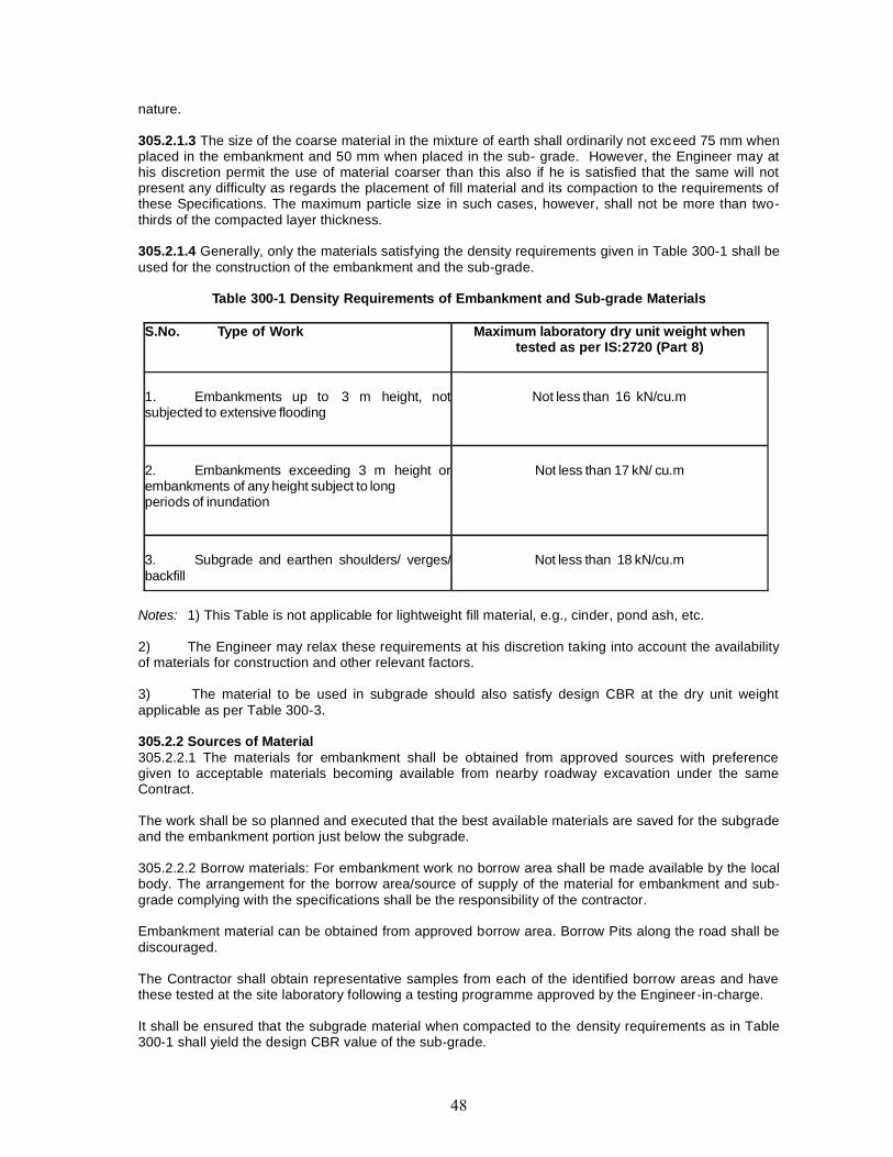
nature.
305.2.1.3 The size of the coarse material in the mixture of earth shall ordinarily not exceed 75 mm whenplaced in the embankment and 50 mm when placed in the sub- grade. However, the Engineer may athis discretion permit the use of material coarser than this also if he is satisfied that the same will notpresent any difficulty as regards the placement of fill material and its compaction to the requirements ofthese Specifications. The maximum particle size in such cases, however, shall not be more than two-thirds of the compacted layer thickness.
305.2.1.4 Generally, only the materials satisfying the density requirements given in Table 300-1 shall beused for the construction of the embankment and the sub-grade.
Table 300-1 Density Requirements of Embankment and Sub-grade Materials
S.No. Type of Work Maximum laboratory dry unit weight whentested as per IS:2720 (Part 8)
1. Embankments up to 3 m height, notsubjected to extensive flooding
Not less than 16 kN/cu.m
2. Embankments exceeding 3 m height orembankments of any height subject to longperiods of inundation
Not less than 17 kN/ cu.m
3. Subgrade and earthen shoulders/ verges/backfill
Not less than 18 kN/cu.m
Notes: 1) This Table is not applicable for lightweight fill material, e.g., cinder, pond ash, etc.
2) The Engineer may relax these requirements at his discretion taking into account the availabilityof materials for construction and other relevant factors.
3) The material to be used in subgrade should also satisfy design CBR at the dry unit weightapplicable as per Table 300-3.
305.2.2 Sources of Material305.2.2.1 The materials for embankment shall be obtained from approved sources with preferencegiven to acceptable materials becoming available from nearby roadway excavation under the sameContract.
The work shall be so planned and executed that the best available materials are saved for the subgradeand the embankment portion just below the subgrade.
305.2.2.2 Borrow materials: For embankment work no borrow area shall be made available by the localbody. The arrangement for the borrow area/source of supply of the material for embankment and sub-grade complying with the specifications shall be the responsibility of the contractor.
Embankment material can be obtained from approved borrow area. Borrow Pits along the road shall bediscouraged.
The Contractor shall obtain representative samples from each of the identified borrow areas and havethese tested at the site laboratory following a testing programme approved by the Engineer-in-charge.
It shall be ensured that the subgrade material when compacted to the density requirements as in Table300-1 shall yield the design CBR value of the sub-grade.
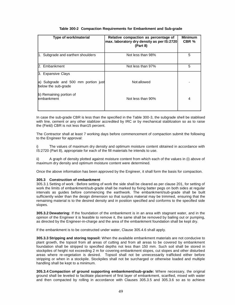
Table 300-2 Compaction Requirements for Embankment and Sub-grade
Type of work/material Relative compaction as percentage ofmax. laboratory dry density as per IS:2720
(Part 8)
MinimumCBR %
1. Subgrade and earthen shoulders Not less than 98% 5
2. Embankment Not less than 97% 5
3. Expansive Clays
a) Subgrade and 500 mm portion justbelow the sub-grade
b) Remaining portion ofembankment
Not allowed
Not less than 90%
-
4
In case the sub-grade CBR is less than the specified in the Table 300-3, the subgrade shell be stablisedwith line, cement or any other stablizer accredited by IRC or by mechanical stablization so as to raisethe (Field) CBR is not less than15 percent.
The Contractor shall at least 7 working days before commencement of compaction submit the followingto the Engineer for approval:
i) The values of maximum dry density and optimum moisture content obtained in accordance withIS:2720 (Part 8), appropriate for each of the fill materials he intends to use.
ii) A graph of density plotted against moisture content from which each of the values in (i) above ofmaximum dry density and optimum moisture content were determined.
Once the above information has been approved by the Engineer, it shall form the basis for compaction.
305.3 Construction of embankment305.3.1 Setting of work : Before setting of work the side shall be cleared as per clause 201, for setting ofwork the limits of embankment/sub-grade shall be marked by fixing batter pegs on both sides at regularintervals as guides before commencing the earthwork. The embankment/sub-grade shall be builtsufficiently wider than the design dimension so that surplus material may be trimmed, ensuring that theremaining material is to the desired density and in position specified and conforms to the specified sideslopes.
305.3.2 Dewatering: If the foundation of the embankment is in an area with stagnant water, and in theopinion of the Engineer it is feasible to remove it, the same shall be removed by bailing out or pumping,as directed by the Engineer-in-charge and the area of the embankment foundation shall be kept dry.
If the embankment is to be constructed under water, Clause 305.4.6 shall apply.
305.3.3 Stripping and storing topsoil: When the available embankment materials are not conducive toplant growth, the topsoil from all areas of cutting and from all areas to be covered by embankmentfoundation shall be stripped to specified depths not less than 150 mm. Such soil shall be stored instockpiles of height not exceeding 2 m for covering embankment slopes, cut slopes and other disturbedareas where re-vegetation is desired. Topsoil shall not be unnecessarily trafficked either beforestripping or when in a stockpile. Stockpiles shall not be surcharged or otherwise loaded and multiplehandling shall be kept to a minimum.
305.3.4 Compaction of ground supporting embankment/sub-grade: Where necessary, the originalground shall be leveled to facilitate placement of first layer of embankment, scarified, mixed with waterand then compacted by rolling in accordance with Clauses 305.3.5 and 305.3.6 so as to achieve

minimum dry density as given in Table 300-3.
In case where the difference between the sub-grade level (top of the sub-grade on which pavementrests) and ground level is less than 0.5 m and the ground does not have 98 percent relative compactionwith respect to the dry density (as given in Table 300-3), the ground shall be loosened upto a level 0.5m below the sub-grade level, watered and compacted in layers in accordance with Clauses 305.3.5 and305.3.6 to achieve dry density not less than 98 percent relative compaction as given in Table 300-3.Where so directed by the Engineer, any unsuitable material occurring in the embankment foundation(500 mm portion just below the sub-grade) shall be removed, suitably disposed and replaced byapproved materials laid in layers to the required degree of compaction.
305.3.5 Spreading material in layers and bringing to appropriate moisture content305.3.5.1 In construction of embankment/ sub-grade the construction material shall be spread in layersof uniform thickness not exceeding 200 mm compacted thickness over the entire width of embankmentby mechanical means, finished by a motor grader. It shall be compacted as per Clause 305.3.6.Successive layers shall not be placed until the layer under construction has been thoroughly compactedto the specified requirements as in Table 300-3 and got approved by the Engineer-in-charge. Eachcompacted layer shall be finished parallel to the final cross-section of the embankment.
305.3.5.2 Prior to commencement of compaction the Moisture content of the material shall be checkedat the site of placement as per IS 2720 Part-2 if found to be out of specified limits, the same shall bemade good. Where water is required to be added in such constructions, water shall be sprinkled by awater tanker fitted with sprinkler. The water shall be added uniformly and thoroughly mixed in soil byblading, harrowing until a uniform moisture content is obtained throughout the depth of the layer.
If the moisture content found more than specified limit than it shall be dried by aeration and exposure tothe sun, till the moisture content is acceptable for compaction. Compaction work shall be suspended tillthe moisture is accepted for compaction.
Moisture content of each layer of soil shall be checked in accordance with IS: 2720 (Part 2), and unlessotherwise mentioned, shall be so adjusted, making due allowance for evaporation losses, that at thetime of compaction it is in the range of 1 percent above to 2 percent below the optimum moisturecontent determined in accordance with IS: 2720 (Part 8) as the case may be. Expansive clays shall,however, be compacted at moisture content corresponding to the specified dry density, but on the wetside of the optimum moisture content obtained from the laboratory compaction curve.
Clods or hard lumps of earth shall be broken to have a maximum size of 75 mm when being placed in theembankment and a maximum size of 50 mm when being placed in the sub-grade.
305.3.6 Compaction: The compaction equipment of suitable size & capacity as approved by theEngineer-in-charge shall be employed to compaction work. The compaction equipment are static threewheel roller, self propelled single drum vibratory roller, vibratory tandem roller, pneumatic tyred, pad footrollers, etc. The compaction equipments may be used either individually or in suitable combinations.
The Contractor shall demonstrate the efficacy of the equipment he intends to use by carrying outcompaction trials. The procedure to be adopted for these site trials shall first be submitted to theEngineer-in-charge for approval.
Each layer of the material shall be thoroughly compacted to the densities specified in Table 300-3.Subsequent layers shall be placed only after the finished layer has been tested according to Clause903.2.2 and accepted by the Engineer-in-charge.
If density measurements shows reveal any soft areas in the embankment /sub-grade/earthen shouldersthan, further compaction shall be carried out as directed by the Engineer. If inspite of that the specifiedcompaction is not achieved, the material in the soft areas shall be removed and replaced by approvedmaterial & than compacted using appropriate compactor such as light weight vibratory roller, doubledrum walk behind roller, vibratory plate compactor, trench compactor or vibratory tamper to the densityrequirements and satisfaction of the Engineer-in-charge.
305.3.7 Drainage: The surface of the embankment/sub-grade at all times during construction shall be
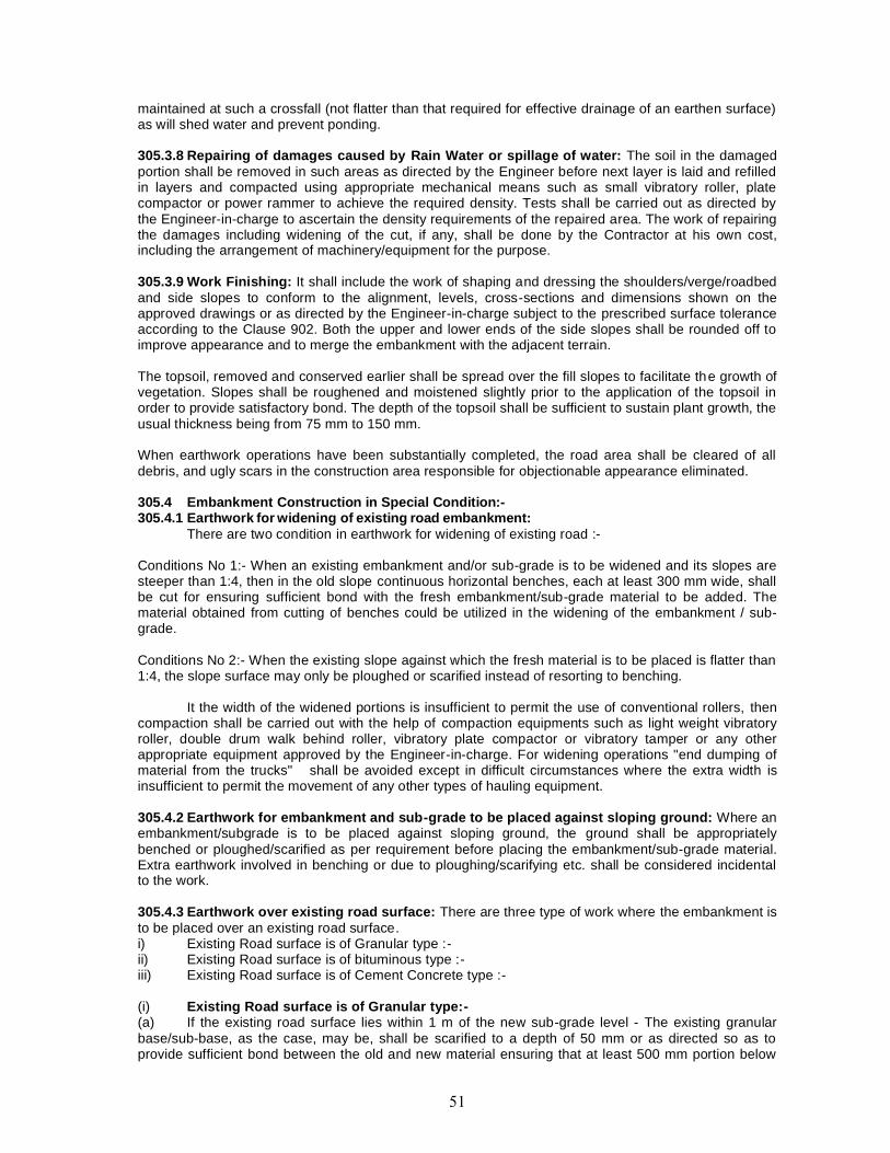
maintained at such a crossfall (not flatter than that required for effective drainage of an earthen surface)as will shed water and prevent ponding.
305.3.8 Repairing of damages caused by Rain Water or spillage of water: The soil in the damagedportion shall be removed in such areas as directed by the Engineer before next layer is laid and refilledin layers and compacted using appropriate mechanical means such as small vibratory roller, platecompactor or power rammer to achieve the required density. Tests shall be carried out as directed bythe Engineer-in-charge to ascertain the density requirements of the repaired area. The work of repairingthe damages including widening of the cut, if any, shall be done by the Contractor at his own cost,including the arrangement of machinery/equipment for the purpose.
305.3.9 Work Finishing: It shall include the work of shaping and dressing the shoulders/verge/roadbedand side slopes to conform to the alignment, levels, cross-sections and dimensions shown on theapproved drawings or as directed by the Engineer-in-charge subject to the prescribed surface toleranceaccording to the Clause 902. Both the upper and lower ends of the side slopes shall be rounded off toimprove appearance and to merge the embankment with the adjacent terrain.
The topsoil, removed and conserved earlier shall be spread over the fill slopes to facilitate the growth ofvegetation. Slopes shall be roughened and moistened slightly prior to the application of the topsoil inorder to provide satisfactory bond. The depth of the topsoil shall be sufficient to sustain plant growth, theusual thickness being from 75 mm to 150 mm.
When earthwork operations have been substantially completed, the road area shall be cleared of alldebris, and ugly scars in the construction area responsible for objectionable appearance eliminated.
305.4 Embankment Construction in Special Condition:-305.4.1 Earthwork for widening of existing road embankment:
There are two condition in earthwork for widening of existing road :-
Conditions No 1:- When an existing embankment and/or sub-grade is to be widened and its slopes aresteeper than 1:4, then in the old slope continuous horizontal benches, each at least 300 mm wide, shallbe cut for ensuring sufficient bond with the fresh embankment/sub-grade material to be added. Thematerial obtained from cutting of benches could be utilized in the widening of the embankment / sub-grade.
Conditions No 2:- When the existing slope against which the fresh material is to be placed is flatter than1:4, the slope surface may only be ploughed or scarified instead of resorting to benching.
It the width of the widened portions is insufficient to permit the use of conventional rollers, thencompaction shall be carried out with the help of compaction equipments such as light weight vibratoryroller, double drum walk behind roller, vibratory plate compactor or vibratory tamper or any otherappropriate equipment approved by the Engineer-in-charge. For widening operations "end dumping ofmaterial from the trucks" shall be avoided except in difficult circumstances where the extra width isinsufficient to permit the movement of any other types of hauling equipment.
305.4.2 Earthwork for embankment and sub-grade to be placed against sloping ground: Where anembankment/subgrade is to be placed against sloping ground, the ground shall be appropriatelybenched or ploughed/scarified as per requirement before placing the embankment/sub-grade material.Extra earthwork involved in benching or due to ploughing/scarifying etc. shall be considered incidentalto the work.
305.4.3 Earthwork over existing road surface: There are three type of work where the embankment isto be placed over an existing road surface.i) Existing Road surface is of Granular type :-ii) Existing Road surface is of bituminous type :-iii) Existing Road surface is of Cement Concrete type :-
(i) Existing Road surface is of Granular type:-(a) If the existing road surface lies within 1 m of the new sub-grade level - The existing granularbase/sub-base, as the case, may be, shall be scarified to a depth of 50 mm or as directed so as toprovide sufficient bond between the old and new material ensuring that at least 500 mm portion below
the top of new sub-grade level is compacted to the desired density;
(b) If the level difference between the existing road surface and the new formation level is morethan 1 m- The existing surface shall be permitted to stay in place without any modification.ii) Existing Road surface is of bituminous type :-(a) If the existing road surface is of bituminous type and lies within 1 m of the new sub-grade level -The bituminous layer shall be removed completely, so as to avoid presence of impermeable layerbeneath the new thin earthen layer and also provide ample bond between the old and new materialensuring that at least 500 mm portion below the top of new sub grade level is compacted to the desireddensity;
(b) If the level difference between the existing road surface and the new formation level is morethan 1 m- The existing surface shall be permitted to stay in place without any modification.
iii) Existing Road surface is of Cement Concrete type :-(a) If the existing road surface is of cement concrete type and lies within 1 m of the new sub-gradelevel, the same shall be removed completely;
305.4.4Embankment Around Structures(i) To avoid interference with the construction of abutments, wing walls or return watts ofculvert/bridge structure, the contractor shall at points to be determined by the Engineer-in-Chargesuspend work on embankments forming approaches to such structures, until such time as theconstruction of the latter of sufficiently advanced to permit the completion of approaches without the riskof interference of damage to the bridge works.
(ii) Unless directed otherwise, the filling around culverts, bridges and other structures upto adistance of twice the height of the embankment shall not be done. The fill material shall not be placedagainst any abutment or wing wall unless permission has been given by the Engineer-in-Charge but inany case not until the concrete or masonry has been in position for 14 days. The embankment shall bebrought up simultaneously in equal layers on each side of the structure to avoid displacement andunequal pressure. The sequence of work in this regard shall be got approved from the Engineer-in-Charge.
(iii) Where the provision of any filter medium is specified behind the abutment, the same shall belaid in layers simultaneously with the laying of fill material. The material used for filter material shallconform to the requirements for filter medium as specified. Payment for providing filter material shall bemade separately under relevant items.
(iv) Where it may be impracticable to use power roller or other heavy equipment, compaction shallbe carried out by mechanical tempers or other methods approved by the Engineer-in-charge. Care shallbe taken to see that the compaction equipments does not hit or come too close to any structuralmember so as to cause any damage to it.
305.4.8. Settlement period: Where settlement period is specified in the Contract, the embankmentshall remain in place for the required settlement period before excavating for abutment, wing wall,retaining wall, footings, etc., or driving foundation piles. The duration of the required settlement period ateach location shall be as provided for in the Contract or as directed by the Engineer-n-charge.
305.5 Plying of TrafficConstruction and other vehicular traffic shall not use the prepared surface of the embankment and/orsub-grade without the prior permission of the Engineer-in-charge. Any damage arising out of such useshall, however, be made good by the Contractor at his own cost as directed by the Engineer-in-charge
305.6 Quality Control, Sub-grade Strength of Work, Surface Finish & Surface Regularity.(a) The material used in embankment, sub-grade, shoulders, etc. shall be soil, moorum, gravel, amixture of these or other material approved by the Engineer. It shall be free from logs, stumps, roots,rubbish, etc.
(b) The size of coarse material shall not ordinarily exceed 75mm when placed in embankment and50mm when placed in sub-grade.
(c) Only the materials satisfying the density requirements given in Table 300.2 should be used forthe embankment.
(d) Compaction shall be as per table 300.3.
(e) The quality of materials and work shall be exercise in accordance with clause 903.
305.6.1 Surface Finish :-The permitted tolerance in surface level for sub-grade will be +20mm and (-) 25 mm.
305.6.2 Surface Regularity :-The maximum allowable difference between the road surface and underside of a 3m straight edge shallbe 20 mm for the longitudinal profile and 15mm for the cross profile.
305.7 Sub-grade Strength305.7.1 It shall be ensured prior to actual execution that the borrow area material to be used in the sub-grade satisfies the requirements of design CBR.
305.7.2 Sub-grade shall be compacted and finished to the design strength consistent with other physicalrequirements. The actual laboratory CBR values of constructed sub- grade shall be determined onundisturbed samples cut out from the compacted sub-grade in CBR mould fitted with cutting shoe or onremoulded samples, compacted to the field density at the field moisture content.
305.8 Measurements for Payment(a) Each embankment/sub-grade construction shall be measured separately by taking crosssections at intervals in the original position before the work starts and after its completion as detailedbelow.
(b) Levels shall be taken before and after construction, at grid or points 10 m centre to centrelongitudinally in straight reaches but 5 m at curves. Normally, on two-lane roads, the levels shall betaken at four positions transversely, at 0.75 and 2.75 m from either edge of the carriageway; and onsingle lane roads, these shall be taken at two positions transversely, being at 1.25 m from either edge ofthe carriageway. For multi-lane roads, levels shall be taken at two positions transversely for each laneat locations specified by the Engineer. Suitable references for the transverse grid lines should be left inthe form of embedded bricks on either ends or by other means so that it is possible to locate the gridpoints for level measurements after each successive course in laid.
(c) The computation of volumes for earthwork in cubic metres by the method of average end areasshall be done.
(d) The measurement of fill material from borrow areas shall be the difference between the netquantities of compacted fill and the net quantities of suitable material brought from roadway anddrainage excavation. For this purpose, it shall be assumed that one cu.m of suitable material brought tosite from road and drainage excavation forms one cu.m of compacted fill and all bulking or shrinkageshall be ignored.
(e) Construction of high embankment with specified material and in specified manner shall bemeasured in cu.m.
(f) Stripping including storing and reapplication of top soil shall be measured in cu.m.
(g) Work involving loosening and recompacting of ground supporting embankment /subgrade shallbe measured in cu.m.
(h) Removal of unsuitable material at embankment/sub-grade foundation and replacement withsuitable material shall be measured in cu.m.
(i) Scarifying existing granular/bituminous road surface shall be measured in square metres.Dismantling and removal of existing cement concrete pavement shall be measured vide Clause 202.6.
(j) Filter medium and backfill material behind abutments, wing walls and other retaining structuresshall be measured as finished work in position in cu.m.
305.9 Rates305.9.1 The Contract unit rates for the items of embankment and sub-grade construction shall bepayment in full for carrying out the required operations including full compensation for:
i) Cost of arrangement of land as a source of supply of material of required quantity forconstruction unless provided otherwise in the Contract;
ii) Setting out;
iii) Compacting ground supporting embankment/sub-grade except where removal and replacementof suitable material or loosening and recompacting is involved;
iv) Scarifying or cutting continuous horizontal benches 300 mm wide on side slopes of existingembankment and sub-grade as applicable;
v) Cost of watering or drying of material in borrow areas and/or embankment and sub-grade duringconstruction as required;
vi) Spreading in layers, bringing to appropriate moisture and compacting to Specificationrequirements;
vii) Shaping and dressing top and slopes of the embankment and sub- grade including rounding ofcorners;
viii) Restricted working at sites of structures;
ix) Working on narrow width of embankment and sub-grade;
x) Excavation in all soils from borrow pits/designated borrow areas including clearing and grubbingand transporting the material to embankment and sub-grade site with all lifts and leads unlessotherwise provided for in the Contract;
xi) All labour, materials, tools, equipment and incidentals necessary to complete the work to theSpecifications;
xii) Dewatering; and
xiii) Keeping the embankment/completed formation free of water.
305.9.5 The Contract unit rate for scarifying existing granular/bituminous road surface shall be paymentin full for carrying out the required operations including full compensation for all labour, materials, tools,equipment and incidentals, necessary to complete the work. This will also comprise of handling, givingcredit towards salvage value and disposal of the dismantled materials with all leads and lifts or asotherwise specified.
305.9.7 The Contract unit rate for providing and laying filter material behind abutments shall be paymentin full for carrying out the required operations including all materials, labour, tools, equipment andincidentals to complete the work to Specifications.
305.9.8 Summary of Sub-grade & Embankment Construction.
1 Obtain materials (soil) for embankment from approved sources.
2 After clearing the site, mark the limits of embankment by fixing batter pegs and marking toelines on both sides at regular intervals as guides. The embankment shall be built sufficiently wider(about 300 mm on either side of Roadway) than the specified formation width so that surplus materialat the edges may be trimmed to ensure proper compaction of the edges and side slopes.
3 Remove stagnant water, if any, from the foundation of the embankment.

4 Where the available embankment materials (Soil) are not conducive to plant growth, topsoilfrom areas of cutting and areas to be covered by embankment should be stripped to specified depthnot exceeding 150 mm and stored for covering slopes, and other disturbed areas where re-vegetationis required.
5. If the granular 1 m of the new sub-grade level, the same should be scarified to a depth of atleast 50 mm for achieving bond between old and new material.
6. If the existing surface is of cement concrete type and lies within 1 m of the new sub-gradelevel, the same shall be removed completely.
7. The size of the coarse material in the mixture of earth used for embankment constructionshould ordinarily not exceed 75 mm.
8 The soil should be spread over the entire width of the embankment in layers not exceeding 200mm compacted thickness. The clods should be broken to less than 75 mm size & 50 mm for sub grade.
9. Expensive clay exhibiting swell & shrinkage properties shall not be used as fill material.
10 Each layer of sub grade & soulder should be compacted to at least 98 percent andembankment 97% of the Standard Proctor Density.
11. Ensure that longitudinal and cross profiles should be in conformity with the approved drawings.
12. Approval of the site Engineer should be obtained for each finished layer. Subsequent layersshall be placed only after the finished layer has been tested and accepted by site Engineer. (Such anapproval would require surface level and compaction control tests).
13 When an existing embankment and/ or sub-grade is to be widened and its slopes are steeperthan 1 vertical to 4 horizontal, continuous horizontal benches, each at least 300 mm wide, should becut into the old slope for ensuring adequate bond with the fresh embankment/ sub-grade material to beadded.
14 When the width of the widened portions is insufficient to permit the use of conventionalrollers, compaction shall be carried out with the help of small vibratory rollers/ plate compacters/power rammers or any other equipment approved by the Engineer.
15 The filling around culverts and bridges, for forming approaches up to a distance of twicethe height of the road from the back of abutment should be done with granular materials andshould not be placed until the concrete or masonry has been in position for 14 days. Approvalfor the sequence of work and equipment should be obtained from the Engineer-in-charge beforetaking up the work.
16. Control Tests & FrequencyTest Frequency (min.)
Gradation One test per 200 m3
Atterberg limits One test per 200 m3
Moisture content prior to compaction One test per 250 m3
Density of compacted layer One test per 500 m3
Deleterious constituentsAs required
C.B.R. As required
17. Discourage borrow pits along the road; where permitted, ridges of minimum 8 mwidth should be left at intervals not exceeding 300 m. Small drains should be cut through theridges to facilitate drainage.
The depth of borrow pits should be so regulated that their bottom does not cut an imaginaryline having a slope of 1 vertical to 4 horizontal projected from the edge of the final section of thebank, the maximum depth in any case being limited to 1.0 m.
18. Do maintain a camber/ cross fall of 4 percent during construction for effective drainage
and prevention of ponding of water.
19. The area of the embankment foundation should be kept dry. Test the material (soil)for its suitability for use in the embankment at least seven days before commencement ofearthwork. Tests should include soil. classification test data and data regarding maximum drydensity, OMC, and CBR (soaked and unsoaked).
20. For widening of existing embankment start earth work from toe line.
21. Do not allow borrow pits within a distance equal to the height of the embankmentsubject to a minimum of 1.5 m from the toe of the road embankment.
22. Do not allow construction or other vehicular traffic over the prepared surface ofembankment/ sub-grade.
23. Do not allow dumping of earth from top to widen an existing embankment.
306. SOIL EROSION AND SEDIMENTATION CONTROL.306.1 General
This work shall consist of measures as shown on plans or as directed by the Engineer-in-chargeto control soil erosion, sedimentation and water pollution, through use of berms, dikes, sediment basins,fibre mats, mulches, grasses, slope drains, and other devices.
306.2 MaterialsAll materials shall meet commercial grade standards and shall be approved by the Engineer-in-
charge before being used in the work.
306.3 Construction OperationsWork shall not be started until the erosion/ sedimentation control schedules and methods of
operations for the applicable construction have been approved by the Engineer-in-charge. For abovethe contractor shall submit to the Engineer-in-Charge for approval his schedules of work. He shall alsosubmit for approval his proposed method of erosion/sedimentation control.
307. TURFING WITH SODS307.1 General
This work shall consist of furnishing and laying of the live sod of perennial turf forming grass onembankment slopes, verges (earthen shoulders) or other locations shown on the drawings or asdirected by the Engineer-in-charge. Unless otherwise specified, the work shall be taken up as soon aspossible following construction of the embankment, provided the season is favourable for establishmentof the sod.
308 SEEDING AND MULCHING308.1 General
This shall consist of preparing slopes, placing topsoil, furnishing all seeds, commercial or organicfertilizers and mulching materials, providing jute netting and placing and incorporating the same onembankment slopes or other locations designated by the Engineer-in-charge or shown in the Contractdocuments.
309 SURFACE/SUB-SURFACE DRAINS309.1 General
The work shall consist of constructing surface and/or sub-surface drains in accordance with therequirements of these Specifications and to the lines, grades, dimensions and other particulars shownon the drawings or as directed by the Engineer-in-charge. Schedule of work shall be so arranged thatthe drains are completed in proper sequence with road works to ensure that no excavation of thecompleted road works is necessary subsequently or any damage is caused to these works due to lack
85 85
of drainage.
309.2 Surface DrainsSurface drains shall be excavated to the specified lines, grades, levels and dimensions to the
requirements of Clause 301. The excavated material shall be removed from the area adjoining thedrains and if found suitable, utilized in embankment/sub-grade construction. All unsuitable material shallbe disposed of as directed.
The excavated bed and sides of the drains shall be dressed to bring these in close conformitywith the specified dimensions, levels and slopes.
Where so indicated, drains shall be lined or turfed with suitable materials in accordance withdetails shown on the drawings.
All works on drain construction shall be planned and executed in proper sequence with otherworks as approved by the Engineer, with a view to ensuring adequate drainage for the area andminimizing erosion/sedimentation.
309.3 Sub-Surface Drains
309.3.1 Scope : Sub-surface drains shall be of close-jointed perforated pipes, open- jointedunperforated pipes, surrounded by granular material laid in a trench or aggregatedrains to drain thepavement courses. Sub-surface drains designed using Geosynthetics and approved by the Engineer-in-charge can also be used.
309.3.2 MaterialsA. Pipe: Perforated pipes for the drains may be metal/asbestos cement/cement concrete/PVC andunperforated pipes of vitrified clay/ cement concrete/asbestos cement. The type, size and grade of thepipe to be used shall be as specified in the Contract. In no case, however, shall the internal diameter ofthe pipe be less than 100 mm. Holes for perforated pipes shall be on one half of the circumference onlyand conform to the spacing indicated on the drawings. Size of the holes shall not ordinarily be greaterthan half of size of the material surrounding the pipe, subject to being minimum 3 mm and maximum 6mm. D stands for the size of the sieve that allows 85 percent of the material to pass through it.
B. Backfill material: Backfill material shall consist of sound, tough, hard, durable particles of freedraining sand-gravel material or crushed stone and shall be free of organic material, clay balls or otherdeleterious matter. Unless the Contract specified any particular gradings for the backfill material orrequires these to be designed on inverted filter criteria for filtration and permeability to the approval ofthe Engineer-in-charge, the backfill material shall be provided on the following lines:
i) Where the soil met with in the trench is of fine grained type (e.g., silt, clay or a mixturethereof), the backfill material shall conform to Class I grading set out in-Table 300-4;
ii) Where the soil met with in the trench is of coarse silt to medium sand or sandy type, thebackfill material shall correspond to Class II grading of Table 300-4; and
iii) Where soil met with in the trench is gravelly sand, the backfill material shall correspondto Class III grading of Table 300-4.
Thickness of backfill material around the pipe shall be as shown on the drawings subject tobeing at least 150 mm alround in all cases.
Geosynthetics for use with subsurface drain shall conform to the requirements as per Section700.
309.3.3 Trench excavation: Trench for sub-surface drain shall be excavated to the specified lines,grades and dimensions shown in the drawings provided that width of trench at pipe level shall not beless than 450 mm. The excavation shall begin at the outlet end of the drain and proceed towards theupper end. Where unsuitable material is met with at the trench bed, the same shall be removed to suchdepth as directed by the Engineer-in-charge and backfilled with approved material which shall bethoroughly compacted to the specified degree.
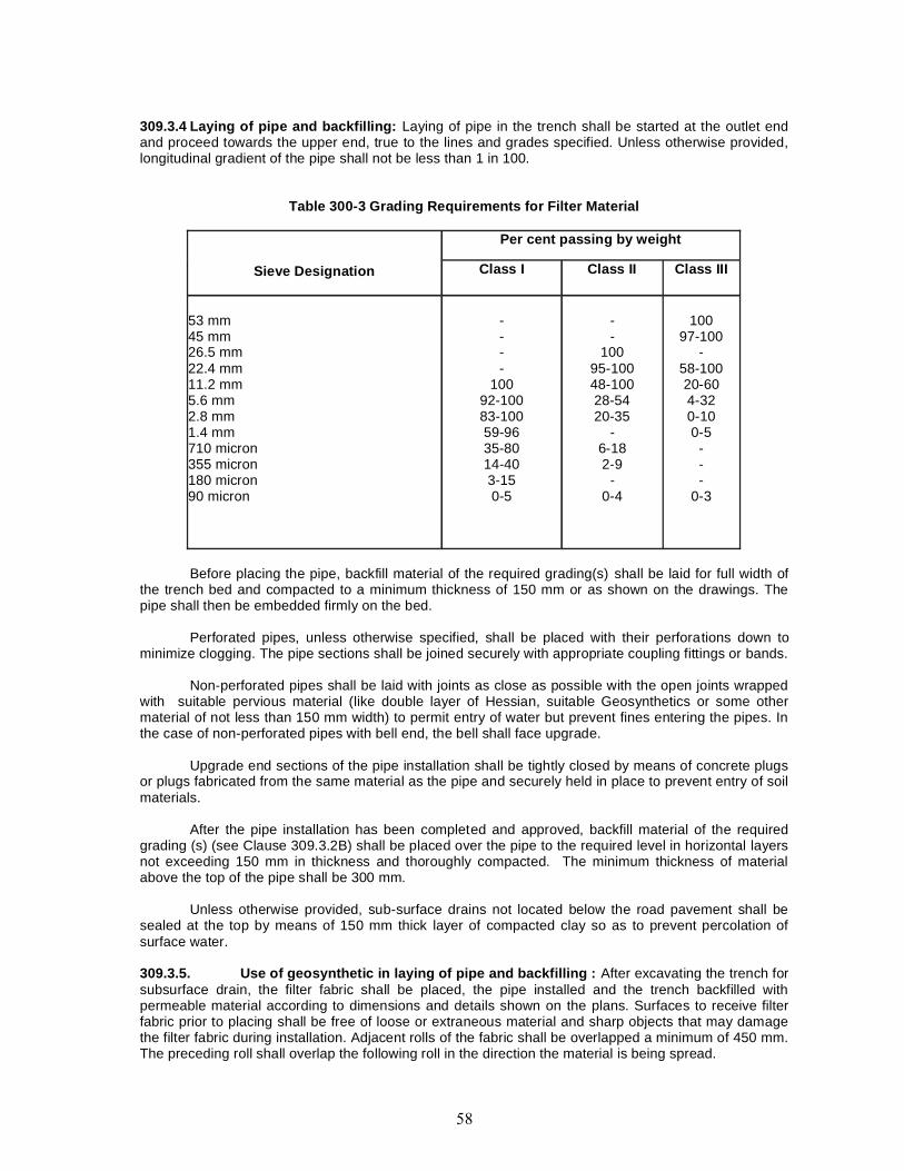
309.3.4 Laying of pipe and backfilling: Laying of pipe in the trench shall be started at the outlet endand proceed towards the upper end, true to the lines and grades specified. Unless otherwise provided,longitudinal gradient of the pipe shall not be less than 1 in 100.
Table 300-3 Grading Requirements for Filter Material
Sieve Designation
Per cent passing by weight
Class I Class II Class III
53 mm45 mm26.5 mm22.4 mm11.2 mm5.6 mm2.8 mm1.4 mm710 micron355 micron180 micron90 micron
----
10092-10083-10059-9635-8014-403-150-5
--
10095-10048-10028-5420-35
-6-182-9
-0-4
10097-100
-58-10020-604-320-100-5
---
0-3
Before placing the pipe, backfill material of the required grading(s) shall be laid for full width ofthe trench bed and compacted to a minimum thickness of 150 mm or as shown on the drawings. Thepipe shall then be embedded firmly on the bed.
Perforated pipes, unless otherwise specified, shall be placed with their perforations down tominimize clogging. The pipe sections shall be joined securely with appropriate coupling fittings or bands.
Non-perforated pipes shall be laid with joints as close as possible with the open joints wrappedwith suitable pervious material (like double layer of Hessian, suitable Geosynthetics or some othermaterial of not less than 150 mm width) to permit entry of water but prevent fines entering the pipes. Inthe case of non-perforated pipes with bell end, the bell shall face upgrade.
Upgrade end sections of the pipe installation shall be tightly closed by means of concrete plugsor plugs fabricated from the same material as the pipe and securely held in place to prevent entry of soilmaterials.
After the pipe installation has been completed and approved, backfill material of the requiredgrading (s) (see Clause 309.3.2B) shall be placed over the pipe to the required level in horizontal layersnot exceeding 150 mm in thickness and thoroughly compacted. The minimum thickness of materialabove the top of the pipe shall be 300 mm.
Unless otherwise provided, sub-surface drains not located below the road pavement shall besealed at the top by means of 150 mm thick layer of compacted clay so as to prevent percolation ofsurface water.
309.3.5. Use of geosynthetic in laying of pipe and backfilling : After excavating the trench forsubsurface drain, the filter fabric shall be placed, the pipe installed and the trench backfilled withpermeable material according to dimensions and details shown on the plans. Surfaces to receive filterfabric prior to placing shall be free of loose or extraneous material and sharp objects that may damagethe filter fabric during installation. Adjacent rolls of the fabric shall be overlapped a minimum of 450 mm.The preceding roll shall overlap the following roll in the direction the material is being spread.
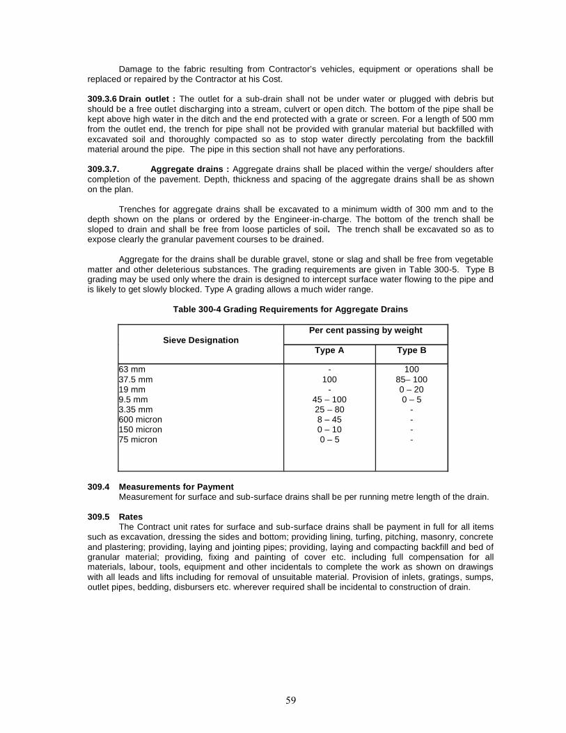
Damage to the fabric resulting from Contractor’s vehicles, equipment or operations shall bereplaced or repaired by the Contractor at his Cost.
309.3.6 Drain outlet : The outlet for a sub-drain shall not be under water or plugged with debris butshould be a free outlet discharging into a stream, culvert or open ditch. The bottom of the pipe shall bekept above high water in the ditch and the end protected with a grate or screen. For a length of 500 mmfrom the outlet end, the trench for pipe shall not be provided with granular material but backfilled withexcavated soil and thoroughly compacted so as to stop water directly percolating from the backfillmaterial around the pipe. The pipe in this section shall not have any perforations.
309.3.7. Aggregate drains : Aggregate drains shall be placed within the verge/ shoulders aftercompletion of the pavement. Depth, thickness and spacing of the aggregate drains shall be as shownon the plan.
Trenches for aggregate drains shall be excavated to a minimum width of 300 mm and to thedepth shown on the plans or ordered by the Engineer-in-charge. The bottom of the trench shall besloped to drain and shall be free from loose particles of soil. The trench shall be excavated so as toexpose clearly the granular pavement courses to be drained.
Aggregate for the drains shall be durable gravel, stone or slag and shall be free from vegetablematter and other deleterious substances. The grading requirements are given in Table 300-5. Type Bgrading may be used only where the drain is designed to intercept surface water flowing to the pipe andis likely to get slowly blocked. Type A grading allows a much wider range.
Table 300-4 Grading Requirements for Aggregate Drains
Sieve DesignationPer cent passing by weight
Type A Type B
63 mm37.5 mm19 mm9.5 mm3.35 mm600 micron150 micron75 micron
-100
-45 – 10025 – 808 – 450 – 100 – 5
10085– 1000 – 200 – 5
----
309.4 Measurements for PaymentMeasurement for surface and sub-surface drains shall be per running metre length of the drain.
309.5 RatesThe Contract unit rates for surface and sub-surface drains shall be payment in full for all items
such as excavation, dressing the sides and bottom; providing lining, turfing, pitching, masonry, concreteand plastering; providing, laying and jointing pipes; providing, laying and compacting backfill and bed ofgranular material; providing, fixing and painting of cover etc. including full compensation for allmaterials, labour, tools, equipment and other incidentals to complete the work as shown on drawingswith all leads and lifts including for removal of unsuitable material. Provision of inlets, gratings, sumps,outlet pipes, bedding, disbursers etc. wherever required shall be incidental to construction of drain.
400. SUB-BASES, BASES (NON-BITUMINIOUS)
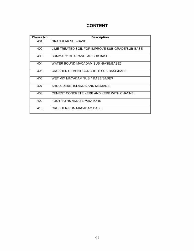
CONTENT
Clause No Description401 GRANULAR SUB-BASE
402 LIME TREATED SOIL FOR IMPROVE SUB-GRADE/SUB-BASE
403 SUMMARY OF GRANULAR SUB BASE.
404 WATER BOUND MACADAM SUB -BASE/BASE5
405 CRUSHED CEMENT CONCRETE SUB-BASE/BASE.
406 WET MIX MACADAM SUB 4 BASE/BASES
407 SHOULDERS, ISLANDS AND MEDIANS
408 CEMENT CONCRETE KERB AND KERB WITH CHANNEL
409 FOOTPATHS AND SEPARATORS
410 CRUSHER-RUN MACADAM BASE
401. GRANULAR SUB-BASE
401.1. General
(i) Granular sub base shall consist of laying and compacting well-graded material on previously prepared sub-grade with these Specifications.
(ii) The material shall be laid in layer or in layers as sub-base according to the requirement and according to thelines, grades and cross -sections shown on the approved drawings or as directed by the Engineer in charge.
401.2. Materials for granular sub base401.2.1.
(a) The natural sand, moorum, gravel, crushed stone, or combination thereof as required shall be used forgranular sub base.
(b) Materials like crushed slag crushed concrete, brick metal and kankar may be allowed only with the specificapproval of the Engineer in charge.
(c) The material shall be free from organic or other deleterious constituents.
(d) The granular sub base material shall be conform to one of the three grading given in Table 400-1.
401.2.2. Physical requirements of granular sub base material:
(i) The material shall have a 10% fines value of 50 kilo Newton (KN) or more when tested in compliance withBS:812 (Part 111).
(ii) The water absorption value of the coarse aggregate shall be determined as per IS: 2386 (Pan 3).
(iii) If this value is greater than 2%, the soundness test shall be carried out on the material delivered to site asper IS: 383.
(iv) For Grading II and III materials, the CBR shall be determined at the density and moisture content likely to bedeveloped in equilibrium conditions which shall be taken as being the density relating to a uniform air voidscontent of 5 %.
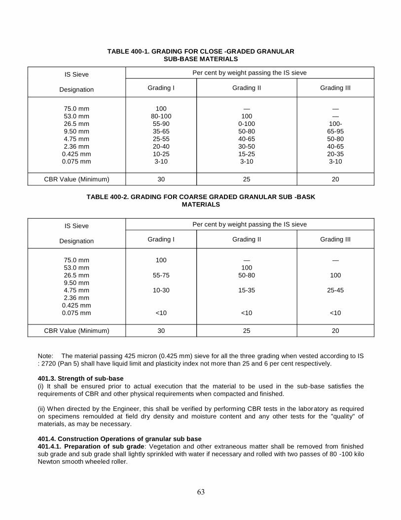
TABLE 400-1. GRADING FOR CLOSE -GRADED GRANULARSUB-BASE MATERIALS
TABLE 400-2. GRADING FOR COARSE GRADED GRANULAR SUB -BASKMATERIALS
Note: The material passing 425 micron (0.425 mm) sieve for all the three grading when vested according to IS: 2720 (Pan 5) shall have liquid limit and plasticity index not more than 25 and 6 per cent respectively.
401.3. Strength of sub-base(i) It shall be ensured prior to actual execution that the material to be used in the sub-base satisfies therequirements of CBR and other physical requirements when compacted and finished.
(ii) When directed by the Engineer, this shall be verified by performing CBR tests in the laboratory as requiredon specimens remoulded at field dry density and moisture content and any other tests for the "quality" ofmaterials, as may be necessary.
401.4. Construction Operations of granular sub base401.4.1. Preparation of sub grade: Vegetation and other extraneous matter shall be removed from finishedsub grade and sub grade shall lightly sprinkled with water if necessary and rolled with two passes of 80 -100 kiloNewton smooth wheeled roller.
IS Sieve
Designation
Per cent by weight passing the IS sieve
Grading I Grading II Grading III
75.0 mm53.0 mm26.5 mm9.50 mm4.75 mm2.36 mm
0.425 mm0.075 mm
10080-10055-9035-6525-5520-4010-253-10
—100
0-10050-8040-6530-5015-253-10
——
100-65-9550-8040-6520-353-10
CBR Value (Minimum) 30 25 20
IS Sieve
Designation
Per cent by weight passing the IS sieve
Grading I Grading II Grading III
75.0 mm53.0 mm26.5 mm9.50 mm4.75 mm2.36 mm
0.425 mm0.075 mm
100
55-75
10-30
<10
—100
50-80
15-35
<10
—
100
25-45
<10
CBR Value (Minimum) 30 25 20
401.4.2. Spreading and compacting:(i) The sub-base material of grading specified in the Contract shall be spread on the prepared sub grade withthe help of a motor grader or by other means as approved by the Engineer in charge.
(ii) When the sub-base material consists of combination of material mixing shall be done mechanically by themix-in-place method, except for small sized jobs.
(iii) Manual mixing shall be permitted only where the width of laying is not adequate for mechanical operations,as in small-sized jobs.
(iv) Moisture content of the loose material shall be checked in accordance with 15:2720 (Part 2) and suitablyadjusted by sprinkling additional water uniformly and at controlled quantities to variable widths of surface orother means approved by the Engineer in charge so that, at the time of compaction, it is from 1% above to 2%below the optimum moisture content corresponding to IS: 2720 (Part 8). While adding water, due allowanceshall be made for evaporation losses. After water has been added, the material shall be processed bymechanical or other approved means like disc harrows, rotavators until the layer is uniformly wet. Immediatelythereafter, rolling shall start.
(v) If the thickness of the compacted layer does not exceed 100 mm, a smooth wheeled roller of 80 to 100 KNweight may be used.
(vi) For a compacted single layer upto 225 mm the compaction shall be done with the help of a vibratory roller ofminimum 80 to 100 kN static weight with plain drum or pad foot- drum or heavy pneumatic tyred roller ofminimum 200 to 300 kN weight having a minimum tyre pressure of 0.7 MN/m2 or equivalent capacity rollercapable of achieving the required compaction.
(vii) Rolling shall commence at the lower edge and proceed towards the upper edge longitudinally for portionshaving unidirectional crossfall and super-elevation and shall commence at the edges and progress towards thecentre for portions having crossfall on both sides.
(viii) Each pass of the roller shall uniformly overlap not less than one- third of the track made in the precedingpass.
(ix) During rolling, the grade and crossfall (camber) shall be checked and any high spots or depressions, whichbecome apparent, corrected by removing or adding fresh material.
(x) The speed of the roller shall not exceed 5 km/ hour.
(xi) Rolling shall be continued all the density achieved is at least 98% of the maximum dry density for thematerial determined as per IS: 2720 (Part 8).
(xii) The surface of any fully compacted layer shall be well closed, free from movement of compactionequipment and ridges, cracks or loose material. All loose, segregated or otherwise defective areas shall bemade good to the full thickness of layer and re-compacted.
401.5. Surface Finish and Quality Control of Work
(i) Surface Levels: The tolerance in surface level for granular sub-base will be restricted to (+) 10 mm and (-) 20mm. A grid of 6.25 m longitudinally by 3.5 m transversely for any 10 consecutive measurements takenlongitudinally or transversely, not more than one measurement shall be permitted to exceed the tolerance asabove.
(ii) Surface Regularity: The maximum permitted difference between the sub-base and 3 m straight edge shallbe 8 mm. The cross profile should conform to the required camber.
(iii) Compaction: Density shall be 98% of maximum dry density for the material determined as per IS: 2720,Part 8.
(iv) Tests and their frequency shall be same as for granular as per clause 903.
401.6. Arrangements for Traffic
During the period of construction, arrangement of traffic shall be maintained in accordance with direction of theEngineer in charge.
401.7. Measurements for Payment
(i) Granular sub -base shall be measured as finished work in position in cubic meters.(ii) The protection of edges of granular sub-base extended over the full formation as shown in the drawing shallbe considered incidental to the work of providing granular sub-base and as such no extra payment shall bemade for the same.
401.8. Rate
The Contract unit rate for granular sub-base shall be payment in full for carrying out the required operationsincluding full compensation for:
(i) Making arrangements for traffic except for initial treatment to verges, shoulders and construction ofdiversions;(ii) Furnishing all materials to be incorporated in the work including all royalties, fees, rents where necessary andall leads and lifts;(iii) All labour, tools, equipment and incidentals to complete the work to the Specifications;(iv) Carrying out the work in pan widths of road where directed; and(v) Carrying out the required tests for quality control.
402. LIME TREATED SOIL FOR IMPROVESUB-GRADE/SUB-BASE
402.1. ScopeThis work shall consist of laying and compacting an improved sub-grade/lower sub-base of soil treated with limeon prepared sub-grade in accordance with the requirements of these Specifications and in conformity with thelines, grades and cross-sections shown on the approved drawings or as directed by the Engineer in charge.Lime treatment is generally effective for soils which contain a relative ly high percentage of clay and silly clay.
402.2. Materials402.2.1. Soil: Except when otherwise specified, the soil used for stabilization shall be the local clayey soilhaving a plasticity index greate than 8.
402.2.2. Lime: Lime for lime -soil stabilization work shall be commercial dry lime slaked at site or pre -slakedlime delivered to the site in suitable packing. Unless otherwise permitted by the Engineer in charge, the limeshall have purity of not less than 70 per cent by weight of Quick lime (CaO) when tested in accordance with IS:1514. Lime shall be properly stored to avoid prolonged exposure to the atmosphere and consequentcarbonation which would reduce its binding properties.
402.2.3. Quantity of lime in stabilized mix: Quantity of lime to be added as percentage by weight of the drysoil shall be as specified in the Contract. The quantity of lime used shall be related to its calcium oxide contentwhich shall be specified. Where the lime of different Calcium oxide content is to be used; its quantity shall besuitably adjusted to the approval of the Engineer in charge so that equivalent calcium oxide is incorporated inthe work. The mix design shall be done to arrive at the appropriate quantity of lime to be added, having due
regard to the purity of lime, the type of soil, the moisture -density relationship, and the design CBR/UnroofedCompressive Strength (UCS) value specified in the Contract. The laboratory CBR/UCS value shall be at least1.5 limes the minimum field value of CBR/UCS stipulated in the Contract. Sub-Bases, Bases (Non-Bituminous)and Shoulders
402.2.4. Water: The water to be used for lime stabilization shall be clean and free from injurious substances.Potable water shall be preferred.
402.3. Construction Operations402.3.1. Weather limitations: Lime -soil stabilization shall not be done when the air temperature in the shade isless than 10° C.
402.3.2. Degree of pulverization: For lime stabilization, the soil before addition of stabilizer shall be pulverizedusing agricultural implements like disc harrows and rotavators to the extern that it passes the requirements setout in Table 400-3 when tested in accordance with the method described in Appendix 3.
TABLE 400-3. SOIL PULVERISATION REQUIREMENTS FSTABILISATIONSTABILISATIONIS Sieve designation Minimum per cent by weight passing the IS Sieve26.5 mm 100 5.6 mm SO
402.33. Equipment for construction: Stabilized soil sub -bases shall be constructed by mix- in -place methodof construction or as otherwise approved by the Engineer in charge. Manual mixing shall be permitted onlywhere the width of laying is not adequate for mechanical operations, as in small-sized jobs. The equipment usedfor mix- in-place construction shall be a rotavaior or similar approved equipment capable of pulverizing andmixing the soil with additive and water to specified degree to the full thickness of the layer being processed, andof achieving the desired degree of mixing and uniformity of the stabilized material. If so desired by the Engineerin charge, trial runs with the equipment shall be carried out to establish its suitability for work. The thickness ofany layer to be stabilized shall be not less than 100 mm when compacted. The maximum thickness shall be 200mm, provided the plant used is accepted by the Engineer in charge.
402.3.4. Mix-in -place method of construction: Before deploying the equipment, the soil after it is made freeof undesirable vegetation or other deleterious matter shall be spread uniformly on the prepared sub grade in aquantity sufficient to achieve the desired compacted thickness of the stabilized layer. Where single-passequipment is to be employed, the soil shall be lightly rolled at the discretion of the Engineer in charge, Sub-Bases, and Bases (Non-Bituminous) and Shoulders the equipment used shall either be of single -pass ormultiple pass type. The mixers shall be equipped with an appropriate device for controlling the depth ofprocessing and the mixing blades shall be maintained or reset periodically so that the correct depth of mixing isobtained at all times. With single -pass equipment the forward speed of the machine shall be so selected inrelation to the rotor speed that the required degree of mixing, pulverization and depth of processing is obtained.In multiple pass processing, the prepared sub grade shall be pulverized to die required depth with successivepasses of the equipment and the moisture content adjusted to be within prescribed limits mentioned hereinafter.The blending or stabilizing material shall then be spread uniformly and mix continued with successive passesuntil the required depth and uniform it of processing has been obtained. The mixing equipment shall be so setthat it cuts slightly into the edge of the adjoining lane processed previously so as to ensure that all the materialforming a layer has been properly processed for the full width.
402.3.5. Construction with manual means: Where manual mixin is permitted, the soil from borrow areas shallfirst be freed of all vegetation and other deleterious matter and placed on the prepared sub grade. The soil shallthen be pulverized by means of crow-bars, pick axes or other means approved by the Engineer in charge. Waterin requisite quantities may be sprinkled on the soil for aiding pulverization. On the pulverized soil, the blendingmaterial(s) in requisite quantities shall be spread uniformly and mixed thoroughly by working with spades orother similar implements till the whole mass are uniform. After adjusting the moisture content to be within thelimits mentioned later, the mixed material shall be leveled up to the required thickness so that it is ready to berolled.
402.3.6. Addition of lime: Lime may be mixed with the prepared material either in slurry form or dry state at theoption of the Contractor with the approval of the Engineer in charge. Dry lime shall be prevented from blowingby adding water to the lime or other suitable means selected by the Contractor, with the approval o f theEngineer in charge. The tops of windrowed material may be flattened or slightly trenched to receive the lime.The distance to which lime may be spread upon Sub-Bases, Bases (Non-Bituminous) and Shoulders Section400 the prepared material ahead of the mixing operation shall be determined by the Engineer in charge. Notraffic other than the mixing equipment shall be allowed to pass over the spread lime until after completion ofmixing. Mixing or remixing operations, regardless of equipment used, shall continue until the material is free ofany white streaks or pockets of lime and the mixture is uniform. Non-uniformity of color reaction, when thetreated material is tested with the standard phenolphthalein alcohol indicator, will be considered evidence ofinadequate mixing,
402.3.7. Moisture content for compaction: The moisture content at compaction checked vide IS: 2720 (Part 2)shall neither be less than the optimum moisture content corresponding to IS: 2720 (Part 8) nor more than 2 percent above it.
402.3.8. Rolling: Immediately after spreading, grading and leveling of the mixed material, compaction shall becarried out with approved equipment preceded by a few passes of lighter rollers if necessary. Rolling shallcommence at edges and progress towards the centre, except at super elevated portions’ where it shallcommence at the inner edge and progress towards outer edge. During rolling the surface shall be frequentlychecked for grade and cross fall (camber) and any irregularities corrected by loosening the material andremoving/ adding fresh material. Compaction shall continue until the density achieved is at least 98 per cent ofthe maximum dry density for the material determined in accordance with IS: 2720 (Part 8). Care shall be takento see that the compaction of lime stabilized material is completed within three hours of its mixing or suchshorter period as may be found necessary in dry weather. During rolling it shall be ensured that roller does notbear directly on hardened or partially hardened treated material previously laid other than what may benecessary for achieving the specified compaction at the joint. The final surface shall be well closed, free frommovement under compaction planes, ridges, cracks or loose material. All loose or segregated or otherwisedefective areas shall be made good to the full thickness of the layer and recomputed.
402.3.9. Curing: The sub-base course shall be suitably cured for a minimum period of 7 days after whichsubsequent pavement courses shall be laid to prevent the surface from drying out and becoming 108 Sub-Bases, Bases (Non-Bituminous) and Shoulders Section 400 friable. No traffic of any kind shall ply over thecompleted sub -base unless permitted by the Engineer in charge.
402.4. Surface Finish and Quality Control of Work The surface finish of construction shall conform to therequirements of Clause 902. Control on the quality of materials and works shall be exercised by the Engineer incharge in accordance with Section 900. 402.5. Strength when lime is used for improving the sub grade, the soil-lime mix shall be tested for its CBR value. When lime stabilized soil is used in a sub-base, it shall be tested forunconfined compressive strength (UCS) at 7 days. In case of variation from the design CBR/UCS, in situ valuebeing lower, the pavement design shall be reviewed based on the actual CBR/UCS values. The extra pavementthickness needed on account of lower CBR/UCS value shall be constructed by the Contractor at his own cost.
402.6. Arrangements of Traffic During the period of construction, arrangement of traffic shall be maintained inaccordance with Clause 112. 402.7. Measurements for Payment Stabilized soil sub-base shall be measured asfinished work in position in cubic meters.
402.8. RatesThe Contract unit rate for lime stabilized soil sub-base shall be payment in full for carrying out the requiredoperations including full compensation for all components listed in Clause 401.8 (i) to (v).
403:- Summary of granular sub base.1. Obtain material from approved sources. The material should be natural sand, moorum, gravel and it self beconformed to grading and physical requirement as per clause 401.22.
2. Remove all vegetation and other extraneous material etc. from the sub grade already prepared, lightlysprinkle with water, if necessary, and roll with two passes of 80-100 KN road roller or any other suitablecompactor/ vibratory other?
3. The sub base material should be spread in layers not exceeding 100 mm compacted thicknesses. If suitablevibratory rollers are available, the compacted thickness of layer can be up to a maximum of 225 mm.
4. Each layer shall be uniformly spread and thoroughly compacted. Spreading and compaction shall be carriedout as per clause surface finish and quality control of work shall be as per clause 401.5.
5. Approval of the site engineer should be obtained for each layer. such an approval would require surface leveland compaction control tests.
6. PRECAUTIONS:-
1. Ensure uniform mixing of GSB material and water by mechanical means like tractor towed implements.
2. Ensure that on clayey sub grades, the percent fines passing 75 micron in the GSB material do not exceed5%.
3. Do provide aggregate plugs at the exposed edges of GSB where extended over the full formation width.
4. Look for soft patches, if any, and rectify ‘ them by removing or adding fresh material and compacting the samethoroughly.
404. WATER BOUND MACADAM SUB -BASE/BASE5404.1. Scope404.1.1. water bound macadam sub -base/base5 work shall consist of clean, crushed aggregates me chemicallyinterlocked by roiling and bonding together with screening, binding material where necessary and water laid ona properly prepared sub grade/ sub-base/ base or existing pavement, and finished in accordance with therequirements of these Specifications and in close conformity with the lines, grades, cross-sections and thicknessas per approved plans or as directed by the Engineer in charge.
404.1.2. To lay water bound macadam on an existing thin black topped surface is not desirable withoutproviding adequate drainage facility for water that would get accumulated at the interface of existing bituminoussurface and water bound macadam.
404.2, Materials - following material are required for water bound macadam:-(i) Coarse aggregates,(ii) Screenings, (iii) Binding material.
404.2.1. Coarse aggregates: - materials which are used as coarse aggregates and physical requirement ofcoarse aggregates are given below:-
(a)Coarse aggregates shall be either crushed or broken stone, crushed slag, over burnt over burnt brickaggregates or any other naturally occurring aggregates such as kankar and laterite of suitable quality.
(b)Materials other than crushed or broken’ stone and crushed slag shall be used in sub-base courses only.
(c)If crushed gravel/ shingle are used, not more than 10 per cent by weight of the gravel/ shingle pieces .passedthrough 4.75 mm sieve shall have at least two fractured faces.
(d)If the water absorption value of the coarse aggregate is greater than 2 per cent, the soundness test shall becarried out on the material delivered to site as per IS: 2386 (Part 5).
(e)The aggregates shall conform to the physical requirements set forth in Table 400-6.
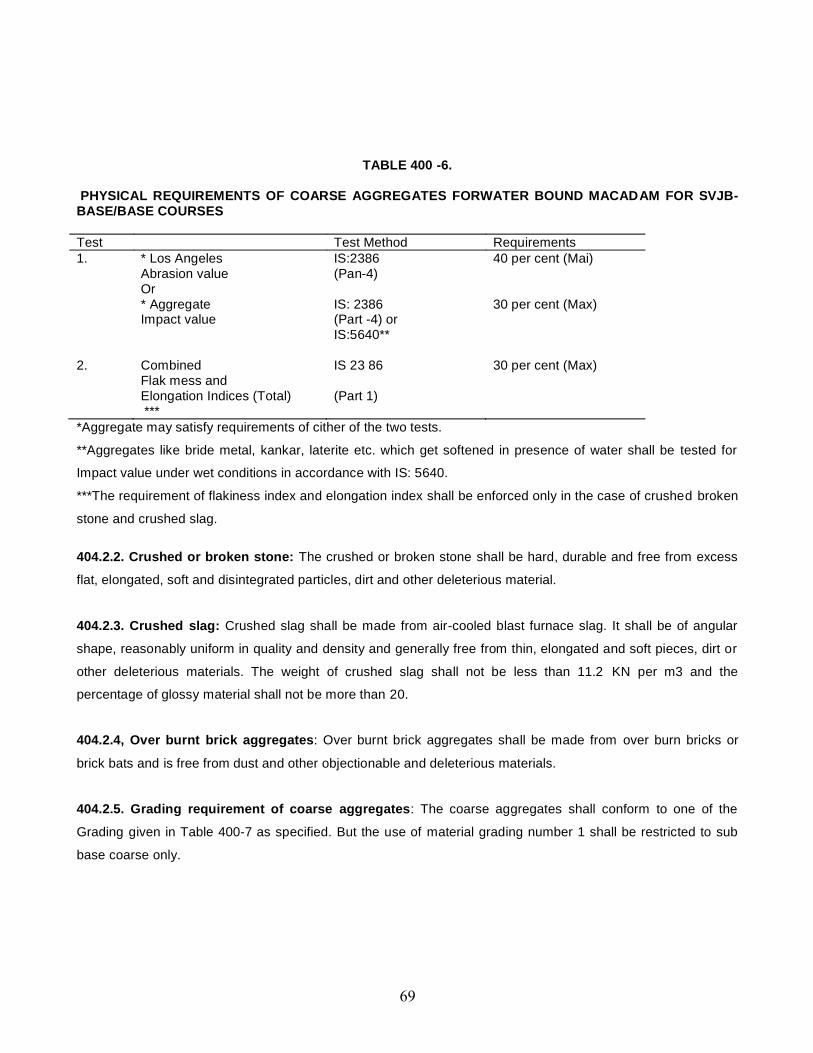
TABLE 400 -6.
PHYSICAL REQUIREMENTS OF COARSE AGGREGATES FORWATER BOUND MACADAM FOR SVJB-BASE/BASE COURSES
Test Test Method Requirements1. * Los Angeles IS:2386 40 per cent (Mai)
Abrasion value (Pan-4)Or* Aggregate IS: 2386 30 per cent (Max)Impact value (Part -4) or
IS:5640**
2. CombinedFlak mess and
IS 23 86 30 per cent (Max)
Elongation Indices (Total)***
(Part 1)
*Aggregate may satisfy requirements of cither of the two tests.
**Aggregates like bride metal, kankar, laterite etc. which get softened in presence of water shall be tested for
Impact value under wet conditions in accordance with IS: 5640.
***The requirement of flakiness index and elongation index shall be enforced only in the case of crushed broken
stone and crushed slag.
404.2.2. Crushed or broken stone: The crushed or broken stone shall be hard, durable and free from excess
flat, elongated, soft and disintegrated particles, dirt and other deleterious material.
404.2.3. Crushed slag: Crushed slag shall be made from air-cooled blast furnace slag. It shall be of angular
shape, reasonably uniform in quality and density and generally free from thin, elongated and soft pieces, dirt or
other deleterious materials. The weight of crushed slag shall not be less than 11.2 KN per m3 and the
percentage of glossy material shall not be more than 20.
404.2.4, Over burnt brick aggregates: Over burnt brick aggregates shall be made from over burn bricks or
brick bats and is free from dust and other objectionable and deleterious materials.
404.2.5. Grading requirement of coarse aggregates: The coarse aggregates shall conform to one of the
Grading given in Table 400-7 as specified. But the use of material grading number 1 shall be restricted to sub
base coarse only.
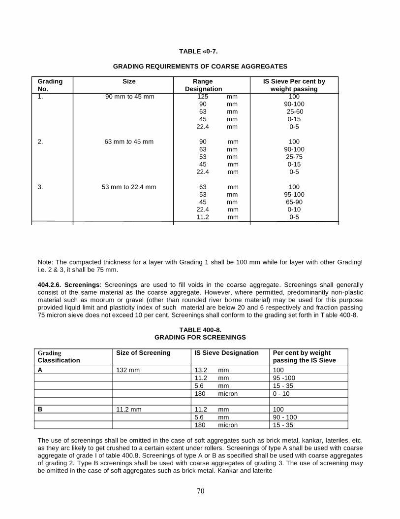
TABLE «0-7.
GRADING REQUIREMENTS OF COARSE AGGREGATES
Grading Size Range IS Sieve Per cent byNo. Designation weight passing1. 90 mm to 45 mm 125 mm 100
90 mm 90-10063 mm 25-6045 mm 0-15
22.4 mm 0-5
2. 63 mm to 45 mm 90 mm 10063 mm 90-10053 mm 25-7545 mm 0-15
22.4 mm 0-5
3. 53 mm to 22.4 mm 63 mm 10053 mm 95-10045 mm 65-90
22.4 mm 0-1011.2 mm 0-5
Note: The compacted thickness for a layer with Grading 1 shall be 100 mm while for layer with other Grading!i.e. 2 & 3, it shall be 75 mm.
404.2.6. Screenings: Screenings are used to fill voids in the coarse aggregate. Screenings shall generallyconsist of the same material as the coarse aggregate. However, where permitted, predominantly non-plasticmaterial such as moorum or gravel (other than rounded river borne material) may be used for this purposeprovided liquid limit and plasticity index of such material are below 20 and 6 respectively and fraction passing75 micron sieve does not exceed 10 per cent. Screenings shall conform to the grading set forth in T able 400-8.
TABLE 400-8.GRADING FOR SCREENINGS
Classification
Size of Screening IS Sieve Designation Per cent by weightpassing the IS Sieve
A 132 mm 13.2 mm 10011.2 mm 95 -1005.6 mm 15 - 35180 micron 0 - 10
B 11.2 mm 11.2 mm 1005.6 mm 90 - 100180 micron 15 - 35
The use of screenings shall be omitted in the case of soft aggregates such as brick metal, kankar, lateriles, etc.as they arc likely to get crushed to a certain extent under rollers. Screenings of type A shall be used with coarseaggregate of grade I of table 400.8. Screenings of type A or B as specified shall be used with coarse aggregatesof grading 2. Type B screenings shall be used with coarse aggregates of grading 3. The use of screening maybe omitted in the case of soft aggregates such as brick metal. Kankar and laterite
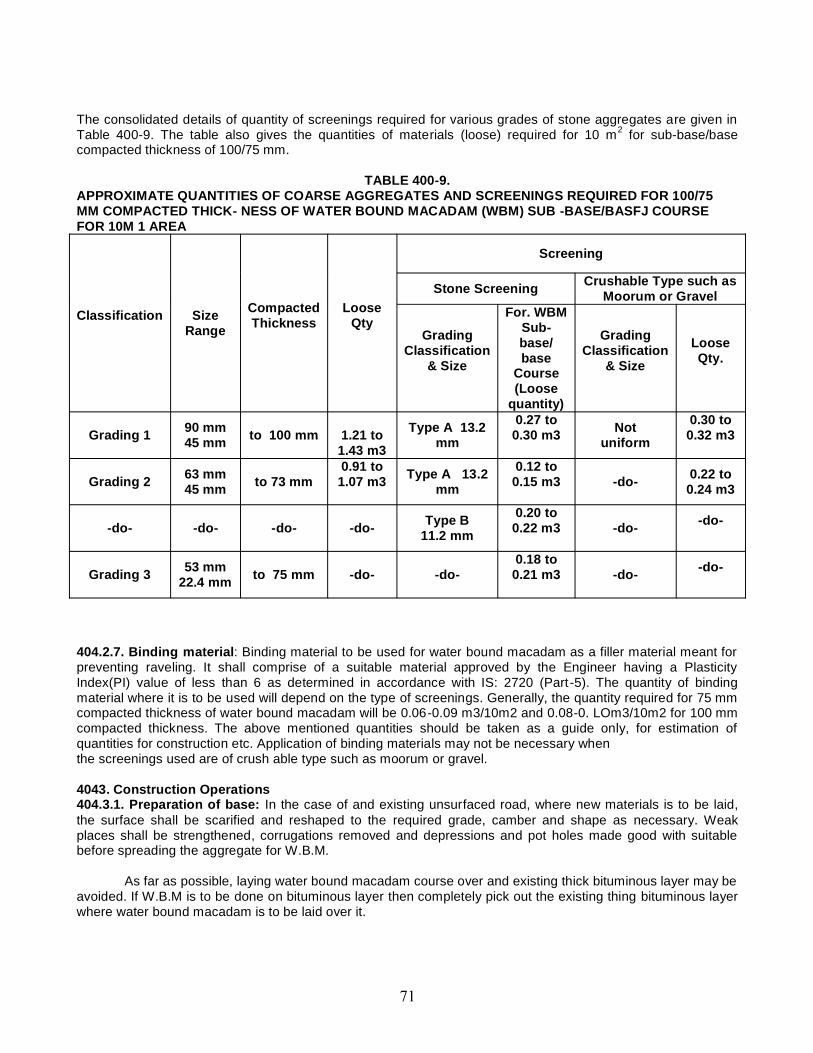
The consolidated details of quantity of screenings required for various grades of stone aggregates are given inTable 400-9. The table also gives the quantities of materials (loose) required for 10 m2 for sub-base/basecompacted thickness of 100/75 mm.
TABLE 400-9.APPROXIMATE QUANTITIES OF COARSE AGGREGATES AND SCREENINGS REQUIRED FOR 100/75MM COMPACTED THICK- NESS OF WATER BOUND MACADAM (WBM) SUB -BASE/BASFJ COURSEFOR 10M 1 AREA
Classification SizeRange
CompactedThickness
LooseQty
Screening
Stone Screening Crushable Type such asMoorum or Gravel
GradingClassification
& Size
For. WBMSub-base/base
Course(Loose
quantity)
GradingClassification
& Size
LooseQty.
Grading 1 90 mm45 mm to 100 mm 1.21 to
1.43 m3
Type A 13.2mm
0.27 to0.30 m3 Not
uniform
0.30 to0.32 m3
Grading 2 63 mm45 mm to 73 mm
0.91 to1.07 m3 Type A 13.2
mm
0.12 to0.15 m3 -do- 0.22 to
0.24 m3
-do- -do- -do- -do- Type B11.2 mm
0.20 to0.22 m3 -do- -do-
Grading 3 53 mm22.4 mm to 75 mm -do- -do-
0.18 to0.21 m3 -do- -do-
404.2.7. Binding material: Binding material to be used for water bound macadam as a filler material meant forpreventing raveling. It shall comprise of a suitable material approved by the Engineer having a PlasticityIndex(PI) value of less than 6 as determined in accordance with IS: 2720 (Part -5). The quantity of bindingmaterial where it is to be used will depend on the type of screenings. Generally, the quantity required for 75 mmcompacted thickness of water bound macadam will be 0.06-0.09 m3/10m2 and 0.08-0. LOm3/10m2 for 100 mmcompacted thickness. The above mentioned quantities should be taken as a guide only, for estimation ofquantities for construction etc. Application of binding materials may not be necessary whenthe screenings used are of crush able type such as moorum or gravel.
4043. Construction Operations404.3.1. Preparation of base: In the case of and existing unsurfaced road, where new materials is to be laid,the surface shall be scarified and reshaped to the required grade, camber and shape as necessary. Weakplaces shall be strengthened, corrugations removed and depressions and pot holes made good with suitablebefore spreading the aggregate for W.B.M.
As far as possible, laying water bound macadam course over and existing thick bituminous layer may beavoided. If W.B.M is to be done on bituminous layer then completely pick out the existing thing bituminous layerwhere water bound macadam is to be laid over it.

404.3.2. W.B.M directly over the sub grade: If water bound macadam is to be laid directly over the sub grade,
a 25 mm course of screenings (Grading B) or coarse sand shall be spread on the prepared sub grade before
application of the aggregates is taken up.
The coarse aggregate shall be spread uniformly and evenly upon the prepared base in required
quantities with a twisting motion to avoid segregation. in no case shall these be dumped in heaps directly on the
area where these are to be laid nor shall their hauling over a partly completed base be permitted. The
aggregates shall be spread uniformly to proper profile by using templates placed across the road six meters
apart. Where specified approved mechanical devices may be used to spread the aggregates uniformly. The
levels along the longitudinal direction up to which the metal shall be laid, shall be first obtained at site to the
satisfaction of engineer in charge and these shall be adhered to.
The surface of the aggregate spread shall be carefully trued up and all high or low spots remedied by
removing or adding aggregate as may be required.
The W.B.M sub base shall be normally constructed in layer of 100 mm compacted thickness for grading
I and 75 mm for grading.
404.3.3. Spreading coarse aggregates: The coarse aggregates shall be spread uniformly and evenly upon
the prepared sub grade/sub-base/ base to proper profile by using templates placed across the road about 6 m
apart, in such quantities that the thickness of each compacted layer is not more than 100 mm for Grading 1 and
75 mm for Grading 2 and 3, as specified in Clause 404.2.5. Wherever possible, approved mechanical devices
such as aggregate spreader shall be used to spread the aggregates uniformly so as to minimize the need for
manual rectification afterwards. Aggregates placed at locations which are inaccessible to the spreading
equipment, may be spread in one or more layers by any approved means so as to achieve the specified results.
The spreading shall be done from stockpiles along the side of the roadway or directly from vehicles. No
segregation of large or fine aggregates shall be allowed and the coarse aggregate as spread shall be of uniform
gradation with no pockets of fine material. The surface of the aggregates spread shall be carefully checked with
templates and all high or low spots remedied by removing or adding Aggregates as may be required. The
surface shall be checked frequently with a straight edge while spreading and rolling so as to ensure a finished
surface as per approved drawings. The coarse aggregates shall not normally be spread more than 3 days in
advance of the subsequent construction operations.
404.3.4. Rolling: (1) Immediately following the spreading of the coarse aggregate. Rolling shall be started withthree wheeled power rollers of 80 to 100 kN capacity or tandem or vibratory rollers of 80 to 100 kN static weight.The type of roller to be used shall be approved by the Engineer in charge based on trial run.
(2) Rolling shall begin from the edges gradually progressing towards the centre. Except on super elevatedportions where the rolling shall proceed from inner edge to the outer.
(3) First the edge shall be compacted with roller running forward and backward. The roller shall then moveinward parallel to the centre line of the road, in successive passes uniformly lapping preceding tracks by at leastone half widths.
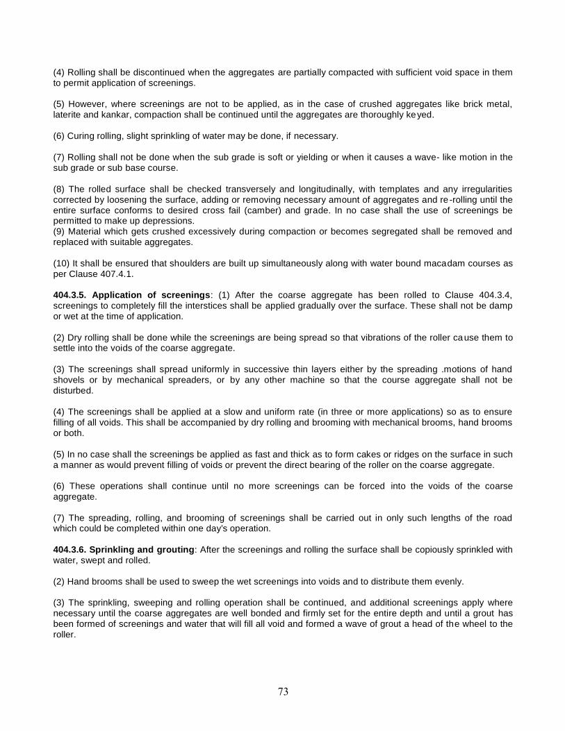
(4) Rolling shall be discontinued when the aggregates are partially compacted with sufficient void space in themto permit application of screenings.
(5) However, where screenings are not to be applied, as in the case of crushed aggregates like brick metal,laterite and kankar, compaction shall be continued until the aggregates are thoroughly keyed.
(6) Curing rolling, slight sprinkling of water may be done, if necessary.
(7) Rolling shall not be done when the sub grade is soft or yielding or when it causes a wave- like motion in thesub grade or sub base course.
(8) The rolled surface shall be checked transversely and longitudinally, with templates and any irregularitiescorrected by loosening the surface, adding or removing necessary amount of aggregates and re -rolling until theentire surface conforms to desired cross fail (camber) and grade. In no case shall the use of screenings bepermitted to make up depressions.(9) Material which gets crushed excessively during compaction or becomes segregated shall be removed andreplaced with suitable aggregates.
(10) It shall be ensured that shoulders are built up simultaneously along with water bound macadam courses asper Clause 407.4.1.
404.3.5. Application of screenings: (1) After the coarse aggregate has been rolled to Clause 404.3.4,screenings to completely fill the interstices shall be applied gradually over the surface. These shall not be dampor wet at the time of application.
(2) Dry rolling shall be done while the screenings are being spread so that vibrations of the roller cause them tosettle into the voids of the coarse aggregate.
(3) The screenings shall spread uniformly in successive thin layers either by the spreading .motions of handshovels or by mechanical spreaders, or by any other machine so that the course aggregate shall not bedisturbed.
(4) The screenings shall be applied at a slow and uniform rate (in three or more applications) so as to ensurefilling of all voids. This shall be accompanied by dry rolling and brooming with mechanical brooms, hand broomsor both.
(5) In no case shall the screenings be applied as fast and thick as to form cakes or ridges on the surface in sucha manner as would prevent filling of voids or prevent the direct bearing of the roller on the coarse aggregate.
(6) These operations shall continue until no more screenings can be forced into the voids of the coarseaggregate.
(7) The spreading, rolling, and brooming of screenings shall be carried out in only such lengths of the roadwhich could be completed within one day’s operation.
404.3.6. Sprinkling and grouting: After the screenings and rolling the surface shall be copiously sprinkled withwater, swept and rolled.
(2) Hand brooms shall be used to sweep the wet screenings into voids and to distribute them evenly.
(3) The sprinkling, sweeping and rolling operation shall be continued, and additional screenings apply wherenecessary until the coarse aggregates are well bonded and firmly set for the entire depth and until a grout hasbeen formed of screenings and water that will fill all void and formed a wave of grout a head of the wheel to theroller.
(4) Care shall be taken to see that the base or sub grade does not get damaged due to the addition of excessivequantities of water during construction.
404.3.7. Application of binding material:
(1) After the application of screenings the binding material where it is required to be used shall be appliedsuccessively in two or more thin layers at a slow and uniform rate.
(2) After each application, the surface shall be copiously sprinkled with water, the resulting slurry swept in withhand brooms, or mechanical brooms to fill the voids properly, and rolled during which water shall be applied tothe wheels of the rollers if necessary to wash down the binding material sticking to them.
(3) These operations shall continue until the resulting slurry after filling of voids, forms a wave ahead of thewheels of the moving roller.
404.3.8. Setting and drying:
(1) After the final compaction of water bound macadam course, the pavement shall be allowed to cure overnight.Next morning defective spots shall be filled with screenings or binding material as directed, lightly sprinkled withwater if necessary and rolled.
(2) No traffic shall be allowed on the road until the macadam has set.
(3) The Engineer shall have the discretion to stop hauling traffic from using the completed water boundmacadam course, if in his opinion h would cause excessive damage to the surface.
(4) The compacted water bound macadam course should be allowed to completely dry and set before the nextpavement course is laid over it.
404.4. Surface Finish and Quality Control of Work404.4.1. Same as for granular sub base 401.5.404.4.2. Same as for granular sub base. 401.5.
404.4.3. The water bound macadam work shall not be carried out when the atmospheric temperature is lessthan 0°C in the shade.
404.4.4. Reconstruction of defective macadam : where the surface irregularity of the W.B.M sub base courseexceeds the tolerance specified where the course is otherwise defective due to sub grade soil mixing with theaggregates the layer to its full thickness shall be scarified over the affected area, reshaped with added materialaforesaid manner shall not be less than 10 sqm. in no case shall depressions be filled up with screenings andbinding materials .
404.5. Same as 401.6.
404.6. Measurements for payment Water bound macadam shall be measured as finished work in position incubic meters.
404.7. RateThe Contract unit rate for water bound macadam sub-base/base course shall be payable in full for carrying outthe required operations including full compensation for all components listed below.(i) To (v) including arrangement of water used in the work as approved by the Engineer,
(i) Making arrangements for traffic except for initial treatment to verges, shoulders and construction ofdiversions;
(ii) Furnishing all materials to be incorporated in the work including all royalties, fees, rents where necessary andall leads and lifts;(iii) All labour, tools, equipment and incidentals to complete the work to the Specifications;(iv)Carrying out the work in pan widths of road where directed; and(v) Carrying out the required tests for quality control.
405. CRUSHED CEMENT CONCRETE SUB-BASE/BASE.
This work shall consist of breaking and crushing the damaged cement concrete slabs and recompactingthe same as sub-base/base course in one or more layers. Where specified, it shall also include treating thesurface of the lop layer with a penetration coat of bitumen. The work shall be performed on such widths andlengths as may be specified, in accordance with the requirements of these specifications and in conformity withthe lines, grades and cross-sections shown on the drawings or as otherwise directed by the Engineer.
406 WET MIX MACADAM SUB 4 BASE/BASES
406.1 ScopeWet mix macadam sub 4 base / bases work shall consist of laying and compacting clean, crushed, graded
aggregate and granular material, premixed with water, to a dense mass on a prepared sub-grade/sub-base/
base or existing pavement as the case may be in accordance with the requirements of these Specifications. The
material shall be laid in one or more layers as necessary to lines, grades and cross-sections shown on the
approved drawings or as directed by the Engineer-in-charge.
The thickness of a single compacted Wet Mix Macadam layer shall not be less than 75 mm and may beincreased up to 200 mm when vibrating or other approved types of compacting equipment are used, onapproval of the Engineer-in-charge.
406.2 Materials406.2.1 Aggregates406.2.1.1 Physical requirements:
(1) Coarse aggregates shall be crushed stone.
(2) If crushed gravel/shingle is used, not less than 90 per cent by weight of the gravel/shingle pieces retained on4.75 mm sieve shall have at least two fractured faces.
(3) The aggregates shall conform to the physical requirements set forth in Table 400-10 below.
Table 400-10Physical Requirements of Coarse Aggregates for Wet Mix Macadam for Sub-base/Base Courses
Test Test Method Requirements1. ^Los Angeles Abrasion value
orIS: 2386 (Part-4) 40 per cent (Max.)
^ AggregateImpact value
IS : 2386 (Part-4)or IS : 5640
30 per cent (Max.)
2. Combined Flakiness and IS : 2386 (Part-1) 30 per cent (Max.)^^
Elongation indices (Total)^ Aggregate may satisfy requirements of either of the two tests.^^ To determine this combined proportion, the flaky stone from a representative sample should first beseparated out. Flakiness index is weight of flaky stone metal divided by weight of stone sample. Only theelongated particles be separated out from the remaining (non-flaky) stone metal. Elongation index is weight ofelongated particles divided by total non-flaky particles. The value of flakiness index and elongation index sofound are added up.
If the water absorption value of the coarse aggregate is greater than 2 per cent, the soundness testshall be carried out on the material delivered to site as per IS:2386 (Part-5).
406.2.1.2 Grading requirements: The aggregates shall conform to the grading given in below.
Table 400-11Grading Requirements of Aggregates for Wet Mix Macadam
IS Sieve Designation Per cent by weight passing the IS sieve53.00 mm 10045.00 mm 95 - 10026.50 mm -22.40 mm 60 - 8011.20 mm 40 - 604.75 mm 25 - 402.36 mm 15 - 30
600.00 micron 8 - 2275.00 micron 0 - 8
Material finer than 425 micron shall have Plasticity Index (PI) not exceeding 6.The final gradation approved within these limits shall be well graded from coarse to fine and shall not
vary from the low limit on one sieve to the high limit on the adjacent sieve or vice versa.
406.3 Construction Operations406.3.1 Preparation of base: Same as for W.B.M. (Clause 404.3.1).406.3.2 Provision of lateral confinement of aggregates: While constructing wet mix macadam, arrangementshall be made for the lateral confinement of wet mix. This shall be done by laying materials in adjoiningshoulders along with that of wet mix macadam layer and following the sequence of operations described forshoulder construction (Clause 407.4.1).
406.3.3 Preparation of mix:(1) Wet Mix Macadam shall be prepared in an approved mixing plant of suitable capacity.(2) Mixing plant shall have provision for controlled addition of water and forced/ positive mixing arrangement likepug mill or pan type mixer of concrete batching plant.(3) For small quantity of wet mix work, the Engineer in charge may permit the mixing to be done in concretemixers.
(4) Optimum moisture for mixing shall be determined in accordance with IS: 2720 (Part-8) after replacing theaggregate fraction retained on 22.4 mm sieve with material of 4.75 mm to 22.4 mm size.(5) While adding water, due allowance should be made for evaporation losses.(6) However, at the time of compaction, water in the wet mix should not vary from the optimum value by morethan agreed limits.(7) The mixed material should be uniformly wet and no segregation should be permitted.
406.3.4 Spreading of mix:(1) Immediately after mixing, the aggregates shall be spread uniformly and evenly upon the prepared sub-grade/sub-base/base in required quantities.(2) It has to be check that in no case the mix be dumped in heaps.(3) The mix may be spread either by a paver finisher or motor grader.(4) For portions where mechanical means cannot be used, manual means as approved b y the Engineer incharge shall be used.(5) The surface of the aggregate shall be carefully checked with templates and all high or low spots remedied byremoving or adding aggregate as may be required. The layer may be tested by depth blocks duringconstruction. No segregation of larger and fine particles should be allowed. The aggregates as spread should beof uniform gradation with no pockets of fine materials.
406.3.5 Compaction:(1) After the mix has been laid to the required thickness, grade and cross fall/camber the same shall beuniformly compacted to the full depth with suitable roller.(2) If the thickness of single compacted layer does not exceed 100 mm, a smooth wheel roller of 80 to 100kNweight may be used.(3) For a compacted single layer up to 200 mm, the compaction shall be done with the help of vibratory roller ofminimum static weight of 80 to 100 kN equivalent capacity roller.(4) The speed of the roller shall not exceed 5 km/h.(5) In portions having unidirectional cross fall/super elevation, rolling shall commence from the lower edge andprogress gradually towards the upper edge. Thereafter, roller should progress parallel to the center line of theroad, uniformly over-lapping each preceding track by at least one third width until the entire surface has beenrolled.(6) Alternate trips of the roller shall be terminated in stops at least 1 m away from any preceding stop.(7) In camber portions, rolling should begin at the edge with the roller running forward and backward until theedges have been firmly compacted. The roller shall then progress gradually towards the center parallel to thecenter line of the road uniformly overlapping each of the preceding tracks by at least one-third width until theentire surface has been rolled.(8)Places not accessible to the roller the mixture shall be thoroughly compacted with mechanical tampers or aplate compactor. Skin patching of an area without scarifying the surface to permit proper bonding of the addedmaterial shall not be permitted.
(9) Rolling should not be done when the sub-grade is soft or yielding or when it causes a wave-like motion in thesub-base/base course or sub-grade.(10) If irregularities develop during rolling which exceed 12 mm when tested with a 3 meter straight edge, thesurface should be loosened and premixed material added or removed as required before rolling again so as toachieve a uniform surface conforming to the desired grade and cross fall.(11) In no case shall the use of unmixed material be permitted to make up the depressions.(12) Rolling shall be continued till the density achieved is at least 98 percent of the maximum dry density for thematerial as determined by the method outlined in IS: 2720 (Part-8).(13) After completion, the surface of any finished layer shall be well-closed, free from movement undercompaction equipment or any compaction planes, ridges, cracks and loose material.(14) All loose, segregated or otherwise defective areas shall be made good to the full thickness of the layer andrecomputed.
406.3.6 Setting and drying: After final compaction of wet mix macadam course, the road shall be allowed todry for 24 hours.
406.4 Opening to TrafficPreferably no vehicular traffic of any kind should be allowed on the finished wet mix macadam surface
till it has dried and the wearing course laid.
406.5 Surface Finish and Quality Control of Work406.5.1 Surface evenness: The surface finish of construction shall conform to the requirements of same asabove W.B.M.
406.5.2 Quality control: Control on the quality of materials and works shall be exercised by the Engineer incharge quality control of work will be same as W.B.M.
406.6 Rectification of Surface IrregularityWhere the surface irregularity of the wet mix macadam course exceeds the permissible tolerances or
where the course is otherwise defective due to sub-grade soil getting mixed with the aggregates, the fullthickness of the layer shall be scarified over the affected area, re-shaped with added premixed material orremoved and replaced with fresh premixed material as applicable and recomputed in accordance with Clause406.3.
The area treated with the aforesaid manner shall not be less than 5 m long and 2 m wide. In no caseshall depressions be filled up with unmixed and ungraded material or fines.
406.7 Arrangement for TrafficDuring the period of construction, arrangements for traffic shall be done as per same as for W.B.M.

406.8 Measurements for PaymentWet mix macadam shall be measured as finished work in position in cubic meters.
406.9 RateThe Contract unit rate for wet mix macadam shall be payment in full for carrying out the required operationsincluding full compensation for all components listed in Clause 401.8.
407 SHOULDERS, ISLANDS AND MEDIANS407.1 Scope
The work shall consist of constructing shoulder (hard/paved/earthen with brick or stone block edging) oneither side of the pavement, constructing median in the road dividing the carriageway into separate lanes andconstructing islands for channelising the traffic at junctions. In accordance with the requirements of theseSpecifications. And in conformity with the lines, grades and cross-sections shown on the drawings or as directedby the Engineer-in-charge.
407.2 MaterialsMaterials for Shoulder/ median/ islands may be of selected earth/granular material.
When paved shoulders are to be constructed these shall be consist of sub-base, base and surfacingcourses, as shown in the drawings and materials for the same shall conform to relevant Specifications of thecorresponding items.
407.3 Size of Shoulders/Medians/IslandsShoulder (earthen/hard/paved)/median/traffic island dimensions shall be as shown on the approved
drawings or as directed by the Engineer-in-charge.
407.4 Construction Operations407.4.1 Shoulders: The sequence of operations shall be as below.
The construction of paved shoulder is done in layers each matching the thickness of adjoiningpavement layer. Only after a layer of pavement and corresponding layers in paved and earth shoulder portionhave been laid and compacted, the construction of next layer of pavement and shoulder shall be taken up.
If the materials in adjacent layers are different, these shall be laid together and the pavement layer shallbe compacted first. The corresponding layer in paved shoulder portion shall be compacted thereafter, whichshall be followed by compaction of each shoulder layer. The adjacent layers having same material shall be laidand compacted together.

In all cases where paved shoulders have to be provided along side of existing carriageway, the existingshoulders shall be excavated in full width and to the required depth as per Clause 301.3.7. Under nocircumstances, box cutting shall be done for construction of shoulders.
Compaction requirement of earthen shoulder shall be as per Table 300-2. In the case of bituminouscourses, work on shoulder (earthen/hard/paved), shall start only after the pavement course has been laid andcompacted.
During all stages of shoulder (earthen/hard/paved) construction, the required cross fall shall bemaintained to drain off surface water.
Regardless of the method of laying, all shoulder construction material shall be placed directly on theshoulder. Any spilled material dragged on to the pavement surface shall be immediately removed, withoutdamage to the pavement, and the area so affected thoroughly cleaned.
407.4.2 Median and Islands: Median and islands shall be constructed in a manner similar to shoulder up to theroad level. Thereafter, the median and islands, if raised, shall be ra ised at least 300 mm by using kerb stones ofapproved material and dimensions and suitably finished and painted as directed by the Engineer -in-charge. Ifnot raised, the median and islands shall be differentiated from the shoulder/pavement as the case may be, asdirected by the Engineer-in-charge. The confined area of the median and islands shall be filled with local earthor granular material or any other approved material and compacted by plate compactor/power rammer. Theconfined area after filling with earth shall be turfed with grass or planted with shrubs and in case of granular fill itcan be finished with tiles/slabs as directed by the Engineer-in-charge.
407.4.3 Brick/stone block edging: The brick/stone blocks shall be laid on edge, with the length parallel to thetransverse direction of the road. They shall be laid on a bed of 25 mm sand, set carefully rolled into position by alight roller and made flush with the finished level of the pavement.
407.5 Surface Finish and Quality Control of WorksThe surface finish of construction shall be conforming to the requirements of approved drawing and as
per direction of Engineering in charge. Control on the quality of materials and works shall be exercised by theEngineer-in-charge according to the quality control of excavation/earth work/ granule fill/sub base, base/surfacing course.
407.6 Measurements for PaymentShoulder (earthen/hard/paved), island and median construction shall be measured as finished work in
position as below:i) For excavation in cu.m.ii) For earthwork/granular fill in cu.m.iii) For sub-base, base, surfacing courses in units as for respective items
iv) For kerb in running metersv) For turfing and tile/slab finish in sqm.vi) For brick/stone block edging in sqm.
407.7 RateThe Contract unit rate for shoulder (hard/paved/earthen with brick or stone block edging), island and
median construction shall be payment in full for carrying out the required operations including full compensationfor all components listed in Clause 401.8 (i) to (v) as applicable. The rate for brick/stone block edging shallinclude the cost of sand cushion.
408. CEMENT CONCRETE KERB AND KERB WITH CHANNEL408.1. GeneralKerbs and kerb with channel shall be provided in cement concrete of grade M20, in the central median and/oralong the footpath or separators as per approved drawing are as directed by the Engineering in charge. Theseshall be cast- in-situ construction with suitable kerb casting machine in all situations except at locations wherecontinues casting with equipment is not practicable. In those situations, precast concrete blocks shall be used.
408.2. Construction Operations.408.2.1. Kerbs shall be laid on firm foundation of minimum 150 mm thickness of cement concrete of M10 gradecast in situ or extended width of pavement .the foundation shall have a projection of 50 mm beyond the kerbstone. Before laying the foundation of lean concert the base shall be leveled and slightly watered to make itdamp.
408.2.2. In the median portions it the straight reaches, the kerb shall be cast in continuous lengths. In theportions where footpath is provided and/or the slope of the carriageway is towards median (as in case of superelevated portions), there shall be sufficient gap/recess left in the kerb to facilitate drainage openings.
408.2.3. After laying the kerbs and just prior to hardening of the concrete, saw-cut grooves shall be provided at10 m intervals or as specified by the Engineer in charge.
408.2.4. Kerbs on the drainage ends such as along the footpath or the median in super elevated portions shallbe cast with monolithic concrete channels as indicated in drawings. The slope of the channel towards drainagepipes shall be ensured for efficient drainage of the road surface.
408.2.5. Vertical and horizontal tolerances with respect to true line and level shall be ±6 mm.
408.3. Measurements for Payment Cement concrete kerb/kerb with channel shall be measured in linear meterfor the complete item of work. Foundation of kerb, where separately provided shall be measured in linear meterfor complete item of work.
408.4. RatesThe Contract unit rates for cement concrete kerb with channel and foundation for kerb shall be payment in fullcompensation for furnishing all materials, labour, tools, equipment for construction and other incidental costnecessary to complete the work.
409. FOOTPATHS AND SEPARATORS409.1. ScopeThe work shall consist of constructing footpaths and/or separators at locations as specified in the drawings or asdirected by the Engineer in charge. The lines, levels and dimensions shall be as per the drawings. The scope ofthe work shall include provision of all drainage arrangements as shown in the drawings or as directed.
409.2. MaterialsThe footpaths and separators shall be constructed with any of the following types:(a) Cast-in-situ cement concrete of Grade M20.(b) Precast cement concrete blocks/tiles of Grade M20. The minimum thickness of the cement concreteblock/tile shall be 25 mm and minimum size shall be 300 mm x 300 mm.(c) Natural stone slab cut and dressed from stone of good and sound quality, uniform in texture, free fromdefects and at least equal to a sample submitted by the Contractor and approved by the Engineer in charge.The minimum thickness of the natural stone slab shall be 25 mm and minimum size shall be 300 mm x 300 mm.
409.3. Construction Operations409.3.1. Drainage pipes below the footpath originating from the kerbs shall be first laid in the required slope andconnected to the drains/sumps/storm water drain/drainage chutes as per provisions of the diwings, or asspecified.
409.3.2. Portion on back side of kerbs shall be filled and compacted with granular sub-base material.
409.3.3. The base shall be prepared and finished to the required lines, levels and dimensions as indicated in thedrawings with the following ;-(3) Minimum 150 mm thick, compacted granular sub-base material.(b) Minimum 25 mm thick cement concrete of Grade M 15,Over the prepared base, precast concrete blocks/tiles/natural stone slabs and/or cast- in-situ slab shall beset/laid as described in Clauses 409.3.4 and 409.3.5 in coming clause.
409.3.4 Precast cement concrete blocks/tiles/natural stone slab : The blocks/tiles/slabs shall be set on a
layer of average 12 mm thick cement- sand mortar (1:3) laid on prepared base in such a way that there is no
rocking. The gaps between the blocks/tiles/slabs shall not be more than 12 mm and shall be filled with cement-
sand mortar (1:3).
409.3.5. Cast-in-situ cement concrete: The minimum thickness of the cement concrete shall be 25 mm and it
shall be cast on the prepared base in panels of specified size in a staggered manner. Construction joints shall
be provided.
409.4. Measurements for PaymentFootpaths and separators shall be measured in sq. meter between inside of kerbs.
409.5. RatesContract unit rates shall be inclusive of full compensation of all labour, materials, tools, equipment and
incidentals to construction of footpaths. Cost of providing pipes and arrangement for their discharge into
appropriate drainage channels shall be incidental to the construction of footpaths.
410. CRUSHER-RUN MACADAM BASE410.1. ScopeThe work of crusher-run macadam base shall consist of furnishing, placing and compacting crushed stone
aggregate sub-base and base courses constructed in accordance with the requirements set forth in this
Specification and in conformity with the lines, grades, thicknesses and cross-sections shown on the plans or as
directed by the Engineer in charge,
410.2. Construction materialsCrushed rock shall be used as a construction material. If crushed gravel/shingle is used, not less than
90 per cent by weight of the gravel/shingle pieces retained on 4.75 mm sieve shall have at least two fractured
faces. It shall be free from any organic mailer and other deleterious substances and shall be of such nature that
it can be compacted readily under watering and Stances and shall be such nature that it can be compacted
readily under watering and rolling to form a firm, stable base. The aggregate shall conform to the grading and
quality requirement shown in tables given below grading shall be approved by the Engineer in charge.
TABLE 400.12.AGGREGATE GRADING REQUIREMENTS
Sieve size Per cent passing by weight
53 mm max. size 37.5 mm max. size63 mm 100 ------45 mm 87-100 ------22.4 mm 50-85 100
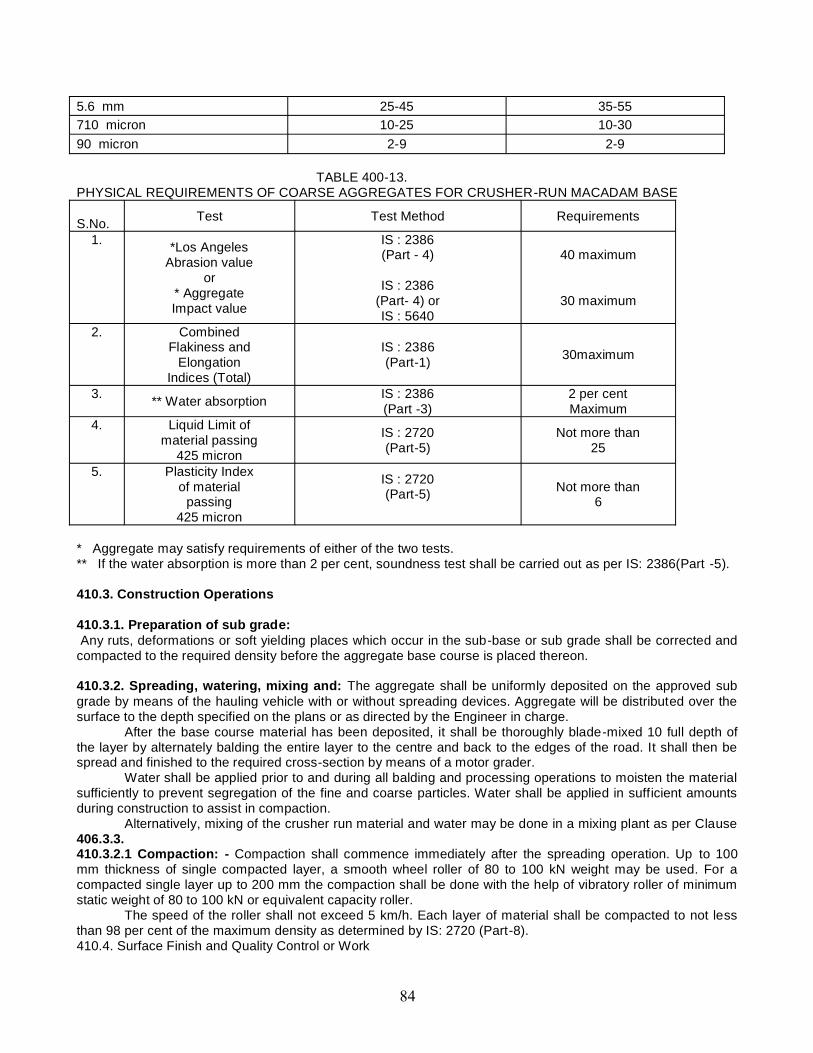
5.6 mm 25-45 35-55710 micron 10-25 10-3090 micron 2-9 2-9
TABLE 400-13.PHYSICAL REQUIREMENTS OF COARSE AGGREGATES FOR CRUSHER-RUN MACADAM BASE
S.No. Test Test Method Requirements
1. *Los AngelesAbrasion value
or* AggregateImpact value
IS : 2386(Part - 4)
IS : 2386(Part- 4) orIS : 5640
40 maximum
30 maximum
2. CombinedFlakiness and
ElongationIndices (Total)
IS : 2386(Part-1) 30maximum
3. ** Water absorption IS : 2386(Part -3)
2 per centMaximum
4. Liquid Limit ofmaterial passing
425 micron
IS : 2720(Part-5)
Not more than25
5. Plasticity Indexof material
passing425 micron
IS : 2720(Part-5) Not more than
6
* Aggregate may satisfy requirements of either of the two tests.** If the water absorption is more than 2 per cent, soundness test shall be carried out as per IS: 2386(Part -5).
410.3. Construction Operations
410.3.1. Preparation of sub grade:Any ruts, deformations or soft yielding places which occur in the sub-base or sub grade shall be corrected and
compacted to the required density before the aggregate base course is placed thereon.
410.3.2. Spreading, watering, mixing and: The aggregate shall be uniformly deposited on the approved subgrade by means of the hauling vehicle with or without spreading devices. Aggregate will be distributed over thesurface to the depth specified on the plans or as directed by the Engineer in charge.
After the base course material has been deposited, it shall be thoroughly blade-mixed 10 full depth ofthe layer by alternately balding the entire layer to the centre and back to the edges of the road. It shall then bespread and finished to the required cross-section by means of a motor grader.
Water shall be applied prior to and during all balding and processing operations to moisten the materialsufficiently to prevent segregation of the fine and coarse particles. Water shall be applied in sufficient amountsduring construction to assist in compaction.
Alternatively, mixing of the crusher run material and water may be done in a mixing plant as per Clause406.3.3.410.3.2.1 Compaction: - Compaction shall commence immediately after the spreading operation. Up to 100mm thickness of single compacted layer, a smooth wheel roller of 80 to 100 kN weight may be used. For acompacted single layer up to 200 mm the compaction shall be done with the help of vibratory roller of minimumstatic weight of 80 to 100 kN or equivalent capacity roller.
The speed of the roller shall not exceed 5 km/h. Each layer of material shall be compacted to not lessthan 98 per cent of the maximum density as determined by IS: 2720 (Part-8).410.4. Surface Finish and Quality Control or Work

The surface finish of construction shall conform to the requirements as for W.B.M.Control on the quality of materials and works shall be exercised by the Engineer in charge and shall be as perquality control of W.B.M.
410.5. Arrangements for TrafficDuring the period of construction, arrangement of traffic shall be maintained same as in the case of W.B.M.
410.6. Measurements for PaymentCrusher-run macadam base shall be measured as finished work in position in cubic meters.
410.7. RateThe Contract unit rate for crusher run macadam base shall be payment in full for carrying out the requiredoperations including full compensation for items as in Clause 401.8 (i) to (v)
500 BASE AND SURFACE COURSES (BITUMINOUS)
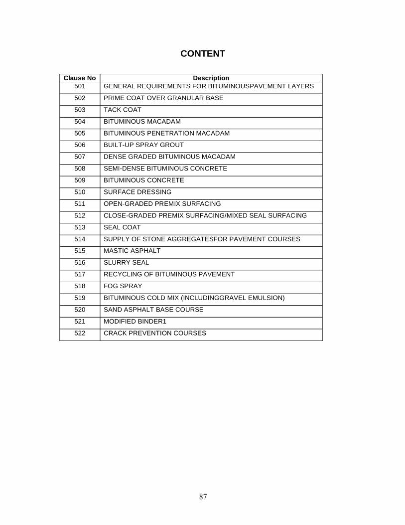
CONTENT
Clause No Description501 GENERAL REQUIREMENTS FOR BITUMINOUSPAVEMENT LAYERS
502 PRIME COAT OVER GRANULAR BASE
503 TACK COAT
504 BITUMINOUS MACADAM
505 BITUMINOUS PENETRATION MACADAM
506 BUILT-UP SPRAY GROUT
507 DENSE GRADED BITUMINOUS MACADAM
508 SEMI-DENSE BITUMINOUS CONCRETE
509 BITUMINOUS CONCRETE
510 SURFACE DRESSING
511 OPEN-GRADED PREMIX SURFACING
512 CLOSE-GRADED PREMIX SURFACING/MIXED SEAL SURFACING
513 SEAL COAT
514 SUPPLY OF STONE AGGREGATESFOR PAVEMENT COURSES
515 MASTIC ASPHALT
516 SLURRY SEAL
517 RECYCLING OF BITUMINOUS PAVEMENT
518 FOG SPRAY
519 BITUMINOUS COLD MIX (INCLUDINGGRAVEL EMULSION)
520 SAND ASPHALT BASE COURSE
521 MODIFIED BINDER1
522 CRACK PREVENTION COURSES
501. GENERAL REQUIREMENTS FOR BITUMINOUSPAVEMENT LAYERS501.1. GeneralBituminous pavement courses shall be made using the materials described in the followingparagraph. For work of bituminous pavement layers the manual for construction and supervisionof bituminous work shall also be applicable.
501.1.1 Use of bituminous work’s:-(a) Use of prime coat:-(i) To plug the capillary voids.(ii) To coat and bond loose materials on the surface.(iii) To harden or toughen the surface.(iv) To promote adhesion between the layer being primed and superimposed bituminous layer.
(b) Use of Tack coat: - It is used to ensure a bond between the new construction and the oldsurface.
(c) Use of Bituminous penetration macadam: - The penetration macadam specification was invogue as a base material for pavement construction may decades ago. It is not advocated for usein heavily trafficked situations, for which the more efficient coated macadam is preferred. In India,it is still used remote areas where it is difficults to transport mixing and laying equipment. It can beused as a temporary emergency material to repair a pavement damaged by rains and floods.
(d) Use of Built up spray grout:- It is used only for emergency repair work and other temporaryconstruction.
(e) Use of Surface dressing:- Surface dressing is use in a variety of situation to perform variousfunctions these are:-(i) As a surfacing in its own right, in the case of relatively lightly trafficked roads, over gravel orother untreated road bases, often to prevent gravel loss, and particularly to reduce dust nuisance.(ii) To protect freshly laid water bound macadam or similar unbound base from the action ofpneumatic tyred vehicles which, unless prevented from doing so, tend to draw out much of thefines from the macadam and thus deprive it of stability.(iii) To act as a water proof seal and prevent the entry of water into the lower layers of a roadpavement. For longer term maintenance of roads. It is then known also as a seal coat.(iv) To arrest the deterioration of an existing bituminous surface which is showing sings ofdistress, as part of periodic maintenance of roads, it is then known also as a seal coat.(v) To increase the skid resistance of smooth surface.(vi) To act as a temporary bituminous surfacing on newly constructed roads so as to allow forsettlements due to traffic before costlier bituminous layers are provided.
(f) Use of Bituminous macadam:- A layer of bituminous macadam serves as a base/s bindercourse, laid immediately after mixing on a previously prepared base.
(g) Use of Dense graded bituminous material: Dense bituminous:- Dense bituminousmacadam is used as a base/binder course for pavements subjected to heavy traffic.
(h) Use of Dense graded bituminous material: Semi Dense Bituminous Concrete: It is usedas a binder/wearing course on roads carrying relatively lower traffic in terms of equivalentstandard axle loads(esa), generally less than 10 msa.
(i)Use of Dense graded bituminous material: Bituminous concrete:- A bituminous concretelayer serves as a wearing course for heavily trafficked highways.
(j) Use of open grade premix surfacing:- It serves as a wearing course on lightly traffickedroads or for temporary improvement and maintenance.
(k) Use of Premix seal coat:- It is intended for sealing the voids in the bituminous surface overwhich it is laid and is needed only for those surface, which are textured eg: an open gradedpremix carpet.
(l) Use of Slurry seal: - Slurry seals can be used for both preventive and corrective maintenanceof aged bituminous surfaces and surface with fine cracks. They seal surface cracks, fill voids andminor depressions, and provide a more even riding surface or base for further treatment. Theymay also be used on top of single coat surface dressing.
(m)Use of bituminous cold mix (including gravel emulsion): designed cold mix:- Bituminouscold mixes are used in situation where hot-mix plants are not readily available including forworking in remote areas and maintenance operations.
(n) Use of Bituminous cold mix (including gravel emulsion): recipe cold mix: - Thesemixtures are considered suitable for use only for emergency and minor repair work and temporaryroad surface improvement.
(o) Use of Modified binder: emerging materials:- The use of these material is expected toresult in an extended service life of bituminous pavement subjected to heavy traffic and inextreme climate conditions, thus justifying the extra cost of adding modifier/fibers. otheradvantages includes: lower temperature susceptibility, higher resistance to ageing, higher fatiguelife, higher resistance to cracking and better adhesion between aggregates and binder.
501.2. Materials501.2.1. Binder:-(a) Bitumen: - Bitumen is a petroleum product. The colour of bitumen is dark brown to black.(b) Choice of binder: - Binders are manufacture in many different grades of consistency fromvery fluid that pour at atmospheric temperature to hard material. The road engineer is presentedwith a somewhat bewildering number of alternatives. The choice of a particular type or surfacingmaterial is determined by economic as well by technical consideration. There are alwaysmovement in the road surface due to exposed to weather or for other reasons it become brittle atlow temperature high stresses are developed when movements occur and the bond betweenadjacent stones can then be easily destroyed. To reduce the effect of hardening as soft a gradeof bitumen as practicable should be used without danger of the surface "pushing" or" waving".
Road surfacing vary widely in their texture in the more open textured type the bitumenacts as an adhesive between stone and road or between stone and stone, and in the dense closetextured type the bitumen act in combination with the fine aggregate as a plastic mortar. Thesebinder are required to remain in a plastic condition so that the surfacing can accommodate itselfwithout cracking to small movements induce in the road by temperature variations, moisturechanges and traffic. Binder must also be sufficiently viscous and resilient possessing shockabsorbing qualities to resist the forces of the traffic (impact). Adhesion and viscosity are thus theimportant physical properties of bitumen.
Bitumen is not suited to damp or water logged areas as regards road construction work.The higher the viscosity the greater is the strength of the surfacing up to a limit when
viscosity reaches some high values it imparts brittleness to the material. The viscosity of thebinder should be selected according to the intensity of the traffic on the road and also thetemperature in which work is to be carried out. Low viscosity binder can be laid cold and highviscosity binder has to be laid hot and is used in warmer weather. A more viscous binder isspecified for the more heavily trafficked roads to resist distortion under the intense traffic andshould be laid warm or hot within a few hours of manufactures. Where binders of relatively lowviscosity are used the resulting surfacing is initially soft and may be deformed if it receives trafficimmediately after being laid.
Adhesion: - The construction or maintenance of road/is primarily a problem of adhesion. Bitumenadheres well to all stones normally used as road aggregates provided they are dry and not undulydusty. Moisture is the chief cause of stripping and swelling. Some stones have greater surface
affinity for water than for bitumen, and when a coated stone comes into contact with water thereis tendency for the binder to be displaced from the surface of the stone. In a road mixturecontaining fines susceptible to expansions when wet stripping is accompanied by swelling of theroad mass.
The adhesion of both bitumen is weakened by the presence of water and there is atendency for the binder to be displaced or stripper from the stone. The higher the viscosity to thebinder the grater the resistance to this effect.
The binder in a freshly laid surface dressing or surfacing is particularly sensitive to thedisplacing action of water if prolonged rain falls before the binder has reached a sufficiently highviscosity the adhesive joint may be broken and disintegration set in . Although failures of this typeare not frequent but when they do occur there is no remedial measure a new surfacing has to belaid.
The properties of the aggregate, especially its surface texture, have an important bearingon adhesion. Smooth a glassy surface and both fine textured and coarsely crystalline, generallygive poor adhesion. The rough textured stones generally give the best adhesion. There is anindication that low silica content rocks have better resistance to stripping than high silica contentrocks of similar texture. Limestones have good adhesive properties except when crystalline.
Properties of hot application bitumen’s30/40 Medium hard grade. Standard grade for grouting in uniform size aggregate work pre
mixing surface painting where a heavy application is considered necessary.60/70 Sometime used in lieu of 80/100 penetration. in very hot localities where a slightly harder
grade is required.80/100 Standard grade for surface painting per mixing grouting in graded aggregate dense
surface and seal coats.180/20 Very soft grade for light surface dressing or in very cold climates pre mixed carpets.
(c) Penetration: - is a measure of hardness or consistency and therefore of primary importanceas an indication of suitability for any particular construction or condition. This test is probably themost important of all tests on bitumen .penetration is measured by a standard penetrometer.Penetration is the distance measured in unit of 1/10 mm that a standard blunt point needle willpenetration a sample at 25 degree centigrade. When the needle is loaded with 100 grams appliedfor 5 seconds.
The higher the penetration numbers the softer the bitumen. The lower the penetration thehigher will be the melting point and lower the ductility in other word, the harder the bitumen thehigher will be the melting point but the ductility will be less for the bitumen becomes more brittlethe harder it is. The harder the bitumen the quicker it sets soft bitumen takes comparatively alonger time to set.
Normally bitumen with greater penetration is used for surface painting and semi groutingwork and bitumen with lesser penetration are used for full grouting work.
Bitumen cut back Bitumen:-Cutback are softened bitumen (solid thinned with a volatile distillate such as petrol, kerosene,diesel oil or tar oil), which can be used without heating or require only l ight heating. Bitumencutbacks are classified into three types:Rapid curing (RC) - Light type for use as primer.Medium curing (MC)- heavy type for surface dressing.Slow curing (SC) - heavy type for pre mixingEach these three types of cutback are produced in six grades, numbered from 0 to 5 (designatedas R-0, RC-3, MC-3, or SC-5, etc.) according to their viscosities or fluidity the percentage ofbitumen increasing as the number rise. For example SC-0 contains about 40 percent bitumenwhilst CS-5 contains about 80 percent bitumen. (RC-1, MC-, SC-1 are all of the same viscosity).
Number 0 and 1 are of very low consistency and are fluid at ordinary temperatures and flow likeoil. Number 2 and 3 are thicker and flow slowly at ordinary room temperatures. Number 4 and 5are thick and sticky almost semi solid and poured with difficulty until heated.
Cutback bitumen is used for cold mix specifications as it will coat cold chippings in drummixers, unlike a straight run bitumen a cutback does not harden too rapidly on contact with coldaggregate.
Bitumen Emulsions: - bitumen emulsified in water is called bitumen emulsion. Bitumen blendedwith petroleum distillate is known as cutback bitumen.
Bitumen emulsions are chocolate brown colour. If mixed with petrol, kerosene, or diesel oil,globules of water will appear. Emulsions have the advantage that they can be applied cold andcan be used on damp surface and wet aggregate although they are not always successful if laidin wet weather. Cutback can be used when the road surface and also the aggregate are dry.)Emulsions are not as competent, especially under heavy traffic as hot bitumen, and should beused with discretion. They are not also cheap in real cost as about half the volume is water.(Emulsion contain water cutbacks contain solvent.)
There are three grades of emulsions - (i) Quick breaking or rapid setting (RS), (ii) Mediumbreaking or medium setting (MS) and (iii) Slow braking or Slow setting (SS). (The terms curing orcutting are also used instead of setting and breaking). The time taken for breaking of an emulsionis the measure of its grade and the type of work which to be used.
In order to decide whether the sample is suitable for surface dressing or grouting for coatedmacadam or for soil stabilization it is necessary to know whether it is breaking or slow breaking.The breaking rate can be assessed as follows:
Put some clean gravel or crushed stone into a pan and try to mix the emulsion with itusing a metal spoon. a fast breaking emulsion cannot be mixed in this way as it breaks gummingup the spoon with bitumen. While a slow breaking emulsion will mix perfectly coating the spoonthe pan and aggregate,
Normally two types of bitumen emulsions are used for road work in INDIA -(i) quickbraking and (ii) slow breaking quick breaking emulsions are used for surface painting tack, coats,seals coats, and grouting. The emulsions for such works should have minimum 50% of bitumencontent slow breaking emulsion are used for pre mixing and patch repairs during wet weather.This emulsion should have min: 60 per cent of bitumen content.
Bitumen emulsion is applied at atmospheric temperature but no work should be carriedout in frosty weather as emulsion is liable to be adversely affected by frost. Not work should beundertaken when it is actually raining.
501.2.2. Coarse Aggregates: The coarse aggregates shall consist of crushed rock, crushedgravel or other hard material retained on the 2.36 mm sieve. They shall be clean, hard, anddurable, of cubical shape, free from dust, organic or other deleterious matter. Where theContractor’s selected source of aggregates have poor affinity for bitumen, as a condition for theapproval of that source, the bitumen shall be treated with approved anti -stripping agents, as perthe manufacturer’s recommendations, without additional payment. Before approval of the sourcethe aggregates shall be tested for stripping. The aggregates shall satisfy the physicalrequirements set forth in the individual relevant clause for the material in question. Wherecrushed gravel is proposed for use as aggregate, not less than 90% by weight of the crushedmaterial retained on the 4.75 mm sieve shall have at least two fractured faces.
501.2.3. Fine Aggregates: Fine aggregates shall consist of crushed or naturally occurringmaterial, or a combination of the two, passing 2.36mm sieve and retained on the 75 micron sieve.They shall be clean, hard, durable, dry and free from dust, organic or other deleterious matter.
501.2.4. Source of material: The source of all materials to be used on the project must be testedto the satisfaction of and be expressly approved by the Engineer in charge The Engineer incharge may from time to time withdraw approval of a specific source, or attach conditions to theexisting approval. Any change in aggregate source for bituminous mixes, will require a new mixdesign, and laying trials, where the mix is based on a job mix design. Stockpiled from differentsources, approved or otherwise, shall be kept separate, such that there is no contaminationbetween one material and another. Each source submitted for approval shall contain sufficientmaterial for at least 5 days work.
501.3. MixingPre-mixed bituminous materials, including bituminous macadam, dense bituminous macadam,semi-dense bituminous concrete and bituminous concrete, shall be prepared in a hot mix plant ofadequate capacity and capable of yielding a mix of proper and uniform quality with thoroughlycoated aggregates. Appropriate mixing temperatures can be given in Table 500-5 of theseSpecifications; the difference in temperature between the aggregate and binder should at no timeexceed 14°C. In order to ensure uniform quality of the mix and better coating of aggregates, thehot mix plant shall be calibrated from time to time are as directed by the Engineer in charge.
If a continuous mixing-plant is to be used for mixing the bituminous bound macadam; theContractor must demonstrate by laboratory analysis that the cold feed combined grading is withinthe grading limits specified for that bituminous bound material. In the case of a designed job mix,the bitumen and filler content shall be derived using this combined grading.
501.4 TransportingBituminous materials shall be transported in clean insulated vehicles, and unless otherwiseagreed by the Engineer in charge shall be covered while in transit or waiting tipping. Subject tothe approval of the Engineer in charge thin coating of diesel or lubricating oil may be applied tothe interior of the vehicle to prevent sticking and to facilitate discharge of the material.
501.5. Laying501.5.1. Weather and seasonal limitations: Laying shall not be done during rain, fog and duststorms and while free standing water is present on the surface to be covered. After rain, thebituminous surface, prime or tack coat shall be blown off with a high pressure air jet to removeexcess moisture, Laying of bituminous mixtures shall not be carried out when the air temperatureat the surface on which it is to be laid is below 10°C or when the wind speed at any temperatureexceeds 40 km/h at 2m height unless specifically approved by the Engineer in charge.
501.5.2. Cleaning of surface for bituminous work: The surface shall be cleaned of all looseand extraneous matter by means of a mechanical broom or any other approved equipment /method as specified in the contract. The use of a high pressure air jet from a compressor toremove dust or loose matter shall be available full time on the site, unless otherwise specified inthe Contract.
501.5.3. Spreading: Except in areas where a mechanical paver cannot access, bituminousmaterials shall be spread, leveled and tamped by an approved self-propelled paving machine. Assoon as possible after arrival at site, the materials shall be supplied continuously to the paver andlaid without delay. In areas with restricted space where a mechanical pave r cannot be used, thematerial shall be spread, raked and leveled with suitable hand tools by experienced staff, andcompacted to the satisfaction of the Engineer in charge.
The rate of delivery of material to the paver shall be regulated to enable the paver tooperate continuously. The travel rate of the paver, and its method of operations, shall be adjustedto ensure an even and uniform flow of bituminous material across the screed, free from dragging,tearing and segregation of the material.
The minimum thickness of material laid in each paver pass shall be in accordance withthe minimum values given in the relevant parts of these Specifications. When laying bindercourse or wearing course approaching an expansion joint of a structure, machine laying shall stop300mm short of the joint. The remainder of the pavement up to the joint, and the corresponding
area beyond it, shall be laid by hand, and the joint or joint cavity shall be kept clear of surfacingmaterial.
Bituminous material, with a temperature greater than 145°C, shall p not be laid or,deposited on bridge deck waterproofing systems, unless precautions against heat damage havebeen approved by the Engineer in charge.
Hand placing of pre -mixed bituminous materials shall only be permitted in the followingcircumstances:(a) For laying regulating courses of irregular shape and varying thickness.(b) In confined spaces where it is impracticable for a paver to operate.(c) For footways.(d) At the approaches to expansion joints at bridges, viaducts or other structures.(e) For laying mastic asphalt in accordance with Clause 515.(f) For filling of potholes.(g) Where directed by the Engineer in charge.
Manual spreading of pre -mixed wearing course material or the addition of such material by hand-spreading to the paved area, for adjustment of level, shall only be permitted in the followingcircumstances:(a) At the edges of the layers of material and at gullies and manholes.(b) At the approaches to expansion joints at bridges, viaducts or other structures.(c) As directed by the Engineer in charge.
501.5.4. Cleanliness and overlaying: Bituminous material shall be kept clean anduncontaminated. The only traffic permitted to run on bituminous material to be overlaid shall bethat engaged in laying and compacting the next course or, where a binder course is to be sealedor surface dressed, that engaged on such surface treatment. Should any bituminous material.Become contaminated the Contractor shall make it good to the satisfaction of the Engineer incharge, in compliance with Clause 501.8. Binder course material shall not remain uncovered byeither the wearing course or surface treatment, whichever is specified in the Contract, for morethan three consecutive days after being laid. The Engineer in charge may extend this period, bythe minimum amount of time necessary, because of weather conditions or for any other reason. Ifthe surface of the base course is subjected to traffic, or not covered within three days, a tack coatshall be applied, as directed by the Engineer in charge.
501.6. Compaction(i) Compaction of bituminous materials shall commence as soon as possible after laying.
(ii)Compaction shall be substantially completed before the temperature falls below the minimumrolling temperatures.
(iii)Rolling of the longitudinal joints shall be done immediately behind the paving operation. Afterthis, rolling shall commence at the edges and progress towards the centre longitudinally exceptthat on super elevated and unidirectional cambered portions.
(iv)Compaction shall progress from the lower to the upper edge parallel to the centre line of thepavement. Rolling shall continue until all roller marks have been removed from the surface.
(v)All deficiencies in the surface after laying shall be made good by the attendants behind thepaver, before initial rolling is commenced.
(vi)The initial or breakdown rolling shall be done with 8-10 tonnes dead weight smooth-wheeledrollers.
(vii)The intermediate rolling shall be done with 8-10 tonnes dead weight or vibratory roller or witha pneumatic tyred roller of 12 to 15 tonnes weight having nine wheels, with a tyre pressure of atleast 5.6 kg/sqcm.
(viii)The finish rolling shall be done with 6 to 8 tonnes smooth wheeled tandem rollers.
(ix) Bituminous materials shall be rolled in a longitudinal direction, with the driven rolls nearest thepaver.
(x)The roller shall first compact material adjacent to joints and then work from the lower to theupper side of the layer, overlapping on successive passes by at least one-third of the width of therear roll or, in the case of a pneumatic -tyred roller, at least the nominal width of 300mm.
(xi)Where compaction is to be determined by density of cores the requirements to prove theperformance of rollers shall apply in order to demonstrate that the specified density can beachieved. In such cases the Contractor shall nominate the plant, and the method by which heintends to achieve the specified level of compaction and finish at temperatures above theminimum specified rolling temperature. Laying trials shall then demonstrate the acceptability ofthe plant and method used.
(xii)In portions with super-elevated and uni-directional camber, after the edge has been rolled, theroller shall progress from the lower to the upper edge.
(xiii)Rollers should move at a speed of not more than 5 km per hour.
(xiv)The roller shall not be permitted to stand on pavement which has not been fully compacted.
(xv)Necessary precautions shall be taken to prevent dropping of oil, grease, petrol or otherforeign matter on the pavement either when the rollers are operating or standing.
(xvi)The wheels of rollers shall be kept moist with water, and the spray system provided with themachine shall be in good working order, to prevent the mixture from adhering to the wheels. Onlysufficient moisture to prevent adhesion between the wheels of rollers and the mixture should beused. Surplus water shall not be allowed to stand on the partially compacted pavement.
501.7. JointsWhere longitudinal joints are made in pre-mixed bituminous materials, the materials shall be fullycompacted and the joint made flush in one of the following ways; only method iii shall be used fortransverse joints:(i) By heating the joints with an approved joint beater when the adjacent width is being laid, butwithout cutting back or coating with binder. The heater shall raise the temperature of the full depthof material, to within the specified range of minimum rolling temperature and maximumtemperature at any stage for the material, for a width not less, Am 75 mm, The Contractor shallhave equipment available, for use in the event of a beater breakdown, to form joints by method.(ii) By using two or more pavers operating in echelon, where this is practicable, and in sufficientproximity for adjacent widths to be fully compacted by continuous rolling;(iii) By cutting back the exposed joint, for a distance equal to the specified layer thickness, to avertical face, discarding all loosened material and coating the vertical face completely, with80/100 penetration grade hot bitumen, or cold-applied bitumen, or polymer modified adhesivebitumen tape with a minimum thickness of 2 mm, before the adjacent width is laid. All joints shallbe offset at least 300 mm from parallel joints in the layer beneath or as directed, and in a layoutapproved by the Engineer in charge. Joints in the wearing course shall coincide with either thelane edge or the lane marking, which ever is appropriate. Longitudinal joints shall not be situatedin wheel track zones.
501.8. Preparation of Surface501.8.1. General: This work shall consist of preparing an existing granular or black-toppedsurface bituminous course. The work shall be performed on such widths and lengths as shown onthe approved drawings or as instructed by the Engineer in charge. The existing surface shall befirm and clean, and treated with Prime or Tack coat as shown on the drawings as otherwisestated in the Contract.
501.8.2. Materials501.8.2.1. Scarifying the existing granular base course and re-laying the granular surface:The material used shall be coarse aggregate saved from the scarification of the existing granularbase course supplemented by fresh coarse aggregate and screenings so that aggregates andscreenings thus supplemented correspond to Clause 404: Water Bound Macadam or Clause 406:Wet Mix Macadam of the Ministry’s Specification for Road and Bridge Works (third revision) 1995.
501.8.2.2. For patching potholes sealing cracks: Where the existing surface to be overlaid isbituminous, any existing potholes and cracks shall be repaired and sealed as stated below.(1)The existing bituminous surface should be inspected and all potholes and patch areas madefree o any loose, defective material. The edges of all potholes shall be cut/trimmed with handtools vertically to form rectangular shape and shall be thoroughly cleaned with wire brush,compressed air or other approved means, all dust and loose materials should be removed fromsite. Layers below the level of bituminous construction should be replaced using material ofequivalent specification to the original construction and degree of compaction. The area ofbituminous construction should be primed and / or tacked with an emulsion (meeting requirementof IS: 8887) depending on whether the lower area is granular or bituminous in nature. The sidesof the excavated position should be painted with tack coat material using a hand brush/sprayer.
(2)The bituminous patching material should be either a hot mix or a cold mix, adopting thereactive specification. The bituminous mixture, prepared in a plant of suitable capacity should beplaced in layers of not more than 100 mm (loose) and compacted in layers with roller/platecompactor/ hand roller/ rammer to the desired compaction standard.
(3) In the final layer the mix should be spread slightly proud of the surface so that after rolling, thesurface shall be flush with the adjointing surface.
(4) Where required, a seal coat should be applied as per the specified procedure. the surfacelevels should be checked using a 3m straight edge.
Crack sealing:-(1) The fine cracks (less than 3 mm in width) should be sealed by for spray, which is a very lightapplication of low viscosity slow setting emulsion. Prior to this treatment it is important that thesurface is thoroughly cleaned, preferably with compressed air. The fog spray should be applied ata rate of 0.5-1.0 liter/m2 of the specified emulsion. Using 0.5 -1.0 liter /m2 of the specifiedemulsion, using an approved hand held sprayer.
(2)The wide cracks (more than 3 mm in width) should be filled with crusher dust or otherapproved fine material passing 4.75 mm sieve to a level about 5 mm below the road surfacelevel. After sweeping the surface clear of dust slow setting emulsion should be poured in thecracks, minimizing any spillage. If spillage does occur, crusher dust should be applied to bolt upthe spillage. Isolated areas, with wide cracks, shall be cut and patched.
501.8.2.3. For profile corrective course: A profile corrective course for correcting the existingpavement profile shall be laid to varying thickness as shown on the approved drawings. Theprofile corrective course shall be laid to tolerances and densities as specified for wearing course ifa single layer, or base course, if it is to be covered with a wearing course layer.
501.8.2.4. Profile corrective course and its application: The type of material for use as profilecorrective course shall be as shown on the approved drawings or as directed by the Engineer incharge. Where it is to be laid as part of the overlay/strengthening course, the profile correctivecourse material shall be of the same specification as that of the overlay/ strengthening course.However, if provided as a separate layer, it shall be of the specification and details given in theapproved drawings.
(i)Any high spots in the existing surface shall be removed by a milling machine or other approvedmethod, and all loose material shall be removed to the satisfaction of theEngineer
(ii)Where the maximum thickness of profile corrective course will be not more than 40 mm, theprofile corrective course shall be constructed as an integral part of the overlay course. In othercases, the profile corrective course shall be constructed as a separate layer, adopting suchconstruction procedures and using such equipment as approved by the Engineer in charge, to laythe specified type of material, to thickness and tolerance as specified, for the course, to beprovided.
501.8.3. Construction Operations501.8.3.1. Preparing existing granular surface:(i) All loose materials shall be removed from existing granular surface.(ii)The existing granular surface shall be lightly watered where the profile corrective course to beprovided as a separate layer is also granular.(iii)Where the profile corrective course of bituminous material is to be laid over the existinggranular surface, the existing granular surface shall be primed, after removal of all loose material.(iv)The surface finish of all granular layers on which bituminous works are to be placed, shall befree form dust. All such layers must be capable of being swept, after the removal of any non -integral loose material, by means of a mechanical broom, without shedding significant quantitiesof material and dust removed by air jet, washing, or other means approved by the Engineer incharge. After cleaning the surface shall be correct to line and level, within the tolerances specifiedfor base course.
501.8.3.2. Scarifying existing bituminous surface: Where required, the existing bituminouslayer in the specified width shall be removed with care and without causing undue disturbance tothe underlying layer, by a suitable method approved by the Engineer in charge. After removal, allloose and disintegrated material, the underlying layers which might have been disturbed shouldbe suitably reworked and compacted to line and level. After supplementing the base material asnecessary with suitable fresh stone, the compacted finished surface shall be primed inaccordance with Clause 502. Reusable materials shall be stacked as directed by the Engineer incharge within one kilometer of their origin.
501.8.3.3. Patching of potholes and sealing of cracks: shall be done as per clause 501.8.2.2.
501.8.3.4. Laying the profile corrective course501.8.3.4.1. Laying on granular base: After preparing the granular surface in accordance withClauses 501.8.3.1 and 501.8.3.2, the profile corrective course shall be laid using material asdescribed in Clauses 501.8.2.3 and 501.8.2.4, or as otherwise described in the Contract, andcompacted to the requirements of the particular Specification.
501.8.3.4.2. Laying on existing bituminous surface: The existing bituminous surface shall beprepared in accordance with Clause 501.8.3.3, and after applying a tack coat conforming toClause 503, the bituminous profile corrective course shall be laid and compacted to therequirements of the particular Specification.
501.8.3.4.3. Correction of local depressions: Where local sags or depressions occur in theexisting pavement, a specific filling operation shall be instructed by the Engineer in charge.
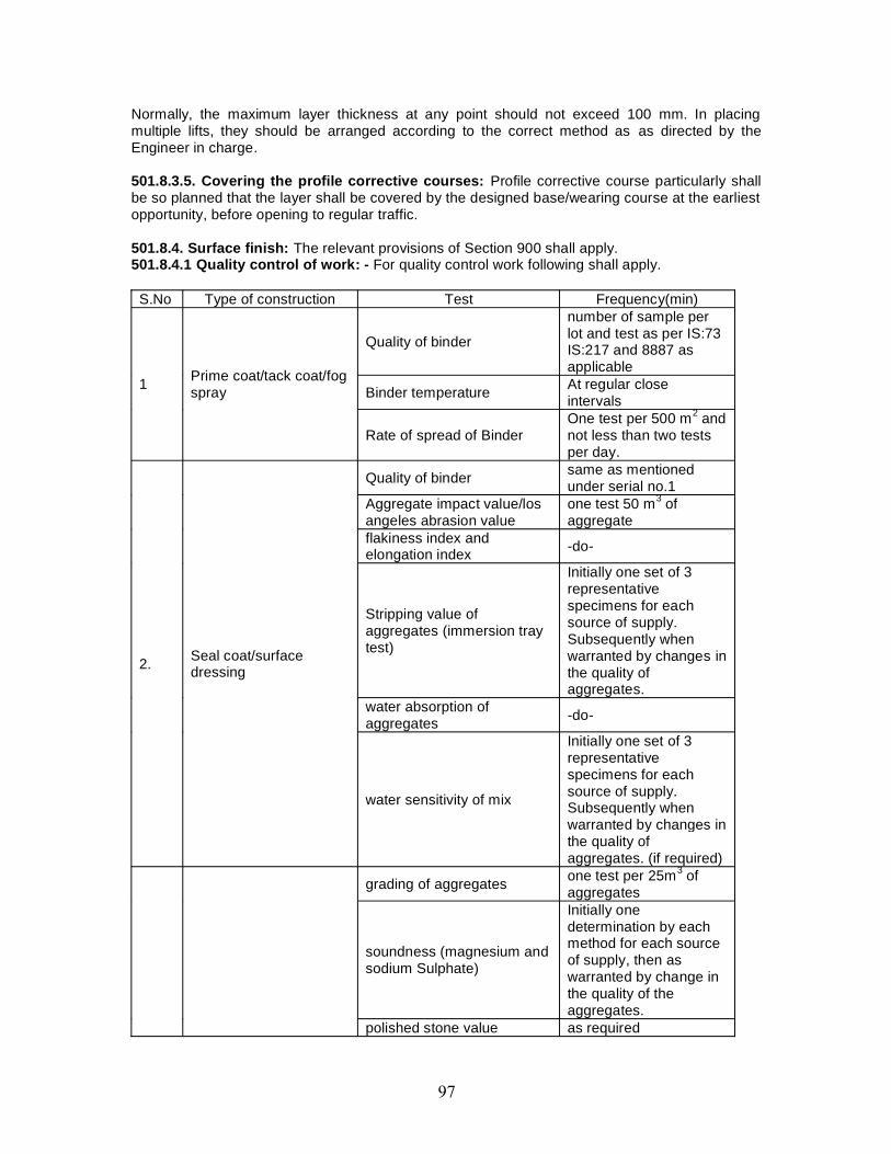
Normally, the maximum layer thickness at any point should not exceed 100 mm. In placingmultiple lifts, they should be arranged according to the correct method as as directed by theEngineer in charge.
501.8.3.5. Covering the profile corrective courses: Profile corrective course particularly shallbe so planned that the layer shall be covered by the designed base/wearing course at the earliestopportunity, before opening to regular traffic.
501.8.4. Surface finish: The relevant provisions of Section 900 shall apply.501.8.4.1 Quality control of work: - For quality control work following shall apply.
S.No Type of construction Test Frequency(min)
1 Prime coat/tack coat/fogspray
Quality of binder
number of sample perlot and test as per IS:73IS:217 and 8887 asapplicable
Binder temperature At regular closeintervals
Rate of spread of BinderOne test per 500 m2 andnot less than two testsper day.
2. Seal coat/surfacedressing
Quality of binder same as mentionedunder serial no.1
Aggregate impact value/losangeles abrasion value
one test 50 m3 ofaggregate
flakiness index andelongation index -do-
Stripping value ofaggregates (immersion traytest)
Initially one set of 3representativespecimens for eachsource of supply.Subsequently whenwarranted by changes inthe quality ofaggregates.
water absorption ofaggregates -do-
water sensitivity of mix
Initially one set of 3representativespecimens for eachsource of supply.Subsequently whenwarranted by changes inthe quality ofaggregates. (if required)
grading of aggregates one test per 25m3 ofaggregates
soundness (magnesium andsodium Sulphate)
Initially onedetermination by eachmethod for each sourceof supply, then aswarranted by change inthe quality of theaggregates.
polished stone value as required
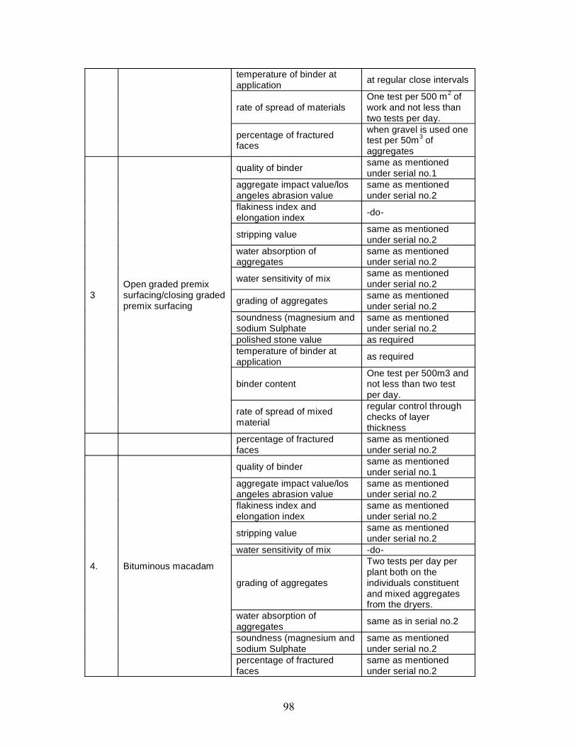
temperature of binder atapplication at regular close intervals
rate of spread of materialsOne test per 500 m2 ofwork and not less thantwo tests per day.
percentage of fracturedfaces
when gravel is used onetest per 50m3 ofaggregates
3Open graded premixsurfacing/closing gradedpremix surfacing
quality of binder same as mentionedunder serial no.1
aggregate impact value/losangeles abrasion value
same as mentionedunder serial no.2
flakiness index andelongation index -do-
stripping value same as mentionedunder serial no.2
water absorption ofaggregates
same as mentionedunder serial no.2
water sensitivity of mix same as mentionedunder serial no.2
grading of aggregates same as mentionedunder serial no.2
soundness (magnesium andsodium Sulphate
same as mentionedunder serial no.2
polished stone value as requiredtemperature of binder atapplication as required
binder contentOne test per 500m3 andnot less than two testper day.
rate of spread of mixedmaterial
regular control throughchecks of layerthickness
percentage of fracturedfaces
same as mentionedunder serial no.2
4. Bituminous macadam
quality of binder same as mentionedunder serial no.1
aggregate impact value/losangeles abrasion value
same as mentionedunder serial no.2
flakiness index andelongation index
same as mentionedunder serial no.2
stripping value same as mentionedunder serial no.2
water sensitivity of mix -do-
grading of aggregates
Two tests per day perplant both on theindividuals constituentand mixed aggregatesfrom the dryers.
water absorption ofaggregates same as in serial no.2
soundness (magnesium andsodium Sulphate
same as mentionedunder serial no.2
percentage of fracturedfaces
same as mentionedunder serial no.2
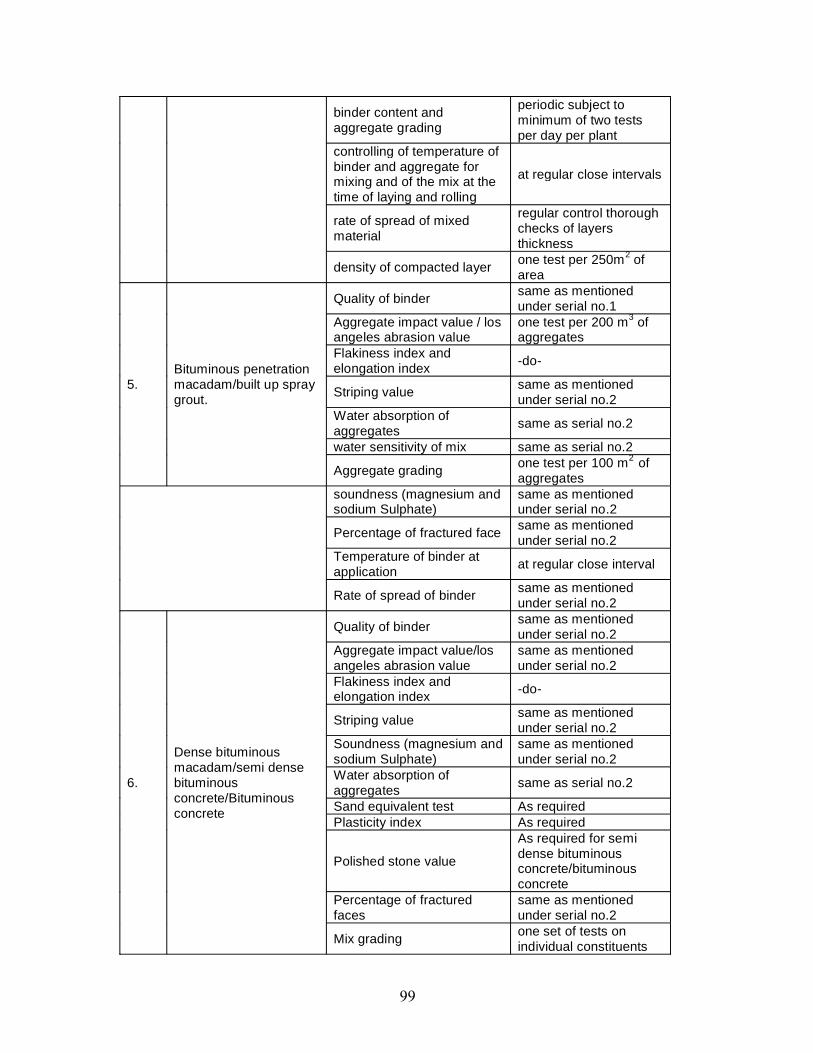
binder content andaggregate grading
periodic subject tominimum of two testsper day per plant
controlling of temperature ofbinder and aggregate formixing and of the mix at thetime of laying and rolling
at regular close intervals
rate of spread of mixedmaterial
regular control thoroughchecks of layersthickness
density of compacted layer one test per 250m2 ofarea
5.Bituminous penetrationmacadam/built up spraygrout.
Quality of binder same as mentionedunder serial no.1
Aggregate impact value / losangeles abrasion value
one test per 200 m3 ofaggregates
Flakiness index andelongation index -do-
Striping value same as mentionedunder serial no.2
Water absorption ofaggregates same as serial no.2
water sensitivity of mix same as serial no.2
Aggregate grading one test per 100 m2 ofaggregates
soundness (magnesium andsodium Sulphate)
same as mentionedunder serial no.2
Percentage of fractured face same as mentionedunder serial no.2
Temperature of binder atapplication at regular close interval
Rate of spread of binder same as mentionedunder serial no.2
6.
Dense bituminousmacadam/semi densebituminousconcrete/Bituminousconcrete
Quality of binder same as mentionedunder serial no.2
Aggregate impact value/losangeles abrasion value
same as mentionedunder serial no.2
Flakiness index andelongation index -do-
Striping value same as mentionedunder serial no.2
Soundness (magnesium andsodium Sulphate)
same as mentionedunder serial no.2
Water absorption ofaggregates same as serial no.2
Sand equivalent test As requiredPlasticity index As required
Polished stone value
As required for semidense bituminousconcrete/bituminousconcrete
Percentage of fracturedfaces
same as mentionedunder serial no.2
Mix grading one set of tests onindividual constituents
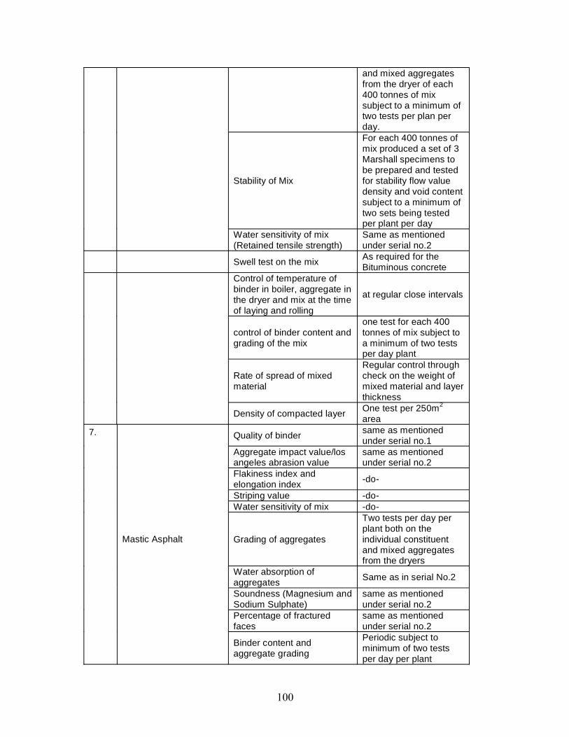
and mixed aggregatesfrom the dryer of each400 tonnes of mixsubject to a minimum oftwo tests per plan perday.
Stability of Mix
For each 400 tonnes ofmix produced a set of 3Marshall specimens tobe prepared and testedfor stability flow valuedensity and void contentsubject to a minimum oftwo sets being testedper plant per day
Water sensitivity of mix(Retained tensile strength)
Same as mentionedunder serial no.2
Swell test on the mix As required for theBituminous concrete
Control of temperature ofbinder in boiler, aggregate inthe dryer and mix at the timeof laying and rolling
at regular close intervals
control of binder content andgrading of the mix
one test for each 400tonnes of mix subject toa minimum of two testsper day plant
Rate of spread of mixedmaterial
Regular control throughcheck on the weight ofmixed material and layerthickness
Density of compacted layer One test per 250m2
area7.
Mastic Asphalt
Quality of binder same as mentionedunder serial no.1
Aggregate impact value/losangeles abrasion value
same as mentionedunder serial no.2
Flakiness index andelongation index -do-
Striping value -do-Water sensitivity of mix -do-
Grading of aggregates
Two tests per day perplant both on theindividual constituentand mixed aggregatesfrom the dryers
Water absorption ofaggregates Same as in serial No.2
Soundness (Magnesium andSodium Sulphate)
same as mentionedunder serial no.2
Percentage of fracturedfaces
same as mentionedunder serial no.2
Binder content andaggregate grading
Periodic subject tominimum of two testsper day per plant
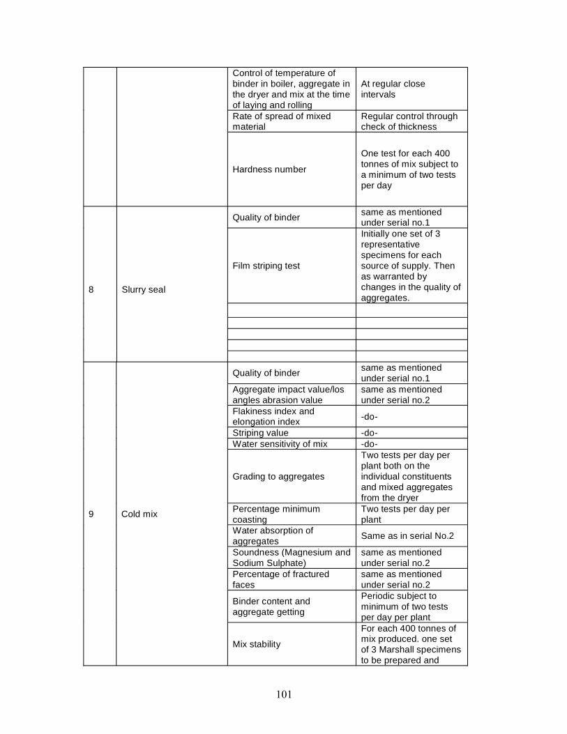
Control of temperature ofbinder in boiler, aggregate inthe dryer and mix at the timeof laying and rolling
At regular closeintervals
Rate of spread of mixedmaterial
Regular control throughcheck of thickness
Hardness number
One test for each 400tonnes of mix subject toa minimum of two testsper day
8 Slurry seal
Quality of binder same as mentionedunder serial no.1
Film striping test
Initially one set of 3representativespecimens for eachsource of supply. Thenas warranted bychanges in the quality ofaggregates.
9 Cold mix
Quality of binder same as mentionedunder serial no.1
Aggregate impact value/losangles abrasion value
same as mentionedunder serial no.2
Flakiness index andelongation index -do-
Striping value -do-Water sensitivity of mix -do-
Grading to aggregates
Two tests per day perplant both on theindividual constituentsand mixed aggregatesfrom the dryer
Percentage minimumcoasting
Two tests per day perplant
Water absorption ofaggregates Same as in serial No.2
Soundness (Magnesium andSodium Sulphate)
same as mentionedunder serial no.2
Percentage of fracturedfaces
same as mentionedunder serial no.2
Binder content andaggregate getting
Periodic subject tominimum of two testsper day per plant
Mix stability
For each 400 tonnes ofmix produced. one setof 3 Marshall specimensto be prepared and
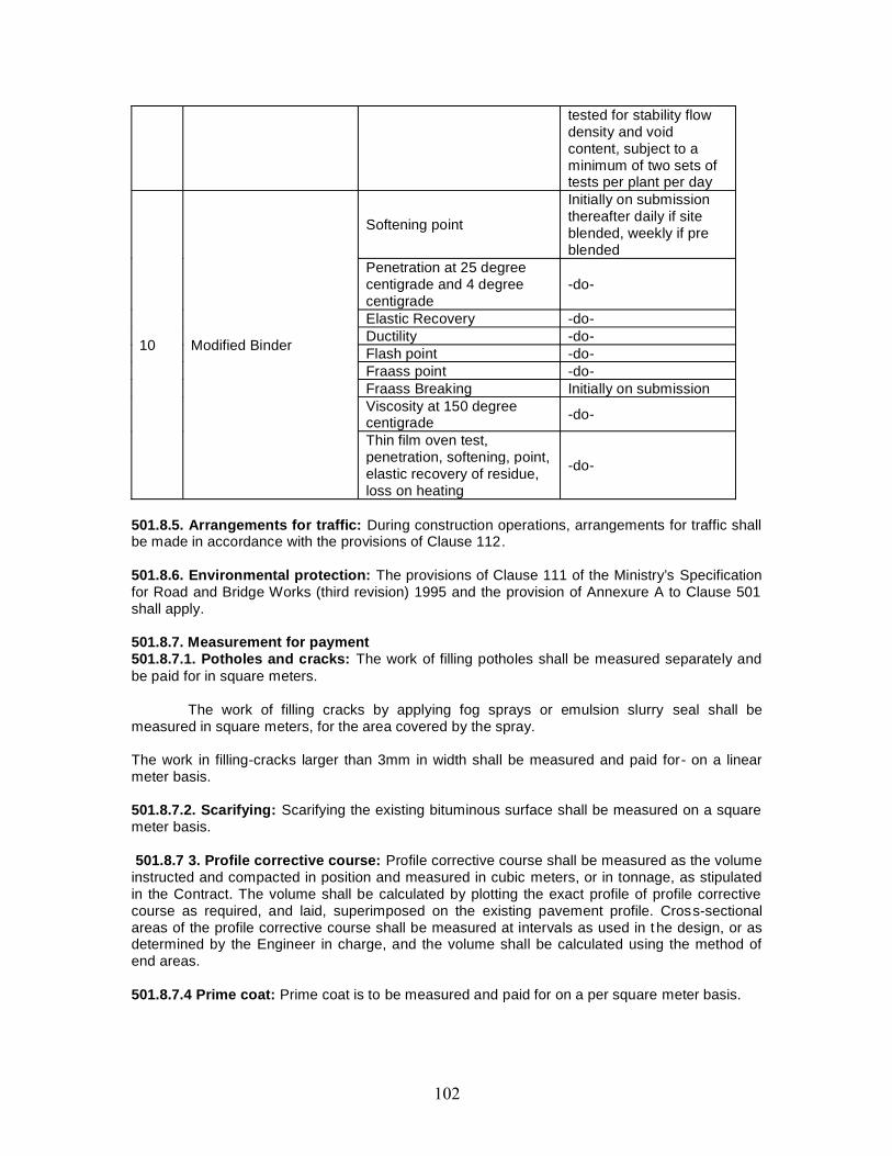
tested for stability flowdensity and voidcontent, subject to aminimum of two sets oftests per plant per day
10 Modified Binder
Softening point
Initially on submissionthereafter daily if siteblended, weekly if preblended
Penetration at 25 degreecentigrade and 4 degreecentigrade
-do-
Elastic Recovery -do-Ductility -do-Flash point -do-Fraass point -do-Fraass Breaking Initially on submissionViscosity at 150 degreecentigrade -do-
Thin film oven test,penetration, softening, point,elastic recovery of residue,loss on heating
-do-
501.8.5. Arrangements for traffic: During construction operations, arrangements for traffic shallbe made in accordance with the provisions of Clause 112.
501.8.6. Environmental protection: The provisions of Clause 111 of the Ministry’s Specificationfor Road and Bridge Works (third revision) 1995 and the provision of Annexure A to Clause 501shall apply.
501.8.7. Measurement for payment501.8.7.1. Potholes and cracks: The work of filling potholes shall be measured separately andbe paid for in square meters.
The work of filling cracks by applying fog sprays or emulsion slurry seal shall bemeasured in square meters, for the area covered by the spray.
The work in filling-cracks larger than 3mm in width shall be measured and paid for- on a linearmeter basis.
501.8.7.2. Scarifying: Scarifying the existing bituminous surface shall be measured on a squaremeter basis.
501.8.7 3. Profile corrective course: Profile corrective course shall be measured as the volumeinstructed and compacted in position and measured in cubic meters, or in tonnage, as stipulatedin the Contract. The volume shall be calculated by plotting the exact profile of profile correctivecourse as required, and laid, superimposed on the existing pavement profile. Cross-sectionalareas of the profile corrective course shall be measured at intervals as used in the design, or asdetermined by the Engineer in charge, and the volume shall be calculated using the method ofend areas.
501.8.7.4 Prime coat: Prime coat is to be measured and paid for on a per square meter basis.
501.8.7.5 Tack coat: This is to be a PROVISIONAL item, which may be used in-part or not at all,at the Engineer in charges direction, and is to be measured and paid if used, on a square meterbasis.
501.8.8. Rates501.8.8.1. Rate for scarifying: The contract unit rate for scarifying existing bituminous surfaces,including repairing / reworking disturbed underlying layers and removing and stacking reusable /unusable materials, shall include for but not necessarily be limited to, the cost of all labour, supplyof materials needed for repair /reworking, hire charges of tools and plant, and transportation ofscarified materials within 1000 m of their origin.
501.8.8.2. Rate for premixed bituminous material: The contract unit rate for premixedbituminous material shall be payment in full for carrying out the required operations including fullcompensation for, but not necessarily limited to:(i) Making arrangements for traffic to Clause 112 except for initial treatment to verge, shouldersand construction of diversions;(ii) Preparation of the surface to receive the material.(iii) Providing all materials to be incorporated in the work including arrangement for stock yards,all royalties, fees rents where necessary and all leads and lifts;(iv) Mixing, transporting, laying and compacting the mix, as specified.(v) All labour, tools, equipment, plant including installation of hot mix plant, power supply its andall machinery, incidental to complete the work to these Specifications;(vi) Carrying out the work in part widths of the road where directed;(vii) Carrying out all tests for control of quality; and(viii) The rate shall cover the provision of bitumen at the rate specified in the contract, with theprovision that the variation i n actual percentage of bitumen used will be assessed and thepayment adjusted accordingly.(ix) The rates for premixed material are to include for all wastage in cutting of joints etc.(x) The rates are to include for all necessary testing, mix design, transporting and testing ofsamples, and cores. If there is not a project specific laboratory, the Contractor must arrange tocarry out all necessary testing at an outside Laboratory, approved by the Engineer in charge, andall costs incurred are deemed to be included in the rate quoted forthe material.(xi) The cost of all plant and laying trials as specified to prove the mixing and laying methods isdeemed to be included in the Contractor’s rates for the material.
501.8.8.3. Rate for potholes: The rate shall include for breaking out, trimming edges, cleaningout, painting edges and bottom with bitumen, and filling and compacting the excavation with thespecified material. The rate should be inclusive of all plant, tools, labour and materials, transport,and disposal of surplus material, the contract unit rate for sealing cracks by applying fog sprayshall be inclusive of providing all materials, tools, labour and plant and carrying out the work.
Rate for sealing cracks:-The contract unit rate for sealing cracks by providing emulsion slurryseal shall be as set forth in Clause 516.9. The contract unit rate for crack sealing 3mm to 6mmcracks with straight run or other specified bitumen shall be based on either a square meter basis,or linear meter of cracks as measured, as stipulated by the Contract. The contract unit rate forcracks between 6mm and 15mm is to be measured on a linear meter basis, and the rate is toinclude for all materials, tools, plant, labour, and transport.
PROTECTION OF THE ENVIRONMENT1. General1.1. This section of the Specification sets out limitations on the Contractor’s activities specificallyintended to protect the environment.1.2. The Contractor shall take all necessary measures and precautions and otherwise ensurethat the execution of the works and all associated operations on site or off -site are carried out in
conformity with statutory and regulatory environmental requirements including those prescribedelsewhere in this document.1.3. The Contractor shall take all measures and precautions to avoid any nuisance ordisturbance arising from the execution of the Works. This shall wherever possible be achieved bysuppression of the nuisance at source rather than abatement of the nuisance once generated.1.4. In the event of any spoil, debris, waste or any deleterious substance from the Site beingdeposited on any adjacent land, the Contractor shall immediately remove all such material andrestore the affected area to its original state to the satisfaction of the Engineer in charge.
2. Water Quality2.1. The Contractor shall prevent any interference with the supply to or abstraction from, andprevent any pollution of, water resources (including underground percolating water) as a result ofthe execution of the Works.2.2. All water and other liquid waste products arising on the Site shall be collected and disposedof at a location on or off the Site and in a manner that shall not cause either nuisance o r pollution.2.3. The Contractor shall not discharge or deposit any matter arising from the execution of theWorks into any waters except with the permission of the Engineer in charge and the regulatoryauthorities concerned.2.4. The Contractor shall at all times ensure that all existing stream courses and drains within,and adjacent to, the Site are kept safe and free from any debris and any materials arising fromthe Works.
3. Air Quality3.1. The Contractor shall devise and arrange methods of working to minimize dust, gaseous orother air-borne emissions and carry out the Works in such a manner as to minimize adverseimpacts on air quality.3.2. The Contractor shall utilize effective water sprays during delivery manufacture, processingand handling of materials when dust is likely to be created, and to dampen stored materialsduring dry and windy weather. Stockpiles of friable materials shall be covered with cleantarpaulins, with application of sprayed water during dry and windy weather. Stockpiles of materialor debris shall be dampened prior to their movement, except where this is contrary to theSpecification.3.3. Any vehicle with an open load-carrying area used for transporting potentially dust producingmaterial shall have properly fitting side and tail boards. Materials having the potential to producedust shall not be loaded to a level higher than the side and tail boards, and shall be covered witha clean tarpaulin in good condition. The tarpaulin shall be properly secured and extend at least300 mm over the edges of the side and tail boards.3.4. In the event that the Contractor is permitted to use gravel or earth roads for haulage, heshall provide suitable measures for dust palliation, if these are, in the opinion of the Engineer incharge, necessary. Such measures may include spraying the road surface with water at regularintervals.
4. Noise:4.1. The Contractor shall: consider noise as an environmental constraint in his planning andexecution of the Works.4.2. The Contractor shall take all necessary measures for controlling unnecessary are excessivenoise due to machine. The Contractor shall use all necessary measures and shall maintain allplant and silencing equipment in good condition so as to minimize the noise emission duringconstruction works.
5. Control of Wastes5.1. The Contractor shall control the disposal of all forms of waste like, all forms of fuel andengine oils, all types of bitumen, cement, surplus aggregates, gravels, bituminous mixtures etc.The Contractor shall make specific provision for the proper disposal of these and any other wasteproducts, conforming to local regulations and acceptable to the Engineer in charge.
6. Emergency Response6.1. The Contractor shall plan and provide for remedial measures to be implemented in theevent of occurrence of emergencies such as spillages of oil or bitumen or chemicals.
7. Measurement7.1. No separate measurement shall be made in respect of compliance by the Contractor withthe provisions of this Section of the Specification. The Contractor shall be deemed to have madeallowance for such compliance with these provisions in the preparation of his prices for items ofwork included in the Bills of Quantities and full compensation for such compliance will be deemedto be covered by them.
502. PRIME COAT OVER GRANULAR BASE502.1. GeneralThis work shall consist of the application of a single coat of low viscosity liquid bituminousmaterial to a porous granular surface preparatory to the superimposition of bituminous treatmentor mix.
Prime coat is an initial application of a binder to an absorbent road surface.A coat of low viscosity binder is applied as a primer over an existing road surface (generally awater bound macadam) if it is dust, porous and absorptive, to develop a bond between theexisting road and the surface. Road built with laterite, kankar, brick metal, moorum, etc. , (waterbound macadam) are absorptive. The function of the primer is to penetrate the existing surface,fill the pores, bond together any loose material, and in general, produce a firm impervious layer toserve as a foundation for the material to be superimposed.
Priming coast are not given on cement concrete or dense bituminous surface, but a trackcost is applied instead, a coat of primer is not usually required where surfacing is to be done withbar.
502.2. Materials502.2.1. Primer: The choice of a bituminous primer shall depend upon the porositycharacteristics of the surface to be primed as classified in IRC: 16. These are:(i) Surfaces of low porosity; such as wet mix macadam and water bound macadam,(ii) Surfaces of medium porosity; such as cement stabilized soil base,(iii) Surfaces of high porosity; such as a gravel base.
502.2.2. Primer viscosity: The type and viscosity of the primer shall comply with therequirements of IS 8887, as sampled and tested for bituminous primer in accordance with thesestandards. Guidance on viscosity and rate of spray is given in Table 500-1.
TABLE 500-1.VISCOSITY REQUIREMENT AND QUANTITY OF LIQUID BITUMINOUS PRIMERType of surface Kinematics
Viscosity of Primer at 60°C(Centistokes) (kg)
Quantity Of LiquidBituminous MaterialPer 10 Sq. m.
Low porosity 30 – 60 6 to 9Medium porosity 70 -140 9 to 12High porosity 250-500 12 to 15
502.2.3. Choice of primer: The primer shall be bitumen emulsion, complying with IS 8887 of atype and grade as specified in the Contract or as directed by the Engineer in charge.
The choice of a bituminous prime, as to its viscosity and quantity, depend upon theporosity characteristics of the surface to be primed. The more porous the surface and cooler theweather, the lower should be the viscosity. Conversely if too much material is being absorbed, amore viscous grade should be used. A more viscous primer should be used on open texturedroads and a thin primer on close textured roads. The amount applied should ordinarily beabsorbed in 24 hour. The primer should be applied uniformly by means of a sprayer.
502.3. Weather and Seasonal Limitations
Bituminous primer shall not be applied to a wet surface during a dust storm or when the weatheris foggy, rainy or windy or when the temperature in the shade is less than 10°C. Surfaces whichare to receive emulsion primer should be damp, but no free or standing water shall be present.
502.4. Construction502.4.1. Equipment: The primer distributor shall be a self-propelled or towed bitumen pressuresprayer equipped for spraying the material uniformly at specified rates and temperatures. Handspraying of small & areas, inaccessible to the distributor, or in narrow strips shall be sprayed witha pressure hand sprayer, or as directed by the Engineer in charge.
502.4.2. Preparation of road surface: The surface to be primed should be swept clean free fromdust, and for best result, be dry. Care shall be taken not to disturb the interlocked aggregated.Large irregularities, pot holes, depression, etc., should be repaired prior to priming.
In the case of very dry and dusty surface it is often sound practice to moisten the roadslightly before application of the primer.
502.4.3. Application of bituminous primer: The viscosity and rate of application of the primershall be as specified in the Contract, or as determined by site trials carried out as directed by theEngineer in charge. The method for application of the primer will depend on the type ofequipment to be used, size of nozzles, pressure at the spray bar and speed of forwardmovement. The Contractor shall demonstrate at a spraying trial, that the equipment and methodto be used is capable of producing a uniform spray, within the tolerances specified.
502.4.4. Curing of primer and opening to traffic:(i)A primed surface shall be allowed to cure for at least 24 hours or such other period as is foundto be necessary to allow all the volatiles to evaporate before any subsequent surface treatment ormix is laid.(ii)Any unabsorbed primer shall first be blotted with an application of sand, using the minimumquantity possible.(iii)A primed surface shall not be opened to traffic other than that necessary to lay the nextcourse.(iv)A very thin layer of clean sand may be applied to the surface of the primer, to prevent theprimer picking up under the wheels of the paver and the trucks delivering bituminous material tothe paver.
502.5 Quality control of work: - It shall be as per clause 501.8.4.1.
502.6. Arrangements for TrafficDuring construction operations, arrangements for traffic shall be made as per direction of theEngineer in charge.
502.7. Measurement for PaymentPrime coat shall be measured in terms of surface area of application in square meters.
502.8. RateThe contract unit rate for prime coat with adjustments as described in Clause 502.7 shall bepayment in full for carrying out the required operations including full compensation for allcomponents listed in Clause 401.8 (i) to (v) of the Ministry’s Specification for Road and BridgeWorks (third revision) 1995, and as applicable to the work specified in these Specifications.Payment shall be made on the basis of the provision of prime coat at an application rate of 0.6 kgper square meter, with adjustment, plus or minus, for the variation between this amount and theactual amount approved by the Engineer in charge after the preliminary trials.
503. TACK COAT503.1. GeneralA track coat is given over the old road surface if it is smooth or of cement concert, and onbituminous base courses if the surface is dry, hungry and dusty before laying a thin premixed
carpet to ensure a proper bond between the base and the superimposed mat or carpet whichmust be made to adhere to the old road surface. Work of tack coat shall consist of the applicationof a single coat of low viscosity liquid bituminous material to an existing bituminous road surfacepreparatory to the superimposition of a bituminous mix, when specified in the Contract orinstructed by the Engineer in charge.
503.2. Materials503.2.1. Binder: The binder used for tack coat shall be bitumen emulsion complying with IS 8887of a type and grade as specified in the Contract or as directed by the Engineer in charge.
503.3. Weather and Seasonal Limitations(i)Bituminous material shall not be applied to a wet surface or during a dust storm or when theweather is foggy, rainy or windy or when the temperature in the shade is less than 10°C.(ii)Where the tack coat consists of emulsion, (he surface shall be slightly damp, but not wet.
503.4. Construction503.4.1. .Equipment: The tack coat distributor shall be as per clause 502.4.1.
503.4.2. Preparation of base:(i)The surface on which the tack coat is to be applied shall be clean and free from dust, dirt, andany extraneous material.(ii)Immediately before the application of the tack coat, the surface shall be swept clean with amechanical broom, and high pressure air jet, or by other means as directed by the Engineer incharge.
503.4.3. Application of tack coat:(i)The application of tack coat shall be at the rate specified in the Contract, and shall be applieduniformly.(ii)If rate of application of Tack Coat is not specified in the contract then it shall be at the ratespecified in Table given below
TABLE 500-2Rate of Application of Tack Coat
S.No. Type of Surface Quantity of liquid bituminousmaterial in Kg per sq.m. area
(i) Normal bituminous surfaces 0.20 to 0.25(ii) Dry and hungry bituminous surface 0.25 to 0.30(iii) Granular surfaces treated with primer 0.25 to 0.30(iv) Non bituminous surfaces
(a) Granular base (not primed) 0.35 to 0.40(b) Cement concrete pavement 0.30 to 0.35
(iii)The normal range of spraying Temperature for a bituminous emulsion shall be 20°C to 70°CThe method of application of the tack coat will depend on the type of equipment to be used, sizeof nozzles, pressure at the spray bar, and speed of forward movement. The Contractor shalldemonstrate at a spraying trial, that the equipment and method to be used is capable ofproducing a uniform spray, within the tolerances specified.(iv)Where the material to receive an overlay is a freshly laid bituminous layer that has not beensubjected to traffic or contaminated by dust, a tack coat is not mandatory where the overlay iscompleted within two days.

503.4.4. Curing of tack coat:(i)The tack coat shall be left to cure until all the volatiles have evaporated before any subsequentconstruction is started.(ii)No plant or vehicles shall be allowed on the tack coat other than those essential for theconstruction.
503.5. Quality Control of WorkFor control of the quality of materials supplied and the works carried out, the relevant provisionsof clause 501.8.4.1shall apply.
503.6. Arrangements for TrafficDuring the period of construction, arrangements for traffic shall be made in accordance with theprovisions and as per the direction of the Engineer in charge.
503.7. Measurement for PaymentTack coat shall be measured in terms of surface area to application in square meters.
503.8. RateThe contract unit rate for tack coat shall be payment in fu ll for carrying out the required operationsincluding for all components listed in Clause 401.8 (i) to (v) of the Ministry’s Specification forRoad and Bridge Works (third revision) 1995 and as applicable to the work specified in theseSpecifications. The rate shall cover the provision of tack coat at 0.2 kg per square meter, with theprovision that the variance in actual quantity of bitumen used will be assessed and t he paymentadjusted accordingly.
504. BITUMINOUS MACADAM504.1. GeneralBituminous macadam work shall consist of construction in a single course having 50mm to100mm thickness or in multiple courses of compacted crushed aggregates premixed with abituminous binder on a previously prepared base.
504.1. Materials504.2.1. Bitumen: The bitumen shall be paving bitumen of Penetration Grade complying withIndian Standard Specifications for "Paving Bitumen" IS: 73, and of the penetrate on indicated inTable given below
TABLE 500-4Composition of Bituminous Macadam
Mix designation Nominalaggregate size Layer thickness
Grading 140 mm80 - 100 mm
Grading 219 mm50 - 75 mm
IS Sieve (mm) Cumulative % by weight of total aggregate passing45 10037.5 90 - 10026.5 75 - 100 10019 - 90 - 10013.2 35 - 61 56 - 884.75 13 - 22 16 - 362.36 4 - 19 4 - 190.3 2 - 10 2 - 100.075 0 - 8 0 - 8Bitumen content, % by weightof total mixture
3.1 - 3.4 3.3 - 3.5
Bitumen grade 35 to 90 35 to 90Notes: 1.Appropriate bitumen contents for conditions in cooler areas of India may be up to 0.5%higher subject to the approval of the Engineer in charge
504.2.2. Coarse aggregates:(i)The coarse aggregates shall consist of crushed rock, crushed gravel or other hard materialretained on the 2.36 mm sieve.(ii)Coarse aggregates shall be clean, hard, and durable, of cubical shape, free from dust and softor friable matter, organic or other deleterious matter.(iii)Where the Contractor’s selected source of aggregates has poor affinity for bitumen, as acondition for the approval of that source, the bitumen shall be treated with approved anti-strippingagents, as per the manufacturer’s Recommendations, without additional payment.(iv)Where crushed gravel is proposed for use as aggregate, not less than 90% by weight of thecrushed material retained on the 4.75 mm sieve shall have at least two fractured faces (text iscorrupted in book) or naturally occurring, material, 01 a combination of the two, passing 2.36 mmsieve and retained on 75 micron sieve. They shall be clean, hard, durable, dry and free from dust,and soft or friable matter, organic or other deleterious matter.(v)Before approval of the source, the aggregates shall be tested for stripping. The aggregatesshall satisfy the physical requirements set forth in Table given below.
TABLE 500-3Physical Requirements for Coarse Aggregates for Bituminous Macadam
Property Test SpecificationCleanlines Grain size analysis Max 5% passing 0.075 mm
sieveParticle shape Flakiness and Elongation Index
(Combined)Max 30%
Strength Los Angeles Abrasion Value Max 40%Aggregate Impact Value Max 30%
Durability SoundnessSodium Sulphate Max 12%Magnesium Sulphate Max 18%
Water Absorption Water absorption Max 2%Stripping Coating and Stripping of Bitumen
Aggregate MixturesMinimum retained coating 95%
Water Sensitivity Retained Tensile Strength Min 80%Notes:1. IS: 2386 Part I2. IS: 2386 Part I (the elongation test to be done only on non-flaky aggregates in the sample)
3. IS: 2386 Part 4*4. IS: 2386 Part 55. IS: 2386 Part 36. IS: 62417. The water sensitivity test is only to be carried out if the minimum retained coating in thestripping test is less than 95%.* Aggregate may satisfy requirements of either of these two tests.
504.2.3 Fine aggregate:(i)Fine aggregate shall consist of crushed or naturally occurring material, or a combination of thetwo, passing 2.36 mm sieve and retained on 75 micron sieve.(ii)They shall be clean hard, durable, dry and free from dust, and soft or friable matter, organic orother deleterious matter.
504.2.4. Aggregate grading and binder content: When tested in accordance with IS: 2386 Part1 (wet sieving method), the combined aggregate grading for the particular mixture shall fall withinthe limits shown in Table 500-4 for the grading specified in the Contract. The type and quantity ofbitumen, and appropriate thickness, are also indicated for each mixture type.
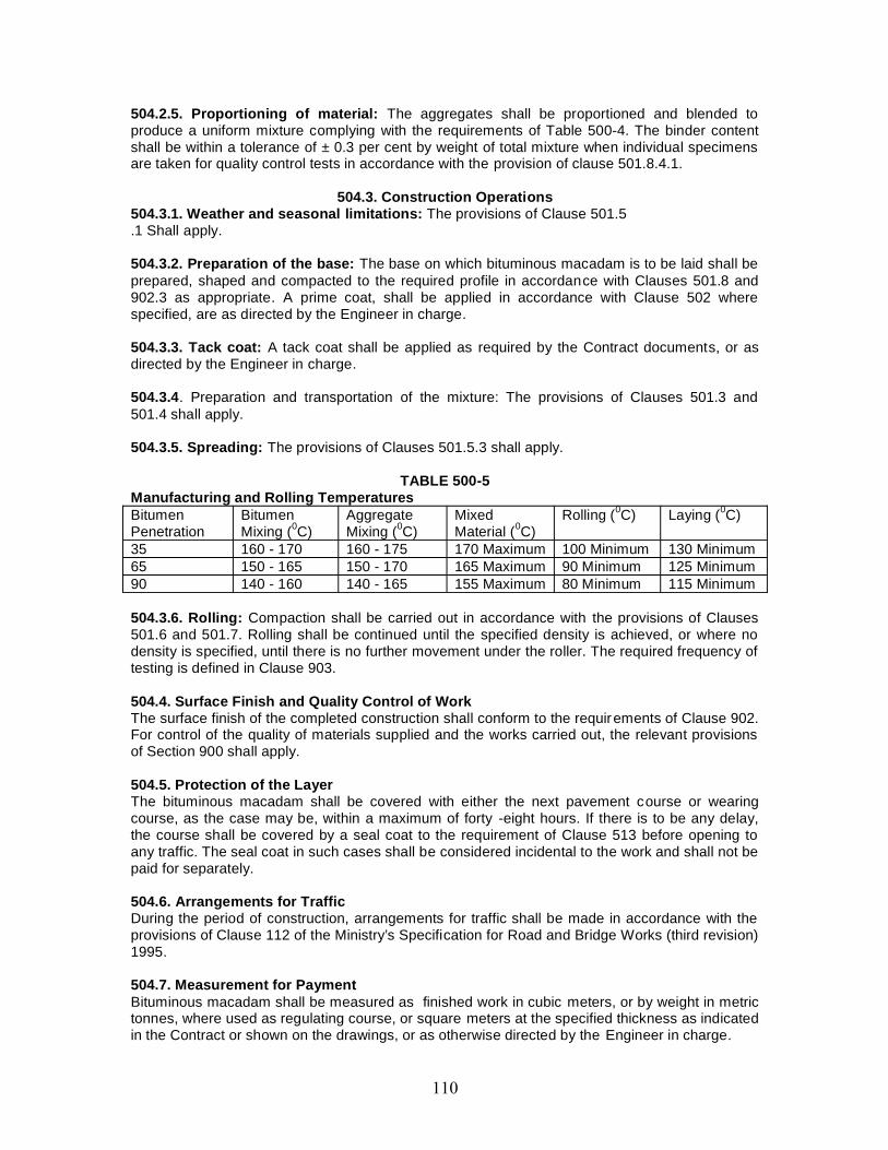
504.2.5. Proportioning of material: The aggregates shall be proportioned and blended toproduce a uniform mixture complying with the requirements of Table 500-4. The binder contentshall be within a tolerance of ± 0.3 per cent by weight of total mixture when individual specimensare taken for quality control tests in accordance with the provision of clause 501.8.4.1.
504.3. Construction Operations504.3.1. Weather and seasonal limitations: The provisions of Clause 501.5.1 Shall apply.
504.3.2. Preparation of the base: The base on which bituminous macadam is to be laid shall beprepared, shaped and compacted to the required profile in accordance with Clauses 501.8 and902.3 as appropriate. A prime coat, shall be applied in accordance with Clause 502 wherespecified, are as directed by the Engineer in charge.
504.3.3. Tack coat: A tack coat shall be applied as required by the Contract documents, or asdirected by the Engineer in charge.
504.3.4. Preparation and transportation of the mixture: The provisions of Clauses 501.3 and501.4 shall apply.
504.3.5. Spreading: The provisions of Clauses 501.5.3 shall apply.
TABLE 500-5Manufacturing and Rolling TemperaturesBitumenPenetration
BitumenMixing (0C)
AggregateMixing (0C)
MixedMaterial (0C)
Rolling (0C) Laying (0C)
35 160 - 170 160 - 175 170 Maximum 100 Minimum 130 Minimum65 150 - 165 150 - 170 165 Maximum 90 Minimum 125 Minimum90 140 - 160 140 - 165 155 Maximum 80 Minimum 115 Minimum
504.3.6. Rolling: Compaction shall be carried out in accordance with the provisions of Clauses501.6 and 501.7. Rolling shall be continued until the specified density is achieved, or where nodensity is specified, until there is no further movement under the roller. The required frequency oftesting is defined in Clause 903.
504.4. Surface Finish and Quality Control of WorkThe surface finish of the completed construction shall conform to the requirements of Clause 902.For control of the quality of materials supplied and the works carried out, the relevant provisionsof Section 900 shall apply.
504.5. Protection of the LayerThe bituminous macadam shall be covered with either the next pavement course or wearingcourse, as the case may be, within a maximum of forty -eight hours. If there is to be any delay,the course shall be covered by a seal coat to the requirement of Clause 513 before opening toany traffic. The seal coat in such cases shall be considered incidental to the work and shall not bepaid for separately.
504.6. Arrangements for TrafficDuring the period of construction, arrangements for traffic shall be made in accordance with theprovisions of Clause 112 of the Ministry’s Specification for Road and Bridge Works (third revision)1995.
504.7. Measurement for PaymentBituminous macadam shall be measured as finished work in cubic meters, or by weight in metrictonnes, where used as regulating course, or square meters at the specified thickness as indicatedin the Contract or shown on the drawings, or as otherwise directed by the Engineer in charge.
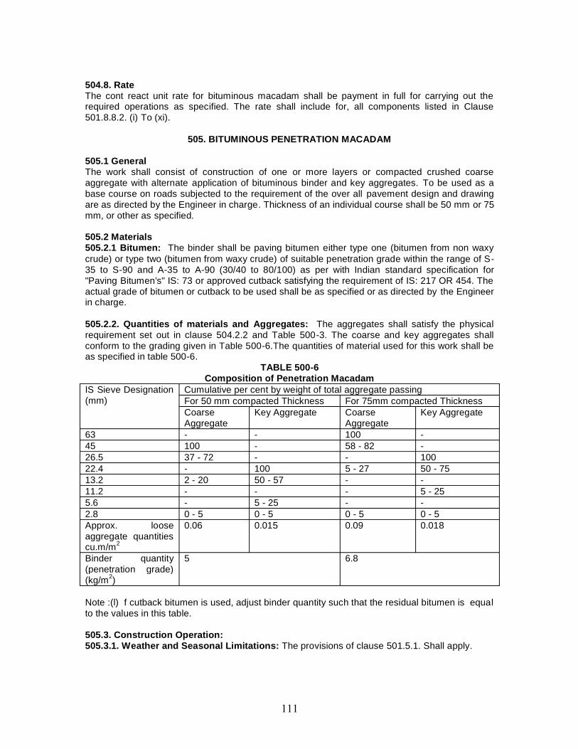
504.8. RateThe cont react unit rate for bituminous macadam shall be payment in full for carrying out therequired operations as specified. The rate shall include for, all components listed in Clause501.8.8.2. (i) To (xi).
505. BITUMINOUS PENETRATION MACADAM
505.1 GeneralThe work shall consist of construction of one or more layers or compacted crushed coarseaggregate with alternate application of bituminous binder and key aggregates. To be used as abase course on roads subjected to the requirement of the over all pavement design and drawingare as directed by the Engineer in charge. Thickness of an individual course shall be 50 mm or 75mm, or other as specified.
505.2 Materials505.2.1 Bitumen: The binder shall be paving bitumen either type one (bitumen from non waxycrude) or type two (bitumen from waxy crude) of suitable penetration grade within the range of S-35 to S-90 and A-35 to A-90 (30/40 to 80/100) as per with Indian standard specification for"Paving Bitumen’s" IS: 73 or approved cutback satisfying the requirement of IS: 217 OR 454. Theactual grade of bitumen or cutback to be used shall be as specified or as directed by the Engineerin charge.
505.2.2. Quantities of materials and Aggregates: The aggregates shall satisfy the physicalrequirement set out in clause 504.2.2 and Table 500-3. The coarse and key aggregates shallconform to the grading given in Table 500-6.The quantities of material used for this work shall beas specified in table 500-6.
TABLE 500-6Composition of Penetration Macadam
IS Sieve Designation(mm)
Cumulative per cent by weight of total aggregate passingFor 50 mm compacted Thickness For 75mm compacted ThicknessCoarseAggregate
Key Aggregate CoarseAggregate
Key Aggregate
63 - - 100 -45 100 - 58 - 82 -26.5 37 - 72 - - 10022.4 - 100 5 - 27 50 - 7513.2 2 - 20 50 - 57 - -11.2 - - - 5 - 255.6 - 5 - 25 - -2.8 0 - 5 0 - 5 0 - 5 0 - 5Approx. looseaggregate quantitiescu.m/m2
0.06 0.015 0.09 0.018
Binder quantity(penetration grade)(kg/m2)
5 6.8
Note :(l) f cutback bitumen is used, adjust binder quantity such that the residual bitumen is equalto the values in this table.
505.3. Construction Operation:505.3.1. Weather and Seasonal Limitations: The provisions of clause 501.5.1. Shall apply.

505.3.2 Equipment : A mechanical broom, compressor, self propelled or trailed bitumenheater/distributor, mechanical aggregates spreader and 8 to 10 tonnes smooth steel wheel rolleror vibrating roller are required for the preparation of penetration macadam.
505.3.3 Preparation of the base: same as per clause 504.3.2 and 504.3.3.
505.3.4. Spreading coarse aggregates:(i)The coarse aggregate shall be dry and clean and free from dust, and shall be spread uniformlyand evenly at the rate specified in Table 500-6.(ii)It shall be spread by a self- propelled or tipper tail mounted aggregate spreader capable ofspreading aggregate uniformly at the specified rates over the required widths.(iii)The surface of the layer shall be carefully checked with camber templates to ensure correctline and level and cross fall.(iv)The spreading shall be carried out such that the rolling and penetrating operations can becompleted on the same day.(v)Segregated aggregates or aggregates contaminated with foreign material shall be removedand replaced.
505.3.5. Compaction: After the spreading of coarse aggregates, dry rolling shall be carried outwith an 8 — 10 tonne smooth steel wheel roller. The requirements given in Clause 501.6 and501.7 shall apply. After initial dry rolling, the surface shall be checked with a crown template anda 3 meter straight-edge. The surface shall not vary more than 10 mm from die template orstraight-edge. All surface irregularities exceeding the above limit shall be corrected by removingor adding aggregates as required. The rolling shall continue until the compacted coarseaggregate has a firm surface true to the cross section shown on the plans and has a texture thatwill allow free and uniform penetration of the bituminous material.
505.3.6. Application of bituminous material: After the coarse aggregate has been rolled andchecked, the bituminous binder shall be applied, at the rate given in Table 500-6, in accordancewith Clause SOI, and at a temperature directed by the Engineer in charge. At the time of applyingthe binder, the aggregates shall be surface dry for the full depth of the layer.
505.3.7. Application of key aggregates: The key aggregate shall be clean dry and free fromdust. Immediately after the first application of bitumen, the key aggregates shall be spreaduniformly over the surface by means of an approved mechanical spreader or by approved manualmethods at the rate specified in Table 500-6. Where directed by the Engineer in charge, thesurface shall be swept and the quantity of key aggregate adjusted to ensure uniform application,with all the surface voids in the coarse aggregate being filled without excess. The entire surfaceshall then be rolled with a 8 - 10 tonnes smooth steel wheel roller (or vibrating roller operating innon -vibratory mode) in accordance with the procedure specified in Clause 505.3.5.
505.4. Surface Finish and Quality ControlThe surface finish of the completed construction shall conform to the requirements of Clause 902.For control of the quality of materials supplied and the works carried out the relevant provisions ofSection 900 shall apply.
505.5. SurfacingThe Penetration Macadam shall be provided with a surfacing (binder/ wearing course) within amaximum of forty-eight hours. If there is to be any delay, the penetration macadam shall becovered by a seal coat before opening to traffic. The seal coat in such cases shall be consideredincidental to the work and shall not be paid for separately.
505.6. Arrangements for TrafficDuring the period of construction, arrangements for traffic shall be made as directed by theEngineer in charge.
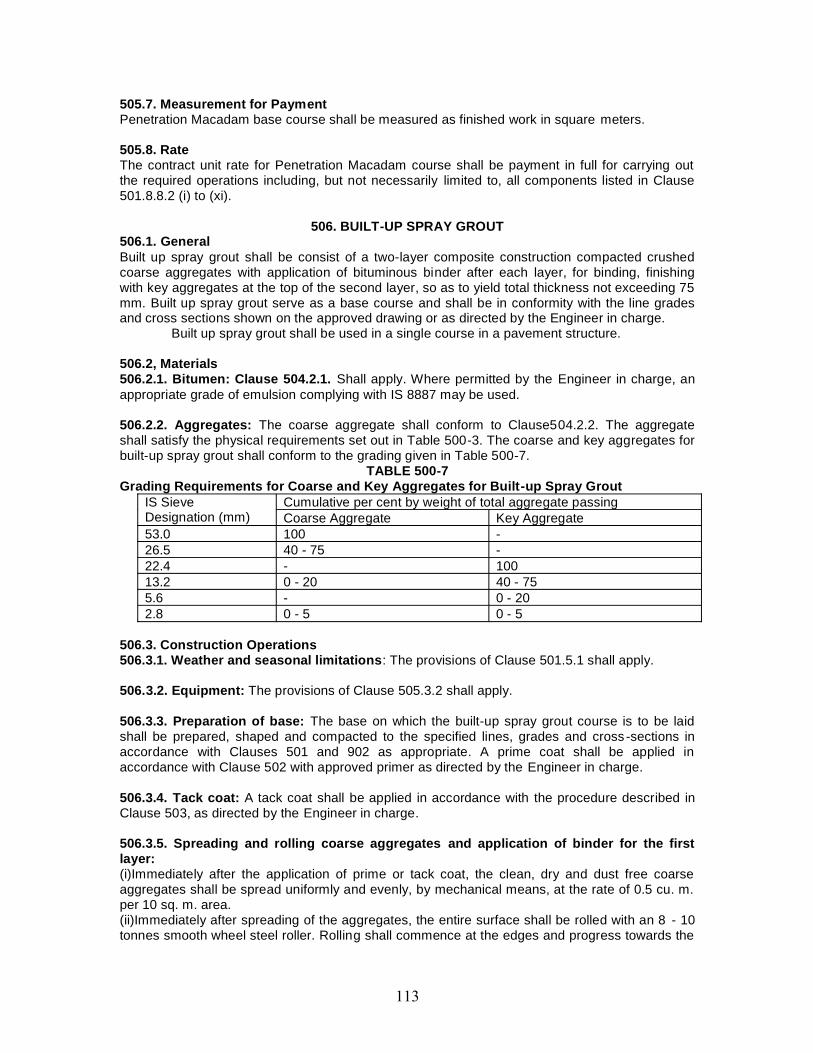
505.7. Measurement for PaymentPenetration Macadam base course shall be measured as finished work in square meters.
505.8. RateThe contract unit rate for Penetration Macadam course shall be payment in full for carrying outthe required operations including, but not necessarily limited to, all components listed in Clause501.8.8.2 (i) to (xi).
506. BUILT-UP SPRAY GROUT506.1. GeneralBuilt up spray grout shall be consist of a two-layer composite construction compacted crushedcoarse aggregates with application of bituminous binder after each layer, for binding, finishingwith key aggregates at the top of the second layer, so as to yield total thickness not exceeding 75mm. Built up spray grout serve as a base course and shall be in conformity with the line gradesand cross sections shown on the approved drawing or as directed by the Engineer in charge.
Built up spray grout shall be used in a single course in a pavement structure.
506.2, Materials506.2.1. Bitumen: Clause 504.2.1. Shall apply. Where permitted by the Engineer in charge, anappropriate grade of emulsion complying with IS 8887 may be used.
506.2.2. Aggregates: The coarse aggregate shall conform to Clause504.2.2. The aggregateshall satisfy the physical requirements set out in Table 500-3. The coarse and key aggregates forbuilt-up spray grout shall conform to the grading given in Table 500-7.
TABLE 500-7Grading Requirements for Coarse and Key Aggregates for Built-up Spray Grout
IS SieveDesignation (mm)
Cumulative per cent by weight of total aggregate passingCoarse Aggregate Key Aggregate
53.0 100 -26.5 40 - 75 -22.4 - 10013.2 0 - 20 40 - 755.6 - 0 - 202.8 0 - 5 0 - 5
506.3. Construction Operations506.3.1. Weather and seasonal limitations: The provisions of Clause 501.5.1 shall apply.
506.3.2. Equipment: The provisions of Clause 505.3.2 shall apply.
506.3.3. Preparation of base: The base on which the built-up spray grout course is to be laidshall be prepared, shaped and compacted to the specified lines, grades and cross -sections inaccordance with Clauses 501 and 902 as appropriate. A prime coat shall be applied inaccordance with Clause 502 with approved primer as directed by the Engineer in charge.
506.3.4. Tack coat: A tack coat shall be applied in accordance with the procedure described inClause 503, as directed by the Engineer in charge.
506.3.5. Spreading and rolling coarse aggregates and application of binder for the firstlayer:(i)Immediately after the application of prime or tack coat, the clean, dry and dust free coarseaggregates shall be spread uniformly and evenly, by mechanical means, at the rate of 0.5 cu. m.per 10 sq. m. area.(ii)Immediately after spreading of the aggregates, the entire surface shall be rolled with an 8 - 10tonnes smooth wheel steel roller. Rolling shall commence at the edges and progress towards the
centre except in super elevated and uni-directional cambered portions where it shall proceed fromthe lower edge to the higher edge.(iii)Each pass of the roller shall uniformly overlap not less than one-third of the track made in thepreceding pass.(iv)The surface of the layer shall be carefully checked, after rolling, with a template and straightedge and shall be within the tolerances specified, and any deficiencies corrected by reworkingand recomposing the layer.(v)Care shall be taken not to over compact the layer.(vi) The binder shall be heated to the temperature appropriate to the grade of bitumen approvedby the Engineer in charge and sprayed on the aggregate at the rate of IS kg15kg/10 sq. m.(measured in terms of residual bitumen content) at a uniform rate of spray by mechanicalsprayers capable of spraying bitumen uniformly at the specified rates and temperatures.(vii)Excessive deposits of binder caused by stopping or starting of the sprayers or throughleakage or for any other reason shall be removed and made good.
506.3.6. Spreading and rolling of coarse aggregate and application of binder for thesecond layer:(i)Immediately after the first application of the binder, the second layer of coarse aggregates shallbe spread and rolled in accordance with the procedure detailed in Clause 506.3.5.(ii)The second aggregate layer shall then be sprayed with binder at the rate of 15 kg/10 sq. m.(measured in terms of residual bitumen content) in accordance with Clause 506.3.6.
506.3.7. Application of key aggregate:(i)Immediately after the second application of binder, key aggregates shall be spread uniformlyand evenly, preferably by mechanical means, at the rate of 0.13 cu.m. /10 sqm. (ii)So as to coverthe surface completely. The key aggregate shall be clean, dry and free from dust and deleteriousmatter.(iii)If necessary, the surface shall be swept to ensure uniform application of the key aggregates.The entire surface shall then be rolled with an 8-10 tonnes smooth wheel steel roller inaccordance with Clause 506.3.5.(iv)While rolling is in progress, additional key aggregates, where required, shall be spread byhand. Rolling shall continue-until the entire course is thoroughly compacted and the keyaggregates are firmly in position.
506.4. Surface Finish and Quality ControlThe surface finish of construction shall conform to the requirements of Clause 902. All materialsshall comply with the requirements of the relevant provisions in Section 900 of the Specifications.
506.5. Final SurfacingThe built-up-spray-grout shall be provided with final surfacing within a maximum of forty -sighthours. If there is to be any delay, the course shall be covered by a seal coat to the requirem ent ofClause 513 before it is open to traffic. Where the seal coat is required as a result of the selectedmethod of performing this operation, then it shall be considered incidental to the work and shallnot be paid for separately.
506.6. Arrangements for TrafficDuring the period of construction, arrangements for traffic shall be made in accordance with theprovisions of Clause 112 of the Ministry’s Specification for Road and Bridge Works (third revision)1995.
506.7. Measurement for PaymentBuilt-up spray grout shall be measured as finished work in square meters.
506.8. Rate
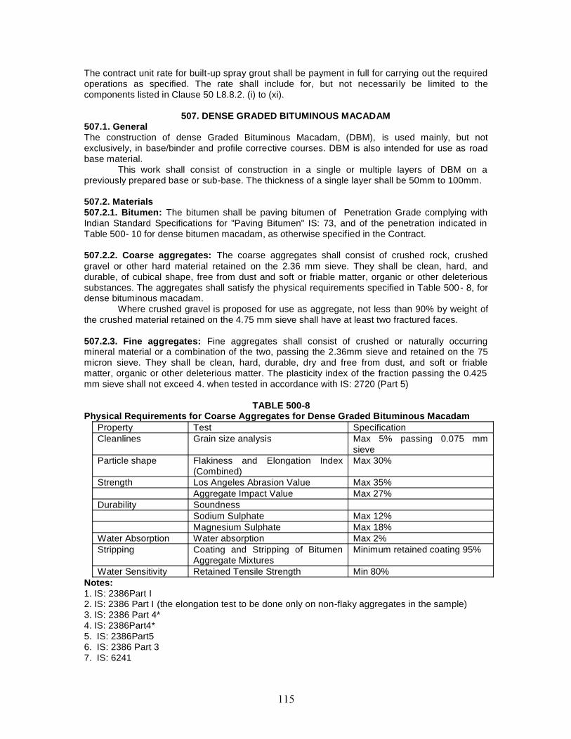
The contract unit rate for built-up spray grout shall be payment in full for carrying out the requiredoperations as specified. The rate shall include for, but not necessari ly be limited to thecomponents listed in Clause 50 L8.8.2. (i) to (xi).
507. DENSE GRADED BITUMINOUS MACADAM507.1. GeneralThe construction of dense Graded Bituminous Macadam, (DBM), is used mainly, but notexclusively, in base/binder and profile corrective courses. DBM is also intended for use as roadbase material.
This work shall consist of construction in a single or multiple layers of DBM on apreviously prepared base or sub-base. The thickness of a single layer shall be 50mm to 100mm.
507.2. Materials507.2.1. Bitumen: The bitumen shall be paving bitumen of Penetration Grade complying withIndian Standard Specifications for "Paving Bitumen" IS: 73, and of the penetration indicated inTable 500- 10 for dense bitumen macadam, as otherwise specif ied in the Contract.
507.2.2. Coarse aggregates: The coarse aggregates shall consist of crushed rock, crushedgravel or other hard material retained on the 2.36 mm sieve. They shall be clean, hard, anddurable, of cubical shape, free from dust and soft or friable matter, organic or other deleterioussubstances. The aggregates shall satisfy the physical requirements specified in Table 500- 8, fordense bituminous macadam.
Where crushed gravel is proposed for use as aggregate, not less than 90% by weight ofthe crushed material retained on the 4.75 mm sieve shall have at least two fractured faces.
507.2.3. Fine aggregates: Fine aggregates shall consist of crushed or naturally occurringmineral material or a combination of the two, passing the 2.36mm sieve and retained on the 75micron sieve. They shall be clean, hard, durable, dry and free from dust, and soft or friablematter, organic or other deleterious matter. The plasticity index of the fraction passing the 0.425mm sieve shall not exceed 4. when tested in accordance with IS: 2720 (Part 5)
TABLE 500-8Physical Requirements for Coarse Aggregates for Dense Graded Bituminous Macadam
Property Test SpecificationCleanlines Grain size analysis Max 5% passing 0.075 mm
sieveParticle shape Flakiness and Elongation Index
(Combined)Max 30%
Strength Los Angeles Abrasion Value Max 35%Aggregate Impact Value Max 27%
Durability SoundnessSodium Sulphate Max 12%Magnesium Sulphate Max 18%
Water Absorption Water absorption Max 2%Stripping Coating and Stripping of Bitumen
Aggregate MixturesMinimum retained coating 95%
Water Sensitivity Retained Tensile Strength Min 80%Notes:1. IS: 2386Part I2. IS: 2386 Part I (the elongation test to be done only on non-flaky aggregates in the sample)3. IS: 2386 Part 4*4. IS: 2386Part4*5. IS: 2386Part56. IS: 2386 Part 37. IS: 6241

8. AASHTOT283* Aggregate may satisfy requirements of either of these two tests.** The water sensitivity test is only required if the minimum retained coating in the stripping lestis less than 95%.
507.2.4. Filler: Filler shall consist of finely divided mineral matter such as rock dust, hydratedlime or cement approved by the Engineer in charge. The filler shall be graded within the limitsindicated in Table 500-9.
TABLE 500-9Grading Requirements for Mineral Filler
IS Sieve (mm) Cumulative per cent passing by weight of totalaggregate
0.6 1000.3 95 - 1000.075 85 - 100
The filler shall be free from organic impurities and have a Plasticity Index not greater than 4. ThePlasticity Index requirement shall not apply if filler is cement or lime. When the coarse aggregateis gravel, 2 per cent by weight of total aggregate, shall be Portland cement or hydrated lime andthe percentage of fine aggregate reduced accordingly. Cement or hydrated lime is not requiredwhen the limestone aggregate is used. Where the aggregates fail to meet the requirements of thewater sensitivity test in Table 500-8, then 2 per cent by total weight of aggregate, of hydrated limeshall be added without additional cost.
507.2.5. Aggregate grading and binder content: When tested in accordance with IS:2386 Part1 (wet sieving method), the combined grading of the coarse and fine aggregates and added fillerfor the particular mixture shall fall within the limits shown in Table 500-10, for dense bituminousmacadam grading 1 or 2 as specified in the Contract. The type and quantity of bitumen, andappropriate thickness, are also indicated for each mixture type.
TABLE 500-10Composition of Dense Graded Bituminous Macadam Pavement Layers
Grading 1 2Nominal aggregate size 40 mm 25 mmLayer Thickness 80 - 100 mm 50 - 75 mmIS Sieve (mm) Cumulative % by weight of total aggregate passing45 10037.5 95 - 100 10026.5 63 - 93 90 - 10019 - 71 - 9513.2 55 - 75 56 - 809.5 - -4.75 38 - 54 38 - 542.36 28 - 42 28 - 421.18 - -0.6 - -0.3 7 - 21 7 - 210.15 - -0.075 2 - 8 2 - 8Bitumen content % bymass of total mix2 Min 4.0 Min 4.5Bitumen grade (pen) 65 or 90 65 or 90
Notes: 1. The combined aggregate grading shall not vary from the low limit on one sieve to thehigh limit on the adjacent sieve.2. Determined by the Marshall method.
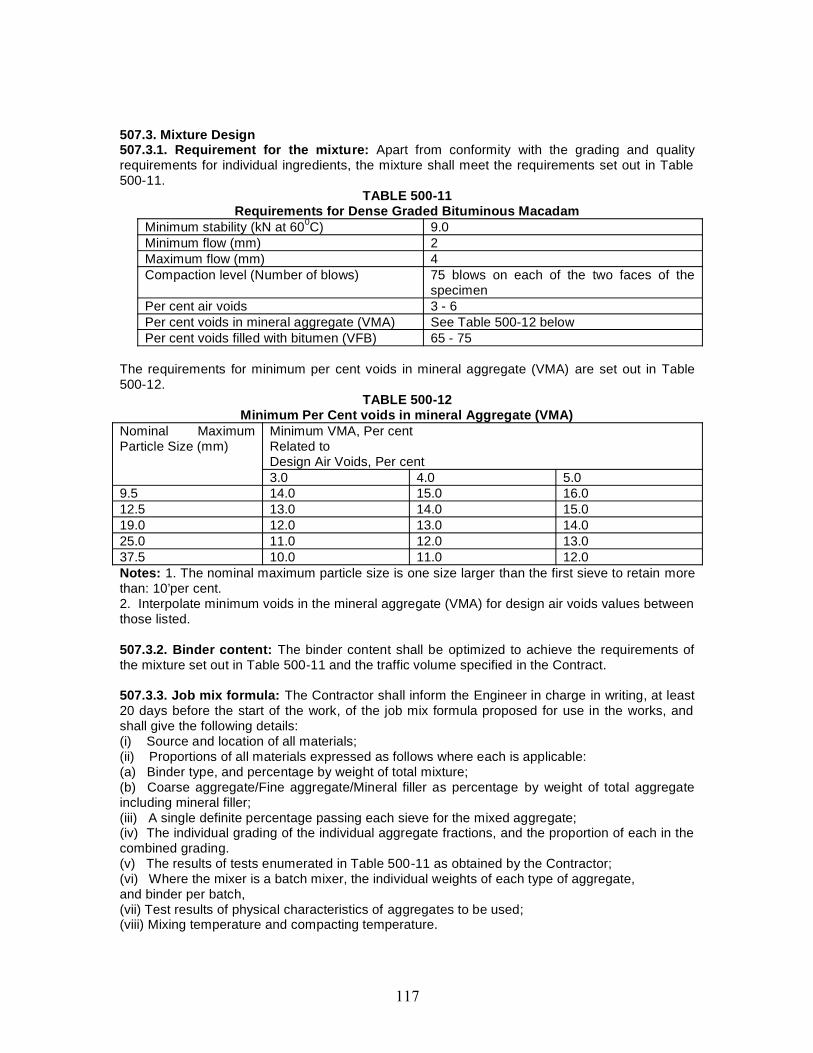
507.3. Mixture Design507.3.1. Requirement for the mixture: Apart from conformity with the grading and qualityrequirements for individual ingredients, the mixture shall meet the requirements set out in Table500-11.
TABLE 500-11Requirements for Dense Graded Bituminous Macadam
Minimum stability (kN at 600C) 9.0Minimum flow (mm) 2Maximum flow (mm) 4Compaction level (Number of blows) 75 blows on each of the two faces of the
specimenPer cent air voids 3 - 6Per cent voids in mineral aggregate (VMA) See Table 500-12 belowPer cent voids filled with bitumen (VFB) 65 - 75
The requirements for minimum per cent voids in mineral aggregate (VMA) are set out in Table500-12.
TABLE 500-12Minimum Per Cent voids in mineral Aggregate (VMA)
Nominal MaximumParticle Size (mm)
Minimum VMA, Per centRelated toDesign Air Voids, Per cent3.0 4.0 5.0
9.5 14.0 15.0 16.012.5 13.0 14.0 15.019.0 12.0 13.0 14.025.0 11.0 12.0 13.037.5 10.0 11.0 12.0Notes: 1. The nominal maximum particle size is one size larger than the first sieve to retain morethan: 10’per cent.2. Interpolate minimum voids in the mineral aggregate (VMA) for design air voids values betweenthose listed.
507.3.2. Binder content: The binder content shall be optimized to achieve the requirements ofthe mixture set out in Table 500-11 and the traffic volume specified in the Contract.
507.3.3. Job mix formula: The Contractor shall inform the Engineer in charge in writing, at least20 days before the start of the work, of the job mix formula proposed for use in the works, andshall give the following details:(i) Source and location of all materials;(ii) Proportions of all materials expressed as follows where each is applicable:(a) Binder type, and percentage by weight of total mixture;(b) Coarse aggregate/Fine aggregate/Mineral filler as percentage by weight of total aggregateincluding mineral filler;(iii) A single definite percentage passing each sieve for the mixed aggregate;(iv) The individual grading of the individual aggregate fractions, and the proportion of each in thecombined grading.(v) The results of tests enumerated in Table 500-11 as obtained by the Contractor;(vi) Where the mixer is a batch mixer, the individual weights of each type of aggregate,and binder per batch,(vii) Test results of physical characteristics of aggregates to be used;(viii) Mixing temperature and compacting temperature.
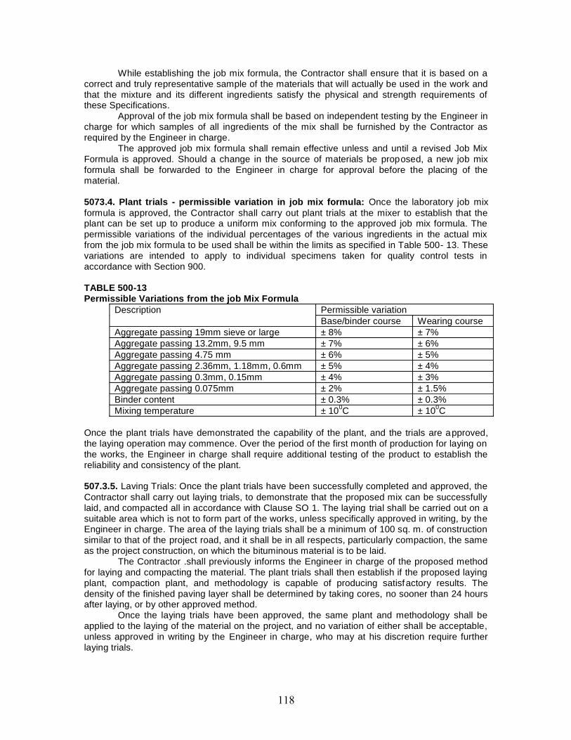
While establishing the job mix formula, the Contractor shall ensure that it is based on acorrect and truly representative sample of the materials that will actually be used in the work andthat the mixture and its different ingredients satisfy the physical and strength requirements ofthese Specifications.
Approval of the job mix formula shall be based on independent testing by the Engineer incharge for which samples of all ingredients of the mix shall be furnished by the Contractor asrequired by the Engineer in charge.
The approved job mix formula shall remain effective unless and until a revised Job MixFormula is approved. Should a change in the source of materials be proposed, a new job mixformula shall be forwarded to the Engineer in charge for approval before the placing of thematerial.
5073.4. Plant trials - permissible variation in job mix formula: Once the laboratory job mixformula is approved, the Contractor shall carry out plant trials at the mixer to establish that theplant can be set up to produce a uniform mix conforming to the approved job mix formula. Thepermissible variations of the individual percentages of the various ingredients in the actual mixfrom the job mix formula to be used shall be within the limits as specified in Table 500- 13. Thesevariations are intended to apply to individual specimens taken for quality control tests inaccordance with Section 900.
TABLE 500-13Permissible Variations from the job Mix Formula
Description Permissible variationBase/binder course Wearing course
Aggregate passing 19mm sieve or large ± 8% ± 7%Aggregate passing 13.2mm, 9.5 mm ± 7% ± 6%Aggregate passing 4.75 mm ± 6% ± 5%Aggregate passing 2.36mm, 1.18mm, 0.6mm ± 5% ± 4%Aggregate passing 0.3mm, 0.15mm ± 4% ± 3%Aggregate passing 0.075mm ± 2% ± 1.5%Binder content ± 0.3% ± 0.3%Mixing temperature ± 100C ± 100C
Once the plant trials have demonstrated the capability of the plant, and the trials are approved,the laying operation may commence. Over the period of the first month of production for laying onthe works, the Engineer in charge shall require additional testing of the product to establish thereliability and consistency of the plant.
507.3.5. Laving Trials: Once the plant trials have been successfully completed and approved, theContractor shall carry out laying trials, to demonstrate that the proposed mix can be successfullylaid, and compacted all in accordance with Clause SO 1. The laying trial shall be carried out on asuitable area which is not to form part of the works, unless specifically approved in writing, by theEngineer in charge. The area of the laying trials shall be a minimum of 100 sq. m. of constructionsimilar to that of the project road, and it shall be in all respects, particularly compaction, the sameas the project construction, on which the bituminous material is to be laid.
The Contractor .shall previously informs the Engineer in charge of the proposed methodfor laying and compacting the material. The plant trials shall then establish if the proposed layingplant, compaction plant, and methodology is capable of producing satisfactory results. Thedensity of the finished paving layer shall be determined by taking cores, no sooner than 24 hoursafter laying, or by other approved method.
Once the laying trials have been approved, the same plant and methodology shall beapplied to the laying of the material on the project, and no variation of either shall be acceptable,unless approved in writing by the Engineer in charge, who may at his discretion require furtherlaying trials.

507.4. Construction Operations507.4.1. Weather and seasonal limitations: The provisions of Clause 501.5.1 shall apply.
507.4.2. Preparation of base:(i)The base on which Dense Graded Bituminous Material is to be laid shall be prepared inaccordance with Clauses 501 and 902 as appropriate, or as directed by the Engineer in charge.(ii)The surface shall be thoroughly swept clean by a mechanical broom, and the dust removed bycompressed air. In locations where-mechanical broom cannot access, other approved methodsshall be used as directed by the Engineer in charge.
507.4.3. Geosynthetics and Stress absorbing layer:(a)Where Geosynthetics are specified in the Contract this shall be in accordance with therequirements stated in Clause 70 3.(b)Where a stress absorbing layer is specified in the Contract, this shall be applied in accordancewith the requirements of Clause 522.
507.4.4. Prime coat: Where the material on which the dense bituminous macadam is to be laid isother than a bitumen bound layer, a prime coat shall be applied, as specified, in accordance withthe provisions of Clause 502, or as directed by the Engineer in charge.
507.4.5. Tack coat: Where the material on which the dense bituminous macadam is to be placedis bitumen bound surface, a tack coat shall be applied as specified, in accordance with theprovisions of Clause 503, or as directed by the Engineer in charge.
507.4.6. Mixing and transportation of the mixture: The provisions as specified in Clauses501.3 and 501.4 shall apply.
507.4.7. Spreading: The provisions of Clauses 501.5.3 and 501.5.4. Shall apply.
507.4.8. Rolling: The general provisions of Clauses 501.6 and 501.7 shall apply, as modified bythe approved laying trials. The compaction process shall be carried out by the same plant, andusing the same method, as approved in the laying trials, which may be varied only with theexpress approval of the Engineer in charge in writing.
507.5. Opening to TrafficThe newly laid surface shall not be open to traffic for at least 24 hrs after laying and completion ofcompaction, without the express approval of the Engineer in charge in writing.
507.6. Surface Finish and Quality Control of WorkThe surface finish; of the completed construction shall conform to the requirements of Clause902. All materials and workmanship shall comply with the provisions set out in Section 900 of thisSpecification.
507.7. Arrangements for TrafficDuring the period of construction, arrangements for traffic shall be made as per directionEngineer in charge.
507.8. Measurement for PaymentDense Graded Bituminous Materials shall be measured as finished work either in cubic meters,tons or by the square meter at a specified thickness as detailed on the Contract drawings, ordocuments, and in as directed by the Engineer in charge.
507.9. RateThe contract unit rate for Dense Graded Bituminous Macadam shall be payment in full forcarrying out the all required operations as specified, and shall include, but not necessarily limited

to all components listed in Clause 501.8 8.2 (i) to (xi). The rate shall include the provision ofbitumen, at 4.25 per cent by weight of the total mixture.
The variance in actual percentage of bitumen used will be assessed and the paymentadjusted, up or down, accordingly.
508. SEMI-DENSE BITUMINOUS CONCRETE508.1. General(i)The construction of Semi Dense Bituminous Concrete is used in wearing/binder and profilecorrective courses.(ii)This work shall consist of construction in a single or multiple layers of semi dense bituminousconcrete on a previously prepared bituminous bound surface.(iii)A single layer of semi dense bituminous concrete shall be 25mm to 100mm in thickness.
508.2. Materials508.2.1. Bitumen: The bitumen shall be paving bitumen of Penetration grade complying withIndian Standard Specification for Paving Bitumen, IS: 73 and of the penetration indicated in Table500-15, for semi dense bituminous concrete, or as otherwise specified in the Contract.
508.2.2. Coarse aggregates: The coarse aggregates shall be generally as specified in Clause507.2.2, except that the aggregates shall satisfy the physical requirements of Table 500-14.
508.2.3. Fine aggregates: The fine aggregates shall be all as specified in Clause 507.2.3.
508.2.4. Filler: Filler shall, be generally as specified in Clause 507.2.4. Where the aggregates failto meet the requirements of the water sensitivity test in Table 500-14 then 2 per cent by totalweight of aggregate, of hydrated lime shall be added without additional cost.
508.2.5. Aggregate grading and binder content: When tested in accordance with IS: 2386 Part1 (Wet sieving method), the combined grading of the coarse and fine aggregates and added fillershall fall within the limits shown in Table 500-15 for grading 1 or 2 as specified in the Contract.
508.3. Mixture Design508.3.1. Requirements for the mixture: Apart from conformity with the grading and qualityrequirements for individual ingredients the mixture shall meet the requirements set out in Table500-16.
TABLE 500-14Physical Requirements for Coarse Aggregates for Semi Dense Bituminous Concrete
Pavement LayersProperty Test SpecificationCleanliness (dust) Grain size analysis Max 5% passing 0.075 mm
sieveParticle shape Flakiness and Elongation Index
(Combined)Max 30%
Strength Los Angeles Abrasion Value Max 35%Aggregate Impact Value Max 27%
Polishing Polished Stone Value Min 55Durability Soundness
Sodium Sulphate Max 12%Magnesium Sulphate Max 18%
Water Absorption Water absorption Max 2%Stripping Coating and Stripping of Bitumen
Aggregate MixturesMinimum retained coating 95%
Water Sensitivity Retained Tensile Strength Min 80%
Notes:
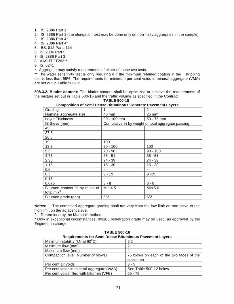
1. IS: 2386 Part 12. IS: 2386 Part 1 (the elongation test may be done only on non-flaky aggregates in the sample)3. IS: 2386 Part 4*4. IS: 2386 Part 4*5. BS: 812 Parts 1146. IS: 2386 Part 57. IS: 2386 Part 38. AASHTOT283**9. IS: 6241* Aggregate may satisfy requirements of either of these two tests.** The water sensitivity test is only requiring d if the minimum retained coating in the strippingtest is less than 95%. The requirements for minimum per cent voids in mineral aggregate (VMA)are set out in Table 500-12.
508.3.2. Binder content: The binder content shall be optimized to achieve the requirements ofthe mixture set out in Table 500-16 and the traffic volume as specified in the Contract.
TABLE 500-15Composition of Semi Dense Bituminous Concrete Pavement Layers
Grading 1 2Nominal aggregate size 40 mm 25 mmLayer Thickness 80 - 100 mm 50 - 75 mmIS Sieve (mm) Cumulative % by weight of total aggregate passing4537.526.519 10013.2 90 - 100 1009.5 70 - 90 90 - 1004.75 35 - 51 35 - 512.36 24 - 39 24 - 391.18 15 - 30 15 - 300.6 - -0.3 9 - 19 9 -190.15 - -0.075 3 - 8 3 - 8Bitumen content % by mass oftotal mix2
Min 4.5 Min 5.0
Bitumen grade (pen) 65* 65*
Notes: 1. The combined aggregate grading shall not vary from the low limit on one sieve to thehigh limit on the adjacent sieve.2. Determined by the Marshall method.* Only in exceptional circumstances, 80/100 penetration grade may be used, as approved by theEngineer in charge.
TABLE 500-16Requirements for Semi Dense Bituminous Pavement Layers
Minimum stability (kN at 600C) 8.2Minimum flow (mm) 2Maximum flow (mm) 4Compaction level (Number of blows) 75 blows on each of the two faces of the
specimenPer cent air voids 3 - 5Per cent voids in mineral aggregate (VMA) See Table 500-12 belowPer cent voids filled with bitumen (VFB) 65 - 78
508.3.3. Job mix formula: The procedure for formulating the job mix formula shall be generallyas specified in Clause 507.3.3 and the results of tests enumerated in Table 500- 1 6 as obtainedby the Contractors.
508.3.4. Plant trials - permissible variation in job mix formula: The requirements for planttrials shall be alt as specified in Clause 507.3.4, and permissible limits for variation as shown inTable 500-13.
508-3.5. Laying trials: The requirements for laying trials shall be all as specified iii Clause507.3.5.
508.4. Construction Operations508.4.1. Weather and seasonal limitations: The provisions of Clause 501.5.1 shall apply.
508.4.2. Preparation of base:(i)The surface on which the Semi Dense Bituminous material is to be laid shall be prepared inaccordance with Clauses 501 and 902 as appropriate, or as directed by the Engineer in charge.(ii)The surface shall be thoroughly swept clean by mechanical broom and dust removed bycompressed air. In locations where a mechanical broom cannot access, other approved methodsshall be used as directed by the Engineer in charge.
508.4.3. Geosynthetics: Where Geosynthetics are specified in the Contract this shall be inaccordance with the requirements stated in Clause 704 of the Ministry’s Specification for Roadand Bridge Works (third revision) 1995.
508.4.4. Stress absorbing layer: Where a stress absorbing layer is specified in the Contract,this shall be applied in accordance with the requirements of Clause 522.
508.4.5. Tack coat: Where specified in the Contract, or otherwise required by the Engineer incharge, a tack coat shall be applied in accordance with the requirements ’of Clause 503.
508.4.6. Mixing and transportation of the mixture: The provisions as specified in Clauses 501.3. And 501.4 shall apply.
508.4.7. Spreading: The general provisions of Clauses 501.5.3 and 501.5.4 shall apply.
508.4.8. Rolling: The general provisions of Clauses 501.6 and 501.7 shall apply, as modified bythe approved laying trials. The compaction process shall be carried out by the same plant, andusing the same method, as approved in the laying trials, which may be varied only with theexpress approval of the Engineer in charge in writing.
508.5. Opening to TrafficThe newly laid surface shall not be open to traffic for at least 24 hours after laying and hecompletion of compaction, without the express approval of the Engineer in charge in writing.
508.6. Surface Finish and Quality ControlThe surface finish of the completed construction shall conform to the requirements of Clause 902.All materials and workmanship shall comply with the provisions set out in Section 900 of thisSpecification.
508.7. Arrangements for TrafficDuring the period of construction, arrangements for traffic shall be made as per directionEngineer in charge.

508.8. Measurement for PaymentThe measurement shall be all as specified in Clause 507.8. 508.9. Rate The contract unit rateshall be all as specified in Clause 5Q7.9, except that the rate shall include the provision ofbitumen at 4.75% by weight of total mixture. The variance in actual percentage of bitumen usedwill be assessed and the payment adjusted up or down, accordingly.
509. BITUMINOUS CONCRETE509.1. Scope(i)This clause specifies the construction of Bituminous Concrete, for use in wearing and profilecorrective courses.(ii)This work shall consist of construction in a single or multiple layers of bituminous concrete on apreviously prepared bituminous bound surface.(iii)A single layer of bituminous concrete shall be 25mm to 100mm in thickness.
509.2. Materials509.2.1. Bitumen: The bitumen shall be paving bitumen of Base and Surface Courses(Bituminous) Section 500 Penetration grade complying with Indian Standard Specification forPaving Bitumen, IS: 73 and of the penetration indicated in Table 500-18, for bituminous concrete,or as otherwise specified in the Contract. Guidance on the selection of an appropriate grade ofbitumen is given in The Manual for Construction and Supervision of Bituminous Works.
509.2.2. Coarse aggregates and Fine aggregates:(i)The coarse aggregates shall be generally as specified in Clause 507.2.2, except that theaggregates shall satisfy the physical requirements of Table 500-17.(ii)The fine aggregates shall be all as specified in Clause 507.2.3.
509.2.3. Filler: Filler shall be generally as specified in Clause 507.2.4. Where the aggregates failto meet the requirements of the water sensitivity test in Table 500-17 then 2 per cent by totalweight of aggregate, of hydrated lime shall be added without additional cost.
509.2.4. Aggregate grading and binder content: When tested in accordance with IS: 2386 Part1 (Wet grading method), the combined grading-of the coarse and fine aggregates and added fillershall fall within the limits shown in Table 500-18 for grading 1 or 2 as specified in the Contract.
509.3. Mixture Design5093.1. Requirements for the mixture: Apart from conformity with the grading and qualityrequirements for individual ingredients, the mixture shall meet the requirements set out in Table500-19.
The requirements for minimum per cent voids in mineral aggregate (VMA) are set out inTable 500-12.
509.3.2. Binder content: The binder content shall be optimized to achieve the requirements ofthe mixture set out in Table 500-19 and the traffic volume as specified in the Contract.
509.3.3. Job mix formula: The procedure for formulating the job
Physical Requirements for Coarse Aggregates for Bituminous Concrete Pavement LayersProperty Test SpecificationCleanliness (dust) Grain size analysis Max 5% passing 0.075 mm
sieveParticle shape Flakiness and Elongation Index Max 30%Strength Los Angeles Abrasion Value Max 35%
Aggregate Impact Value Max 27%Polishing Polished Stone Value Min 55Durability Soundness
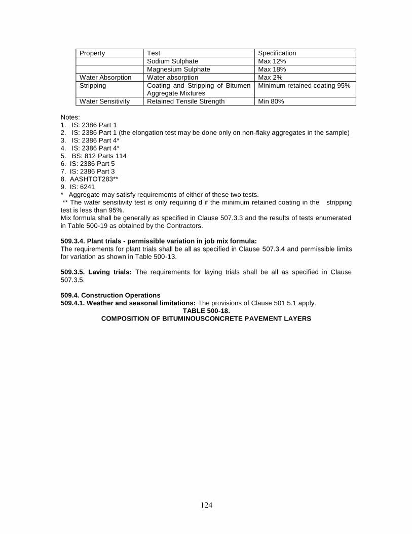
Property Test SpecificationSodium Sulphate Max 12%Magnesium Sulphate Max 18%
Water Absorption Water absorption Max 2%Stripping Coating and Stripping of Bitumen
Aggregate MixturesMinimum retained coating 95%
Water Sensitivity Retained Tensile Strength Min 80%
Notes:1. IS: 2386 Part 12. IS: 2386 Part 1 (the elongation test may be done only on non-flaky aggregates in the sample)3. IS: 2386 Part 4*4. IS: 2386 Part 4*5. BS: 812 Parts 1146. IS: 2386 Part 57. IS: 2386 Part 38. AASHTOT283**9. IS: 6241* Aggregate may satisfy requirements of either of these two tests.** The water sensitivity test is only requiring d if the minimum retained coating in the stripping
test is less than 95%.Mix formula shall be generally as specified in Clause 507.3.3 and the results of tests enumeratedin Table 500-19 as obtained by the Contractors.
509.3.4. Plant trials - permissible variation in job mix formula:The requirements for plant trials shall be all as specified in Clause 507.3.4 and permissible limitsfor variation as shown in Table 500-13.
509.3.5. Laving trials: The requirements for laying trials shall be all as specified in Clause507.3.5.
509.4. Construction Operations509.4.1. Weather and seasonal limitations: The provisions of Clause 501.5.1 apply.
TABLE 500-18.COMPOSITION OF BITUMINOUSCONCRETE PAVEMENT LAYERS
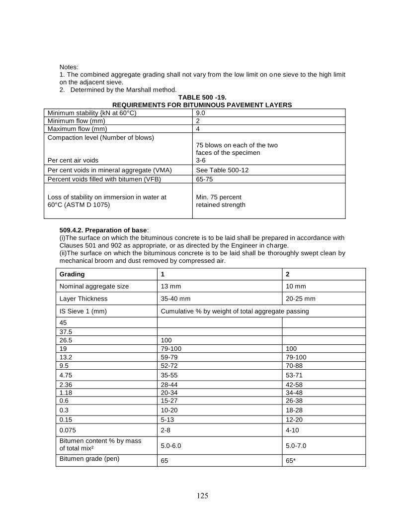
Notes:1. The combined aggregate grading shall not vary from the low limit on one sieve to the high limiton the adjacent sieve.2. Determined by the Marshall method.
TABLE 500 -19.REQUIREMENTS FOR BITUMINOUS PAVEMENT LAYERS
Minimum stability {kN at 60°C) 9.0Minimum flow (mm) 2Maximum flow (mm) 4Compaction level (Number of blows)
Per cent air voids
75 blows on each of the twofaces of the specimen3-6
Per cent voids in mineral aggregate (VMA) See Table 500-12Percent voids filled with bitumen (VFB) 65-75
Loss of stability on immersion in water at60°C (ASTM D 1075)
Min. 75 percentretained strength
509.4.2. Preparation of base:(i)The surface on which the bituminous concrete is to be laid shall be prepared in accordance withClauses 501 and 902 as appropriate, or as directed by the Engineer in charge.(ii)The surface on which the bituminous concrete is to be laid shall be thoroughly swept clean bymechanical broom and dust removed by compressed air.
Grading 1 2
Nominal aggregate size 13 mm 10 mm
Layer Thickness 35-40 mm 20-25 mm
IS Sieve 1 (mm) Cumulative % by weight of total aggregate passing
4537.526.5 10019 79-100 10013.2 59-79 79-1009.5 52-72 70-884.75 35-55 53-712.36 28-44 42-581.18 20-34 34-480.6 15-27 26-380.3 10-20 18-280.15 5-13 12-200.075 2-8 4-10Bitumen content % by massof total mix² 5.0-6.0 5.0-7.0
Bitumen grade (pen) 65 65*
(iii)In locations where a mechanical broom cannot access other approved methods shall be usedas directed by the Engineer in charge.
509.4.3. Geosynthetics: Where Geosynthetics are specified in the Contract this shall be inaccordance with the requirements stated in Clause 704 of the Ministry’s Specification for Roadand Bridge Works (third revision) 1995.
509.4.4. Stress absorbing layer. Where a stress absorbing layer is specified in the Contract, thisshall be applied in accordance- with the requirements of Clause 522.
509.4.5. Tack coat: Where specified in the Contract, or otherwise required by the Engineer incharge, a tack coat shall be applied in accordance with the requirements of Clause 503.
509.4.6. Mixing and transportation of the mixture: The provisions as specified in Clauses501.3 and 501.4 shall apply.
509.4.7. Spreading: The general provisions of clauses 501.5.3 and 501.5.4 shall apply.
509.4.8. Rolling: The general provisions of clauses 501.6 and 501.7 shall apply, as modified bythe approved laying trials.
509.5. Opening to TrafficThe newly laid surface shall not be open to traffic for at least 24 hours after laying and thecompletion of compaction, without the express approval of the Engineer in charge in writing.
509.6. Surface Finish and Quality ControlThe surface finish of the completed construction shall conform to the requirements of Clause 902.All materials and workmanship shall comply with the provisions set out in Section 900 of thisSpecification.
509.7. Arrangements for TrafficDuring the period of construction, arrangements for traffic shall be made as per direction of theEngineer in charge.
509.8. Measurement for PaymentThe measurement shall be all as specified in Clause 507.8.
509.9. RateThe contract unit rate shall be all as specified in Clause 507.9, except that the rate shall includethe provision of bitumen at 5.0 per cent, by weight of total mixture. The variance in actualpercentage of bitumen used will be assessed and the payment adjusted up or down, accordingly.
510. SURFACE DRESSING510.1. GeneralThe main function of surface dressing is:(i) To provide a dust free wearing (or riding) surface over a base course such as water boundmacadam.(ii) To prevent the entry of water into the road structure and the sub grade.(iii) To protect the water bound macadam by the preventing the removal of the binding materialbetween the stones by the action of pneumatic tyred traffic.(iv) To prevent disintegration of old bitumen surface dressing showing sings of wear.(v) To provide a smooth riding surface due to its flexibility.(vi) To resist the abrasion and wear or traffic.
Painting or spraying a road surface with a thin layer of a binding material followed by acovering of stone chipping or coarse sand which is then lightly rolled, is called surface dressing.
Surface dressing work shall consist of the application of one coat or two coats of surfacedressing, each coat consisting of a layer of bituminous binder sprayed on a previously prepared
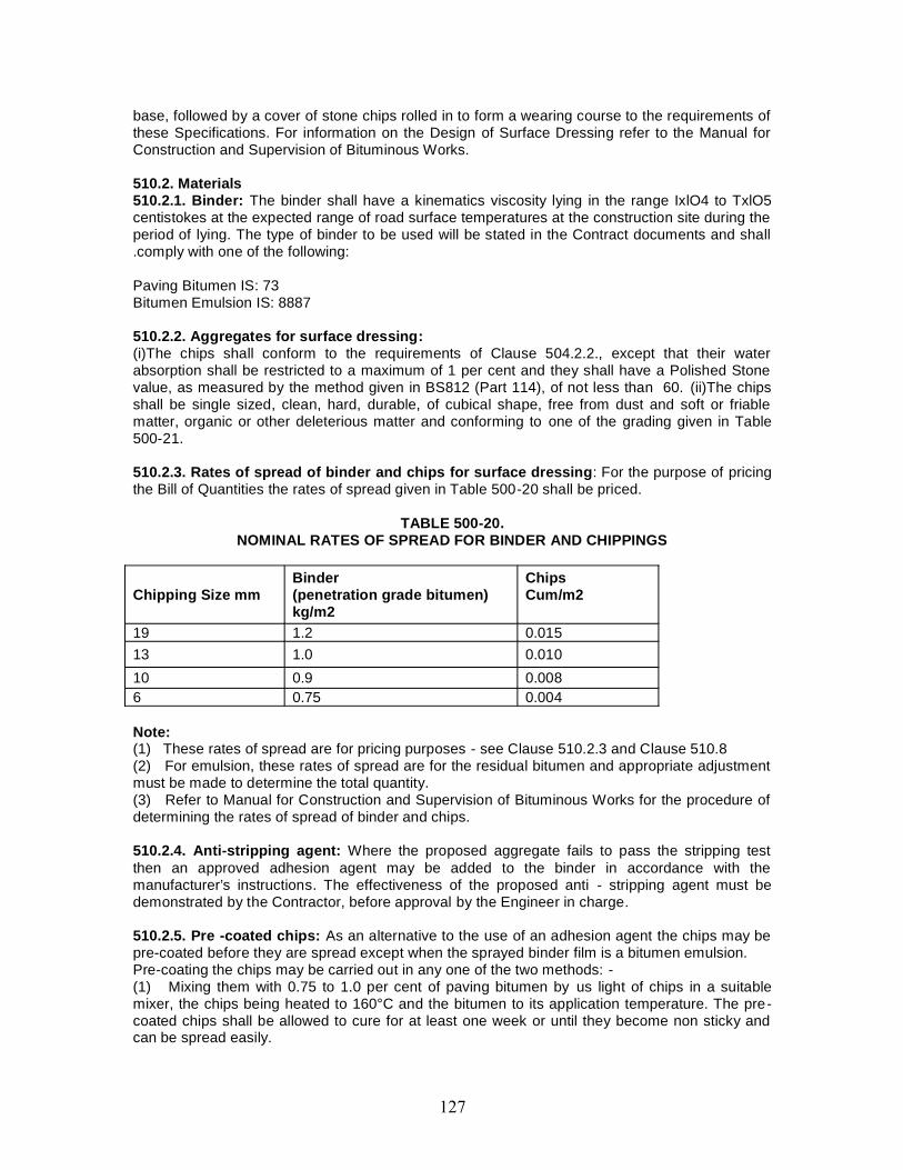
base, followed by a cover of stone chips rolled in to form a wearing course to the requirements ofthese Specifications. For information on the Design of Surface Dressing refer to the Manual forConstruction and Supervision of Bituminous Works.
510.2. Materials510.2.1. Binder: The binder shall have a kinematics viscosity lying in the range IxlO4 to TxlO5centistokes at the expected range of road surface temperatures at the construction site during theperiod of lying. The type of binder to be used will be stated in the Contract documents and shall.comply with one of the following:
Paving Bitumen IS: 73Bitumen Emulsion IS: 8887
510.2.2. Aggregates for surface dressing:(i)The chips shall conform to the requirements of Clause 504.2.2., except that their waterabsorption shall be restricted to a maximum of 1 per cent and they shall have a Polished Stonevalue, as measured by the method given in BS812 (Part 114), of not less than 60. (ii)The chipsshall be single sized, clean, hard, durable, of cubical shape, free from dust and soft or friablematter, organic or other deleterious matter and conforming to one of the grading given in Table500-21.
510.2.3. Rates of spread of binder and chips for surface dressing: For the purpose of pricingthe Bill of Quantities the rates of spread given in Table 500-20 shall be priced.
TABLE 500-20.NOMINAL RATES OF SPREAD FOR BINDER AND CHIPPINGS
Chipping Size mmBinder(penetration grade bitumen)kg/m2
ChipsCum/m2
19 1.2 0.01513 1.0 0.01010 0.9 0.0086 0.75 0.004
Note:(1) These rates of spread are for pricing purposes - see Clause 510.2.3 and Clause 510.8(2) For emulsion, these rates of spread are for the residual bitumen and appropriate adjustmentmust be made to determine the total quantity.(3) Refer to Manual for Construction and Supervision of Bituminous Works for the procedure ofdetermining the rates of spread of binder and chips.
510.2.4. Anti-stripping agent: Where the proposed aggregate fails to pass the stripping testthen an approved adhesion agent may be added to the binder in accordance with themanufacturer’s instructions. The effectiveness of the proposed anti - stripping agent must bedemonstrated by the Contractor, before approval by the Engineer in charge.
510.2.5. Pre -coated chips: As an alternative to the use of an adhesion agent the chips may bepre-coated before they are spread except when the sprayed binder film is a bitumen emulsion.Pre-coating the chips may be carried out in any one of the two methods: -(1) Mixing them with 0.75 to 1.0 per cent of paving bitumen by us light of chips in a suitablemixer, the chips being heated to 160°C and the bitumen to its application temperature. The pre-coated chips shall be allowed to cure for at least one week or until they become non sticky andcan be spread easily.
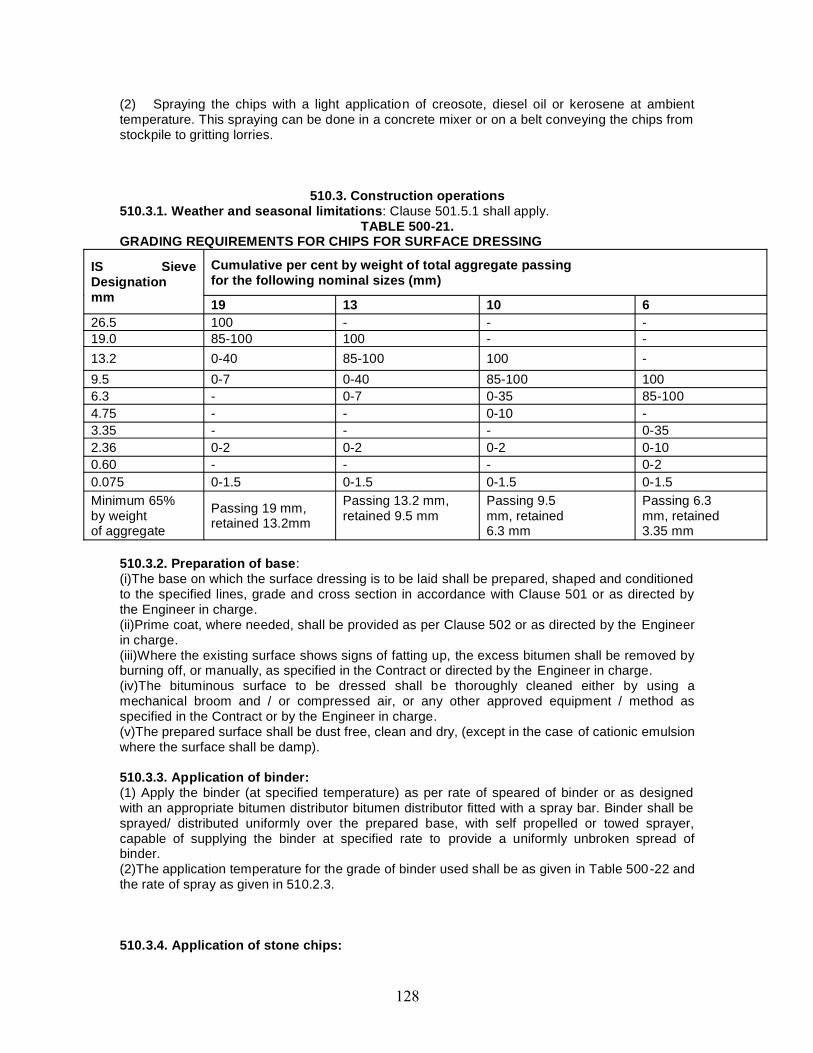
(2) Spraying the chips with a light application of creosote, diesel oil or kerosene at ambienttemperature. This spraying can be done in a concrete mixer or on a belt conveying the chips fromstockpile to gritting lorries.
510.3. Construction operations510.3.1. Weather and seasonal limitations: Clause 501.5.1 shall apply.
TABLE 500-21.GRADING REQUIREMENTS FOR CHIPS FOR SURFACE DRESSING
IS SieveDesignationmm
Cumulative per cent by weight of total aggregate passingfor the following nominal sizes (mm)
19 13 10 626.5 100 - - -19.0 85-100 100 - -13.2 0-40 85-100 100 -9.5 0-7 0-40 85-100 1006.3 - 0-7 0-35 85-1004.75 - - 0-10 -3.35 - - - 0-352.36 0-2 0-2 0-2 0-100.60 - - - 0-20.075 0-1.5 0-1.5 0-1.5 0-1.5Minimum 65%by weightof aggregate
Passing 19 mm,retained 13.2mm
Passing 13.2 mm,retained 9.5 mm
Passing 9.5mm, retained6.3 mm
Passing 6.3mm, retained3.35 mm
510.3.2. Preparation of base:(i)The base on which the surface dressing is to be laid shall be prepared, shaped and conditionedto the specified lines, grade and cross section in accordance with Clause 501 or as directed bythe Engineer in charge.(ii)Prime coat, where needed, shall be provided as per Clause 502 or as directed by the Engineerin charge.(iii)Where the existing surface shows signs of fatting up, the excess bitumen shall be removed byburning off, or manually, as specified in the Contract or directed by the Engineer in charge.(iv)The bituminous surface to be dressed shall be thoroughly cleaned either by using amechanical broom and / or compressed air, or any other approved equipment / method asspecified in the Contract or by the Engineer in charge.(v)The prepared surface shall be dust free, clean and dry, (except in the case of cationic emulsionwhere the surface shall be damp).
510.3.3. Application of binder:(1) Apply the binder (at specified temperature) as per rate of speared of binder or as designedwith an appropriate bitumen distributor bitumen distributor fitted with a spray bar. Binder shall besprayed/ distributed uniformly over the prepared base, with self propelled or towed sprayer,capable of supplying the binder at specified rate to provide a uniformly unbroken spread ofbinder.(2)The application temperature for the grade of binder used shall be as given in Table 500-22 andthe rate of spray as given in 510.2.3.
510.3.4. Application of stone chips:

The equipment and general procedure shall all be in accordance with the Manual for Constructionand Supervision of Bituminous Works. For relatively small areas of surface dressing, carefulapplication of chips by hand may be acceptable if approved by the Engineer. The rate ofapplication of chips shall be as determined by the procedure given in the Manual for Constructionand Supervision of Bituminous Works. Immediately after application of the binder, clean, drychips (in the case of emulsion binder the chippings may be damp) shall be spread uniformly onthe surface so as to cover the surface completely with a single layer of chips.It is desirable that clean, dry chippings be used, properly screened. Best results are obtainedwhen as little time as possible elapses between the application of a hot binder and chippings andin no case should this interval exceeds 15 minutes. The chippings should be uniformly distributedand precautions taken that the whole of the sprayed surface is covered uniformly without anyaccumulation of surplus material at any point. The chippings should be spread with a circularsweep of the shovel. Where different sizes of chips are to be used, spread the large size first andthen the fines this will give a smoother finish. If road is rutted the bigger chips may be used in theruts and smaller chips on the remainder. Hand brooming or light drag brooming should follow theapplication of the chippings prior to rolling. The excess of the chippings should be removed notless then 48 hours after applications and should not be swept back on the road. The chippingsshould not be dumped on the road, and should be cast parallel to the axis of the road and notacross it.
TABLE 500-22.SPRAYING TEMPERATURES FOR BINDERS
Binder grades Whirlingspray jets
Slot jets
Min°C Max°C Min°C Max°CPenetration Grades400/500 160 170 140 150280/320 165 175 150 160180/200 170 190 155 16580/100 180 200 165 175
510.3.5. Rolling:(i)Rolling of the chips should preferably be carried out by a pneumatic tyred roller in accordancewith Clause 501.6 and Clause 501.7.(ii)Traditional steel wheeled rollers tend to crush the aggregates and if their use cannot beavoided their weight should be limited to 8 tonnes.(iii)Rolling shall commence at the edges and progress towards the centre except in superelevated and uni-directional cambered portions where it shall proceed from the lower edge to thehigher edge.(iv)Each pass of the roller shall uniformly overlap not less than one-third of the track made in thepreceding pass.(v)While rolling is in progress additional chips shall be spread by hand in necessary quantitiesrequired to make up irregularities.(vi)Rolling shall continue until all aggregate particles are firmly embedded in the binder andpresent a uniform closed surface.
510.3.6. Application of second coat of surface dressing: Where surface dressing in two coatsis specified, the second coat should not be applied until the first coat has been open to traffic for 2or 3 weeks. The surface on which the second coat is laid must be clean and free of dust. Theconstruction operations for the second coat shall be the same as described in Clauses 510.3 .3 to510.3.5.
510.4. Opening to Traffic(i)Traffic shall not be permitted to run on any newly surface dressed area until the following day.
510.5. Surface Finish and Quality Control of Work
The surface finish of construction shall conform to the requirements of Clause 902.For control on the quality of materials supplied and the works carried out, the relevant
provisions of clause 501.8.4.1 shall apply.
510.6. Arrangements for TrafficDuring the period of construction, arrangements for traffic shall be made as directed by theEngineer in charge.
510.7. Measurement for PaymentEach coat of surface dressing shall be measured as finished work, for the area instructed to becovered, in square meters.
510.8. RateThe Contract unit rate for surface dressing, based on the notional rates of spread for binder andeach size of chippings given in Clause 510.2.3, which shall be adjusted, plus or minus, for thedifference between the notional rates; of spread and the rates of spread determined as describedin the Manual for Construction an d Supervision of Bituminous Works, and approved by theEngineer in charge, multiplied by the rates entered in the Bill of Quantities for binder and eachsize of chipping. The adjusted rate shall be payment in full for carrying out the required operationsincluding full compensation for all components listed in Clause 501.8.8.2.(i) to (xi).
511. OPEN-GRADED PREMIX SURFACING511.1. Open-graded Premix Surfacing using Penetration Bitumen or Cutback.
511.1.1. General: This work shall consist of the preparation, laying and compaction of an open-graded premix surfacing material of 20 mm thickness composed of small-sized aggregatepremixed with a bituminous binder on a previously prepared base, in accordance with therequirements of these Specifications, to serve as a wearing course.
511.1.2. Materials511.1.2.1. Binder: The binder shall be penetration bitumen of a suitable grade as specified in theContract or as directed by the Engineer in charge, and satisfying the requirements of IS: 73.
511.1.2.2. Aggregate: The aggregate shall conform to Clause 504.2.2 except that the waterabsorption shall be limited to a maximum of 1 per cent. The Polished Stone Value, as measuredby the test in BS 812- (Part 114), shall not be less than 55.
511.1.2.3. Proportioning of materials: The materials shall be proportioned in accordance withTable 500-23.
511.13. Construction operations
511.1.3.1. Weather and seasonal limitations: Clause 501.5.1 shall apply.
511.1.3.2. Preparation of surface:(i)The underlying surface on which the bituminous surfacing is to be laid shall be prepared,shaped and conditioned to the specified lines, grade and cross-section in accordance with Clause501.(ii)A prime coat where needed shall be applied in accordance with Clause 502 as directed by theEngineer in charge.
TABLE 500-23.QUANTITIES OF MATERIALS REQUIRED FOR 10 m’ OF ROAD SURFACE FOR 20mmTHICK OPEN-GRADED PREMIX SURFACING USING PENETRATION BITUMEN ORCUTBACK
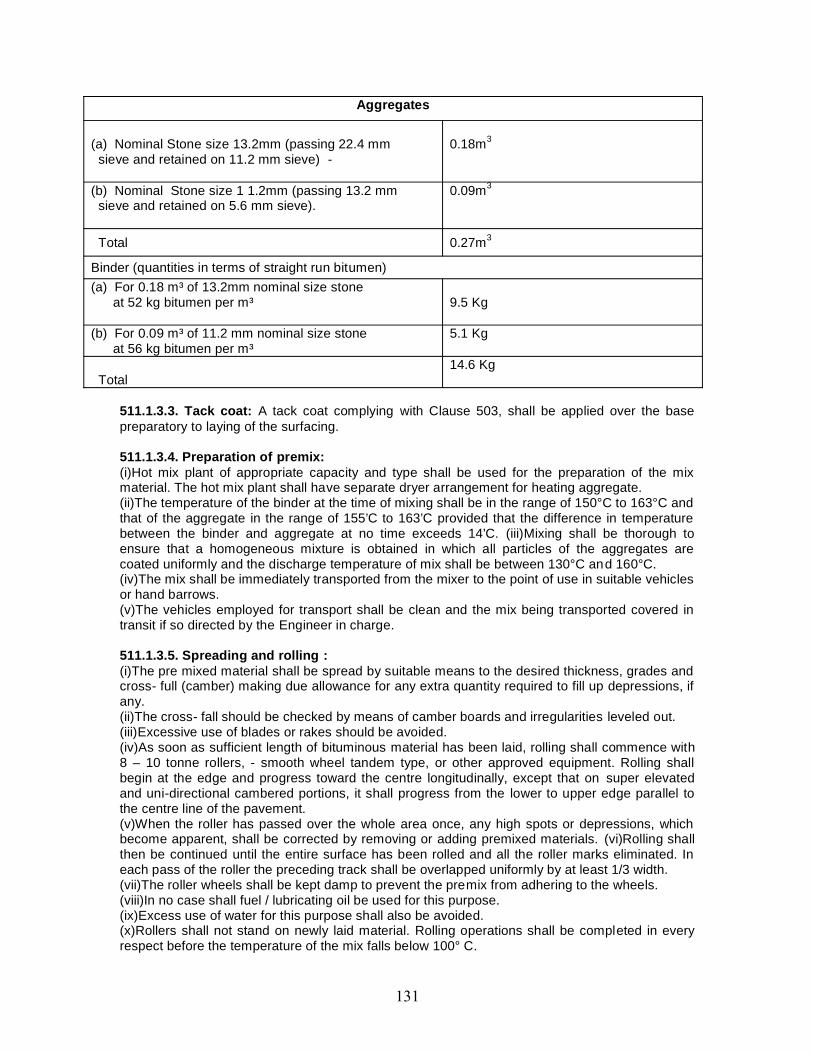
Aggregates
(a) Nominal Stone size 13.2mm (passing 22.4 mmsieve and retained on 11.2 mm sieve) -
0.18m3
(b) Nominal Stone size 1 1.2mm (passing 13.2 mmsieve and retained on 5.6 mm sieve).
0.09m3
Total 0.27m3
Binder (quantities in terms of straight run bitumen)(a) For 0.18 m³ of 13.2mm nominal size stone
at 52 kg bitumen per m³ 9.5 Kg
(b) For 0.09 m³ of 11.2 mm nominal size stoneat 56 kg bitumen per m³
5.1 Kg
Total14.6 Kg
511.1.3.3. Tack coat: A tack coat complying with Clause 503, shall be applied over the basepreparatory to laying of the surfacing.
511.1.3.4. Preparation of premix:(i)Hot mix plant of appropriate capacity and type shall be used for the preparation of the mixmaterial. The hot mix plant shall have separate dryer arrangement for heating aggregate.(ii)The temperature of the binder at the time of mixing shall be in the range of 150°C to 163°C andthat of the aggregate in the range of 155’C to 163’C provided that the difference in temperaturebetween the binder and aggregate at no time exceeds 14’C. (iii)Mixing shall be thorough toensure that a homogeneous mixture is obtained in which all particles of the aggregates arecoated uniformly and the discharge temperature of mix shall be between 130°C and 160°C.(iv)The mix shall be immediately transported from the mixer to the point of use in suitable vehiclesor hand barrows.(v)The vehicles employed for transport shall be clean and the mix being transported covered intransit if so directed by the Engineer in charge.
511.1.3.5. Spreading and rolling :(i)The pre mixed material shall be spread by suitable means to the desired thickness, grades andcross- full (camber) making due allowance for any extra quantity required to fill up depressions, ifany.(ii)The cross- fall should be checked by means of camber boards and irregularities leveled out.(iii)Excessive use of blades or rakes should be avoided.(iv)As soon as sufficient length of bituminous material has been laid, rolling shall commence with8 – 10 tonne rollers, - smooth wheel tandem type, or other approved equipment. Rolling shallbegin at the edge and progress toward the centre longitudinally, except that on super elevatedand uni-directional cambered portions, it shall progress from the lower to upper edge parallel tothe centre line of the pavement.(v)When the roller has passed over the whole area once, any high spots or depressions, whichbecome apparent, shall be corrected by removing or adding premixed materials. (vi)Rolling shallthen be continued until the entire surface has been rolled and all the roller marks eliminated. Ineach pass of the roller the preceding track shall be overlapped uniformly by at least 1/3 width.(vii)The roller wheels shall be kept damp to prevent the premix from adhering to the wheels.(viii)In no case shall fuel / lubricating oil be used for this purpose.(ix)Excess use of water for this purpose shall also be avoided.(x)Rollers shall not stand on newly laid material. Rolling operations shall be completed in everyrespect before the temperature of the mix falls below 100° C.

(xi)Joints along and transverse to the surfacing laid and compacted earlier shall be cut verticallyto "heir full depth so as to expose fresh surface which shall be painted with an L in coat ofappropriate binder before the new mix is placed against it.
511.1.3.6. Seal coat: A seal coat of the type specified in the Contract shall be applied to thesurface immediately after laying the surfacing.
511.1.4. Opening to traffic: No traffic shall be allowed on the road until the seal coat has beenlaid. After the seal coat is laid, the road may be opened to traffic as given below.
In the case of Type B seal coat, traffic may be allowed soon after final rolling when thepremixed material has cooled down to the surrounding temperature. In the case of Type A sealcoat, traffic shall not be permitted to run on any newly sealed area until the following day. Inspecial circumstances, however, the Engineer in charge may open the road to traff ic immediatelyafter rolling, but in such cases traffic speed shall be rigorously limited to 16 km per hour until thefollowing day.
511.1.5. Surface finish and quality control of work: The surface finish of construction shallconform to the requirements of Clause 902. For control of the quality of materials supplied andthe works carried out, the relevant provisions of 501.8.4.1 apply.
511.1.6. Arrangements for traffic: During the period of construction, arrangement of traffic shallbe made in as per direction of Engineer in charge.
511.1.7. Measurement for payment:(1)Open graded premix surfacing shall be measured as finished work, for the area instructed tobe covered, in square meters.(2)The area will be the net area covered, and all allowance for wastage and cutting of joints shallbe deemed to be included in the rate.
511.1.8. Rate: The contract unit rate for open -graded premix surfacing shall be payment in fullfor carrying out the required operations including full compensation for all components listed inClause 501.8.8.2. (i) to (xi).
511.2. Open graded premix surfacing using cationic bitumen emulsion511.2.1. General:This work shall consist of the preparation, laying and compaction of an open graded premixsurfacing of 20 mm thickness composed of small-sized aggregate premixed with a cationicbitumen emulsion on a previously prepared surface, in accordance with the requirements of theseSpecifications, to serve as a wearing course.
511.2.2. Materials511.2.2.1. Binder:(1)The binder for Premix wearing course shall be cationic bitumen emulsion of Medium Setting(MS) grade complying with I.S.8887 and having a bitumen content 65 per cent minimum byweight.(2)For liquid seal coat RS grade of Cationic bitumen emulsion shall be used. Where expresslyspecified in the Contract MS grade emulsion shall be used or otherwise directed by the Engineerin charge.(3)Slow Setting (SS) grade Cationic bitumen Emulsion shall be used for premix seal coat.
511.2.2.2. Aggregate: The requirements of Clause 511.1.2.2. Shall apply.
511.2.3. Proportioning of materials: The materials shall be proportioned as quantities given inTables 500-24 and 500-25.
TABLE 500-24.QUANTITIES OF AGGREGATE FOR 10 M1 AREA
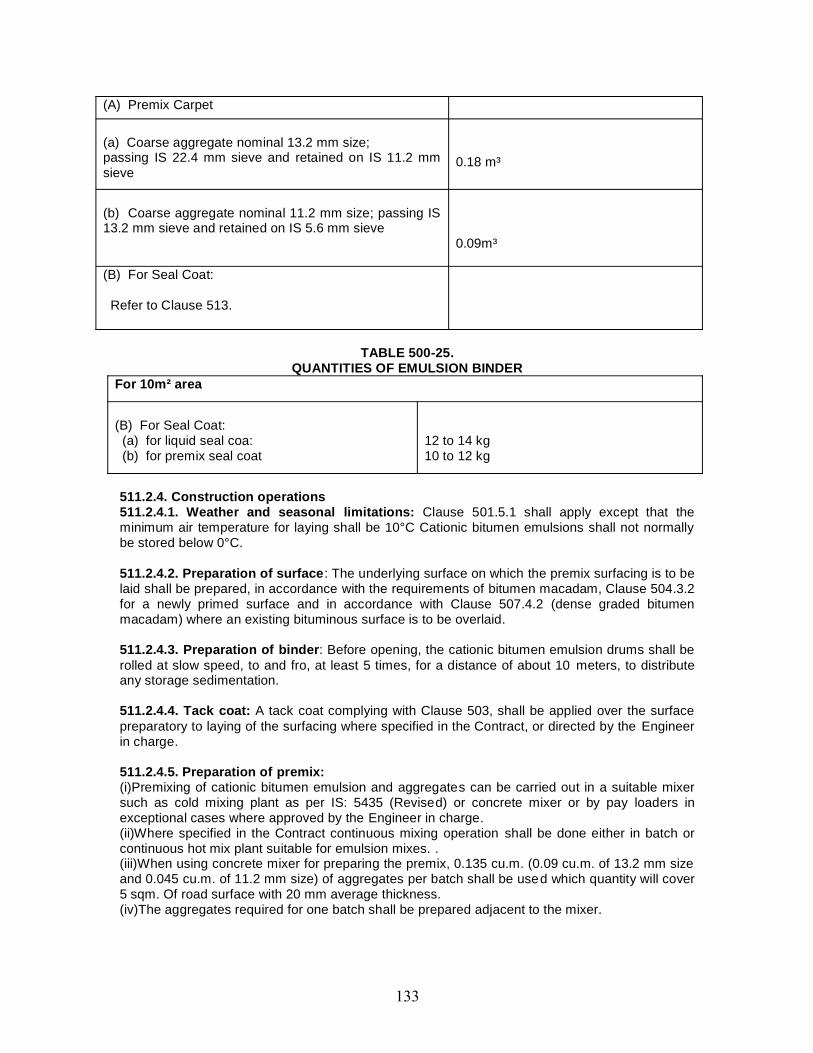
(A) Premix Carpet
(a) Coarse aggregate nominal 13.2 mm size;passing IS 22.4 mm sieve and retained on IS 11.2 mmsieve
0.18 m³
(b) Coarse aggregate nominal 11.2 mm size; passing IS13.2 mm sieve and retained on IS 5.6 mm sieve
0.09m³
(B) For Seal Coat:
Refer to Clause 513.
TABLE 500-25.QUANTITIES OF EMULSION BINDER
For 10m² area
(B) For Seal Coat:(a) for liquid seal coa:(b) for premix seal coat
12 to 14 kg10 to 12 kg
511.2.4. Construction operations511.2.4.1. Weather and seasonal limitations: Clause 501.5.1 shall apply except that theminimum air temperature for laying shall be 10°C Cationic bitumen emulsions shall not normallybe stored below 0°C.
511.2.4.2. Preparation of surface: The underlying surface on which the premix surfacing is to belaid shall be prepared, in accordance with the requirements of bitumen macadam, Clause 504.3.2for a newly primed surface and in accordance with Clause 507.4.2 (dense graded bitumenmacadam) where an existing bituminous surface is to be overlaid.
511.2.4.3. Preparation of binder: Before opening, the cationic bitumen emulsion drums shall berolled at slow speed, to and fro, at least 5 times, for a distance of about 10 meters, to distributeany storage sedimentation.
511.2.4.4. Tack coat: A tack coat complying with Clause 503, shall be applied over the surfacepreparatory to laying of the surfacing where specified in the Contract, or directed by the Engineerin charge.
511.2.4.5. Preparation of premix:(i)Premixing of cationic bitumen emulsion and aggregates can be carried out in a suitable mixersuch as cold mixing plant as per IS: 5435 (Revised) or concrete mixer or by pay loaders inexceptional cases where approved by the Engineer in charge.(ii)Where specified in the Contract continuous mixing operation shall be done either in batch orcontinuous hot mix plant suitable for emulsion mixes. .(iii)When using concrete mixer for preparing the premix, 0.135 cu.m. (0.09 cu.m. of 13.2 mm sizeand 0.045 cu.m. of 11.2 mm size) of aggregates per batch shall be used which quantity will cover5 sqm. Of road surface with 20 mm average thickness.(iv)The aggregates required for one batch shall be prepared adjacent to the mixer.
(v)First the coarse aggregate of 13.2 mm size shall be placed into the mixer followed by 5 to 6.5kg of Cationic bitumen emulsion and then the (this line is corrupted in the text is also) bitumenemulsion.(vi)After the materials have been mixed thoroughly, the mix shall be immediately transported tothe laying site in suitable vehicles.(vii)Too much mixing shall be avoided.(viii)When mixed manually by shovels, with the approval of the Engineer in charge.0.06 cu.m. Ofaggregates can be conveniently mixed in one heap, with appropriate quantity of emulsion. It ispreferable to make the aggregates damp before mixing as it reduces the effort required for mixingand also helps to get better coating of aggregates.(ix)The 13.2 mm size aggregates and emulsion are mixed first and then the 11.2 mm sizeaggregates and remaining quantity of emulsion are added and mixed.(x)Too much mixing shall be avoided.
511.2.4.6. Spreading and rolling:(i)The premixed cationic bitumen emulsion and aggregates shall be spread within 10 minutes ofapplying the tack coat.(ii)All leveling, raking, etc. should be completed within 20 minutes of the time of mixing.(iii)The mix should be spread uniformly to the desired thickness, grades and crossfall (camber)making due allowance for any extra quantity required to fill up depressions, if any.(iv)The crossfall should be checked by means of camber boards and irregularities leveled out.Too much raking is to be avoided.(v)The rolling shall start immediately after laying the premix.(vi)A smooth wheeled tandem roller of 8-10 tonnes shall be used, unless other compactionmethods are approved by the Engineer in charge, based on the results of laying trials, ifnecessary.(vii)While rolling, wheels of roller should be clean and kept moist to prevent the premix fromadhering to the wheels.(viii)In no case shall fuel / lubricating oil be used for this purpose.(ix)Use of water for this purpose shall be strictly limited to an absolute minimum.(x)Rolling shall commence at the edges and progress towards the centre longitudinally except inthe case of super elevated and uni-directional cambered sections where rolling shall be carriedout from the lower edge towards the higher edge parallel to the centre line of the road.(xi)After one pass of roller over the whole area, depressions or uncovered spots should becorrected by adding premix material.(xii)Rolling shall be continued until the entire surface has been rolled to maximum compactionand all the roller marks eliminated.(xiii)In each pass of the roller the preceding track shall be overlapped uniformly by at least 1/3width.(xiv)Roller(s) shall not stand on newly laid material.(xv)Joints both longitudinal and transverse to the road sections laid and compacted earlier, shallbe cut vertically to their full depth so as to expose fresh surface which shall be painted with a thinsurface coat of binder before the new mix is placed against it.
511.2.4.7. Seal coat: A seal coat, conforming to Clause 510 or Clause 513, as specified in theContract, shall be applied 4 to 6 hours after laying the premix carpet.
511.2.5. Opening to traffic:(i)Traffic should not be allowed over the premix surface with or without seal coat, for 6 to 8 hoursafter rolling.(ii)In case of single lane roads, traffic shall be allowed onto the surface once it has reachedambient temperature, but speed must be rigorously restricted to not more than 16 km per hour.(iii)If any premix material is picked up by vehicle tyres, the spot shall be filled up by new mix.(iv)If traffic conditions permit, the road shall not be opened until a full 24 hours after laying.
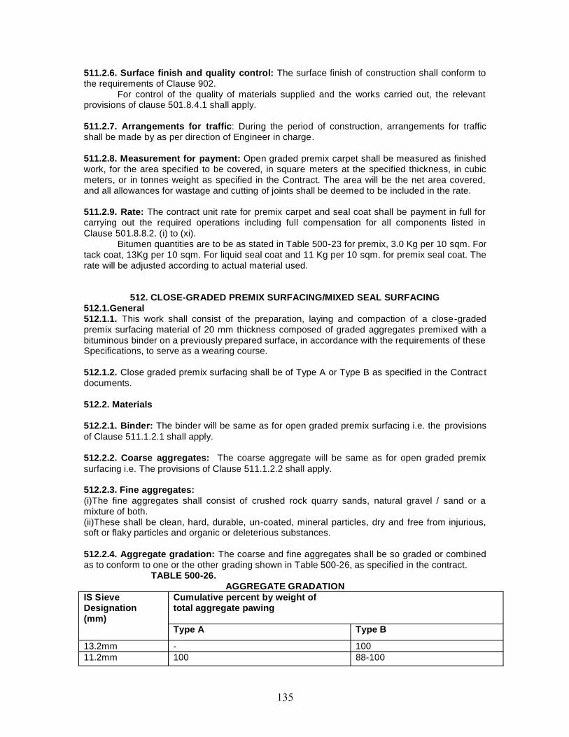
511.2.6. Surface finish and quality control: The surface finish of construction shall conform tothe requirements of Clause 902.
For control of the quality of materials supplied and the works carried out, the relevantprovisions of clause 501.8.4.1 shall apply.
511.2.7. Arrangements for traffic: During the period of construction, arrangements for trafficshall be made by as per direction of Engineer in charge.
511.2.8. Measurement for payment: Open graded premix carpet shall be measured as finishedwork, for the area specified to be covered, in square meters at the specified thickness, in cubicmeters, or in tonnes weight as specified in the Contract. The area will be the net area covered,and all allowances for wastage and cutting of joints shall be deemed to be included in the rate.
511.2.9. Rate: The contract unit rate for premix carpet and seal coat shall be payment in full forcarrying out the required operations including full compensation for all components listed inClause 501.8.8.2. (i) to (xi).
Bitumen quantities are to be as stated in Table 500-23 for premix, 3.0 Kg per 10 sqm. Fortack coat, 13Kg per 10 sqm. For liquid seal coat and 11 Kg per 10 sqm. for premix seal coat. Therate will be adjusted according to actual material used.
512. CLOSE-GRADED PREMIX SURFACING/MIXED SEAL SURFACING512.1.General512.1.1. This work shall consist of the preparation, laying and compaction of a close-gradedpremix surfacing material of 20 mm thickness composed of graded aggregates premixed with abituminous binder on a previously prepared surface, in accordance with the requirements of theseSpecifications, to serve as a wearing course.
512.1.2. Close graded premix surfacing shall be of Type A or Type B as specified in the Contractdocuments.
512.2. Materials
512.2.1. Binder: The binder will be same as for open graded premix surfacing i.e. the provisionsof Clause 511.1.2.1 shall apply.
512.2.2. Coarse aggregates: The coarse aggregate will be same as for open graded premixsurfacing i.e. The provisions of Clause 511.1.2.2 shall apply.
512.2.3. Fine aggregates:(i)The fine aggregates shall consist of crushed rock quarry sands, natural gravel / sand or amixture of both.(ii)These shall be clean, hard, durable, un-coated, mineral particles, dry and free from injurious,soft or flaky particles and organic or deleterious substances.
512.2.4. Aggregate gradation: The coarse and fine aggregates shall be so graded or combinedas to conform to one or the other grading shown in Table 500-26, as specified in the contract.
TABLE 500-26.AGGREGATE GRADATION
IS SieveDesignation(mm)
Cumulative percent by weight oftotal aggregate pawing
Type A Type B
13.2mm - 10011.2mm 100 88-100
5.6mm 52-8814-38
31 -522.8mm 5-250.090mm 0-5 0-5
512.2.5. Proportioning of materials: The total quantity of aggregates used for Type A or Bclose-graded premix surfacing shall be 0.27 cubic meters per 10 square meter area. The quantityof binder used for premixing in terms of straight-run bitumen shall be 22.0 kg and 19.0 kg per 10square meter area for Type A and Type B surfacing respectively.
512.3. Construction Operations:- The construction operation will be same as for open gradedpremix surfacing i.e. The provisions of Clause 511.1.3.1 through 511.1.3.5 shall apply.
512.4. Opening to TrafficTraffic may be allowed after completion of the final rolling when the mix has cooled down to thesurrounding temperature. Excessive traffic speeds should not be permitted.
512.5. Surface Finish and Quality Control of WorkThe surface finish of construction shall conform to the requirements of Clause 902. For control onthe quality of materials supplied and the works carried out, the relevant provisions of clause of501.8.4.1.
512.6. Arrangements for TrafficDuring the period of construction, arrangements for traffic shall be as per direction Engineer incharge.
512.7. Measurements for Payment(i)Close-graded premix surfacing, Type A or B shall be measured as finished work, for the areaspecified to be covered, in square meters at a specified thickness.(ii) The area will be the net area covered, and all allowances for wastage and cutting of jointsshall be deemed to be included in the rate.
512.8. RateThe contract unit rate for close-graded premix surfacing, Type A or B shall be payment in full forcarrying out the required operations including full compensation for all components listed inClause 501.8.8.2. (i) to (xi).
513. SEAL COAT513.1. General513.1.1. This work shall consist of the application of a seal coat for sealing the voids in abituminous surface laid to the specified levels, grade and cross fall (camber).
513.1.2. Seal coat shall be of either of the two types specified below:(A) Liquid seal coat comprising of an application of a layer of bituminous binder followed by acover of stone chips.(B) Premixed seal coat comprising of a thin application of tine aggregate premixed \MI|Ibituminous binder.
513.2. Materials513.2.1. Binder: the binder will be same as for open graded premix surfacing i.e. therequirements of Clauses 511.1.2.1 and 511.2.2.1 shall apply.The quantity of bitumen per 10 square meters shall be 9.8 kg for Type A, and 6.8 kg for Type Bseal coal. Where bituminous emulsion is used as a binder the quantities for Type A and Type Bseal coats shall be 15 Kg and 10.5 Kg respectively.
513.2.2. Stone chips for Type A seal coat:
(i)The stone chips shall consist of angular fragments of clean, hard, tough and durable rock ofuniform quality throughout.(ii)They should be free of soft or disintegrated stone, organic or other deleterious matter. Stonechips shall be of 6.7mm size defined as 100 per cent passing through 11.2 mm sieve andretained on 2.36 mm sieve.(iii)The quantity used for spreading shall be 0.09 cubic meter per 10 square meter area. (iv)Thechips shall satisfy the quality requirements in Table 500-3 except that the upper limit for waterabsorption value shall be 1 per cent.
513.2.3. Aggregate for Type B seal coat:(i)The aggregate shall be sand or grit and shall consist of clean, hard, durable, uncoated dryparticles and shall be free from dust, soft or flaky / elongated material, organic matter or otherdeleterious substances.(ii)The aggregate shall pass 2.36mm sieve and be retained on 180 micron sieve.(iii)The quantity used for premixing shall be 0.06 cubic meters per 10 square meters area.
513.3. Construction Operations513.3.1. Weather and seasonal limitations: The requirements of Clause 501.5.1 shall apply.
513.3.2. Preparation of surface:(i)The seal coat shall be applied immediately after laying the bituminous course which is requiredto be sealed.(ii)Before application of seal coat materials, the surface shall be cleaned free of any dust or otherextraneous matter.
513.3.3. Construction of Type A seal coat:(i)Bitumen shall be heated to 150°C-163°C and sprayed at the rate specified on the dry surface ina uniform manner with a self-propelled mechanical sprayer as described in the Manual forConstruction and Supervision of Bituminous Works.(ii)Immediately after the application of binder, stone chips, which shall be clean and dry, shall bespread uniformly at the rate specified on the surface preferably by means of a self -propelled ortowed mechanical grit spreader so as to cover the surface completely.(iii)If necessary, the surface shall be brushed 10 ensure uniform spread of chips.(iv)Immediately after the application of the cover material, the entire surface shall be rolled with a8 - 10 tonne smooth wheeled steel roller, 8 - 10 tonnes static weight vibratory roller, or otherequipment approved by the Engineer in charge after laying trials if required.(v)Rolling shall commence at the edges and progress towards the centre except in superelevated and unidirectional cambered portions where it shall proceed from the lower edge to thehigher edge.(vi)Each pass of the roller shall uniformly overlap not less than one-third of the track made in thepreceding pass.(vii)While rolling is in progress, additional chips shall be spread by h and in necessary quantitiesrequired to make up irregularities.(viii)Rolling shall continue until all aggregate panicles are firmly embedded in the binder andpresent a uniform closed surface.
513.3.4. Construction of Type B seal coat:(i)A mixer of appropriate capacity and type approved by the Engineer in charge shall be used forpreparation of the mixed material.(ii)The plant shall have separate dryer arrangements for heating aggregate.(iii)The binder shall be heated in boilers of suitable design, approved by the Engineer in charge tothe temperature appropriate to the grade of bitumen or as directed by the Engineer in charge.(iv)The aggregates shall be dry and suitably heated to a temperature between 150°Cand 165°Cor as directed by the Engineer in charge before these components are placed in the mixer.(v)Mixing of binder with aggregates to the specified proportions shall be continued until the latterare thoroughly coated with the former.
(vi)The mix shall be immediately transported from the mixing plant to the point of use and spreaduniformly on the bituminous surface to be sealed.(vii)As soon as a sufficient length has been covered with the premixed material, the surface shallbe rolled with an 8-10 tonne smooth-wheeled roller.(viii)Rolling shall be continued until the premixed material completely seals the voids in thebituminous course and a smooth uniform surface is obtained.
513.4. Opening to Traffic(i)In the case of Type B seal coat, traffic may be allowed soon after final rolling when thepremixed material has cooled down to the surrounding temperature.(ii)In the case of Type A seal coat, traffic shall not be permitted to run on any newly sealed ar eauntil the following day.(iii)In special circumstances, however, the Engineer in charge may open the road to trafficimmediately after rolling, but in such cases traffic speed shall be rigorously limited to 16 km perhour until the following day.
513.5. Surface Finish and Quality Control of Work(i)The surface finish of construction shall conform to the requirements of Clause 902.(ii)For control on the quality of materials supplied and the works carried out, the relevantprovisions of clause of 501.8.4.1.
513.6. Arrangements for TrafficDuring the period of construction, arrangements for traffic shall be made by as per direction ofEngineer in charge.
513.7. Measurement for PaymentSeal coat, Type A or B shall be measured as finished work, over the area specified to be covered,in square meters at the thickness specified in the Contract.
513.8. RateThe contract unit rate for seal coat Type A or B shall be payment in full for carrying out therequired operations including full compensation for all components listed in Clause 501.8.8.2. (i)to (xi).
514. SUPPLY OF STONE AGGREGATESFOR PAVEMENT COURSES514.1. General(i)This Specification Clause shall apply to the supply of stone aggregates only.(ii)The work shall consist only of collection, transportation and stacking the stone aggregates andstone filler for subsequent use in pavement courses.(iii)The actual work of laying the pavement courses shall, however, be governed by the individualSpecification Clause for the actual work, given elsewhere in this Specification. (iv)The size andquantities of the aggregates to be supplied shall be so selected by the Engineer in charge that thegrading requirements set forth in the individual Specification Clauses for the pavement courses,for which the supply is intended, are satisfied.(v)All the materials shall be procured from approved sources and shall conform to the physicalrequirements, specified in the respective Specification Clauses for the individual items givenelsewhere in this Specification.
514.2. Sizes of Stone AggregatesThe stone aggregates shall be designated by their standard sizes in the Contract and shallconform to the requirements shown in Table 500-27.
TABLE 500-27.SIZE REQUIREMENTS FOR COARSE STONE AGGREGATES
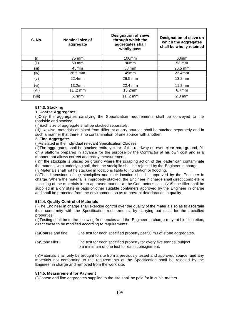
S. No. Nominal size ofaggregate
Designation of sievethrough which theaggregates shall
wholly pass
Designation of sieve onwhich the aggregates
shall be wholly retained
(i) 75 mm 106mm 63mm(ii) 63 mm 90mm 53 mm(iii) 45mm 53 mm 26.5 mm(iv) 26.5 mm 45mm 22.4mm(v) 22.4mm 26.5 mm 13.2mm
(vi) 13.2mm 22.4 mm 11.2mm(vii) 11 .2 mm 13.2mm 6.7mm(viii) 6.7mm 11 .2 mm 2.8 mm
514.3. Stacking1. Coarse Aggregates:(i)Only the aggregates satisfying the Specification requirements shall be conveyed to theroadside and stacked.(ii)Each size of aggregate shall be stacked separately.(iii)Likewise, materials obtained from different quarry sources shall be stacked separately and insuch a manner that there is no contamination of one source with another.2. Fine Aggregate:(i)As stated in the individual relevant Specification Clauses.(ii)The aggregates shall be stacked entirely clear of the roadway on even clear hard ground, 01on a platform prepared in advance for the purpose by the Contractor at his own cost and in amanner that allows correct and ready measurement.(iii)If the stockpile is placed on ground where the scraping action of the loader can contaminatethe material with underlying soil, then the stockpile shall be rejected by the Engineer in charge.(iv)Materials shall not he stacked in locations liable to inundation or flooding.(v)The dimensions of the stockpiles and their location shall be approved by the Engineer incharge. Where the material is improperly stacked, the Engineer in charge shall direct complete re-stacking of the materials in an approved manner at the Contractor’s cost. (vi)Stone filler shall besupplied in a dry state in bags or other suitable containers approved by the Engineer in chargeand shall be protected from the environment, so as to prevent deterioration in quality.
514.4. Quality Control of Materials(i)The Engineer in charge shall exercise control over the quality of the materials so as to ascertaintheir conformity with the Specification requirements, by carrying out tests for the specifiedproperties.(ii)Testing shall be to the following frequencies and the Engineer in charge may, at his discretion,direct these to be modified according to requirements:
(a)Coarse and fine: One test for each specified property per 50 m3 of stone aggregates.
(b)Stone filler: One test for each specified property for every five tonnes, subjectto a minimum of one test for each consignment.
(iii)Materials shall only be brought to site from a previously tested and approved source, and anymaterials not conforming to the requirements of the Specification shall be rejected by theEngineer in charge and removed from the work site.
514.5. Measurement for Payment(i)Coarse and fine aggregates supplied to the site shall be paid for in cubic meters.

(ii)The actual volume of the aggregates to be paid for shall be computed after deducting thespecified percentages in Table 500-28, from the volume computed by stack measurements, toallow for bulking.(iii)Unless otherwise directed by the Engineer in charge, measurements shall not be taken untilsufficient materials for use on the road have been collected and stacked. (iv)Immediately aftermeasurement, the stacks shall be marked by white wash or other means as directed by theEngineer in charge. Stone filler as delivered to the site shall be measured in tonnes.
TAKLE 500-28.PER CENT REDUCTION IN VOLUME OF AGGREGATES
S. No. Standard sizeof aggregates
Percentage reduction in volumecomputed by stack measurements to
arrive at the volume to be paid for1. 75 mm and 63 mm 12.52. 45 mm and 26.5 mm 10.03. 22.4 mm, 13.2 mm, 11.2 mm and 6.7 mm 5.04. Fine aggregate 5.0
514.6. RatesThe contract unit rates for different sizes of coarse aggregate, fine aggregate and stone filler shallbe payment in full for collecting, conveying and stacking or storing at the site including fullcompensation for:(i) All royalties, fees, rents where necessary;(ii) All leads and lifts; and(iii)All labour, tools, equipment and incidentals to complete the work to the Specifications.(iv) All necessary testing of material, both initial, to approve the source, and regular control testingthereafter.
515. MASTIC ASPHALT515.1. General(i)This work shall consist of constructing a single layer of mastic asphalt wearing course for roadpavements and bridge decks.(ii)Mastic asphalt is an intimate homogeneous mixture of selected well graded aggregates, fillerand bitumen in such proportions as to yield a plastic and void less mass, which when applied hotcan be toweled and floated to form a very dense impermeable surfacing.
515.2. Materials515.2.1. Binder:(i)Subject to the approval of the Engineer in charge, the binder shall be a paving grade bitumenmeeting the requirements given in Table 500-29.
515.2.2. Coarse aggregate:(i)The coarse aggregate shall consist of crushed stone, crushed gravel/shingle or other stones.(ii)They shall be clean, hard, durable, of fairly cubical shape, uncoated and free from soft, organicor other deleterious substances. They shall satisfy the physical.
TABLE 500-29.REQUIREMENTS FOR PHYSICAL PROPERTIES OF BINDER
Property Unit Test method RequirementPenetration at 25°C IS 1203 15 ±5*Softening point. °C IS 1205 65 ± 10Loss on heating for 5hat 163°C, % by mass Max IS 1212 2.0
Solubility intrichloroethylene, %by mass
Min IS 1216 95
Ash (mineral matter),% by mass Max IS 1217 1.0
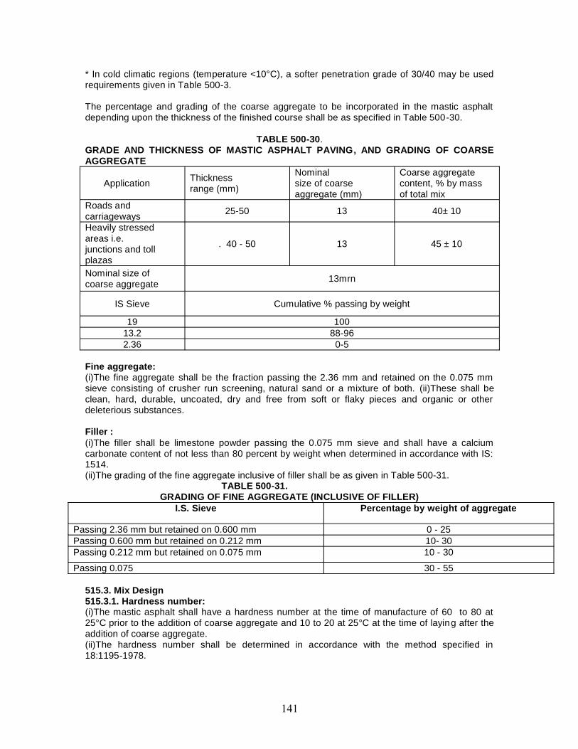
* In cold climatic regions (temperature <10°C), a softer penetration grade of 30/40 may be usedrequirements given in Table 500-3.
The percentage and grading of the coarse aggregate to be incorporated in the mastic asphaltdepending upon the thickness of the finished course shall be as specified in Table 500-30.
TABLE 500-30.GRADE AND THICKNESS OF MASTIC ASPHALT PAVING, AND GRADING OF COARSEAGGREGATE
Application Thicknessrange (mm)
Nominalsize of coarseaggregate (mm)
Coarse aggregatecontent, % by massof total mix
Roads andcarriageways 25-50 13 40± 10
Heavily stressedareas i.e.junctions and tollplazas
. 40 - 50 13 45 ± 10
Nominal size ofcoarse aggregate 13mrn
IS Sieve Cumulative % passing by weight
19 10013.2 88-962.36 0-5
Fine aggregate:(i)The fine aggregate shall be the fraction passing the 2.36 mm and retained on the 0.075 mmsieve consisting of crusher run screening, natural sand or a mixture of both. (ii)These shall beclean, hard, durable, uncoated, dry and free from soft or flaky pieces and organic or otherdeleterious substances.
Filler :(i)The filler shall be limestone powder passing the 0.075 mm sieve and shall have a calciumcarbonate content of not less than 80 percent by weight when determined in accordance with IS:1514.(ii)The grading of the fine aggregate inclusive of filler shall be as given in Table 500-31.
TABLE 500-31.GRADING OF FINE AGGREGATE (INCLUSIVE OF FILLER)
I.S. Sieve Percentage by weight of aggregate
Passing 2.36 mm but retained on 0.600 mm 0 - 25Passing 0.600 mm but retained on 0.212 mm 10- 30Passing 0.212 mm but retained on 0.075 mm 10 - 30
Passing 0.075 30 - 55
515.3. Mix Design515.3.1. Hardness number:(i)The mastic asphalt shall have a hardness number at the time of manufacture of 60 to 80 at25°C prior to the addition of coarse aggregate and 10 to 20 at 25°C at the time of laying after theaddition of coarse aggregate.(ii)The hardness number shall be determined in accordance with the method specified in18:1195-1978.
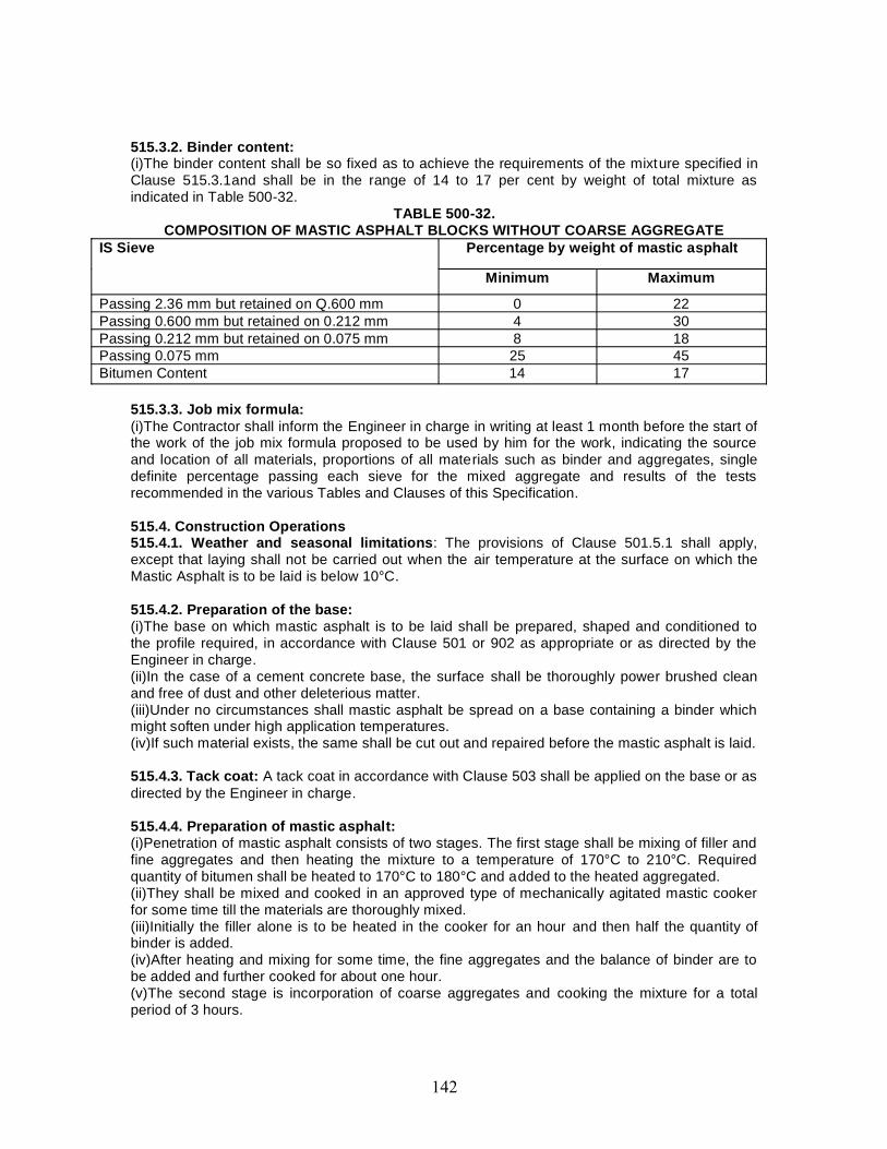
515.3.2. Binder content:(i)The binder content shall be so fixed as to achieve the requirements of the mixture specified inClause 515.3.1and shall be in the range of 14 to 17 per cent by weight of total mixture asindicated in Table 500-32.
TABLE 500-32.COMPOSITION OF MASTIC ASPHALT BLOCKS WITHOUT COARSE AGGREGATE
IS Sieve Percentage by weight of mastic asphalt
Minimum Maximum
Passing 2.36 mm but retained on Q.600 mm 0 22Passing 0.600 mm but retained on 0.212 mm 4 30Passing 0.212 mm but retained on 0.075 mm 8 18Passing 0.075 mm 25 45Bitumen Content 14 17
515.3.3. Job mix formula:(i)The Contractor shall inform the Engineer in charge in writing at least 1 month before the start ofthe work of the job mix formula proposed to be used by him for the work, indicating the sourceand location of all materials, proportions of all materials such as binder and aggregates, singledefinite percentage passing each sieve for the mixed aggregate and results of the testsrecommended in the various Tables and Clauses of this Specification.
515.4. Construction Operations515.4.1. Weather and seasonal limitations: The provisions of Clause 501.5.1 shall apply,except that laying shall not be carried out when the air temperature at the surface on which theMastic Asphalt is to be laid is below 10°C.
515.4.2. Preparation of the base:(i)The base on which mastic asphalt is to be laid shall be prepared, shaped and conditioned tothe profile required, in accordance with Clause 501 or 902 as appropriate or as directed by theEngineer in charge.(ii)In the case of a cement concrete base, the surface shall be thoroughly power brushed cleanand free of dust and other deleterious matter.(iii)Under no circumstances shall mastic asphalt be spread on a base containing a binder whichmight soften under high application temperatures.(iv)If such material exists, the same shall be cut out and repaired before the mastic asphalt is laid.
515.4.3. Tack coat: A tack coat in accordance with Clause 503 shall be applied on the base or asdirected by the Engineer in charge.
515.4.4. Preparation of mastic asphalt:(i)Penetration of mastic asphalt consists of two stages. The first stage shall be mixing of filler andfine aggregates and then heating the mixture to a temperature of 170°C to 210°C. Requiredquantity of bitumen shall be heated to 170°C to 180°C and added to the heated aggregated.(ii)They shall be mixed and cooked in an approved type of mechanically agitated mastic cookerfor some time till the materials are thoroughly mixed.(iii)Initially the filler alone is to be heated in the cooker for an hour and then half the quantity ofbinder is added.(iv)After heating and mixing for some time, the fine aggregates and the balance of binder are tobe added and further cooked for about one hour.(v)The second stage is incorporation of coarse aggregates and cooking the mixture for a totalperiod of 3 hours.

(vi)During cooking and mixing, care shall be taken to ensure that the contents in the cooker are atno time heated to a temperature exceeding 210°C.(vii)Where the material is not required for immediate use it shall be cast into blocks consisting offiller, fine aggregates and binder, but without the addition of coarse aggregate, weighing about 25Kgs each.(viii)Before use, these blocks shall be reheated to a temperature of not less than 175°C and notmore than? 10°C thoroughly incorporated with the requisite quantity of coarse aggregates andmixed continuously.(ix)Mixing shall be continued until laying operations are completed so as to maintain the coarseaggregates in suspension.(x)At no stage during the process of mixing shall the temperature exceed 210°C.(xi)The mastic asphalt blocks (without coarse aggregate) shall show on analysis a compositionwithin the limits as given in Table 500-32.(xii)The mixture shall be transported to the laying site in a towed mixer transporter havingarrangement for stirring and keeping the mixture hot during transportation.
515.4.5. Spreading:(i)The mastic asphalt shall be laid normally in one coat, at a temperature between 175°C and210°C and spread uniformly by hand using wooden floats or by machine on the prepared andregulated surface.(ii)The thickness of the mastic asphalt and the percentage of added coarse aggregate shall be inaccordance with Table 500-30 or as specified by the Engineer in charge. (iii)Where necessary,battens of the requisite dimensions should be employed.(iv)Any blow holes that appear in the surface shall be punctured while the material is hot, and thesurface made good by further floating.
515.4.6. Joints:(i)All construction joints shall be properly and truly made.(ii)These joints shall be made by warming existing mastic asphalt by the application of an excessquantity of the hot mastic asphalt mixture which afterwards shall be trimmed to leave it flush withthe surfaces on either side.
515.4.7. Surface finish:(i)The mastic asphalt surface can have poor skid resistance after floating; in order to provideresistance to skidding, the mastic asphalt after spreading, while still hot and in a plastic condition,shall be covered with a layer of stone aggregate.(ii)This aggregate shall be 13.2 mm size (passing the 19.0 mm sieve and retained on the 9.5 mmsieve) or 9.5mm size (passing the 13.2 mm sieve and retained on the 6.7 mm sieve) subject tothe approval of the Engineer in charge.(iii)Hard stone chips, complying with the quality requirements of Table 500-17, shall be percolatedwith bitumen at the rate of 2 ± 0.4% of S-65 penetration grade.(iv)The addition of 2% of filler complying with Table 500-9 may be required to enable this quantityof binder to be held without draining.(v)The chips shall then be applied at the rate of 0.005 cu. m. per 10 sq. m. and rolled or otherwisepressed into the surface of the mastic layer when the temperature of the mastic asphalt is notless than 100°C.
515.5. Opening to TrafficTraffic may be allowed after completion of the work when the mastic asphalt temperature at themid-depth of the completed layer has cooled to the daytime maximum ambient temperature.
515.6. Surface Finish and Quality Control of Work(i)The surface finish of the completed construction shall conform to the requirements of Clause902.(ii)For control of the quality of materials supplied and the works carried out, the relevantprovisions of clause of 501.8.4.1.

(iii)The surface of the mastic asphalt, tested with a straight edge 3.0m long, placed parallel to thecentre line of the carriageway, shall have no depression greater than 7mm.(iv)The same limit shall also apply to the transverse profile when tested with a camber template.
515.7. Arrangements for TrafficDuring the period of construction, arrangements for traffic shall be made by as per direction ofEngineer in charge.
515.8. Measurement for PaymentMastic asphalt shall be measured as finished work in square meters at a specified thickness, orby weight in tonnes as stated in the Contract.
515.9. RateThe contract unit rate for mastic asphalt shall be payment in full for carrying out the requiredoperations including full compensation for all components listed under Clause 501.8.8.2. (i) to (ix).
516. SLURRY SEAL516.1. General(i)Slurry seals are mixtures of fine aggregate, Portland cement filler, bitumen emulsion andadditional water.(ii)When freshly mixed, they have a thick consistency and can be spread to a thickness of 1.5 - 5mm.(iii)They may be used to seal cracks, arrest fretting and fill voids and minor depressions, toprovide a more even riding surface or a base for further treatment; they may also be used on topof a single coat surface dressing.
516.2. MaterialsThe materials for slurry seal immediately prior to mixing shall conform to the followingrequirements:
516.2.1. Emulsified bitumen:(i)The emulsified bitumen shall be a cationic rapid setting type as approved by the Engineer incharge, conforming to the requirements of IS: 8887. Where special mobile mixing machines areavailable, Class A4* rapid setting or Class K3* road emulsions to BS 434: Part 1 should be usedto obtain very early resistance to traffic and rain. Generally, emulsion for slurry seal should becapable of producing slurry that will develop early resistance to traffic and rain and is sufficientlystable to permit mixing with the specified aggregate, without breaking during the mixing andlaying processes.(ii)If approved by the Engineer in charge, a slow setting emulsion may be used. (iii)Guidance onselection of an appropriate grade of emulsion is given in the Manual for Construction andSupervision of Bituminous Works.
516.2.2. Water:(i)Water shall be of such quality that the bitumen will not separate from the emulsion before theslurry seal is in place.(ii)The pH of the water must lie in the range 4 to 7, and if the total dissolved solids in the wateramount to more than 500ppm, the Engineer in charge may reject it, or order the Contractor toconduct a trial emulsion mix to demonstrate that it does not cause early separation.
516.2.3. Aggregate:(i)The aggregate shall be crushed rock, or slag and may be blended, if required, with clean,sharp, naturally occurring sand free from soft pieces and organic and other deleterioussubstances to produce a grading as given in Table 500-33.(ii)The aggregates shall meet the requirements of the film stripping test (IS: 6241), and a suitableamount and type of anti -stripping agent added, as may be needed (details given in Appendix 5).
516.2.4. Additives:
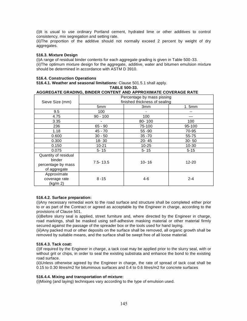
(i)It is usual to use ordinary Portland cement, hydrated lime or other additives to controlconsistency, mix segregation and setting rate.(ii)The proportion of the additive should not normally exceed 2 percent by weight of dryaggregates.
516.3. Mixture Design(i)A range of residual binder contents for each aggregate grading is given in Table 500-33.(ii)The optimum mixture design for the aggregate, additive, water and bitumen emulsion mixtureshould be determined in accordance with ASTM D 3910.
516.4. Construction Operations516.4.1. Weather and seasonal limitations: Clause 501.5.1 shall apply.
TABLE 500-33.AGGREGATE GRADING, BINDER CONTENT AND APPROXIMATE COVERAGE RATE
Sieve Size (mm)Percentage by mass pissingfinished thickness of sealing
5mm 3mm 1. 5mm9.5 100 - --
4.75 90 - 100 100 —3.35 - 80- 100 100236 65 - 90 75-100 95-1001.18 45 - 70 55 -90 70-95
0.600 30 - 50 35 -70 55-750.300 18- 30 20- 45 30- 500.150 10-21 10-25 10-300.075 5- 15 5- 15 5-15
Quantity of residualbinder
percentage by massof aggregate
7.5- 13.5 10- 16 12-20
Approximatecoverage rate
(kg/m 2)8 -15 4-6 2-4
516.4.2. Surface preparation:(i)Any necessary remedial work to the road surface and structure shall be completed either priorto or as part of the Contract or agreed as acceptable by the Engineer in charge, according to theprovisions of Clause 501.(ii)Before slurry seal is applied, street furniture and, where directed by the Engineer in charge,road markings, shall be masked using self-adhesive masking material or other material firmlysecured against the passage of the spreader box or the tools used for hand laying.(iii)Any packed mud or other deposits on the surface shall be removed, all organic growth shall beremoved by suitable means, and the surface shall be swept free of all loose material.
516.4.3. Tack coat:(i)If required by the Engineer in charge, a tack coat may be applied prior to the slurry seal, with orwithout grit or chips, in order to seal the existing substrata and enhance the bond to the existingroad surface.(ii)Unless otherwise agreed by the Engineer in charge, the rate of spread of tack coat shall be0.15 to 0.30 litres/m2 for bituminous surfaces and 0.4 to 0.6 litres/m2 for concrete surfaces
516.4.4. Mixing and transportation of mixture:(i)Mixing (and laying) techniques vary according to the type of emulsion used.
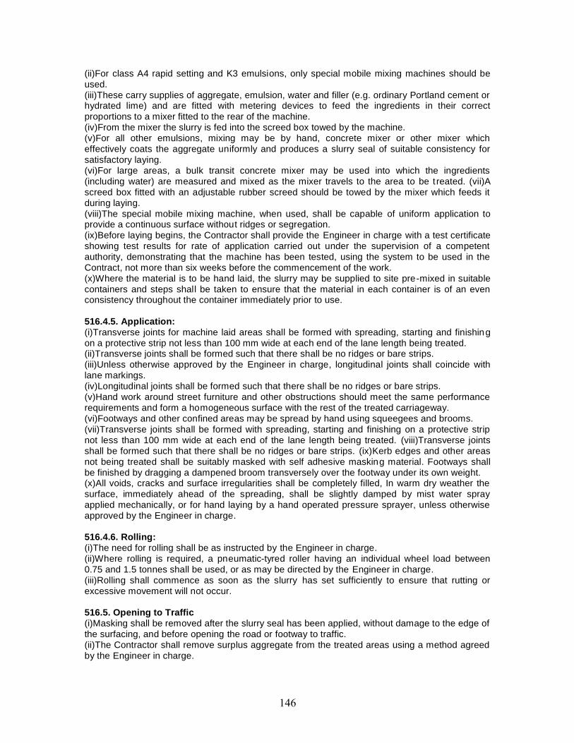
(ii)For class A4 rapid setting and K3 emulsions, only special mobile mixing machines should beused.(iii)These carry supplies of aggregate, emulsion, water and filler (e.g. ordinary Portland cement orhydrated lime) and are fitted with metering devices to feed the ingredients in their correctproportions to a mixer fitted to the rear of the machine.(iv)From the mixer the slurry is fed into the screed box towed by the machine.(v)For all other emulsions, mixing may be by hand, concrete mixer or other mixer whicheffectively coats the aggregate uniformly and produces a slurry seal of suitable consistency forsatisfactory laying.(vi)For large areas, a bulk transit concrete mixer may be used into which the ingredients(including water) are measured and mixed as the mixer travels to the area to be t reated. (vii)Ascreed box fitted with an adjustable rubber screed should be towed by the mixer which feeds itduring laying.(viii)The special mobile mixing machine, when used, shall be capable of uniform application toprovide a continuous surface without ridges or segregation.(ix)Before laying begins, the Contractor shall provide the Engineer in charge with a test certificateshowing test results for rate of application carried out under the supervision of a competentauthority, demonstrating that the machine has been tested, using the system to be used in theContract, not more than six weeks before the commencement of the work.(x)Where the material is to be hand laid, the slurry may be supplied to site pre-mixed in suitablecontainers and steps shall be taken to ensure that the material in each container is of an evenconsistency throughout the container immediately prior to use.
516.4.5. Application:(i)Transverse joints for machine laid areas shall be formed with spreading, starting and finishingon a protective strip not less than 100 mm wide at each end of the lane length being treated.(ii)Transverse joints shall be formed such that there shall be no ridges or bare strips.(iii)Unless otherwise approved by the Engineer in charge, longitudinal joints shall coincide withlane markings.(iv)Longitudinal joints shall be formed such that there shall be no ridges or bare strips.(v)Hand work around street furniture and other obstructions should meet the same performancerequirements and form a homogeneous surface with the rest of the treated carriageway.(vi)Footways and other confined areas may be spread by hand using squeegees and brooms.(vii)Transverse joints shall be formed with spreading, starting and finishing on a protective stripnot less than 100 mm wide at each end of the lane length being treated. (viii)Transverse jointsshall be formed such that there shall be no ridges or bare strips. (ix)Kerb edges and other areasnot being treated shall be suitably masked with self adhesive masking material. Footways shallbe finished by dragging a dampened broom transversely over the footway under its own weight.(x)All voids, cracks and surface irregularities shall be completely filled, In warm dry weather thesurface, immediately ahead of the spreading, shall be slightly damped by mist water sprayapplied mechanically, or for hand laying by a hand operated pressure sprayer, unless otherwiseapproved by the Engineer in charge.
516.4.6. Rolling:(i)The need for rolling shall be as instructed by the Engineer in charge.(ii)Where rolling is required, a pneumatic-tyred roller having an individual wheel load between0.75 and 1.5 tonnes shall be used, or as may be directed by the Engineer in charge.(iii)Rolling shall commence as soon as the slurry has set sufficiently to ensure that rutting orexcessive movement will not occur.
516.5. Opening to Traffic(i)Masking shall be removed after the slurry seal has been applied, without damage to the edge ofthe surfacing, and before opening the road or footway to traffic.(ii)The Contractor shall remove surplus aggregate from the treated areas using a method agreedby the Engineer in charge.
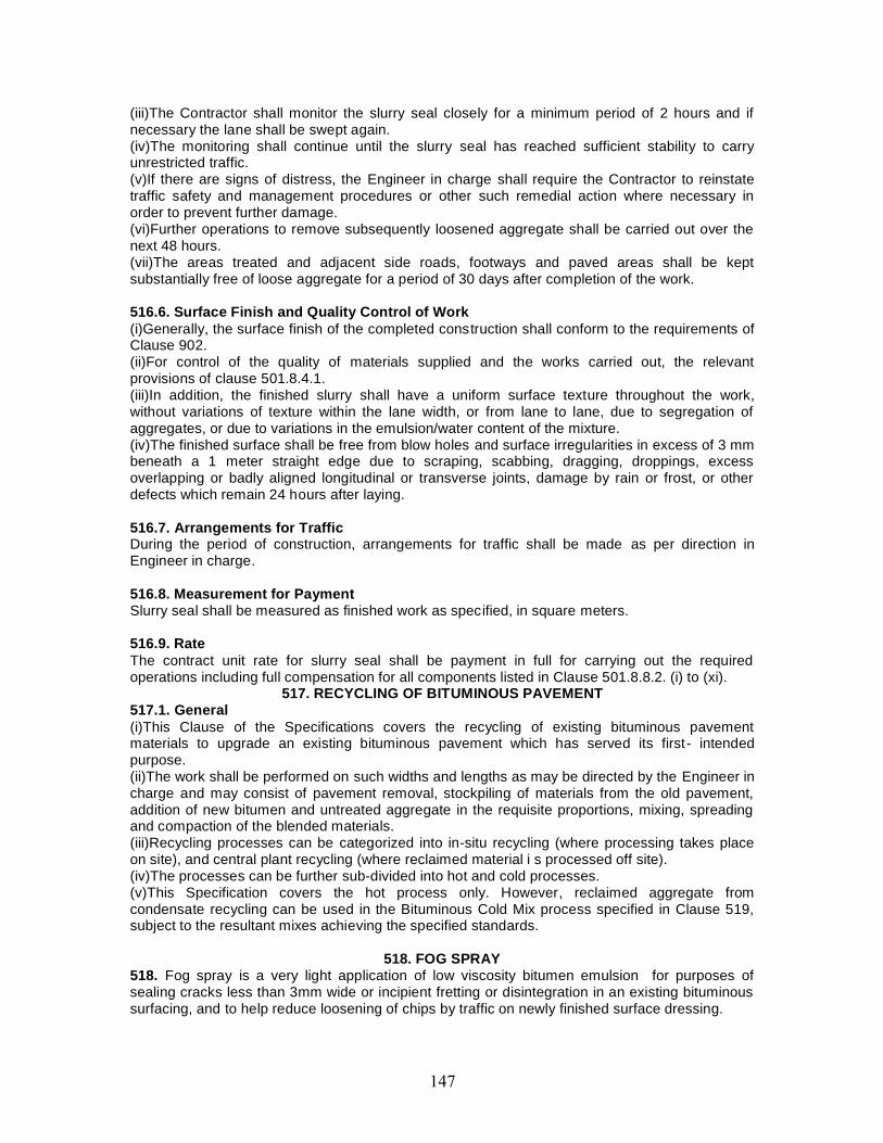
(iii)The Contractor shall monitor the slurry seal closely for a minimum period of 2 hours and ifnecessary the lane shall be swept again.(iv)The monitoring shall continue until the slurry seal has reached sufficient stability to carryunrestricted traffic.(v)If there are signs of distress, the Engineer in charge shall require the Contractor to reinstatetraffic safety and management procedures or other such remedial action where necessary inorder to prevent further damage.(vi)Further operations to remove subsequently loosened aggregate shall be carried out over thenext 48 hours.(vii)The areas treated and adjacent side roads, footways and paved areas shall be keptsubstantially free of loose aggregate for a period of 30 days after completion of the work.
516.6. Surface Finish and Quality Control of Work(i)Generally, the surface finish of the completed construction shall conform to the requirements ofClause 902.(ii)For control of the quality of materials supplied and the works carried out, the relevantprovisions of clause 501.8.4.1.(iii)In addition, the finished slurry shall have a uniform surface texture throughout the work,without variations of texture within the lane width, or from lane to lane, due to segregation ofaggregates, or due to variations in the emulsion/water content of the mixture.(iv)The finished surface shall be free from blow holes and surface irregularities in excess of 3 mmbeneath a 1 meter straight edge due to scraping, scabbing, dragging, droppings, excessoverlapping or badly aligned longitudinal or transverse joints, damage by rain or frost, or otherdefects which remain 24 hours after laying.
516.7. Arrangements for TrafficDuring the period of construction, arrangements for traffic shall be made as per direction inEngineer in charge.
516.8. Measurement for PaymentSlurry seal shall be measured as finished work as specified, in square meters.
516.9. RateThe contract unit rate for slurry seal shall be payment in full for carrying out the requiredoperations including full compensation for all components listed in Clause 501.8.8.2. (i) to (xi).
517. RECYCLING OF BITUMINOUS PAVEMENT517.1. General(i)This Clause of the Specifications covers the recycling of existing bituminous pavementmaterials to upgrade an existing bituminous pavement which has served its first- intendedpurpose.(ii)The work shall be performed on such widths and lengths as may be directed by the Engineer incharge and may consist of pavement removal, stockpiling of materials from the old pavement,addition of new bitumen and untreated aggregate in the requisite proportions, mixing, spreadingand compaction of the blended materials.(iii)Recycling processes can be categorized into in-situ recycling (where processing takes placeon site), and central plant recycling (where reclaimed material i s processed off site).(iv)The processes can be further sub-divided into hot and cold processes.(v)This Specification covers the hot process only. However, reclaimed aggregate fromcondensate recycling can be used in the Bituminous Cold Mix process specified in Clause 519,subject to the resultant mixes achieving the specified standards.
518. FOG SPRAY518. Fog spray is a very light application of low viscosity bitumen emulsion for purposes ofsealing cracks less than 3mm wide or incipient fretting or disintegration in an existing bituminoussurfacing, and to help reduce loosening of chips by traffic on newly finished surface dressing.
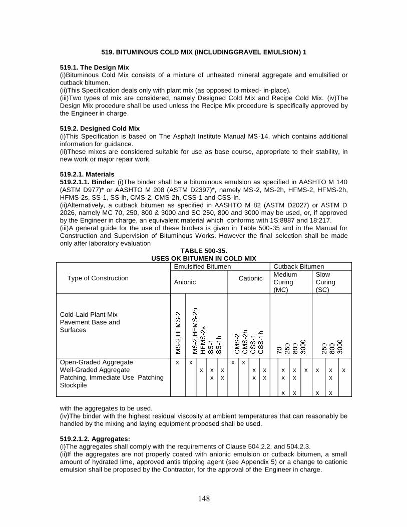
519. BITUMINOUS COLD MIX (INCLUDINGGRAVEL EMULSION) 1
519.1. The Design Mix(i)Bituminous Cold Mix consists of a mixture of unheated mineral aggregate and emulsified orcutback bitumen.(ii)This Specification deals only with plant mix (as opposed to mixed- in-place).(iii)Two types of mix are considered, namely Designed Cold Mix and Recipe Cold Mix. (iv)TheDesign Mix procedure shall be used unless the Recipe Mix procedure is specifically approved bythe Engineer in charge.
519.2. Designed Cold Mix(i)This Specification is based on The Asphalt Institute Manual MS-14, which contains additionalinformation for guidance.(ii)These mixes are considered suitable for use as base course, appropriate to their stability, innew work or major repair work.
519.2.1. Materials519.2.1.1. Binder: (i)The binder shall be a bituminous emulsion as specified in AASHTO M 140(ASTM D977)* or AASHTO M 208 (ASTM D2397)*, namely MS-2, MS-2h, HFMS-2, HFMS-2h,HFMS-2s, SS-1, SS-lh, CMS-2, CMS-2h, CSS-1 and CSS-In.(ii)Alternatively, a cutback bitumen as specified in AASHTO M 82 (ASTM D2027) or ASTM D2026, namely MC 70, 250, 800 & 3000 and SC 250, 800 and 3000 may be used, or, if approvedby the Engineer in charge, an equivalent material which conforms with 1S:8887 and 18:217.(iii)A general guide for the use of these binders is given in Table 500-35 and in the Manual forConstruction and Supervision of Bituminous Works. However the final selection shall be madeonly after laboratory evaluation
TABLE 500-35.USES OK BITUMEN IN COLD MIX
Type of Construction
Emulsified Bitumen Cutback Bitumen
Anionic Cationic MediumCuring(MC)
SlowCuring(SC)
Cold-Laid Plant MixPavement Base andSurfaces
Open-Graded AggregateWell-Graded AggregatePatching, Immediate Use PatchingStockpile
x xx x
xxx
x xxx
xx
xx
x
xx
x
x x
x
xx
x
x
with the aggregates to be used.(iv)The binder with the highest residual viscosity at ambient temperatures that can reasonably behandled by the mixing and laying equipment proposed shall be used.
519.2.1.2. Aggregates:(i)The aggregates shall comply with the requirements of Clause 504.2.2. and 504.2.3.(ii)If the aggregates are not properly coated with anionic emulsion or cutback bitumen, a smallamount of hydrated lime, approved antis tripping agent (see Appendix 5) or a change to cationicemulsion shall be proposed by the Contractor, for the approval of the Engineer in charge.
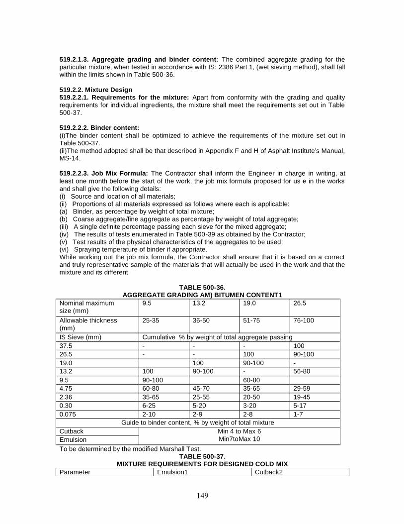
519.2.1.3. Aggregate grading and binder content: The combined aggregate grading for theparticular mixture, when tested in accordance with IS: 2386 Part 1, (wet sieving method), shall fallwithin the limits shown in Table 500-36.
519.2.2. Mixture Design519.2.2.1. Requirements for the mixture: Apart from conformity with the grading and qualityrequirements for individual ingredients, the mixture shall meet the requirements set out in Table500-37.
519.2.2.2. Binder content:(i)The binder content shall be optimized to achieve the requirements of the mixture set out inTable 500-37.(ii)The method adopted shall be that described in Appendix F and H of Asphalt Institute’s Manual,MS-14.
519.2.2.3. Job Mix Formula: The Contractor shall inform the Engineer in charge in writing, atleast one month before the start of the work, the job mix formula proposed for us e in the worksand shall give the following details:(i) Source and location of all materials;(ii) Proportions of all materials expressed as follows where each is applicable:(a) Binder, as percentage by weight of total mixture;(b) Coarse aggregate/fine aggregate as percentage by weight of total aggregate;(iii) A single definite percentage passing each sieve for the mixed aggregate;(iv) The results of tests enumerated in Table 500-39 as obtained by the Contractor;(v) Test results of the physical characteristics of the aggregates to be used;(vi) Spraying temperature of binder if appropriate.While working out the job mix formula, the Contractor shall ensure that it is based on a correctand truly representative sample of the materials that will actually be used in the work and that themixture and its different
TABLE 500-36.AGGREGATE GRADING AM) BITUMEN CONTENT1
Nominal maximumsize (mm)
9.5 13.2 19.0 26.5
Allowable thickness(mm)
25-35 36-50 51-75 76-100
IS Sieve (mm) Cumulative % by weight of total aggregate passing37.5 - - - 10026.5 - - 100 90-10019.0 100 90-100 -13.2 100 90-100 - 56-809.5 90-100 60-804.75 60-80 45-70 35-65 29-592.36 35-65 25-55 20-50 19-450.30 6-25 5-20 3-20 5-170.075 2-10 2-9 2-8 1-7
Guide to binder content, % by weight of total mixtureCutback Min 4 to Max 6
Min7toMax 10EmulsionTo be determined by the modified Marshall Test.
TABLE 500-37.MIXTURE REQUIREMENTS FOR DESIGNED COLD MIX
Parameter Emulsion1 Cutback2
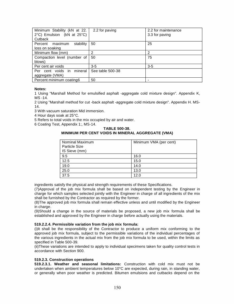
Minimum Stability (kN at 22.2°C) Emulsion (kN at 25"C)Cutback
2.2 for paving 2.2 for maintenance3.3 for paving
Percent maximum stabilityloss on soaking
50 25
Minimum flow (mm) 2 2Compaction level (number ofblows)
50 75
Per cent air voids 3-5 3-5Per cent voids in mineralaggregate (VMA)
See table 500-38
Percent minimum coating6 50 -
Notes:1 Using "Marshall Method for emulsified asphalt -aggregate cold mixture design". Appendix K,MS -14.2 Using "Marshall method for cut -back asphalt -aggregate cold mixture design". Appendix H. MS-14.3 With vacuum saturation Mid immersion.4 Hour days soak at 25°C.5 Refers to total voids in the mix occupied by air and water.6 Coating Test, Appendix 1;, MS-14.
TABLE 500-38.MINIMUM PER CENT VOIDS IN MINERAL AGGREGATE (VMA)
Nominal MaximumParticle SizeIS Sieve (mm)
Minimum VMA (per cent)
9.5 16.012.5 15.019.0 14.025.0 13.037.5 12.0
ingredients satisfy the physical and strength requirements of these Specifications.(7)Approval of the job mix formula shall be based on independent testing by the Engineer incharge for which samples selected jointly with the Engineer in charge of all ingredients of the mixshall be furnished by the Contractor as required by the former.(8)The approved job mix formula shall remain effective unless and until modified by the Engineerin charge.(9)Should a change in the source of materials be proposed, a new job mix formula shall beestablished and approved by the Engineer in charge before actually using the materials.
519.2.2.4. Permissible variation from the job mix formula:(i)It shall be the responsibility of the Contractor to produce a uniform mix conforming to theapproved job mix formula, subject to the permissible variations of the individual percentages ofthe various ingredients in the actual mix from the job mix formula to be used, within the limits asspecified in Table 500-39.(ii)These variations are intended to apply to individual specimens taken for quality control tests inaccordance with Section 900.
519.2.3. Construction operations519.2.3.1. Weather and seasonal limitations: Construction with cold mix must not beundertaken when ambient temperatures below 10°C are expected, during rain, in standing water,or generally when poor weather is predicted. Bitumen emulsions and cutbacks depend on the
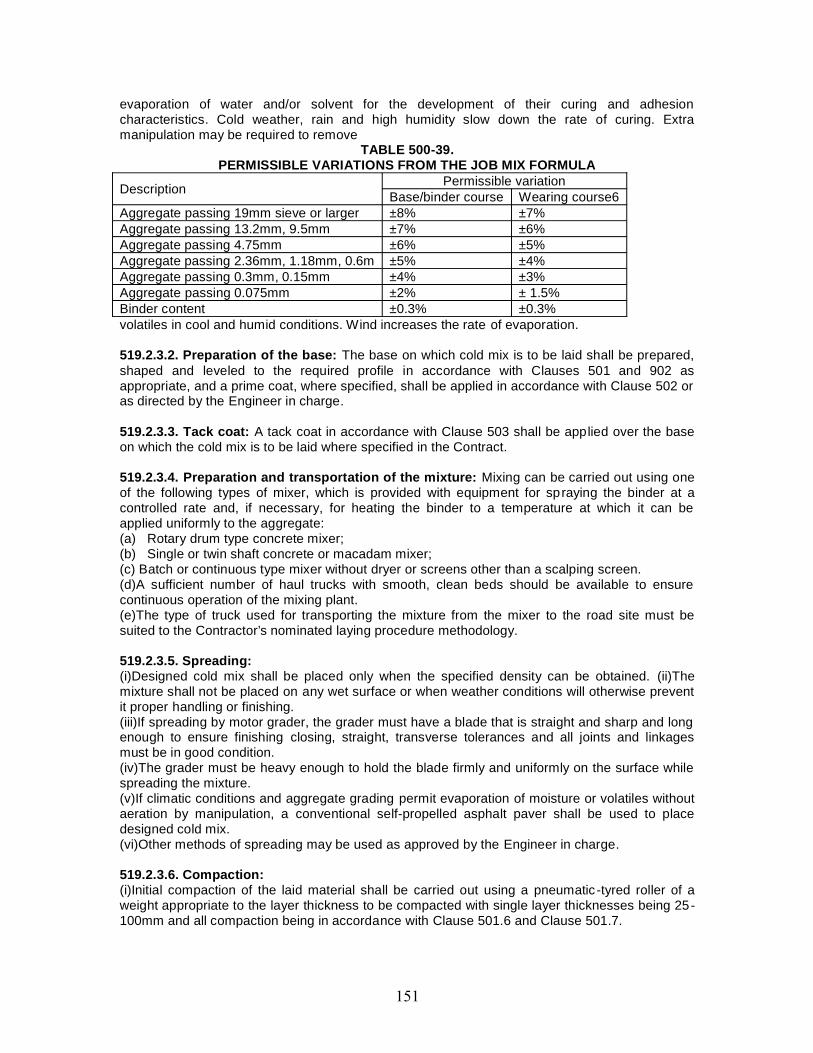
evaporation of water and/or solvent for the development of their curing and adhesioncharacteristics. Cold weather, rain and high humidity slow down the rate of curing. Extramanipulation may be required to remove
TABLE 500-39.PERMISSIBLE VARIATIONS FROM THE JOB MIX FORMULA
Description Permissible variationBase/binder course Wearing course6
Aggregate passing 19mm sieve or larger ±8% ±7%Aggregate passing 13.2mm, 9.5mm ±7% ±6%Aggregate passing 4.75mm ±6% ±5%Aggregate passing 2.36mm, 1.18mm, 0.6m ±5% ±4%Aggregate passing 0.3mm, 0.15mm ±4% ±3%Aggregate passing 0.075mm ±2% ± 1.5%Binder content ±0.3% ±0.3%volatiles in cool and humid conditions. Wind increases the rate of evaporation.
519.2.3.2. Preparation of the base: The base on which cold mix is to be laid shall be prepared,shaped and leveled to the required profile in accordance with Clauses 501 and 902 asappropriate, and a prime coat, where specified, shall be applied in accordance with Clause 502 oras directed by the Engineer in charge.
519.2.3.3. Tack coat: A tack coat in accordance with Clause 503 shall be applied over the baseon which the cold mix is to be laid where specified in the Contract.
519.2.3.4. Preparation and transportation of the mixture: Mixing can be carried out using oneof the following types of mixer, which is provided with equipment for spraying the binder at acontrolled rate and, if necessary, for heating the binder to a temperature at which it can beapplied uniformly to the aggregate:(a) Rotary drum type concrete mixer;(b) Single or twin shaft concrete or macadam mixer;(c) Batch or continuous type mixer without dryer or screens other than a scalping screen.(d)A sufficient number of haul trucks with smooth, clean beds should be available to ensurecontinuous operation of the mixing plant.(e)The type of truck used for transporting the mixture from the mixer to the road site must besuited to the Contractor’s nominated laying procedure methodology.
519.2.3.5. Spreading:(i)Designed cold mix shall be placed only when the specified density can be obtained. (ii)Themixture shall not be placed on any wet surface or when weather conditions will otherwise preventit proper handling or finishing.(iii)If spreading by motor grader, the grader must have a blade that is straight and sharp and longenough to ensure finishing closing, straight, transverse tolerances and all joints and linkagesmust be in good condition.(iv)The grader must be heavy enough to hold the blade firmly and uniformly on the surface whilespreading the mixture.(v)If climatic conditions and aggregate grading permit evaporation of moisture or volatiles withoutaeration by manipulation, a conventional self-propelled asphalt paver shall be used to placedesigned cold mix.(vi)Other methods of spreading may be used as approved by the Engineer in charge.
519.2.3.6. Compaction:(i)Initial compaction of the laid material shall be carried out using a pneumatic -tyred roller of aweight appropriate to the layer thickness to be compacted with single layer thicknesses being 25-100mm and all compaction being in accordance with Clause 501.6 and Clause 501.7.
(ii)Smooth tyres shall be used. Final rolling and smoothing of the surface should be completedusing steel wheel rollers.(iii)The Contractor shall demonstrate at laying trials that his proposed laying and compactionmethods can achieve a satisfactory result.
519.2.4. Opening to traffic:(i)Traffic shall not be allowed to run on new work until all the water or volatiles in the mixture haveevaporated, as determined by the Engineer in charge.(ii)The rate of evaporation will be influenced by the temperature, humidity and wind conditions.
519.2.5. Surface finish and quality control of work:(i)The surface finish of construction shall conform to the requirements of Clause 902.(ii)For control of the quality of supplied materials and the works carried out, the relevantprovisions of clause 501.8.4.1.
519.2.6. Arrangements for traffic: During the period of construction, arrangements for trafficshall be made as per in the direction of Engineer in charge.
519.2.7. Measurement for payment: Designed Cold Mix shall be measured as finished work, forthe area covered, in cubic meters, by weight in metric tonnes, or by square meters at a specifiedthickness as specified in the Contract.
519.2.8. Rate:(i)The contract unit rate for Designed Cold Mix shall be payment in full for carrying out therequired operations including full compensation for all components listed in Clause 501.8.8.2. (i)to (xi).(ii)The rate shall cover the provision of the specified grade of cutback in the mix at 5 per cent ofthe weight of the total mix or emulsion at 8 per cent of the weight of the total mix, with theprovision that the variation of quantity of binder will be assessed on the basis of the amountagreed by the Engineer in charge and the payment adjusted as per the rate for cutback oremulsion quoted in the Bill of Quantities. Recipe Cold Mix
Recipe Cold Mix519.3. Recipe Cold Mix(i)This Specification is based on BS434: Part 2:1984 which contains additional information.(ii)These are premixes made with emulsion binder which are laid immediately after mixing andwhile the emulsion is still substantially in an unbroken state.(iii)These mixes are considered suitable for use only for emergency and minor repair work andtemporary road surface improvement.
519.3.1. Materials519.3.1.1. Binder:(i)Emulsions of sufficient stability for mixing with the particular graded aggregate should be used.(ii)Grades of emulsion quoted are in accordance with BS434: Part 1:1984 but comparable gradesto IS or AASHTO specifications may be used.(iii)Guidance on selection of an appropriate grade of emulsion is given in the Manual forConstruction and Supervision of Bituminous Works.(iv)The corresponding grades in IS: 8887 are only broadly classified as RS, MS and SS andfurther sub- classification is not available at present.
519.3.1.2. Aggregates:(i)Any normal, clean, but not necessarily dry, aggregate can be used, provided that it has asufficiently high crushing strength with regard to the traffic to be earned. Typical grading is givenin Table 500-40.
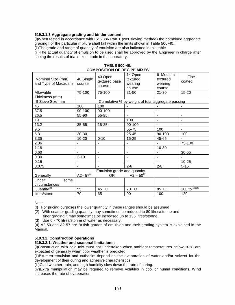
519.3.1.3 Aggregate grading and binder content:(i)When tested in accordance with IS: 2386 Part 1 (wet sieving method) the combined aggregategrading f or the particular mixture shall fall within the limits shown in Table 500-40.(ii)The grade and range of quantity of emulsion are also indicated in this table.(iii)The actual quantity of emulsion to be used shall be approved by the Engineer in charge afterseeing the results of trial mixes made in the laboratory.
TABLE 500-40.COMPOSITION OF RECIPE MIXES
Nominal Size (mm)and Type of Macadam
40 Singlecourse
40 Opentextured basecourse
14 Opentexturedwearingcourse
6 Mediumtexturedwearingcourse
Finecoated
AllowableThickness (mm)
75-100 75-100 31-50 21-30 15-20
IS Sieve Size mm Cumulative % by weight of total aggregate passing45 100 100 - - -37.5 90-100 90-100 - - -26.5 55-90 55-85 - - -19 100 - -13.2 35-55 15-35 90-100 - -9.5 55-75 100 -6.3 20-30 25-45 90-100 1003.35 10-20 0-10 15-25 45-65 -2.36 - - - - 75-1001.18 - - - 10-30 -0.60 - - - - 30-550.30 2-10 - - - -0.15 - - - - 10-250.075 - - 2-6 2-8 5-15
Emulsion grade and quantityGenerally A2– 57(4) OR A2 – 50(4)
Under somecircumstancesQuantity(1) 55 45 TO 70 TO 85 TO 100 to (2)(3)
liters/stone 70 65 90 100 120
Note:(l) For pricing purposes the lower quantity in these ranges should be assumed(2) With coarser grading quantity may sometimes be reduced to 80 lilres/stonne and
finer grading it may sometimes be increased up to 135 litres/stonne.(3) Use 0 - 70 litres/stonne of water as necessary.(4) A2-50 and A2-57 are British grades of emulsion and their grading system is explained in theManual.
519.3.2. Construction operations519.3.2.1. Weather and seasonal limitations:(i)Construction with cold mix must not undertaken when ambient temperatures below 10°C areexpected of generally when poor weather is predicted.(ii)Bitumen emulsion and cutbacks depend on the evaporation of water and/or solvent for thedevelopment of their curing and adhesive characteristics.(iii)Cold weather, rain, and high humidity slow down the rate of curing.(iv)Extra manipulation may be required to remove volatiles in cool or humid conditions. Windincreases the rate of evaporation.
519.3.2.2. Preparation of base: The base on which the cold mix is to be laid shall be preparedshaped and graded to the required profile in accordance with Clauses 501 and 902 asappropriate, and a prime coat if specified in the contract, or required by the Engineer in charge,shall be applied in accordance with Clause 502, or as directed by the Engineer in charge.
519.3.2.3. Tack coat: A tack coat in accordance with Clause 503 shall be applied over the baseon which the cold mix is to be laid if specified in the Contract or required by the Engineer incharge.
519.3.2.4. Preparation and transportation of the mixture: Mixing shall be carried out using oneof the following types of mixer, which is provided with equipment for spraying the binder at acontrolled rate, and, if necessary, for heating the binder to a temperature at which it can beapplied uniformly to the aggregate:(a) Rotary drum type concrete mixer,(b) Single or twin shaft concrete or macadam mixer,(c) Batch or continuous type mixer without dryer or screens other than a scalping screen.
A sufficient number of haul trucks with smooth, clean beds should be available to ensurecontinuous operation of the mixing plant. The type of truck used for transporting the mixture fromthe mixer to the road site must be suited to the chosen laying procedure.
519.3.2.5. Spreading:(i)The mixed material should be spread immediately after preparation.(ii)The mixture shall be placed only when the specified density can be obtained.(iii)The mixture shall not be placed on any wet surface or when weather conditions will otherwiseprevent its proper handling or finishing.(iv)If spreading by motor grader, the grader must have a blade that is straight and sharp and longenough to ensure finishing closing straight transverse tolerances and all joints and linkages mustbe in good condition.(v)The grader must be heavy enough to hold the blade firmly and uniformly on the surface whilespreading the mixture. On surface courses, the tyres must be smooth.(vi)The methodology for spreading shall be approved by the Engineer in charge prior to laying,and if required a laying trial conducted to prove the laying method satisfactory before approval.
519.3.2.6. Compaction:(i)Initial compaction of the laid material shall be carried out using a pneumatic -tyred roller of aweight appropriate to the layer thickness to be compacted with single layer thicknesses being 25-100mm and all compaction being in accordance with Clause 501.6 and 501.7.(ii)Smooth tyres shall be used. Final rolling and smoothing of the surface should be completedusing steel wheel rollers.(iii)The Contractor shall demonstrate at laying trials that his proposed laying and compactionmethods can achieve a satisfactory result.
519.3.3. Opening to traffic:(i)Traffic shall not be allowed to run on new work until all the water or volatiles in the mixture haveevaporated.(ii)The rate of evaporation will be influenced by the temperature, humidity and wind conditions.
519.3.4. Surface finish and quality control of work:(i)The surface finish of construction shall conform to the requirements of Clause 902.(ii)For control of the quality of materials supplied and the works carried out, the relevantprovisions of clause of 501.8.4.1.
519.3.5. Arrangements for traffic: During the period of construction, arrangements for trafficshall be made as per direction Engineer in charge.
519.3.6. Measurement for payment: Recipe Cold Mix shall be measured as finished work, forthe area instructed to be covered, in cubicmetres, by weight in metric tonnes, or in square mete rsat a specified thickness, as specified in the Contract.
519.3.7. Rate(i)The contract unit rate for Recipe Cold Mix shall be payment in full for carrying out the requiredoperations including full compensation for all components listed in Clause 501.8.8.2. (i) to (xi).(ii)The rate shall cover the provision of the specified grade of emulsion at the lower quantity in therange for each type of mix indicated in Table 500-44 with the provision that the variation ofquantity of emulsion will be assessed on the basis of the amount agreed by the Engineer incharge and the payment adjusted as per the rate for emulsion quoted in the Bill of Quantities.
520. SAND ASPHALT BASE COURSE1520.1. GeneralThis work shall consist of a base course composed of a mixture of sand, mineral filler whererequired and bituminous binder, placed and compacted upon a prepared and accepted sub gradein accordance with these Specifications and the lines, levels, grades dimensions and crosssections shown on the Drawings or as directed by the Engineer in charge,
521. MODIFIED BINDER1521.1. General(i)Modified binders comprise a base binder, to which is added either natural rubber, crumb rubberor a polymer such as Styrene- Butadiene- Styrene (SBS), Ethylene-Vinyl-Acetate (EVA) or LowDensity Polyethylene (LDPE).(ii)The purpose is to achieve a high performance binder with improved properties, particularly atextremes of temperature.
521.2. Materials521.2.1. Base Binder:(i)The base binder into which the modifier is incorporated shall conform to IS: 73.(ii)The choice of grade shall be such that it is compatible with the modifier and, when mixed shallhave the properties described in Clause 521.3.
521.2.2. Modifier:(i)The modifier shall be a natural rubber, crumb rubber or any other polymer which is compatiblewith >he base binder and which allows the properties given in Clause 521.3 to be achieved Forfurther details, IRC:SP:53-1999 may be referred to.(ii)The modifier, in the required quantity shall be blended at the refinery or at the site plan:capable of producing modified binder.
521.3. Modifier Proportions(i)The quantity of modifier to be added shall be determined by tests on the base binder and themodified binder and the properties desired.(ii)A reference may be made to the Manual for Construction and Supervision of Bituminous Worksfor indicative dosage of different types of modifiers.(iii)The properties of the modified binder shall be as given in Table 500-44, 500-45 or 500-46according to the requirement of the Contract.
521.4. Mixing(i)The modifier shall be blended with the base binder so that it disperses thoroughly prior to use.(ii)The type of mixing equipment used shall be suited to the modifier type.(iii)Further guidance is given in the Manual for Construction and Supervision of BituminousWorks.
521.5. Quality Control of Materials
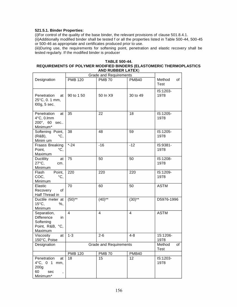
521.5.1. Binder Properties:(i)For control of the quality of the base binder, the relevant provisions of clause 501.8.4.1.(ii)Additionally modified binder shall be tested f or all the properties listed in Table 500-44, 500-45or 500-46 as appropriate and certificates produced prior to use.(iii)During use, the requirements for softening point, penetration and elastic recovery shall betested regularly. If the modified binder is producer
TABLE 500-44.REQUIREMENTS OF POLYMER MODIFIED BINDERS (ELASTOMERIC THERMOPLASTICS
AND RUBBER LATEX)
DesignationGrade and Requirements
Method ofTest
PMB 120 PMB 70 PMB40
Penetration at25°C, 0. 1 mm,l00g, 5 sec.
90 to 1 50 50 In X9 30 to 49IS:1203-1978
Penetration at4°C, 0.lmm200°, 60 sec..Minimum*
35 22 18 IS:1205-1978
Softening Point,(R&B), °C,Minim um
38 48 59 IS:1205-1978
Fraass BreakingPoint, °C,Maximum
*-24 -16 -12 IS:9381-1978
Ductility at27°C, cm.Minimum
75 50 50 IS:1208-1978
Flash Point,COC, °C,Minimum
220 220 220 IS:1209-1978
ElasticRecovery ofHalf Thread in
70 60 50 ASTM
Ductile meter at15°C, %,Minimum
(50)** (40)** (30)** D5976-1996
Separation,Difference inSofteningPoint, R&B, °C,Maximum
4 4 4 ASTM
Viscosity at150°C, Poise
1-3 2-6 4-8 15:1206-1978
Designation Grade and Requirements Method ofTest
PMB 120 PMB 70 PMB40Penetration at4°C, 0 1 mm,200g60 sec ,Minimum*
18 15 12 IS:1203-1978
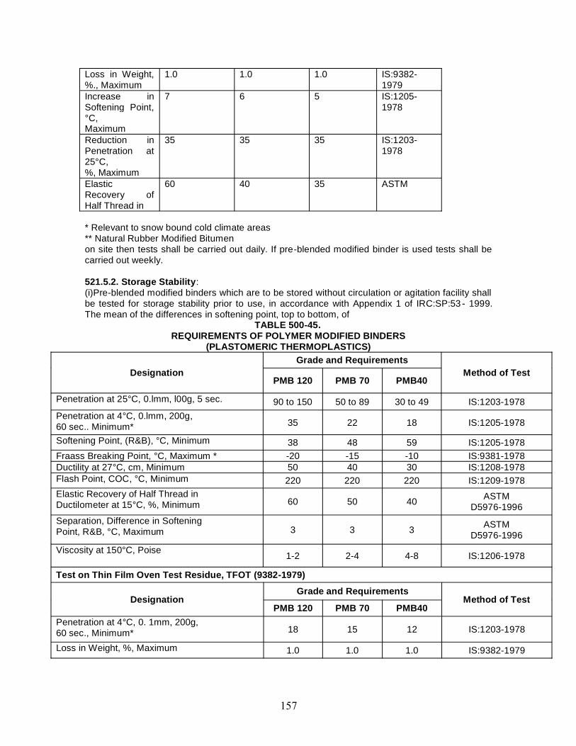
Loss in Weight,%., Maximum
1.0 1.0 1.0 IS:9382-1979
Increase inSoftening Point,°C,Maximum
7 6 5 IS:1205-1978
Reduction inPenetration at25°C,%, Maximum
35 35 35 IS:1203-1978
ElasticRecovery ofHalf Thread in
60 40 35 ASTM
* Relevant to snow bound cold climate areas** Natural Rubber Modified Bitumenon site then tests shall be carried out daily. If pre-blended modified binder is used tests shall becarried out weekly.
521.5.2. Storage Stability:(i)Pre-blended modified binders which are to be stored without circulation or agitation facility shallbe tested for storage stability prior to use, in accordance with Appendix 1 of IRC:SP:53 - 1999.The mean of the differences in softening point, top to bottom, of
TABLE 500-45.REQUIREMENTS OF POLYMER MODIFIED BINDERS
(PLASTOMERIC THERMOPLASTICS)
DesignationGrade and Requirements
Method of TestPMB 120 PMB 70 PMB40
Penetration at 25°C, 0.lmm, l00g, 5 sec. 90 to 150 50 to 89 30 to 49 IS:1203-1978Penetration at 4°C, 0.lmm, 200g,60 sec.. Minimum* 35 22 18 IS:1205-1978
Softening Point, (R&B), °C, Minimum 38 48 59 IS:1205-1978Fraass Breaking Point, °C, Maximum * -20 -15 -10 IS:9381-1978Ductility at 27°C, cm, Minimum 50 40 30 IS:1208-1978Flash Point, COC, °C, Minimum 220 220 220 IS:1209-1978Elastic Recovery of Half Thread inDuctilometer at 15°C, %, Minimum 60 50 40 ASTM
D5976-1996Separation, Difference in SofteningPoint, R&B, °C, Maximum 3 3 3 ASTM
D5976-1996Viscosity at 150°C, Poise 1-2 2-4 4-8 IS:1206-1978
Test on Thin Film Oven Test Residue, TFOT (9382-1979)
DesignationGrade and Requirements
Method of TestPMB 120 PMB 70 PMB40
Penetration at 4°C, 0. 1mm, 200g,60 sec., Minimum* 18 15 12 IS:1203-1978
Loss in Weight, %, Maximum 1.0 1.0 1.0 IS:9382-1979
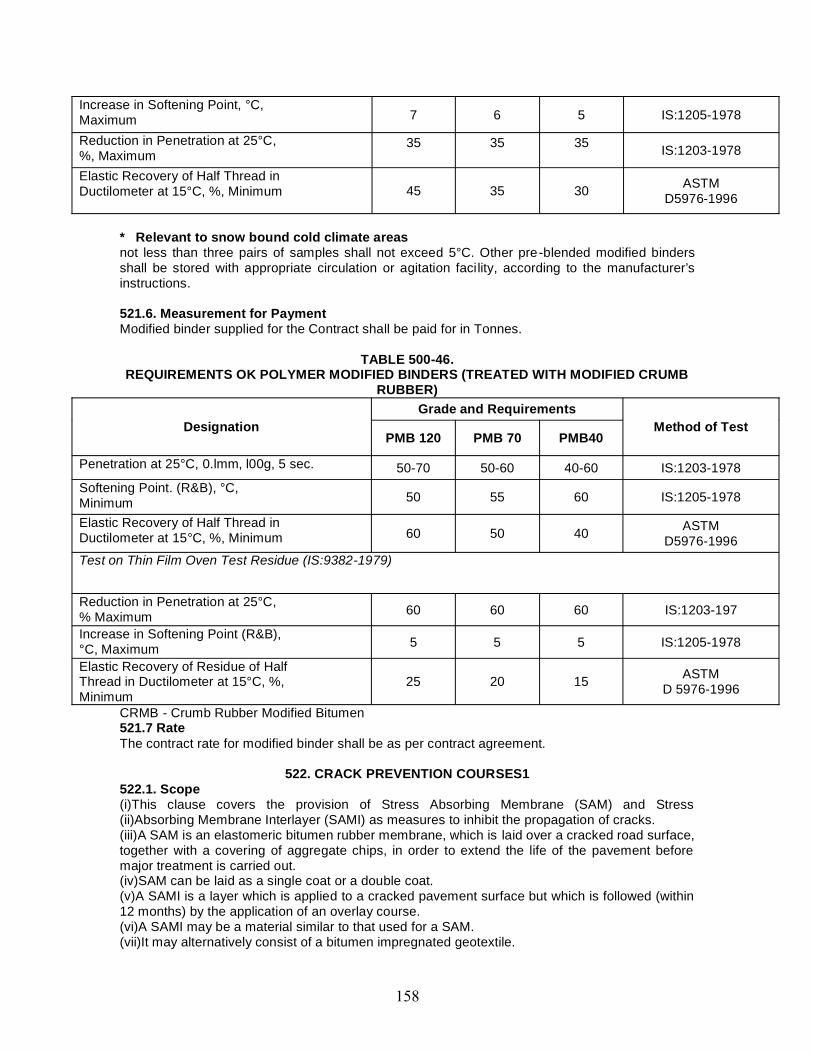
Increase in Softening Point, °C,Maximum 7 6 5 IS:1205-1978
Reduction in Penetration at 25°C,%, Maximum
35 35 35 IS:1203-1978
Elastic Recovery of Half Thread inDuctilometer at 15°C, %, Minimum 45 35 30 ASTM
D5976-1996
* Relevant to snow bound cold climate areasnot less than three pairs of samples shall not exceed 5°C. Other pre-blended modified bindersshall be stored with appropriate circulation or agitation facility, according to the manufacturer’sinstructions.
521.6. Measurement for PaymentModified binder supplied for the Contract shall be paid for in Tonnes.
TABLE 500-46.REQUIREMENTS OK POLYMER MODIFIED BINDERS (TREATED WITH MODIFIED CRUMB
RUBBER)
DesignationGrade and Requirements
Method of TestPMB 120 PMB 70 PMB40
Penetration at 25°C, 0.lmm, l00g, 5 sec. 50-70 50-60 40-60 IS:1203-1978Softening Point. (R&B), °C,Minimum 50 55 60 IS:1205-1978
Elastic Recovery of Half Thread inDuctilometer at 15°C, %, Minimum 60 50 40 ASTM
D5976-1996Test on Thin Film Oven Test Residue (IS:9382-1979)
Reduction in Penetration at 25°C,% Maximum 60 60 60 IS:1203-197
Increase in Softening Point (R&B),°C, Maximum 5 5 5 IS:1205-1978
Elastic Recovery of Residue of HalfThread in Ductilometer at 15°C, %,Minimum
25 20 15 ASTMD 5976-1996
CRMB - Crumb Rubber Modified Bitumen521.7 RateThe contract rate for modified binder shall be as per contract agreement.
522. CRACK PREVENTION COURSES1522.1. Scope(i)This clause covers the provision of Stress Absorbing Membrane (SAM) and Stress(ii)Absorbing Membrane Interlayer (SAMI) as measures to inhibit the propagation of cracks.(iii)A SAM is an elastomeric bitumen rubber membrane, which is laid over a cracked road surface,together with a covering of aggregate chips, in order to extend the life of the pavement beforemajor treatment is carried out.(iv)SAM can be laid as a single coat or a double coat.(v)A SAMI is a layer which is applied to a cracked pavement surface but which is followed (within12 months) by the application of an overlay course.(vi)A SAMI may be a material similar to that used for a SAM.(vii)It may alternatively consist of a bitumen impregnated geotextile.
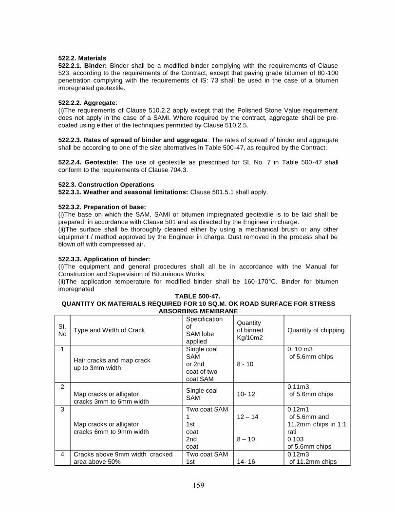
522.2. Materials522.2.1. Binder: Binder shall be a modified binder complying with the requirements of Clause523, according to the requirements of the Contract, except that paving grade bitumen of 80 -100penetration complying with the requirements of IS: 73 shall be used in the case of a bitumenimpregnated geotextile.
522.2.2. Aggregate:(i)The requirements of Clause 510.2.2 apply except that the Polished Stone Value requirementdoes not apply in the case of a SAMI. Where required by the contract, aggregate shall be pre-coated using either of the techniques permitted by Clause 510.2.5.
522.2.3. Rates of spread of binder and aggregate : The rates of spread of binder and aggregateshall be according to one of the size alternatives in Table 500-47, as required by the Contract.
522.2.4. Geotextile: The use of geotextile as prescribed for SI. No. 7 in Table 500-47 shallconform to the requirements of Clause 704.3.
522.3. Construction Operations522.3.1. Weather and seasonal limitations: Clause 501.5.1 shall apply.
522.3.2. Preparation of base:(i)The base on which the SAM, SAMI or bitumen impregnated geotextile is to be laid shall beprepared, in accordance with Clause 501 and as directed by the Engineer in charge.(ii)The surface shall be thoroughly cleaned either by using a mechanical brush or any otherequipment / method approved by the Engineer in charge. Dust removed in the process shall beblown off with compressed air.
522.3.3. Application of binder:(i)The equipment and general procedures shall all be in accordance with the Manual forConstruction and Supervision of Bituminous Works.(ii)The application temperature for modified binder shall be 160-170°C. Binder for bitumenimpregnated
TABLE 500-47.QUANTITY OK MATERIALS REQUIRED FOR 10 SQ.M. OK ROAD SURFACE FOR STRESS
ABSORBING MEMBRANE
SI.No Type and Width of Crack
SpecificationofSAM lobeapplied
Quantityof binnedKg/10m2
Quantity of chipping
1
Hair cracks and map crackup to 3mm width
Single coalSAMor 2ndcoat of twocoal SAM
8 - 10
0. 10 m3of 5.6mm chips
2Map cracks or alligatorcracks 3mm to 6mm width
Single coalSAM 10- 12
0.11m3of 5.6mm chips
3
Map cracks or alligatorcracks 6mm to 9mm width
Two coat SAM11stcoat2ndcoat
12 – 14
8 – 10
0.12m1of 5.6mm and
11.2mm chips in 1:1rati0.103of 5.6mm chips
4 Cracks above 9mm width crackedarea above 50%
Two coat SAM1st 14- 16
0.12m3of 11.2mm chips
coat2ndcoat
8 – 100.103of 5. 6mm chips
5All types of cracks withcrack width below 6mm
Single coatSAMas interlayer
8 – 10
0. 10 m3of 5.6mm chips
6 All types of cracks withcrack width above 6mm
Single coatSAMas interlayer
10 - 120.10m3of 11.2mm chips.
7 Bitumen ImpregnatedGeotextile
Note: 1 Binder quantities for bitumen impregnated geotextile shall be in the range 0.9 to 1.2Lures/nr. Binder quantities outside this range are permitted according to the geotextilemanufacturer’s instructions and subject to the agreement of the Engineer in charge. Geotextileshall be applied according to Clause 502.4. The surface on which the binder is to be applied shallbe dry.
522.3.4. Application of aggregates:(i)The equipment and general procedures shall all be in accordance with the Manual forConstruction and Supervision of Bituminous Works.(ii)Immediately after application of the modified binder, clean, dry aggregate shall be spreaduniformly on the surface.
522.3.5. Sweeping: The surface of SAMs and SAMIs shall be swept to ensure uniform spread ofaggregate and that there are no loose chips on the surface.
522.3.6. Two coat SAM or SAMI:(i)Where a two coat SAM or SAMI is required by the Contract, the second coat shall be appliedwithin 90 days of the first.
522.3.7. Geotextile placement: For bitumen impregnated geotextile, the requirements of Clause704.4.5 of the Ministry’s Specification for Road and Bridge Works (third revision) shall apply.
522.4. Opening to Traffic(i)Traffic may be permitted over a SAM or SAMI 2 hours after rolling but the speed shall be limitedto 20 km/h, until the following day.(ii)Speed control measures are to be approved by the Engineer in charge, prior to laying.
522.5. Surface Finish and Quality Control of Work(a)The surface finish shall conform to the requirements of Clause 902.(b)For control on the quality of materials supplied and the works carried out, the relevantprovisions of clause of 501.8.4.1.
522.6. Arrangements for Traffic(i)During the period of con struction, arrangements for traffic shall be made as per direction onEngineer in charge.
522.7. Measurement for Payment(i)Each application of SAM, SAMI or bitumen impregnated geotextile shall be measured asfinished work, for the area specified, in square meters.522.8. Rate(i)The contract unit rate for SAM, SAMI or bitumen impregnated geotextile shall be payment infull for carrying out the required operations including full compensation for all components listed inClause 501.8.8.2, (i) to (xi).


600 Concrete Pavements

CONTENT
Clause No Description601 DRY LEAN CEMENT CONCRETE SUB-BASE
602 CEMENT CONCRETE PAVEMENT
603 ROLLED CEMENT CONCRETE BASE
601. DRY LEAN CEMENT CONCRETE SUB-BASE601.1. Scope601.1.1. The work shall consist of construction of dry lean concrete sub base for cement concretepavement in accordance with the requirements of these Specifications and in conformity with thelines, grades and cross-sections shown on the drawings or as directed by the Engineer, The workshall include furnishing of all plant and equipment, materials and labour and performing alloperations, in connection with the work, as approved by the Engineer.
601.1.2. The design parameters of dry lean concrete sub-base, viz., width, thickness, grade ofconcrete, details of joints, if any, etc. shall be as stipulated in the Contract drawings.
601.2. Materials601.2.1. Source of Materials: The Contractor shall indicate to the Engineer the source of allmaterials with relevant test data to be used in the lean concrete work sufficiently in advance andthe approval of the Engineer for the same shall be obtained at least 45 days before the scheduledcommencement of the work. If the Contractor later proposes to obtain the materials from adifferent source, he shall notify the Engineer for his approval at least 45 days before suchmaterials are to be used.
601.2.2. Cement: Any of the following types of cement may be used with prior approval of theEngineer:
(i) Ordinary Portland cement IS: 269(ii) Portland Slag cement IS: 445(iij) Portland Poziolana cement IS: 1489
If the sub grade is found to consist of soluble sulphates in a concentration more than 0.5 per cent,cement used shall be sulphate resistant and shall conform to IS: 6909, cement to be used maypreferably be obtained in bulk form. It shall be stored in accordance with stipulations contained inClause 1014 and shall be subjected to acceptance test prior to its immediate use.
601.2.3. Aggregates:601.2.3.1. Aggregates for lean concrete shall be natural material complying with IS: 383. Theaggregates shall not be alkali reactive. The limits of deleterious materials shall not exceed therequirements set out in IS: 383. In case the Engineer considers that the aggregates are not freefrom din, the same may be washed and drained for at least 72 hours before batching, as directedby the Engineer.
601.2.3.2. Coarse aggregate: Coarse aggregate shall consist of clean, hard, strong, dense, non-porous and durable pieces of crushed stone or crushed gravel and shall be devoid of pieces ofdisintegrated stone, soft, flaky, elongated, very angular or splintery pieces. The maximum size ofthe coarse aggregate shall he 25 mm. The coarse aggregate shall comply with Clause 602.2.4.2.
601.2.3.3. Fine aggregate: The fine aggregate shall consist of clean, natural sand or crushedstone sand or a combination of the two and shall conform to IS : 383. Fine aggregate shall be freefrom soft particles, clay, shale, loam, cemented particles, mica, organic and other foreign matter.The fine aggregate shall comply with Clause 602.2.4.3.
601.2.3.4. The coarse and fine aggregates may be obtained in either of the following manner:
(i) In separate nominal sizes of coarse and fine aggregates and mixed together intimately beforeuse.
(ii) Separately as 25 mm nominal single size, 12.5 mm nominal size graded aggregates and Tineaggregate of crushed stone dust or sand or a combination of these two.
The material after blending shall conform to the grading as indicated in Table 600-1.
TABLE 600-1. AGGREGATE GRADATION FOR DRY LEAN CONCRETE
Sieve Designation Percentage passing the sieve by weight26.50 mm19.00 mm9.50 mm4.75 mm
600.00 micron75.00 micron
10080-10055-7535-6010-35
0-8
601.2.4. Water: Water used for mixing and curing of concrete shall be clean and free frominjurious amounts of oil, salt, acid, vegetable matter or other substances harmful to the finishedconcrete. It shall meet the requirements stipulated in IS : 456.
601.2.5. Storage of materials: All materials shall be stored in accordance with the provisions ofClause 1014 of these Specifications and other relevant IS Specifications. All efforts must bemade to store the materials in proper places so as to prevent their deterioration or contaminationby foreign matter and to ensure their satisfactory quality and fitness for use in the work. Thestorage place must also permit easy inspection, removal and storage of materials. All suchmaterials even though stored in approved godowns must be subjected to acceptance lestimmediately prior to their use. The requirement of storage yard specified in Clause 602.2.9 shallalso be applicable.
601.3. Proportioning of Materials for the Mix601.3.1. The mix shall be proportioned with a maximum aggregate cement ratio of 15: 1. Thewaiter content shall be adjusted to the optimum as per Clause 601.3.2 for facilitating compactionby rolling. The strength and density requirements of concrete shall be determined in accordancewith Clause 601.6 by making trial mixes.
601.3.2. Moisture content: The right amount of water for the lean concrete in the main work shallbe decided so as to ensure full compaction under rolling and shall be assessed at the time ofrolling the trial length. Too much water will cause the lean concrete to be heaving up before thewheels and picked up on the wheels of the roller and too little will lead to inadequate compaction,a low in-situ strength and an open-textured surface.
The optimum water content shall be determined and demonstrated by rolling during trial lengthconstruction and the optimum moisture content and degree of compaction shall be got approvedfrom the Engineer. While laying in the main work, the lean concrete shall have a moisture contentbetween the optimum and optimum +2 per cent, keeping in view the effectiveness of compactionachieved and to compensate for evaporation losses.
601.3.3. Cement content: The minimum cement content in the lean concrete shall not be lessthan 150 kg/cu.m. of concrete. If this minimum cement content is not sufficient to produceconcrete of UK specified strength, it shall be increased as necessary without additional costcompensation to the Contractor.601.3.4. Concrete strength: The average compressive strength of each consecutive group of 5cubes made in accordance with Clause 903.5.1.1 shall not be less than 10 MPa at 7 days. Inaddition, the minimum compressive strength of any individual cube shall not be less than 7.5 MPaat 7 days. The design mix complying with the above Clauses shall be got approved from theEngineer and demonstrated in the trial length construction.

601.4. SubgradeThe subgrade shall conform to the grades and cross sections shown on the drawings and shallbe uniformly compacted to the design strength in accordance with these Specifications andSpecification stipulated in the Contract, The lean concrete subbase shall not be laid on asubgrade softened by rain after its final preparation; surface trenches and soft spots, if any, mustbe properly back-filled and compacted to avoid any weak or soft spot. As far as possible, theconstruction traffic shall be avoided on the prepared subgrade. A day before plac ing of the sub-base, the subgrade surface shall be given a fine spray of water and rolled with one or two passesof a smooth wheeled roller after a lapse of 2-3 hours in order to stabilise loose surface. IfEngineer feels it necessary, another fine spray of water may be applied just before placing sub-base.
601.5. Construction601.5.1. General: The pace and programme of the lean concrete subbase construction shall bematching suitably with the programme of construction of the cement concrete pavement over it.The sub-base shall be overlaid with cement concrete pavement only after 7 days after sub-baseconstruction.
601.5.2. Batching and mixing: The batching plant shall be capable of proportioning thematerials by weight, each type of material being weighed separately in accordance with Clause602.9.3.2. The cement from the bulk stock shall be weighed separately from the aggregates. Thecapacity of batching and mixing plant shall be at least 25 per cent higher than the proposedcapacity for the laying arrangements. The batching and mixing shall be carried out preferably in aforced action central batching and mixing plant having necessary automatic controls to ensureaccurate proportioning and mixing. Other types of mixers shall be permitted subject todemonstration of their satisfactory performance during the trial length. The type and capacity ofthe plant shall be got approved by the Engineer before commencement of the trial length. The(weighing balances shall be calibrated by weighing the aggregates, cement, water andadmixtures physically either by weighing with large weighing machine or in a weigh bridge. Theaccuracy of weighing scales of the batching plant shall be within ± 2 per cent in the case ofaggregates and ±1 per cent in the case of cement and water.
The design features of Batching Plant should be such that the shifting operations of theplant will not take very long time when they are to be shifted from place to place with the progressof the work.
601.5.3. Transporting: Plant mix lean concrete shall be discharged immediately from the mixer,transported directly to the point where it is to be laid and protected from the weather by coveringthe tippers/ dumpers with tarpaulin during transit. The concrete shall be transported by tippingtrucks, sufficient in number to ensure a continuous supply of material to feed the layingequipment to work at a uniform speed and in an uninterrupted manner. The lead of the batchingplant to paving site shall be such that the travel time available from mixing to paving as specifiedin Clause 601.5.5.2 will be adhered to.
601.5.4. Placing: Lean concrete shall be laid/placed by a paver with electronic sensor. Theequipment shall be capable of laying the material in one layer in an even manner withoutsegregation, so that after compaction the total thickness is as specified. The paving machine shallhave high amplitude tamping bars to give good initial compaction to the sub-base.
The laying of the two- lane road subbase may be done either in full width or lane by lane.Preferably the lean concrete shall be placed and compacted across the full width of the road, byconstructing it in one go or in two lanes running forward simultaneously. Transverse andlongitudinal construction joints shall be staggered by 500-1000 mm and 200-400 mm respectivelyfrom the corresponding joints in the overlaying concrete slabs.
601.5.5. Compaction
601.5.5.1. The compaction shall be carried out immediately after the material is laid and levelled.In order to ensure thorough compaction which is essential, rolling shall be continued on the fullwidth till there is no further visible movement under the roller and the surface is closed. Theminimum dry density obtained shall be 97 per cent of that achieved during the trial lengthconstruction vide Clause 601.7. The densities achieved at the edges i.e. 0.5 m from the edgeshall not be less than 95 per cent of that achieved during the trial construction vide Clause 601.7.
601.5.5.2. The spreading, compacting and finishing of the lean concrete shall be carried out asrapidly as possible and the operation shall be so arranged as to ensure that the time between themixing of the first batch of concrete in any transverse section of the layer and the final finishing ofthe same shall not exceed 90 minutes when the concrete temperature is above 25 and below 30degree Celsius and 120 minutes if less than 25 degree Celsius, This period may be reviewed bythe Engineer in the light of the results of the trial run but in no case snail it exceed 2 hou rs. Workshall not proceed when the temperature of the concrete exceeds 30 degree Celsius. If necessary,chilled water or addition of ice may be resorted to for bringing down the temperature. It i sdesirable to stop concreting when the ambient temperature is above 35°C. After compaction hasbeen completed, roller shall not stand on the compacted surface for the duration of the curingperiod except during commencement of next day’s work near the location where work wasterminated the previous day.
601.5.5.3. Double drum smooth-wheeled vibratory rollers of mini mum 80 to 100 kN static weightare considered to be suitable for rolling dry lean concrete. In case any other roller is proposed,the same shall be got approved from the Engineer, after demonstrating its performance. Thenumber of passes required to obtain maximum compaction depends on i he thickness of the leanconcrete, the compatibility of the mix, and the weight and type of the roller etc., and the same aswell as the total requirement of rollers for the job shall be determined during trial run bymeasuring the in-situ density and the scale of the work to be undertaken.
601.5.5.4. In addition to the number of passes required for compaction there shall be apreliminary pass without vibration to bed the lean concrete down and again a final pass withoutvibration to remove roller marks and to smoothen the surface. Special care and attention shall beexercised during compaction near joints, kerbs, channels, side forms and around gullies andmanholes. In case adequate compaction is not achieved by the roller at these points, use of platevibrator shall be made, if so directed by the Engineer.
601.5.5.5. The final lean concrete surface on completion of compaction and immediately beforeoverlaying, shall be well closed, free from movement under roller and free from ridges, low spots,cracks, loose material, pot holes, ruts or other defects. The final surface shall be inspectedimmediately on completion and all loose, segregated or defective areas shall be corrected byusing fresh lean concrete material laid and compacted as per Specification. For repairinghoneycombed surface, concrete with aggregates of size 10 mm and below shall he spread andcompacted. It is necessary to check the level of the rolled surface for compliance. Anylevel/thickness deficiency should be corrected after applying concrete with aggregates of size 10mm and below after roughening the surface. Similarly the surface regularity also should bechecked with 3m straight edge. The deficiency should be made up with concrete with aggregatesof size 10 mm and below.
601.5.5.6. Segregation of concrete in the dumpers shall be controlled by premixing each fractionof the aggregates before loading in the bin of the batching plant, by moving the dumper back andforth while discharging the mix on it and other means. Even paving operation shall be such thatthe mix does not segregate.601.5.6. Joints: Contraction and longitudinal joints shall be provided as per the drawing. Atlongitudinal or transverse construction joints, unless vertical forms are used, the edge ofcompacted material shall be cut back to a vertical face where the correct thickness of the properlycompacted material has been obtained.
601.5.7. Curing: As soon as the lean concrete surface is compacted, curing shall commence.One of the following two methods shall be adopted:
(a) The initial curing shall be done by spraying with liquid curing compound. The curingcompound shall he white pigmented or transparent type with water Mention index of 90 per centwhen tested in accordance with BS 7542. Curing compound shall be sprayed immediately afterrolling is complete. As soon as the curing compound has lost its tackiness, the surface shall becovered with wet hessian for three days.
(b) Curing shall be done by covering the surface by gunny bags/hessian, which shall be keptcontinuously moist for 7 days by sprinkling water.
601.6. Trial MixesThe Contractor shall make trial mixes of dry lean concrete with moisture contents like 5.0, 5.5,6.0, 6.5 and 7.0 percent using cement content specified and the specified aggregate grading butwithout violating the requirement of aggregate-cement ratio specified in Clause 601.3.1. Optimummoisture and density shall be established by preparing cubes with varying moisture contents.Compaction of the mix shall be done in three layers with vibratory hammer fitted with a square orrectangular foot as described in Clause 903.5, 1.1. After establishing the optimum moisture, a setof six cubes shall be cast at that moisture for the determination of compressive strength on the3rd and the seventh day. Trial mixes shall be repeated if the strength is not satisfactory either byincreasing cement content or using higher grade of cement. After the mix design is approved, theContractor shall construct a trial section in accordance with Clause 601.7.
If during the construction of the trial length, the optimum moisture content determined as above isfound to be unsatisfactory, the Contractor may make suitable changes in the moisture content toachieve a satisfactory mix. The cube specimens prepared with the changed moisture contentshould satisfy the strength requirement. Before production of the mix, natural moisture content ofthe aggregate should be determined on a day-to-day basis so that the moisture content could beadjusted. The mix finally designed should neither stick to the rollers nor become too dry resultingin ravelling of surface.
601.7. Trial Length601.7.1. The trial length shall be constructed at least 14 days in advance of the proposed date ofcommencement of work. At least 30 days prior to the construction of the trial length, theContractor shall submit for the Engineer’s approval a "Method Statement" giving detaileddescription of the proposed materials, plant, equipment, mix proportion, and procedure forbatching, mixing, laying, compaction and other construction procedures. The Engineer shall alsoapprove the location and length of trial construction which shall be a minimum of 60 m length andfor full width of the pavement. The trial length shall contain the construction of at least onetransverse construction joint involving hardened concrete and freshly laid sub-base. Theconstruction of trial length will be repealed till the Contractor proves his ability to satisfactorilyconstruct the subbase.
601.7.2. In order to determine and demonstrate the optimum moisture content which results in themaximum dry density of the mix compacted by the rolling equipment and the minimum cementcontent that is necessary to achieve the strength stipulated in the drawing, trial mixes shall beprepared as per Clause 601.6.
601.7.3. After the construction of the trial length, the in-situ density of the freshly laid materialshall be determined by sand replacement method with 20 cm dia density cone. Three densityholes shall be made at locations equally spaced along a diagonal that bisects the trial length;average of these densities shall be determined. These main density holes shall not be made inthe strip 50 cm from the edges. The average density obtained from the three samples collectedshall be the reference density and is considered as 100 per cent. The field density of regular workwill be compared with this reference density in accordance with Clauses 601.5.5.1 and 903.5.1.2.
A few cores may be cut as per the instructions of the Engineer to check segregation or any otherdeficiency.
601.7.4. The hardened concrete shall be cut over 3 m width and reversed to inspect the bottomsurface for any segregation taking place. The trial length shall be constructed after makingnecessary changes in the gradation of the mix to eliminate segregation of the mix. The lowersurface shall not have honey combing and the aggregates shall not be held loosely at the edges.
601.7.5. The trial length shall be outside the main works. The main work shall not start until thetrial length has been approved by the Engineer. After approval has been given, the materials, mixproportions, moisture content, mixing, laying, compaction plant and construction procedures shallnot be changed without the approval of the Engineer.
601.8. Tolerances for Surface Regularity, Level, Thickness, Density and Strength
The tolerances for surface regularity, level, thickness, density and strength shal l conform to therequirements given in Clause 903.5. Control of quality of materials and works shall be exercisedby the Engineer in accordance with Section 900.
601.9. TrafficNo heavy commercial vehicles like trucks and buses shall be permitted on the lean concrete sub-base after its construction. Light vehicles if unavoidable may, however, be allowed af ter 7 days ofits construction with prior approval of the Engineer.
601.10. Measurements for PaymentThe unit of measurement for dry lean concrete pavement shall be the cubic meter of concreteplaced, based on the net plan areas for the specified thickness shown on the drawings or asdirected by the Engineer.
601.11. RateThe Contract unit rate payable for dry lean concrete sub-base shall be payment in full for carryingout the required operations including full compensation for all labour, materials and equipment,mixing, transport, placing, compacting, finishing, curing, testing and incidentals to complete thework as per Specifications, all royalties, fees, storage and rents where necessary and all leadsand lifts.
602. CEMENT CONCRETE PAVEMENT
602.1. Scope602.1.1. The work shall consist of construction of unreinforced, dowel jointed, plain cementoncrete pavement in accordance with the requirements of these Specifications and in conformitywith the lines, grades and cross sections shown on the drawings. The work shall includefurnishing of all plant and equipment, materials and labour and performing all operations inconnection with the work, as approved by trie Engineer.
602.1.2. The design parameters, viz,, thickness of pavement slab, grade of concrete, joint detailsetc. shall be as stipulated in the drawings.
602.2. Materials602.2.1. Source of materials: The Contractor shall indicate to the Engineer the source of allmaterials to be used in the concrete work with relevant test data sufficiently in advance, and theapproval of the Engineer for the same shall be obtained at least 45 days before the scheduledcommencement of the work. If the Contractor later proposes to obtain materials from a differentsource, he shall notify the Engineer for his approval, at least 45 days before such materials are tobe used with relevant test data.
602.2.2. Cement: Any of the following types of cement capable of achieving the design strengthmay be used with prior approval of the Engineer, but the preference should be to use at least the43 Grade or higher.
(i) Ordinary Portland Cement, 33 Grade. IS : 269(ii) Ordinary Portland Cement, 43 Grade IS : 8112,(iii) Ordinary Portland Cement, 53 Grade, IS : 12269.
If the soil around has soluble salts like sulphates in excess of 0.5 per cent, the cement used shallbe sulphate resistant and shall conform to IS: 12330.
Guidance may be taken from IS: SP: 23, Handbook for Concrete Mixes for ascertaining theminimum 7 days strength of cement required to match with the design concrete strength. Cementto be used may preferably be obtained in bulk form. If cement in paper bags are proposed to beused, there shall be bag-splitters with the facility to separate pieces of paper bags and disposethem of suitably. No paper pieces shall enter the concrete m ix. Bulk cement shall be stored inaccordance with Clause 1014. The cement shall be subjected 10 acceptance test just prior to itsuse.
602.2.3. Admixtures: Admixtures conforming to IS: 6925 and IS:9103 shall be permitted toimprove workability of the concrete or extension of setting time, on satisfactory evidence that theywill not have any adverse effect on the properties of concrete with respect to strength, volumechange, durability and have no deleterious effect on steel bars. The particulars of the admixtureand the quantity to be used must be furnished to the Engineer in advance to obtain his approvalbefore use. Satisfactory performance of the admixtures should be proved boih on the laboratoryconcrete trial mixes and in trial paving works. If air entraining admixture is used, the total quantityof air in air-entrained concrete as a percentage of the volume of the mix shall be 5 ± 1.5 per centfor 25 mm nominal size aggregate.
602.2.4. Aggregates602.2.4.1. Aggregates for pavement concrete shall be natural material complying with IS : 383 butwith a Los Angeles Abrasion Test result not more than 35 per cent The limits of deleteriousmaterials shall not exceed the requirements set out in IS : 383. The aggregates shall be free fromchert, flint, chalcedony or other silica in a form that can react with the alkalies in the cement. Inaddition, the total chlorides content expressed as chloride ion content shall not exceed 0.06 percent by weight and the total sulphate content expressed as sulphuric anhydride (S03) shall notexceed 0.25 per cent by weight.
602.2.4.2, Coarse aggregate: Coarse aggregate shall consist of clean, hard, strong, dense, non -porous and durable pieces of crushed stone or crushed gravel and shall be devoid of pieces ofdisintegrated stone, soft, flaky, elongated, very angular or splintery pieces. The maximum size ofcoarse aggregate shall not exceed 25 mm for pavement concrete. Continuously graded or gapgraded aggregates may be used, depending on the grading of the fine aggregate. No aggregatewhich has water absorption more than 2 per cent shall be used in the concrete mix. Theaggregates shall be tested for soundness in accordance with IS : 2386 (Part-5). After 5 cycles oftesting the loss shall not be more than 12 per cent if sodium sulphate solution is used or 18 percent if magnesium sulphate solution is used.
Dumping and stacking of aggregates shall be done in an approved manner. In case the Engineerconsiders that the aggregates are not free from din, the same may be washed and drained for atleast 72 hours before batching as directed by the Engineer.
602.2.4.3. Fine aggregate: The fine aggregate shall consist of clean natural sand or crushedstone sand or a combination of the two and shall conform to IS : 383. Fine aggregate shall be freefrom soft particles, clay, shale, loam, cemented particles, mica and organic and other forei gnmatter. The fine aggregate shall not contain deleterious substances more than the following:
Clay lumps 4.0 per centCoal and lignite 10 per centMaterial pissing IS Sieve No. 75 micron 4.0 per cent
602.2.5. Water: Water used for mixing and curing of concrete shall be clean and free frominjurious amount of oil, sail, acid, vegetable matter or other substances harmful to the finishedconcrete. It shall meet the requirements stipulated in IS: 456.
602.2.6. Mild steel bars for dowels and tie bars: These shall conform to the requirements of IS: 432, IS : 1139 and IS : 1786 as relevant. The dowel bars shall conform to Grade S 240 and tiebars to Grade S 415 of I.S.
602.2.7. Pre moulded joint filler: Joint filler board for expansion joints which are proposed foruse only at some abutting structures like bridges and culverts shall be of 20-25 mm thicknesswithin a tolerance of ± 1.5 mm and of a firm compressible material and complying with therequirements of IS: 1838, or BS Specification Clause No. 2630 or Specification for HighwayWorks, Vol. I Clause 1015. It shall be 25 mm less in depth than the thickness of the s lab within atolerance of ± 3 mm and provided to the full width between the side forms. It shall be in suitablelengths which shall not be less than one lane width. Holes to accommodate dowel bars shall beaccurately bored or punched out to give a sliding fit on the dowel bars.
602.2.8. Joint sealing compound: The joint sealing compound shall be of hot poured,elastomeric type or cold polysulphide type having flexibility, resistance to age hardening anddurability. If the sealant is of hot poured type it shall conform to AASHTO M282 and cold appliedsealant shall be in accordance with BS 5212 (Part 2).
602.2.9. Storage of materials: All materials shall be stored in accordance with the provisions ofClause 1014 of the Specifications and other relevant IS Specifications. Ail efforts must be madeto store the materials in proper places so as to prevent their deterioration or contamination byforeign matter and to ensure their satisfactory quality and fitness for the work. The platform whereaggregates are stock piled shall be levelled with 15 cm of watered, mixed and compactedgranular sub-base material. The area shall have slope and dram to drain off rain water. Thestorage space must also permit easy inspection, removal and storage of the materials.Aggregates of different sizes shall be stored in partitioned stack-yards. All such materials eventhough stored in approved godowns must be subjected to acceptance test as per Clause 903 ofthese Specifications immediately prior to their use.
602.3. Proportioning of Concrete602.3.1. After approval by the Engineer of all the materials to be used in the concrete, theContractor shall submit the mix design based on weighed proportions of all ingredients for theapproval of the Engineer. The mix design shall be submitted at least 30 days prior to the pavingof trial length and the design shall be based on laboratory trial mixes using the approvedmaterials and methods as per 15:10262 (Recommended Guidelines for Mix Design) or on thebasis of any other rational method agreed to by the Engineer, Guidance in this regard can also beobtained from IS:SP: 23 Handbook on Concrete Mixes. The target mean strength for the designmix shall be determined as indicated in Clause 903.5.2. The mix design shall be based on theflexural strength of concrete.
602.3.2. Cement content: The cement content shall not be less than 350 kg per cu.m.ofconcrete. If this minimum cement content is not sufficient to produce in the field, concrete of thestrength specified in the drawings/design, it shall be increased as necessary without additionalcompensation under the Contract. The cement content shall, however, not exceed 425 kg percu.m. of concrete.
602.3.3. Concrete strength602.3.3.1. While designing the mix in the laboratory, correlation between flexural andcompressive strengths of concrete shall be established on the basis of at least thirty tests onsamples. However, quality control in the field shall be exercised on the basis of flexural strength.It may, however, be ensured that the materials and mix proportions remain substantially unalteredduring the daily concrete production. The water content shall be the minimum required to providethe agreed workability for full compaction of the concrete to the required density as determined bythe trial mixes or other means approved by the Engineer and the maximum free water cementratio shall be 0.50.
602.3.3.2. The ratio between the 7 and 28 day strengths shall be established for die mix to beused in the slab in advance, by testing pairs of beams and cubes at each stage on at least sixbatches of trial mix. The average strength of the 7 day cured specimens shall be divided by theaverage strength of the 28 day specimens for each batch, and the ratio ’R’ shall be determined.The ratio ’R’ shall be expressed to three decimal places.
If during the construction of the trial length or during normal working, dieaverage value of any four consecutive 7 day test results falls below the required 7 day strength asderived from the value of ’R’, then the cement content of the concrete shall, without extrapayment, be increased by 5 per cent by weight or by an amount agreed by the Engineer. Theincreased cement content shall be maintained at least until the four corresponding 28 daystrengths have been assessed for its conformity with the requirements as per Clause 602.3.1.Whenever the cement content is increased, die concrete mix shall be adjusted to maintain therequired workability.
602.3.4. Workability602.3.4.1. The workability of the concrete at the point of placing shall be adequate for dieconcrete to be fully compacted and finished without undue flow. The optimum workability for themix to suit the paving plant being used shall be determined by the Contractor and approved bythe Engineer. The control of workability in the field shall be exercised by the slump test as per IS :1199,
602.3.4.2. The workability requirement at the Batching Plant and paving site shall be establishedby slump tests carried during trial paving. These requirements shall be established from seasonto season and also when the lead from Batching plant site to the paving site changes. Theworkability shall be established for the type of paving equipment avail able. A slump value in therange of 30 ± 15 mm is reasonable for paving works but this may be modified depending uponthe site requirement and got approved by the Engineer. These tests shall be carried out on everytruck/ dumper at Plant site and paving site initially when the work commences but subsequentlythe frequency can be reduced to alternate trucks or as per the instructions of the Engineer.
602.3.5. Design mix602.3.5.1. The Contractor shall carry out laboratory trials of design mixes with die materials fromthe approved sources to be used. Trial mixes shall be made in presence of the Engineer or hisrepresentative and the design mix shall be subject to the approval of the Engineer. They shall berepeated if necessary until the proportions that will produce a concrete which complies in allrespects with this Specification, and conforms to the requirement of the design/drawings havebeen determined.
602.3.5.2. The proportions determined as a result of the laboratory trial mixes may be adjusted ifnecessary during the construction of the trial length. Thereafter, neither the materials nor the mixproportions shall be varied in any way except with the written approval of the Engineer.
602.3.5.3. Any change in the source of materials or mix proportions proposed by the Contractorduring the course of work shall be assessed by making laboratory trial mixes and the constructionof a further trial length unless approval is given by the Engineer for minor adjustments likecompensation for moisture content in aggregates or minor fluctuations in the grading ofaggregate.
602.4. Sub-baseThe cement concrete pavement shall be laid over the sub-base constructed in accordance withthe relevant drawings and Specifications contained in Clause 601. If the sub-base is founddamaged at some places or it has cracks wider than 10 mm, it shall be repaired with fine cementconcrete or bituminous concrete before laying separation layer. Prior to laying of concrete it shallbe ensured that the separation membrane as per Clause 602.5 is placed in position and the sameis clean of dirt or other extraneous materials and free from any damage.
602.5. Separation MembraneA separation membrane shall be used between the concrete slab and the sub base. Separationmembrane shall be impermeable plastic sheeting 125 microns thick laid flat without creases.Before placing the separation membrane, the sub-base shall be swept clean of all the extraneousmaterials using air compressor. Wherever overlap of plastic sheets is necessary, the same shallbe at least 300 mm and any damaged sheeting shall be replaced at the Contractor’s expense.The separation membrane may be nailed to the lower layer with concrete nails.
602.6. Joints602.6.1. The location and type of joints shall be as shown in the drawing. Joints sha ll beconstructed depending upon their functional requirement as detailed in the following paragraphs.The location of the joints should be transferred accurately at the site and mechanical saw cuttingof joints done as per stipulated dimensions. It should be ensured that the full required depth of cutis made from edge to edge of the pavement. Transverse and longitudinal joints in the pavementand sub- base shall be staggered so that they are not coincident vertically and are at least 1mand 0.3 m apart respectively. Sawing of joints shall be carried out with diamond studded bladessoon after the concrete has hardened to take the load of the sawing machine and personnelwithout damaging the texture of the pavement. Sawing operation could start as early as 6 -8 hoursdepending upon the season.
602.6.2. Transverse joints602.6.2.1. Transverse joints shall be contraction and expansion joints constructed at the spacingdescribed in the Drawings. Transverse joints shall be straight within the following tolerancesalong the intended line of joints which is the straight line transverse to the longitudinal axis of thecarriageway at the position proposed by the Contractor and agreed to by she Engineer, except atroad junctions or roundabouts where the position shall be as described in the drawings:
(i) Deviations of the filler board in the case of expansion joints from the intended line of the jointshall not be greater than ± 10 mm.(ii) The best fit straight line through the joint grooves as constructed shall be not more than 25mm from the intended line of the joint.(iii) Deviations of the joint groove from the best fit straight line of the joint shall not be greater than10 mm.(iv) Transverse joints on each side of the longitudinal joint shall be in line with each other and ofthe same type and width. Transverse joints shall have a sealing groove which shall be sealed incompliance with Clause 602.11.
602.6.2.2. Contraction joints: Contraction joints shall consist of a mechanical sawn joint groove,3 to 5 mm wide and 1/4 to 1/3 depth of .he slab ± 5 mm or as stipulated in the drawings anddowel bars complying with Clause 602, 6.5 and as detailed in the drawings.
The contraction joints shall be cut as soon as the concrete has undergone initial hardening a nd ishard enough to take the load of joint sawing machine without causing damage to the slab.
602.6.2.3. Expansion joints: The expansion joints shall consist of a joint filler board complyingwith Clause 602.2.7 and dowel bars complying with Clause 602.6.5 and as detailed in thedrawings. The filler board shall be positioned vertically with the prefabricated joint assembliesalong the line of the joint within the tolerances given in Clause 602,6.2.1. and at such depth belowthe surface as will not impede the passage of the finishing straight edges or oscillating beams ofthe paving machines. The adjacent slabs shall be completely separated from each other byproviding joint filler board. Space around the dowel bars, between the sub-base and the fillerboard shall be packed with a suitable compressible material to block the flow of cement slurry.
602.6.3. Transverse construction joint: Transverse construction joints shall be placedwhenever concreting is completed after a day’s work or is suspended for more than 30 minutes.These joints shall be provided at the regular location of contraction joints using dowel bars. Thejoint shall he made butt type. At all construction joints, steel bulk heads shall be used to retain theconcrete while the surface is finished. The surface of the concrete laid subsequently shallconform to the grade and cross sections of the previously laid pavement. When positioning ofbulk head/ stop-end is not possible, concreting to an additional 1 or 2 m length may be carriedout to enable the movement of joint cutting machine so that joint grooves may be formed and theextra 1 or 2 m length is cut out and removed subsequently after concrete has hardened,
602.6.4. Longitudinal joint602.6.4.1. The longitudinal joints shall be saw cut as per details of the joints shown in thedrawing. The groove may be cut after the final set of the concrete. Joints should be sawn to atleast 1/3 the depth of the slab ± 5 mm as indicated in the drawing.
602.6.4.2. Tie bars shall be provided at the longitudinal joints as per dimensions and spacingshown in the drawing and in accordance with Clause 602.6.6.
602.6.5. Dowel bars602.6.5.1. Dowel bars shall be mild steel rounds in accordance with Clause 602.2.6 withdetails/dimensions as indicated in the drawing and free from oil, dirt, loose rust or scale. Theyshall be straight, free of irregularities and burring restricting slippage in the concrete. The slidingends shall be sawn or cropped cleanly with no protrusions outside the normal diameter of the bar.The dowel bar shall be supported on cradles/dowel chairs in pre-fabricated joint assembliespositioned prior to the construction of the slabs or mechanically inserted with vibration into theplastic concrete by a method which ensures correct placemen of the bars besides full re-compaction of the concrete around the dowel bars.
602.6.5.2. Unless shown otherwise on the drawings, dowel bars shall be positioned at mid depthof the slab within a tolerance of ± 20 mm, and centered equally about intended lines of the jointwithin a tolerance of ± 25 mm. They shall be aligned parallel to the finished surface of the slaband to the centre line of the carriageway and to each other within tolerances given hereunder, thecompliance of which shall be checked as per Clause 602.10.7,
(i) For bars supported on cradles prior to the laying of the slab:(a) All bars in a joint shall be within ± 3 mm pet 300 mm length of bar(b) 2/3rd of the bars shall be within ± 2 mm per 300 mm length of bar(c) No bar shall differ in alignment from an adjoining bar by more than 3 mm per 300 mm length
of bar in either the horizontal or vertical plane.
(d) Cradles supporting dowel bar shall not extend across the line of joint i.e. no steel bar of thecradle assembly shall be continuous across the joint.(ii) For all bars inserted after laying of the slab:(a) Twice the tolerance for alignment as indicated in (i) above
602.6.5.3. Dowel bars, supported on cradles in assemblies, when subject to a load of 110 Napplied at either end and in either the vertical or horizontal direction (upwards and downwardsand both directions horizontally) shall conform to be within the following limits:
(i) Two-thirds of the number of bars of any assembly tested shall not deflect more than 2 mm per300 mm length of bar(ii) The remainder of the bars in that assembly shall not deflect more than 3 mm per 300 mmlength of bar.
602.6.5.4. The assembly of dowel bars and supporting cradles, including the joint filler board inthe case of expansion joints, shall have the following degree of rigidity when fixed in position:-
(i) For expansion joints, the deflection of [he lop edge of the filler board shall be not greater than13 mm, when a load of 1.3 kN is applied perpendicular to the vertical face of the joint filler boardand distributed over a length of 600 mm by means of a bat or timber packing, at mid depth andmidway between individual fixings, or 300 mm from either end of any length of filler board, if acontinuous fixing is used. The residual deflection after removal of the load shall be not more than3 mm.
(ii) The joint assembly fixings to sub-base shall not fail under the 1.3kN load applied for testingthe rigidity of the assembly but shall fail before the load reaches 2.6 kN.
(iii) The fixings for contraction joint shall not fail under 1.3 kN load and shall fail before the loadreaches 2.6 kN when applied over a length of 600 mm by means of a bar or limber packingplaced as near to the level of the line of fixings as practicable.
(iv) Fixings shall be deemed to fail when there is displacement of the assemblies by more than 3mm with any form of fixing, under the test load. The displacement shall be measured at thenearest part of the assembly to the centre of the bar or limber packing.
602.6.5.5. Dowel bars shall be covered by a thin plastic sheath for at least two-thirds of the lengthfrom one end for dowel bars in contraction joints or half the length plus 50 mm for expansionjoints. The sheath shall be tough, durable and of an average thickness not greater than 1.25 mm.The sheathed bar shall comply with the following pull-out tests:
(i) Four bars shall be taken at random from stock and without any special preparation shall becovered by sheaths as required in this Clause. The ends of the dowel bars which have beensheathed shall be cast centrally into concrete specimens 150 n 150 x 600 mm, made of the samemix proportions to be used in the pavement, but with a maximum nominal aggregate size of 20mm and cured in accordance with IS: 516. At 7 days a tensile load shall be applied to achieve amovement of the bar of at least 0.25 mm. The average bond stress to achieve this movementshall not be greater than 0.14 MPa,
602.6.5.6. For expansion joints, a closely fitting cap 100 mm long consisting of waterproofedcardboard or an approved synthetic material like PVC or GI pipe shall be placed over thesheathed end of each dowel bar. An expansion space at least equal in length to the thickness ofthe joint filler board shall be formed between the end of the cap and the end of the dowel bar byusing compressible sponge. To block the entry of cement slurry between dowel and cap it may betaped.
602.6.6. Tie bars602.6.6.1. Tie bars in longitudinal joints shall be deformed steel bars of strength 415 MPacomplying with 15:1786 and in accordance with the requirements given below. The bars shall befree from oil, dirt, loose rust and scale.
602.6.6.2. Tie bars projecting across the longitudinal joint shall be protected from corrosion for75mrn on each side of the joint by a protective coating of bituminous paint with the approval ofthe Engineer. The coating shall be dry when the tic bars are used,
602.6.6.3. Tie bars in longitudinal joints shall be made up into rigid assemblies with adequatesupports and fixings to remain firmly in position during the construction of the slab. Alternatively,tie bars at longitudinal joints may be mechanically or manually inserted into the plastic concretefrom above by vibration using a method which ensures correct placement of the bars andrecompaction of the concrete around the tie bars.
602.6.6.4. Tie bars shall be positioned to remain within the middle third of the slab depth asindicated in the drawings and approximately parallel to die surface and approximatelyperpendicular to the line of the joint, with the centre of each bar on the intended line of the jointswithin a tolerance of ± 50mm, and with a minimum cover of 30 mm below the joint groove,
602.7. Weather and Seasonal Limitations602.7.1. Concreting during monsoon months: When concrete is being placed during monsoonmonths and when it may be expected to rain, sufficient supply of tarpaulin or other water proofcloth shall be provided along the line of the work. Any lime when it rains, all freshly laid concretewhich had not been covered for curing purposes shall be adequately protected. Any concretedamaged by rain shall be removed and replaced. If the damage is limited to texture, it shall beretextured in accordance with the directives of die Engineer,
602.7.2. Concreting in hot weather: No concreting shall be done when the concretetemperature is above 30 degree Centigrade, Besides, in adverse conditions like hightemperature, low relative humidity, excessive wind velocity, imminence of rains etc., if so desiredby the Engineer, tents on mobile trusses may be provided over the freshly laid concrete for aminimum period of 3 hours as directed by the Engineer. The temperature of the concrete mix onreaching the paving site shall not be more than 30° C, to bring down the temperature, ifnecessary, chilled water or ice flakes should be made use of.
No concreting shall be done when the concrete temperature is below 5 degree Centigrade andthe temperature is descending.
602.8. Side Forms, Rails and Guide wires602.8.1. Side forms and rails: All side forms shall be of mild steel of depth equal to the thicknessof pavement or slightly less to accommodate the surface regularity of the sub-base. The formscan be placed on series of steel packing plates or shims to take care of irregularity of sub base.They shall be sufficiently robust and rigid to support the weight and pressure caused by pavingequipment. Side forms for use with wheeled paving machines shall incorporate metal rails firmlyfixed at a constant height below the top of the forms. The forms and rails shall be firmly securedin position by not less than 3 stakes/pins per each 3 m length so as to prevent movement in anydirection. Forms and rails shall be straight within a tolerance of 3 mm in 3 m and when in placeshall not settle in excess of 1.5 mm in 3 m while paving is being done. Forms shall be cleanedand oiled immediately before each use. The forms shall be bedded on a continuous bed of lowmoisture content lean cement mortar or concrete and set to the line and levels shown on thedrawings within tolerances ± 10 mm and ± 3 mm respectively. The bedding shall not extendunder the slab and there shall be no vertical step between adjacent forms of more than 3 mm.The forms shall be got inspected from the Engineer for his approval before 12 hours on the daybefore the construction of the slab and shall not be removed until at least 12 hours afterwards .
602.8.2. At all times sufficient forms shall be used and set to the required alignment for at least200 m length of pavement immediately in advance of the paving operations, or the anticipatedlength of pavement to be laid within the next 24 hrs whichever is more,
602.8.3. Use of guide wires602.8.3.1. Where slip form paving is proposed, a guide wire shall be provided along both sides ofthe slab, Each guide wire shall be at a constant height above and parallel to the required edges ofthe slab as described in the contract/drawing within a vertical tolerance of ± 3mrn. Additionally,one of the wires shall be kept al a constant horizontal distance from the required edge of thepavement as indicated in the contract/drawing within a lateral tolerance of ± 10 mm.
602.8.3.2. The guide wires shall be supported on stakes not more than 8 mm apart by connectorscapable of fine horizontal and vertical adjustment. The guide wire shall be lensioned on thestakes so that a 500 gram weight shall produce a deflection of not more than 20 mm whensuspended at the mid point between any pair of stakes. The ends of the guide wires shall beanchored to fixing point or winch and not on the stakes.
602.8.3.3. The stakes shall be positioned and the connectors maintained at their correct heightand alignment from 12 hours on the day before concreting takes place until 12 hours afterfinishing of the concrete. The guide wire shall be erected and tensioned on the connectors at anysection for al least 2 hours before concreting that section.
602.8.3.4. The Contractor shall submit to the Engineer for his approval of line and level, thestakes and connectors which are ready for use in the length of road to be constructed by 12hours on the working day before the day of construction of slab. Any deficiencies noted by theEngineer shall be rectified by the Contractor who shall then re-apply for approval of the affectedstakes. Work shall not proceed until the Engineer has given his approval. It shall be ensured thatthe stakes and guide wires are not affected by the construction equipment when concreting is inprogress.
602.9. Construction602.9.1. General: A systems approach may be adopted for construction of the pavement, and theMethod Statement for carrying out the work, detailing all the activities including indication of time-cycle, equipment, personnel etc., shall be got approved from the Engineer before thecommencement of the work, The above shall include the type, capacity and make of the batchingand mixing plant besides the hauling arrangement and paving equipment. The capacity of pavingequipment, batching plant as well as all the ancillary equipment shall be adequate for a pavingrate of at least 300 m in one day.
602.9.2. Batching and mixing: Batching and mixing of the concrete shall be done at a centralbatching and mixing plant with automatic controls, located at a suitable place which takes intoaccount sufficient space for stockpiling of cement, aggregates and stationary water tanks. Thisshall be, however, situated at an approved distance, duly considering the properties of the mixand the transporting arrangements available with the Contractor.
602.9.3. Equipment for proportioning of materials and paving602.9.3.1. Proportioning of materials shall be done in the batching plant by weight, each type ofmaterial being weighed separately. The cement from the bulk stock may be weighed separatelyfrom the aggregates and water shall be measured by volume. Wherever properly gradedaggregate of uniform quality cannot be maintained as envisaged in the mix design, the grading ofaggregates shall be controlled by appropriate blending techniques. The capacity of batching andmixing plant shall be at least 25 per cent higher than the proposed capacity of the laying/pavingequipment.
602.9.3.2. Batching plant and equipment:(1) General- The batching plant shall include minimum four bins, weighing hoppers, and scalesfor the fine aggregate and for each size of coarse aggregate. If cement is used in bulk, a separatescale for cement shall be included. The weighing hoppers shall be properly sealed and vented topreclude dust during operation. Approved safety devices shall be provided and maintained for theprotection of all personnel engaged in plant operation, inspection and testing. The batch plantshall be equipped with a suitable non resetnble batch counter which will correctly indicate thenumber of batches proportioned.
(2) Bins and hoppers - Bins with minimum number of four adequate separate compartmentsshall be provided in the batching plant.
(3) Automatic weighing devices-Batching plant shall be equipped to proportion aggregates andbulk cement by means of automatic weighing devices using load cells.
(4) Mixers - Mixers shall be pan type, reversible type or any other mixer capable of combining theaggregates, cement, and water into a thoroughly mixed and uniform mass within the specificmixing period, and of discharging the mixture, without segregation. Each stationary mixer shall beequipped with an approved timing device which will automatically lock the discharge lever whenthe drum has been charged and release it at the end of the mixing period. The device shall beequipped with a bell or other suitable warning device adjusted to give a clearly audible signaleach time the lock is released. In case of failure of the timing device, the mixer may be used forthe balance of the day while it is being repaired, provided that each batch is mixed 90 seconds oras per the manufacturer’s recommendation.
The mixer shall be equipped with a suitable non -reset table batch counter which shall correctlyindicate the number of batches mixed. The mixers shall be cleaned at suitable intervals. Thepickup and throw-over blades in the drum or drums shall be repaired or replaced when they areworn down 20 mm or more. The Contractor shall (1) have available at the job site a copy of themanufacturer’s design, showing dimensions and arrangements of blades in reference to originalheight and depth, or (2) provide permanent marks on blade to show points of 20 mm wear fromnew conditions. Drilled holes of 5 mm diameter near each end and at midpoint of each blade arerecommended. Batching Plant shall be calibrated in the beginning and thereafter at suitableinterval not exceeding 1 month.
(5) Control cabin - An air-conditioned centralised control cabin shall be provided for automaticoperation of the equipment.
602.9.3.3. Paving equipment: The concrete shall be placed with an approved fixed form or slipfrom paver with independent units designed to (i) spread,(ii) consolidate, screed and float - finish,(iii) texture and cure the freshly placed concrete in one complete pass of the machine in such amanner that a minimum of hand finishing will be necessary and so as to provide a dense andhomogeneous pavement in conformity with the plans and Specifications. The paver shall beequipped with electronic controls to control/sensor line and grade from either or both sides of themachine.Vibrators shall operate at a frequency of 8300 10 9600 impulses per minute under load at amaximum spacing of 60 cm. The variable vibration setting shall be provided in the machine,
602.9.3.4. Concrete saw: The Contractor shall provide adequate number of concrete saws withsufficient number of diamond-edge saw blades. The saw machine shall be either electric orpetrol/diesel driven type, A water tank with flexible hoses and pump shall be made available inthis activity on priority basis. The Contractor shall have at least one standby saw in good workingcondition. The concreting work shall not commence if the saws are not in working condition.
602.9.4. Hauling and placing of concrete602.9.4.1. Freshly mixed concrete from the central batching and mixing plant shall be transportedto the paver site by means of trucks/tippers of sufficient capacity and approved design insufficient numbers to ensure a constant supply of concrete. Covers shall be used for protection ofconcrete against the weather. The trucks/tippers shall be capable of maintaining the mixedconcrete in a homogeneous state and discharging the same without segregation and loss ofcement slurry. The feeding to the paver is to be regulated in such a way that the paving is done inan uninterrupted manner with a uniform speed throughout the days work.
602.9.4.2. Placing of concreteConcrete mixed in central mixing plant shall be transported to the site without delay and theconcrete which, in the opinion of the Engineer, has been mixed too long before laying will berejected and shall be removed from the site. The total time taken from the addition of the water tothe mix, until the completion of the surface finishing and texturing shall not exceed 120 minuteswhen concrete temperature is less than 25°C and 90 minutes when the concrete temperature isbetween 25°C to 30°C. Trucks/tippers delivering concrete shall not run on plastic sheeting norshall they run on completed slabs until after 28 days of placing the concrete. The Paver shall becapable of paving the carriageway as shown in the drawings, in a single pass and lift.
602.9.4.3. Where fixed form pavers are to be used, forms shall be fixed in advance as per Clause602.8. of the Specifications. Before any paving is done, the site shall be shown to the Engineer, inorder to verify the arrangement for paving besides placing of dowels, tie-bars etc., as per therelevant Clauses of this Specification. The mixing and placing of concrete shall progress only atsuch a rate as to permit proper finishing, protecting and curing of the pavement.
602.9.4.4. In all cases, the temperature of the concrete shall be measured at the point ofdischarge from the delivery vehicle.
602.9.4.5. The addition of water to the surface of the concrete to facilitate the finishing operationswill not be permitted except with the approval of the Engineer when it shall be applied as a mistby means of approved equipment.
602.9.4.6. If considered necessary by the Engineer, the paving machines shall be provided withapproved covers to protect the surface of the slab under construction from direct sunlight and rainor hot wind.
602.9.4.7. While the concrete is still plastic, its surface shall be brush textured in compliance withClause 602.9,8 and the surface and edges of the slab cured by the application of a sprayed liquidcuring membrane in compliance with Clause 602.9.9. After the surface texturing, but before thecuring compound is applied, the concrete slab shall be marked with the chain age at every 100 minterval.
602.9.4.8. As soon as the side forms are removed, edges of the slabs shall be correctedwherever irregularities have occurred by using fine concrete composed of one part of cement to 3parts of fine chips and fine aggregate under the supervision of the Engineer.
602.9.4.9. If the requirement of Clause 902.4, for surface regularity fails to be achieved on twoconsecutive working days, then normal working shall cease until the cause of the excessiveirregularity has been identified and remedied.
602.9.5. Construction by fixed form paver602.9.5.1. The fixed form paving train shall consist of separate powered machines which spread,compact and finish the concrete in a continuous operation.
602.9.5.2. The concrete shall be discharged without segregation into a hopper spreader which isequipped with means for controlling its rate of deposition on to the sub base. The spreader shallbe operated to strike off concrete up to a level requiring a small amount of cutting down by thedistributor of the spreader. The distributor of spreader shall strike off the concrete to thesurcharge adequate to ensure that the vibratory compactor thoroughly compacts the layer. Ifnecessary, poker vibrators shall be used adjacent to the side forms and edges of the previouslyconstructed slab. The vibratory compactor shall be set to strike off the surface slightly high so thatit is cut down to the required level by the oscillating beam. The machine shall be capable of beingrapidly adjusted for changes in average and differential surcharge necessitated by changes inslab thickness or cross fall. The final finisher shall be able to finish the surface to the requiredlevel and smoothness as specified, care being taken to avoid bringing up of excessive mortar tothe surface by overworking.
602.9.6. Construction by slip form paver602.9.6.1. The slip form paving train shall consist of power machine which spreads compacts andfinishes the concrete in a continuous operation. The slip form paving machine shall compact theconcrete by internal vibration and shape it between the side forms with either a conforming plateor by vibrating and oscillating finishing beams. The concrete shall be deposited withoutsegregation in front of slip form paver across the whole width and to a height which at all times isin excess of the required surcharge. The deposited concrete shall be struck off to the necessaryaverage and differential surcharge by means of the strike off plate or a screw auger deviceextending across the whole width of the slab. The equipment for striking-off the concrete shall becapable of being rapidly adjusted for changes of the average and differential surchargenecessitated by change in slab thickness or cross fall.
602.9.6.2. The level of the conforming plate and finishing beams shall be controlled automaticallyfrom the guide wires installed as per Clause 602.8 by sensors attached at the four corners of theslip form paving machine. The alignment of the paver shall be controlled automatically from theguide wire by at least one set of sensors attached to the paver. The alignment and level ofancillary machines for finishing, texturing and curing of the concrete shall be automaticallycontrolled relative to the guide wire or to the surface and edge of the slab.
602.9.6.3. Slip-form paving machines shall have vibrators of variable output, with a maximumenergy output of not less than 2.5 KW per meter width of slab per 300 mm depth of slab for alaying speed up to 1.5 m per minute or pro-rata for higher speeds. The machines shall .be ofsufficient mass to provide adequate reaction during spreading and paving operations on thetraction units to maintain forward movements during the placing of concrete in all situations.
602.9.6.4. If the edges of the slip formed slab slump to the extent that the surface of the top edgeof the slab does not comply with the requirements of Clause 602.14, then special m easuresapproved by the Engineer shall be taken to support the edges to the required levels and workshall be stopped until such time as the Contractor can demonstrate his ability to slip form theedges to the required levels.
602.9.7. Construction by hand-guided method: Areas in which hand-guided methods ofconstruction become indispensable shall be got approved by the Engineer in writing in advance.Such work may be permitted only in restricted areas in small lengths. Work shall be carried out byskilled personnel as per methods approved by the Engineer. The acceptance criteria regardinglevel, thickness, surface regularity, texture, finish, strength of concrete and all other quality controlmeasures shall be the same as in the case of machine laid work.
602.9.8. Surface texture602.9.8.1. After the final regulation of the slab and before the application of the curing membrane,the surface of concrete slab shall be brush-textured in a direction at right angles to thelongitudinal axis of the carriageway.
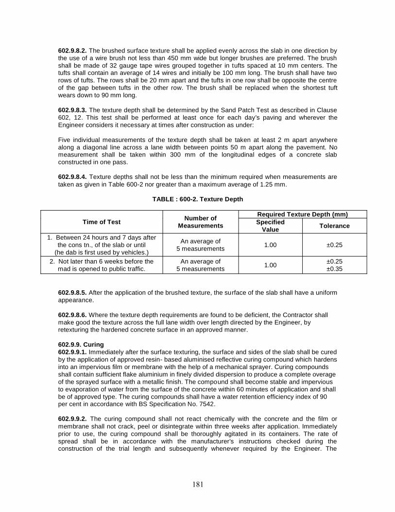
602.9.8.2. The brushed surface texture shall be applied evenly across the slab in one direction bythe use of a wire brush not less than 450 mm wide but longer brushes are preferred. The brushshall be made of 32 gauge tape wires grouped together in tufts spaced at 10 mm centers. Thetufts shall contain an average of 14 wires and initially be 100 mm long. The brush shall have tworows of tufts. The rows shall be 20 mm apart and the tufts in one row shall be opposite the centreof the gap between tufts in the other row. The brush shall be replaced when the shortest tuftwears down to 90 mm long.
602.9.8.3. The texture depth shall be determined by the Sand Patch Test as described in Clause602, 12. This test shall be performed at least once for each day’s paving and wherever theEngineer considers it necessary at times after construction as under:
Five individual measurements of the texture depth shall be taken at least 2 m apart anywherealong a diagonal line across a lane width between points 50 m apart along the pavement. Nomeasurement shall be taken within 300 mm of the longitudinal edges of a concrete slabconstructed in one pass.
602.9.8.4. Texture depths shall not be less than the minimum required when measurements aretaken as given in Table 600-2 nor greater than a maximum average of 1.25 mm.
TABLE : 600-2. Texture Depth
Time of Test Number ofMeasurements
Required Texture Depth (mm)Specified
Value Tolerance
1. Between 24 hours and 7 days afterthe cons tn., of the slab or until
(he dab is first used by vehicles.)
An average of5 measurements 1.00 ±0.25
2. Not later than 6 weeks before themad is opened to public traffic.
An average of5 measurements 1.00 ±0.25
±0.35
602.9.8.5. After the application of the brushed texture, the surface of the slab shall have a uniformappearance.
602.9.8.6. Where the texture depth requirements are found to be deficient, the Contractor shallmake good the texture across the full lane width over length directed by the Engineer, byretexturing the hardened concrete surface in an approved manner.
602.9.9. Curing602.9.9.1. Immediately after the surface texturing, the surface and sides of the slab shall be curedby the application of approved resin- based aluminised reflective curing compound which hardensinto an impervious film or membrane with the help of a mechanical sprayer. Curing compoundsshall contain sufficient flake aluminium in finely divided dispersion to produce a complete overageof the sprayed surface with a metallic finish. The compound shall become stable and imperviousto evaporation of water from the surface of the concrete within 60 minutes of application and shallbe of approved type. The curing compounds shall have a water retention efficiency index of 90per cent in accordance with BS Specification No. 7542.
602.9.9.2. The curing compound shall not react chemically with the concrete and the film ormembrane shall not crack, peel or disintegrate within three weeks after application. Immediatelyprior to use, the curing compound shall be thoroughly agitated in its containers. The rate ofspread shall be in accordance with the manufacturer’s instructions checked during theconstruction of the trial length and subsequently whenever required by the Engineer. The
mechanical sprayer shall incorporate an efficient mechanical device for con tinuous agitation andmixing of the compound during spraying.
602.9.9.3. In addition to spraying of curing compound, the fresh concrete surface shall beprotected for at least 3 hours by covering the finished concrete pavement with tents as describedin Clause 602.7.2, during adverse weather conditions as directed by the Engineer. After threehours, the pavement shall be covered by moist hessian and the same shall then be kept damp fora minimum period of 14 days after which time the hessian may be removed. The hessian shall bekept continuously moist. All damaged/torn hessian shall be removed and replaced by newhessian on a regular basis.
602.9.9.4. The Contractor shall be liable at his expense to replace any concrete damaged as aresult of incomplete curing or cracked on a line other than that of a joint.
602.10. Trial Length602.10.1. The trial length shall be constructed at least oil month in advance of the proposed startof concrete paving work. At least one month prior to the construction of the trial length, theContractor shall submit for the Engineer’s approval a detailed method statement givingdescription of the proposed materials, plant, equipment and construction methods. All the majorequipments like paving train, batching plant; tippers etc., proposed in the construction are to beapproved by the Engineer before their procurement. No trials of new materials, plant, equipmentor construction methods, or any development of them shall be permitted either during theconstruction of trial length or in any subsequent paving work, unless they form part of further,approved trials. These trial lengths shall be constructed away from the carriage way but with atleast a sub base layer below it.
602.10.2. The Contractor shall demonstrate the materials, plant, equipment and methods ofconstruction that are proposed for concrete paving, by first constructing a trial length of slab, atleast 60 m but not more than 300 m long for mechanised construction and at least 30 m long forhand guided methods. If the first trial is unsatisfactory, the Contractor shall have to demonstratehis capability to satisfactorily construct the pavement in subsequent trials.
602.10.3 The trial length shall be constructed in two parts over a period comprising at least part oftwo separate working days, with a minimum of 30 m constructed each day for mechanisedconstruction and a minimum of 15 m on each clay for hand guided construction. The trial lengthshall be constructed at a similar rate (speed, around lm/hr) to that which is proposed for the mainwork.
602.10.4. Transverse joints and longitudinal joints of each type that are proposed for dowel -jointed unreinforced concrete slabs in the main work shall be constructed and assessed in thetrial length. If in the trial length the construction of expansion joint and longitudinal joint is notdemonstrated, the first 2 expansion joints and at least the first 150 m of longitudinal constructionjoint for mechanised paving in the main work, shall be considered as the trial length for thesejoints.
602.10.5. The trial length shall comply with the Specification in all respects, with the followingadditions and exceptions;
602.10.5.1. Surface levels and regularity(i) In checking for compliance with Clause 903.5 the levels shall be taken at intervals at thelocations specified in this Clause along any line or lines parallel to the longitudinal centre line ofthe trial length.(ii) The maximum number of permitted irregularities of pavement surface shall comply with therequirements of Clause 902.4. Shorter trial lengths shall be assessed prorata based on values fora 300 m length.
602.10.5.2. Joints(iii) Alignment of dowel bars shall be inspected as described in Clause 602.10.7 in my twoconsecutive transverse joint. If the position or alignment of the dowel bars at one of these jointsdoes not comply with Clause 602.6.5. if that joint remains the only one that does not comply afterthe next 3 consecutive joints of the same typo have been inspected, then the method of placingdowels shall be deemed to be satisfactory. In order to check sufficient joints for dowel baralignment without Extending the trial length unduly, the Contractor may, by agreement with theEngineer, construct joints at more frequent joint intervals than the normal spacing required in theContract.
(iv) If there arc deficiencies in the first expansion joint that is constructed as a trial, the nextexpansion joint shall be a trial joint. Should this also be deficient, further trial expansion jointsshall be made as pan of the trial length which shall not form part of die permanent works, unlessagreed by the Engineer.
602.10.5.3. Density(v) Density shall be assessed as described in Clause 602.3.3. from at least 3 cores drilled fromeach part of the trial length.
602.10.5.4. Position of tie bars(vi) Compliance with Clause 602.6.6 for the position and alignment of tie bars shall be checked bydrilling additional cores from the slab unless they can be determined from cores taken for density.
602.10.6. Approval and acceptance602.10.6.1 Approval of the materials, plant, equipment and construction methods shall be givenwhen a trial length complies with the Specification. The Contractor shall not proceed with normalworking until the trial length has been approved and any earlier defective trial lengths have beenremoved, unless that can be remedied to the satisfaction of the Engineer. If the Engineer doesnot notify the Contractor of any deficiencies in any trial length within 10 days after the completionof that trial length, the Contractor may assume that the trial length, and the materials, plant,equipment and construction methods adopted are acceptable.
602.10.6.2. When approval has been given, the materials, plant, equipment and constructionmethods shall not thereafter be changed, except for normal adjustments and maintenance ofplant, without the approval of the Engineer. Any changes in materials, plant, equipment, andconstruction methods shall entitle the Engineer to require the Contractor to lay a further triallength as described in this Clause to demonstrate that the changes will not adversely affect thepermanent works.
602.10.6.3. Trial lengths which do not comply with the Specification, with the exception of areaswhich are deficient only in surface texture and which can be remedied in accordance with Clause602.9.8.6 shall be removed immediately upon notification of deficiencies by the Engineer and theContractor shall construct a further trial length.
602.10.7. Inspection of dowel bars602.10.7.1. Compliance with Clause 602.6,5, for the position and alignment of dowel bars atconstruction and expansion joints shall be checked by measurements relative to the side forms orguide wires.
602.10.7.2. When the slab has been constructed, the position and alignment of dowel bars andany filler board shall be measured after carefully exposing them in the plastic conc rete across diewhole width of the slab. When the joint is an expansion joint, the top of the filler board shall firstbe exposed sufficiently in the plastic concrete to permit measurement of any lateral or verticaldisplacement of the board. During the course of normal working, these measurements shall becarried out in the pavement section at the end of day’s work by extending slab length by 2 m.After sawing the transverse joint groove, the extended 2 m slab shall be removed carefully soon
after concrete has set to expose dowels over half the length. These dowels can be tested fo rtolerances,
602.10.7.3. If the position and alignment of the bars in a single joint in the slab is unsatisfactorythen the next two joints shall be inspected. If only one joint of the three is defective, the rate ofchecking shall be increased to one joint per day until the Engineer is satisfied that compliance isbeing achieved. In the event of non -compliance in two or more successive joints, the Contractorshall revert to the construction of fresh trial lengths and make any necessary alteration toconcrete mix, paving plant or methods until the dowel bar position and alignment are satisfactory.
602.10.7.4. After the dowel bars have been examined, the remainder of the concrete shall beremoved over a width of 500 mm on each side of the line of the joint and reinstated to thesatisfaction of the Engineer. The dowels shall be inserted on both sides of the 1m wide slab bydrilling holes and grouting with epoxy mortar. Plastic sheath as per Clause 602.6.5.5’shall beprovided on dowels on one of the joints. The joint groove shall be widened and sealed as perClause 602.11.
602.11. Preparation and Sealing of Joint Grooves602.11.1. GeneralAll transverse joints in surface slabs shall be sealed using sealants described in Clause 602.2.8.Joints shall not be sealed before 14 days after construction.
602.11.2. Preparation of joint grooves for sealing602.11.2.1. Joint grooves usually are not constructed to provide the minimum width specified inthe drawings when saw cut joints are adopted. They shall be widened subsequently by sawingbefore sealing. Depth/width gauges shall be used to control the dimension of the groove.
602.11.2.2. If rough arrises develop when grooves are made, they shall be ground to provide achamfer approximately 5 mm wide. If the groove is at an angle up to 10 degree from theperpendicular to the surface, the overhanging edge of the sealing groove shall be sawn or groundperpendicular. If spalling occurs or the angle of the former is greater than 10 degrees, the jointsealing groove shall be sawn wider and perpendicular to the surface to encompass the defects upto a maximum width, including any chamfer, of 35 mm for transverse joints and 20 mm forlongitudinal joints. If the spalling cannot be so eliminated then the arrises shall be repaired by anapproved thin bonded arris repair using cementitious materials.
602.11.2.3. All grooves shall be cleaned of any dirt or loose material by air blasting with filtered,oil- free compressed air. If need arises the Engineer may instruct cleaning by pressurised waterjets. Depending upon the requirement of the sealant manufacturer, the sides of the grooves mayhave to be sand blasted to increase the bondage between sealant and concrete.
602.11.2.4. The groove shall be cleaned and dried at the time of priming and sealing.
602.11.2.5. Before sealing the temporary seal provided for blocking the ingress of dirt, soil etc.,shall be removed. A highly compressible heat resistant paper-backed debonding strip as perdrawing shall be inserted in the groove to serve the purpose of breaking the bond betweensealant and the bottom of the groove and to plug the joint groove so that the sealant may not leakthrough the cracks. The width of debonding strip shall be more than the joint groove width so thatit is held tightly in the groove. In the case of longitudinal joints, heat resistant tapes may beinserted to block the leakage through bottom of the joint.
602.11.3. Sealing with sealants602.11.3.1. When sealants are applied, an appropriate primer shall also be used if recommendedby the manufacturer and it shall be applied in accordance with their recommendation. The sealantshall be applied within the minimum and maximum drying times of the primer recommended by
the manufacturer. Priming and sealing with applied sealants shall not be carried out when thenaturally occurring temperature in the joint groove to be sealed is below 7° C.
602.11.3.2. If hot applied sealant is used it shall be heated and applied from a thermostaticallycontrolled, indirectly heated preferably with oil jacketed meter and pourer having recirculationpump and extruder. For large road projects, sealant shall be applied with extruder having flexiblehose and nozzle. The sealant shall not be heated to a temperature higher than the saf e heatingtemperature and not for a period longer than the safe heating period, as specified by themanufacturer. The dispenser shall be cleaned our at the end of each day in accordance with themanufacturer’s recommendations and reheated material shall not be used.
602.11.3.3. Cold applied sealants with chemical formulation like polysulphide may be used.These shall be mixed and applied within the lime limit specified by the manufacturer. If primersare recommended they shall be applied neatly with an appropriate brush. The MovementAccommodation Factor (MAP) shall be more than 10 per cent.
602.11.3.4. The sealants applied at contraction phase of the slabs would result in bulging of thesealant over and above the slab. Therefore, the Contractor in consul tation with the Engineer,shall establish the right temperature and time for applying the sealant. Thermometer shall behung on a pole in the site for facilitating control during the sealing operation.
602.11.3.5. Sealant shall be applied, slightly to a lower level than the slab with a tolerance of 5 ±2 mm.
602.11.3.6. During sealing operation, it shall be seen that no air bubbles are introduced in thesealant either by v apours or by the sealing process.
602,11.4. Testing of applied sealants: Manufacturer’s certificate shall be produced by theContractor for establishing that the sealant is not more than six months old and stating that thesealant complies with the relevant standard as in Clause 602.2.8. The samples shall meet therequirement of AASHTO M 282 for hot applied sealant or BS 5212: (Part-2) for cold appliedsealant.
602.12. Measurement of Texture Depth - Sand Patch Method602.12.1. The following apparatus shall be used:(i) A cylindrical container of 25 ml internal capacity(ii) A flat wooden disc 64 mm diameter with a hard rubber disc. 1,5mm thick, slack to one face,the reverse face being provided with a handle(iii) Dry natural sand with a rounded particle shape passing a 300 micron IS sieve and retainedon a 150 micron IS sieve.
602.12.2. Method: The surface to be measured shall be dried, any extraneous mortar and loosematerial removed and the surface swept clean using a wire brush both at right angles and parallelto the carriageway. The cylindrical container shall be filled with the sand, tapping the base 3 timeson the surface to ensure compaction, and striking off the sand level with the top of the cylinder.The san d shall be poured into a heap on the surface to be treated. The sand shall be spreadover the surface, working The disc with its face kept flat in a circular motion so that the sand isspread into a circular patch with the surface depressions filled with sand to the level of peaks.
602.12.3. The diameter of the patch shall be measured to the nearest 5 mm. The texture depth ofconcrete surface shall be calculated from 31000/(D×D) mm where D is the diameter of the patchin mm,602.13. Opening to TrafficNo vehicular traffic shall be allowed to run on the finished surface of a concrete pavement withina period of 28 days of its construction and until the joints arc permanently sealed. The road maybe opened to regular traffic after completion of the curing period of 28 days and after scaling of
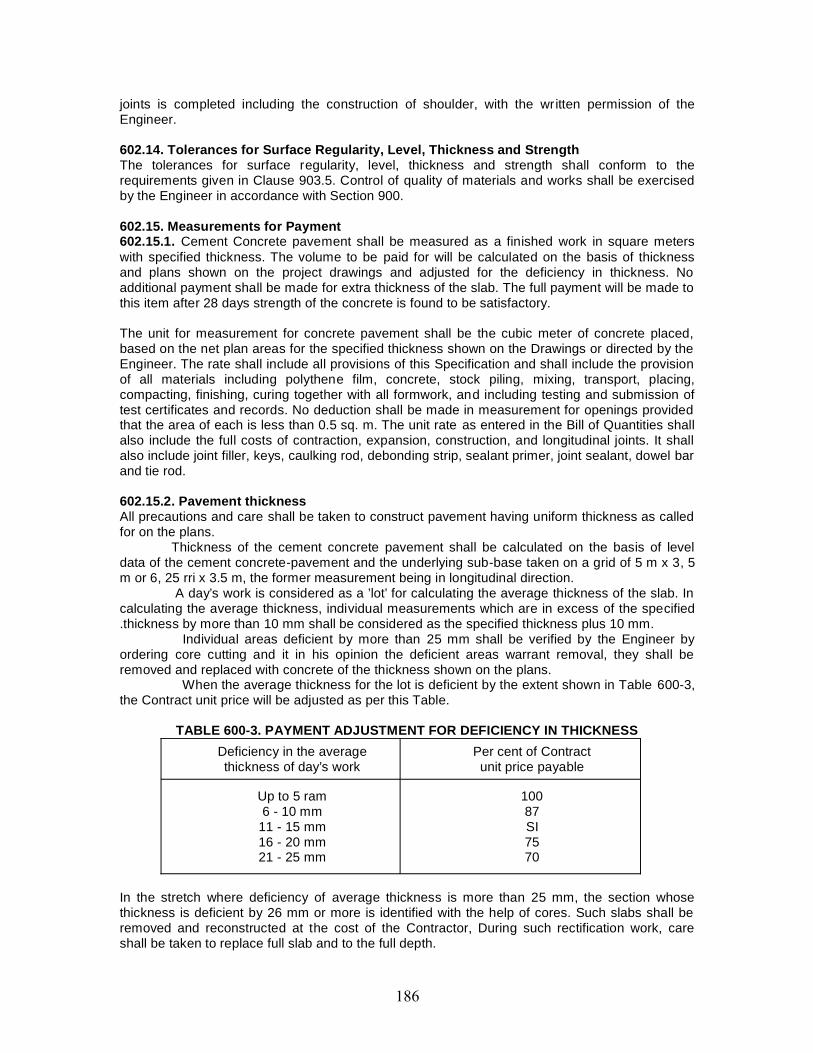
joints is completed including the construction of shoulder, with the written permission of theEngineer.
602.14. Tolerances for Surface Regularity, Level, Thickness and StrengthThe tolerances for surface regularity, level, thickness and strength shall conform to therequirements given in Clause 903.5. Control of quality of materials and works shall be exercisedby the Engineer in accordance with Section 900.
602.15. Measurements for Payment602.15.1. Cement Concrete pavement shall be measured as a finished work in square meterswith specified thickness. The volume to be paid for will be calculated on the basis of thicknessand plans shown on the project drawings and adjusted for the deficiency in thickness. Noadditional payment shall be made for extra thickness of the slab. The full payment will be made tothis item after 28 days strength of the concrete is found to be satisfactory.
The unit for measurement for concrete pavement shall be the cubic meter of concrete placed,based on the net plan areas for the specified thickness shown on the Drawings or directed by theEngineer. The rate shall include all provisions of this Specification and shall include the provisionof all materials including polythene film, concrete, stock piling, mixing, transport, placing,compacting, finishing, curing together with all formwork, and including testing and submission oftest certificates and records. No deduction shall be made in measurement for openings providedthat the area of each is less than 0.5 sq. m. The unit rate as entered in the Bill of Quantities shallalso include the full costs of contraction, expansion, construction, and longitudinal joints. It shallalso include joint filler, keys, caulking rod, debonding strip, sealant primer, joint sealant, dowel barand tie rod.
602.15.2. Pavement thicknessAll precautions and care shall be taken to construct pavement having uniform thickness as calledfor on the plans.
Thickness of the cement concrete pavement shall be calculated on the basis of leveldata of the cement concrete-pavement and the underlying sub-base taken on a grid of 5 m x 3, 5m or 6, 25 rri x 3.5 m, the former measurement being in longitudinal direction.
A day’s work is considered as a ’lot’ for calculating the average thickness of the slab. Incalculating the average thickness, individual measurements which are in excess of the specified.thickness by more than 10 mm shall be considered as the specified thickness plus 10 mm.
Individual areas deficient by more than 25 mm shall be verified by the Engineer byordering core cutting and it in his opinion the deficient areas warrant removal, they shall beremoved and replaced with concrete of the thickness shown on the plans.
When the average thickness for the lot is deficient by the extent shown in Table 600-3,the Contract unit price will be adjusted as per this Table.
TABLE 600-3. PAYMENT ADJUSTMENT FOR DEFICIENCY IN THICKNESSDeficiency in the averagethickness of day’s work
Per cent of Contractunit price payable
Up to 5 ram6 - 10 mm
11 - 15 mm16 - 20 mm21 - 25 mm
10087SI7570
In the stretch where deficiency of average thickness is more than 25 mm, the section whosethickness is deficient by 26 mm or more is identified with the help of cores. Such slabs shall beremoved and reconstructed at the cost of the Contractor, During such rectification work, careshall be taken to replace full slab and to the full depth.
602.16. RateThe Contract unit rate for the construction of the cement concrete shall be payment in full forcarrying out the operations required for the different items of the work as per these Specificationsincluding full compensation for all labour, tools, plant, equipments, testing and incidentals tocomplete the work as per Specifications, providing all materials to be incorpora ted in the workincluding all royalties, fees, storage, rents where necessary and all leads and lifts.
603. ROLLED CEMENT CONCRETE BASE
603.1. Scope603.1.1. The work shall consist of construction of rolled concrete base course for cementconcrete pavement in accordance with the requirements of these Specifications and in conformitywith the lines, grades and cross sections shown on the drawings or as directed by the Engineer.The work shall include furnishing of all plant and equipment, material and labour and performingall operations in connection with the work, as approved by the Engineer.
603.1.2. The design parameters of rolled cement concrete base course viz., width, thickness,grade of concrete, details of joints, if any, etc. shall be as stipulated in the contract drawings.
603.2. Materials603.2.1. Source of materials: The Contractor shall indicate to the Engineer the source of allmaterials to be used in the lean concrete work with relevant test data sufficiently in advance andthe approval of the Engineer for the same shall be obtained at least 50 days before the scheduledcommencement of the work. If the Contractor later proposes to obtain the materials from adifferent source, he shall notify the Engineer for his approval at least 60 days before suchmaterials are to be used.
603.2.2. Cement : Any of the following types of cement may be used with prior approval of theEngineer.
(i) Ordinary Portland Cement IS : 269. 8112 or 12269(ii) Portland Slag Cement IS : 455(iii) Portland Pozzolana Cement IS : 1489
If the sub grade is found to consist of soluble sulphates in a concentration more than 0.5 per cent,cement used shall be sulphate resistant and shall conform to IS: 12230, Cement to be used maypreferably be obtained in bulk form. It shall be stored in accordance with stipulations contained inClause 1014 and shall be subjected to acceptance test prior to its immediate use.
603.2.3. Aggregates :603.2.3.1. Aggregates for lean concrete shall be natural material complying with IS: 383, Theaggregates shall not be alkali reactive. The limits of deleterious materials shall not exceed therequirements set out in IS: 383. In case the Engineer considers that the aggregates are not freefrom dirt, the same may be washed and drained for at least 72 hours before batching as directedby the Engineer.603.2.3.2. Coarse aggregate: Coarse aggregates shall consist of clean, hard, strong, dense, non-porous and durable pieces of crushed stone or crushed gravel and shall be devoid of pieces ofdisintegrated stone, soft, flaky, elongated, very angular or splintery pieces. The maxi mum size ofthe coarse aggregate shall be 25 mm. The coarse aggregate shall comply with the Clause602.2.4.2.
603.2.3.3. Fine aggregate: The fine aggregate shall consist of clean natural sand or crushedstone sand or a combination of the two and shall conform to IS: 383, Fine aggregate shall be freefrom soft panicles, clay, shale, loam, cemented particles, mica, organic and other foreign matter.The fine aggregate shall comply with the Clause 602.2.4.3.
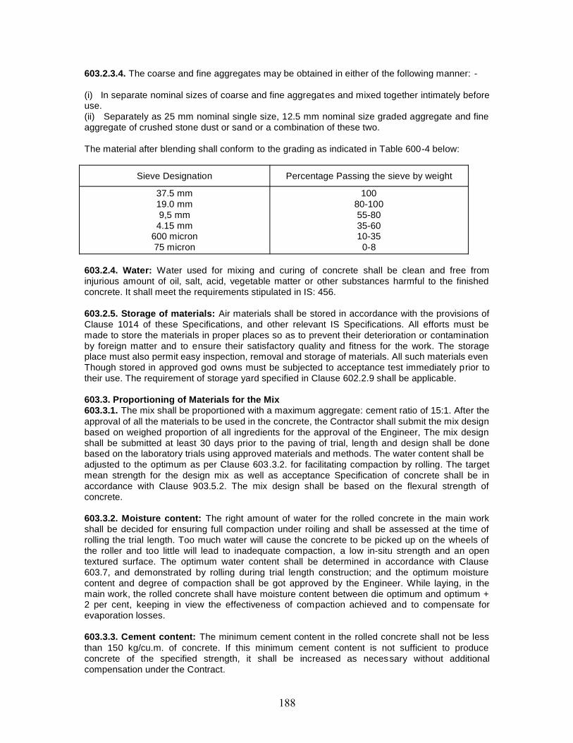
603.2.3.4. The coarse and fine aggregates may be obtained in either of the following manner: -
(i) In separate nominal sizes of coarse and fine aggregates and mixed together intimately beforeuse.(ii) Separately as 25 mm nominal single size, 12.5 mm nominal size graded aggregate and fineaggregate of crushed stone dust or sand or a combination of these two.
The material after blending shall conform to the grading as indicated in Table 600-4 below:
Sieve Designation Percentage Passing the sieve by weight
37.5 mm19.0 mm9,5 mm
4.15 mm600 micron75 micron
10080-10055-8035-6010-35
0-8
603.2.4. Water: Water used for mixing and curing of concrete shall be clean and free frominjurious amount of oil, salt, acid, vegetable matter or other substances harmful to the finishedconcrete. It shall meet the requirements stipulated in IS: 456.
603.2.5. Storage of materials: Air materials shall be stored in accordance with the provisions ofClause 1014 of these Specifications, and other relevant IS Specifications. All efforts must bemade to store the materials in proper places so as to prevent their deterioration or contaminationby foreign matter and to ensure their satisfactory quality and fitness for the work. The storageplace must also permit easy inspection, removal and storage of materials. All such materials evenThough stored in approved god owns must be subjected to acceptance test immediately prior totheir use. The requirement of storage yard specified in Clause 602.2.9 shall be applicable.
603.3. Proportioning of Materials for the Mix603.3.1. The mix shall be proportioned with a maximum aggregate: cement ratio of 15:1. After theapproval of all the materials to be used in the concrete, the Contractor shall submit the mix designbased on weighed proportion of all ingredients for the approval of the Engineer, The mix designshall be submitted at least 30 days prior to the paving of trial, length and design shall be donebased on the laboratory trials using approved materials and methods. The water content shall beadjusted to the optimum as per Clause 603.3.2. for facilitating compaction by rolling. The targetmean strength for the design mix as well as acceptance Specification of concrete shall be inaccordance with Clause 903.5.2. The mix design shall be based on the flexural strength ofconcrete.
603.3.2. Moisture content: The right amount of water for the rolled concrete in the main workshall be decided for ensuring full compaction under roiling and shall be assessed at the time ofrolling the trial length. Too much water will cause the concrete to be picked up on the wheels ofthe roller and too little will lead to inadequate compaction, a low in-situ strength and an opentextured surface. The optimum water content shall be determined in accordance with Clause603.7, and demonstrated by rolling during trial length construction; and the optimum moisturecontent and degree of compaction shall be got approved by the Engineer. While laying, in themain work, the rolled concrete shall have moisture content between die optimum and optimum +2 per cent, keeping in view the effectiveness of compaction achieved and to compensate forevaporation losses.
603.3.3. Cement content: The minimum cement content in the rolled concrete shall not be lessthan 150 kg/cu.m. of concrete. If this minimum cement content is not sufficient to produceconcrete of the specified strength, it shall be increased as necessary without additionalcompensation under the Contract.
603.3.4. Concrete strength: The flexural strength as specified shall be the governing criteria forapproval of the mix. While designing the mix in the laboratory, correlation between flexural andcompressive strengths of concrete shall be established on the basis of tests on samples for useat a later date to verify the in situ flexural strength of rolled concrete through testing of cores.
At least a batch of two beam and cube specimens, one each for 3 day and 7 daystrength testing shall be cast for every 100 cum or part thereof of concrete placed duringconstruction. On each day’s work not less than four beams and four cubes shall be made.
A ratio between the 3 and 7 day strengths shall be established for the mix to beused. This will help in assessing the fall in strength, if any in advance so that corrective action canbe taken for the future work.
603.4. Sub gradeThe sub grade shall conform to the grades and cross sections shown on the drawings and shallbe uniformly compacted to the design strength in accordance with these Specifications and theSpecification stipulated in the Contract. The rolled concrete base shall not be laid on a sub gradesoftened by rain after its final preparation; any surface trenches, soft spots etc., must be properlyback- filled and compacted to avoid any weak or soft spot. As far as possible, the constructiontraffic shall be avoided on the prepared sub grade. A day before placing of the sub-base, the subgrade surface shall be given a fine spray of water and rolled with one or two passes of a smoothwheeled roller after a lapse of 2-3 hours in order to stabilise the loose surface. If the Engineerfeels it necessary, another fine spray of water may be applied just before placing she basecourse. 603.5. Construction.
Clause 601, 5 shall apply.
603.6. Trial MixUsing the specified cement content and proportioned aggregates, the Contractor shall make trialmixes at water contents ranging from 5 per cent to 7 per cent by weight of dry materials at 0.5 percent intervals using an aggregate /cement ratio of not greater than 15.0. Optimum moisture anddensity shall be established by preparing cubes with varying moisture contents. The compactionof mould shall be done in three layers as explained in Clause 903.5.2.1, The optimum moisturecontent determined normally gives an indication about the moisture content which after minoradjustment may provide satisfactory mix which could be rolled.
After determining the moisture content from the above trial mix, a set of six beams and cubesshall be prepared for testing them on 3rd and 7th day. If the flexural strength achieved is lowerthan the desired strength, the above trial shall be repeated after increasing the cement contentand adjusting the mix appropriately.
During the construction of trial length as per Clause 603.7 minor modifications may have to becarried out to the moisture content of the mix. But such modified mix shall have to satisfy theflexural strength requirement. Flexural strength to be achieved ""Shall be the governing criteria forthe design of mix.
603.7. Trial LengthClause 601.7 shall apply.
603.8. TrafficNo heavy commercial vehicles like trucks and buses shall be permitted on the rolled concretebase after its construction. Light vehicles may be, however, allowed after 7 days of itsconstruction with prior approval of the Engineer,
603.9. Tolerances for Surface Regularity, Level, Thickness and StrengthThe tolerances for surface regularity, level, thickness and strength shall conform to therequirements given in Clause 903.5. Control of quality of materials and works shall be exercisedby the Engineer in accordance with Section 900.
603.10. Measurements for PaymentThe unit of measurement for concrete and rolled concrete pavement shall be the cubic meter ofconcrete placed, based on the net plan areas for the specified thickness shown on the drawingsas directed by the Engineer.
603.11. RateThe Contract unit rate payable for rolled cement concrete for base course shall be payment in fullfor carrying out the required operations including full compensation for all labour, materials andequipment, mixing, transport, placing, compacting, finishing, curing, testing and incidentals tocomplete the work as per Specifications, all royalties, fees, storage and rents where necessaryand all leads and lifts.


CONTENT
Clause No Description701 GEOSYNTHETICS IN ROAD AND BRIDGE WORKS
702 GEOTEXTILES IN SUB-SURFACE DRAINS
703 USE OF GEOSYNTHETICS IN COMPOSITE DRAINS
704 GEOTEXTILES FOR EROSION CONTROL
705 GEOGRID APPLICATIONS FOR REINFORCED SOIL SLOPE
PROTECTION
706 GEOSYNTHETICS FOR HIGHWAY PAVEMENTS
707 GEOSYNTHETICS OVER EXISTING BITUMENOUS SURFACE
708 PROTECTION WORKS WITH GEOSYNTHETICS
701 GEOSYNTHETICS IN ROAD AND BRIDGE WORKS
701.1 Scope
This specification covers the various applications of Geosynthetic materials in road and bridge worksincluding supplying and laying as per special provisions.
“Geosynthetic is a general classification for all synthetic materials used in geotechnical engineeringapplication. It includes geotextiles, geogrids, Geonets, geomembranes and geocomposites etc.
i) Geotextiles: They are indeed textiles in traditional sense, but consists of synthetic fibers.These fibers are generally non biogradable. The synthetic fibers are made into a flexible,porous fabric by standard weaving machinery or are matted together in a random, ornonwoven, manner. Some are also knit. Woven geotextiles are produced by weaving orinterlacing two or more sets of fibers usually at right angles. Non-woven geotextiles areproduced by mechanical bonding or needle punching of randomly oriented fibers. Insome cases, non-woven fibers may be bonded thermally or chemically. Geotextilesgenerally available have thickness varying from 0.25 mm to 7.5 mm and have a mass perunit area 150 to 2000 g/m2 referred as gsm. The major point is that they are porous towater flow across their manufactured plane or also within their plane, but to a widelyvarying degree. They are used in various geotechnical engineering applications forGeotextiles that have been developed; however, the fabric always perform at least fivediscrete functions i.e., separation, reinforcement, filtration, drainage and moisture barrier(when impregnated).
ii) Geogrids: These are primarily made of synthetic materials. Rather than being a woven,nonwoven, or knit textile; geogrids are formed into a very open, grid like configuration,i.e., they have large apertures. The geogrids are relatively high strength, high modulus,low-creep- sensitive polymers with apertures varying from 10 to 100 mm in size. Theopenings/holes in geogrids are either elongated ellipse, near squares with roundedcorners, squares or rectangles. Geogrids may be used for the purpose of separation butinvariable they are being used in some form of reinforcement.
iii) Geonets: Geonets constitute another specialized segment of geosynthetics. They areusually formed by a continuous of polymeric ribs at acute angle to one another. When theribs are opened, relatively large apertures are formed in a netlike configuration. Geonetsare like geogrids in configuration but they are used for the purpose of drainage. It is to benoted that geonets are always used with a geotextile, geomembrane or other material ontheir upper or lower surfaces. Clearly geonets are used for their drainage capability whilegeogrids are used for reinforcement.
iv) Geocomposite: A geocomposite consists of a combination of geotextile and geogrid; orgeogrid and geomembrane; or geotextile, geogrid and geomembrane or any of thesethree materials with another material in laminated or composite form. PrefabricatedVertical Drains or Band Drains, which are widely used for accelerating the consolidationof soft soils also come under the category of geocomposites.
v) Geomembranes : Geomembranes are also synthetic materials but they are imperviousand made of thin sheets of rubber or plastic materials used primarily for lining and coverof liquid-or solid-storage facilities.
701.2 Material Testing and AcceptanceUnless otherwise stated, the Geosynthetic materials shall conform to the requirements as under:
702.2.1 Geotextile: Geotextile shall be made of polyethylene or polypropylene or polyester orsimilar fibers, either woven or nonwoven or knitted in variety, through machine made process of heatbonding or needle punching or weaving techniques. These fabrics are required to pass water throughbut retain the soil particles, which require specific cross-plane permeability or permittivity and apparentopening size or equivalent opening size or 095. The above two requirements along with the requirementof strength and durability denote general characteristics of geotextiles to be used.
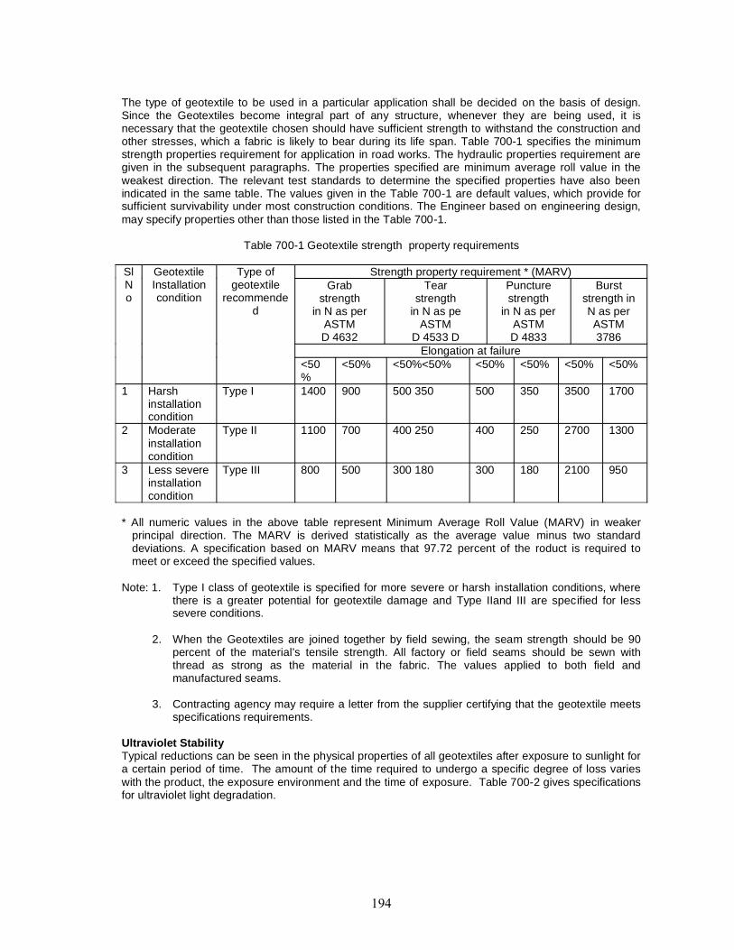
The type of geotextile to be used in a particular application shall be decided on the basis of design.Since the Geotextiles become integral part of any structure, whenever they are being used, it isnecessary that the geotextile chosen should have sufficient strength to withstand the construction andother stresses, which a fabric is likely to bear during its life span. Table 700-1 specifies the minimumstrength properties requirement for application in road works. The hydraulic properties requirement aregiven in the subsequent paragraphs. The properties specified are minimum average roll value in theweakest direction. The relevant test standards to determine the specified properties have also beenindicated in the same table. The values given in the Table 700-1 are default values, which provide forsufficient survivability under most construction conditions. The Engineer based on engineering design,may specify properties other than those listed in the Table 700-1.
Table 700-1 Geotextile strength property requirements
SlNo
GeotextileInstallationcondition
Type ofgeotextile
recommended
Strength property requirement * (MARV)Grab
strengthin N as per
ASTMD 4632
Tearstrength
in N as peASTM
D 4533 D
Puncturestrength
in N as perASTMD 4833
Burststrength inN as perASTM3786
Elongation at failure<50%
<50% <50%<50% <50% <50% <50% <50%
1 Harshinstallationcondition
Type I 1400 900 500 350 500 350 3500 1700
2 Moderateinstallationcondition
Type II 1100 700 400 250 400 250 2700 1300
3 Less severeinstallationcondition
Type III 800 500 300 180 300 180 2100 950
* All numeric values in the above table represent Minimum Average Roll Value (MARV) in weakerprincipal direction. The MARV is derived statistically as the average value minus two standarddeviations. A specification based on MARV means that 97.72 percent of the roduct is required tomeet or exceed the specified values.
Note: 1. Type I class of geotextile is specified for more severe or harsh installation conditions, wherethere is a greater potential for geotextile damage and Type IIand III are specified for lesssevere conditions.
2. When the Geotextiles are joined together by field sewing, the seam strength should be 90percent of the material’s tensile strength. All factory or field seams should be sewn withthread as strong as the material in the fabric. The values applied to both field andmanufactured seams.
3. Contracting agency may require a letter from the supplier certifying that the geotextile meetsspecifications requirements.
Ultraviolet StabilityTypical reductions can be seen in the physical properties of all geotextiles after exposure to sunlight fora certain period of time. The amount of the time required to undergo a specific degree of loss varieswith the product, the exposure environment and the time of exposure. Table 700-2 gives specificationsfor ultraviolet light degradation.
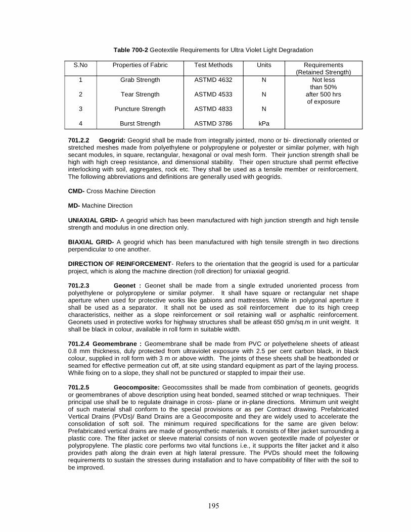
Table 700-2 Geotextile Requirements for Ultra Violet Light Degradation
S.No Properties of Fabric Test Methods Units Requirements(Retained Strength)
1
2
3
4
Grab Strength
Tear Strength
Puncture Strength
Burst Strength
ASTMD 4632
ASTMD 4533
ASTMD 4833
ASTMD 3786
N
N
N
kPa
Not lessthan 50%
after 500 hrsof exposure
701.2.2 Geogrid: Geogrid shall be made from integrally jointed, mono or bi- directionally oriented orstretched meshes made from polyethylene or polypropylene or polyester or similar polymer, with highsecant modules, in square, rectangular, hexagonal or oval mesh form. Their junction strength shall behigh with high creep resistance, and dimensional stability. Their open structure shall permit effectiveinterlocking with soil, aggregates, rock etc. They shall be used as a tensile member or reinforcement.The following abbreviations and definitions are generally used with geogrids.
CMD- Cross Machine Direction
MD- Machine Direction
UNIAXIAL GRID- A geogrid which has been manufactured with high junction strength and high tensilestrength and modulus in one direction only.
BIAXIAL GRID- A geogrid which has been manufactured with high tensile strength in two directionsperpendicular to one another.
DIRECTION OF REINFORCEMENT- Refers to the orientation that the geogrid is used for a particularproject, which is along the machine direction (roll direction) for uniaxial geogrid.
701.2.3 Geonet : Geonet shall be made from a single extruded unoriented process frompolyethylene or polypropylene or similar polymer. It shall have square or rectangular net shapeaperture when used for protective works like gabions and mattresses. While in polygonal aperture itshall be used as a separator. It shall not be used as soil reinforcement due to its high creepcharacteristics, neither as a slope reinforcement or soil retaining wall or asphaltic reinforcement.Geonets used in protective works for highway structures shall be atleast 650 gm/sq.m in unit weight. Itshall be black in colour, available in roll form in suitable width.
701.2.4 Geomembrane : Geomembrane shall be made from PVC or polyethelene sheets of atleast0.8 mm thickness, duly protected from ultraviolet exposure with 2.5 per cent carbon black, in blackcolour, supplied in roll form with 3 m or above width. The joints of these sheets shall be heatbonded orseamed for effective permeation cut off, at site using standard equipment as part of the laying process.While fixing on to a slope, they shall not be punctured or stappled to impair their use.
701.2.5 Geocomposite: Geocomssites shall be made from combination of geonets, geogridsor geomembranes of above description using heat bonded, seamed stitched or wrap techniques. Theirprincipal use shall be to regulate drainage in cross- plane or in-plane directions. Minimum unit weightof such material shall conform to the special provisions or as per Contract drawing. PrefabricatedVertical Drains (PVDs)/ Band Drains are a Geocomposite and they are widely used to accelerate theconsolidation of soft soil. The minimum required specifications for the same are given below:Prefabricated vertical drains are made of geosynthetic materials. It consists of filter jacket surrounding aplastic core. The filter jacket or sleeve material consists of non woven geotextile made of polyester orpolypropylene. The plastic core performs two vital functions i.e., it supports the filter jacket and it alsoprovides path along the drain even at high lateral pressure. The PVDs should meet the followingrequirements to sustain the stresses during installation and to have compatibility of filter with the soil tobe improved.
Physical requirements:
Weight e” 90 gm/sq. m, Width e” 90 mm and Thickness e” 5mm
Filter criterion requirement: The two key parameters that indicate the quality of filter are AOS(Apparent opening size) and cross plane permeability of filter. It is recommended that the followingcriteria be adopted for selection of PVDs.
O95 d” (2-3) D85 and O50 d” ( 10-12) D50
Where O95 is AOS of filter, O50 is size that is larger than 50% of fabric pores, D85 and D50refer to sizes of 85 percent and 50 percent of passing of soil particles by weight.
Permeability Requirement: The permeability of filter is normally required to be at least one order ofmagnitude higher than that of soil. The PVDs are generally used to accelerate the consolidation of verysoft saturated soils such as marine clay. The permeability of soils found in India generally havepermeability of the order of 10-7 to 10-10 m/s. Considering the clogging effect, a much higherpermeability is required. To avoid clogging it is recommended that the permeability of PVDs should atleast be of the order of 10-4 m/s.
701.2.6 Testing, handling, certification and acceptance: Geosynthetics shall be tested inaccordance with tests prescribed by ASTM/ BIS for respective applications. In absence of ASTM/BISCodes, tests prescribed either by British Standards or International Standards Organization, shall beconducted. The supplier of the geotextile should provide to the Engineer, a certificate stating the nameof the manufacturer, product name, style number, roll number, chemical composition of the filaments oryarns and other pertinent information regarding property values of individual roll to fully describe thegeosynthetics.
The manufacturer is responsible for establishing and maintaining a quality control programme to assurecompliance with the requirements of the specifications. Documentation describing the quality controlprogramme shall be made available upon request. The manufacturer certificate shall state that thefurnished geotextile meets MARV requirements of the specifications as evaluated under theManufacturer’s quality control programme and are in conformance as per ASTM D 4759. The certificateshall be attested by a person having legal authority to bind the manufacturer.
702.2.6.1 Handling and Storage of GeosyntheticsGeosynthetics must be handled and stored properly to ensure that the specified physical properties areretained to serve project needs. Geosynthetics rolls shall be furnished with suitable wrapping forprotection against moisture, and extended ultraviolet exposure to ultraviolet exposure prior toplacement. Each roll should be labeled or tagged to provide product identification sufficient for inventoryand quality control purposes. Rolls should be stored in manner which protects them for elements. Ifstored outdoors, they shall be elevated and protected with water proof cover.The damages caused onthis account can significantly educe the geosynthetics ability to perform its intended function in someapplications.
The objective of geosynthetics handling and storage is to safely transport and store the geotextile rollsat the project site without damaging the geosynthetics or unduly exposing it to sun light (ultravioletlight), moisture or other contamination. The following are some of the general recommendations to befollowed while working with geosynthetics at site.
Site HandlingRolls of geosynthetics should always be lifted off the ground surface prior to moving. Dragging thegeosynthetics and operating equipment on the geosynthetics, which results in physical damage, shallbe avoided at all times.
Site StorageThe geosynthetics rolls shall be adequately protected from ultraviolet light exposure during storage onsite. A protective wrapping shall be kept on rolls until the geosynthetics are installed. If stored outside,the geotextile should be elevated from the ground surface and adequately covered to protect them fromsite construction damage, precipitation, ultraviolet radiation including sun light, chemicals that are
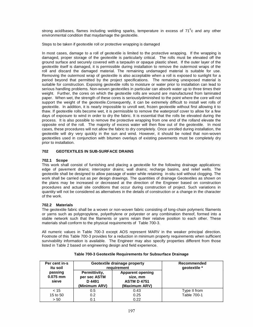
strong acid/bases, flames including welding sparks, temperature in excess of 710c and any otherenvironmental condition that maydamage the geotextile.
Steps to be taken if geotextile roll or protective wrapping is damaged
In most cases, damage to a roll of geotextile is limited to the protective wrapping. If the wrapping isdamaged, proper storage of the geotextile is particularly critical. The rolls must be elevated off theground surface and securely covered with a tarpaulin or opaque plastic sheet. If the outer layer of thegeotextile itself is damaged, it is permissible during installation to remove the outermost wraps of theroll and discard the damaged material. The remaining undamaged material is suitable for use.Removing the outermost wrap of geotextile is also acceptable when a roll is exposed to sunlight for aperiod beyond that permitted by the project specifications. The remaining unexposed material issuitable for construction. Exposing geotextile rolls to moisture or water prior to installation can lead toserious handling problems. Non-woven geotextiles in particular can absorb water up to three times theirweight. Further, the cores on which the geotextile rolls are wound are manufactured from laminatedpaper. When wet, the strength of these cores is seriouslydiminished to the point where the core will notsupport the weight of the geotextile.Consequently, it can be extremely difficult to install wet rolls ofgeotextile. In addition, it is nearly impossible to unroll wet, frozen geotextile without first allowing it tothaw. If geotextile rolls become wet, it is permissible to remove the waterproof cover to allow for a fewdays of exposure to wind in order to dry the fabric. It is essential that the rolls be elevated during theprocess. It is also possible to remove the protective wrapping from one end of the rolland elevate theopposite end of the roll. The majority of excess water will then flow out of the geotextile. In mostcases, these procedures will not allow the fabric to dry completely. Once unrolled during installation, thegeotextile will dry very quickly in the sun and wind. However, it should be noted that non-wovengeotextiles used in conjunction with bitumen overlays of existing pavements must be completely dryprior to installation.
702 GEOTEXTILES IN SUB-SURFACE DRAINS
702.1 ScopeThis work shall consist of furnishing and placing a geotextile for the following drainage applications:edge of pavement drains; interceptor drains; wall drains; recharge basins, and relief wells. Thegeotextile shall be designed to allow passage of water while retaining in-situ soil without clogging. Thework shall be carried out as per design drawings. The quantities of drainage Geotextiles as shown onthe plans may be increased or decreased at the direction of the Engineer based on constructionprocedures and actual site conditions that occur during construction of project. Such variations inquantity will not be considered as alternatives in the details of construction or a change in the characterof the work.
702.2 MaterialsThe geotextile fabric shall be a woven or non-woven fabric consisting of long-chain polymeric filamentsor yarns such as polypropylene, polyethylene or polyester or any combination thereof, formed into astable network such that the filaments or yarns retain their relative position to each other. Thesematerials shall conform to the physical requirements of Table 700-3.
All numeric values in Table 700-3 except AOS represent MARV in the weaker principal direction.Footnote of this Table 700-3 provides for a reduction in minimum property requirements when sufficientsurvivability information is available. The Engineer may also specify properties different from thoselisted in Table 2 based on engineering design and field experience.
Table 700-3 Geotextile Requirements for Subsurface Drainage
Per cent in-situ soil
passing0.075 mm
sieve
Geotextile drainage propertyrequirement
Recommendedgeotextile *
Permittivity,per sec ASTM
D 4491(Minimum ARV)
Apparent openingsize, mm
ASTM D 4751(Maximum ARV)
< 1515 to 50
> 50
0.50.20.1
0.430.250.22
Type II fromTable 700-1
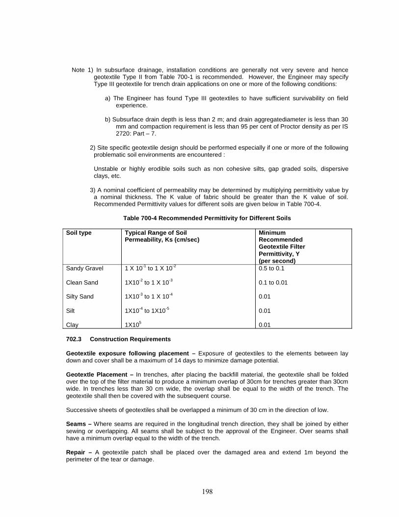
Note 1) In subsurface drainage, installation conditions are generally not very severe and hencegeotextile Type II from Table 700-1 is recommended. However, the Engineer may specifyType III geotextile for trench drain applications on one or more of the following conditions:
a) The Engineer has found Type III geotextiles to have sufficient survivability on fieldexperience.
b) Subsurface drain depth is less than 2 m; and drain aggregatediameter is less than 30mm and compaction requirement is less than 95 per cent of Proctor density as per IS2720: Part – 7.
2) Site specific geotextile design should be performed especially if one or more of the followingproblematic soil environments are encountered :
Unstable or highly erodible soils such as non cohesive silts, gap graded soils, dispersiveclays, etc.
3) A nominal coefficient of permeability may be determined by multiplying permittivity value bya nominal thickness. The K value of fabric should be greater than the K value of soil.Recommended Permittivity values for different soils are given below in Table 700-4.
Table 700-4 Recommended Permittivity for Different Soils
Soil type Typical Range of SoilPermeability, Ks (cm/sec)
MinimumRecommendedGeotextile FilterPermittivity, Y(per second)
Sandy Gravel
Clean Sand
Silty Sand
Silt
Clay
1 X 10⁻¹ to 1 X 10⁻²
1X10⁻² to 1 X 10⁻³
1X10⁻³ to 1 X 10⁻⁴
1X10⁻⁴ to 1X10⁻⁵
1X10⁵
0.5 to 0.1
0.1 to 0.01
0.01
0.01
0.01
702.3 Construction Requirements
Geotextile exposure following placement – Exposure of geotextiles to the elements between laydown and cover shall be a maximum of 14 days to minimize damage potential.
Geotextle Placement – In trenches, after placing the backfill material, the geotextile shall be foldedover the top of the filter material to produce a minimum overlap of 30cm for trenches greater than 30cmwide. In trenches less than 30 cm wide, the overlap shall be equal to the width of the trench. Thegeotextile shall then be covered with the subsequent course.
Successive sheets of geotextiles shall be overlapped a minimum of 30 cm in the direction of low.
Seams – Where seams are required in the longitudinal trench direction, they shall be joined by eithersewing or overlapping. All seams shall be subject to the approval of the Engineer. Over seams shallhave a minimum overlap equal to the width of the trench.
Repair – A geotextile patch shall be placed over the damaged area and extend 1m beyond theperimeter of the tear or damage.
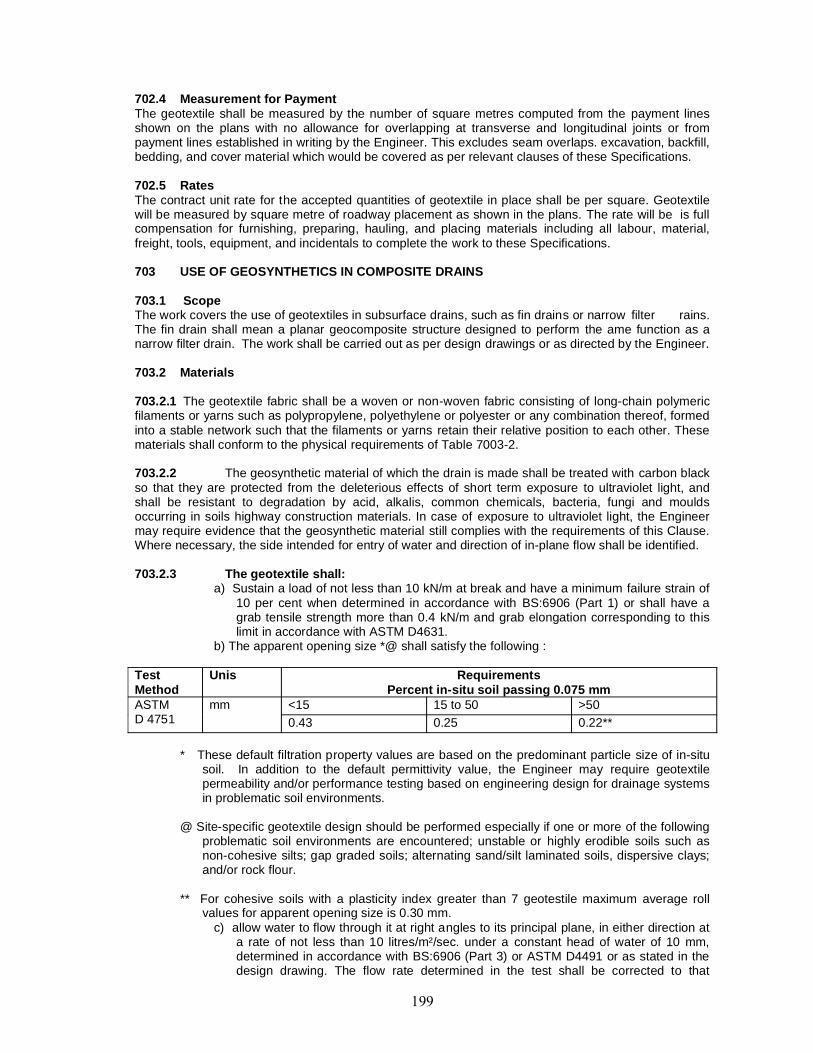
702.4 Measurement for PaymentThe geotextile shall be measured by the number of square metres computed from the payment linesshown on the plans with no allowance for overlapping at transverse and longitudinal joints or frompayment lines established in writing by the Engineer. This excludes seam overlaps. excavation, backfill,bedding, and cover material which would be covered as per relevant clauses of these Specifications.
702.5 RatesThe contract unit rate for the accepted quantities of geotextile in place shall be per square. Geotextilewill be measured by square metre of roadway placement as shown in the plans. The rate will be is fullcompensation for furnishing, preparing, hauling, and placing materials including all labour, material,freight, tools, equipment, and incidentals to complete the work to these Specifications.
703 USE OF GEOSYNTHETICS IN COMPOSITE DRAINS
703.1 ScopeThe work covers the use of geotextiles in subsurface drains, such as fin drains or narrow filter rains.The fin drain shall mean a planar geocomposite structure designed to perform the ame function as anarrow filter drain. The work shall be carried out as per design drawings or as directed by the Engineer.
703.2 Materials
703.2.1 The geotextile fabric shall be a woven or non-woven fabric consisting of long-chain polymericfilaments or yarns such as polypropylene, polyethylene or polyester or any combination thereof, formedinto a stable network such that the filaments or yarns retain their relative position to each other. Thesematerials shall conform to the physical requirements of Table 7003-2.
703.2.2 The geosynthetic material of which the drain is made shall be treated with carbon blackso that they are protected from the deleterious effects of short term exposure to ultraviolet light, andshall be resistant to degradation by acid, alkalis, common chemicals, bacteria, fungi and mouldsoccurring in soils highway construction materials. In case of exposure to ultraviolet light, the Engineermay require evidence that the geosynthetic material still complies with the requirements of this Clause.Where necessary, the side intended for entry of water and direction of in-plane flow shall be identified.
703.2.3 The geotextile shall:a) Sustain a load of not less than 10 kN/m at break and have a minimum failure strain of
10 per cent when determined in accordance with BS:6906 (Part 1) or shall have agrab tensile strength more than 0.4 kN/m and grab elongation corresponding to thislimit in accordance with ASTM D4631.
b) The apparent opening size *@ shall satisfy the following :
TestMethod
Unis RequirementsPercent in-situ soil passing 0.075 mm
ASTMD 4751
mm <15 15 to 50 >500.43 0.25 0.22**
* These default filtration property values are based on the predominant particle size of in-situsoil. In addition to the default permittivity value, the Engineer may require geotextilepermeability and/or performance testing based on engineering design for drainage systemsin problematic soil environments.
@ Site-specific geotextile design should be performed especially if one or more of the followingproblematic soil environments are encountered; unstable or highly erodible soils such asnon-cohesive silts; gap graded soils; alternating sand/silt laminated soils, dispersive clays;and/or rock flour.
** For cohesive soils with a plasticity index greater than 7 geotestile maximum average rollvalues for apparent opening size is 0.30 mm.
c) allow water to flow through it at right angles to its principal plane, in either direction ata rate of not less than 10 litres/m²/sec. under a constant head of water of 10 mm,determined in accordance with BS:6906 (Part 3) or ASTM D4491 or as stated in thedesign drawing. The flow rate determined in the test shall be corrected to that
applicable to a temperature of 15°C using published data on variation iin viscosity ofwater with temperature.
d) have a minimum puncture resistance of 200 N when determined in accordance withBS:6906 (Part 4) or ASTM D 4833.
e) have a minimum tear resistance of 150 N when determined in accordance with ASTMStandard D 4533.
703.2.4 The composite drain shall have flow rate through each face of the drain of more than75 per cent of the value specified in sub-Clause 702.2.3.(c), determined by direct measurement of thecomposite drain using BS:6906 (Part 3). The composite drain shall have values of long-term in-planeflow rates as stated in the design
703.3 Installation
The installation of fin drains shall be as per the design drawings. Where fin drains are assembled onsite, the assembly area shall be clean and dry and free of any wind-borne pollutants. No geotextile orcore material shall be exposed to daylight (or any source of ultraviolet radiation) for a period exceedinga cumulative total of 50 hours. Where fin drains are laid in trench, the bottom of the trench shall be freeof irregularities and shall be brought to the required level. Rock and other hard protrusions shall beremoved and any excess cut in the trench bottom filled and compacted back to the required grade withsuitable excavated or imported material as directed by the Engineer. Fin drains shall be capable ofbeing jointed longitudinal or laterally into pipe systems or chambers for inflow and outflow purposes.Joints parallel to the direction of flow and any exposed edge shall be protected from the ingress of soilby a geotextile wrapping with a minimum overlap of 150 mm or other measures as agreed by theEngineer.
703.4 Narrow filter drains consisting of a porous or perforated pipe and in a narrow trench surroundedby a layer of geotextile filter shall have the same properties of geotextile as specified in Clause 703.2.The spicing of lengths of geotextile and minimum overlap shall be as per the design drawing or asapproved by the Engineer. Such drains shall be installed as per the design drawing to Clauses 703.3and 309.3.5. 703.5
Measurement for PaymentMeasurement for fin drain/narrow filter drains shall be per running metre length of the drain.
703.6 RateThe Contract unit rates for subsurface drains shall be payment in full for all items such as excavation,dressing the sides and bottom, providing geotextile composites, laying and jointing pipes etc. includingfull compensation for all materials, labour, tools equipment incidental to complete the work as shown ondrawings with all leads and lifts including removal of unsuitable material. Provision of inlets, outletpipes, bedding, etc., wherever required shall be incidental to construction of drain.
704 GEOTEXTILES FOR EROSION CONTROL
704.1 ScopeThis work shall consist of furnishing and placing a geotextile for erosion control application’s such ascut and fill slope protection, protection of various small drainage structures and, ditches, waveprotection for causeways and shore line roadway embankments, and scour protection for structures(bridge piers and abutments). The geotextile shall be designed to allow passage of water whileretaining in situ soil without clogging. The quantities of erosion control geotextiles as shown on theplans maybe increased or decreased at the direction of the Engineer based on construction procedureand actual site conditions that occur during construction of the project. Such variations in quantity willnot be considered as alterations in the details of construction or a change in the character of the wok.
704.2 Materials704.2.1 Fibers used in the manufacture of geotextile, and the threads used in joining geotextiles bysewing, shall consist of long-chain synthetic polymers, composed of at least 85% by weight polyolefins,polyesters, or polyamides. They shall be formed into a network such that the filaments or yarns retain
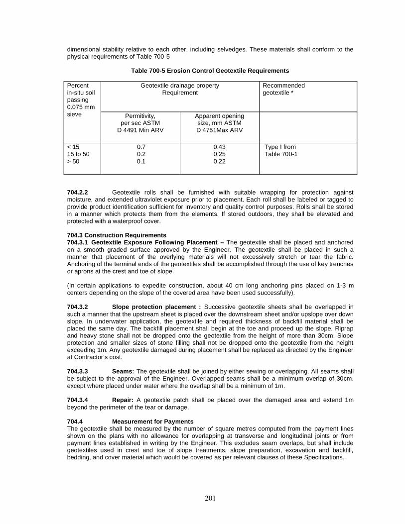
dimensional stability relative to each other, including selvedges. These materials shall conform to thephysical requirements of Table 700-5
Table 700-5 Erosion Control Geotextile Requirements
Percentin-situ soilpassing0.075 mmsieve
Geotextile drainage propertyRequirement
Recommendedgeotextile *
Permitivity,per sec ASTM
D 4491 Min ARV
Apparent openingsize, mm ASTMD 4751Max ARV
< 1515 to 50> 50
0.70.20.1
0.430.250.22
Type I fromTable 700-1
704.2.2 Geotextile rolls shall be furnished with suitable wrapping for protection againstmoisture, and extended ultraviolet exposure prior to placement. Each roll shall be labeled or tagged toprovide product identification sufficient for inventory and quality control purposes. Rolls shall be storedin a manner which protects them from the elements. If stored outdoors, they shall be elevated andprotected with a waterproof cover.
704.3 Construction Requirements704.3.1 Geotextile Exposure Following Placement – The geotextile shall be placed and anchoredon a smooth graded surface approved by the Engineer. The geotextile shall be placed in such amanner that placement of the overlying materials will not excessively stretch or tear the fabric.Anchoring of the terminal ends of the geotextiles shall be accomplished through the use of key trenchesor aprons at the crest and toe of slope.
(In certain applications to expedite construction, about 40 cm long anchoring pins placed on 1-3 mcenters depending on the slope of the covered area have been used successfully).
704.3.2 Slope protection placement : Successive geotextile sheets shall be overlapped insuch a manner that the upstream sheet is placed over the downstream sheet and/or upslope over downslope. In underwater application, the geotextile and required thickness of backfill material shall beplaced the same day. The backfill placement shall begin at the toe and proceed up the slope. Riprapand heavy stone shall not be dropped onto the geotextile from the height of more than 30cm. Slopeprotection and smaller sizes of stone filling shall not be dropped onto the geotextile from the heightexceeding 1m. Any geotextile damaged during placement shall be replaced as directed by the Engineerat Contractor’s cost.
704.3.3 Seams: The geotextile shall be joined by either sewing or overlapping. All seams shallbe subject to the approval of the Engineer. Overlapped seams shall be a minimum overlap of 30cm.except where placed under water where the overlap shall be a minimum of 1m.
704.3.4 Repair: A geotextile patch shall be placed over the damaged area and extend 1mbeyond the perimeter of the tear or damage.
704.4 Measurement for PaymentsThe geotextile shall be measured by the number of square metres computed from the payment linesshown on the plans with no allowance for overlapping at transverse and longitudinal joints or frompayment lines established in writing by the Engineer. This excludes seam overlaps, but shall includegeotextiles used in crest and toe of slope treatments, slope preparation, excavation and backfill,bedding, and cover material which would be covered as per relevant clauses of these Specifications.
704.5 RatesThe contract unit rate for the accepted quantities of geotextile in place shall be per square. The rate isfull compensation for furnishing, preparing, hauling, and placing materials including all labour, material,freight, tools, equipment, and incidentals to complete the work to these Specifications.
705 GEOGRID APPLICATIONS FOR REINFORCED SOIL SLOPE PROTECTION
705.1 Description: This work shall consist of constructing a reinforced soil slope inaccordance with the contract documents and as directed by the Engineer. The Contractor shall provideall labour, equipment, and materials for and incidental to site preparation, furnishing, installing, andbackfilling geogrid reinforcement as indicated.
705.2 MaterialGeogrid reinforcement: The geogrid reinforcement for primary slope stabilization shall be uniaxiallyoriented grid structure. The geogrid reinforcement for secondary slope stabilization shall be a biaxiallyoriented grid structure. The manufacturer shall furnish the Engineer with test reports certifying that theproduct meets the requirements of these Specifications. Un-iaxail and bi-axaial geogrid shall be regulargrid structure. The geogrid shall have high resistance to deformation under sustained long-term designload while in service and shall be resistant to ultraviolet degradation, damage under normalconstruction practices and all forms of biological or chemical degradation normally encountered in thematerial being reinforced. The long term allowable tensile strength shall have the minimum value of156.6 kN/m. The minimum pull-out resistance factor shall be 0.42 as determined by ASTM D 6706.
Backfill: The contractor shall provide select granular backfill material as per contract.
Facing: The contractor shall provide stone fill and geotextile as facing for the reinforced soil slope tothe lines and grades shown on the plans.
705.3 InstallationAll areas immediately beneath the installation area for the geogrid shall be properly prepared asdetailed on the plans and as per these Specifications or as directed by the Engineer.The geogrid shall be installed in accordance with the manufacturere’s recommendation. The geogridshall be placed within the layers of the compacted soil as shown on the plans or as directed by theEngineer. If the contractor is unable to complete a required length with a single continuous length ofgeogrid a joint may be made with the approval of the Engineer. After the specified layer has beenplaced in its entirety and compacted, the next geogrid layer shall be installed in its entirety. The processshall be repeated for such subsequent layer of geogrid and soil. Geogrid reinforcement shall be placedto lay flat and pulled tight prior to backfilling . After a layer of geogrid has been placed , suitable means,such as pins or small piles of soil shall be used to hold geogrid in position until the subsequent soil layercan be placed. Under no circumstances shall a track type vehicle be allowed on the geogrid before atleast 150mm of soil has been placed.
Backfill placement: Backfill shall be compacted as specified by project specifications or at least 95percent of the maximum density determined in accordance with IS:2726 (Part-8), whichever is greater.Backfill within 900 mm of slope face shall typically be compacted with hand equipment. Fill shall beplaced in 200 mm maximum lift thickness.
705.4 Measurement and basis of payment : The quantity of special provision to bemeasured for payment will the number of square meters of geogrid installed in the complete andaccepted work.
705.5 RatesThe Contract unit rate will be full compensation for furnishing and installing the specified materials inaccordance with the contract documents including on-site supplier representation, site preparation,geosynthetics reinforcement and backfill and for furnishing all labor, tools equipment and incidentalsnecessary to complete the work to these Specification.
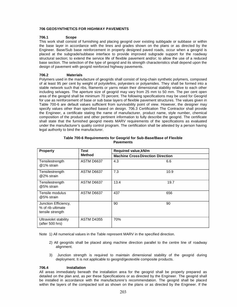
706 GEOSYNTHETICS FOR HIGHWAY PAVEMENTS
706.1 ScopeThis work shall consist of furnishing and placing geogrid over existing subbgade or subbase or withinthe base layer in accordance with the lines and grades shown on the plans or as directed by theEngineer. Base/Sub base reinforcement in properly designed paved roads, occur when a geogrid isplaced at the subgrade/subbase interface to provide improved subgrade support for the roadwaystructural section; to extend the service life of flexible pavement and/or; to allow the use of a reducedbase section. The selection of the type of geogrid and its strength characteristics shall depend upon thedesign of pavement with geogrid reinforced highway pavements.
706.2 MaterialsPolymers used in the manufacture of geogrids shall consist of long-chain synthetic polymers, composedof at least 95 per cent by weight of polyolefins, polyesters or polyamides. They shall be formed into astable network such that ribs, filaments or yarns retain their dimensional stability relative to each otherincluding selvages. The aperture size of geogrid may vary from 25 mm to 50 mm. The per cent openarea of the geogrid shall be minimum 70 percent. The following specifications may be used for Geogridfor use as reinforcement of base or sub base layers of flexible pavement structures. The values given inTable 700-6 are default values sufficient from survivability point of view. However, the designer mayspecify values other than specified based on design. 706.3 Certification The Contractor shall providethe Engineer, a certificate stating the name of manufacturer, product name, style number, chemicalcomposition of the product and other pertinent information to fully describe the geogrid. The certificateshall state that the furnished geogrid meets MARV requirements of the specifications as evaluatedunder the manufacturer’s quality control program. The certification shall be attested by a person havinglegal authority to bind the manufacturer.
Table 700-6 Requirements for Geogrid for Sub-Base/Base of FlexiblePavements
Property TestMethod
Required value,kN/mMachine CrossDirection Direction
Tensilestrength@1% strain
ASTM D6637 4.3 6.6
Tensilestrength@2% strain
ASTM D6637 7.3 10.9
Tensilestrength@5% strain
ASTM D6637 13.4 19.7
Tensile modulus@5% strain
ASTM D6637 437 656
Junction Efficiency,% of rib ultimatetensile strength
90 90
Ultraviolet stability(after 500 hrs)
ASTM D4355 70%
Note 1) All numerical values in the Table represent MARV in the specified direction.
2) All geogrids shall be placed along machine direction parallel to the centre line of roadwayalignment.
3) Junction strength is required to maintain dimensional stability of the geogrid duringdeployment. It is not applicable to geogrid/geotextile composite products.
706.4 InstallationAll areas immediately beneath the installation area for the geogrid shall be properly prepared asdetailed on the plan and, as per these Specifications or as directed by the Engineer. The geogrid shallbe installed in accordance with the manufacturere’s recommendation. The geogrid shall be placedwithin the layers of the compacted soil as shown on the plans or as directed by the Engineer. If the
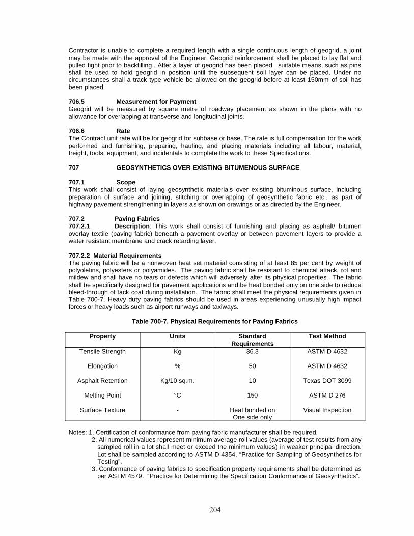
Contractor is unable to complete a required length with a single continuous length of geogrid, a jointmay be made with the approval of the Engineer. Geogrid reinforcement shall be placed to lay flat andpulled tight prior to backfilling . After a layer of geogrid has been placed , suitable means, such as pinsshall be used to hold geogrid in position until the subsequent soil layer can be placed. Under nocircumstances shall a track type vehicle be allowed on the geogrid before at least 150mm of soil hasbeen placed.
706.5 Measurement for PaymentGeogrid will be measured by square metre of roadway placement as shown in the plans with noallowance for overlapping at transverse and longitudinal joints.
706.6 RateThe Contract unit rate will be for geogrid for subbase or base. The rate is full compensation for the workperformed and furnishing, preparing, hauling, and placing materials including all labour, material,freight, tools, equipment, and incidentals to complete the work to these Specifications.
707 GEOSYNTHETICS OVER EXISTING BITUMENOUS SURFACE
707.1 ScopeThis work shall consist of laying geosynthetic materials over existing bituminous surface, includingpreparation of surface and joining, stitching or overlapping of geosynthetic fabric etc., as part ofhighway pavement strengthening in layers as shown on drawings or as directed by the Engineer.
707.2 Paving Fabrics707.2.1 Description: This work shall consist of furnishing and placing as asphalt/ bitumenoverlay textile (paving fabric) beneath a pavement overlay or between pavement layers to provide awater resistant membrane and crack retarding layer.
707.2.2 Material RequirementsThe paving fabric will be a nonwoven heat set material consisting of at least 85 per cent by weight ofpolyolefins, polyesters or polyamides. The paving fabric shall be resistant to chemical attack, rot andmildew and shall have no tears or defects which will adversely alter its physical properties. The fabricshall be specifically designed for pavement applications and be heat bonded only on one side to reducebleed-through of tack coat during installation. The fabric shall meet the physical requirements given inTable 700-7. Heavy duty paving fabrics should be used in areas experiencing unusually high impactforces or heavy loads such as airport runways and taxiways.
Table 700-7. Physical Requirements for Paving Fabrics
Property Units StandardRequirements
Test Method
Tensile Strength
Elongation
Asphalt Retention
Melting Point
Surface Texture
Kg
%
Kg/10 sq.m.
°C
-
36.3
50
10
150
Heat bonded onOne side only
ASTM D 4632
ASTM D 4632
Texas DOT 3099
ASTM D 276
Visual Inspection
Notes: 1. Certification of conformance from paving fabric manufacturer shall be required.2. All numerical values represent minimum average roll values (average of test results from any
sampled roll in a lot shall meet or exceed the minimum values) in weaker principal direction.Lot shall be sampled according to ASTM D 4354, “Practice for Sampling of Geosynthetics forTesting”.
3. Conformance of paving fabrics to specification property requirements shall be determined asper ASTM 4579. “Practice for Determining the Specification Conformance of Geosynthetics”.
707.2.3 Tack coat: The tack coat used to impregnate the fabric and bond the fabric to the pavementshall be paving grade Bitumen of 80-100 penetration. A cationic or anionic emulsion may be used asapproved by the Engineer. The cutbacks or emulsions which contain solvents shall not be used.
707.2.4 Construction and Installation Requirements
707.2.4.1 Shipment and storage: The paving fabric shall be kept dry and wrapped such that it isprotected from the elements during shipping and storage. At no time shall the paving fabric be exposedto ultraviolet light for a period exceeding fourteen days. Paving fabric rolls shall be stored in a mannerwhich protects them from the elements. If stored outdoors, they shall be elevated and protected with awaterproof cover. The paving fabric shall be labeled as per ASTM D 4873, “Guide for identification,storage, and handlingof geotextiles”.
707.2.4.2 Weather limitations: Minimum air and pavement temperature shall be at least 10°Cand rising for placement of bitumen and shall be atleast 15°C and rising for placement bitumenemulsion. Neither bitumen tack nor paving fabric shall be placed when weather conditions, in theopinion of the Engineer, are not suitable.
707.2.4.3 Surface preparation: The pavement surface shall be thoroughly cleaned of all dirt,water, and oil to the satisfaction of the Engineer. Cracks 3 mm wide or greater shall be cleaned andfilled with suitable bituminous material or by a method approved by the Engineer. Crack filling materialshall be allowed to cure prior to paving fabric placement. Potholes and other pavement distress shall berepaired. Repairs shall be carried out as directed by the Engineer. If the condition of the existingpavement is such that a simple crack fill operation is not adequate for surface preparation, then alevelling course may be provided prior to placing the fabric.
707.2.4.4 Tack coat application: The tack coat shall be spread by means of a calibrateddistributor spray bar. Hand spraying and brush application may be used in locations of fabric overlap.Every effort shall be made to keep hand spraying to a minimum. The tack coat shall be applied,uniformly to the prepared dry pavement surface at the rate of 1 kg/sq.m or as recommended by thepaving fabric manufacturer and approved by the Engineer. Rough and raveled surfaces may require ahigher application rate. When using emulsions, the application rate must be increased as directed bythe Engineer to offset the water content of the emulsion. Within street intersections, or steep grades, orin other zones where vehicle speed changes are common place, the normal application rate shall bereduced by about 20 percent as directed by the Engineer. The tack coat application rate must besufficient to saturate the fabric and to bond the fabric to the existing pavement surface.
The temperature of the tack coat shall be sufficiently high to permit a uniform spray pattern.Forbitumen, the minimum temperature shall be 140°C. To avoid damage to the fabric, distributor tanktemperature shall not exceed 160°C. For bitumen emulsions, the distributor tank temperature shall bemaintained between 55°C and 70°C.
The target width of tack coat application shall be equal to the paving fabric width plus 150 mm. Thetack coat shall be applied only as far in advance of paving fabric installation as is appropriate to ensurea tacky surface at the time of paving fabric placement. Traffic shall not be allowed on the tack coat.Excess tack coat shall be cleaned from the pavement.
707.2.4.5 Paving fabric placement: The paving fabric shall be placed onto the tack coat usingmechanical or manual lay down equipment capable of providing a smooth installation with a minimumamount of wrinkling or folding. The paving fabric shall be placed prior to the tack coat cooling andlosing tackiness. After laying the paving fabric, some loose bituminous concrete should be sprinkled onit in the wheel path of the paver and the tipper to ensure that the fabric is not picked up between thewheels. Paving fabric shall not be installed in areas where the overlay asphalt tapers to a thickness ofless than 40 mm. Excess paving fabric which extends beyond the edge of existing pavement or areasof tack coat application shall be trimmed and removed. When bitumen emulsions are used, theemulsion shall be allowed to cure properly such that essentially no water moisture remains prior toplacing the paving fabric. Wrinkles or folds in excess of 25 mm shall be shingle-lapped in the directionof the paving operation. Brooming and/or pneumatic rolling will be required to maximize paving fabriccontact with the pavement surface. Additional hand-placed tack coat may be required at laps andrepairs as determined by the Engineer to satisfy bitumen retention of the lapped paving fabric. All
areas with paving fabrics placed will be paved the same day. No traffic except necessary constructionequipment will be allowed to drive on the paving fabric.Turning of the paver and other vehicles shall be done gradually and kept to a minimum to avoidmovement and damage to the paving fabric. Abrupt starts and stops shall also be avoided. Damagedfabric shall be removed and replaced with the same type of fabric. Overlaps shall be shingle-lapped inthe direction of paving. Additional tack coat shall be placed between the overlap to satisfy saturationrequirements of the fabric. Overlap shall be sufficient to ensure full closure of the joint but not exceed150m.
707.2.4.6 Overlay placement: Bituminous overlay construction shall closely follow fabricplacement. All areas in which paving fabric has been placed will be paved during the same day.Excess tack coat which bleeds through the paving fabric shall be removed. Excess tack coat can beremoved by broadcasting hot mix or sand on the paving fabric.
707.2.5 Measurement for Payment
Paving fabric will be measured in square meters as shown on the plans with the allowance foroverlapping at joints.
707.2.6 RateThe contract unit rate shall be for the accepted quantities of paving fabric. The rate is full compensationfor the work performed and furnishing, preparing, hauling and placing materials including all labour,material, freight, tools, equipment and incidentals to complete the work to these Specifications.
708 PROTECTION WORKS WITH GEOSYNTHETICS
708.1 Scope
This work shall consist of laying boulder Gabions/Mattresses in wraps of Geosynthetics in the form ofbolsters, on slopes of embankments or in aprons. Gabions or Mattresses are also used for stonespurs. Geotextiles are used for prevention of migration of fine soil particles.
708.2 Gabions/Mattresses with Geogrids and Geonets
Mattresses constructed with Geogrids or Geonets shall be used for thickness of 30 mm or above asshown in the drawings. While adopting a particular size for gabions or mattresses, width of the roll ofgeogrid/geonet may be kept in view to minimize wastage of the geosynthetic in cutting off pieces. Themesh opening may vary depending on functional requirement but shall have aperture between 35 mmand 100 mm. The mesh/net shall have following characteristics:
Aperture : Rectangular, square or oval shaped (and not in diamond,Round or polygonal shape).
Colour : BlackMechanical : Peak strength not less than 10 kN/m at maximum elongationProperties of 15 per cent. Not more than 5 per cent elongation at half
peak load.Stands/Fabric : Integral joints with junction strength of 100 per cent of plainForm strands as measured by GRI-GG3 standards. Material shall
have ISO 9002 certification.Life : Atleast 8 years in case of continuous exposure and 5 years
for buried applications (defined as capable of retaining atleast75 per cent of its original strength after the life span stated).
708.3 Construction708.3.1 Assembly: Gabion and mattress boxes shall be assembled in situ, on a level surface.After fabrication is done in situ, they shall be correctly filled in layers in dense packed state.The bottom, sides and end panels shall be erected after removal of all kinds, kept in an upright positionto form rectangular boxes by joining the sides with connectors of 40 mm x 6 mm size, or by ring staples.The top corners shall be tie tensioned from sides to keep it erect for filling. For gabions of 600 mm ormore height, suitable cross internal ties shall be placed in layers of 300 mm connecting opposite sidesin lateral braces tied with polymer braids of ultra-violet stabilized variety so as to ensure protectionagainst bulging of the gabions during filling with stones.
708.3.2 Construction and installation: The filling of the gabion/mattress shall be done byhand in layers so as to minimize voids and achieve specified density. The stones in contact with thesurface of the geogrids/geonets shall be placed in such a way that their sharp edges are kept turnedinside so that they do not damage the material of the geogrids/geonets. The opposite panels of theboxes shall be firmly secured with lateral ties to withstand the design forces. The bottom of the gabionmesh shall be secured in a key type excavation for preventing slide. The space between the gabionand earthen sides shall be filled with sand and the filling compacted. In most of the cases design shallbe supplemented with a layer of geotextile under the gabion/mattress to prevent migration of fines.
708.3.3 Laying boulder apron in crates: Mattresses of minimum height 300 mm shall be used. Thetypical size of a single continuous unit shall be 1 m x 5 m size with baffles at 1 m centres. The size ofboulders shall be least 100 mm or double the size of the aperture whichever is larger. The density ofboulder filling shall be as stated in the drawing and the specific gravity of stones not less than 2.65.Methodology of laying boulders shall be as per Clause 2503.3. Gabions if placed in the apron shall beof size 1 m x 5 m in plan with height at least 600 mm, with baffles at 1 m centres.
Gabions or mattresses made with polymer geogrids/geonets shall always be laid in situ and shall not bepreformed, filled and transported to be dropped in deep waters. Where depth of water is low or dry bedis available, the boxes shall be filled in situ. In streams or water body having running boulders in thebed, the gabions/mattresses shall be armoured with placement of loose large boulders alongside thegabion wall to protect against impact hit of stray boulders.
Stakes or keying shall always be provided in the founding recess, where the gabion, be located,especially in case the ground is assessed to be sloping or yielding type.
708.3.4 Groynes or spurs with crates: Groynes or spurs of gravity retaining variety shall beconstructed using geogrid/geonet gabions placed in stable configuration one overthe other to form awell. They shall be filled in situ on a shallow depth of water or dry bed with firm founding and levelstrata. The provision of a layer of geotextile/geocomposite shall be made while placing the structure ifresting over a bed of fine soil to prevent passage of fines and sinking.
708.3.5 Measurement for payment : The fabric of geotextile/geocomposite shall bemeasured in sq.metres of plan area of actual use (as per drawing).
The connecting rods or polymer braids shall be measured in metres. Ring staples shall be measured innumber provided per linear metre.
The boulder fill shall be measured in cubic metres.
The excavation for keying of gabions in the ground trenches shall be measured in cubic metres.
The backfilling in side trenches shall be deemed part of the excavation work.
708.3.6 Rate : The cost of Geosynthetic material for fabrication of Gabions/Mattresses shall be allinclusive of supply, transportation and storage.
The contract rate per cubic metre of crate fill shall consist of cost of boulders and their transportation.
The contract rate for excavation including backfilling of trenches, seating trench upto 15 cm (included inrate), shall include cost of all labour, tools and plant for completion of the work to these Specifications.
The cost of making a crate shall include preparation of box of geogrid/geonet, tensioning and stakingarrangements, tying, internal crossbraids, etc., for forming of the crates in an engineered manner andfilling the crate by laying boulders. The cost shall include transportation of material from store tosite.Whenever composite system using Geosynthetics with natural material like stone revetment etc.shall be used, the provision of measurement and rate as per Clauses 2509 and 2510 are applicable.

800 TRAFFIC SIGNS, MARKINGS & OTHER ROAD APPURTENANCES
CONTENT
Clause No Description801 TRAFFIC SIGNS
802 OVERHEAD SIGNS
803 ROAD MARKINGS
804 HECTOMETRE/KILOMETRE STONES
805 ROAD DELINEATORS
806 BOUNDARY STONKS
807 FENCING
808 TUBULAR STEEL RAILING
809 CONCRETE CRASH BARRIER
810 METAL BEAM CRASH BARRIER
811 ROAD TRAFFIC SIGNALS
801. TRAFFIC SIGNS801.1. General801.1.1. The colour, configuration, size and location of all traffic signs for highways other thanExpressways shall be in accordance with the Code of Practice for Road Signs, IRC: 67:2001 or asshown on the drawings.
Road Signs shall be classified under the following three heads:(i) Madatory/Regulatory Signs: These signs are used to inform road users of certain rules
and regulations to improve safety and free flow of traffic. These include all signs, such as, STOP, GIVEWAY, Speed Limits, No Entry, etc. which give notice of special obligations, prohibitions or restrictionswith which the road users must comply. The violation of the rules and regulations conveyed by thesesigns is a legal offence.
(ii) Cautionary/Warning Signs: These signs are used to caution the road users of theexistence of certain hazardous conditions either on or adjacent to the roadway, so that the motoristscan become cautious and take the desired action. Some examples of these signs are Hairpin Bend,Narrow Bridge, etc.
(iii) Informatory Signs: These signs are used to provide information and to guide roadusers along routes. The information could include names of places, sites, direction to the destinations,distance to places, to make the traveling/driving easier, safer and pleasant.
801.1.2. The signs shall be either reflectorised or non-reflectorised as shown on the drawings or asdirected by the Engineer. When they are of reflectorised type, they shall be of retro-reflectorised typeand made of encapsulated lens type reflective sheeting vide Clause 801.3, fixed over aluminiumsheeting as per these Specifications.
801.1.3. In general, cautionary and mandatory signs shall be fabricated through process of screenprinting. In regard to informatory signs with inscriptions, either the message could be printed over thereflective sheeting, or cut letters of non -reflective black sheeting used for the purpose which must bebonded well on the base sheeting as directed by the Engineer.
801.2. Materials
The various materials and fabrication of the traffic signs shall conform to the following requirements:
801.2.1. Concrete : Concrete shall be of the grade shown on the Contract drawings or otherwise asdirected by the Engineer.
801.2.2. Reinforcing steel : Reinforcing steel shall conform to the requirement of IS: 1786 unlessotherwise shown on the drawing.
801.2.3. Bolts, nuts, washers: High strength bolts shall conform to IS : 1367 whereas precision bolts,nuts, etc., shall conform to IS: 1364.
801.2.4. Plates and supports: Plates and support sections for the sign posts shall conform to IS: 226and IS: 2062 or any other relevant IS Specifications.
801.2.5. Substrate : Sign panels may be fabricated on aluminium sheet, aluminium composite panel,fibre glass sheeting, or sheet moulding compound. Aluminum sheets used for sign boards shall be ofsmooth, hard and corrosion resistant aluminium alloy conforming to IS:736-Material designation 24345or 1900. Aluminium Composite Panel and other materials shall meet the relevant ASTM (D903, E8,E393, E732) /BS /BIS requirements.
801.2.6. Signs with a maximum side dimension not exceeding 600mm shall not be less than 1.5 mmthick. All others shall be at least 2mm thick. The thickness of the sheet shall be related to the size of thesign and its support and shall be such that it does not bend or deform under the prevailing wind andother loads.
801.2.7. In respect of sign sizes not covered by IRC67, the structural details (thickness, etc.) shall be asper the approved drawings.
801.3. Traffic Signs Having Retro-reflective Sheeting
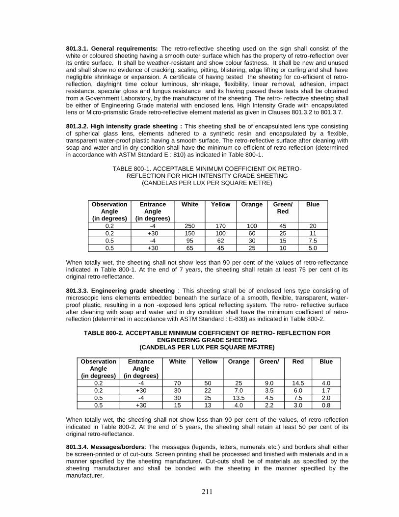
801.3.1. General requirements: The retro-reflective sheeting used on the sign shall consist of thewhite or coloured sheeting having a smooth outer surface which has the property of retro-reflection overits entire surface. It shall be weather-resistant and show colour fastness. It shall be new and unusedand shall show no evidence of cracking, scaling, pitting, blistering, edge lifting or curling and shall havenegligible shrinkage or expansion. A certificate of having tested the sheeting for co-efficient of retro-reflection, day/night time colour luminous, shrinkage, flexibility, linear removal, adhesion, impactresistance, specular gloss and fungus resistance and its having passed these tests shall be obtainedfrom a Government Laboratory, by the manufacturer of the sheeting. The retro- reflective sheeting shallbe either of Engineering Grade material with enclosed lens, High Intensity Grade with encapsulatedlens or Micro-prismatic Grade retro-reflective element material as given in Clauses 801.3.2 to 801.3.7.
801.3.2. High intensity grade sheeting : This sheeting shall be of encapsulated lens type consistingof spherical glass lens, elements adhered to a synthetic resin and encapsulated by a flexible,transparent water-proof plastic having a smooth surface. The retro-reflective surface after cleaning withsoap and water and in dry condition shall have the minimum co-efficient of retro-reflection (determinedin accordance with ASTM Standard E : 810) as indicated in Table 800-1.
TABLE 800-1. ACCEPTABLE MINIMUM COEFFICIENT OK RETRO-REFLECTION FOR HIGH INTENSITY GRADE SHEETING
(CANDELAS PER LUX PER SQUARE METRE)
ObservationAngle
(in degrees)
EntranceAngle
(in degrees)
White Yellow Orange Green/Red
Blue
0.2 -4 250 170 100 45 200.2 +30 150 100 60 25 110.5 -4 95 62 30 15 7.50.5 +30 65 45 25 10 5.0
When totally wet, the sheeting shall not show less than 90 per cent of the values of retro-reflectanceindicated in Table 800-1. At the end of 7 years, the sheeting shall retain at least 75 per cent of itsoriginal retro-reflectance.
801.3.3. Engineering grade sheeting : This sheeting shall be of enclosed lens type consisting ofmicroscopic lens elements embedded beneath the surface of a smooth, flexible, transparent, water-proof plastic, resulting in a non -exposed lens optical reflecting system. The retro- reflective surfaceafter cleaning with soap and water and in dry condition shall have the minimum coefficient of retro-reflection (determined in accordance with ASTM Standard : E-830) as indicated in Table 800-2.
TABLE 800-2. ACCEPTABLE MINIMUM COEFFICIENT OF RETRO- REFLECTION FORENGINEERING GRADE SHEETING
(CANDELAS PER LUX PER SQUARE MFJTRE)
ObservationAngle
(in degrees)
EntranceAngle
(in degrees)
White Yellow Orange Green/ Red Blue
0.2 -4 70 50 25 9.0 14.5 4.00.2 +30 30 22 7.0 3.5 6.0 1.70.5 -4 30 25 13.5 4.5 7.5 2.00.5 +30 15 13 4.0 2.2 3.0 0.8
When totally wet, the sheeting shall not show less than 90 per cent of the values, of retro-reflectionindicated in Table 800-2. At the end of 5 years, the sheeting shall retain at least 50 per cent of itsoriginal retro-reflectance.
801.3.4. Messages/borders: The messages (legends, letters, numerals etc.) and borders shall eitherbe screen-printed or of cut-outs. Screen printing shall be processed and finished with materials and in amanner specified by the sheeting manufacturer. Cut-outs shall be of materials as specified by thesheeting manufacturer and shall be bonded with the sheeting in the manner specified by themanufacturer.
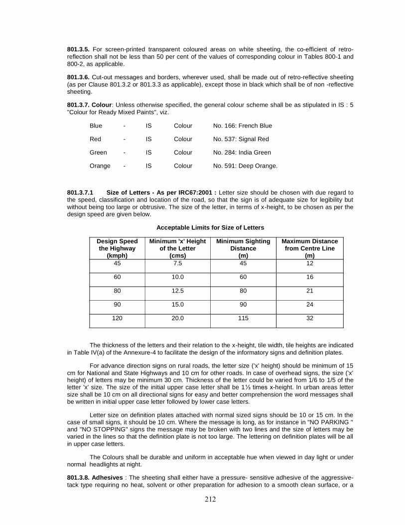
801.3.5. For screen-printed transparent coloured areas on white sheeting, the co-efficient of retro-reflection shall not be less than 50 per cent of the values of corresponding colour in Tables 800-1 and800-2, as applicable.
801.3.6. Cut-out messages and borders, wherever used, shall be made out of retro-reflective sheeting(as per Clause 801.3.2 or 801.3.3 as applicable), except those in black which shall be of non -reflectivesheeting.
801.3.7. Colour: Unless otherwise specified, the general colour scheme shall be as stipulated in IS : 5"Colour for Ready Mixed Paints", viz.
Blue - IS Colour No. 166: French Blue
Red - IS Colour No. 537: Signal Red
Green - IS Colour No. 284: India Green
Orange - IS Colour No. 591: Deep Orange.
801.3.7.1 Size of Letters - As per IRC67:2001 : Letter size should be chosen with due regard tothe speed, classification and location of the road, so that the sign is of adequate size for legibility butwithout being too large or obtrusive. The size of the letter, in terms of x-height, to be chosen as per thedesign speed are given below.
Acceptable Limits for Size of Letters
Design Speedthe Highway
(kmph)
Minimum 'x' Heightof the Letter
(cms)
Minimum SightingDistance
(m)
Maximum Distancefrom Centre Line
(m)45 7.5 45 12
60 10.0 60 16
80 12.5 80 21
90 15.0 90 24
120 20.0 115 32
The thickness of the letters and their relation to the x-height, tile width, tile heights are indicatedin Table IV(a) of the Annexure-4 to facilitate the design of the informatory signs and definition plates.
For advance direction signs on rural roads, the letter size (’x’ height) should be minimum of 15cm for National and State Highways and 10 cm for other roads. In case of overhead signs, the size (’x’height) of letters may be minimum 30 cm. Thickness of the letter could be varied from 1/6 to 1/5 of theletter ’x’ size. The size of the initial upper case letter shall be 1⅓ times x-height. In urban areas lettersize shall be 10 cm on all directional signs for easy and better comprehension the word messages shallbe written in initial upper case letter followed by lower case letters.
Letter size on definition plates attached with normal sized signs should be 10 or 15 cm. In thecase of small signs, it should be 10 cm. Where the message is long, as for instance in "NO PARKING "and "NO STOPPING" signs the message may be broken with two lines and the size of letters may bevaried in the lines so that the definition plate is not too large. The lettering on definition plates will be allin upper case letters.
The Colours shall be durable and uniform in acceptable hue when viewed in day light or undernormal headlights at night.
801.3.8. Adhesives : The sheeting shall either have a pressure- sensitive adhesive of the aggressive-tack type requiring no heat, solvent or other preparation for adhesion to a smooth clean surface, or a
lack free adhesive activated by heat, applied in a heat-vacuum applicator, in a manner recommendedby the sheeting manufacturer. The adhesive shall be protected by an easily removable liner (removableby peeling without soaking in water or other solvent) and shall be suitable for the type of material of thebase plate used for the sign. The adhesive shall form a durable bond to smooth, corrosion and weatherresistant surface of the base plate such that it shall not be possible to remove the sheeting from thesign base in one piece by use of sharp instrument. In case of pressure-sensitive adhesive sheeting, thesheeting shall be applied in accordance with the manufacturer’s Specifications. Sheeting withadhesives requiring use of solvents or other preparation for adhesive shall be applied strictly inaccordance with the manufacturer’s instructions.
801.3.9. Refurbishment : Where existing signs are specified for refurbishment, the sheeting shall havea semi-rigid aluminium backing pre-coated with aggressive-tack type pressure sensitive adhesive. Theadhesive shall be suitable for the type of material used for the sign and should thoroughly bond withthat material.
801.3.10. Fabrication :
801.3.10.1. Surface to be reflectorised shall be effectively prepared to receive the retro-reflectivesheeting. The aluminium sheeting shall be de-greased. either by acid or hot alkaline etching and allscale/dust removed to obtain a smooth plain surface before the application of retro- reflective sheeting.If the surface is rough, approved surface primer may be used. After cleaning, metal shall not be handled, except by suitable device or clean canvas gloves, between all cleaning and preparationoperation and application of reflective sheeting/primer. There shall be no opportunity for metal to comein contact with grease, oil or other contaminants prior to the application of retro-reflective sheeting.
801.3.10.2. Complete sheets of the material shall be used on the signs except where it is unavoidable;at splices, sheeting with pressure sensitive adhesives shall be overlapped not less than 5 mm. Sheetingwith heat-activated adhesives may be spliced with an overlap not less than 5 mm or butted with a gapnot exceeding 0.75 mm. Where screen printing with transparent colours is proposed, only butt jointingshall be used. The material shall cover the sign surface evenly and shall be free from twists, cracks andfolds. Cut-outs to produce legends and borders shall be bonded with the sheeting in the mannerspecified by the manufacturer.
801.3.11. Warranty and durability : The Contractor shall obtain from the manufacturer a seven -yearwarranty for satisfactory field performance including stipulated retro-reflectance of the retro-reflectivesheeting of high intensity grade and a five year warranty for the adhesive sheeting of engineeringgrade, and submit the same to the Engineer. In addition, a seven year and a five year warranty forsatisfactory in- field performance of the finished sign with retro-reflective sheeting of high intensitygrade and engineering grade respectively, inclusive-of the screen printed or cut out letters/legends aridtheir bonding to the retro-reflective sheeting shall be obtained from the Contractor/supplier and passedon to the Engineer, The Contractor/supplier shall also furnish a certification that the signs and materialssupplied against the assigned work meets all the stipulated requirements and carry the stipulatedwarranty.
Processed and applied in accordance with recommended procedures, the reflective material shall beweather resistant and, following cleaning, shall show no appreciable discolouration, cracking, blisteringor dimensional change and shall not have less than 50 per cent of the specified minimum reflectiveintensity values (Tables 800-1 and 800-2) when subjected to accelerated weathering for 1000 hours,using type E or EH Weatherometer (AASHTO Designation M 268).
801.4. Installation
801.4.1. Sign posts, their foundations and sign mountings shall be so constructed as to hold these in aproper and permanent position against the normal storm wind toads or displacement by vandalism.Normally, signs with an area upto 0.9 sq. m. shall be mounted on a single post, and for greater area twoor more supports shall be provided. Sign supports may be of mild steel, reinforced concrete orgalvanised iron (G.I). Post-end(s) shall be firmly fixed to the ground by means of property designedfoundation. The work of foundation shall conform to relevant Specifications as specified.
801.4.2. All components of signs and supports, other than the reflective portion and G.I. posts shall bethoroughly descaled, cleaned, primed and painted with two coats of epoxy paint. Any part of mild steel(M.S.) post below ground shall be painted with three coats of red lead paint.

801.4.3. The signs shall be fixed to the posts by welding in the case of steel posts and by bolts andwashers of suitable size in the case of reinforced concrete or G.I. posts. After the nuts have beentightened, the tails of the bolts shall be furred over with a hammer to prevent removal.
801.5. Measurements for Payment
The measurement of standard cautionary, mandatory and information signs shall be in numbers ofdifferent types of signs supplied and fixed, while for direction and place identification signs, these shallbe measured by area in square metres.
801.6. Rate
The Contract unit rate shall be payment in full for the cost of making the road sign, including allmaterials, installing it at the site and incidentals to complete the work in accordance with theSpecifications.
LIST OF MANDATORY/REGULATORY SIGNS
1. Stop and Give Way Signs(i) Stop(ii) Give Way
2. Prohibitory Signs(i) Straight Prohibited/No Entry(ii) One Way(iii) Vehicle Prohibited in Both Directions(iv) All Motor Vehicles(v) Truck Prohibited(vi) Bullock Cart and Hand Cart Prohibited(vii) Bullock Cart Prohibited(viii) Tonga Prohibited(ix) Hand Cart Prohibited(x) Cycle Prohibited(xi) Pedestrian Prohibited(xii) Right/Left Turn Prohibited(xiii) U-turn Prohibited(xiv) Overtaking Prohibited(xv) Horn Prohibited
3. No Parking and No Stopping Signs(i) No Parking(ii) No Stopping/Standing
4. Speed Limit and Vehicle Control Signs(i) Speed Limit(ii) Width Limit(iii) Height Limit(iv) Length Limit(v) Load Limit(vi) Axle Load Limit
5. Restriction Ends Signs6. Compulsory Direction Control and Other Signs
(i) Compulsory Turn Left/Right(ii) Compulsory Ahead Only

(iii) Compulsory Turn Right/Left Ahead(iv) Compulsory Ahead or Turn Right(v) Compulsory Ahead or Turn Left(vi) Compulsory Keep Left(vii) Compulsory Cycle Track(viii) Compulsory Sound Horn(ix) Pedestrians Only(xi) Buses only
LIST OF CAUTIONARY/WARNING SIGNS
1. Right Hand/Left Hand Curve2. Right/Left Hairpin Bend3. Right/Left Reverse Bend4. Steep Ascent/Descent5. Narrow Bridge6. Narrow Road Ahead7. Road Widens Ahead8. Gap in Median9. Slippery Road10. Loose Gravel11. Cycle Crossing12. Pedestrian Crossing13. School14. Cattle15. Men at Work16. Falling Rocks17. Ferry18. Cross Roads19. Side Road20. T-Intersection21. Y-Intersection22. Staggered Intersection23. Major Road Ahead24. Roundabout25. Dangerous Dip26. Rumble Strip27 Barrier Ahead28. Unguarded Railway Crossing29. Guarded Railway Crossing30. Speed Breaker Ahead31 Traffic Signal Ahead32. Runway Ahead33. End of Dual Carriageway34. Start of Dual Carriageway35. Series of Bends36. Overhead Cables Ahead

37. Quayside or River Bank38. Two Way Operation Ahead39. Lane Closure Ahead40 Traffic Diversion on Dual Carriageway41 Sudden Side Winds Ahead42 Reduced Carriageway43. Rough Road
LIST OF INFORMATORY SIGNS
1. Direction and Place Identification Signs(i) Advance Direction(ii) Destination(iii) Direction(iv) Reassurance(v) Place Identification(vi) Truck Lay Bye(vii) Toll Booth Ahead
2. Facility Information Signs(i) Public Telephone(ii) Filling Station (Petrol Pump)(iii) Hospital(iv) First Aid Post(v) Eating Place(vi) Light Refreshment(vii) Resting Place
3. Other Useful Information Signs(i) No Through Road(ii) No Through Side Road(iii) Informatory Sign for Pedestrian Subway(iv) Repair Facilities(v) Airport(vi) Police Station(vii) Railway Station(viii) Bus Lane Signs(ix) Bus Stop(x) Taxi Stand(xi) Auto Rickshaw Stand(xii) Cycle Rickshaw Stand
4. Parking Signs
5. Flood Gauge
802. OVERHEAD SIGNS
802.1. General
802.1.1. Overhead signs may be used in lieu of, or as an adjunct to, ground signs where the situationso warrants for proper information and guidance of the road user. The following conditions may beconsidered while deciding about the provision of overhead signs:
(1) Traffic volume at or near capacity
(2) Complex interchange design
(3) Three or more lines in each direction
(4) Restricted sight distance
(5) Closely spaced interchanges
(6) Multi-lane exits
(7) Large percentage of commercial vehicles
(8) High speed traffic
(9) Consistency of sign message location through a series of interchanges
(10) Insufficient space for ground mounted signs
(11) Background of street lighting
(12) Distances of important places enroute highways at suitable intervals,
802.1.2. From safety and aesthetic standpoints, overhead signs shall be mounted on overhead bridgestructures wherever possible. Where these are required to be provided at some other locations, thesupport system should be properly designed based on sound engineering principles, to safely sustainthe dead load, live load and wind load on the completed sign system. For this purpose, the overheadsigns shall be designed to withstand a wind loading of 150 kg/m1 normal to the face of the sign and 30kg/m1 transverse to the face of the sign. In addition to the dead load of the structure, walkway loadingof 250 kg concentrated live load shall also be considered for the design of the overhead sign structure.
802.2. Height
Overhead signs shall provide a vertical clearance of not less than 5.5 m over the entire width of thepavement and shoulders except where a lesser vertical clearance is used for the design of otherstructures. The vertical clearance to overhead sign structures or supports need not be greater than 300mm in excess of the minimum design clearance of other structures.
802.3. Lateral Clearance
802.3.1. The minimum clearance outside the usable roadway shoulder for expressway signs mountedat the road side or for overhead sign supports either to the right or left side of the roadway shall be 1.80m. This minimum clearance of 1.80 m shall also apply outside of an uncountable kerb. Wherepracticable, a sign should not be less than 3 m from the edge of the nearest traffic lane. Large guidesigns should be farther removed preferably 9 m or more from the nearest traffic lane, unless otherwisespecified. Lesser clearances, but not generally less than 1.80m, may be used on connecting roadwaysor ramps at inter-changes.
802.3.2. Where a median is 3.6 m or less in width, consideration should be given to spanning over bothroadways without a central support. Where overhead sign supports cannot be placed at a safe distanceaway from the line of traffic or in an otherwise protected site, they should either be so designed as tominimise the impact forces or protect motorists adequately by a physical barrier or guard rail of suitabledesign.
802.4. Number of Signs at an Overhead Installation In no case should there be more than three signsdisplayed at any one location, including regulatory or warning signs, either on the on the over headstructure or on its support.
802.5. Materials for Overhead Sign and Support Structure
802.5.1. Aluminium alloy or galvanized steel to be used as truss design supports shall conform torelevant IS. These shall be of sections and type as per structural design requirements as shown on theplans.
802.5.2. After steel trusses have been fabricated and all required holes punched or drilled on both thehorizontal truss unites and the vertical and support units, they shall be galvanized in accordance with ISSpecifications.
802.5.3. Where aluminium sheets are used for road signs, they shall be of smooth, hard and corrosionresistant aluminium alloy conforming to IS 736. Material Designation 24345 or 1900. The thickness ofsheet as 1.5mm.
802.5.4. High Strength bolts shall conform to IS: 1367 whereas precision bolts, nuts etc, shall conformto IS: 1364.
802.5.5. Plates and support sections for sign posts shall conform to IS: 266 and IS: 2062.
802.5.6. The overhead signs shall be reflectorised with high intensity retro-reflective sheeting preferablyof encapsulated lens type.
802.6. Size, Locations, etc. of Signs
802.6.1. The size of the signs, letters and their placements shall be as specified in the ContractDrawings and Specifications.
802.6.2. In the absence of details or for any missing details in the Contract documents, the signs shallbe provided as directed by the Engineer.
802.7. Installation
802.7.1. The supporting structure and signs shall be fabricated and erected as per details given in theplans.
802.7.2. Sign posts, their foundations and sign mountings shall be as constructed as to hold signs in aproper and permanent position to adequately resist swaying in the wind or displacement by vandalism.
802.7.3. The work of construction of foundation for sign supports including excavation and backfill,forms, steel reinforcement, concrete and its placement shall conform to the relevant Specificationsgiven in these Specifications.
802.7.4. The structures shall be erected with the specified camber and in such a manner as to preventexcessive stresses, injury and defacement.
802.7.5. Brackets shall be provided for mounting signs of the type to be supported by the structure. Forbetter visibility, they shall be adjustable to permit mounting the sign faces at any angle between a trulyvertical position and three degree from vertical. This angle shall be obtained by rotating the front loweredge of the sign forward. All brackets shall be of a length equal to the heights of the signs beingsupported.
802.7.6. Before erecting support structures, the bottom of each base plate shall he protected with anapproved material which will adequately prevent any harmful reaction between the plate and theconcrete.
802.7.7. The end supports shall be plumbed by the use of levelling nuts and the space between thefoundation and base plate shall he completely filled with an anti -shrink grout.
802.7.8. Anchor bolts for sign supports shall be set to proper locations and elevation with templates aridcarefully checked after construction of the sign foundation arid before the concrete has set.
802.7.9. All nuts on aluminium trusses, except those used on the flanges, shall be tightened only untilthey are snug. This includes the nuts on the anchor bolts. A thread lubricant shall be used with eachaluminium nut.
802.7.10. All nuts o galvanized steel trusses, with the exception of high strength bolt connections, shallbe tightened only to a snug condition.
802.7.11. Field welding shall not be permitted.
802.7.12. After installation of signs is complete, the sign shall be inspected by the Engineer. If specularreflection is apparent on any sign, its positioning shall be adjusted by the Contractor to eliminate orminimize this condition.
802.8. Measurements for Payment
802.8.1. Aluminium or steel overhead sign structure will be measured for payment by the specific unit(each) complete in place or for each component of the overhead sign structure as indicated in the Bill ofQuantities and the detailed drawing(s).
802.8.2. Flat sheet aluminium signs with retro-reflective sheeting thereon shall be measured forpayment by the square metre for each thickness, complete in place.
802.9. Rate
802.9.1. The structural steel part of the overhead sign shall be measured in tonnes while the sign boardshall be measured in sq. m. Other items like excavation for foundation and concrete in foundation to bemeasured and paid in cu. m. separately. The Contract unit rate for overhead sign structure shall bepayment in full compensation for furnishing all labour, materials, tools, equipment, excavation,fabrication and installation and all other incidental costs necessary to complete the work to theSpecifications.
802.9.2. The Contract unit rate for aluminium sheet signs shall include the cost of making the signincluding all materials and fixing the same in position and all other incidental costs necessary tocomplete the work to the Specifications.
803. ROAD MARKINGS
803.1. General
The colour, width and layout of road markings shall be in accordance with the Code of Practice forRoad Markings with paints, IRC : 35, and as specified in the drawings or as directed by the Engineer.
803.2. Materials
Road markings shall be of ordinary road marking paint, hot applied thermoplastic compound, orreflectorised paint as specified in the item and the material shall meet the requirements as specifiedbelow.
803.3. Ordinary Road Marking Paint
803.3.1. Ordinary paint used for road marking shall conform to Grade I as per IS: 164.
803.3.2. The road marking shall preferably be laid with appropriate road marking machinery.
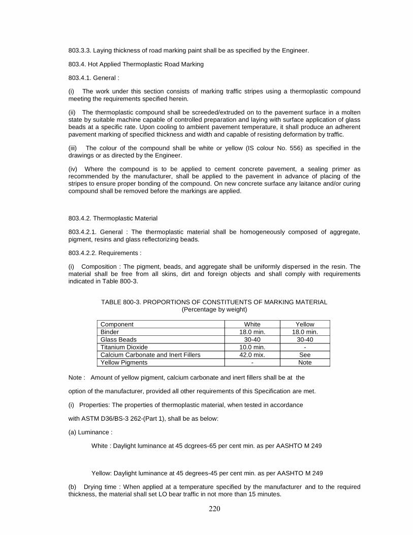
803.3.3. Laying thickness of road marking paint shall be as specified by the Engineer.
803.4. Hot Applied Thermoplastic Road Marking
803.4.1. General :
(i) The work under this section consists of marking traffic stripes using a thermoplastic compoundmeeting the requirements specified herein.
(ii) The thermoplastic compound shall be screeded/extruded on to the pavement surface in a moltenstate by suitable machine capable of controlled preparation and laying with surface application of glassbeads at a specific rate. Upon cooling to ambient pavement temperature, it shall produce an adherentpavement marking of specified thickness and width and capable of resisting deformation by traffic.
(iii) The colour of the compound shall be white or yellow (IS colour No. 556) as specified in thedrawings or as directed by the Engineer.
(iv) Where the compound is to be applied to cement concrete pavement, a sealing primer asrecommended by the manufacturer, shall be applied to the pavement in advance of placing of thestripes to ensure proper bonding of the compound. On new concrete surface any laitance and/or curingcompound shall be removed before the markings are applied.
803.4.2. Thermoplastic Material
803.4.2.1. General : The thermoplastic material shall be homogeneously composed of aggregate,pigment, resins and glass reflectorizing beads.
803.4.2.2. Requirements :
(i) Composition : The pigment, beads, and aggregate shall be uniformly dispersed in the resin. Thematerial shall be free from all skins, dirt and foreign objects and shall comply with requirementsindicated in Table 800-3.
TABLE 800-3. PROPORTIONS OF CONSTITUENTS OF MARKING MATERIAL(Percentage by weight)
Component White YellowBinder 18.0 min. 18.0 min.Glass Beads 30-40 30-40Titanium Dioxide 10.0 min. -Calcium Carbonate and Inert Fillers 42.0 mix. SeeYellow Pigments - Note
Note : Amount of yellow pigment, calcium carbonate and inert fillers shall be at the
option of the manufacturer, provided all other requirements of this Specification are met.
(i) Properties: The properties of thermoplastic material, when tested in accordance
with ASTM D36/BS-3 262-(Part 1), shall be as below:
(a) Luminance :
White : Daylight luminance at 45 dcgrees-65 per cent min. as per AASHTO M 249
Yellow: Daylight luminance at 45 degrees-45 per cent min. as per AASHTO M 249
(b) Drying time : When applied at a temperature specified by the manufacturer and to the requiredthickness, the material shall set LO bear traffic in not more than 15 minutes.

(c) Skid resistance : not less than 45 as per BS 6044.
(d) Cracking resistance at low temperature : The material shall show no cracks on application toconcrete blocks.
(e) Softening point : 102.5 ± 9,5° C as per ASTM D 36.
(f) How resistance : Not more than 25 per cent as per AASHTO M 249.
(g) Yellowness index (for white thermoplastic paint): not more than 0.12 as per AASHTO M 249
(iii) Storage life : The material shall meet the requirements of these Specifications for a period of oneyear. The thermoplastic material must also melt uniformly with no evidence of skins or unmeltedpanicles for the one year storage period. Any material not meeting the above requirements shall bereplaced by the manufacturer/ supplier/Contractor.
(iv) Reflectorisation : Shall be achieved by incorporation of beads, the grading and other properties ofthe beads shall be as specified in Clause 803.4.3.
(v) Marking : Each container of the thermoplastic material shall be clearly and indelibly marked withthe following information:
1. The name, trade mark or other means of identification of manufacturer
2. Batch number
3. Date of manufacture
4. Colour (white or yellow)
5. Maximum application temperature and maximum safe heating temperature.
(vi) Sampling and testing: The thermoplastic material shall be sampled and tested in accordance withthe appropriate ASTM/BS method. The Contractor shall furnish to the Employer a copy of certified testreports from the manufacturers of the thermoplastic material showing results of all tests specified hereinand shall certify that the material meets all requirements of this Specification.
803.4.3. Reflectorising glass beads
803.4.3.1. General : This Specification covers two types of glass beads 10 be used for the production ofreflectorised pavement markings.
Type 1 beads are those which are a constituent of the basic thermoplastic compound videTable 800-3 and Type 2 beads are those which are to be sprayed on the surface vide Clause 803.6,3.
803.4.3.2, The glass beads shall be transparent, colourless and free from milkiness, dark particles andexcessive air inclusions.
These shall conform to the requirements spelt out in Clause 803.4.3.3,
803.4.3.3. Specific requirements
A. Gradation: The glass beads shall meet the gradation requirements for the two types as given inTable 800-4. TABLE 800-4.
GRADATION REQUIREMENTS FOR GLASS BEADS
Sieve size Per cent retainedType 1 Type 2
1.18 mm 0 to 3 -
580 micron 5 to 20 0 to 20600 - do - - 5 to 20425 - do - 65 to 95 -300 - do - - 30 to 75180 - do - 0 to 10 10 to 30
below 180 micron - 0 to 15
B. Roundness: The glass beads shall have a minimum of 70 per cent true spheres.
C. Refractive index: The glass beads shall have a minimum refractive index of 1.50.
D. Free flowing properties : The glass beads shall be free of hard lumps and clusters and shalldispense readily under any conditions suitable for paint striping. They shall pass the free flow-test.
803.4.3.4. Test methods: The specific requirements shall be tested with the following methods:
(i) Free-flow test- Spread 100 grams of beads evenly in a 100 mm diameter glass dish. Place the dishin a 250 mm inside diameter desiccator which is filled within 25 mm of the lop of a desiccator plate withsulphuric acid water solution (specific gravity 1.10). Cover the desiccator and let it stand for 4 hours at20 lo 29 degree C. Remove sample from desiccator, transfer beads to a pan aid inspect for lumps orclusters. Then pour beads into a clean, dry glass funnel having a 100 mm stern and 6 mm orifice. Ifnecessary, initiate flow by lightly tapping the funnel. The glass spheres shall be essentially free oflumps and clusters and shall flow freely through the funnel.
(ii) The requirements of gradation, roundness and refractive index of glass beads and the amount ofglass beads in the compound shall be tested as per B3 6088 and BS 3262 (Part I).
(iii) The Contractor shall furnish to the Employer a copy of certified test reports from the manufacturerof glass beads obtained from a reputed laboratory showing results of all tests specified herein mid shallcertify that the material meets all requirement of this Specification. However, if so required, these testsmay be carried out as directed by the Engineer.
803.4.4. Application properties of thermoplastic material
803.4.4.1. The thermoplastic material shall readily get screeded/ extruded at temperatures specified bythe manufacturers for respective method of application to produce a tine of specified thickness whichshall be continuous and uniform in shape having clear and sharp edges.
803.4.4.2. The material upon heating to application temperatures, shall not exude fumes, which aretoxic, obnoxious or injurious to persons or property.
803.4.5. Preparation:
(i) The material shall be melted in accordance with the manufacturer’s instructions in a healer filledwith a mechanical stirrer to give a smooth consistency to the thermoplastic material lo avoid localoverheating. The temperature of the mass shall be within the range specified by the manufacturer, andshall on no account be allowed lo exceed the maximum temperature stated by the manufacturer. Themolten material should be used as expeditiously as possible and for thermoplastic material which hasnatural binders or is otherwise sensitive lo prolonged heating, the material shall not be maintained in amol ten condition for more than 4 hours.
(ii) After transfer lo the laying equipment, the material shall be maintained within the temperaturerange specified by the manufacturer for achieving the desired consistency for laying.
803.4.6. Properties of finished road marking :
(a) The stripe shall not be slippery when wet.
(b) The marking shall not lift from the pavement in freezing weather.
(c) After application and proper drying, the stripe shall show no appreciable deformation ordiscolouration under traffic and under road temperatures upto 60°C.
(d) The marking shall not deteriorate by contact with sodium chloride, calcium chloride or oil drippingsfrom traffic.
(e) The stripe or marking shall maintain its original dimensions and position. Cold ductility of thematerial shall be such as to permit normal movement with the road surface without chopping orcracking.
(f) The colour of yellow marking shall conform 10 IS Colour No. 356 as given in IS: 164.
803.5. Reflectorised Paint
Reflectorised paint, if used, shall conform to the Specification by the manufacturers and approved bythe Engineer. Reflectorising glass beads for reflectorising paints where used shall conform to therequirement of Clause 803.4,3.
803.6. Application
803.6.1. Marking shall be done by machine. For locations where painting cannot be done by machine,approved manual methods shall be used with prior approval of the Engineer. The Contractor shallmaintain control over traffic while painting operations are in progress so as to cause minimuminconvenience to traffic compatible with protecting the workmen.
803.6.2. The thermoplastic material shall be applied hot either by screeding or extrusion process. Aftertransfer to the laying apparatus, the material shall be laid at a temperature within the range specified bythe manufacturer for the particular method of laying being used. The paint shall be applied using ascreed or extrusion machine.
803.6.3. The pavement temperature shall not be less than 10°C during application. All surfaces to bemarked shall be thoroughly cleaned of all dust, dirt, grease, oil and all other foreign matter beforeapplication of the paint.
The material, when formed into traffic stripes, must be readily renewable by placing an overlayof new material directly over an old line of compatible material. Such new material shall so bond itself tothe old line that no splitting or separation takes place.
Thermoplastic paint shall be applied in intermittent or continuous lines of uniform thickness of atleast 2.5 mm unless specified otherwise. Where arrows or letters are to be provided, thermoplasticcompound may be hand-sprayed. In addition to the beads included in the material, a further quantity ofglass beads of Type 2, conforming to the above noted Specification shall be sprayed uniformly into amono-layer on to the hot paint line in quick succession of the paint spraying operation. The glass beadsshall be applied at the rate of 250 grams per square metre area.
803.6.4. The minimum thickness specified is exclusive of surface applied glass beads. The method ofthickness measurement shall be in accordance with Appendices B and C of BS - 3262 (Part 3).
803.6.5. The finished lines shall be free from ruggedncss on sides and ends and be parallel to thegeneral alignment of the carriageway. The upper surface of the lines shall be level, uniform and freefrom streaks.
803.7. Measurements for Payment
803.7.1. The painted markings shall be measured in sq. metres of actual area marked (excluding thegaps, if any).
803.7.2. In respect of markings like directional arrows and lettering, etc., the measurement shall be bynumbers.
803.8. Rate
The Contract unit rate for road markings shall be payment in full compensation for furnishing all labour,materials, tools, equipment, including all incidental costs necessary for carrying out the work at the siteconforming to these Specifications complete as per the approved drawing(s) or as directed by theEngineer and all other incidental costs necessary to complete the work to these Specifications.
804. HECTOMETRE/KILOMETRE STONES
804.1. General
The work covers the supply, painting, lettering and fixing of distance measurement stones and shallinclude:
(i) Heciometre siones
(ii) Kilometre stones
(iii) 5th Kilometre siones
804.2. The dimensions of the stones and the size, colour, arrangement of letters and script shall be asper IRC : 26 "Type Designs for 200 Metre Stones" and IRC: 8 "Type Designs for Highway KilometreStones",
804.3. The hectometre/kilometre stones may be made of local stones, concrete or any other materialavailable locally and approved by the Engineer. The stones shall be bedded into the ground withadequate foundations as indicated in the drawings or in the relevant I.R.C. Specifications or as directedby the Engineer. The orientation and location of the stones shall be as indicated in the drawings or inthe relevant I.R.C. Specifications or as directed by the Engineer.
804.4. Measurements for Payment
The measurement will be in numbers of 200 metre, kilometre and 5th kilometre stones fixed at site.
804.5. Rate
The Contract unit rate for hectometre/kilometre/5th kilometre stones shall be payment in fullcompensation for furnishing all labour, materials, tools, equipment and making the stones, painting andlettering and fixing at site and all other incidental costs necessary to complete the work to theseSpecifications.
805. ROAD DELINEATORS
805.1. General
The work covers supplying and fixing roadway indicators, hazard markers and object markers.
805.2. The design, materials to be used and the location of the road delineators shall conform toRecommended Practice for Road Delineators, IRC: 79, and to relevant drawings or as otherwisedirected by the Engineer.
805.3. Measurements for Payment
The measurement shall be made in numbers of delineators fixed at site.
805.4. Rate
The Contract unit rate for Road Delineators shall be payment in full compensation for furnishing alllabour, materials, tools, equipment for preparing, supplying and fixing at site an d all oilier incidentalcosts necessary to complete the work to these Specifications.
806. BOUNDARY STONKS
806.1. General
The work comprises of supplying and fixing boundary stones as per designs and Specifications given inIRC: 25 "Type Designs for Boundary Stones" and at locations indicated in the drawings or-as directedby the Engineer.
806.2. Measurements for Payment
The measurement shall be made in numbers of boundary stones fixed at site.
806.3. Rate
The Contract unit rate for boundary stones shall be payment in full compensation for furnishing alllabour, materials, tools, equipment for preparing, supplying and fixing and all other incidental costsnecessary to complete the work to these Specifications.
807. FENCING
807.1. General
The work comprises of fixing Mild Steel (M.S.) posts and providing barbed wire fencing includingnecessary stays and entry gates as shown in the drawing (s) and as directed by the Engineer.
807.2. The M.S. posts shall conform to IS:226 and shall be of angle iron of size indicated in thedrawings. The angle iron shall be embedded in concrete to a sufficient depth below ground as indicatedin the drawings. The steel shall be fabricated and painted to conform to Section 1900 of theseSpecifications.
807.3. The barbed wire shall be of galvanised iron and shall conform to 15:278.
807.4. Entry gate(s) shall be made of M.S. rods or other metal as per the design shown in thedrawing(s).
807.5. Measurements for Payment
The measurement shall be in running metre of fencing including the entry gates.
807.6. Rate
The Contract unit rate for fencing shall be payment in full compensation for furnishing all labour,materials, tools, equipment for fabrication and fixing at site and all other incidental costs necessary tocomplete the work to these Specifications.
808. TUBULAR STEEL RAILING
808.1. General
The work shall consist of supplying, fixing and erecting tubular steel railings as shown on the drawingsand as directed by the Engineer.
808.2. The railings shall be of tubular steel in conformance to IS:1239. The fabrication and paintingexcept for the final coat shall be completed before despatch to the site. Prior to the painting, all surfacesshall be grit blasted to the satisfaction of the Engineer and pickled. The priming coat of paint shall beapplied as soon as the steel has dried.
808.3. The posts shall be vertical and of the type as shown in the drawing with a tolerance notexceeding 6 mm in a length of 3 m. The railing shall be erected true to line and grade.
808.4. Measurements for Payment
The railing shall be measured in linear metre from end to end along the face of the railing,including end and intermediate posts, with no deductions for gaps as shown on the drawings.
808.5. Rate
The Contract unit rate for Tubular Steel Railing shall be payment in full compensation forfurnishing all labour, materials, tools, equipment and plant required for fabrication, connection, oiling,painting, temporary erection, inspection, test and final erection at site and all other incidental costsnecessary to complete the work to these Specifications.
809. CONCRETE CRASH BARRIER
809.1. General
809.1.1. This work shall consist of construction, provision and installation of concrete crash barrier atthe edges of the road and median at locations and of dimensions as shown on the drawings or asdirected by the Engineer.
809.1.2. Concrete barrier shall generally be located on approaches to bridge structures, at locationswhere the embankment height is more than 3 metres and at horizontal curves.
809.2. Materials
809.2.1. All materials shall conform to Section 1000-Materials for Structures as applicable, and relevantClauses in Section 1600 shall govern the steel reinforcement. The concrete barriers shall beconstructed either by the "cast- in-place with fixed forms" method or the "extrusion or slip form" methodor a combination thereof at the Contractor’s option with the approval of the Engineer. Where "extrusionor slip form" method is adopted, full details of the method and literature shall be furnished.
809.2.2. Concrete barriers shall be constructed with M’20 grade concrete and with High Yield Strengthdeformed reinforcement conforming to IRC: 21.
809.2.3. An expansion joint with pre-moulded asphalt filler board shall be provided at the junction ofcrash barrier on structure and crash barrier on the fill. The crash barrier on the fill shall be constructedin pieces of length not exceeding 20 m, with pre-moulded asphalt filler board joints.
809.3. Construction Operations
809.3.1. The location of crash barrier shall be stri ctly adhered to as shown on the drawing and asdirected by the Engineer. Concrete crash barriers shall present a smooth, uniform appearance in theirfinal position, conforming to the horizontal and vertical lines shown on the plans or as ordered by theEngineer and shall be free of lumps, sags or other irregularities. The top and exposed faces of thebarriers shall conform to the specified tolerances, as defined in Clause 809.4, when tested with 3 mstraight edge, laid on the surface.
809.3.2. When concrete barriers are to be constructed on recently completed bridges, the height of thebarriers shall be adjusted to compensate for die camber and dead load deflection of the superstructure.The amount of adjustment shall be determined by the Engineer and shall be ordered before theconcrete is placed. Such barriers shall be placed after form work has been released and as long afterthe superstructure construction as possible without hampering the progress of the work.
809.3.3. Backfilling to the concrete barriers shall be compacted in layers to the compaction of thesurrounding earthwork.
809.4. Tolerance The overall horizontal alignment of rails shall not depart from the road alignment bymore than ± 30 mm, nor deviate in any two successive lengths from straight by more than 6 mm andthe faces shall not vary more than 12 mm from the edge of a 3 m straight edge. Barriers shall be at thespecified height as shown in die plans above the edge of the nearest adjacent carriageway or shoulder,within a tolerance of ± 30 mm.
809.5. Measurements for Payment
All barriers will be measured by linear metres of completed and accepted length \n place,corresponding end to end along the face of concrete barriers including approach and departure ends.
809.6. Rate
The Contract unit rate shall include full compensation for furnishing all labour, materials, tools,equipment and incidental costs necessary for doing all the work involved in constructing the concretebarrier complete in place in all respects as per these Specifications.
810. METAL BEAM CRASH BARRIER
810.1. General
810.1.1. This work shall consist of furnishing and erection of metal beam crash barrier of dimensionsand at locations as shown on the drawing (s) or as directed by the Engineer.
810.1.2. Metal beam crash barrier shall generally be located on approaches to bridge structures, atlocations where the embankment height is more than 3 metres and at horizontal curves.
810.2. Materials
810.2.1. Metal beam rail shall be corrugated sheet steel beams of the class, type, section and thicknessindicated on the plans. Railing posts shall be made of steel of the section, weight and length as shownon the plans. All complete steel rail elements, terminal sections, posts, bolts, nuts, hardware and othersteel fittings shall be galvanised. All elements of the railing shall be free from abrasions, rough or sharpedges and shall not be kinked, twisted or bent.
810.2.2. Steel beam elements and terminal sections shall be galvanised (zinc coated, 0.55 kg persquare metre, minimum single spot) unless otherwise specified. The galvanising on all other steel partsshall conform tp the relevant IS Specifications, All fittings (bolts, nuts, washers) shall conform to theIS:1367 and IS:1364. All galvanizing shall be done after fabrication.
810.2.3. Concrete for bedding and anchor assembly shall conform to Section 1700 of theseSpecifications.
810.3. Construction Operations
810.3.1. The line and grade of railing shall be true to that shown on the plans. The railing shall becarefully adjusted prior to fixing in place, to ensure proper matching at abutting joints arid correctalignment and camber throughout their length. Holes for field connections shall be drilled with the railingin place in the structure at proper grade and alignment.
810.3.2. Unless otherwise specified on the drawing, railing steel posts shall be given one shop coat ofpaint (primer) and three coats of paint on structural steel after erection, if the sections are notgalvanised. Any part of assembly below ground shall be painted with three coats of red lead paint.
810.3.3. Splices and end connections shall be of the type and designs specified or shown on the plansand shall be of such strength as to develop full design strength of the rail elements.
810.4. Installation of Posts
810.4.1. Holes shall be dug or drilled to the depth indicated on the plans or posts may be driven byapproved methods and equipment, provided these are erected in proper position and are free fromdistortion and burring or any other damage.
810.4.2. All post holes that are dug or drilled shall be of such size as will permit proper setting of theposts and allow sufficient room or backfilling and lapping.
810.4.3. Holes shall be backfilled with selected earth or stable materials in layers not exceeding 100mm thickness and each layer shall be thoroughly tamped and rammed. When backfilling and tamp arecompleted, the posts or anchors shall be held securely in place.
810.4.4. Post holes that are drilled in rock and holes for anchor posts shall be back filled with concrete.
810.4.5. Posts for metal beam guardrails on bridges shall be bolted to the structure as detailed on theplans. The anchor bolts shall be set to proper location and elevation with templates and carefullychecked.
810.5. Erection
810.5.1. All guardrail anchors shall be set and attachments made and placed as indicated on the plansor as directed by the Engineer.
810.5.2. All bolts or clips used for fastening the guardrail or fittings to the posts shall be drawn uptightly. Each bolt shall have sufficient length to extend atleast 6 mm through and beyond the full nut,except which such extensions might interfere with or endanger traffic in which case the bolts shall becut off flush with the nut.
810.5.3. All railings shall be erected, drawn and adjusted so that the longitudinal tension will be uniformthroughout the entire length of the rail.
810.6. Tolerance
The posts shall be vertical with a tolerance not exceeding 6 mm in a length of 3 metre. The railingbarrier shall be erected true to line and grade.
810.7. Measurements for Payment
810.7.1. Metal beam railing barriers will be measured by linearmetre of completed length as per plansand accepted in place. Terminals/anchors of various types shall be paid for by numbers.
810.7.2. No measurement for payment shall be made for projections or anchors beyond the end postsexcept as noted above. Furnishing and placing anchor bolts and/or devices for guard rail posts onbridges shall be Considered incidental to the construction and the costs thereof shall be included in theprice for other items of construction.
810.7.3. No measurement for payment will be made for excavation or backfilling performed inconnection with this construction.
810.8. Rate
The Contract unit rate shall include full compensation for furnishing of labour, materials, tools,equipments and incidental costs necessary for doing all the work involved in constructing the metalbeam rating barrier complete in place in all respects as per these Specifications.
811. ROAD TRAFFIC SIGNALS
811.1. General
The traffic signal, its configuration, size and location shall be in accordance with IRC: 93 and IS: 7537and as shown in the drawings or as directed by the Engineer. Prior to installation of signals, theContractor shall submit to the Engineer, for approval, detailed proposals showing the signal type, sizes,paint and structural details of the signal posts including control system.
811.2. The traffic signals shall have a complete electronic mechanism for controlling the operation oftraffic with an auxiliary manual controller. The time plan of signals shall be as per drawing and shall bemodified as directed by the Engineer.
811.3. Materials
The various materials and fabrication thereof shall conform to the following:
811.3.1. Signal foundation: The signal foundations shall be constructed as per Specifications given inClause 13 of IRC : 93 or as shown in the drawings.
811.3.2. Constructional requirements: The constructional requirements for post, signal head assembly,signal head, optical system, lamp and holder, visor, post, supports for overhead mounted signals,equipment housing, locks, inter-connecting cables, earthing, mains termination, controller electricalcomponents, etc., shall conform to IS: 7537 unless otherwise staled in IRC: 93. The post shall bepainted and protected as per Clause 3.7. of IS: 7537.
811.3.3. Optical requirements: The shape of all signal lenses shall be circular and shall be of specifiedcolour and size and as shown in the drawing. Quality of lenses, arrangement of lenses, illuminations,visibility and shielding of signals shall be as per relevant Clauses of IRC : 93 and 15:7537.
811.4. Tests
Tests shall be carried out on all components of traffic signal including tests on complete system for itsperformance as per relevant Clauses of IRC:93 and IS:7537.
811.5. Maintenance of Traffic Signals
It shall be the responsibility of the Contractor to provide for maintenance of the signal sectionsystem throughout the warranty period for at least five (5) years after installation and as per Clause 18of IRC : 93.
811.6. Measurements for Payment
The measurement for traffic signalisation system shall be by unit for complete work as specified and asper drawing for complete road junction.
811.7. Rate
The Contract unit rate for the traffic signalisation system as a whole shall be payment in fullcompensation for furnishing all labour, materials, tools, equipment for preparing, supplying, fixing atsite, testing and maintenance throughout warranty period and all other incidental costs necessary tocomplete and maintain the work to these Specifications.


CONTENT
Clause No Description901 GENERAL
902 CONTROL OF ALIGNMENT, LEVEL AND SURFACE REGULARITY
903 QUALITY CONTROL TESTS DURING CONSTRUCTION
901. GENERAL
901.1. All materials to be used, all methods adopted and all works performed shall be strictly inaccordance with the requirements of these Specifications. The Contractor shall set up a fieldlaboratory at locations approved by the Engineer and equip the same with adequate equipmentand personnel in order 10 carry out all required tests and Quality Control work as perSpecifications and/or as directed by the Engineer, The internal layout of the laboratory shall be asper Clause 121 and/or as directed by the Engineer. The list of equipment and the facilities to beprovided shall be got approved from the Engineer in advance.
901.2. The Contractor’s laboratory should be manned by a qualified Materials Engineer/CivilEngineer assisted by experienced technicians, and the set-up should be got approved by theEngineer.
901.3. The Contractor shall carry out quality control tests on the materials and work to thefrequency stipulated in subsequent paragraphs. In the absence of clear indications about methodand or frequency of tests for any item, the instructions of the Engineer shall be followed.
901.4. For satisfying himself about the quality of the materials and work, quality control tests willalso be conducted by the Engineer.(by himself, by his Quality Control Units or by any otheragencies deemed fit by him), generally to the frequency set forth ereinunder. Additional tests mayalso be conducted where, in the opinion of the Engineer, need for such tests exist. 901.5. TheContractor shall provide necessary co-operation and assistance in obtaining the samples for testsand carrying out the field tests as required by the Engineer from time to time. This may includeprovision of labour, attendants, assistance in packing and dispatching and any other assistanceconsidered necessary in connection with the tests.
901.6. For the work of embankment, sub grade and pavement, construction of subsequent layerof same or other material over the finished layer shall be done after obtaining permission from theEngineer. Similar permission from the Engineer shall be obtained in respect of all other items ofworks prior to proceeding with the next stage of construction.
901.7. The Contractor shall carry out modifications in the procedure of work, if found necessary,as directed by the Engineer during inspection. Works falling short of quality shall berectified/redone by the Contractor at his own cost, and defective work shall also be removed fromthe site of works by the Contractor at his own cost.
901.8. The cost of laboratory building including services, essential supplies like water, electricity,sanitary services and their maintenance and cost of all equipment, tools, materials, labour andincidentals to perform tests and other operations of quality control according to the Specificationrequirements shall be deemed to be incidental to the work and no extra payment shall be madefor the same. If, however, there is a separate item in the Bill of Quantities for setting up of alaboratory and installing testing equipment, such work shall be paid for separately.
901.9. For testing of samples of soils/soil mixes, granular materials, and mixes, bituminousmaterials and mixes, aggregates, cores etc., samples in the required quantity and form shall besupplied to the Engineer by the Contractor at his own cost.
901.10. For cement, bitumen, mild steel, an d similar other materials where essential tests are tobe carried out at the manufacturer’s plants or at laboratories other than the site laboratory, thecost of samples, sampling, testing and furnishing of test certificates shall be borne by theContractor. He shall also furnish the test certificates to the Engineer.
901.11. For testing of cement concrete at site during construction, arrangements for supply ofsamples, sampling, testing and supply of test results shall be made by the Contractor as per thefrequency and number of tests specified in the Handbook of Quality Control for Construction of
Roads and Runways (IRC: SP: 11) and relevant IS Codes or relevant clauses of theseSpecifications, the cost of which shall be borne by the Contractor.
901.12. The method of sampling and testing of materials shall be as required by the "Handbookof Quality Control for Construction of Roads and Runways" (IRC: SP: 11), and these MOSTSpecifications. Where they are contradicting, the provision in these Specifications shall befollowed. Where they are silent, sound engineering practices shall be adopted. The sampling andtesting procedure to be used shall be as approved by the Engineer and his decision shall be fin aland binding on the Contractor.
901.13. The materials for embankment construction shall be got approved from the Engineer. Theresponsibility for arranging and obtaining the land for borrowing or exploitation in any other wayshall rest with the Contractor who shall ensure smooth and uninterrupted supply of materials inthe required quantity during the construction period.
Similarly, the supply of aggregates for construction of road pavement shall be fromquarries approved by the Engineer, Responsibility for arranging uninterrupted supply of materialsfrom the source shall be that of the Contractor.
901.14. Defective MaterialsAll materials which the Engineer/his representative have determined as not conforming to therequirements of the Contract shall be rejected whether in place or not; they shall be removedimmediately from the site as directed. Materials, which have been subsequently corrected, shallnot be used in the work unless approval is accorded in writing by the Engineer. Upon failure ofthe Contractor to comply with any order of the Engineer/his representative, given under thisClause, the Engineer/his representative shall have authority to cause the removal of rejectedmaterial and to deduct the removal cost thereof from any payments due to the Contractor.
901.15. Imported MaterialsAt the time of submission of tenders, the Contractor shall furnish a list of materials/finishedproducts manufactured, produced or fabricated outside India which he proposes to use in thework. The Contractor shall not be entitled to extension of time for acts or events occurring outsideIndia and it shall be the Contractor’s responsibility to make timely delivery to the job site of allsuch materials obtained from outside India.
The materials imported from outside India shall conform to the relevant Specifications ofthe Contract. In case where materials/finished products are not covered by the Specifications inthe Contract, the details of Specifications proposed to be followed and the testing procedure a swell as laboratories/ establishments where tests are to be carried out shall be specifically broughtout and agreed to in the Contract.
The Contractor shall furnish to the Engineer a certificate of compliance of the testscarried out. In addition, certified mill test reports clearly identified to the lot of materials shall befurnished at the Contractor’s cost.
902. CONTROL OF ALIGNMENT, LEVEL AND SURFACE REGULARITY902.1. GeneralAll works performed shall conform to the lines, grades, and cross sections and dimensions shownon the drawings or as directed by the Engineer, subject to the permitted tolerances describedherein-after.
902.2. Horizontal AlignmentHorizontal alignments shall be reckoned with respect to the centre line of the carriageway asshown on the drawings. The edges of the carriageway as constructed shall be correct within atolerance of ± 10 mm there from. The corresponding tolerance for edges of the roadway andlower layers of pavement shall be ± 25 mm.
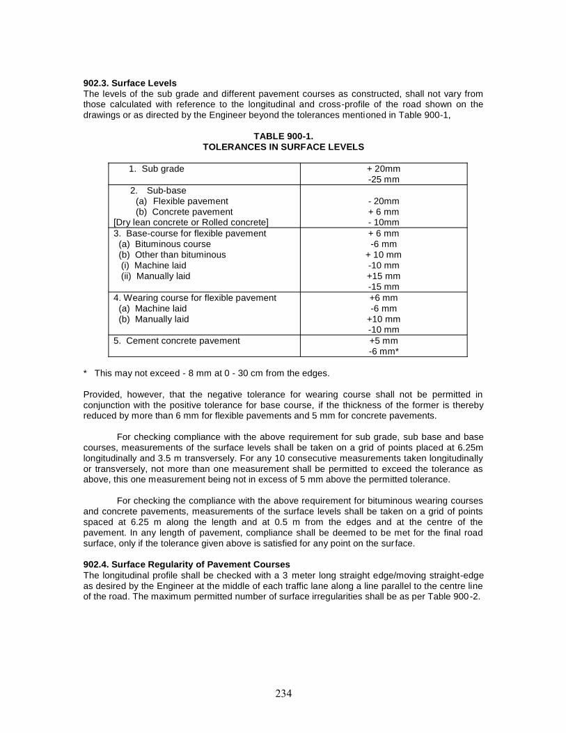
902.3. Surface LevelsThe levels of the sub grade and different pavement courses as constructed, shall not vary fromthose calculated with reference to the longitudinal and cross-profile of the road shown on thedrawings or as directed by the Engineer beyond the tolerances mentioned in Table 900-1,
TABLE 900-1.TOLERANCES IN SURFACE LEVELS
1. Sub grade + 20mm-25 mm
2. Sub-base(a) Flexible pavement(b) Concrete pavement
[Dry lean concrete or Rolled concrete]
- 20mm+ 6 mm- 10mm
3. Base-course for flexible pavement(a) Bituminous course(b) Other than bituminous(i) Machine laid(ii) Manually laid
+ 6 mm-6 mm
+ 10 mm-10 mm+15 mm-15 mm
4. Wearing course for flexible pavement(a) Machine laid(b) Manually laid
+6 mm-6 mm
+10 mm-10 mm
5. Cement concrete pavement +5 mm-6 mm*
* This may not exceed - 8 mm at 0 - 30 cm from the edges.
Provided, however, that the negative tolerance for wearing course shall not be permitted inconjunction with the positive tolerance for base course, if the thickness of the former is therebyreduced by more than 6 mm for flexible pavements and 5 mm for concrete pavements.
For checking compliance with the above requirement for sub grade, sub base and basecourses, measurements of the surface levels shall be taken on a grid of points placed at 6.25mlongitudinally and 3.5 m transversely. For any 10 consecutive measurements taken longitudinallyor transversely, not more than one measurement shall be permitted to exceed the tolerance asabove, this one measurement being not in excess of 5 mm above the permitted tolerance.
For checking the compliance with the above requirement for bituminous wearing coursesand concrete pavements, measurements of the surface levels shall be taken on a grid of pointsspaced at 6.25 m along the length and at 0.5 m from the edges and at the centre of thepavement. In any length of pavement, compliance shall be deemed to be met for the final roadsurface, only if the tolerance given above is satisfied for any point on the sur face.
902.4. Surface Regularity of Pavement CoursesThe longitudinal profile shall be checked with a 3 meter long straight edge/moving straight-edgeas desired by the Engineer at the middle of each traffic lane along a line parallel to the centre lineof the road. The maximum permitted number of surface irregularities shall be as per Table 900-2.
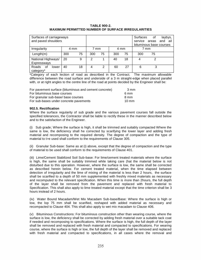
TABLE 900-2.MAXIMUM PERMITTED NUMBER OF SURFACE IRREGULARITIES
Surfaces of carriagewaysand paved shoulders
Surfaces of laybys,service areas and ailbituminous base courses
Irregularity 4 mm 7 mm 4 mm 7 mmLength(m) 300 75 300 75 300 75 300 75National Highways/Expressways
20 9 2 1 40 18 4 2
Roads of lowercategory*
40 18 4 2 60 27 6 3
*Category of each lection of road as described in the Contract. The maximum allowabledifference between the road surface and underside of a 3 m straight-edge when placed parallelwith, or at right angles to the centre line of the road at points decided by the Engineer shall be:
For pavement surface (bituminous and cement concrete) 3 mmFor bituminous base courses 6 mmFor granular sub-base/ base courses 8 mmFor sub-bases under concrete pavements 10 mm
902.5. RectificationWhere the surface regularity of sub grade and the various pavement courses fall outside thespecified tolerances, the Contractor shall be liable to rectify these in the manner described belowand to the satisfaction of the Engineer.
(i) Sub grade; Where the surface is high, it shall be trimmed and suitably compacted Where thesame is low, the deficiency shall he corrected by scarifying the lower layer and adding freshmaterial and recomposing to the required density. The degree of compaction and the type ofmaterial to t>e used shall conform to the requirements of Clause 305.
(ii) Granular Sub-base: Same as at (i) above, except that the degree of compaction and the typeof material to be used shall conform to the requirements of Clause 401.
(iii) Lime/Cement Stabilized Soil Sub-base: For lime/cement treated materials where the surfaceis high, the same shall be suitably trimmed while taking care (hat the material below is notdisturbed due to this operation. However, where the surface is low, the same shall be correctedas described herein below. For cement treated material, when the time elapsed betweendetection of irregularity and the lime of mixing of the material is less than 2 hours, the surfaceshall be scarified to a depth of 50 mm supplemented with freshly mixed materials as necessaryand recomputed to the relevant specification. When this time is more than 2hours, the full depthof the layer shall be removed from the pavement and replaced with fresh material toSpecification. This shall also apply to lime treated material except that the time criterion shall be 3hours instead of 2 hours.
(iv) Water Bound Macadam/Wet Mix Macadam Sub-base/Base: Where the surface is high orlow, the lop 75 mm shall be scarified, reshaped with added material as necessary andrecompacted to Clause 404. This shall also apply to wet mix macadam to Clause 406.
(v) Bituminous Constructions: For bituminous construction other than wearing course, where thesurface is low, the deficiency shall be corrected by adding fresh material over a suitable tack coatif needed and recomposing to specifications. Where the surface is high, the full depth of the layershall be removed and replaced with fresh material and compacted to specifications. For wearingcourse, where the surface is high or low, the full depth of the layer shall be removed and replacedwith fresh material and compacted to specifications, in all cases where the removal and
replacement of a bituminous layer is involved, the area treated shall not be less than 5 m inlength and not less than 3.5 m in width.
(vi) Dry Lean Concrete Sub-base/Rolled Cement Concrete; the defective length of the courseshall be removed Lo full depth and replaced with material conforming to Clauses 601 or 603, asapplicable. The area treated shall be at least 3 m long, not less than 1 lane wide and ex lend tothe full depth. Before relaying the course, the disturbed sub grade or layer below shall becorrected by leveling, watering and compacting.
(vii) Cement concrete pavement; the defective areas having surface irregularly exceeding 3 mmbut not greater than 6 mm may be rectified by bump cutting or scrabbling or grinding usingapproved equipment. When required by the Engineer, areas which have been reduced in level bythe above operation(s) shall be retextured in an approved manner either by cutting grooves (5mm deep) or roughening the surface by hacking the surface. IS a high area in excess 6 mm orlow areas in excess of 3 mm occur, exceeding the permitted numbers and if the Contractorcannot rectify, the slab shall be demolished and reconstructed at the Contractor’s expense and inno case the area removed shall be less than the full width of the lane in which the irregularityoccurs and full length of the slab. If deemed necessary by the Engineer, any section of the slabwhich deviates from the specified levels and tolerances shall be demolished and reconstructed atthe Contractor’s expense.
903. QUALITY CONTROL TESTS DURING CONSTRUCTION903.1. GeneralThe materials supplied and the works carried out by the Contractor shall conform to thespecifications prescribed in the preceding Clauses.
For ensuring the requisite quality of construction, the materials and works shall besubjected to quality control tests, as described hereinafter. The testing frequencies set forth arethe desirable minimum and the Engineer shall have the full authority to carry out additional testsas frequently as he may deem necessary, to satisfy himself that the materials and works complywith the appropriate specifications. However, the number of tests recommended in Tables 900 -3and 900-4 may be reduced at the discretion of the Engineer if it is felt that consistency in thequality of materials can still be maintained with the reduced number of tests.
Test procedures for the various quality control tests are indicated in the respectiveSections of these Specifications or for certain tests within this Section. When; no specific testingprocedure is mentioned, the tests shall be carried out as per the prevalent accepted engineeringpractice to the directions of the Engineer.
903.2. Tests on Earthwork for Embankment, Sub grade Construction and Cut Formation903.2.1. Borrow material. : Grid the borrow area at 25 m c/c (or closer, if the variability is high)to full depth of proposed working. These pits should be logged and plotted for proper identificationof suitable sources of material. The following tests on representative samples shall be carried out:
(a) Sand Content [IS: 2720 (Part4)]: 2 tests per 3000 cubic meters of soil,(b) Plasticity Test [IS: 2720(Part 5)]: Each type to be tested, 2 tests per 3000 cub. Meters
of soil.(c) Density Test (IS: 2720 (Part 5)]: Each soil type to be tested, 2 tests per 3000 cubic
meters of soil.(d) Deleterious Content Test [15:2720 (Part -27)]: As and when required by the
Engineer.(e) Moisture Content Test [IS: 2720 (Part-2)]: One test for every 250 cubic meters of
soil.(f) CBR Test on materials to be incorporated in the sub grade on soaked/unsoaked
samples [IS: 2720 (Part-16)]: One CBR lest for every 3000 cu. m. atleast or closer asand when required by the Engineer.
903.2.2. Compaction Control: Control shall be exercised on each layer by taking at least onemeasurement of density for each 1000 square meters of compacted area, or closer as required toyield the minimum number of test results for evaluating a day’s work on statistical basis. Thedetermination of density shall be in accordance with IS: 2720 (Part-28), Test locations shall bechosen only through random sampling techniques. Control shall not be based on the result ofanyone test but on the mean value of a set of 5-10 density determinations. The number of tests inone set of measurements shall be 6 (if non -destructive tests are carried out, the number of testsshall be doubled) as long as it is felt that sufficient control over borrow material and the method ofcompaction is being exercised. If considerable variations are observed between individual densityresults, the minimum number of tests in one set of measurement shall be increased to 10. Theacceptance criteria shall be subject to the condition that the mean density is not less than thespecified density plus:
1.65- 165. 1 times the standard deviation.(No. of samples) 0.5
However, for earthwork in shoulders (earthen) and in the sub grade, at least one densitymeasurement shall be taken for every 500 square meters for the compacted area provided furtherthat the number of tests in each set of measurements shall be at least 10. In other respects, thecontrol shall be similar to that described earlier.
903.2.3. Cut formation: Tests for the density requirements of cut formation shall be carried out inaccordance with Clause 903.2.2.
903.3. Tests on Sub-bases and Bases (excluding bitumen bound bases) The tests and theirfrequencies for the different types of bases and sub bases shall be as given in Table 900-3.Theevaluation of density results and acceptance criteria for compaction control shall be on linessimilar to those set out in Clause 903.2,2.
903.3.1. Acceptance criteria: The acceptance criteria for tests on the strength of cement/limestabilized soil and distribution of stabilizer content shall be subject to the condition that the meanvalue is not less than the specified value plus : 0.5samples) of 1.65- 165. 1 times thestandard deviation.
(No. of samples) 0.5
TABLE 900-3.CONTROL TESTS AND THEIR MINIMUM FREQUENCY FOR SUB- BASES AND BASES
(EXCLUDING BITUMEN BOUND BASES)
S.No Type of Construction Test Frequency(min.)
1. Granular (i) Gradation(ii) Atterberg limits(iii) Moisture contentprior to compaction(iv) Density ofcompacted layer(v) Deleteriousconstituents(vi) C.B.R
One test per 200 m3
One test per 200 m3
One test per 250m3
One test per 500 m3
As required
As required2. Lime/Cement
StabilizedSoil Sub-base
(i) Quality of lime/cement
One test for eachconsignment subject toa minimum of one test
(ii) Lime/Cementcontent
(iii) Degree ofpulverization
(iv) CBR or UnconfinedCompressive Strengthtest on a set of 3specimens(v) Moisture contentpriorto compaction(vi) Density ofcompactedlayer(vii) Deleteriousconstituents
per 5 tones
Regularly, throughprocedural checks
Periodically asconsidered necessary
As required
One lest per 250 sq. m.
One test per 500 m2
As required3. Water Bound
Macadam(i) Aggregate ImpactValue(ii) Grading(iii) Flakiness Indexand Elongation Index(iv) Atterberg limitsof binding material(v) Atterberg limits ofportion of aggregatepassing 425 micronsieve
One test per 200 m3
of aggregateOne test per 100 m3
One test per 200 m3
of aggregateOne test per 25 m3
of binding material
One test per100 cubic meterof aggregate
4. Wet Mix Macadam (i) Aggregate ImpactValue(ii) Grading(iii) Flakiness andElongation Index(iv) Atterberg limits ofportion of aggregatepassing 425 micronsieve(v)Density of compactedlayer.
One test per 200 m3
of aggregateOne test per 100m3
of aggregateOne test per 200 m3
of aggregateOne test per 100m3
of aggregateOne test per 500 m2
903.4.1 Test and their frequency: - These shall be as specified in relevant clause of Section400.
903.4.2 Acceptance Criteria thise shall be as specified in relevant clause of Section 400.
903.5. Quality Control Tests for Concrete Road Construction: - As specified in relevantclause of Section 600 of concrete pavements
903.5.1. Dry lean concrete sub-base: - As specified in relevant clause of Section 600 ofconcrete pavements
903.5.1.1. Sampling and testing of cubes: - As specified in relevant clause of Section 600 ofconcrete pavements
903.5.1.2. In-situ density: - As specified in relevant clause of Section 600 of concretepavements
903.5.1.3. Thickness: - As specified in relevant clause of Section 600 of concrete pavements903.5.1.4. Frequency of quality control tests: - As specified in relevant clause of Section 600of concrete pavements
903.5.2. Pavement concrete: - As specified in relevant clause of Section 600 of concretepavements
903.5.2.1. Sampling and testing of beam and cube specimens: - As specified in relevantclause of Section 600 of concrete pavements.
903.2305.2.2. In-situ density: - As specified in relevant clause of Section 600 of concretepavements.
903.5.2 3. Thickness: - As specified in relevant clause of Section 600 of concrete pavements
903.5.2.4. Summary of control tests: - As specified in relevant clause of Section 600 ofconcrete pavements
903.5.3. Rolled Concrete Base
903.5.3.1. Sampling and testing of beams and cubes: Clause 903.5.2.1 shall apply
903.5.3.2. Thickness: Thickness shall be controlled by taking levels as indicated in Clause903.5.1.3.
903.5.3.3. In-situ density :The dry density of the laid material shall be determined from threedensity holes at locations equally spaced along a diagonal that bisects each 2000 square meteror part thereof laid each day and shall comply with the requirements as per Clause 601.5.5,1.This rate of testing may be increased at the discretion of the Engineer in case of doubt or todetermine the extent of defective area in the event of non compliance. Density holes at randommay be made to check the density at edges.
903.5.3.4. Summary of control tests:-table 900-6 gives the summary of tests for levels,alignment and materials.
903.5.4. Summary of rate of sampling and testing:(i) Strength : 3 beams and 3 cubes for each 100 sq. m. or part thereof laid each day.(ii) Density : 3 density holes for each 2000 sqm or part thereof bid each day(iii) Cotes : Only when Engineer instructs. They shall not be cut on regular basis.A relation between flexural strength and compressive strength may be developed by egressionanalysis using the available data. This may be updated from time to time.

CONTENT
Clause No Description1001 GENERAL
1002 SOURCES OF MATERIAL
1003 BRICKS
1004 STONES
1005 CAST IRON
1006 CEMENT
1007 COARSE AGGREGATES
1008 SAND/FINE AGGREGATES
1009 STEEL
1010 WATER
1011 TIMBER
1012 CONCRETE ADMIXTURES
1013 REINFORCED CONCRETE PIPES
1014 STORAGE OF MATERIALS
1015 TESTS AND STANDARD OF ACCEPTANCE
1001. GENERALMaterials to be used in the work shall conform to the Specifications mentioned on the drawings,the requirements laid down in this section and specifications for relevant items of work coveredunder these specifications.
If any material, not covered in these specifications, is required to be used in the work, itshall conform to relevant Indian Standards, if there are any, or to the requirements specified bythe Engineer in charge.
1002. SOURCES OF MATERIALThe Contractor shall notify the Engineer in charge of his proposed sources of materials prior todelivery. If it is found after trial that sources of supply previously approved do not produce uniformand satisfactory products, or if the product from any other source proves unacceptable at anytime, the Contractor shall furnish acceptable material from other sources at his own expense.
1003. BRICKSBurnt clay bricks shall conform to the requirements of IS: 1077, except that the minimumcompressive strength when tested flat shall not be less than 8.4 MPa for individual bricks and10.5 MPa for average of 5 specimens. They shall be free from cracks and flaws and nodules offree lime. The brick shall have smooth rectangular faces with sharp comers and emit a clearringing sound when struck. The size may be according to local practice with a tolerance of ± 5 percent.
1004. STONESStones shall be of the type specified. It shall be hard, sound, and free from cracks, decay andweathering and shall be freshly quarried from an approved quarry. Stone with round surface shallnot be used.
The stones, when immersed in water for 24 hours, shall not absorb water by more than 5per cent of their dry weight when tested in accordance with IS: 1124.
The length of stones shall not exceed 3 times its height nor shall they be less than twiceits height plus one joint. No stone shall be less in width than the height and width on the baseshall not be greater than three- fourth of the thickness of the wall nor less than 150 mm
1005. CAST IRONCast iron shall conform to IS: 210, the grade number of the material shall not be less than 14.
1006. CEMENTCement to be used in the works shall be any of the following types with the prior approval of theEngineer in charge:a) Ordinary Portland cement, 33 Grade, conforming to IS: 269.b) Rapid Hardening Portland cement, conforming to IS: 8041.c) Ordinary Portland cement, 43 Grade, conforming to IS: 8112.d) Ordinary Portland cement, 53 Grade, conforming to IS: 12269.e) Sulphate Resistant Portland cement, conforming to IS: 12330.Cement conforming to IS: 269 shall be used only after ensuring that the minimum required designstrength can be achieved without exceeding the maximum permissible cement content of 540kg/cu.m. of concrete.
Cement conforming to IS: 8112 and IS: 12269 may be used provided the minimumcement content mentioned elsewhere from durability considerations is not reduced. Fromstrength considerations, these cements shall be used with a certain caution as high earlystrengths of cement in the 1 to 28-day range can be achieved by finer grinding and higherconstituent ratio of C3S/C2S, where C3S is Tricalcium Silicate and C2S is Dicalcium Silicate. Insuch cements, the further growth of strength beyond say 4 weeks may be much lower than thattraditionally expected. Therefore, further strength tests shall be carried out for 56 and 90 days tofine tune the mix design from strength considerations.
Cement conforming to IS: 12330 shall be used when sodium Sulphate and magnesiumSulphate are present in large enough concentration to be aggressive to concrete. The
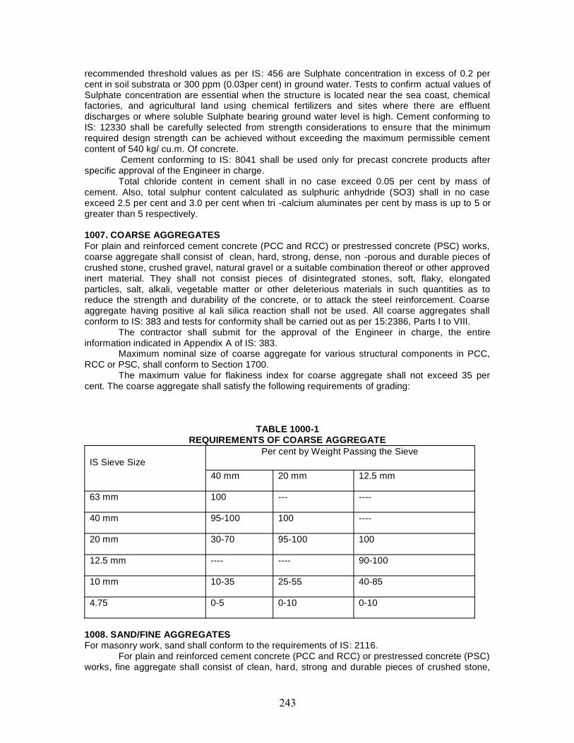
recommended threshold values as per IS: 456 are Sulphate concentration in excess of 0.2 percent in soil substrata or 300 ppm (0.03per cent) in ground water. Tests to confirm actual values ofSulphate concentration are essential when the structure is located near the sea coast, chemicalfactories, and agricultural land using chemical fertilizers and sites where there are effluentdischarges or where soluble Sulphate bearing ground water level is high. Cement conforming toIS: 12330 shall be carefully selected from strength considerations to ensure that the minimumrequired design strength can be achieved without exceeding the maximum permissible cementcontent of 540 kg/ cu.m. Of concrete.
Cement conforming to IS: 8041 shall be used only for precast concrete products afterspecific approval of the Engineer in charge.
Total chloride content in cement shall in no case exceed 0.05 per cent by mass ofcement. Also, total sulphur content calculated as sulphuric anhydride (SO3) shall in no caseexceed 2.5 per cent and 3.0 per cent when tri -calcium aluminates per cent by mass is up to 5 orgreater than 5 respectively.
1007. COARSE AGGREGATESFor plain and reinforced cement concrete (PCC and RCC) or prestressed concrete (PSC) works,coarse aggregate shall consist of clean, hard, strong, dense, non -porous and durable pieces ofcrushed stone, crushed gravel, natural gravel or a suitable combination thereof or other approvedinert material. They shall not consist pieces of disintegrated stones, soft, flaky, elongatedparticles, salt, alkali, vegetable matter or other deleterious materials in such quantities as toreduce the strength and durability of the concrete, or to attack the steel reinforcement. Coarseaggregate having positive al kali silica reaction shall not be used. All coarse aggregates shallconform to IS: 383 and tests for conformity shall be carried out as per 15:2386, Parts I to VIII.
The contractor shall submit for the approval of the Engineer in charge, the entireinformation indicated in Appendix A of IS: 383.
Maximum nominal size of coarse aggregate for various structural components in PCC,RCC or PSC, shall conform to Section 1700.
The maximum value for flakiness index for coarse aggregate shall not exceed 35 percent. The coarse aggregate shall satisfy the following requirements of grading:
TABLE 1000-1REQUIREMENTS OF COARSE AGGREGATE
IS Sieve SizePer cent by Weight Passing the Sieve
40 mm 20 mm 12.5 mm
63 mm 100 --- ----
40 mm 95-100 100 ----
20 mm 30-70 95-100 100
12.5 mm ---- ---- 90-100
10 mm 10-35 25-55 40-85
4.75 0-5 0-10 0-10
1008. SAND/FINE AGGREGATESFor masonry work, sand shall conform to the requirements of IS: 2116.
For plain and reinforced cement concrete (PCC and RCC) or prestressed concrete (PSC)works, fine aggregate shall consist of clean, hard, strong and durable pieces of crushed stone,
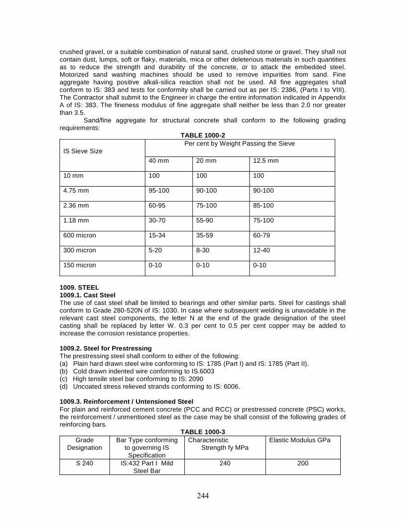
crushed gravel, or a suitable combination of natural sand, crushed stone or gravel. They shall notcontain dust, lumps, soft or flaky, materials, mica or other deleterious materials in such quantitiesas to reduce the strength and durability of the concrete, or to attack the embedded steel.Motorized sand washing machines should be used to remove impurities from sand. Fineaggregate having positive alkali-silica reaction shall not be used. All fine aggregates shallconform to IS: 383 and tests for conformity shall be carried out as per IS: 2386, (Parts I to VIII).The Contractor shall submit to the Engineer in charge the entire information indicated in AppendixA of IS: 383. The fineness modulus of fine aggregate shall neither be less than 2.0 nor greaterthan 3.5.
Sand/fine aggregate for structural concrete shall conform to the following gradingrequirements:
TABLE 1000-2
IS Sieve SizePer cent by Weight Passing the Sieve
40 mm 20 mm 12.5 mm
10 mm 100 100 100
4.75 mm 95-100 90-100 90-100
2.36 mm 60-95 75-100 85-100
1.18 mm 30-70 55-90 75-100
600 micron 15-34 35-59 60-79
300 micron 5-20 8-30 12-40
150 micron 0-10 0-10 0-10
1009. STEEL1009.1. Cast SteelThe use of cast steel shall be limited to bearings and other similar parts. Steel for castings shallconform to Grade 280-520N of IS: 1030. In case where subsequent welding is unavoidable in therelevant cast steel components, the letter N at the end of the grade designation of the steelcasting shall be replaced by letter W. 0.3 per cent to 0.5 per cent copper may be added toincrease the corrosion resistance properties.
1009.2. Steel for PrestressingThe prestressing steel shall conform to either of the following:(a) Plain hard drawn steel wire conforming to IS: 1785 (Part I) and IS: 1785 (Part II).(b) Cold drawn indented wire conforming to IS.6003(c) High tensile steel bar conforming to IS: 2090(d) Uncoated stress relieved strands conforming to IS: 6006.
1009.3. Reinforcement / Untensioned SteelFor plain and reinforced cement concrete (PCC and RCC) or prestressed concrete (PSC) works,the reinforcement / unmentioned steel as the case may be shall consist of the following grades ofreinforcing bars.
TABLE 1000-3Grade
DesignationBar Type conforming
to governing ISSpecification
CharacteristicStrength fy MPa
Elastic Modulus GPa
S 240 IS:432 Part I MildSteel Bar
240 200
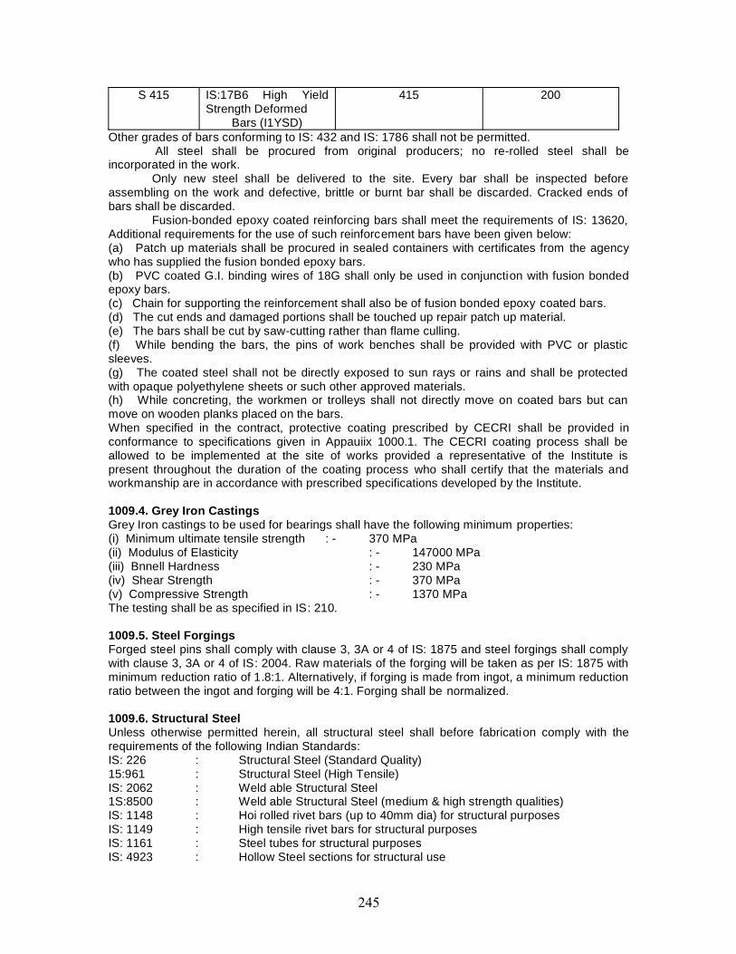
S 415 IS:17B6 High YieldStrength Deformed
Bars (I1YSD)
415 200
Other grades of bars conforming to IS: 432 and IS: 1786 shall not be permitted.All steel shall be procured from original producers; no re-rolled steel shall be
incorporated in the work.Only new steel shall be delivered to the site. Every bar shall be inspected before
assembling on the work and defective, brittle or burnt bar shall be discarded. Cracked ends ofbars shall be discarded.
Fusion-bonded epoxy coated reinforcing bars shall meet the requirements of IS: 13620,Additional requirements for the use of such reinforcement bars have been given below:(a) Patch up materials shall be procured in sealed containers with certificates from the agencywho has supplied the fusion bonded epoxy bars.(b) PVC coated G.I. binding wires of 18G shall only be used in conjunction with fusion bondedepoxy bars.(c) Chain for supporting the reinforcement shall also be of fusion bonded epoxy coated bars.(d) The cut ends and damaged portions shall be touched up repair patch up material.(e) The bars shall be cut by saw-cutting rather than flame culling.(f) While bending the bars, the pins of work benches shall be provided with PVC or plasticsleeves.(g) The coated steel shall not be directly exposed to sun rays or rains and shall be protectedwith opaque polyethylene sheets or such other approved materials.(h) While concreting, the workmen or trolleys shall not directly move on coated bars but canmove on wooden planks placed on the bars.When specified in the contract, protective coating prescribed by CECRI shall be provided inconformance to specifications given in Appauiix 1000.1. The CECRI coating process shall beallowed to be implemented at the site of works provided a representative of the Institute ispresent throughout the duration of the coating process who shall certify that the materials andworkmanship are in accordance with prescribed specifications developed by the Institute.
1009.4. Grey Iron CastingsGrey Iron castings to be used for bearings shall have the following minimum properties:(i) Minimum ultimate tensile strength : - 370 MPa(ii) Modulus of Elasticity : - 147000 MPa(iii) Bnnell Hardness : - 230 MPa(iv) Shear Strength : - 370 MPa(v) Compressive Strength : - 1370 MPaThe testing shall be as specified in IS: 210.
1009.5. Steel ForgingsForged steel pins shall comply with clause 3, 3A or 4 of IS: 1875 and steel forgings shall complywith clause 3, 3A or 4 of IS: 2004. Raw materials of the forging will be taken as per IS: 1875 withminimum reduction ratio of 1.8:1. Alternatively, if forging is made from ingot, a minimum reductionratio between the ingot and forging will be 4:1. Forging shall be normalized.
1009.6. Structural SteelUnless otherwise permitted herein, all structural steel shall before fabrication comply with therequirements of the following Indian Standards:IS: 226 : Structural Steel (Standard Quality)15:961 : Structural Steel (High Tensile)IS: 2062 : Weld able Structural Steel1S:8500 : Weld able Structural Steel (medium & high strength qualities)IS: 1148 : Hoi rolled rivet bars (up to 40mm dia) for structural purposesIS: 1149 : High tensile rivet bars for structural purposesIS: 1161 : Steel tubes for structural purposesIS: 4923 : Hollow Steel sections for structural use
IS: 11587 : Structural weather resistant steelIS: 808 : Specifications for Rolled Steel Beam, Channel and Angle SectionsIS: 1239 : Mild Steel TubesIS: 1730 : Dimension for Steel Plate, sheet and strip for structural and general
Engineer in chargeing purposesIS: 1731 : Dimension for Steel flats for structural and general Engineer in chargeing
purposesIS: 1732 : Dimension for round and square steel bars for structural and
general Engineer in chargeing purposesIS: 1852 : Rolling and cutting tolerances for hot rolled steel products the use
of structural steel not covered by the above standards may be permittedwith the specific approval of the authority. Refer to Section 1900 forfurther details.
1009.7. Stainless SteelStainless steel shall be austenitic chromium-nickel steel, possessing rust, acid and heat resistantproperties conforming Lo IS:66Q3 and IS:6911. Mechanical properties/grade for such stainlesssteel shall be as specified by the accepting authority, but in no case be inferior to mild steel.Generally, stainless steel is available as per AIS1 grades. A1SI 304 which is equivalent to grade04Crl8NillO of IS: 6911 satisfies the requirements of mechanical properties of structural steel.Other grades of stainless steel for specific purposes may be provided as per specificrequirements. For application in adverse/ corrosive environment, stainless steel shall conform toA1SI 316L or 02G17 Ni Mo2 of 13:6911.
1010. WATERWater used for mixing and curing shall be clean and free from injurious amounts of oils, acids,alkalis, salts, sugar, organic materials or other substances that may be deleterious to concrete orsteel. Potable water is generally considered satisfactory for mixing concrete. Mixing and curingwith sea water shall not be permitted. As a guide, the following concentrations represent themaximum permissible values:(a) To neutralize 200 ml sample of water using phenolpthalem as an indicator, it should notrequire more than 2 ml of 0.1 normal NaOH.(b) To neutralize 200 ml sample of water, using methyl orange as an indicator, it should notrequire more than 10 ml of 0.1 normal HCl.(c) The permissible limits for solids shall be as follows when tested in accordance with IS: 3025:
Permissible Limits (max)Organic 200 mg/litInorganic 3000 mg/litSulphate (SO4) 500 mg/litChlorides (Cl) 500 mg/litSuspended matter 2000 mg/lit* In case of structures of lengths 30m and below, the permissible limit of chlorides may be
increased up to 1000 mg/lit, all samples of water (including potable water) shall be tested andsuitable measures taken where necessary to ensure conformity of the water to the require mentsslated herein.(d) The pH value shall not be less than 6.
1011. TIMBERThe timber used for structural purposes shall conform lo IS: 883,
1012. CONCRETE ADMIXTURES1012.1. CentralAdmixtures arc materials added lo the concrete before or during mixing with a view to modify oneor more of the properties of concrete in the plastic or hardened state. Concrete admixtures areproprietary items of manufacture and shall be obtained only from established manufacturers withproven track record, quality assurance and full fledged laboratory facilities for the manufacture
and testing of concrete. The contractor shall provide the following information concerning eachadmixture after obtaining the same from the manufacturer:(a) Normal dosage and detrimental effects, if any, of tinder dosage and over dosage.(b) The chemical names of the main ingredients in the admixtures.(c) The chloride content, if any, expressed as a percentage by the weight of the admixture.(d) Values of dry material content, ash content and relative density of the admixture which canbe used for Uniformity Tests.(e) Whether or not the admixture leads to the entertainment of air when used as per themanufacturer’s recommended dosage, and if so to what extent.(f) Where two or more admixtures are proposed to he used in any one mix. Confirmation as totheir compatibility.(g) There would be no increase in risk of corrosion of the reinforcement or other embedment asa result of using the admixture.
1012.2. Physical and Chemical RequirementsAdmixtures shall conform to the requirements of IS: 9103. In addition, the following conditionsshall be satisfied:(a) "Plasticizers" and "Super-Plasticizers" shall meet the requirements indicated for "Waterreducing Admixture".(b) Except where resistance to freezing and thawing and to disruptive action of deicing salts isnecessary, the air content of freshly mixed concrete in accordance with the pressure methodgiven in IS: 1199 shall not be more than 2 per cent higher than that of the corresponding controlmix and in any case not more than 3 per cent of the test mix. (c) The chloride cement of theadmixture shall not exceed 0.2 per cent when tested in accordance with IS:6925. In addition, themaximum permissible limit of chloride content of all the constituents as indicated in Section 1700shall also be observed.(d) Uniformity tests on the admixtures are essential to compare qualitatively the composition ofdifferent samples taken from batch to batch or from the same batch at different times. The teststhat shall be performed along with permissible variations in the same are indicated below:- Dry Material Content: to be within 3 per cent and 5 per cent of liquid and solid admixturesrespectively of the value stated by the manufacturer.- Ash content: to be within 1 per cent of the value stated by the manufacturer.Relative Density (for liquid admixtures): to be within 2 per cent of the value stated by themanufacturer.(e) All tests relating to the concretes admixtures shall be conducted periodically at anindependent laboratory and compared with the data given by the manufacturer.
1013. REINFORCED CONCRETE PIPESReinforced concrete pipes for highway structures shall be of NP4 type conforming to therequirements of ARE: 458.
1014. STORAGE OF MATERIALS1014.1. GeneralAll materials may be stored at proper places so as to prevent their deterioration or intrusion byforeign matter and to ensure their satisfactory quality and fitness for the work. The storage spacemust also permit easy inspection, removal and restorage of the materials. All such materials eventhough stored in approved godowns/places, must be subjected to acceptance test prior to theirimmediate use.
1014.2. BrickBricks shall not be dumped at site. They shall be stacked in regular tiers as they are unloaded, tominimize breakage and defacement. The supply of bricks shall be available at site at any time.Bricks selected for use in different situations shall be stacked separately,
1014.3. Aggregates
Aggregate stockpiles may be made on ground that is denuded of vegetation, is hard and welldrained. If necessary, the ground shall be covered with 50 mm plank.
Coarse aggregates, unless otherwise agreed by the Engineer in charge in writing, shallbe delivered to the site in separate sizes (2 sizes when nominal size is 25 mm or less and 3 sizeswhen the nominal size is 32 mm or more). Aggregates placed directly on the ground shall not beremoved from the stockpile within 30 cm of the ground until the final cleaning up of the work, andthen only the clean aggregate will be permitted to be used.
In the case of fine aggregates, these shall be deposited at the mixing site not less than 8hours before use and shall have been tested and approved by the Engineer in charge.
1014.4. CementCement shall be transported, handled and stored on the site in such a manner as to avoiddeterioration or contamination. Cement shall be stored above ground level in perfectly dry andwater-tight sheds and shall be stacked not more than eight bags high. Wherever bulk storagecontainers are used their capacity should be sufficient to cater to the requirement at site andshould be cleaned at least once every 3 to 4 months.
Each consignment shall be stored separately so that it may be readily identified andinspected and cement shall be used in the sequence in which it is delivered at site. Anyconsignment or pan of a consignment of cement which had deteriorated in any way, duringstorage, shall not be used in the works and shall be removed from the site by the Contractorwithout charge to the Employer.
The Contractor shall prepare and maintain proper records on site in respect of delivery,handling, storage and use of cement and these records shall be available for inspection by theEngineer in charge at all times.
The Contractor shall make a monthly return to the Engineer in charge on the datecorresponding to the interim certificate date, showing the quantities of cement received andissued during the month and in stock at the end of the month.
1014.5. Reinforcement /Untensioned SteelThe reinforcement bars, when delivered on the job, shall be stored above the surface of theground upon platforms skids, or other supports, and shall be protected from mechanical injury"and from deterioration by exposure.
1014.6. Prestressing MaterialsAll prestressing steel, sheathing, anchorages and sleeves or coupling must be protected duringtransportation, handling and storage. The prestressing steel, sheathing and other accessoriesmust be stored under cover from rain or damp ground and protected from the ambientatmosphere if it is likely to be aggressive. Storage at site must be kept to the absolute minimum.
(a) Tendon: Wire, strand and bar from which tendons are to be fabricated shall be stored about300mm above the ground in a suitably covered and closed space so as to avoid direct climaticinfluences and lo protect them from splashes from my other materials and from the cuttingoperation of an oxy -acetylene torch or arc welding process in the vicinity. Under nocircumstances, tendon material shall be subjected lei any welding operation or on site healtreatment or metallic coaling such as galvanizing. Storage facilities and the procedures fortransporting material into or out of store shall be such that the material does not become kinkedor notched. Wire or strand shall be stored in large diameter coils which enable the tendons to belaid out straight. As a guide, for wires above 5mm dia, coils of about 2m dia without breaks orjoints shall be obtained from manufacturer and stored. Protective wrapping for tendons shall bechemically neutral. All prestressing steel must be provided with temporary protection duringstorage.
(b) Anchorage Components: The handling and storing procedures shall maintain theanchorage components in a condition in which they can subsequently perform their function to anadequate degree. Components shall be handled and stored so that mechanical damage anddetrimental corrosion are prevented. The corrosion of the gripping and securing system shall be
prevented. The use of correctly formulated oils and greases or of other corrosion preventingmaterial is recommended where prolonged storage is required. Such protective material shall beguaranteed by the producer to be non-aggressive and non-degrading.
Prestressing steel shall be stored in a closed store having single door with double lockingarrangements and no windows. Also the air inside the store shall be kept dry as far as possible byusing various means to the satisfaction of the Engineer in charge. Also instrument measuring theair humidity shall be installed inside the store. This is with a view to eliminating the possibility ofinitial rusting of prestressing steel during storage. The prestressing steel shall be coated withwater solvable-grease. The prestressing steel should be absolutely clean and without any signsof rust.
All prestressing steel shall be stored at least 30 cm above ground level and it shall beinvariably wrapped by protective cover of tar paper or polythene or any other approved material.
The Contractor should see that prestressing steel shall be used within 3 months of itsmanufacture. He should chalk out his programme in this respect precisely, so as to avoid initialcorrosion before placing in position.
1014.7. WaterWater shall be stored in containers/tanks covered at top and cleaned at regular intervals in orderto prevent intrusion by foreign matter or growth of organic matter. Water from shallow, muddy ormarshy surface shall not be permitted. The intake pipe shall be enclosed to exclude silt, mud,grass and other solid materials and there shall be a minimum depth of 0.60 m of water below theintake at all times.
1015. TESTS AND STANDARD OF ACCEPTANCEAll materials, even though stored in an approved manner shall be subjected to an acceptance testprior to their immediate use.
Independent testing of cement for every consignment shall be done by the Contractor atsite in the laboratory approved by the Engineer in charge before use. Any cement with lowerquality than those shown in manufacturer’s certificate shall be debarred from use. In case ofimported cement, the same series of tests shall be carried out before acceptance.
1015.1. Testing and Approval of MaterialThe Contractor shall furnish test certificates from the manufacturer/ supplier of materials
along with each batch of material(s) delivered to site.The Contractor shall set up a field laboratory with necessary equipment for testing of all
materials, finished products used in the construction as per requirements of conditions of contractand the relevant specifications. The testing of all the materials shall be carried out by theEngineer in charge or his representative for whom the Contractor shall make all the necessaryarrangements and bear the entire cost.
Tests which cannot be carried out in the field laboratory have to be got done at theContractor’s cost at any recognized laboratory / testing establishments approved by the Engineerin charge.
1015.2. Sampling of MaterialsSamples provided to the Engineer in charge or his representative for their retention is to
be in labeled boxes suitable for storage.Samples required for approval and testing must be supplied well in advance by at least
48 hours or minimum period required for carrying out relevant tests to allow for testing andapproval. Delay to works arising from the late submission of samples will not be acceptable as areason for delay in the completion of the works.
If materials are brought from abroad, the cost of sampling/testing whether in India orabroad shall be borne by the Contractor.
1015.3. Rejection of Materials not conforming to the Specifications

Any stack or batch of material(s) of which sample(s) does not conform to the prescribedtests and quality shall be rejected by the Engineer in charge or his representative and suchmaterials shall be removed from site by the Contractor at his own cost. Such rejected materialsshall not be made acceptable by any modifications.
1015.4. Testing and Approval of Plant and EquipmentAll plants and equipment used for preparing, testing and production of materials for
incorporation into the permanent works shall be in accordance with manufacturer’s specificationsand shall be got approved by the Engineer in charge before use.

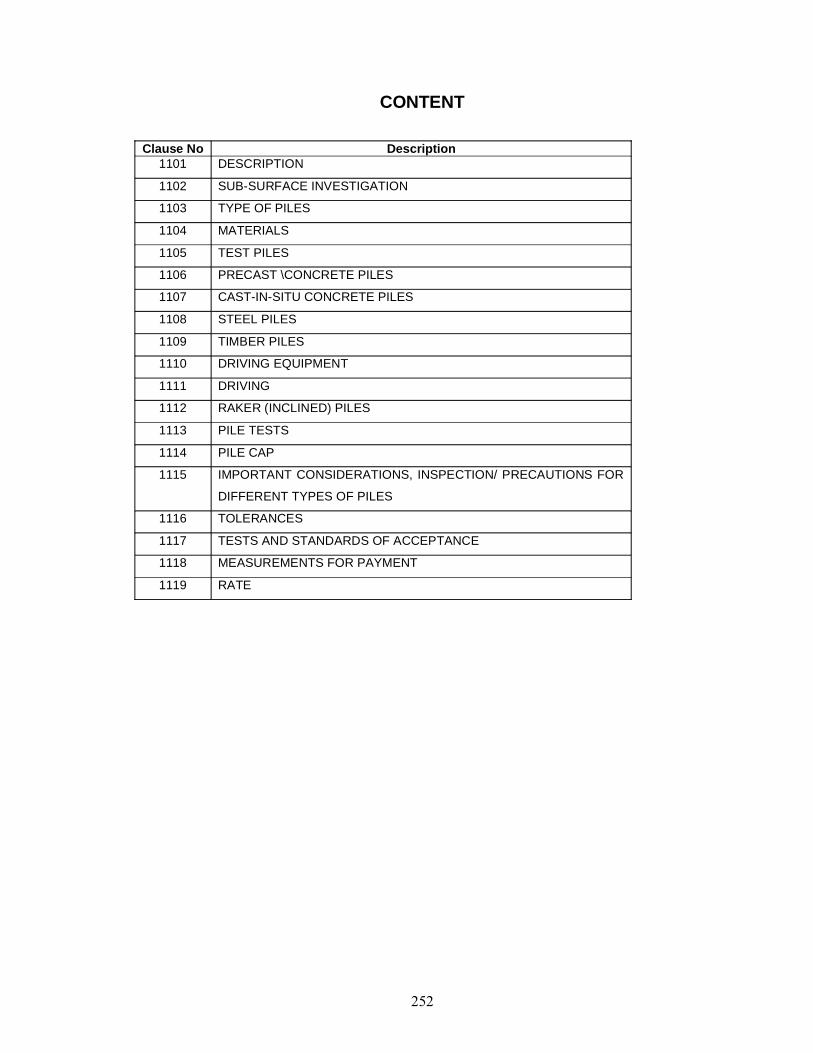
CONTENT
Clause No Description1101 DESCRIPTION
1102 SUB-SURFACE INVESTIGATION
1103 TYPE OF PILES
1104 MATERIALS
1105 TEST PILES
1106 PRECAST \CONCRETE PILES
1107 CAST-IN-SITU CONCRETE PILES
1108 STEEL PILES
1109 TIMBER PILES
1110 DRIVING EQUIPMENT
1111 DRIVING
1112 RAKER (INCLINED) PILES
1113 PILE TESTS
1114 PILE CAP
1115 IMPORTANT CONSIDERATIONS, INSPECTION/ PRECAUTIONS FOR
DIFFERENT TYPES OF PILES
1116 TOLERANCES
1117 TESTS AND STANDARDS OF ACCEPTANCE
1118 MEASUREMENTS FOR PAYMENT
1119 RATE
1101. DESCRIPTION
1101.1. This work shall consist of con struction of all types of piles for structures in accordance with thedetails shown on the drawings and conforming to the requirements of these specifications.
1101.2. The construction of pile foundations requires a careful choice of the piling system dependingupon sub-soil conditions and loading characteristics and type of structure. The permissible limits of totaland differential settlements, unsupported length of pile under scour, impact/entanglement of floatingbodies and any other special requirements of project are also equally important criteria for selection ofthe piling system. The method of installing the piles, including details of the equipment shall besubmitted by the Contractor and got approved from the Engineer.1101.3. The work shall be done as per IS:2911 except as modified herein.
1102. SUB-SURFACE INVESTIGATION1102.1. The complete sub-surface investigation of strata in which pile foundations are proposed shallbe carried out in advance and by in-situ pile tests. For details of geotechnical sub-surface explorationsreference may be made to Section 2400. At least one bore-hole for every foundation of the bridge shallbe executed. Borings should be carried upto sufficient depths so as to ascertain the nature of strataaround the pile shaft and below the pile tip. However, depth of boring shall not be less than :i) 1.5 times estimated length of pile in soil but not less than 15 m beyond the probable length of pileii) 15 times diameter of pile in weak/jointed rock but minimum 15 m in such rockiii) 4 times diameter of pile in sound, hard rock but minimum 3 m in such rock1102.2. The sub-surface investigation shall define adequately stratification of sub-strata including thenature and type of strata, its variation and extent and specific properties of the same. The investigationshall be adequate for the purpose of selection of appropriate piling system and for estimating designcapacities for different diameters and length of piles.1102.3. Pressure meter tests may be used in the case of rock, gravel or soil for direct evaluation of
strength and compressibility characteristic. Though these tests are of specialised nature they are mostappropriate for difficult/uncertain sub-strata especially for important projects.1102.4. For piles socketed into rocks, it is necessary to determine the uniaxial compressive strength ofthe rock and its quality.
The investigation shall also include location of ground water table and other parametersincluding results of chemical tests showing sulphate and chloride content and any other deleteriouschemical content in soil and/or ground water, likely to affect durability.1103. TYPE OF PILESThe piles may be of reinforced concrete, prestressed concrete, steel or timber. The piles may be ofsolid or hollow sections or steel cased piles filled with concrete. Concrete piles may be driven cast-in-situ or precast or bored cast- in-situ or precast piles driven into preformed bores. The shape of pilesmay be circular, square, hexagonal, octagonal, "H" or "I" Section.
1104. MATERIALS1104.1. The basic materials shall conform to the specifications for materials given in Section 1000. Thespecifications for steel reinforcement, structural concrete, prestressed concrete and structural steel tobe used in pile foundations shall be as given in the relevant sections.1104.2. Concrete in PilesGrade of concrete to be used in cast- in-situ piles shall not be less than M 20 and the cement contentshall not be less than 400 kg per cubic meter of concrete. Grades of concrete for precast reinforced andprestressed concrete piles shall not be less than M 25 and M 35 respectively. Maximum water cementratio shall be 0.5 for cast- in-situ piles and 0,45 for precast piles.
The minimum slump of concrete for driven cast- in-situ piles shall be 100 mm to 150 mm andthat of bored cast- in-situ piles 150 mm to 200 mm. The slump should not exceed 200 mm in any case.
Concrete mix should have homogeneous mixture with required workability for the system ofpiling adopted. Suitable and approved admixtures may be used in concrete mix where necessary.
Where piles are exposed to action of harmful chemicals or severe conditions of exposure dueto presence of sulphate, chloride etc, it may be preferable to opt for higher grades of concreterestricting water cement ratio to 0,45. Special types of cement, such as sulphate resistant cement may -be used where considered appropriate.
1105. TEST PILES1105.1. Test piles which are shown on the drawings or specified in the contract or installed by theContractor on his own to determine the lengths of piles lobe furnished shall conform to die requirementsfor piling as indicated in these specifications, if they are to be incorporated in the completed structure.
Test piles that are to become a part of the completed structure shall be installed with the sametype of equipment that is proposed to be used for piling in the actual structure.
Test piles which, are not to be incorporated in the completed structure shall be removed to atleast 600 mm below the proposed soffit level of pile cap and the remaining hole shall be backfilled withearth or other suitable material.
The piles shall be load tested in accordance with provisions laid down in this section.
1106. PRECAST \CONCRETE PILES1106.1. GeneralPrecast concrete piles shall be of the size and shape as shown in the approved drawings. If a squaresection is employed, die comers shall be chamfered at least 25 mm unless otherwise specified on diedrawings. The length of pile shall not normally exceed 25 metres. However, where special equipmentsfor. handling and installation are available to the satisfaction of the Engineer, longer length could bepermitted.
Piles shall be cast with a driving point and for hard driving, shall be shod with a metal shoeapproved by the Engineer.
1106.2. Stacking, Storing and HandlingCare shall be taken that at all stages of transporting, lifting and handling, piles are not damaged
or cracked. During transport and stacking of piles, they shall be supported at die same points as thoseprovided for lifting purposes. If the piles are put down temporarily during handling, they shall be placedon trestles or blocks located at the same points.
Piles shall be stored at least 300 mm above firm level ground which is not liable to unequalsubsidence or settlement under the weight of the stack of piles. They shall be placed on timbersupports which are level and spaced so as to avoid bending. The supports shall be vertically one abovethe other. Spaces shall be left round the piles to enable them to be lifted without difficulty. The order ofstacking shall be such that the older piles can be withdrawn without disturbing newer piles. Separatestacks shall be provided for different lengths of piles. Where piles are stacked in layers, the number oflayers shall not exceed three. Whenever curing is needed during storage, arrangements shall be madeto enable the piles to be watered. For detailed precautions with regard to curing operationsspecifications for structural concrete given in Section 1700 shall apply.
Before the operation of handling and driving the piles, the minimum periods counted from thetime of casting shall be allowed for as indicated in Table 1100-1. Prestressed piles shall not be lifted orhandled until fully stressed.
TABLE 1100-1 TIME FOR CURING PRECAST PILESType of cement used in
casting the pileMinimum periods from time of casting
Strike side-shutters(hours)
End of wetcuring(days)
Lift fromcasting bed
(days)
Drive(days)
Ordinary Portland 24 7 10 28Rapid hardening Portland 12 7 7 10
1106.3. Lengthening of PilesWhere a pile is to have another length cast on it during driving, the longitudinal reinforcement
shall preferably be joined by full penetration butt welding. The concrete at the top of the original pileshall be cut down to expose not less than 200 mm of the bars to avoid spalling of the concrete by heat.The added bars have to be held accurately and rigidly in position during welding. Where facilities on siteare insufficient to make proper butt welding practicable, the joint may be made by lapping. Thereinforcement at the head of pile will need to be exposed for full anchorage length or 600 mmwhichever is greater and the new bars over- lapped for this distance. Unless otherwise specified, theextension of the pile shall be formed to the same cross-sectional profile and with concrete of at least thesame strength as that specified for the original pile. The stirrup spacing shall in no case be greater than150 mm. Not more than one extension shall be permitted. In case more than one extension is permittedby the Engineer, only approved mechanical couplers shall be used.
Driving shall not be resumed until:
(i) The strength of the concrete in the extension is al least equal to the specified characteristicstrength of concrete in pile, and(ii) The approval of the Engineer has been obtained.
1106.4. Removal of Surplus LengthAny length of pile surplus to that required for incorporation in the structure shall be cut off neatly
and removed. During the process of cutting off, it shall be ensured that projecting reinforcement to beanchored into the pile cap and the prestressing strands/wires are not damaged. When strippingprestressed concrete piles, shock release of tendons shall be avoided. Reference may also be made toclause 7.7.1, of 15:2911 (Part I Section 3) in this connection.
1106.5. Risen PilesLevel reading should be taken on each pile after driving and again after all the piles are driven.
Piles which arc found to have risen due to ground heave or as a result of driving adjacent piles, shall bere-driven to the original depth or resistance unless re-driving tests on adjacent piles have shown this tobe unnecessary.1106.6. ManufactureThe pile should be cast in one continuous operation from end to end of each pile. Manufacture ofprecast concrete piles shall conform to the guidelines contained in clause Nos. 7.1,7.2 and 7.3 ofES:2911 (Part I, Section 3).
Pile shall be provided with suitable shoe for protecting the point of the pile during driving in hardground.
Piles shall not be moved from casting bed until the concrete has hardened sufficiently.Piles shall not be driven in less than 28 days after casting or unless their strength at the time of
driving is at least that specified for 28days.
1106.7. Prestressed Concrete PilesAdditional specifications for precast presticssed concrete piles shall conform to those contained
in clause 8 of IS:2911 (Part I Section 3).
1107. CAST-IN-SITU CONCRETE PILESCast-in-situ concrete piles may be either installed by making a bore into the ground by removal
of material or by driving a metal casing with a shoe at the tip and displacing the material laterally. Thetwo types of piles are termed as "bored piles" and "driven piles" respectively. Cast- in-situ concretepiles may be cast in metal shells which may remain permanently in place. However, other types of cast-in-situ concrete piles, plain or reinforced, cased or uncased, may be used if in the opinion of theEngineer the soil conditions permit their use and if their design and the methods of placing aresatisfactory.
The metal casing shall be of sufficient thickness and strength to hold its original form and showno harmful distortion after it and adjacent casings have been driven and the driving core, if any, hasbeen withdrawn.
Cast-in-situ concrete driven piles shall be installed using a properly designed detachable shoeat the bottom of the casing. Certain specific requirements of cast- in-situ driven piles shall be as perClauses 1110 and 1111.
Any liner or bore-hole which is improperly located or shows partial collapse that would affectthe load carrying capacity of the pile, shall be rejected or repaired as directed by the Engineer at thecost of the Contractor.
Wherever practicable, concrete should be placed in a clean dry hole. Where concrete is placedin. dry and there is casing present, the top 3 m of the pile shall be compacted using internal vibrators.The concrete should invariably be poured through a tremie with a funnel so that the flow is directed andconcrete can be deposited in the hole without segregation.
Where the casing is withdrawn from cohesive soils for the formation of cast- in-situ pile, theconcreting should be done with necessary precautions to minimise the softening of the soil by excesswater. Where mud flow conditions exist, the casing of cast-in-situ piles shall not be allowed to bewithdrawn.
Care shall be taken during concreting to prevent as far as possible the segregation of theingredients. The displacement or distortion of reinforcement during concreting and also while extractingthe tube shall be avoided.
If the concrete is placed inside precast concrete tubes or consists of precast sections, theseshall be free from cracks or other damage before being installed.
The concrete shall be properly graded, shall be self-compacting and shall not get mixed withsoil, excess water, or other extraneous matter. Special care shall be taken in silly clays and other soilswith the tendency to squeeze into the newly deposited concrete and cause necking. Sufficient head ofgreen concrete shall be maintained to prevent inflow of soil or water into the concrete.
The placing of concrete shall be a continuous process from the toe level to the top of the pile.To prevent segregation, a tube or tremie pipe as appropriate shall be used to pl ace concrete in allpiles.
To ensure compaction by hydraulic static heads, rate of placing concrete in the pile shaft shallnot be less than 6 m (length of pile) per hour.
Bored cast- in-situ piles in soils which arc stable, may often be installed with only a small casinglength at the top. A minimum of 2.0 m length of top of bore shall invariably be provided with casing toensure against loose soil falling into the bore. In cases in which the side soil can fall into the hole, it isnecessary to stabilise the side of the bore hole with drilling mud, or a suitable steel casing. The casingmay be left in position permanently specially in cases where the aggressive action of the ground wateris to be avoided, or in the cases of piles built in water or in cases where significant length of piles couldbe exposed due to scour.
For bored cast-in-situ piles, casing/liner shall be driven open ended with a pile driving hammercapable of achieving penetration of the liner to the length shown on the drawing or as approved by theEngineer. Materials inside the casing shall be removed progressively by air lift,grab or percussionequipment or other approved means.
Where bored cast- in-situ piles are used in soils liable to flow, the bottom of the casing shall bekept enough in advance of the boring tool to prevent the entry of soil into the casing, thus preventingthe formation of cavities and settlements in the adjoining ground. The water level in the casing shouldgenerally be maintained at the natural ground water level for the same reasons. The joints of the casingshall be made as tight as possible to minimise inflow of water or leakage of slurry during concreting.
Boring shall be carried out using rotary or percussion type equipment. Unless otherwiseapproved by the Engineer, the diameter of the bore-holes shall be not more than the inside diameter ofthe liner.
Prior to the lowering of the reinforcement cage into the pile shaft, the shaft shall be cleaned ofall loose materials. Cover to reinforcing steel shall be maintained by suitable spacers.
The diameter of the finished pile shall not be less than that specified and a continuous recordshall be kept by the Engineer as to the volume of concrete placed in relation to the pile length cast.
Before concreting under water, the bottom of the hole shall be cleaned of drilling mud and allsoft or loose material very carefully. In case a hole is bored with use of drilling mud, concreting shouldnot be taken up when the specific gravity of bottom slurry is more than 1.2. The drilling mud should bemaintained at 1.5m above the ground water level.
Concreting under water for cast-in-situ concrete piles may be done either with the use of tremiemethod or by the use of an approved method specially designed to permit under water placement ofconcrete.
General requirements and precautions for concreting under water are as follows :(a) The concreting of a pile must be completed in one continuous operation. Also, for bored holes, thefinishing of the bore, cleaning of (he bore, lowering of reinforcement cage and concreting of pile for fullheight must be accomplished in one continuous operation without any stoppage.(b) The concrete should be coherent, rich in cement with high slump and restricted water cement ratio.(c) The tremie pipe will have to be large enough with due regard to the size of aggregate. For 20 mmaggregate the tremie pipe should be of diameter not less than 150 mm and for larger aggregate, largerdiameter tremie pipes may be necessary.(d) The first charge of concrete should be placed with a sliding plug pushed down the tube ahead of itto prevent mixing of water and concrete.(e) The tremie pipe should always penetrate well into the concrete with an adequate margin of safelyagainst accidental withdrawal if the pipe is surged to discharge the concrete.(f) The pile should be concreted wholly by tremie and the method of deposition should not be changedpart way up the pile to prevent the laitance from being entrapped within the pile.(g) All tremie tubes should be scrupulously cleaned after use.
The minimum embedment of cast- in-situ concrete piles into pile cap shall be 150 mm. Anydefective concrete at the head of the completed pile shall be cut away and made good with newconcrete. The clear cover between the bottom reinforcement in pile cap from the top of the pile shall benot less than 25 mm. The reinforcement in the pile shall be exposed for full anchorage length to permitit to be adequately bonded into the pile cap. Exposing such length shall be done carefully to avoiddamaging the rest of the pile. In cases where the pile cap is to be laid on ground, a levelling course ofM 15 nominal mix concrete 100 mm thick shall be provided. Defective piles shall be removed or left in
place as judged convenient without affecting the performance of adjacent piles or pile cap. Additionalpiles shall be provided to replace the defective piles.
1108. STEEL PILESSteel piles shall be "H" or "I" sections as shown on the drawings and shall be of structural steel
conforming to the specifications given in Section 1000.Steel piles shall be protected by suitable anti -corrosive painting as specified on the drawing.
Piles shall be stored above the ground using protective packing to minimise damage to surface coating.Each pile shall be supplied preferably in one piece without splices.
At the option of the Contractor, steel piling consisting of structural steel plates welded togethermay be substituted for the rolled sections specified, provided that the depth, width and averagethicknesses are at least equal to those of the rolled sections, the steel plates conform to specificationgiven in Section 1000, the flanges are welded to the web with continuous fillet welds on either side ofthe web, and the welding conforms to Clause 1904.8 of these specifications.
The length of the steel pile may be built up in sections either before or during drivingoperations. The sections shall be of identical cross-section. Pile splices shall be made with fullpenetration butt welds over the whole cross-section. Pile splices shall develop at least the yield strengthof pile.
The connections shall be made by butt-welding the entire cross- section in accordance with theprovisions in Clause 1904.8 of these specifications. Care shall be taken to properly align the sectionsconnected so that the axis of the pile will be straight. The number of welded connections in the length ofpile shall be as few as possible.
The Engineer shall stamp each pile on the butt with a stamp which shall make an impressionthat is readily legible. Treated timber piles will be inspected by the Engineer after treatment.
Untreated limber may be used as test piles.Untreated timber piles and treated timber piles shall be of approved quality.Treated timber piles shall be driven within 6 months after treatment.
1109. TIMBER PILESTimber piles shall be furnished with tip protection and shall be protected by the use of steel
straps as hereinafter specified. Tip protection shall be suitable for use on timber piling of the size to bedriven. Details of lip protection shall be furnished to the Engineer for review and approval before drivingpiles. Not less than 2 separate steel straps shall be placed within 600 mm of the butt of each pile afterthe pile is square cut. Not less than 2 separate steel straps shall be placed within 300 mm of the tip ofeach pile. Additional intermediate steel straps shall be placed at not more than 3 metres centremeasured along the length of the pile.
Timber piles which are to be capped shall be separately cut off so that true bearing is obtainedon every pile. Piles inaccurately cut off shall be replaced. Splicing of timber piles shall not be permittedexcept by written permission of the Engineer.
1110. DRIVING EQUIPMENTPiles or their casings may be driven with any type of drop hammer, diesel hammer or single-
acting steam or compressed air hammer, provided they penetrate to the prescribed depth or attain thedesigned resistance without being damaged. The weight or power of the hammer should be sufficient toensure a penetration of at least 5 mm per blow, unless rock has been reached. It is always preferable toemploy the heaviest hammer practicable and to limit the stroke, so as not 10 damage the pile. Theminimum weight of the hammer shall be 2.5t. In the case of precast concrete piles the mass of thehammer shall be not less than 30 times the mass of 300 mm length of pile.
Steam or air hammers shall be furnished along with boiler or air compressor of capacity at leastequal to that specified by the manufacturer of the hammers. The boiler or air compressor shall beequipped with an accurate pressure gauge at all times. The valve mechanism and other parts of steam,air or diesel hammers shall be maintained in first class condition so that the length of stroke andnumber of blows per minute for which the hammer is designed, will be obtained. Inefficient steam, air ordiesel hammers shall be removed from the work.
1111. DRIVING1111.1. General Procedure
Details of the equipment and the method proposed for driving the piles shall be submitted withthe lender for scrutiny and approval of the Engineer. Piles shall be installed from firm ground or fromtemporary supports or from fixed platform. The arrangement shall provide sufficient rigidity to ensureaccuracy of pile driving under all conditions of tide, stream flow or hammer drop.
During driving the top of pile shall be protected by a suitable helmet of substantial - steelconstruction. The helmet shall provide uniform bearing across the top of the pile and shall hold the pilecentrally under the hammer. No pile shall be driven unless inspected and approved by the Engineer.
Piles shall be driven from a fixed frame of sufficient rigidity to ensure accuracy of driving withinspecified tolerances. Forces producing undue bending or torsional stresses in piles shall not be appliedduring driving. The force of the hammer shall be directed centrally and axially during driving.
The stroke of a single acting or drop hammer shall be limited to 1.2 m unless otherwisepermitted by the Engineer. A shorter stroke may be necessary when there is danger of damaging thepile.
Piles shall not be bent or sprung into position but shall be effectively guided and held on - lineduring the initial stages of driving. Attempts to correct any tendency for the pile to run off- line by theapplication of significant horizontal restraint will not be permitted. Shortly after the commencement ofdriving and at regular intervals throughout the driving operation, checks shall be made to ensure thatthe pile frame docs not exert any undue lateral force on the pile due to restraint within the helmet.
If the indications are that a pile will finish outside the specified tolerances, driving operations onthat pile will cease. The pile shall be withdrawn, the hole filled and the pile re-driven at no extra cost.
To avoid the possibility of premature "set-up" pile driving shall be continuous in the later stages,without any deliberate stops. (Delays of an hour or less may lead to significant "set-up" in piles i.e.resistance to further driving increases after driving is stopped).
If any pile is damaged in any way during driving, it shall be repaired or replaced as directed bythe Engineer, at no extra cost.
If during driving, the head of a pile is damaged to the extent that further driving is not possible,the head shall be cut off and driving continued. The cost of cutting off shall be borne by the Contractorand where, as a result of such cutting off the head, the pile is too short, the Contractor, shall, at his owncost, supply and splice on sufficient length of pile to restore the pile to its correct length.
Piles should be driven to the minimum acceptable penetration shown on the drawings. Thismay require preboring and/or jetting as indicated in these specifications with the full approval of theEngineer.
Piles shall be driven to nominal refusal or the required ultimate dynamic capacity nominated onthe drawings or until the top of the pile is at the level required and specified on the drawing whichevergives the lowest toe elevation. The Engineer’s decision in these mattersshall be final. Nominal refusal shall be taken as equivalent to 25 mm total penetration for the final 20blows using a hammer of driving energy as specified and shall be used as the criterion for acceptancefor piles founded on rock. Severe driving which results in an average set per blow less than 0.5 mm willnot be permitted.
Where hard drilling is encountered because of dense strata or obstructions located above thepredetermined pile tip level, nominal refusal shall not be considered to have been achieved unless theEngineer is satisfied that the total number of blows, as the average driving resistance specified fornominal refusal, indicates that further driving will not advance the pile through dense strata orobstructions.
The pile shall be driven as accurately as possible to the vertical or to specified batter. Strainingthe pile into position can damage it and the driving equipment should be adjusted as much as possibleto follow the position of the pile. Any deviation from the proper alignment shall be noted and promptlyreported to the Engineer. If the deviation is to such an extent that the resulting eccentricity cannot betaken care of by strengthening the pile cap or pile ties, such a pile shall, at the discretion of theEngineer, be replaced or supplemented by an additional pile. Unless otherwise specified, thepermissible positional deviation for piles shall be limited to those indicated in Clause1116.
Care shall be taken not to damage the pile by over-driving. Any sudden change in the rate ofpenetration which cannot be ascribed to the nature of the ground shall be noted and its causeascertained, if possible, before driving is continued.
When employing a tube which is subsequently withdrawn for the formation of cast- in-situ pile,consideration shall be given to the possibility of doing harm to a pile recently formed by driving the tubenearby before the concrete has sufficiently set. The danger of doing harm is greater in compact soilsthan loose soils. No pile shall be bored or driven within 3 m of a newly cast pile until at least 24 hoursafter completion of its installation.
Driving piles in loose sand tends to compact the sand which in turn increases the skin friction.Therefore, driving a number of friction piles in a group shall proceed outward from the centre asotherwise it will be difficult to drive the inner piles to the same depth as the others.
In the case of stiff clay also, the driving for a group of piles shall proceed outward from thecentre. However, in case of very soft soil, the driving may proceed from outside to inside, so that thesoil is restrained from flowing out during driving operations.
If there is a major variation between the depth at which adjacent foundation piles in a groupmeet refusal, a boring shall be made nearby to ascertain the cause of this difference. If the boringshows that the soil contains pockets of highly compressive material below the level of the shorter pile, itwill be necessary to enforce penetration of all the piles to a level below the bottom of the zone whichshows such pockets.1111.2. Preboring and Jetting
Driving of the piles may be assisted by preboring holes or by the use of jets or both subject tothe approval of the Engineer. These may be used essentially to achieve the minimum penetrationshown on the drawings where such penetration is not reached under normal conditions of drivingindicated in Clause 1111.1.
The diameter of the hole shall not be greater than the diagonal dimension of the pile less 100mm.
The maximum depth of the preboring shall be such that the specified set (or less) is obtainedwhen the toe of the pile is at founding level. Preboring shall be as approved by the Engineer and shallnot extend below one metre above the founding level and the pile shall be driven to at least one metrebelow the prebored hole. To ensure that the pile is properly supported laterally in the hole, any spaceremaining around the pile at the ground level after driving is finish d shall be backfilled with approvedgranular material.
When water jetting is used, at least two jets shall be attached to the pile symmetrically whenthis type of technique is used. The volume and pressure of water at the outlet nozzles shall be sufficientto freely erode material adjacent to the toe of the pile. The maximum depth of jetting shall be such thatthe specified set (or less) is obtained when the toe of the pile is at founding level. Jetting shall cease asdirect d by the Engineer and shall not proceed below one metre above the founding level and the pileshall be driven at least one metre below the pre-bored hole.
To avoid very hard driving and vibration in materials such as sand, jetting of piles by means ofwater may be carried out only by express permission of the Engineer and in’ such a manner as not toimpair the baring capacity of piles already in place, the stability of the soil o the safety of any adjoiningbuildings. Details of the arrangement for jetting shall be got approved from the Engineer in advance.
If, for jetting, large Quantities of water are used, it may be necessary to make provision forcollection of water when it comes to the ground surface, so that the stability of the piling plant is notendangered by the softening of the ground.
Jetting shall be stopped before completing the driving which shall always be finished byordinary methods. Jetting shall be stopped if there is any tendency for the pile tips to be drawn towardsthe pile already driven owing to the disturbance to the ground.
1112. RAKER (INCLINED) PILESThe maximum rake to be permitted in piles shall not exceed the following :
i) 1 in 8 [or large diameter cast-in-situ piles viz 0.75 m diameter and aboveii) I in 5 for smaller diameter cast-in-situ pilesiii) 1 in 4 for precast driven piles
1113. PILE TESTS1113.1. General
The bearing capacity of a single pile may be determined froth test loading a pile. The load teston a concrete pile may not be carried out earlier than 28 days from the time of casting of the pile.
There shall be two categories of tests on piles, namely, initial tests and routine tests. Initial testsshould be carried out on test piles which are not to be incorporated in the work. Routine tests shall becarried out as a check on working piles. The number of initial and routine tests on piles shall be asdetermined by the Engineer depending upon the number of foundations, span length, type ofsuperstructure and uncertainties of founding strata. In any case, the initial load tests shall not be lessthan 2 in number, while the routine load tests shall not be less than 2 per cent of the total number ofpiles in the structure nor less than 2 in number.
The above stipulations hold good for both vertical as well as lateral load tests on pilefoundations.
However, both initial and routine tests may be suitably increased for important structures orcases with large variation in the subsurface strata.
The methodology of carrying out load tests and of arriving at safe load on piles shall conform toIS-.29H (Part IV).
In case of any doubt of workmanship or load carrying capacity of working piles not subjected toroutine tests, or when ordered by the Engineer, or when provided in the contract, load tests on workingpiles may be supplemented by non-destructive testing. Such tests may include "Integrity Testing" of
concrete in the installed pile and utilisation of "Pile Driving Analyser" which gives an indication of pilecapacity in end bearing and side friction.
1114. PILE CAPPile Caps shall be of reinforced concrete. A minimum offset of 150 mm shall be provided
beyond the outer faces of the outer most piles in the group. If the pile cap is in contact with earth at thebottom, a levelling course of minimum 100 mm thickness of M 15 nominal mix concrete shall beprovided.
The attachment of the pile head to the cap shall be adequate for the transmission of loads andforces. A portion of pile top may be stripped of concrete and the reinforcement anchored into the cap.Manual chipping may be permitted after three days of pile casting, whilepneumatic tools for chipping shall not be used before seven days after pile casting. The top of pile afterstripping shall project at least 150 mm into the pile cap. A layer of surface reinforcement may beprovided with a cover of 25 mm to retain the integrity of concrete belowthe m in cap reinforcement which is to be laid 25 mm above the pile top.
Concreting of the pile cap shall be carried out in dry conditions. The bottom of the pile cap shallbe laid preferably as low as possible taking account of the water level prevalent at the time of casting.
The top of concrete in a pile shall be brought above cut-off level o permit removal of all laitanceand weak concrete before pile cap is laid. This will ensure good concrete at the cut-off level.
1115. IMPORTANT CONSIDERATIONS, INSPECTION/PRECAUTIONS FOR DIFFERENT TYPES OF PILES
1115.1. Driven Cast-in-Situ Piles1115.1.1. Specialist literature and the guidelines from the pile construction industry shall be consultedregarding the method of installation equipment and accessories for pile driving and recording of data.1 15.1.2. During installation of piles the final "set" of penetration of pile per blow of hammer shall bechecked taking an average of last 10 blows.1115.1.3. The pile shoes which may be of either cast iron conical type or mild steel flat type shall havedouble reams for proper seating of the removable casing tube inside the space between the reams.1115.1.4. Before commencement of pouring of concrete, it shall be ensured that there is no ingress ofwater in the casing tube from the bottom. Further adequate control during withdrawal of the casing tubeis essential so as to maintain sufficient head of concrete inside the casing tube at all stages ofwithdrawal.1115.1.5. Concrete in piles shall be cast upto a minimum height of 600 mm above the designed toplevel of pile, which shall be stripped off at the time of construction of pile cap.1115.2. Bored Cast-in-Situ Piles
1115.2.1. While concreting uncased piles, voids in concrete shall be avoided and sufficient head ofconcrete is to be maintained to prevent inflow of soil or water into the concrete. It is also necessary totake precautions during concreting to minimise the softening of the soil by excess water. Uncased cast-in-situ piles shall not be allowed where mudflow conditions exist.1115.2.2. The drilling mud such as bentonite suspension shall be maintained at a level sufficientlyabove the surrounding ground water level to ensure the stability of the strata which is being penetratedthroughout the boring process until the pile has been concreted.1115.2.3. Where bentonite suspension is used to maintain the stability of the bore-hole, it is essentialthat the properties of the material be carefully controlled at stages of mixing, supply to the bore-holeand immediately before concrete is placed. It is usual to limit :i) The density of bentonite suspension to 1.05 g/ccii) The marsh cone viscosity between 30 and 40iii) The pH value between 9.5 and 12iv) The silt content less than 1 per centv) The liquid limit of bentonite not less than 400 per cent
These aspects shall act as controlling factors for preventing contamination of bentonite slurryfor clay and silt.1115.2.4. The bores shall be washed by bentonite flushing to ensure clean bottom at two stages viz.after completion of boring and prior to concreting after placing of reinforcement cage. Flushing ofbentonite shall be done continuously with fresh bentonite slurry till the consistencyof inflowing and out- flowing slurry is similar.1115.2.5. Tremie of 150 mm to 200 mm diameter shall be used for concreting. The tremie should haveuniform and smooth cross-section inside, and shall be withdrawn slowly ensuring adequate height of

concrete outside the tremie pipe at all stages of withdrawal. Other recommendations for tremieconcreting are :(i) The sides of the bore-hole have to be stable throughout(ii) The tremie shall be water-tight throughout its length and have a hopper attached at its head by awater-tight connection(iii) The tremie pipe shall be large enough in relation to the size of aggregates. For 20 mm aggregatethe tremie pipe shall be of diameter not less than 150 mm and for larger size aggregate tremie pipe oflarger diameter is required.(iv) The tremie pipe shall be lowered to the bottom of the bore-hole, allowing water or drilling mud torise inside it before pouring concrete.(v) The tremie pipe shall always he kepi full of concrete and shall penetrate well into the concrete inthe bore-hole with adequate margin of safety against accidental withdrawal if the pipe is surged todischarge the concrete.1115.2.6. For very long or large diameter piles, use of retarding plasticiser in concrete is desirable.1115.2.7. For large diameter piles, it may be essential to conduct non-destuctive pile integrity tests toevaluate integrity of the pile.1115.2.8. Where possible, it may be desirable to grout the base of pile with cement slurry undersuitable pressure after concrete in the pile attains the desired strength. For this purpose, conduit pipeswith easily removable plugs at the bottom end should be placed in the borealong with reinforcement cage before concreting.
1116. TOLERANCES1116.l. Permissible Tolerances for Pilei) Precast Concrete Piles :
a) Variation in cross- sectional dimensions : ± 5 mmb) Variation in length : ± 25 mmc) Surface irregularities measured
with 3 m straight edge : 5 mmd) Bow for length in mm Pile Length
in mm1000
ii) Driven Pilesa) Variation in cross- sectional dimensions : +50 mm, -10 mmb) Variation from vertical or specified rake : 1 in 50c) Variation in the final position
of the head in plan : 75 mmd) Variation of level of top of piles : ± 25 mm
iii) Bored Pilesa) Variation in cross- sectional dimensions : + 50mm, -10mmb) Variation from vertical or specified rake : 1 in 50c) Variation in the Final position : 50 mm
of the head in pland) Variation of level of top of piles : ± 25 mm
1116.2. Permissible Tolerances for Pile Caps(a) Variation in dimensions : ± 50mm - 10mm(b) Misplacement from specified position in plan : 15 mm(c) Surface irregularities measured with 3 m straight edge : 5 mm(d) Variation of levels at the top : ± 25 mm
1117. TESTS AND STANDARDS OF ACCEPTANCE
The materials shall-be tested in accordance with these Specifications and shall meet theprescribed criteria.
The work shall conform to these Specifications and shall meet the prescribed standards ofacceptance.
1118. MEASUREMENTS FOR PAYMENTFor supply of precast concrete, timber or steel piles of specified cross-section, the
measurement shall be in metres of the length of piles ordered in writing by the Engineer measured from
the head to the butt of the shoe or the tapered point. Reinforcement in precast concrete piles shall notbe measured for payment.
For cast- in-situ driven and bored concrete piles of specified cross section, the measurementshall be the length in metres of the accepted pile that remains in the finished structure complete inplace. Reinforcement in cast- in-situ driven and bored concrete piles shall be measured for payment asper Section 1600.
Routine and Initial Pile Load Tests shall not be measured for payment.For installation of the pile, i.e. by driving in the case- of precast concrete, timber, steel and cast-
in-situ driven piles, and by boring in the case of cast- in-situ bored piles the measurement shall be thelength in metres that remains in the finished structure complete in place, limited to that shown ondrawings or ordered by the Engineer, No distinction shall be made for penetration through hard strata orrock and socketing into rock.
For steel liners/casing shown on the drawings to be permanently left in place, the measurementshall be by weight in tonnes that remains in the finished structure complete in place, limited to thatshown on drawings or ordered by the Engineer.
For the pile cap, the quantity of concrete shall be measured in cubic metres as per Section2700. While reinforcement in pile cap shall be measured in tonnes as per Section 1600.
1119. RATEThe contract unit rate for supplying precast concrete, timber or steel piles shall include cost of
all labour, materials, tools and equipment, and other work involved in making or fabricating the pilecomplete as shown on the drawing, and where required its loading, transport, delivery to site unloadingand stacking it at the place indicated by the Engineer. The cost of reinforcement as per Section 1600 inprecast concrete piles shall be deemed to be included in the quoted rate for supply of piles.
The contract unit rate for cast-m-situ driven and bored piles shall include the cost of concreteand all other items as per Section 1700. The contract unit rate shall also include costs of all labour,materials, equipments and all other incidentals involved in conducting routine and initial pile load testsincluding installation of piles for initial bad tests.
The contract unit rate for reinforcement in cast- in-situ driven arid bored piles shall be as perSection 1600.
The contract unit rate for installation of piles shall include full compensation for furnishing alllabour, materials, tools and equipment, and incidentals for doing all the works involved in driving timber,precast concrete and steel piles, driving or making bores for cast- in-situ driven and bored concretepiles, cutting off pile heads, all complete in place to the specified penetration of piles. Providingtemporary liner/casing and its withdrawal and placing reinforcement in position shall also be deemed tobe included in the rate for installation of pilesand no additional payment shall be made for the same.
The contract unit rate for permanent steel liners shall include cost of all labour, fabrication andplacing the steel liner to the required depth as shown on the drawings and as ordered by the Engineer,
The contract unit rate for concrete in pile cap shall cover all costs of labour, materials, tools,plant and equipment, formwork and staging including placing in position, sampling and testing andsupervision, all as per Section 1700. Reinforcement in the pile cap shall be paid for separately as per.Section 1600.

CONTENT
Clause No Description1201 DESCRIPTION
1202 GENERAL
1203 SETTING OUT AND PREPARATIONS FOR SINKING
1204 CUTTING EDGE
1205 WELL CURB
1206 WELL STEINING
1207 WELL SINKING
1208 BOTTOM PLUG
1209 SAND FILLING
1210 TOP PLUG
1211 WELL CAP
1212 TOLERANCES
1213 TESTS AND STANDARDS OF ACCEPTANCE
1214 MEASUREMENTS FOR PAYMENT
1215 RATE
1201. DESCRIPTIONThis work consists of construction of well foundation, taking it down to the founding level through allkinds of sub-strata, plugging the bottom, filling the inside of the well, plugging the top and providing awell cap in accordance with the details shown on the drawing and as per these specifications, or asdirected by the Engineer. In case of well foundations of size larger than 12 m diameter, supplementalconstruction specifications will be necessary.
1202. GENERAL1202.1. Wells may have a circular, rectangular, or D-shape in plan and may consist of one, two or morecomplements in plan. The outer wall of the well is known as well steining which may be cellular, Theprocess of taking down the well the founding level is known as well sinking. After reaching the foundinglevel, the hollow inside the well, ("dredge hole") is plugged at the bottom by concrete ("bottom plug").The dredge hole is then filled with approved filling upto the level indicated on the drawings and providedwith a concrete plug ("top plug").
To facilitate sinking of well, steel cutting edge is fabricated and connected to a concrete wellcurb of required shape. On top of the well curb, adequate height of well steining is cast and the processof sinking is carried out. After a portion of the well has been sunk, another height of well steining is caston top of the previous section and further sinking carried out. This process is continued till the bottomlevel of the well reaches the founding level.
At the top of die well steining, an adequately designed "well cap" is laid which transmits theloads and forces from the sub-structure (piersor abutments) to the foundations.
1202.2. At least one bore-hole must be available/carried out in accordance with these specifications ateach well foundation location, prior to commencement of work. The depth of bore-holes should extendupto a depth equal to one and a half times the outer .diameter/least dimension of the well below theanticipated founding level. The results of soil exploration should be presented in accordance withclause 7.4 of IRC78. In case the well foundation is to rest on a rocky strata, it may be necessary toundertake additional borings /probings prior to commencement of work to ascertain the actual profileand the quality of the rocky strata, at the level at which the well has to be seated, etc.
1202.3. Blasting may have to be resorted to in order to facilitate sinking through difficult strata, such asboulders and rocks etc. In case blasting is anticipated, protective/strengthening measures specified inclause 710.6 (IV) of IRC:78 shall be taken. The grade of concrete in bottom 3 metres of steining shallnot be leaner than M 20 or as shown on the drawings.
1202.4. In case the bore hole data shows the presence of steeply dipping rock, chiselling may have tobe resorted to so as to obtain proper seating of the foundation. For this purpose, the well may require tobe. dewatered completely under high air pressure inside the well. This process is known as pneumaticsinking. Pneumatic sinking may also have to be resorted to in cases where obstacles such as treetrunks, large sized boulders or hard strata etc. cannot be removed by open dredging. The necessity ofadopting pneumatic sinking shall be decided by the Engineer.
The curb and steining, have to be specifically designed for special loading when pneumaticsinking is adopted.
1203. SETTING OUT AND PREPARATIONS FOR SINKING1203.1. Necessary reference points shall be fixed, away from the zone of blow-ups or possiblesettlements resulting from well sinking operations. Such reference points shall be connected to thepermanent theodolite stations with the base line on the banks. The centre of the individual wells shallbe marked with reference to these stations. The distance, wherever practicable, shall be checked withthe help of accurate tapes and precision distomat.
Reference points shall also be fixed to mark X-X axis (usually traffic direction) and Y-Y axis(normal to X-X axis) accurately.
A temporary bench mark shall also be established near the well foundation, away from thezones of blow-ups or possible settlement. The bench mark shall be checked regularly with respect tothe permanent bench mark established at the bridge site.
1203.2. For wells which are to be pitched in water, an earthen or sand island shall be constructed. Sandislands are practicable for water depths of about 5 metres under stable bed soil conditions. For greaterdepths or in fast flowing rivers or for locations where soil is too weak to sustain sand island, floatingcaissons may have to be adopted.
The plan dimensions of sand islands shall be such as to have a working space of at least 2metres all around the steining. The dimension of the sand islands shall however be not less than twicethe dimension in plan of the well or caisson. Sand islands shall be maintained to perform their functions,until the well is sunk to a depth below the bed level at least equal to the depth of water.
Sand island shall be protected against scour and the top level shall be sufficiently above theprevailing water level to be decided by the Engineer so that it is safe against wave action.
While sand islands are constructed at well location, floating caissons are generally fabricated ator near the banks on dry land or dry docks. Floating caissons are towed into position in floatingcondition.
Floating caissons may be of steel, reinforced concrete or a combination of the two. They shouldhave at least 1.5 m free board above water level and increased, if considered necessary, in case thereis a possibility of caissons sinking suddenly owing to reasons such as scour likely to result from thelowering of caissons, effect of waves, sinking in very soft strata etc.
Stability of floating caissons shall be ensured against overturning and capsizing while beingtowed and during sinking for the action of water current, wave pressure, wind etc.
For floating caissons, a detailed method statement for fabrication, floating and sinking ofcaissons shall be prepared and furnished to the Engineer. Such statement shall include the totaltonnage of steel involved, fabrication and welding specifications, list of materials and plant and adescription of operations and manpower required for the work. The caisson shall be tested for leakagesbefore being towed to site.
1203.3. EquipmentEquipment shall be deployed for construction of well foundation as required and as directed by
the Engineer. Generally, the following equipments may be required for the work :(a) Crane with grab buckets - capacity 0,5 to 2.0 cum.(b) Submersible pumps(c) Air compressors, air locks and other accessories where pneumatic sinking of well
is anticipated.(d) Chisels of appropriate sizes(e) Aqua-header for culling rocky strata(f) Diving helmets and accessories(g) Equipment for concrete production, transportation planing and compaction.
1204. CUTTING EDGE1204.1. The mild steel cutting edge shall be made from structural steel sections. The cutting edge shallweigh not less than 40 kg per metre length and be properly anchored into the well curb, as shown in thedrawing.
When there are two or more compartments in a well, the bottom end of the cutting edge of theinner walls of such wells shall be kept at about 300 mm above that of outer walls.
1204.2. The parts of cutting edge shall be erected on level firm ground. Temporary supports shall beprovided to facilitate erection and maintaining the assembly in true shape. The fabrication may becarried out in the shop or at site. Steel sections shall not be heated and forced into shape. However, "V"cuts may be made in the horizontal portion, uniformly throughout the length, to facilitate cold bending.After bending, such "V" cuts should be closed by welding. Joints in the lengths of structural sections,unless otherwise specified shall be fillet welded using single cover plate to ensure the requisite strengthof the original section.
1204.3. The cutting edge shall be laid about 300 mm above prevalent water level.
1205. WELL CURB1205.1. The well curb may be precast or cast- in-situ. Steel formwork for well curb shall be fabricatedstrictly in conformity with the drawing. The outer face of the curb shall be vertical. Steel reinforcementsshall be assembled as shown on the drawings. The bottom ends of verticalbond rods of steining shall be fixed securely to the cutting edge with check nuts or by welds.
The formwork on outer face of curb may be removed within 24 hours after concreting. Theformwork ort inner face shall be removed after 72 hours.
1205.2. All concreting in the well curb shall be done in one continuous operation.
1206. WELL STEINING1206.1. The dimensions, shape, concrete strength and reinforcements of the well shall strictly conformto those shown on the drawings. The formwork shall preferably be of M.S. sheets shaped and stiffenedsuitably. In case timber forms are used, they shall be lined with plywoodor M.S. sheets.
1206.2. Steining built in the first lift above the well curb shall not be more than 2 metres and insubsequent lifts it shall not exceed the diameter of the well or the depth of well sunk below the adjoiningbed level at any time. For stability, the first lift of steining shall be cast only after sinking the curb at leastpartially for stability. Concreting of steining may be carried out in subsequent lifts of about 2 to 2.5metres. Attempts should be made to minimise the number of construction joints. The concreting layersshall be limited to about 450 mm restricting the free fall of concrete to not more than 1.5 m. Laitanceformed at the top surface of a lift shall be removed to expose coarse aggregates . before setting ofconcrete at the proposed construction joint. As far as possible, construction joints shall not be kept atthe location of laps in the vertical steining bars.
1206.3. The steining of the well shall be built in one straight line from bottom to top such that if the wellis tilted, the next lift of steining will be aligned in the direction of the tilt. The work will be checkedcarefully with the aid of straight edges of lengths approved by the Engineer. Plumb bob or spirit levelshall not be used for alignment. After sinking of a stage is complete, damaged portions if any of steiningat top of the previous stage shall be properly repaired before constructing the next stage.
1206.4. The height of steining shall be calibrated by making at lea 4 gauges (preferably in trafficdirection and in a direction normal to traffic direction) distributed equally on the outer periphery of thewell each in the form of a 100 mm wide strip painted on the well, with every metre mark shown in blackpaint. The gauges shall start with zero at the bottom of the cutting edge. Marking of the gauges shall bedone carefully with a steel tape.
1206.5. After reaching the founding level, the well steining shall be inspected to check for any damageor cracks. The Engineer will direct and the Contractor shall execute the remedial measures beforeacceptance of the well steining. In case the well cannot be accepted even with any remedial measures,then the well shall stand rejected.
1207. WELL SINKING1207.1. GeneralThe well shall as far as possible be sunk true and vertical through all types of strata.
Sinking or loading of the well with kentledge shall be commenced only after the steining hasbeen cured for at least 48 hours or as specified in the drawings.
No well shall be permitted to be placed in a pre-dredged hole.
The well shall be sunk by excavating material uniformly from inside the dredge hole. Use ofwater jetting, explosives and divert may be adopted for sinking of wells through difficult strata with priorapproval of the Engineer.
Normally dewatering of well should not be permitted as a means for sinking the well. It alsoshall never be resorted to if there is any danger of sand blowing under the well. Dewatering shallhowever be done when well is to be founded into rock. Pneumatic sinking may have to be resorted to
where obstacles such as tree trunks, large size boulders, etc. are met at the bottom or when there ishard strata which cannot be removed by open dredging. The necessity for pneumatic sinking shall bedecided by the Engineer.
Sinking history of well shall be maintained in the format given in Appendix 1200/1.
1207.2. Use of Kentledge as Sinking LoadKemedge shall be placed in an orderly and safe manner on the loading platform and in such a
way that it does not interfere with the excavation of the material from inside me dredge hole and alsodoes not in any way damage the steining of the well.
Where tilts are present or there is a danger of well developing a tilt, the position of the loadshall be regulated in such a manner as to provide greater sinking effort on the higher side of the well.1207.3. Use of Water Jetting
Water jetting may be employed for well sinking wherever necessary.
1207.4. Use of ExplosivesMild explosive charges may be used as an aid for sinking of the well only with prior permission
of the Engineer. Blasting of any sort shall only be done in the presence of the Engineer and not beforethe concrete in the steining has hardened sufficiently and is more than 7 days old. When likelihood ofblasting is predicted in advance, protection of the bottom portion of the well shall be done as per thesespecifications. After blasting operations are completed, the well curb and steining should be examinedfor any cracks and remedial measures taken.
If blasting has been used after the well has reached the design foundation level, normally 24hours shall be allowed to lapse before the bottom plug is laid.
The charges shall be exploded well below the cutting edge by making a sump so as to avoidchances of any damage to the curb or to the steining of the well. A minimum sump of 1 metre depthshould be made before resorting to blasting. Use of large charges, 0.7 kg or above, may not be allowedexcept under expert direction and with the permission from the Engineer. Suitable pattern of chargesmay be arranged with delay detonators to reduce the number of charges fired at a time. The burden ofthe charge may be limited to 1 metre and the spacing of holes may normally be kept as 0.5 to 0.6metres, All prevalent laws concerning handling, storing and using of explosives shall be strictlyfollowed.
All safety precautions shall be taken as per 1S:4081 "Safety Code for Blasting and relatedDrilling Operations", to the extent applicable, whenever blasting is resorted to.
There should be no equipment inside the well nor shall there be any labour in the close vicinityof the well at the time of exploding the charges.
If rock blasting is to be done for seating of the well, the damage caused by flying debris shouldbe minimised by covering blasting holes by rubber mats before blasting.
1207.5. Use of DiversUse of divers may be made both for sinking purpose like removal of obstructions, rock blasting
and for inspection. All safety precautions shall be taken as per any acceptable safety code for sinkingwith divers or any statutory regulations in force.
Only persons trained for the diving operation shall be employed and shall be certified to be fitfor diving by an approved doctor.
They shall work under expert supervision. The diving and other equipments shall be ofacceptable standard and certified to this effect by an approved independent agency. It shall be wellmaintained for safe use.
Arrangement for ample supply of low pressure clean cool air shall be ensured through anarmoured flexible hose pipe. Standby compressor plant shall be provided in case of Breakdown.
Separate high pressure connection for use of pneumatic tools shall be made. Electric lightswhere provided shall be at 50 volts (maximum). The raising of the diver from the bottom of wells shallbe controlled so that decompression rate conforms to the rate as laid down in appropriate regulations.
1207.6. Use of Pneumatic Sinking1207.6.1. General
The Engineer shall familiarise himself with particular reference to caisson diseases and workingof the medical air-lock. A doctor competent to deal with cases of "Caisson Diseases" or othercomplications arising as a result of working under high pressure, shall be stationed at the constructionsite when pneumatic sinking is under progress.
The contractor shall provide complete facilities including the issuing of orders to ensure strictenforcement of the requirements outlined in these specifications.
Safety provisions as contained in IS-.4138 and in these specifications shall be strictly followed.
Pneumatic sinking shall be restricted to a depth of 30.0 m.
1207.6.2. Man-Locks and ShaftsLocks, reducers, and shaft used in connection with caissons shall be of riveted construction
throughout. The material used in their manufacture shall be steel plate with thickness not less than 6mm.
Shafts shall be subjected to hydrostatic or air pressure test of at least 0.5 MPa, at whichpressure they shall be tight. The pressure at which testing has been done shall be clearly and visiblydisplayed.
Shafts shall be provided, with a safe, proper and suitable staircase for its entire length includinglanding platforms which are not more than 6 metres apart, Where this is impracticable due to spaceconstraint, suitable ladders along with landing platforms shall be installed. These shall be kept clear andin good condition at all times and shall be constructed, inspected and maintained to the entiresatisfaction of the Engineer.
A 1.0 m wide platform with 1,0 m high railing shall be provided all round the caisson air locks.
Where 15 or more men are employed, caissons shall have two locks, one of which shall beused as a man lock.
Locks shall be located so that the lowest pan of the bottom door shall not be less than 1 metreabove high water level.
The supply of fresh air to the working chamber shall at all times be sufficient to permit work tobe done without any danger or excessive discomfort. All air supply lines shall be supplied with checkvalves and carried as near to the face as practicable.
A man - lock shall be used solely for the compression or decompression of persons, and not forthe passage of plant and material and shall be maintained in a reasonably clean and sufficiently warmstate. However, any hand tool or hand instruments used for the purpose of the work may be carried intothe man - lock.
Where it is not reasonably practicable to provide a separate man - lock for use by persons only,the lock when it is in actual use for compression or decompression of a person or persons shall not beput, simultaneously, to any other use and shall be in a reasonably clean and sufficiently warm stale.
1207.6.3. ValvesExhaust valves shall be provided, having risers extending to the upper part of the chamber.
These shall be operated, whenever necessary specially after a blast. Precautions shall be taken thatmen are not allowed to resume work after a blast until the gas and smoke are cleared.
1207.6.4. Medical supervision and certification
Every employee absent from work for 10 or more consecutive days due to illness or any otherdisability shall be required to pass the regular physical examination by the doctor before beingpermitted to return to work.
After a person has been employed continuously in compressed air for a period of 2 months, heshall be re-examined by the doctor and shall not be permitted to work until such re-examination hasbeen made and the report is satisfactory.
No person known to be addicted to the excessive use of intoxicants shall be permitted to workin compressed air.
The doctor shall, at all times, keep a complete and full record of examinations made by him,which shall contain dates of examinations, a clear &;d full description of the person examined, his ageand physical condition at the time of examination and a statement as to the period such a person hasbeen engaged in such employment. Records shall be kept at the place where the work is in progressand shall be subject to inspection by authorised officers.
Every man lock shall always have a doctor or a responsible person in attendance. In case theperson in charge is not a doctor he must have positive means of promptly communicating with andsecuring the services of a competent doctor in case of emergency. Such arrangements shall invariablybe subject to the approval of the Engineer.
If the air pressure exceeds 0.2 MPa gauge or if 50 or more men are employed, it is obligatoryfor the person in charge of medical lock to be a doctor experienced in this type of work.
All cases of compressed-air illness shall be reported and copies of alt such reports shall bekept on file at the place of work.
1207.6.5, LightingAll lighting in compressed air chambers shall be operated only by electricity. Two independent
electric lighting systems with independent sources of supply shall be used. These shall be so arrangedthat the emergency source shall become automatically operative in case offailure of the regularly used source.
The minimum intensity of light on any walkway ladder, stairway, or lower working level shall beone-quarter (1/4) candlepower. In all work places, the lighting shall always be such as to enableworkmen to see their way about clearly. All external parts of lighting fixtures and electrical equipmentlying within 2.5 metres above the floor shall be constructed of non -combustible, non-absorbinginsulating materials. If metal is used it must be effectively earthed. Portable lamp shall havenoncombustible, non-absorbing insulating sockets, approved handles, basket guards and approvedcables. The use of worn or defective portable and pendant conductors, shall be prohibited.
1207.6.6. Safety against fire hazardNo oil, gasoline, or other combustible material shall be stored within 30 metres of any shaft,
caisson, or tunnel opening. However, oil may be stored in suitable tanks in isolated fireproof buildings,provided such buildings are not less than 15 metres from any shaft, caisson, or tunnel opening or anybuilding directly connected thereto.
Positive means shall be taken to prevent leaking flammable liquids from flowing into areasspecifically mentioned in the preceding paragraph.
Where feasible, a fire hose connected to a suitable source of water shall be provided at the topof every caisson. Where fire mains are not accessible, a supply of water shall be stored in tanks nearthe top of every caisson, provided fire pails or suitable pumps are kept available. Approved fireextinguishers shall also be provided.
1207.6.7. SanitationProperly heated, lighted and ventilated dressing rooms shall be provided for all employees
engaged in compressed air work. Such rooms shall contain lockers and benches and be open andaccessible to men during intermission between shifts. Adequate toilet accommodation of one for everytwenty five employees shall be provided.
Care shall be taken to keep all parts of the caissons and other working compartments, includinglocker rooms, dry rooms, rest rooms, and other equipment in a good sanitary condition and free fromrefuse, decaying, or other objectionable matter.
No nuisance shall be tolerated in the air chamber. Smoking shall be strictly prohibited and allmatches and smoking materials shall be left out of the locker rooms.
A separate dry-room shall be provided where working clothes may be dried within reasonabletime.
1207.6.8. Protection against gasesIn all cases where gas is expected including alluvium impregnated with decayed vegetable
matter the use of Davy Safety Lamp shall be compulsory.
1207.6.9. Additional safety provisionsa) The weight of the pneumatic platform and that of steining and kentledge, if any shall be sufficient toresist the uplift from air inside, skin friction being neglected in this case. If, at any section the totalweight acting downwards is less than the uplift pressure of air inside, additional kentledge shall beplaced on the well.
If it is not possible to make the well heavy enough during excavation, "blowing down" may beused. The men should be withdrawn and air pressure reduced. The well should then begin to move withsmall reduction in air pressure. "Blowing down" should only be used when the ground is such that it willnot heave up inside the chamber when the pressure is reduced. When the well does not move with thereduction in air pressure, kentledge should be added, "Blowing down" should be in short stages and thedrop should not exceed, 0.5 metre at any stage. To control sinking during blowing down, use ofpackings are recommended.b) The pneumatic sinking plant and other allied machinery shall not only be of proper design andmake, but also shall be worked by competent and well trained personnel. Every part of the machineryand its fixtures shall be minutely examined before installation and use. Availability of appropriatespares, standbys, safety of personnel as recommended in IS:4138 for working in compressed air mustbe ensured at site. Codes for safety and for working in compressed air and other labour laws andpractices prevalent in the country, as specified 10 provide safe, efficient and expeditious sinking shallbe followed.c) Inflammable materials shall not be taken into air locks and smoking shall be prohibited. Wherevergases are suspected to be issuing out of dredge hole, the same shall be analysed by trained personneland necessary precautions adopted to avoid hazard to life and equipment.d) Where blasting is resorted to, it shall be carefully controlled and all precautions regarding blastingshall be observed. Workers shall be allowed inside after blasting only when a competent and qualifiedperson has examined the chamber and steining thoroughly and found the same to be safe.
1207.7. Precautions During Sinkinga) When the wells have to be sunk close to each other and clear distance between them is not greaterthan the diameter of wells, sinking shall be taken up on all wells and they shall be sunk alternately sothat sinking of wells proceeds uniformly. Simultaneous and even dredging shall be carried OUL in thewells in such a manner that the difference in the levels of the sump and cutting edge in the adjacentwells does not exceed half the clear gap between them. Plugging of all the wells shall be done together.b) During sinking of dumb -bell or double D-shaped welts, the excavation in both the dredge holesshould be carried out simultaneously and equally.c) Bore chart shall be referred to constantly during sinking for taking adequate care while piercingdifferent types of strata. The type of soil as obtained during the well sinking should be compared withbore than so as to take prompt decisions.d) Before seasonal floods all wells on which sinking is in progress shall be sunk w sufficient depthsbelow the designed scour level. Further, they shall be temporarily filled and plugged so that they do notsuffer any tilt or shift during the floods.e) All necessary precaution; shall be taken against any possible damage to the foundations of existingstructures in the vicinity of the wells, prior to commencement of dredging from inside the well.f) The dredged material shall not be allowed to accumulate over the well. It shall be dumped andspread, as far away as possible, and then continuously and simultaneously removed, as directed by theEngineer. In case the river stream flows along one edge of the well being sunk, the dredged materialshall not be dumped on the dry side of the bank but on the side on which the river current flows.
g) Very deep sump shall not be made below the well curb, as it entails risk of jumping (sudden sinking)of the well. The depth of sump shall be generally limited to one-sixth of the outer diameter/least lateraldimension of the well in plan. Normally, the depth of sump shall not exceed 3.0 metres below the levelof the cutting edge unless otherwise specifically permitted by the Engineer.h) In case a well sinks suddenly with a jerk, the steining of the well shall be examined to thesatisfaction of the Engineer to see that no damage has occurred to it.i) In pneumatic sinking, the well shall not, at any time, be dropped to a depth greater than 500 mm bythe method of "blowing down".j) Dewatering shall be avoided if sand blows are expected. Any equipment and men working inside thewell shall be brought out of the well as soon as there are any indications of a sand-blow.k) Sand blowing in wells can often be minimised by keeping the level of water inside the well higherthan the water table and also by adding heavy kentledge.l) In soft strata prone to settlement/creep, the construction of the abutment wells shall be taken up onlyafter the approach embankment for a sufficient distance near the abutment has been completed.
1207.8. Tilts and ShiftsThe inclination of the well from the vertical is known as tilt and the horizontal displacement of
the centre of the well at the founding level from its theoretical position is known as shift.
Unless otherwise specified, the lilt of any well shall not exceed 1 (horizontal) in 80 (vertical),and the shift at the well base shall not be more than 150 mm in any resultant direction.
Tilts and shifts shall be carefully checked and recorded in the format vide Appendix 1200/Hregularly during sinking operations. For the purpose of measuring the tilts along the two axes of thebridge, reduced level of the marks painted on the surface of the steining of the well shall be taken. Fordetermination of shift, locations of the ends of the two diameters shall be precisely measured along thetwo axes, with reference to fixed reference points.
Whenever any tilt is noticed, adequate preventive measures like placing eccentric kentledge,pulling, strutting, anchoring or dredging unevenly and depositing dredge material unequally, pullingobstacles below cutting edge. Water jetting etc., shall be adopted before any further sinking. Aftercorrection, the dredged material shall be spread out uniformly.
A pair of wells close to each other have a tendency to come closer while sinking. Timber strutsmay be introduced in between the steining of these wells to prevent tilting.
Tilts occurring in a well during sinking in dipping rocky strata can be safeguarded by suitablysupporting the curb.
In the event of a well developing tilt or shift beyond the specified permissible values, theContractor shall have to carry out, at his own cost, suitable remedial measures to the satisfaction of theEngineer, to bring the till and shift within permissible values, as far as practicable.
If the resultant tilt and / or shift of any well exceeds the specified permissible values, generally itshould not exceed 1 in 50 and 300 mm respectively. The well so sunk shall be regarded as notconforming to specifications and a sub-standard work. The Engineer in his solediscretion, may consider accepting such a well, provided :(i) Calculations for foundation pressures and stiening stresses, accounting for the actual tilt and shiftfurnished by the Contractor show that the well is safe, Any remedial measures required to bring thestresses within permissible values (such as increase in the dimension of the well cap, provision ofdummy weights on the well cap etc), shall he carried out by the Contractor without chiming for any extracost.(ii) The Contractor shall agree to reduction in rates in accordance with Clause 1215(g).
In case the Engineer, in his discretion, rejects the well, the Contractor shall dismantle therejected well to the extent directed by the Engineer and remove the debris. Further, the Contractorshall, at his own risk and expense complete the bridge with modified span arrangement acceptable tothe Engineer.
1207.9. Seating of Wells
The well shall be uniformly seated at the founding strata. It shall be ensured by lest borings thatthe properties of the soil encountered at the founding strata and upto a depth of one and a half timesthe well diameter is identical to that adopted in the design. The procedurefor test borings shall satisfy the provisions of these specifications. In case the soil encountered isinferior to that adopted in design, the well shall be re-designed by the Engineer adopting the soilproperties actually encountered and the founding level intimated to the Contractor, who shall carry outthe work.
In case of seating of wells in hard rocky strata, where the rock profile is steeply sloping,pneumatic methods of sinking may be adopted to seat the well evenly as directed by the Engineer. Thedecision of adopting pneumatic sinking shall be taken by the Engineer. The cutting edge may also beembedded for a suitable depth in the rocky strata, as decided by the Engineer keeping in view thequality of rock. As an additional measure of safety, the well shall be anchored to the rocky strata byanchor bars provided in the steining of the well, as shown on the drawing irrespective of the fact thattension develops or not at the base of the well under design loads. After the well has been evenlyseated on good hard rock, arrangements shall be made to facilitate proper inspection in dry and visibleconditions before the bottom plug is laid.
1208. BOTTOM PLUGFor bottom plug, the concrete mix shall be designed (in dry condition) to attain the concrete
strength as mentioned on the drawing and shall contain 10 per cent more cement than that required forthe same mix placed dry, to cater for underwater concreting. However, the total cement content shallnot be less than 363 kg/cu.m. of concrete with a slump in the range of 150 mm to 200 mm. Admixturesmay be added to the concrete to impart the required characteristics indicated herein.
Concrete for the bottom plug shall be laid by tremie pipe method. Tremie concrete when startedshall be continued without interruption for full concreting in the bottom plug. The concrete productionequipment and placement equipment should be sufficient to enable under water concreting withinstipulated time. Necessary standby equipment should be available for emergency situation.
Before commencing plugging, all loose material from the bottom of the well shall be removed.
Concreting shall be done in one continuous operation till the dredge hole is filled upto therequired height and thereafter sounding shall be taken upto ensure that the concrete has been laid tohe required height.
Least disturbance shall be caused to the water inside the welt while laying concrete in thebottom plug.
Concrete shall not be disturbed in any way for at least 14 days.
In order to check any rise in the lev el of the bottom plug soundings should be taken at theclose of concreting and once every day for the subsequent 3 days.
The soundness of the bottom plug may be tested by dewatering the well by 5 metres below thesurrounding water level and checking the rise of water. The rate of rise shall preferably be less than 10cms per hour. In case the rate is higher, suitable remedial measures as directed by the Engineer, shallbe taken by the Contractor at his own cost.
1209. SAND FILLINGSand filling shall commence after a period of 3 days of laying of bottom plug. Also, the height of
the bottom plug shall be verified before starling sand filling.
Sand shall be clean and free from earth, clay clods, roots, boulders, shingles, etc. and shall becompacted as directed. Sand filling shall be carried out upto the level shown on the drawing, or asdirected by the Engineer,
1210. TOP PLUGAfter filling sand upto the required level a plug of concrete shall be provided over it as shown on
the drawing, or as directed by the Engineer.
1211. WELL CAPA reinforced cement concrete well cap will be provided over the lop of the steining in
accordance with the drawing. Formwork will be prepared conforming to the shape of well cap.Concreting shall be carried out in dry condition. A properly designed false steining may be providedwhere possible to ensure that the well cap is laid in dry conditions.
The bottom of the well cap shall be laid preferably as low as possible,iaking account the waterlevel prevalent at the lime of casting.
Bond rods of steining shall be anchored into the well cap.
1212. TOLERANCESThe permissible lilt and shift shall not exceed 1 (horizontal) in 80 (vertical) and the shift at the
well base shall not be more than 150 mm in any resultant direction.
For the well steining and well cap the permissible tolerances shall be as follows :a) Variation in dimension : +50 mm - 10 mmb) Misplacement from specified position in plan : 15 mmc) Surface irregularities measured with 3 m straight edge : 5 mmd) Variation of levels at the top : ±25 mm
1213. TESTS AND STANDARDS OF ACCEPTANCEThe materials shall be tested in accordance with these Specifications and shall meet the
prescribed criteria.
The work shall conform to these Specifications and shall meet the prescribed standards ofacceptance.
1214. MEASUREMENTS FOR PAYMENTAll quantities shall be measured from the drawing, or as ordered by the Engineer, excepting
those required to be provided by the Contractor at his cost.a) The culling edge shall be measured in tonnes based on the net weight of metal used in it, as perSection 1900.b) The concrete in curb, well steining and well cap shall be measured in cubic metres in each of theitems as per Section 1700, The reinforcements shall be measured in tonnes separately in each of theitems, as per Section 1600.c) The measurement for welt sinking shall be made in running metres for different depths and indifferent types of strata (for example, predominantly sand/clay soil, soft rock, hard rock, etc) asspecified in the Contract. The depth of sinking shall be measured from the level specified in theContract. If no level has been specified in the Contract, sinking shall be measured from the low waterlevel or from the level at which the cutting edge was laid, whichever is higher.d) The quantity of concrete in bottom and top plug shall be measured in cubic metres as per Section1700.e) The quantity of sand filling shall be measured m cubic metres.f) Pneumatic sinking, where required shall be paid as a separate item and shall be measured in cubicmetres of material to be excavated.
1215. RATEa) The Contract unit rates of culling edge shall cover all costs of labour, material, tools, plant andequipment, including placing in position, sampling and testing and. supervision, all as per respectiveSection of Structural Steel Work and as described in this section.b) The Contract unit rates for concrete in curb, steining, boltom plug, top plug and well cap, shall coverall costs of labour, material, toots, plant and equipment, formwork and staging including placing inposition, sampling and testing, and, supervision, all as per respective Section of Structural Concreteand as described in this section.c) The Contract unit rates for reinforcement in curb, steining, and well cap, shall cover all costs oflabour, material, tools, plant and equipment, including bending ID shape, placing in position, sampling,testing and supervision, all as per respective Section of Steel Reinforcement and as described in thissection.

d) The Contract unit rates for sand filling shall cover all costs of labour, material, tools, plant andequipment, including placing in position, sampling, testing and supervision, all as described in thissection.e) The Concrete unit rates for sinking shall cover the costs of labour, tools, and equipment and plantand for all operations and other incidentals for sinking of well including seating excepting provisions ofpneumatic sinking as described in this Section. The unit rates shall specify the strata such as types ofsoil, rock, etc. The rate shall cover all testing and supervision required for the work.f) The Contract unit rate of material to be excavated by pneumatic sinking shall cover all costs oflabour, material, tools, plant and other equipment and other incidentals and safety provisions andsupervision required for pneumatic sinking as per this Section.g) Reduction in contract unit rates for sinking as a penalty, in pursuance of clause 1207.8.
If any well with tilt and/or shift exceeding beyond permissible values is accepted by theEngineer, the Contractor shall give a reduction in the rates as follows :
S.No. Amount of tilt and/or shift Per cent deduction on therate(s) for sinking of whole well
1. Tilt exceeding the specified permissible value but equal toor within 1 in 60
5 per cent
2. Tilt exceeding 1 in 60 but equal to or within 1 in 50 10 per cent3. Tilt exceeding 1 in 50 20 per cent4. Shift exceeding the specified permissible value but equal to
or within 200mm2 per cent
5. Shift exceeding 200mm but equal to or within 300mm 5 per cent6. Shift exceeding 300 mm 10 per centPenalties for excessive tilt and shift shall be deducted separately.

1300- Brick Masonry

CONTENT
Clause No Description1301 DESCRIPTION1302 MATERIALS1303 PERSONNEL1304 CEMENT MORTAR1305 SOAKING OF BRICKS1306 JOINTS1307 LAYING1308 JOINTING OLD AND NEW WORK1309 CURING1310 SCAFFOLDING1311 EQUIPMENT1312 FINISHING OF SURFACES1313 ARCHITECTURAL COPING FOR WING/RETURN/
PARAPET WALL1314 ACCEPTANCE OF WORK1315 MEASUREMENTS FOR PAYMENT1316 RATE
1301. DESCRIPTIONThis work shall consist of construction of structures with bricks jointed togetherby cement mortar in accordance with the details shown on the drawings or asapproved by the Engineer.
1302. MATERIALSAll materials to be used in the work shall conform to the requirements laid downin Section 1000.
1303. PERSONNELOnly trained personnel shall be employed for construction and supervision.
1304. CEMENT MORTARCement and sand shall be mixed in specified proportions given in the drawings.Cement shall be proportioned by weight, taking the unit weight of cement as 1.44tonne per cubic metre. Sand shall be proportioned by volume taking into accountdue allowance for bulking. All mortar shall be mixed with a minimum quantity ofwater to produce desired workability consistent with maximum density of mortar.The mix shall be clean and free from injurious type of soil/acid/alkali/organicmatter or deleterious substances.
The mixing shall preferably be done in a mechanical mixer operatedmanually or by power. Hand mixing can be resorted to as long as uniform densityof the mix and its strength are assured subject to prior approval of the Engineer.Where permitted, specific permission is to be given by the Engineer. Hand mixingoperation shall be carried out on a clean water-tight platform, where cement andsand shall be first mixed dry in the required proportion by being turned over andover, backwards and forwards several times till the mixture is of uniform colour.Thereafter, minimum quantity of water shall be added to bring the mortar to theconsistency of a stiff paste. The mortar shall be mixed for at least two minutesafter addition of water.
Mortar shall be mixed only in such quantity as required for immediate use.The mix which has developed initial set shall not be used. Initial set of mortarwith ordinary Portland Cement shall normally be considered to have taken placein 30 minutes after mixing. In case the mortar has stiffened during initial settingtime because of evaporation of water, the same can be re-tempered by addingwater as frequently as needed to restore the requisite consistency, but thisretempering shall not be permitted after 30 minutes. Mortar unused for more than30 minutes shall be rejected and removed from site of work.
1305. SOAKING OF BRICKSAll bricks shall be thoroughly soaked in a tank filled with water for a minimumperiod of one hour prior to being laid. Soaked bricks shall be removed from thetank sufficiently in advance so that they are skin dry at the time of actual laying.
Such soaked bricks shall be stacked on a clean place where they are notcontaminated with dirt, earth, etc.
1306. JOINTSThe thickness of joints shall not exceed 10mm. All joints on exposed faces
shall be tooled to give concave finish.
1307. LAYINGAll brickwork shall be laid in an English bond, even and true to line, in
accordance with the drawing or as directed by the Engineer, plumb and level andall joints accurately kept. Half and cut bricks shall not be used except whennecessary to complete the bond. Closer in such cases shall be cut lo the requiredsize and used near the ends of the walls. The bricks used at the face and also atall angles forming the junction of any two walls shall be selected whole bricks ofuniform size, with true and rectangular faces.
All bricks shall be laid with frogs up on a full bed of mortar except in thecase of tile bricks. Each brick shall be properly bedded and set in position byslightly pressing while laying, so that the mortar gets into all their surface pores toensure proper adhesion. All head and side joints shall be completely filled byapplying sufficient mortar to brick already placed and on brick to be placed. Alljoints shall be properly flushed and packed with mortar so that no hollow spacesare left. No bats or cut bricks shall be used except to obtain dimensions of thedifferent courses for specified bonds or wherever a desired shape so requires.
The brick work shall be built in uniform layers, and for this purposewooden straight edge with graduations indicating thickness of each courseincluding joint shall be used. Comers and other advanced work shall be rakedback. Brickwork shall be done true to plumb or in specified batter. All coursesshall be laid truly horizontal and vertical joints shall be truly vertical. Vertical jointsin alternate courses shall come directly one over the other. During construction,no part of work shall rise more than one metre above the general constructionlevel, to avoid unequal settlement and improper jointing. Where this is notpossible in the opinion of the Engineer, the works shall be raked back accordingto the bond (and not toothed) at an angle not steeper than 45 degrees with priorapproval of the Engineer. Toothing may also be permitted where future extensionis contemplated.
Before laying bricks in foundation, the foundation slab shall be thoroughlyhacked, swept clean and wetted. A layer of mortar not less than 12 mm thickshall be spread on the surface of the foundation slab and the first course ofbricks shall be laid.
1308. JOINTING OLD AND NEW WORKWhere fresh masonry is to join with masonry that is partially/entirely set,
the exposed jointing surface of the set masonry shall be cleaned, roughened and
wetted, so as to effect the best possible bond with the new work. All loose bricksand mortar or other material shall be removed.
In the case of vertical or inclined joints, it shall be further ensured thatproper bond between the old and new masonry is obtained by interlocking thebricks. Any portion of the brickwork that has been completed shall remainundisturbed until thoroughly set.
In case of sharp corners specially in skew bridges, a flat cutback of 100mm shall be provided so as to have proper and bonded laying of bricks.
1309. CURINGGreen work shall be protected from rain by suitable covering and shall be
kept constantly moist on all faces for a minimum period of seven days. Brick workcarried out during the day shall be suitably marked indicating the date on whichthe work is done so as to keep a watch on the curing period. The top of themasonry work shall be left flooded with water at the close of the day. Wateringmay be done carefully so as not to disturb or wash out the green mortar.
During hot weather, ail Finished or partly completed work shall be coveredor wetted in such a manner as will prevent rapid drying of the brickwork.
During the period of curing of brick work, it shall be suitably protected fromall damages. At the close of day's work or for other period of cessation, wateringand curing shall have to be maintained. Should the mortar perish i.e. becomedry, white or powdery through neglect of curing, work shall be pulled down andrebuilt as directed by the Engineer. If any stains appear during watering, thesame shall be removed from the face.
1310. SCAFFOLDINGThe scaffolding shall be sound, strong and safe to withstand all loads
likely to come upon it. The holes which provide resting space for horizontalmembers shall not be left in masonry under one metre in width or immediatelynear the skew backs of arches. The holes left in the masonry work for supportingthe scaffolding shall be filled and ma-le good. Scaffolding shall be got approvedby the Engineer. However, the Contractor shall be responsible for its safety.
1311. EQUIPMENTAll tools and equipment used for mixing, transporting and laying of mortar
and bricks shall be clean and free from set mortar, dirt or other injurious foreignsubstances.
1312. FINISHING OF SURFACES1312.1. General
All brickwork shall be finished in a workmanlike manner with the thicknessof joints, manner of striking or tooling as described in these above specifications.
The surfaces can be finished by "jointing" or "pointing" or by "plastering"as given in the drawings.
For a surface which is to be subsequently plastered or pointed, the jointsshall be squarely raked out to a depth of 15 mm, while the mortar is still green.The raked joints shall be well brushed to remove dust and loose particles and thesurface shall be thoroughly washed with water, cleaned and wetted.
The mortar for finishing shall be prepared as per Clause 1304.
1312.2. JointingIn jointing, the face of the mortar shall be worked out while still green to
give a finished surface flush with the face of the brick work. The faces of brickwork shall be clean ed to remove any splashes of mortar during the course ofraising the brick work.
1312.3. PointingPointing shall be carried out using mortar not leaner than 1:3 by volume of
cement and sand or as shown on the drawing. The mortar shall be filled andpressed into the raked joints before giving the required finish. The pointing shallbe ruled type for which it shall, while still green, be ruled along the centre withhalf round tools of such width as may be specified by the Engineer. The superflush mortar shall then be taken off from the edges of the lines and the surface ofthe masonry shall be cleaned of all mortar. The work shall conform to IS:2212.
1312.4. PlasteringPlastering shall be done where shown on the drawing. Superficial
plastering may be done, if necessary, only in structures situated in fast flowingrivers or in severely aggressive environment.
Plastering shall be started from top and worked down. All putlog holesshall be properly filled in advance of the plastering while the scaffolding is beingtaken down. Wooden screeds 75 mm wide and of the thickness of the plastershall be fixed vertically 2.5 to 4 metres apart, to act as gauges and guides inapplying the plaster. The mortar hall be laid on the wall between the screedsusing the plaster's float and pressing the mortar so that the raked joints areproperly filled. The plaster shall then be finished off with a wooden straight edgereaching across the screeds. The straight edge shall be worked on the screedswith a small upward and sideways motion 50 mm to 75 mm at a time. Finally, thesurface shall be finished off with a plasterer's wooden float. Metal floats shall notbe used.
When recommencing the plastering beyond the work suspended earlier,the edges of the old plaster shall be scrapped, cleaned and welted before plasteris applied to the adjacent areas.

No portion of the surface shall be left unfinished for patching up a, a laterperiod.
The plaster shall be finished true to plumb surface and to the properdegree of smoothness as directed by the Engineer.
The average thickness of plaster shall not be less than the specifiedthickness. The minimum thickness over any portion of the surface shall not beless than the specified thickness by more than 3 mm.
Any cracks which appear in the surface and all portions which soundhollow when tapped, or are found to be soft or otherwise defective, shall be cut inrectangular shape and re-done as directed by the Engineer.
1312.5. Curing of FinishesCuring shall be commenced as soon as the mortar used for finishing has
hardened sufficiently not to be damaged during curing. It shall be kept wet for aperiod of at least 7 days. During this period, it shall be suitably protected from alldamages.
1312.6. Scaffolding for FinishesStage scaffolding shall be provided for the work. This shall be independent
of the structure.
1313. ARCHITECTURAL COPING FOR WING/RETURN/PARAPET WALLThis work shall consist of providing an Architectural coping for
wing/return/parapet walls.
The material used shall be cement mortar 1:3 or as shown on thedrawings prepared in accordance with Clause 1304.
The cement mortar shall be laid evenly to an average thickness of 15 mmto the full width of the top of the wall an d in continuation a band of 15 mmthickness and 150 mm depth shall be made out of the mortar along the top outerface of the walls.
1314. ACCEPTANCE OF WORKAll work shall be true to the lines and levels as indicated on the drawing or
as directed by the Engineer, subject to tolerances as indicated in thesespecifications.
Mortar cubes shall be tested in accordance with 15:2250 for compressivestrength, consistency of mortar and its water retentively. The frequency of testingshall be one sample for every 2 cubic metres of mortar, subject to a minimum 3samples for a day's work.

In case of plaster finish, the minimum surface thickness shall not be lessthan the specified thickness by more than 3mm.
1315. MEASUREMENTS FOR PAYMENTAll brick work shall be measured in cubic metres. Any extra work done by
the Contractor over the specified dimensions shall be ignored.
In arches, the length of arch shall be measured as the mean lengthbetween the extrados and intrados.
The work of plastering and pointing shall be measured in square metres ofthe surface treated.
Architectural coping shall be measured in linear metres.
1316. RATEThe contract unit rate for brick work shall include the cost of all labour,
materials, tools and plant, scaffolding and other expenses incidental to thesatisfactory completion of the work, sampling, testing and supervision asdescribed in these specifications and as shown on the drawings.
The contract unit rate for plastering shall include the cost of all labour,materials, tools and plant, scaffolding and all incidental expenses, sampling andtesting and supervision as described in these specifications.
The contract unit rate for pointing shall include erecting and removal ofscaffolding, all labour, material s, and equipment incidental to complete thepointing, raking out joints, cleaning, wetting, filling with mortar, trowelling; pointingand watering, sampling and testing and supervision as described in thesespecifications.
The contract unit rate for architectural coping shall include cost of alllabour, materials, tools and plant, sampling and testing and supervision asdescribed in these specifications.

1400 Stone Masonry

CONTENT
Clause No Description1401 DESCRIPTION
1402 MATERIALS
1403 PERSONNEL
1404 TYPE OF MASONRY
1405 CONSTRUCTION OPERATIONS
1406 ARCH1TEC URAL COPING FOR WING/RETURN/PARAPET WALLS
1407 TES S AND STANDARD OF ACCEPTANCE
1408 MEASUREMENTS FOR PAYMENT
1409 RATE
1401. DESCRIPTIONThis work shall consist of the construction of structures with stones jointed
together by cement mortar in accordance with the details shown on the drawings andthese specifications or as approved by the Engineer.
1402. MATERIALSAll materials used in stone masonry shall conform to Section 1000 except
cement mortar for stone masonry which shall conform to Clause 1304.
1403. PERSONNELOnly trained personnel shall be employed for construction and supervision.
1404. TYPE OF MASONRYThe type of masonry used for structures shall be random masonry (coursed or
uncoursed) or coursed rubble masonry (First sort). However, for bridge workgenerally, course rubble stone masonry shall be used. The actual type of masonryused for different parts of structures shall be specified on the drawings.
For facing work, ashlar masonry shall be used where indicated on thedrawings.
1405. CONSTRUCTION OPERATIONS1405.1. General Requirements
The dressing of stone shall be as specified for individual type masonry workand it shall also conform to the general requirements of IS:1597 and requirement fordressing of stone covered in IS:1129. Other specific requirements are coveredseparately with respect to particular types of rubble stone work.
1405.2. Laying1405.2.1. The masonry work shall be laid to lines, levels, curves and shapes asshown in the plan. The height in each course shall be kept same and every stone shallbe fine tooled on all beds joints and face full and true. The exposed faces shall begauged out, grooved, regulated and sunk or plain moulded as the case may be. Thefaces of each stone between the draft be left rough as the stone comes from quarryexcept where sacrificial layer is to be provided or plastering is resorted to due toaggressive environment.
1405.2.2. Stones shall be sufficiently wetted before laying to prevent absorption ofwater from mortar.
Stratified stones must be laid on their natural beds. AH bed joints shall benormal to the pressure upon them.
Stones in the hearting shall be laid on their broadest face that gives a betteropportunity to fill the spaces between stones.
The courses of the masonry shall ordinarily be pre-determined. They shallgenerally be of the same height. When there is to be variation in the height of courses,the larger courses are to be placed at lower levels, heights of courses decreasinggradually towards the top of the wall. The practice of placing loose mortar on thecourse and pouring water on it to fill the gaps in stones is not acceptable. Mortar may
be fluid mixed thoroughly and then poured in the joints. No dry or hollow space shallbe left anywhere in the masonry and each stone shall have all the embedded facescompletely covered with mortar.
In tapered walls, the beds of the stones and the planes of course should be atright angles to the batter. In case of bridge piers with batter on both sides, the courseshall be horizontal.
The bed which is to receive the stone shall be cleaned, wetted and coveredwith a layer of fresh mortar. All stones shall be laid full in mortar both in bed andvertical joints and settled carefully in place with a wooden mallet immediately onplacement and solidly embedded in mortar before it has set. Clean chips and spallsshall be wedged into the mortar joints and bed wherever necessary to avoid thickbeds or joints of mortar. When the foundation masonry is laid directly on rock, the facestones of the first course shall be dressed to fit into rock snugly when pressed down inthe mortar bedding over the rock. No dry or hollow space shall be left anywhere in themasonry and each stone shall have all the embedded faces completely covered withmortar. For masonry works over rock, a levelling course of 100 mm thickness and inconcrete M 15 shall be laid over rock and then stone masonry work shall be laidwithout foundation concrete block.
Face works and hearting shall be brought up evenly but the top of each courseshall not be levelled up by the use of flat chips.
For sharp corners specially in skew bridges, through stones shall be used inorder to avoid spalling of corners.
In case any stone already set in mortar is disturbed or the joints broken, it shallbe taken out without disturbing the adjoining stones and joints. Dry mortar and stonesthoroughly cleaned from the joints and stones and the stones reset in fresh mortar.Attempt must never be made to slide one stone on lop of another, freshly laid.
Shaping and dressing shall be done before the stone is laid in the work. Nodressing and hammering, which will loosen the masonry, will be allowed after it isonce placed. All necessary chases for joggles, dowels and clamps should be formedbefore hand.
Sufficient transverse bonds shall be provided by the u se of bond stoneextending from the front to the back of the wall and in case of thick wall from outsideto the interior and vice versa. In the latter case, bond stones shall overlap each otherin their arrangement.
In case headers are not available, precast headers of M15 concrete shall beused. Cast- in-situ headers are not permitted.
Stones shall break joint on the face for at least half the height of the course andthe bond shall be carefully maintained through-out.
In band work at all angle junctions of walls, the stones at each alternate courseshall be carried into each of the respective walls so as to unite the work thoroughly.
The practice of building up thin faces tied with occasional through stones andfilling up the middle with small stuff or even dry packing is not acceptable.
All quoins and the angles of the opening shall be made from selected stones,carefully squared and bedded and arranged to bond alternately long and short in bothdirections.
All vertical joints shall be truly vertical. Vertical joints shall be staggered as faras possible. Distance between the nearer vertical joints of upper layer and lower shallnot be less than half the height of the course.
Only rectangular shaped bond stones or headers shall be used. Bond stonesshall overlap each other by 150 mm or more.
All connected masonry in a structure shall be carried up nearly at one uniformlevel throughout but when breaks are unavoidable the masonry shall be raked insufficiently long steps to - facilitate jointing of old and new work. The stepping ofraking shall not be more than 45 degrees with the horizontal.
1405.3.1. Dressing : Stone shall be hammer dressed on the face, the sides and bedsto enable it to come in proximity with the neighbouring stone. The bushing on theexposed face shall not be more than 40 mm.
1405.3.2. Insertion of chips : Chips and spalls of stone may be used wherevernecessary to avoid thick mortar beds or joints and it shall be ensured that no hollowspaces are left anywhere in the masonry.
The chips shall not be used below hearting stones to bring these upto the levelof face stones. Use of chips shall be restricted to filling of interstices between theadjacent stones in h earting and they shall not exceed 20 per cent of the quantity ofstone masonry.
1405.3.3. Hearting stones : The hearting or interior filling of the wall face shall consistof rubble stones not less than 150 mm in any direction, carefully laid, hammered downwith a wooden mallet into position and solidly bedded in mortar. The hearting shouldbe laid nearly level with facing and backing.
1405.3.4. Bond stones : Through bond stones shall be provided in masonry upto 600mm thickness and in case of masonry above 600 mm thickness, a set of two or morebond stones overlapping each other at least by 150 mm shall be provided in a linefrom face to back.
In case of highly absorbent types of stones (porous limestone and sandstones,etc.,) the bond stone shall extend only about two-third into the wall, as through stonesin such cases may give rise to penetration of dampness and therefore, for allthicknesses of such masonry, a set of two or more bond stones overlapping eachother by at least 150mm shall be provided. One bond stone or a set of bond stonesshall be provided for every 0.50 sq. m. of the masonry surface.
1405.3.5. Quoin stone : Quoin stone i.e. stone specially selected and neatly dressedfor forming an external angle in masonry work, shall not be less than 0,03 cubic metrein volume.
1405.3.6. Plum stone : The plum stones are selected long stones embedded verticallyin the interior of the masonry to form a bond between successive courses and shall beprovided at about 900 mm intervals.
1405.3.7. Laying : The masonry shall be laid with or without courses as specified. Thequoins shall be laid header and stretcher alternately. Every stone shall be fitted to theadjacent stone so as to form neat and close joint. Face stone shall extend and bondwell in the back. These shall be arranged to break joints, as much as possible, and toavoid long vertical lines of joints.
1405.3.8. Joints : The face joints shall not be more than 20 mm thick, but shall besufficiently thick to prevent stone-to-stone contact and shall be completely filled withmortar.
1405.4. Square Rubble - Coursed Rubble (First Sort)1405.4.1. Dressing : Face stones shall be hammer dressed on all beds and joints soas to give them rectangular shape. These shall be square on all joints and beds. Thebed joints shall be chisel drafted for at least 80 mm back from the face and for at least40 mm for the side joints. No portion of the dressed surface shall show a depth of gapmore than 6 mm from the straight edge placed on it. The remaining unexposed portionof the stone shall not project beyond the surface of bed and side joints. Therequirements regarding bushing shall be the same as for random rubble masonry.
1405.4.2. Hearting stones : The hearting or interior filling of the wall face shall consistof flat bedded stone carefully laid, on prepared beds in mortar. The use of chips shallbe restricted to the filling of interstices between the adjacent stones in hearting andthese shall not exceed 10 per cent of the quantity of masonry. While using chips itshall be ensured that no hollow spaces are left anywhere in the masonry.
1405.4.3. Bond stones : The requirements regarding through or bond stone shall bethe same as for random rubble masonry, but these, shall be provided at 1.5 metre to1.8 metre apart clear in every course.
1405.4.4. Quoin stone : The quoins shall be of the same height of the course in whichthese occur and shall be formed of header stones not less than 450mm in length.They shall be laid lengthwise alternately along each face, square in their beds whichshall be fairly dressed to a depth of at least 100 mm.
1405.4.5. Face stone : Face stones shall tail into the work for not less than theirheights and at least one-third of the stones shall tail into the work for a length not lessthan twice their height. These shall be laid as headers and stretchers alternately.
1405.4.6. Laying : The stones shall be laid on horizontal courses and all vertical jointsshould be truly vertical. The quoin stones should be laid header and stretcheralternately and shall be laid square on their beds, which shall be rough chisel dressedto a depth of at least 100 mm.
1405.4.7. Joints : The face joints shall not be more than 10 mm thick, but shall besufficiently thick to prevent stone-to-stone contact and shall be completely filled withmortar.
1405.5. Ashlar Masonry (Plain Ashlar)1405.5.1. Dressing : Every stone shall b cut to the required size and shape, chiseldressed on all beds and joints so as to be free from all bushing. Dressed surface shallnot show a depth of gap of more than 3 mm from straight edge placed on it. Theexposed faces and joints, 6 mm from the face shall be fine tooled so that a straightedge can be laid along the face of th e stone in contact with e every point. All visibleangles and edges shall be true and square and free from chippings. The cornerstones (quoins) shall be dressed square and corner shall be straight and vertical.
1405.5.2. Bond stones : Through bond stones shall be provided in masonry upto 600mm thickness and in case of masonry above 600 mm thickness, a set of two or morebond stones overlapping each other at least by 150 mm shall be provided in a linefrom face to back. In case of highly absorbent types of stones (porous limestone andsandstones, etc.,) the bond stone shall extend only about two-third into the wall, asthrough stones in such cases may give rise to penetration of dampness and,therefore, for all thicknesses of such masonry a set of two or more bond stonesoverlapping each other by at least 150 mm shall be provided. One bond stone or a setof bond stones shall be 1.5 metres to 1.8 metres apart clear in every course.
1405.5.3. Laying : The face stone shall be laid header and stretcher alternately, theheader being arranged to come as nearly as possible in the middle of stretchersabove and below. Stones shall be laid in regular courses not less than 300 mm inheight and all courses of the same height unless otherwise specified. No stone shallbe less in width than its height or less in length than twice its height, unless otherwisespecified.
1405.5.4. Joints : All joints shall be full of mortar. These shall not be less than 3 mmthick. Face joints shall be uniform throughout, and a uniform recess of 20 mm depthfrom face shall be left with the help of a stone plate during the progress of work.
1405.6. PointingPointing shall be carried out using mortar not leaner than 1:3 by volume of
cement and sand or as shown on the drawing. The mortar shall be filled and pressedinto the raked out joints be ore giving the required finish. The pointing shall conform toClause 1312.3 of the specification. The work shall conform to IS:2212. The thicknessof joints shall no be less than 3 mm for Ashlar masonry. However, the maximumthickness of points in different works shall be as follows:
Random Rubble : 20 mmCoursed Rubble : 15 mmAshlar Mason : 5 mm
1405.7. CuringCuring shall conform to Clauses 1309 and 1312.5
1405.8. ScaffoldingFor scaffolding Clause 1310 shall apply.
1405.9. Wee HolesWeep holes shall conform to Clause 2706.
1405.10. Jointing with Existing StructuresFor Jointing with existing structures, the specifications given under Clause
1308 shall apply.
1406. ARCH1TEC URAL COPING FOR WING/RETURN/PARAPET WALLSArchitectural coping for wing/return/parapet walls shall conform to Clause 1313.
1407. TES S AND STANDARD OF ACCEPTANCEAll work shall be done to the tines and lines as indicated on he drawing or as
directed by the Engineer subject to tolerances as specified in these specifications.
Mortar cubes shall be taken in accordance with 15:2250 for compressivestrength, consistency of mortar and its water retentivity. The frequency of testing shallbe one sample for every two cubic metres of mortar subject to a minimum 3 samplesfor a day's work.
1408. MEASUREMENTS FOR PAYMENTStone masonry shall be measured in cubic metres.
In arches, the length of arch shall be measured as the mean length betweenthe extrados and intrados.
The work of pointing shall be measured in square metres.
Architectural coping shall be measured in linear metres.
1409. RATEThe contract unit rate for stone masonry shall include the cost of all labour,
materials, tools and plant, scaffolding, sampling and testing, supervision and otherexpenses incidental to the satisfactory completion of the work as described hereinabove.
The contract unit rate for pointing shall include erecting and removal ofscaffolding, all labour, materials and equipment incidental to complete pointing, rakingout joints, cleaning, wetting, filling with mortar, trowelling, pointing and watering,sampling and testing and supervision as described in these specifications.
The contract rate for architectural coping shall include the cost of all labour,materials, tools and plant, sampling and testing and supervision as described in thesespecifications.

1500 Formwork

CONTENT
Clause No Description1501 DESCRIPTION
1502 MATERIALS
1503 DESIGN OF FORMWORK
1504 WORKMANSHIP
1505 FORMED SURFACE AND FINISH
1506 PRECAUTIONS
1507 PREPARATION OF FORMWORK BEFORE CONCRETING
1508 REMOVAL OF FORMWORK
1509 RE-USE OF FORMWORK
1510 SPECIALISED FORMWORK
1511 TESTS AND STANDARDS OF ACCEPTANCE
1512 MEASUREMENTS FOR PAYMENT
1513 RATE
1501. DESCRIPTIONFormwork shall include all temporary or permanent forms required for forming the concrete of theshape, dimensions and surface finish as shown on the drawing or as directed by the Engineer, togetherwith all props, staging, centering, scaffolding and temporary construction required for their support. Thedesign, erection and removal of formwork shall conform to IRC:87 "Guidelines for Design and Erectionof False work for Road Bridges" and these specifications.
1502. MATERIALSAll materials shall comply with the requirements of IRC87. Materials and components used for
formwork shall be examined for damage or excessive deterioration before use / re-use and shall beused only if found suitable after necessary repairs. In case of timber formwork, the inspection shall notonly cover physical damages but also signs of attacks by decay, rot or insect attack or the developmentof splits.
Forms shall be constructed with metal or timber. The metal used for forms shall be of suchthickness that the forms remain true to shape. All bolts should be countersunk. The use of approvedinternal steel ties or steel or plastic spacers shall be permitted. Structural steel tubes used as supportfor forms shall have a minimum wall thickness of 4 mm. Other materials conforming to the requirementsof IRC:87 may also be used if approved by the Engineer.
1503. DESIGN OF FORMWORK1503.1. The Contractor shall furnish the design and drawing of complete formwork (i.e. the forms aswell as their supports) for approval of the Engineer before any erection is taken up. If proprietarysystem of formwork is used, the Contractor shall furnish detailed information as per Appendix 150011 tothe Engineer for approval.
Notwithstanding any approval or review of drawing and design by the Engineer, the Contractorshall be entirely responsible for the adequacy and safety for formwork.
1503.2. The design of the formwork shall conform to provisions of IRC:87. It shall ensure that the formscan be conveniently removed without disturbing the concrete. The design shall facilitate proper andsafe access to all parts of formwork for inspection.
1503.3. In the case of prestressed concrete superstructure, careful consideration shall be given toredistribution of loads on props due to prestressing.
1504. WORKMANSHIP1504.1. The formwork shall be robust and strong and the joints shall be leak-proof.
Balli shall not be used as staging. Staging must have cross bracings and diagonal bracings inboth directions. Staging shall be provided with an appropriately designed base plate resting on firmstrata.
1504.2. The number of joints in the formwork shall be kept to a minimum by using large size panels.The design shall provide for proper "soldiers" to facilitate alignment. All joints shall be leak proof andmust be properly sealed. Use of PVC JOINT sealing tapes, foam rubber or PVC T-section is essentialto prevent leakage of grout.1504.3. As far as practicable, clamps shall be used to hold the forms together. Where use of nails isunavoidable minimum number of nails shall be used and these shall be left projecting so that they canbe withdrawn easily. Use of double headed nails shall be preferred.
1504.4. Use of ties shall be restricted, as far as practicable. Wherever ties are used they shall be usedwith HOPE sheathing so that the ties can easily be removed. No parts prone to corrosion shall be leftprojecting or near the surface. The sheathing shall be grouted with cement mortar of the same strengthas that of the structure.
1504.5. Unless otherwise specified, or directed, chamfers or fillets of sizes 25 mm x 25 mm shall beprovided at all angles of the formwork to avoid sharp corners. The chamfers, bevelled edges andmouldings shall be made in the formwork itself. Opening for fixtures and other fittings shall be providedin the shuttering as directed by the Engineer.
1504.6. Shuttering for walls, sloping members and thin sections of considerable height shall beprovided with temporary openings to permit inspection and cleaning out before placing of concrete.
1504.7. The formwork shall be constructed with precamber to the soffit to allow for deflection of theformwork. Pre-camber to allow for deflection of formwork shall be in addition to that indicated for thepermanent structure in the drawings.
1504.8. Where centering trusses or launching trusses are adopted for casting of superstructure, thejoints of the centering trusses, whether welded, riveted or bolted should be thoroughly checkedperiodically. Also, various members of the centering trusses should be periodically examined for properalignment and unintended deformation before proceeding with the concreting. They shall also beperiodically checked for any deterioration in quality due to steel corrosion.
1504.9. The formwork shall be so made as to produce a finished concrete true to shape, line and levelsand dimensions as shown on the drawings, subject to the tolerances specified in respective sections ofthese specifications, or as directed by the Engineer.
1504.10. Where metal forms are used, all bolts and rivets shall be countersunk and well ground toprovide a smooth, plane surface. Where timber is used it shall be well seasoned, free from loose knots,projecting nails, splits or other defects that may mar the surface of concrete.
1504.11. Forms shall be made sufficiently rigid by the use of ties and bracings to prevent anydisplacement or sagging between supports. They shall be strong enough to withstand all pressure,ramming and vibration during and after placing the concrete. Screw jacks or hard wood wedges whererequired shall be provided to make up any settlement in the formwork either before or during the placingof concrete.
1504.12. The formwork shall take du e account of the calculated amount of positive or negative camberso as to ensure the correct final shape of the structures, having regard to the deformation of false work,scaffolding or propping and the instantaneous or deferred deformation due to variou s causes affectingprestressed structures.
1504.13. Suitable camber shall be provided to horizontal members of structure, specially in long spansto counteract the effects of deflection. The formwork shall be so fixed as to provide for such camber.
1504.14. The formwork shall be coaled with an approved release agent that will effectively preventsticking and will not stain the concrete surface. Lubricating (machine oils) shall be prohibited for use ascoating.
1505. FORMED SURFACE AND FINISHThe formwork shall be lined with material approved by the Engineer so as to provide a smooth
finish of uniform texture and appearance. This material shall leave no stain on the concrete and so fixedto its backing as not to impart any blemishes. It shall be of the same type and obtained from only onesource throughout for the construction of any one structure. The contractor shall make good anyimperfections in the resulting finish as required by the Engineer. Internal ties and embedded metal partsshall be carefully detailed and their use shall be subject to the approval of the Engineer.
1506. PRECAUTIONS(i) Special measures in the design of formwork shall be taken lo ensure that it does not hinder theshrinkage of concrete. The soffit of the formwork shall be so designed as to ensure that the formworkdoes not restrain the shortening and/or hogging of beams during prestressing. The forms may beremoved at the earliest opportunity subject to the minimum time for removal of forms with propsretained in position.(ii) Where necessary, formwork shall be so arranged that the soffit form, properly supported on propsonly can be retained in position for such period as may be required by maturing conditions.(iii) Any cut-outs or openings provided in any structural member LO facilitate erection of formwork shallbe closed with the same grade of concrete as the adjoining structure immediately after removal offormwork ensuring watertight joints.(iv) Provision shall be made for safe access on. to and about the formwork at the levels as required.(v) Close watch shall be maintained lo check for settlement of formwork during concreting. Anysettlement of formwork during concreting shall be promptly rectified.
(vi) Water used for curing should not be allowed to stagnate near the base plates supporting thestaging and should be properly drained.
1507. PREPARATION OF FORMWORK BEFORE CONCRETINGThe inside surfaces of forms shall, except in the case of permanent form work or where
otherwise agreed to by the Engineer be coated with a release agent supplied by approvedmanufacturer or of an approved material to prevent adhesion of concrete to the formwork.
Release agents shall be applied strictly in accordance with the manufacturer's instructions andshall not be allowed to come into contact with any reinforcement or prestressing tendons andanchorages. Different release agents shall not be used in formwork for exposed concrete.
Before re-use of forms, the following actions shall be taken:(i) The contact surfaces of the forms shall be cleaned carefully and dried before applying a releaseagent.(it) It should be ensured that the release agent is appropriate to the surface to be coaled. The sametype and make of release agent shall be used throughout on similar formwork materials and differenttypes should not be mixed.(iii) The form surfaces shall be evenly and thinly coaled with release agent. The vertical surface shallbe treated before horizontal surface and any excess wiped out.(iv) The release agent shall not come in contact with reinforcement or the hardened concrete.
All forms shall be thoroughly cleaned immediately before concreting.
The Contractor shall give the Engineer due notice before placing any concrete in the forms topermit him to inspect and approve the formwork, but such inspection shall not relieve the contractor ofhis responsibility for safety of formwork, men, machinery, materials and finish or tolerances of concrete.
1508. REMOVAL OF FORMWORKThe scheme for removal of formwork (i.e. de-shuttering and de centering) shall be planned in
advance and furnished to the Engineer for scrutiny and approval. No formwork or any part thereof shallbe removed without prior approval of the Engineer.
The formwork shall be so removed as not to cause any damage to concrete. Centering shall begradually and uniformly lowered in such a manner as to permit the concrete to take stresses due to itsown weight uniformly and gradually to avoid any shock or vibration.
Where not specifically approved, the time of removal of formwork (when ordinary PortlandCement is used without any admixtures at an ambient temperatures exceeding 10 degrees Celsius)shall be as under :
a) Walls, piers, abutments, : 12 to 48 hours as may becolumns and vertical faces decided by the Engineerof structural members
b) Soffits of Slabs : 3 days(with props left under)
c) Props (left under slabs) : 14 days
d) Soffit of Gilders : 7 days(with props left under)
e) Props (left under girders) : 21 days
Where there are re-entrant-angles in the concrete sections, the formwork should be removed atthese sections as soon as possible after the concrete has set, in order to avoid cracking due toshrinkage of concrete.
1509. RE-USE OF FORMWORK
When formwork is dismantled, its individual components shall be examined for damage anddamaged pieces shall be removed for rectification. Such examination shall always be carried out beforebeing used again. Before re-use all components shall be cleaned of deposits of soil, concrete or otherunwanted materials. Threaded parts shall be oiled after cleaning.
All bent steel props shall be straightened before re-use. The maximum deviation fromstraightness is 1/600 of the length. The maximum permissible axial loads in used props shall be suitablyreduced depending upon their condition. The condition of the timber components, plywood and steelshuttering plates shall be examined closely for distortion and defects before re-use.
1510. SPECIALISED FORMWORKSpecialised formwork may be required in the case of slipform work, underwater concreting,
segmental construction etc. Such specialised form-work shall be designed and detailed by competentagencies and a set of complete working drawings and installation instructions shall be supplied to theEngineer. The site personnel shall be trained in the erection and dismantling as well as operation ofsuch specialised formwork. In case proprietary equipment is used, the supplier shall supply drawings,details, installation instructions, etc., in the form of manuals along with the formwork. Where specialisedformwork is used, close co-ordination with the design of permanent structure is necessary.
For slipform the rate of slipping the formwork shall be designed for each individual case takinginto account various parameters including the grade of concrete, concrete strength, concretetemperature, ambient temperature, concrete admixtures, etc. In the case of segmenlal construction, theconcrete mix shall be normally designed for developing high early strength so that the formwork isreleased as early as possible.
In order to verify the time and sequence of striking/removal of specialised formwork, routinefield tests for the consistency of concrete and strength development are mandatory and shall be carriedout before adoption.
For specialised formwork, the form lining material may be either plywood or steel sheet ofappropriate thickness. Plywood is preferred where superior quality of surface is desired, whereas steelsheeting is normally used where large number of repetitions are involved.
1511. TESTS AND STANDARDS OF ACCEPTANCEThe materials shall be tested in accordance with these Specifications and shall meet the
prescribed criteria.
The work shall conform to these Specifications and shall meet the prescribed standards ofacceptance.
1512. MEASUREMENTS FOR PAYMENTUnless stated otherwise the rate for concrete in Plain Concrete or Reinforced Concrete or
Prestressed Concrete shall be deemed to include all formwork required in accordance with this sectionand shall not be measured separately.
Where it is specifically stipulated in the Contract that the formwork shall be paid for separately,measurement of formwork shall be taken in square metres of the surface area of concrete which is incontact with formwork.
1513. RATEThe unit rate of the Plain Concrete or Reinforced Concrete or Prestressed Concrete as defined
in respective sections shall be deemed to cover the costs of all formwork, including cost of all materials,labour, tools and plant required for design, construction and removal of formwork and supervision asdescribed in this section including properly supporting the members until the concrete is cured, set andhardened as required.
Where the contract unit rate for formwork is specifically provided as a separate item, it shallinclude the cost of all materials, labour, tools and plant required for design, construction and removal offormwork and supervision as described in this Section including properly supporting the members untilthe concrete is cured, set and hardened as required.
1600 STEEL REINFORCEMENT (UNTENSIONED)

CONTENT
Clause No Description1601 DESCRIPTION
1602 GENERAL
1603 PROTECTION OF REINFORCEMENT
1604 BENDING OF REINFORCEMENT
1605 PLACING OF REINFORCEMENT
1606 BAR SPLICES
1607 TESTING AND ACCEPTANCE
1608 MEASUREMENTS FOR PAYMENT
1609 RATE
1601. DESCRIPTIONThis work shall consist of furnishing and placing coated or uncoated mild steel or high strengthdeformed reinforcement bars (untensioned) of the shape and dimensions shown on the drawingsand conforming to these Specifications or as approved by the Engineer in charge.
1602. GENERALSteel for reinforcement shall meet with the requirements of Section 1000. Reinforcements may beeither mild steel/medium tensile steel or high strength deformed bars. They may be uncoated orcoated with epoxy or with approved protective coatings.
1603. PROTECTION OF REINFORCEMENT(i)Uncoated reinforcing steel shall be protected from rusting or chloride contamination.(ii)Reinforcements shall be free from rust, mortar, loose mill scale, grease, oil or paints.(iii)This may be ensured either by using reinforcement fresh from the factory or thoroughlycleaning all reinforcement to remove rust using any suitable method such as sand blasting,mechanical wire brushing, etc., as directed by the Engineer in charge.(iv)Reinforcements shall be stored on blocks, racks or platforms and above the ground in a cleanand dry condition and shall be suitably marked to facilitate inspection and identification.(v)Portions of uncoated reinforcing steel and dowels projecting from concrete shall be protectedwithin one week after initial placing of concrete with a brush coat of neat cement mixed with waterto a consistency of thick paint.(vi)This coating shall be removed by lightly tapping with a hammer or other tool not more thanone week before placing of the adjacent pour of concrete.(vii)Coated reinforcing steel shall be protected against damage to the coating.(viii)If the coaling on the bars is damaged during transportation or handling and cannot berepaired, the same shall be rejected.
1604. BENDING OF REINFORCEMENT(i)Bar bending schedule shall be furnished by the Contractor and got approved by the Engineer incharge before start of work.(ii) Reinforcing steel shall conform to the dimensions and shapes given in the approved BarBending Schedules.(iii)Bars shall be bent cold to the specified shape and dimensions or as directed by the Engineerin charge using a proper bar bender, operated by hand or power to obtain the correct radii ofbends and shape.(iv)Bars snail not be bent or straightened in a manner that will damage the parent material or thecoating.(v)Bars bent during transport or handling shall be straightened before being used on work andshall not be heated lo facilitate straightening.
1605. PLACING OF REINFORCEMENTa) The reinforcement cage should generally be fabricated in the yard at ground level and thenshifted and placed in position. The reinforcement shall be placed strictly in accordance with thedrawings and shall be assembled in position only when the structure is otherwise ready forplacing of concrete. Prolonged time gap between assembling of reinforcements and casting ofconcrete, which may result in rust formation on the surface, shall not be permitted.
b) Reinforcement bars shall be placed accurately in position as shown on the drawings. Thebars, crossing one another shall be tied together al every intersection with binding wire(annealed), conforming to 1S:280 to make the skeleton of the reinforcement rigid such that thereinforcement does not get displaced during placing of concrete, or any other operation. Thediameter of binding wire shall not be less than 1 mm.
c) Bars shall be kept in position usually by the following methods:
(i) In case of beam and slab construction, industrially produced polymer cover blocks ofthickness equal to the specified cover shall be placed between the bars and formwork subject losatisfactory evidence that the polymer composition is not harmful lo concrete and reinforcement.Cover blocks made of concrete may be permitted by the Engineer in charge, provided they havethe same strength and specification as those of the member.
(ii) In case of dowels for columns and walls, the vertical reinforcement shall be kept in positionby means of limber templates with slots cut in them accurately, or with cover blocks tied to thereinforcement. Timber templates shall be removed alter the concreting has progressed up to alevel just below their location.
(iii) Layers of reinforcements shall be separated by spacer bars at approximately one meterintervals. The minimum diameter of spacer bars shall be 12 mm or equal to maximum size ofmain reinforcement or maximum size of coarse aggregate, whichever is greater. Horizontalreinforcement shall not be allowed to sag between supports.
(iv) Necessary stays, blocks, metal chairs, spacers, metal hangers, supporting wires etc, or othersubsidiary reinforcement shall be provided to fix the reinforcements firmly in its correct position.
(v) Use of pebbles, broken stone, metal pipe, brick, mortar or wooden blocks etc., as devices forpositioning reinforcement shall not be permitted.
d) Bars coated with epoxy or any other approved protective coating shall be placed on supportsthat do not damage the coating. Supports shall be installed in a manner such that planes ofweakness are not created in hardened concrete. The coated reinforcing steel shall be held inplace by use of plastic or plastic coaled binding wires especially manufactured for the purpose.Reference shall be made to Section 1000 for other requirements.
e) Placing and fixing of reinforcement shall be inspected and approved by theEngineer in charge before concrete is deposited,
1606. BAR SPLICES1606.1. Lapping(i)All reinforcement shall be furnished in full lengths as indicated on the drawing. No splicing ofbars, except where shown on the drawing, will be permitted without approval of the Engineer incharge.(ii)The lengths of the splice shall be as indicated on drawing or as approved by the Engineer incharge".(iii)Where practicable, overlapping bars shall not touch each other, and shall be kept apart by 25mm or 1 W limes the maximum size of coarse aggregate, whichever is greater.(iv)If this is not feasible, overlapping bars shall be bound with annealed steel binding wire, notless than 1 mm diameter and twisted tight in such a manner as to maintain minimum clear coverto the reinforcement from the concrete surface. (v)Lapped splices shall be staggered or located atpoints, along the span where stresses are low.
1606.2. Welding1606.2.1.(i)Splicing by welding of reinforcement will be permitted only if detailed on the drawing orapproved by the Engineer in charge.(ii)Weld shall develop an ultimate strength equal to or greater than that of the bars connected.
1606.2.2.(i)While welding may be permitted for mild steel reinforcing bars conforming to 15:432, welding ofdeformed bars conforming to 15:1786 shall in general be prohibited.(ii)Welding may be permitted in case of bars of other than S 240 grade including special weldinggrade of S 415 grade bars conforming to IS:1786, for which necessary chemical analysis has
been secured and the carbon equivalent (CE) calculated from chemical composition is 0.4 orless.
1606.2.3. (i)The method of welding shall conform to IS: 2751 and 1S:94J7 and to anysupplemental specifications to the satisfaction of the Engineer in charge. (ii)Welding may becarried out by metal arc welding process.(iii)Oxyacetylene welding shall not be permissible.(iv)Any other process may be used subject to the approval of the Engineer in charge andnecessary additional requirements to ensure satisfactory joint performance.(v)Precautions on over heating, choice of electrode, selection of correct current in arc weldingetc., should be strictly observed.(Vi)All bars shall be butt welded except for smaller diameter bars (diameter of less than 20 mm)which may be lap welded; Single-V or Double-V butt joints may generally be used.(Vii)For vertical bars single bevel or double bevel joints may be used.(Viii)Welded joints shall be located well away from bends and not less than twice the bar diameteraway from a bend.(ix)Generally, shop welding in controlled conditions is to be preferred, where feasible.(x)Site welding where necessary shall, however, be permitted when the facilities, equipment,process, consumables, operators, welding procedure are adequate to produce and maintainuniform quality at par with that ttainable in shop welding to the satisfaction of the Engineer incharge.(xi)Joint welding procedures which are to be employed shall invariably be established by aprocedure specification.(xii)All welders and welding operators to be employed shall have to be qualified by testsprescribed in IS: 2751, Inspection of welds shall conform to IS: 822 and destructive or non-destructive testing may be undertaken when deemed necessary.(xiii)Joints with weld defects detected by visual inspection or dimensional check inspection shallnot be accepted.(xiv)Suitable means shall be provided for holding the bars securely in position during welding.(xv)It must be ensured that no voids are left in welding. When welding is done in 2 or 3 stages,previous surface shall be cleaned properly.(xvi)Bars shall be cleaned of all loose scale, rust, grease, paint and other foreign matter beforecarrying out welding.(xvii)Only competent and experienced welders shall be employed on the work with the approvalof the Engineer in charge.(xviii)No welding shall be done on coated bars. M.S. electrodes used for welding shall conform toIS: 814,
1606.2.4. Welded joints shall preferably be located at points where steel will not be subject tomore than 75 per cent of the maximum permissible stresses and welds so staggered that at anyone section, not more than 20 per cent of the bars are welded.
1606.2.5. Welded pieces of reinforcement shall be tested. Specimens shall be taken from the siteand the number and frequency of tests shall be as directed by the Engineer in charge.
1606.3. Mechanical Coupling of Bars may be joined with approved patented mechanical devicesas indicated on the drawing or as approved by the Engineer in charge e.g. by special grade steelsleeves swaged on to bars in end to end contact or by screwed couplers. Incase such devicesare permitted by the Engineer in charge; they shall develop at least 125 per cent of thecharacteristic strength of the reinforcement bar.
1607. TESTING AND ACCEPTANCE(i)The material shall be tested in accordance with relevant IS specifications and necessary testcertificates shall be furnished.(ii)Additional tests, if required, will be got carried out by the Contractor at his own cost.
(iii)The fabrication, furnishing and placing of reinforcement shall be in accordance with thesespecifications and shall be checked and accepted by the Engineer in charge.
1608. MEASUREMENTS FOR PAYMENT(i)Reinforcement shall be measured in length including hooks, if any, separately for differentdiameters as actually used in work, excluding overlaps.(ii)From the length so measured, the weight of reinforcement shall be calculated in tonnes on thebasis of IS: 1732.(iiii)Wastage, overlaps, couplings, welded joints, spacer bars, chairs, stays, hangers andannealed steel wire or other methods for binding and placing shall not be measured and cost ofthese items shall be deemed to be included in the rates for reinforcement.
1609. RATE(i)The contract unit rate for coated/uncoated reinforcement shall cover the cost of material,fabricating, transporting, storing, bending, placing, binding and fixing in position as shown on thedrawings as per these specifications and as directed by the Engineer in charge, including alllabour, equipment, supplies, incidentals, sampling, testing and supervision.(ii)The unit rate for coated reinforcement shall be deemed to also include cost of all material,labour, tools and plant, royalty, transportation and expertise required to carry out the work. Therate shall also cover sampling, testing and supervision required for the work,

1700 STRUCTURAL CONCRETE

CONTENT
Clause No Description1701 DESCRIPTION
1702 MATERIALS
1703 GRADES OF CONCRETE
1704 PROPORTIONING OF CONCRETE
1705 ADMIXTURES
1706 SIZE OF COARSE AGGREGATE
1707 EQUIPMENT
1708 MIXING CONCRETE
1709 TRANSPORTING, PLACING AND COMPACTION OF CONCRETE
1710 CONSTRUCTION JOINTS
1711 CONCRETING UNDER WATER
1712 ADVERSE WEATHER CONDITIONS
1713 PROTECTION AND CURING
1714 FINISHING
1715 TOLERANCES
1716 TESTS AND STANDARDS OF ACCEPTANCE
1717 MEASUREMENTS FOR PAYMENT
1718 RATE
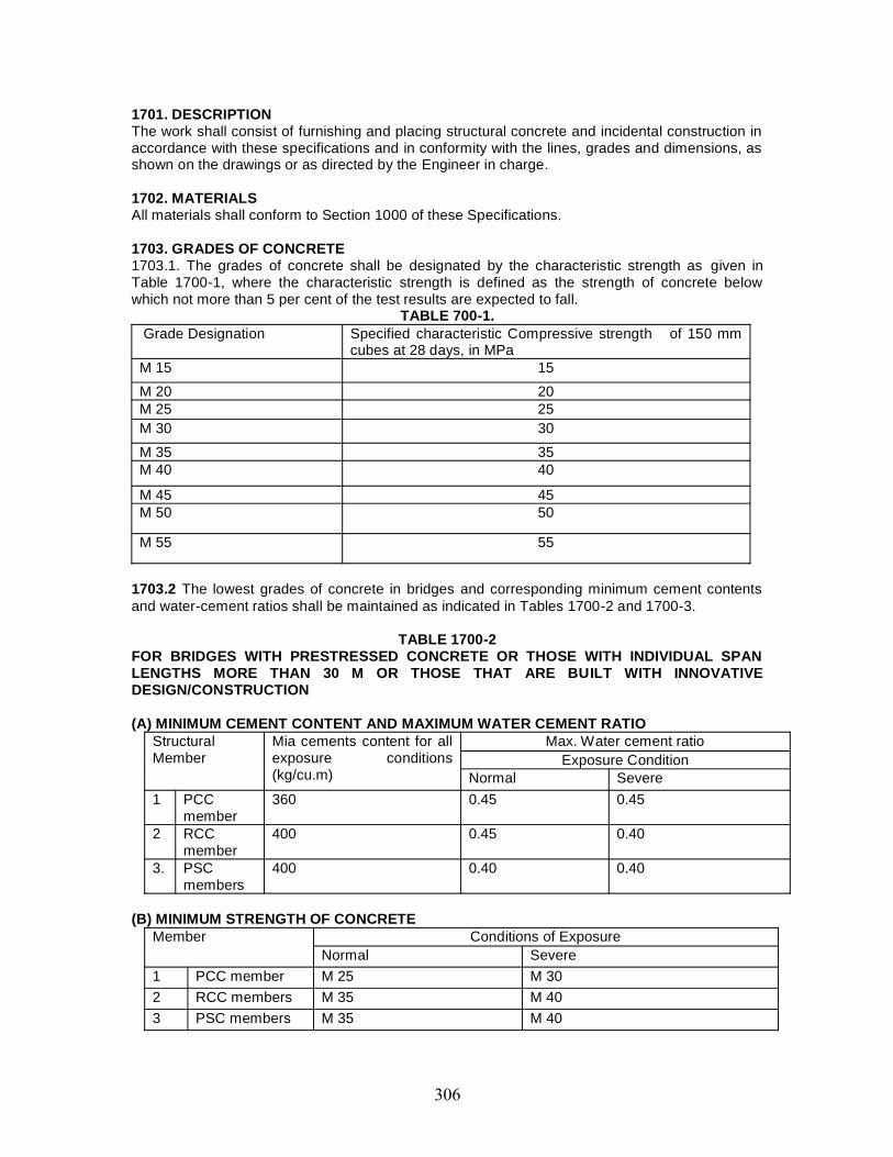
1701. DESCRIPTIONThe work shall consist of furnishing and placing structural concrete and incidental construction inaccordance with these specifications and in conformity with the lines, grades and dimensions, asshown on the drawings or as directed by the Engineer in charge.
1702. MATERIALSAll materials shall conform to Section 1000 of these Specifications.
1703. GRADES OF CONCRETE1703.1. The grades of concrete shall be designated by the characteristic strength as given inTable 1700-1, where the characteristic strength is defined as the strength of concrete belowwhich not more than 5 per cent of the test results are expected to fall.
TABLE 700-1.Grade Designation Specified characteristic Compressive strength of 150 mm
cubes at 28 days, in MPaM 15 15M 20 20M 25 25M 30 30M 35 35M 40 40
M 45 45M 50 50
M 55 55
1703.2 The lowest grades of concrete in bridges and corresponding minimum cement contentsand water-cement ratios shall be maintained as indicated in Tables 1700-2 and 1700-3.
TABLE 1700-2FOR BRIDGES WITH PRESTRESSED CONCRETE OR THOSE WITH INDIVIDUAL SPANLENGTHS MORE THAN 30 M OR THOSE THAT ARE BUILT WITH INNOVATIVEDESIGN/CONSTRUCTION
(A) MINIMUM CEMENT CONTENT AND MAXIMUM WATER CEMENT RATIOStructuralMember
Mia cements content for allexposure conditions(kg/cu.m)
Max. Water cement ratioExposure Condition
Normal Severe1 PCC
member360 0.45 0.45
2 RCCmember
400 0.45 0.40
3. PSCmembers
400 0.40 0.40
(B) MINIMUM STRENGTH OF CONCRETEMember Conditions of Exposure
Normal Severe1 PCC member M 25 M 302 RCC members M 35 M 403 PSC members M 35 M 40
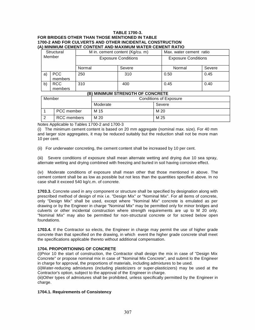
TABLE 1700-3.FOR BRIDGES OTHER THAN THOSE MENTIONED IN TABLE1700-2 AND FOR CULVERTS AND OTHER INCIDENTAL CONSTRUCTION(A) MINIMUM CEMENT CONTENT AND MAXIMUM WATER CEMENT RATIO
StructuralMember
M in. cement content (Kg/cu. m) Max. water cement ratioExposure Conditions Exposure Conditions
Normal Severe Normal Severea) PCC
members250 310 0.50 0.45
b) RCCmembers
310 400 0.45 0.40
(B) MINIMUM STRENGTH OF CONCRETEMember Conditions of Exposure
Moderate Severe1 PCC member M 15 M 202 RCC members M 20 M 25
Notes Applicable to Tables 1700-2 and 1700-3(i) The minimum cement content is based on 20 mm aggregate (nominal max. size). For 40 mmand larger size aggregates, it may be reduced suitably but the reduction shall not be more man10 per cent.
(ii) For underwater concreting, the cement content shall be increased by 10 per cent.
(iii) Severe conditions of exposure shall mean alternate wetting and drying due 10 sea spray,alternate wetting and drying combined with freezing and buried in soil having corrosive effect.
(iv) Moderate conditions of exposure shall mean other that those mentioned in above. Thecement content shall be as low as possible but not less than the quantities specified above. In nocase shall it exceed 540 kg/c.m. of concrete.
1703.3. Concrete used in any component or structure shall be specified by designation along withprescribed method of design of mix i.e. "Design Mix" or "Nominal Mix". For all items of concrete,only "Design Mix" shall be used, except where "Nominal Mix" concrete is emulated as perdrawing or by the Engineer in charge "Nominal Mix" may be permitted only for minor bridges andculverts or other incidental construction where strength requirements are up to M 20 only."Nominal Mix" may also be permitted for non-structural concrete or for screed below openfoundations.
1703.4. If the Contractor so elects, the Engineer in charge may permit the use of higher gradeconcrete than that specified on the drawing, in which event the higher grade concrete shall meetthe specifications applicable thereto without additional compensation.
1704. PROPORTIONING OF CONCRETE(i)Prior 10 the start of construction, the Contractor shall design the mix in case of "Design MixConcrete" or propose nominal mix in case of "Nominal Mix Concrete", and submit lo the Engineerin charge for approval, the proportions of materials, including admixtures to be used.(ii)Water-reducing admixtures (including plasticizers or super-plasticizers) may be used at theContractor’s option, subject to the approval of the Engineer in charge.(iii)Other types of admixtures shall be prohibited, unless specifically permitted by the Engineer incharge.
1704.1. Requirements of Consistency
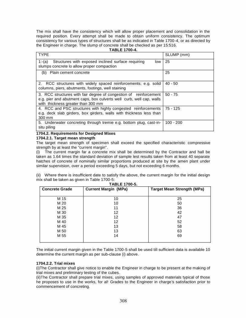
The mix shall have the consistency which will allow proper placement and consolidation in therequired position. Every attempt shall be made to obtain uniform consistency. The optimumconsistency for various types of structures shall be as indicated in Table 1700-4, or as directed bythe Engineer in charge. The slump of concrete shall be checked as per 15:516.
TABLE 1700-4.TYPE SLUMP (mm)
1:-(a) Structures with exposed inclined surface requiring lowslumps concrete lo allow proper compaction
25
(b) Plain cement concrete 25
2. RCC structures with widely spaced reinforcements; e.g. solidcolumns, piers, abutments, footings, well staining
40 - 50
3. RCC structures with fair degree of congestion of reinforcemente.g. pier and abutment caps, box culverts well curb, well cap, wallswith thickness greater than 300 mm
50 - 75
4. RCC and PSC structures with highly congested reinforcementse.g. deck slab girders, box girders, walls with thickness less than300 mm
75 - 125
5. Underwater concreting through tremie e.g. bottom plug, cast-in-situ piling
100 - 200
1704.2. Requirements for Designed Mixes1704.2.1. Target mean strengthThe target mean strength of specimen shall exceed the specified characteristic compressivestrength by at least the "current margin".(i) The current margin far a concrete mix shall be determined by the Contractor and hall betaken as 1.64 times the standard deviation of sample lest results taken from at least 40 separatehatches of concrete of nominally similar proportions produced at site by the amen plant undersimilar supervision, over a period exceeding 5 days, but not exceeding 6 months.
(ii) Where there is insufficient date to satisfy the above, the current margin for the initial designmix shall be taken as given in Table 1700-5:
TABLE 1700-5.Concrete Grade Current Margin (MPa) Target Mean Strength (MPa)
M 15M 20M 25M 30M 35M 40M 45M 50M 55
101011121212131314
255036424752586369
The initial current margin given in the Table 1700-5 shall be used till sufficient data is available 10determine the current margin as per sub-clause (i) above.
1704.2.2. Trial mixes(i)The Contractor shall give notice to enable the Engineer in charge to be present at the making oftrial mixes and preliminary testing of the cubes.(ii)The Contractor shall prepare trial mixes, using samples of approved materials typical of thosehe proposes to use in the works, for al! Grades to the Engineer in charge’s satisfaction prior tocommencement of concreting.
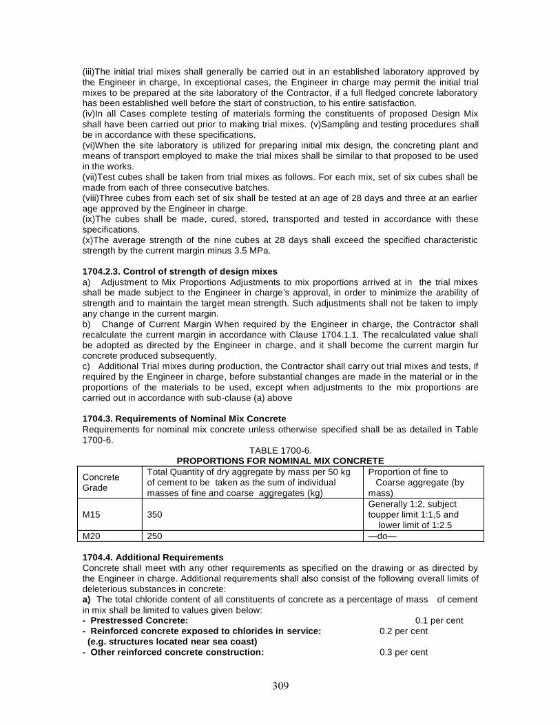
(iii)The initial trial mixes shall generally be carried out in an established laboratory approved bythe Engineer in charge, In exceptional cases, the Engineer in charge may permit the initial trialmixes to be prepared at the site laboratory of the Contractor, if a full fledged concrete laboratoryhas been established well before the start of construction, to his entire satisfaction.(iv)In all Cases complete testing of materials forming the constituents of proposed Design Mixshall have been carried out prior to making trial mixes. (v)Sampling and testing procedures shallbe in accordance with these specifications.(vi)When the site laboratory is utilized for preparing initial mix design, the concreting plant andmeans of transport employed to make the trial mixes shall be similar to that proposed to be usedin the works.(vii)Test cubes shall be taken from trial mixes as follows. For each mix, set of six cubes shall bemade from each of three consecutive batches.(viii)Three cubes from each set of six shall be tested at an age of 28 days and three at an earlierage approved by the Engineer in charge.(ix)The cubes shall be made, cured, stored, transported and tested in accordance with thesespecifications.(x)The average strength of the nine cubes at 28 days shall exceed the specified characteristicstrength by the current margin minus 3.5 MPa.
1704.2.3. Control of strength of design mixesa) Adjustment to Mix Proportions Adjustments to mix proportions arrived at in the trial mixesshall be made subject to the Engineer in charge’s approval, in order to minimize the arability ofstrength and to maintain the target mean strength. Such adjustments shall not be taken to implyany change in the current margin.b) Change of Current Margin When required by the Engineer in charge, the Contractor shallrecalculate the current margin in accordance with Clause 1704.1.1. The recalculated value shallbe adopted as directed by the Engineer in charge, and it shall become the current margin furconcrete produced subsequently,c) Additional Trial mixes during production, the Contractor shall carry out trial mixes and tests, ifrequired by the Engineer in charge, before substantial changes are made in the material or in theproportions of the materials to be used, except when adjustments to the mix proportions arecarried out in accordance with sub-clause (a) above
1704.3. Requirements of Nominal Mix ConcreteRequirements for nominal mix concrete unless otherwise specified shall be as detailed in Table1700-6.
TABLE 1700-6.PROPORTIONS FOR NOMINAL MIX CONCRETE
ConcreteGrade
Total Quantity of dry aggregate by mass per 50 kgof cement to be taken as the sum of individualmasses of fine and coarse aggregates (kg)
Proportion of fine toCoarse aggregate (by
mass)
M15 350Generally 1:2, subjecttoupper limit 1:1,5 and
lower limit of 1:2.5M20 250 —do—
1704.4. Additional RequirementsConcrete shall meet with any other requirements as specified on the drawing or as directed bythe Engineer in charge. Additional requirements shall also consist of the following overall limits ofdeleterious substances in concrete:a) The total chloride content of all constituents of concrete as a percentage of mass of cementin mix shall be limited to values given below:- Prestressed Concrete: 0.1 per cent- Reinforced concrete exposed to chlorides in service: 0.2 per cent
(e.g. structures located near sea coast)- Other reinforced concrete construction: 0.3 per cent

b) The total sulphuric anhydride (SO,) content of all the constituents of concrete as a percentageof mass of cement in the mix shall be limited lo 4 per cent
1704.5. Suitability of Proposed Mix ProportionsThe Contractor shall submit the following information for the Engineer in charge’s approval:a) Nature and source of each materialb) Quantities of each material per cubic meter of fully compacted concretec) Either of the following:(i) Appropriate existing data as evidence of satisfactory previous performance for the targetmean strength, current margin. Consistency and water/cement ratio and any other additionalrequirement(s) as specified.(ii) Full details of tests on trial mixes.d) Statement giving the proposed mix proportions for nominal mix concrete. Any change in thesource of material or in the mix proportions shall be subject to the Engineer in charge’s priorapproval,
1705. ADMIXTURES(i)Use of admixtures such as superplasticisers for concrete may be made with the approval of theEngineer in charge.(ii)As the selection of an appropriate concrete admixture is an integral part of the mix design, themanufacturers shall recommend the use of any one of his products only after obtaining completeknowledge of all the actual constituents of concrete as well as methodologies of manufacture,transportation and compaction of concrete proposed to be used in the project.
1706. SIZE OF COARSE AGGREGATEThe size {maximum nominal) of coarse aggregates for concrete to be used in variouscomponents shall be given as Table 1700-7.
TABLE 1700-7.
Components Maximum Nominal Size of CoarseAggregate (mm)
i) RCC well curb 20
ii) RCC/PCC welt steining 40
iii) Well tap or Pile CapSolid type piers and abutments 40
iv) RCC work in girders, slabs,wearing coal, kerb, approachslab, hollow piers andabutments, pier/abutment caps,piles
20
v) FSC work 20
vi) Any other item As specified by Engineer in charge
Maximum nominal size of aggregates shall also be restricted to the smaller of the followingvalues:a) 10 mm less than the minimum lateral clear distance between main reinforcementsb) 10 mm less than the minimum clear cover to the reinforcementsThe proportions of the various individual sizes of aggregates shall be so adjusted that the gradingproduces densest mix and the grading curve corresponds to the maximum nominal size adoptedfor the concrete mix.
1707. EQUIPMENT
Unless specified otherwise, equipment for production, transportation and compaction of concreteshall be as under:a) For Production of Concrete:i) For overall bridge length of less than 200 melees - batch type concrete mixer diesel or electricoperated, with a minimum size of 200 liters, automatic water measuring system and integralweighed (hydraulic/pneumatic type)ii) For overall bridge length of 200 meters or more - concrete batching and mixing plant fullyautomatic with minimum capacity of 15 c.m. Per hour. All measuring devices of the equipmentshall be maintained in a clean and serviceable condition. Its accuracy shall be checked over therange in use, when set up at each site and thereafter periodically as directed by the Engineer incharge. The accuracy of the measuring devices shall fall within the following limits:Measurement of Cement ± 3 per cent of the quantity °f cement in each batchMeasurement of Water ± 3 per cent of the quantity of water in each batchMeasurement of Aggregate ± 3 per cent of the quantity of aggregate in each batchMeasurement of Admixture ± 5 per cent of the quantity of admixture in each batchb) For Concrete Transportation depending upon actual requirement1) Concrete dumpers minimum 2 tonnes capacity2) Powered hoists minimum 0.5 tonnes capacity3) Chutes4) Buckets handled by cranes5) Transit truck mixer6) Concrete pump7) Concrete distributor booms8) Belt conveyor9) Cranes with skips10) Tremiec) For Compaction of Concrete:i) Internal vibrators size 25 mm lo 70 mmii) Form vibrators minimum 500 walls
iii) Screed vibrators full width of carriageway(Up to two lanes)
1708. MIXING CONCRETEConcrete shall be mixed either in a concrete mixer or in a batching and mixing plant, as per thesespecifications. Hand mixing shall not be permitted. The mixer or the plant shall be at an approvedlocation considering the properties of the mixes and the transportation arrangements availablewith the Contractor. The mixer or the plant shall be approved by the Engineer in charge. Mixingshall be continued till materials arc uniformly distributed and a uniform colour of die entire mass isobtained, and each individual particle of the coarse aggregate shows complete coating of mortarcontaining its proportionate amount of cement. In no case shall mixing be done for less than 2minutes. Mixers which have been out of use for more than 30 minutes shall be thoroughlycleaned before putting in a new batch. Unless otherwise agreed to by the Engineer in charge, thefirst batch of concrete from the mixer shall contain only two thirds of the normal quantity of coarseaggregate. Mixing plant shall be thoroughly cleaned before changing from one type of cement toanother.
1709. TRANSPORTING, PLACING AND COMPACTION OF CONCRETEThe method of transporting and placing concrete shall be approved by the Engineer in charge.Concrete shall be transported and placed as near as practicable to its final position, so that nocontamination, segregation or loss of its constituent materials Lakes place. Concrete shall not befreely dropped into place from a height exceeding 1.5 meters. When concrete is conveyed bychute, the plant shall be of such size and design as to ensure practically continuous flow. Slope ofthe chute shall be so adjusted that the concrete flows with out the use of excessive quantity ofwater and without any segregation of its ingredients. The delivery end of the chute shall be asclose as possible to the point of deposit. The chute shall be thoroughly flushed with water beforeand after each working period and the water used for this purpose shall be discharged outside the

formwork. All formwork and reinforcement contained in it shall be cleaned and made free fromstanding water, dust, snow or ice immediately before placing of concrete. No concrete shall beplaced in any part of the structure until the approval of the Engineer in charge has been obtained.If concreting is not started within 24 hours of the approval being given, it shall have to be obtainedagain from the Engineer in charge; Concreting then shall proceed continuously over the areabetween the construction joints. Fresh concrete shall not be placed against concrete which hasbeen in position for more than 30 minutes unless a proper construction joint is formed. Exceptwhere otherwise agreed to by the Engineer in charge, concrete shall be deposited in horizontallayers to a compacted depth of not more than 450 mm when internal vibrators are used and notexceeding 300 mm in all other cases. Concrete when deposited shall have a temperature of notless than 5 degrees Celsius, and not more than 40 degrees Celsius, It shall be compacted in itsfinal position within 30 minutes of its discharge from the mixer, unless carried in properlydesigned agitators, operating continuously, when this time shall be within 1 hour of the addition ofcement to the mix and within 30 minutes of its discharge from the agitator. It may be necessary toadd retarding admixtures to concrete if trials show that the periods indicated above areunacceptable. In all such matters, the Engineer in charge’s decision shall be final. Concrete shallbe thoroughly compacted by vibration or other means during placing and worked around thereinforcement, tendons or duct formers, embedded fixtures and into corners of the formwork toproduce a dense homogeneous void- free mass having the required surface finish. Whenvibrators are used, vibration shall be done continuously during the placing of each batch ofconcrete until the expulsion of air has practically ceased and in a manner that does not promotesegregation. Over vibration shall be avoided to minimize the risk of forming a weak surface layer.When external vibrators are used, the design of formwork and disposition of vibrator shall be suchas to ensure efficient compaction and to avoid surface blemishes. Vibrations shall not be appliedthrough reinforcement and where vibrators of immersion type are used, contact withreinforcement and all inserts like duels etc., shall be avoided. The internal vibrators shall beinserted in an orderly manner and the distance between insertions should be about one and ahalf times the radius of the area visibly affected by vibration. Additional vibrators in serviceablecondition shall be kept at site so that they can be used in the event of breakdowns. Mechanicalvibrators used shall comply with IS: 2502, IS: 2506, IS; 2514 and IS: 4656.
1710. CONSTRUCTION JOINTSConstruction joints shall be avoided as far as possible and in no case the locations of such jointsshall be changed or increased from those shown on the drawings, except with express approvalof the Engineer in charge. The joints shall be provided in a direction perpendicular to the memberaxis. Location, preparation of surface and concreting of construction joints shall conform to theadditional specifications given in Appendix 170011.
1711. CONCRETING UNDER WATERWhen it is necessary to deposit concrete under water, the methods, equipment, materials andproportions of mix to be used shall be got approved from the Engineer in charge before any workis started. Concrete shall contain 10 per cent more cement than that required for the same mixplaced in the dry.
Concrete shall not be placed in water having a temperature below 5 degrees Celsius,The temperature of the concrete, when deposited, shall not be less than 16 degrees Celsius, normore than 40 degrees Celsius. Coffer dams or forms shall be sufficiently tight to ensure still waterconditions, if practicable, and in any case to reduce the flow of water to less than 3 meters perminute through the space into which concrete is to be deposited.
Coffer dams or forms in still water shall be sufficiently tight to prevent loss of mortarthrough the joints in the walls. Pumping shall not be done while concrete is being placed, -or until24 hours thereafter. To minimize the formation of laitance, great care shall be exercised not todisturb the concrete as far as possible while it is being deposited.
All under water concreting shall be carried out by termite method only, using termite ofappropriate diameter. The number and spacing of the termites should be worked out to ensureproper concreting. The termite concreting when started should continue without interruption forthe full height of the member being concreted. The concrete production and placement equipmentshould be sufficient to enable the underwater concrete to be completed uninterrupted within thestipulated time. Necessary stand-by equipment should be available for emergency situation.
The top section of the termite shall have a hopper large enough to hold one full batch ofthe mix or the entire contents of the transporting bucket as the case may be. The termite pipeshall not be less than 200 mm in diameter and shall be large enough to allow a free flow ofconcrete and strong enough to withstand the external pressure of the water in which it issuspended, even if a partial vacuum develops inside the pipe. Preferably, flanged steel pipe ofadequate strength for the job shall be used. A separate lifting device shall be provided for eachtermite pipe with its hopper at the upper end. Unless the lower end of the pipe is equipped with anapproved automatic check valve, the upper end of the pipe shall be plugged with a wadding ofgunny sacking or other approved material before delivering the concrete to the termite pipethrough the hopper, so that when the concrete is forced down from the hopper to the pipe, it willForce the plug (and along with it any water in the pipe) down the pipe and out of the bottom end,thus establishing a continuous stream of concrete. It will be necessary to raise slowly the tremiein order to allow a uniform flow of concrete, but it shall not he emptied so that water is not allowedto enter above the concrete in the pipe. At times after placing of concrete is started and until allthe required quantity has been placed, the lower end of the tremie pipe shall be kept below thesurface of the plastic concrete. This will cause the concrete to build up from below instead offlowing out over the surface and thus avoid formation of layers of laitance. If the charge in thetermite is lost while depositing, the termite shall be raised above the concrete surface and unlessscaled by a check valve, it shall be replugged at the top end, as at the be ginning, before refillingfor depositing further concrete.
1712. ADVERSE WEATHER CONDITIONS1712.1. Cold Weather ConcretingWhere concrete is to be deposited at or near freezing temperature, precautions shall be taken toensure that at the time of placing, it has a temperature of not less than 5 degrees Celsius and thatthe temperature of the concrete shall be maintained above 4 degrees Celsius until it hasthoroughly hardened. When necessary, concrete ingredients shall be heated before mixing butcement shall not be heated artificially other than by the heat transmitted to it from otheringredients of the concrete Stock-piled aggregate may be heated by the use of dry heat or streamAggregates shall not be healed directly by gas or on sheet metal over fire. In general, thetemperature of aggregates or water shall not exceed 65 degrees Celsius, Salt or other chemicalsshall not be used for the prevention of freezing. No frozen material or materials containing iceshall be used. All concrete damaged by frost shall be removed. It is recommended that concreteexposed to freezing weather shall have entrained air and the water content of the mix shall notexceed 30 liters per 50 kg of cement.
1712.2. Hot Weather ConditionsWhen depositing concrete in very hoi weather, precautions shall be taken so that the
temperature of wet concrete does not exceed 40 degrees Celsius while placing. This shall beachieved by stacking aggregate under the shade and keeping them moist, using cold water,reducing the lime between mixing and placing to the minimum, cooling Formwork by sprinklingwater, starting curing before concrete dries out and restricting concreting as far as possible loearly mornings and late evenings. When ice is used Lo cool mixing water, it will be con side red apart of the water in design mix. Under no circumstances shall the mixing operation be consideredcomplete until ail ice in the mixing drum has melted.
The Contractor will be required to suite his methodology for the Engineer in charge’sapproval when temperatures of concrete arc likely lo exceed 40 degrees Celsius during the work.
1713. PROTECTION AND CURINGConcreting operations shall not commence until adequate arrangements for concrete curing havebeen made by the Contractor. Curing and protection of concrete shall start immediately aftercompaction of the concrete to protect it from:a) Premature drying out particularly by solar radiation and windb) High internal thermal gradientsc) Leaching out by rain and flowing waterd) Rapid cooling during the first few days after placinge) Low temperature or frostf) Vibration and impact which may disrupt the concrete and interfere with its bond to thereinforcement Where members are of considerable size and length , with high cement content,accelerated curing methods may be applied, as approved by the Engineer in charge.
1713.1. Water CuringWater for curing shall be as specified in Section 1000. Sea water shall not be used for curing.Sea water shall not come into contact with concrete members unless it has attained adequatestrength.
Exposed surfaces of concrete shall be kept continuously in a damp or wet condition byponding or by covering with a layer of sacks, canvas, Hessian or similar materials and shall bekepi constantly wet for a period of not less than 14 days from the date of placing of concrete.
1713.2. Steam CuringWhere steam curing is adopted, it shall be ensured that it is done in a suitable enclosure tocontain the live steam in order 10 minimize moisture and heat losses. The initial application of thesteam shall be after about four hours of placement of concrete to allow the initial set of theconcrete 10 take place.
Where readers are used, the waiting period before application of the steam shall beincreased to about six hours.
The steam shall be at 100 per cent relative humidity to prevent loss of moisture and toprovide excess moisture for proper hydration of the cement. The application of steam shall not hedirectly on the concrete and the ambient air temperature shall increase at a rate not exceeding 5degrees Celsius per hour until a maximum temperature of 60 degrees Celsius to 70 degreesCelsius is reached. The maximum temperature shall be maintained until the concrete hasreached the desired strength.
When steam curing is discontinued, the ambient air temperature shall not drop at a rateexceeding 5 degrees Celsius per hour until a temperature of about 10 degrees Celsius above thetemperature of the air 10 which the concrete will be exposed, has been reached. The concreteshall not be exposed to temperatures below freezing for at least six days after curing.
1713.3. Curing CompoundsCuring compounds shall only be permuted in special circumstances and will require specificapproval of the Engineer in charge; Curing compounds shall not be used on any surface whichrequires further finishing to be applied. All construction joints shall be moist, cured and no curingcompound will be permitted in locations where concrete surfaces are required to be bondedtogether.
Curing compounds shall be continuously agitated during use. All concrete cured by thismethod shall receive two applications of the curing compound. The first coat shall be appliedimmediately after acceptance of concrete finish. If the surface is dry, the concrete shall besaturated with water and curing compound applied as soon as the surface film of water
disappears. The second application shall be made after the first application has set. Placement inmore than two coats may be required to prevent streaking.
1714. FINISHINGImmediately after the removal of forms, exposed bars or bolls, if any, shall be cut inside theconcrete member to a depth of at least 50 mm below the surface of the concrete and the resultingholes filled with cement mortar. All fins caused by form joints, all cavities produced by the removalof form ties and all other holes and depressions, honeycomb spots, broken edges or corners, andother defects, shall be thoroughly cleaned, saturated with water, and carefu lly pointed andrendered true with mortar of cement and fine aggregate mixed in the proportions used in thegrade of concrete that is being finished and of as dry a consistency as is possible to use.Considerable pressure shall be applied in filling and pointing to ensure thorough tilling in all voids.Surfaces which have he en pointed shall be kept moist for a period of twenty four hours. Specialpre-packaged proprietary mortars shall be used where appropriate or where specified in thedrawing.
All construction and expansion joints in the completed work shall be left carefully tooledand free from any mortar and concrete. Expansion joint filler shall be left exposed for its full lengthwith clean and true edges. Immediately on removal of. Forms, the concrete work shall beexamined by the Engineer in charge before any defects arc made good.
a) The work that has sagged or contains honeycombing to an extent detrimental ion structuralsafety or architectural appearance shall be rejected.
b) Surface defect of a minor nature may/ be accepted. On acceptance, of such work by theEngineer in charge, the same shall be rectified as directed by the Engineer in charge,
1715. TOLERANCESTolerances for dimensions/shape of various components shall be as indicated in thesespecifications or shown on the drawings or as directed by the Engineer in charge.
1716. TESTS AND STANDARDS OF ACCEPTANCE1716.1. Concrete shall conform to the surface finish and tolerance as prescribed in thesespecifications for respective components,
1716.2. Random sampling and lot by lot of acceptance inspection shall be made for the 28 dayscube strength of concrete.
1716.2.1. Concrete under acceptance shall be notionally divided into lots for the purpose ofsampling, before commencement of work. The delimitation of lots shall be determined by thefollowing:(i) No individual lot shall be more than 30 c.m. in volume(ii) At least one cube forming an item of the sample, representing the lot shall be taken fromconcrete of the same grade and mix proportions cast on any day.(iii) Different grades of mixes of concrete shall be divided into separate lots(iv) Concrete of a lot, shall be used in the same identifiable component of the bridge
1716.2.2. Sampling and testing1. Concrete for making 3 test cubes shall be taken from a batch of concrete at point of deliveryinto construction, according to procedure hid down in 15:1199.2. A random sampling procedure to ensure that each of the concrete batches forming the lotunder acceptance inspection has equal chance of being chosen for taking cubes shall beadopted.
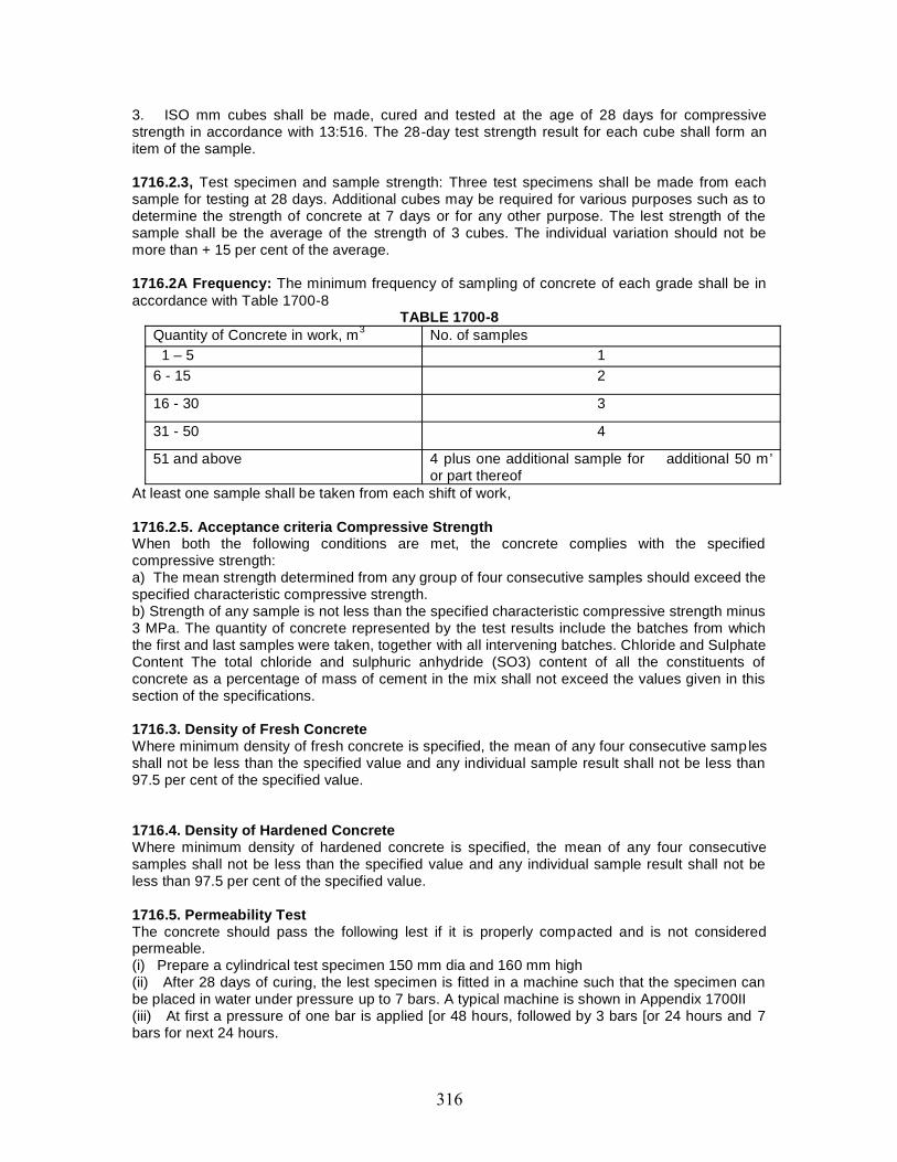
3. ISO mm cubes shall be made, cured and tested at the age of 28 days for compressivestrength in accordance with 13:516. The 28-day test strength result for each cube shall form anitem of the sample.
1716.2.3, Test specimen and sample strength: Three test specimens shall be made from eachsample for testing at 28 days. Additional cubes may be required for various purposes such as todetermine the strength of concrete at 7 days or for any other purpose. The lest strength of thesample shall be the average of the strength of 3 cubes. The individual variation should not bemore than + 15 per cent of the average.
1716.2A Frequency: The minimum frequency of sampling of concrete of each grade shall be inaccordance with Table 1700-8
TABLE 1700-8Quantity of Concrete in work, m3 No. of samples
1 – 5 16 - 15 2
16 - 30 3
31 - 50 4
51 and above 4 plus one additional sample for additional 50 m’or part thereof
At least one sample shall be taken from each shift of work,
1716.2.5. Acceptance criteria Compressive StrengthWhen both the following conditions are met, the concrete complies with the specifiedcompressive strength:a) The mean strength determined from any group of four consecutive samples should exceed thespecified characteristic compressive strength.b) Strength of any sample is not less than the specified characteristic compressive strength minus3 MPa. The quantity of concrete represented by the test results include the batches from whichthe first and last samples were taken, together with all intervening batches. Chloride and SulphateContent The total chloride and sulphuric anhydride (SO3) content of all the constituents ofconcrete as a percentage of mass of cement in the mix shall not exceed the values given in thissection of the specifications.
1716.3. Density of Fresh ConcreteWhere minimum density of fresh concrete is specified, the mean of any four consecutive samplesshall not be less than the specified value and any individual sample result shall not be less than97.5 per cent of the specified value.
1716.4. Density of Hardened ConcreteWhere minimum density of hardened concrete is specified, the mean of any four consecutivesamples shall not be less than the specified value and any individual sample result shall not beless than 97.5 per cent of the specified value.
1716.5. Permeability TestThe concrete should pass the following lest if it is properly compacted and is not consideredpermeable.(i) Prepare a cylindrical test specimen 150 mm dia and 160 mm high(ii) After 28 days of curing, the lest specimen is fitted in a machine such that the specimen canbe placed in water under pressure up to 7 bars. A typical machine is shown in Appendix 1700II(iii) At first a pressure of one bar is applied [or 48 hours, followed by 3 bars [or 24 hours and 7bars for next 24 hours.
(iv) After the passage of the above period, the specimen is taken out and split in the middle bycompression applied on two round bars on opposite sides above and below.(v) The water penetration in the broken core is to he measured with a scale and the depth ofpenetration assessed in mm (max. permissible limit 25 mm), 1716.6. If the concrete is not able tomeet any of the standards of acceptance as prescribed, the effect of such deficiency on thestructure shall be investigated by the Contractor as directed by the Engineer in charge. TheEngineer in charge may accept the concrete as sub-standard work. Any additional work requiredby the Engineer in charge for such acceptance shall be carried our. by the Contractor at his cost.In case the concrete is not found to be acceptable after investigation, the Contractor shall removethe rejected concrete forthwith.
1717. MEASUREMENTS FOR PAYMENTStructural concrete shall be measured in cubic meters. In reinforced or prestressed concrete, thevolume occupied by reinforcement or prestressing cables and sheathing shall not be deducted.The slab shall be measured as running continuously through and beam as me portion below theslab.
1718. RATEThe contract unit rate for structural concrete shall cover costs of all materials, labour, tools, plantand equipment required for mixing, transporting and placing in position, vibrating and compacting,finishing and curing as per this Section or as directed by the Engineer in charge, including allincidental expenses, sampling and testing, quality assurance and supervision. Unless mentionedseparately as an item in the Contract, the contract unit rate for concrete shall also include the costof providing, fixing and removing formwork required for concrete work as per Section 1500.
Where concrete is found to be acceptable as sub-standard work, the Contractor shall paya discount over the contract unit rate, as decided by the Engineer in charge. For deficiency incompressive strength of concrete when accepted by the Engineer in charge, the reduction in ratemay be applied as under
Percent reduction = Design Strength - Observed Strength 100Design Strength
1800 PRESTRESSING

CONTENT
Clause No Description1801 DESCRIPTION
1802 MATERIALS
1803 TESTING OF PRESTRESSING STEEL AND ANCHORAGES
1804 WORKMANSHIP
1805 SUPERVISION
1806 TENSIONING EQUIPMENT
1807 POST-TENSIONING
1808 GROUTING OF PRESTRESSED TENDONS
1809 PRE-TENSIONING
1810 SAFETY PRECAUTIONS DURING TENSIONING
1811 TRANSPORTATION AND STORAGE OF UNITS
1812 TOLERANCES
1813 TESTS AND STANDARDS OF ACCEPTANCE
1814 MEASUREMENTS FOR PAYMENT
1815 RATE
1801. DESCRIPTIONStructural concrete containing prestressed steel reinforcement to introduce recompression istermed as prestressed concrete.
The work shall be carried out in accordance with the drawing and these specifications oras approved by the Engineer in charge.
Concrete and untensioned steel for the construction of prestressed concrete membersshall conform to the requirements of sections 1700 and 1600 for Structural Concrete and SteelReinforcement respectively in so far as the requirements of these Sections apply and are notspecifically modified by requirements set forth herein.
1802. MATERIALS1802.1. All materials shall conform to Section 1000.1802.2. Sheathing1802.2.1. The sheathing ducts shall be of the spiral corrugated type. Unless otherwise specified,the material shall be Cold Rolled Cold Annealed (CRCA) Mild Steel conforming to IS : 513intended for mechanical treatment and surface refining but not for quench hardening ortempering.
The material shall normally be bright finished. However, where specified, as in case ofuse in aggressive environment, galvanized or lead-coated mild steel strips shall be used.
The thickness of sheathing shall be as shown on the drawing, but shall not be less than0.3 mm, 0.4 mm and 0.5 mm for sheathing ducts having internal diameter of 50 mm, 75 mm and90 mm respectively. For bigger diameter of ducts, thickness of sheathing shall be based onrecommendations of prestressing system supplier or as directed by the Engineer in charge.
The sheathing shall conform to the requirement as per tests specified in Appendix1800/1.
For major projects, the sheathing ducts should preferably be manufactured at the projectsite utilising appropriate machines. With such an arrangement, long lengths of sheathing ductsmay be used with consequent reduction in the number of joints and couplers. Where sheathingduct joints are unavoidable, such joints shall be made slurry tight by the use of corrugatedthreaded sleeve couplers which may be tightly screwed onto the outer side of the sheathingducts.
The length of the coupler should not be less than 150 mm but should be increased up to200 mm wherever practicable. The joints between the ends of the coupler and the duel shall besealed with adhesive scaling tape lo prevent penetration of cement slurry during concreting. Thecouplers of adjacent ducts should be staggered wherever practicable. As far as possible,couplers should not be located in curved zones. The corrugated sleeve couplers are beingconveniently manufactured using the sheath making machine with the next higher size of die set.
1802.2.2. The internal area of the sheathing duct shall be in accordance with therecommendations of the system manufacturer and shall be about three times the area of thetendons. In case of 6T13, 12T13 and 19T13 sizes of tendons comprising 12/13 mm dia strands,the inner diameter of the sheathing shall not be less than 50 mm, 15 mm and 90 mm respectivelyor those shown in the drawing, which ever is greater.
Where prestressing tendons are required to be threaded after concreting the diameter ofsheathing shall be about 5 mm larger than that required as above.
1802.2.3. In severe environment, cables shall be threaded after concreting. In such cases atemporary tendon shall be inserted in the sheathing or the sheathing shall be stiffened by othersuitable method during concreting.
1802.3. Apchorages1802.3.1. Anchorages shall be procured from authorized manufacturers only. Anchorages shallconform to BS: 4447. Test certificates from a laboratory fully equipped to carry out the tests shallbe furnished to the Engineer in charge. Such test certificates shall not be more than 12 monthsold at the time of making the proposal for adoption of a particular system for the project.
No damaged anchorages shall be used. Steel parts shall be protected from corrosion atall times. Threaded parts shall be protected by greased wrappings and tapped holes shall beprotected by suitable plugs until used. The anchorage components shall be kept free from mortarand loose rust and any other deleterious coaling.
1802.3.2. Swages of prestressing stand and button-heads of prestressing wire, where providedshall develop strength of at least. 95 per cent of the specified breaking load of the strand or wireas the case may be. Where swaging/button -heading is envisaged, the Contractor shall furnishdetails of his methodology and obtain approval of the Engineer in charge, prior to his taking upthe work.
1802.3.3. Untensioned Steel reinforcements, around anchorages shall conform to the details ofprestressing system and as shown on the drawing.
1803. TESTING OF PRESTRESSING STEEL AND ANCHORAGESAll materials specified for testing shall be furnished free of cost and shall be delivered in
time for tests to be made well in advance of anticipated time of use.All wire, strand or bars to be shipped to the site shall be assigned a lot number and
tagged for identification purposes. Anchorage assemblies to be shipped shall be like -wiseidentified.
All samples submitted shall be representative of the lot to be furnished and in the case ofwire or strand, shall be taken from the same master roll. The Contractor shall furnish samples ofat least 5.0 m length selected from each lot for testing. Also, two anchorage assemblies completewith distribution plates of each size or types1 to be used shall be furnished along with shortlengths of strands as required.
1804 WORKMANSHIP1804.1. CleaningTendons shall be free from loose rust, oil, grease, tar, paint, mud or any other deleterioussubstance. Cleaning of the steel may be carried out by immersion in suitable solvent solutions,wire brushing or passing through a pressure box containing carborundum powder. However, thetendons shall not be brought to a polished condition.
1804.2. StraighteningHigh tensile steel wire and strand shall be supplied in coils of sufficiently large diameter such thattendons shall retain their physical properties and shall be straight as it unwinds from the coil.Tendons of any type that are damaged, kinked or bent shall not be used.
The packing of presuessing wire/strand shall be removed only just prior to making ofcable for placement. Suitable stands shall be provided to facilitate uncoiling of ires/strandswithout damage to steel. Care shall be taken to avoid the possibility of steel coming into contactwith the ground.
1804.3. Positioning1804.3.1. Post-TensioningPrestressing tendons shall be accurately located and maintained in position, both vertically andhorizontally, as per drawings.
Tendons shall be so arranged that they have a smooth profile without sudden bends orkinks.
The location of prestressed cables shall be such as to facilitate easy placement andvibration of concrete in between the tendons. High capacity tendon shall be used to reduce thenumber of cables thereby eliminating the necessity of grouping. The selected profiles of thetendons shall be such that their anchorages arc not located in the top deck surface. Where two ormore rows of cables have to be used, the cables shall be vertically in line to enable easy flow ofconcrete, the clear vertical and horizon tal distances between any two cables shall in no case beless than 100mm anywhere along the length of the superstructure. Where precast segments areused, the clear distance shall be at least 150 mm.
Sheathing shall be placed in correct position and profile by providing suitable ladders andspacers. Such ladders may be provided at intervals of approximately 1.0 m. Sheathing shall betied rigidly with such ladders/spacer bars so that they do not get disturbed during concreting.
The method of supporting and fixing shall be such that profile of cables is not disturbedduring vibrations, by pressure of wet concrete, by workmen or by construction traffic.
Sheathing in which the permanent tendon will not be in place during concreting shallhave a temporary tendon inserted or shall be stiffened by some other method to the approval ofthe Engineer in charge. The temporary tendon shall be pulled out before threading the permanenttendon into place by a special threading machine or other contrivance.
Where possible tendons shall not be placed until immediately prior to stressing. Tendonsshall be handled with care to avoid damage or contamination, to either the tendon or thesheathing. Any tendons damaged or contaminated shall be cleaned or replaced.
1804.3.2. Pre-Tensioning, Prestressing steel shall be accurately located and maintained inposition, both vertically and horizontally, as per drawings.
1804.3.3. Each anchorage device shall be set square to the line of action of the correspondingprestressing tendon and shall be positioned securely to prevent movement during concreting.
The anchorage devices shall be cleaned to the satisfaction of the Engineer in chargeprior to the placing of concrete. After concreting, any mortar or concrete which adheres to bearingor wedging surfaces shall be removed immediately.
1804.4. CuttingCutting and trimming of wires or strands shall be done by suitable mechanical or flame
cutters. When a flame cutter is used, care shall be taken to ensure that the flame docs not comein contact with other stressed steel. The location of flame cutting of wire or strand shall be keptbeyond 75 mm of where the tendon will be gripped by the anchorage or jacks.
In post-tensioning the ends of Presuessing steel projecting beyond the anchorages, shallbe cut after the grout has set.
1804.5. Protection of Prestressing SteelPresuessing steel shall be continuously protected against corrosion, unti l grouted. The
corrosion protector shall have no deleterious effect on the steel or concrete or on the bond
strength of steel to concrete. Grouting shall conform to these specifications or as directed by theEngineer in charge.
In the case of external prestressing, steel shall be encased in suitable polyethylene pipesbefore grouting,
1804.6. SheathingThe joints of all sheathings shall be water-tight. Special attention shall be paid to the
junction at the anchorage end, where the sheathing must tightly fit on the protruding trumpet endof anchorage and thereafter sealed preferably with heat shrink tape, to make it waterproof.
The heat-shrink tape is supplied in the form of bandage rolls which can be used for alldiameters of sheathing ducts. The bandage is coated on the underside with a heat sensitiveadhesive so that after heating the bandage material shrinks on the sheathing duct and ensuresformation of a leak-proof joint. The heating is affected by means of a soft gas flame.
A sheath making machine should be positioned at the site of work for large projects sothat sheathing can be prepared as and when it is required for construction.
The sheathing and all joints shall be water tight. Any temporary opening in the sheathingshall be satisfactorily plugged and all joints between sheathing and any other part of meprestressing system shall be effectively sealed to prevent entry of mortar, dust, water or otherdeleterious matter. Sheathing shall be neatly fitted at joints without internal projection or reductionof diameter.
Enlarged portions of the sheathing at couplings or anchorages shall be of sufficient lengthto provide for the extension of the tendons.
1804.7. Grout VentsGrout vents of at least 20 mm diameter shall be provided at both ends of the sheathing
and at all valleys and crests along its length. Additional vents with plugs shall also be providedalong the length of sheathing such that the spacing of consecutive vents do not exceed 20 m.Each of the grout vents shall be provided with a plug or similar device capable of withstanding apressure of 1.0 MPa without the loss of water, air pressure or grout,
1804.8 AnchoragesAll bearing surfaces of the anchorages shall be cleaned prior to concreting and
tensioning.Anchor cones, blocks and plates shall be securely positioned and maintained during
concreting such that the centre line of the duct passes axially through the anchorage assembly.The anchorages shall be recessed from the concrete surface by a minimum coyer of 100 mm.After the prestressing operations are completed and prestressing wires/strands are cut, thesurface shall be painted with two coats of epoxy of suitable formulation having a dry filmthickness of 80 microns per coat and entire recess shall be filled with concrete or non-shrink/pre-packaged mortar or epoxy concrete.
1804.9. Structural ConcreteStructural concrete shall conform to Section 1700. The formwork shall conform to Section 1500.
1805. SUPERVISIONAll prestressing and grouting operations shall be undertaken by trained personnel only. Arepresentative of supplier of the prestressing system shall be present during all tensioning andgrouting operations and shall ensure, monitor and certify their correctness.
1806. TENSIONING EQUIPMENT
All tensioning equipment shall be procured from authorized manufacturers only and be approvedby the Engineer in charge prior to use. Where hydraulic jacks are used, they shall be power-driven unless otherwise approved by the Engineer in charge. The tensioning equipment shallsatisfy the following requirements:
(i) The means of attachments of the prestressing steel to the jack of any other tensioningapparatus shall be safe and secure.
(ii) Where two or more wires/strands constitute a tendon, a single multiple stressing jack shall beused which is capable of tensioning simultaneously all the wires/ strands of the tendon. Suitablefacilities for handling and attaching the multiple jacks lo the tendons shall be provided.
(iii) The tensioning equipment shall be such that it can apply controlled total force gradually onthe concrete without inducing dangerous secondary stresses in steel, anchorage or concrete; and
(iv) Means shall be provided for direct measurement of the force by use of dynamometers orpressure gauges fitted in the hydraulic system itself to determine the pressure in the jacks.Facilities shall also be provided for the linear measurement of the extension of prestressing steelto the nearest mm and of any slip of the gripping devices at transfer. All dynamo meters andpressure, gauges including a master gauge shall be calibrated by an approved laboratoryimmediately prior to use and then at intervals not exceeding 3 months and the true forcedetermined from the calibration curve. Pressure gauges shall be concentric scale type gaugesaccurate to within two per cent of their full capacity. The minimum nominal size of gauge shall be100 mm. The gauge shall be so selected that when the tendon is stressed to 75 per cent of itsbreaking load, the gauge is reading between 50 per cent and 80 per cent of its full capacity.Suitable safety devices shall be fitted to protect pressure gauges against sudden release ofpressure. Provision shall be made for the attachment of the master gauge to be used as a checkwhenever requested for by the Engineer in charge.
1807. POST-TENSIONINGTensioning force shall be applied in gradual and steady steps and carried out in such a mannerthat the applied tensions and elongations can be measured at all times. The sequence o fstressing, applied tensions and elongations shall be in accordance with the approved drawing oras directed by the Engineer in charge.
It shall be ensured that in no case, the load is applied to the concrete before it attains thestrength specified on the drawing or as stipulated by the prestressing system supplier, whicheveris more.
After prestressing steel has been anchored, the force exerted by the tensioningequipment shall be decreased gradually and steadily so as to avoid shock to the prestress ingsteel or anchorage.
The tensioning force applied to any tendon shall be determined by direct reading of thepressure gauges or dynamo-meters and by comparison of the measured elongation with thecalculated elongation. The calculated elongation shall be invariably adjusted with respect to themodulus of elasticity of steel for the particular lot as given by the manufacturer. The differencebetween calculated and observed tension and elongation during prestressing operations shall beregulated as follows:
a) If the calculated elongation is reached before the specified gauge pressure is obtained,continue tensioning till attaining the specified gauge pressure, provided the elongation does notexceed 1.05 times the calculated elongation. If 1.05 times the calculated elongation is reachedbefore the specified gauge pressure is attained, stop stressing and inform the Engineer in charge.
b) If the calculated elongation has not been reached at the specified gauge pressure, continuetensioning by intervals of 5 kg/sq, c.m. until the calculated elongation is reached provided thegauge pressure does not exceed 1.05 times the specified gauge pressure.
c) If the elongation at 1.05 times the specified gauge pressure is less. Than 0.95 times thecalculated elongation, the following measures must be taken, in succession, to determine thecause of this lack of discrepancy:
i) Check the correct functioning of the jack, pump and leads.
ii) Detention the cable. Slide it in its duct to check that it is not blocked by mortar which hasentered through holes in the sheath. Retention the cable if free.
iii) Re -establish the modulus of elasticity of steel for the particular lot from an approvedlaboratory. If the required elongation is still not obtained, further finishing operations such ascutting or staling, should not be undertaken without the approval of the Engineer in charge.
d) When stressing from one end only, the slip at the end remote from the jack shall beaccurately measured and an appropriate allowance made in the measured extension at thejacking end. A complete record of prestressing operations along with elongation and jackpressure data shall be maintained in the format given in Appendix 1800HI. The number of stagesof prestressing and grouting shall be reduced to a minimum, preferably 2 in the case of simplysupported girders.
1808. GROUTING OF PRESTRESSED TENDONSGrouting shall conform to Appendix I800HII; a record of grouting operations shall be maintainedin the format given in Appendix 1800! IV.
1809. PRE-TENSIONING1809.1. GeneralThe planning and construction aspects of the tensioning bed, .tensioning bench, butments atlocation of anchorage, steam curing system, formwork of the concrete elements andarrangements for demoulding, lifting, stacking and transportation of the pre-tensioned concreteelements are all specialized items and shall be entrusted to Engineer in charges specificallyexperienced in this type of work.
1809.2. Stressing Bed for Pre -tensioning the abutments and bed for pre-tensioning of tendonsshall be designed to withstand the total tensioning force. A notice shall be displayed adjacent tothe stressing bed showing the maximum tensioning force permitted.Where concrete elements are cast and prestressed individually, the stressing bench or mouldsshall be rigid enough to sustain the reaction of the prestressing force without distortion. In thelong line method of prestressing, sufficient locator plates should be distributed throughout thelength of the bed to ensure that the wires are maintained in their proper position duringconcreting. The moulds shall be free lo sliding in the direction of their length and thus permit thetransfer of the prestressing force lo all the concrete Elements along the whole line. Sufficientspace shall be left in between the ends of concrete elements to permit access for cutting thestrands/wires after transfer. Hold downs or deflectors shall be used for holding or deflecting thetendons in required position firmly. Deflectors which are in contact with the tendon shall have adiameter not less than the tendon or 15 mm, whichever is greater. The tensioning force requiredto be applied as stated on the drawings shall be the force remaining in the strands/wires after all
strands/wires have been anchored to the abutments of the stressing bed and after the anchorageslip has already taken place. The tensioning force shall be determined by direct reading of thepressure gauges or dynamo-meters and by the measured elongation after slip. The Contractorshall submit method of tensioning the tendons including the arrangement and layout ofprestressing beds and all tendon deflection points to the Engineer in charge for approval beforemanufacture commences. The Contractor shall carry out trial stressing operations to establish thefrictional resistance offered by the hold-downs and the slip during anchoring. Where sheathing ofpre-tensioned tendons is required to prevent bond over a specified length, it shall consist ofplastic tubing or other material approved by the Engineer in charge and shall be of a quality,diameter and thickness such that bond shall be effectively prevented. The tubing shall befastened to the tendon in such a manner that cement mortar cannot enter. The Engineer incharge may order that the pull- in of the tendon be measured during the transfer of Prestress. TheContractor shall also submit calculations showing that the hold downs have been designed andconstructed to withstand concentrated loads resulting from the application of the tensioning force.
1809.3. Tensioning .ProcedureThe tensioning, of the wires and strands shall be done not too much in advance of concreting.The tensioning force shall be applied gradually and uniformly, In order to remove slack and to lifttendons off the bed floor, an initial force approved by the Engineer in charge shall be applied tothe tendons. Allowance shall be made for this force in calculating the required elongation.Tendons shall be marked for measurement of elongation after the initial force has been applied.When required by the Engineer in charge, tendons shall be marked at both the jacking end anddead end of the stressing bed and at couplers if used so that slip and draw-in may be measured.Where deflected strands have been specified, the Engineer in charge may direct the elongationor strain gauge measurements be taken at various positions along the lend on to determine theforce in the tendon at those positions.
1809.4. Transfer of PrestressWhile the process of tensioning can be accomplished by means of hydraulic jacks, some positivemechanical means shall be provided to maintain the tension during the entire period between thetensioning of the wires/strands and transfer of the prestressing force to the co ncrete element.Transfer of Prestress shall not proceed until the Engineer in charge has approved the proposedmethod. Tendons and deflection devices shall be released in such a pre-determined order thatunacceptable tensile stresses are not induced in the concrete. Prior to transfer of the force to theunits, all tendons shall be tested for tightness and any loose tendon shall be reported to theEngineer in charge who will decide whether the units affected shall be rejected. The Engineer incharge may require that tendons be marked at each end of any unit to allow measurement of thepull- in of the concrete. Tendons shall be released gradually and preferably simultaneously.Under no circumstances shall tendons be cut while under tension. On completion of the transferof Prestress, the projecting lengths of tendon shall be cut off flush with the end surface of the unit,unless otherwise shown, by a method approved by the Engineer in charge. In no case shall thetransfer of prestressing force to the concrete elements take place before concrete attains thestrength specified in the drawings. To determine the specified strength, additional cube testingshall be undertaken at the Contractor's cost. In case steam curing is employed, me cubes shallbe placed in the same environment as the concrete elements to obtain an accurate assessmentof concrete strength at the time of transfer, The sequence of transfer of prestressing force shallbe done strictly as indicated in the drawings and ensuring that eccentricities of the presiressingforce in the vertical and horizontal directions of the concrete element is a minimum during theentire sequence. The maximum slip of any tendon during transfer shall not exceed 3mm at anyend of the concrete element. In case this slip is exceeded, the concrete element in question shallbe rejected.

1809.5. Protection of EndsThe exposed ends of the tendons and the .concrete surfaces of the ends of the units shall be wirebrushed clean of all rust, loose mortar, grease and din. The exposed ends of the tendons andconcrete surface within 50 mm of tendons shall be then abraded to provide a clean soundsurface. Epoxy tar paint suitably formulated to give a dry film thicknessof 80 microns per coat shall then be immediately applied over the ends of the tendons unlessotherwise directed. A second coat of paint shall be applied prior to the drying outof the first coat.
1810. SAFETY PRECAUTIONS DURING TENSIONINGCare shall be taken during tensioning to ensure the safety of all persons in the vicinity.Jacks shall be secured in such a manner that they will be held in position, should they lose theirgrip on the tendons. No person shall be allowed to stand behind the jacks or close to the line ofthe tendons while tensioning is in progress. The operations of the jacks and the measurement ofthe elongation and associated operations shall be carried out in such a manner and from such aposition that the safety of all concerned is ensured.A safety barrier shall be provided at both ends to prevent any tendon, which might become loosefrom recoiling unchecked. During actual tensioning operation, warning sign shall be displayed atboth ends of the tendon. After prestressing, concrete shall neither be drilled nor any cut norchipped away or disturbed, without express approval of the Engineer in charge. No welding shallbe permitted on or near tendons nor shall any heat be applied to tendons. Any tendon which hasbeen affected by welding, weld spatter or heat shall be rejected.
1811. TRANSPORTATION AND STORAGE OF UNITSPrecast girders shall be transported in an upright position. Points of support and the direction ofreactions with respect to the girder shall approximately be the same during transportation, andstorage as when the girder is placed in final position. When members are to be stacked, theyshall be firmly supported at such bearing positions as will ensure that the stresses induced inthem are always less than the permissible design stresses. Further, inclined side supports shallbe provided at the ends and' along the length of a precast girder to prevent lateral movements ofinstability. Care shall be taken during storage, hoisting and handling of the precast units toprevent their cracking or being damaged. Units damaged by improper storing or handling shall bereplaced by the Contractor at his expense.
1812. TOLERANCESPermissible tolerances for positional deviation of Prestressing tendons shall be limited to thefollowing:a) Variation from the specified horizontal profile : 5 mmb) Variation from the specified vertical profile : 5 nunc) Variation from the specified position in member : 5 mm
1813. TESTS AND STANDARDS OF ACCEPTANCEThe materials shall be tested in accordance with these Specifications and shall meet theprescribed criteria. The work shall conform to these Specifications and shall meet the prescribedstandards of acceptance.
1814. MEASUREMENTS FOR PAYMENTPrestressed Concrete shall be measured in cubic meters. The volume occupied by mild steelreinforcement/HYSD bars, high tensile steel, sheathing and anchorages shall not be deducted.High tensile (prestressing) steel shall be paid for separately and its length shall be measured asactually incorporated in the finished work. From the length so measured its weight shall becalculated in tonnes on theoretical basis and paid for. Anchorage devices, additional length ofcables for attaching jack, duels or sheathing, grout, non -prestressed steel reinforcement fixed tothe anchorage devices, making of recesses and filling the same, protection by painting withepoxy and furnishing samples for testing shall all be deemed to be included in the item of hightensile steel and shall not be measured separately.
1815. RATE The contract unit rate for cast- in-place prestressed concrete shall cover the cost ofall materials, labour, tools and plant required for mixing, placing in position, vibrating andcompacting, finishing as per directions of the Engineer in charge, curing and other incidentalexpenses for producing concrete of specified strength to complete the structure or its componentsas shown on the drawings and according to specifications. The contract unit rate shall alsoinclude the cost of making, fixing and removing of all centering and forms required for the workunless otherwise specified in the Contract. For precast prestressed concrete members, the rate inaddition to above shall also include the cost of all materials, labour, tools and plant required totransport and places these members in their final position as shown on the drawings and asdirected by the Engineer in charge. The contract unit rate for high tense le steel shall cover thecost of material, labour, tools and plant required for manufacturing, placing, tensioning,anchoring and grouting the high tensile steel in the prestressed concrete as shown on thedrawings and as per specifications herein above or as directed by the Engineer in charge. Thecost of anchorage devices, additional length of cables for attaching jack, ducts or sheathing,grout, non -prestressed steel reinforcement fixed to the anchorage devices, making of recessesand filling the same, protection by painting with epoxy and furnishing samples for testing shall allbe included in the unit rate. Rate shall also include payments if any to be made to the supplier ofthe prestressing system who has to monitor, ensure and certify the correctness of all operations.

1900 Structural Steel

CONTENT
Clause No Description1901 DESCRIPTION
1902 GENERAL
1903 MATERIALS
1904 FABRICATION
1905 ERECTION
1906 PAINTING
1907 TESTS AND STANDARDS OF ACCEPTANCE
1908 MEASUREMENTS FOR PAYMENT
1909 RATE
1901. DESCRIPTIONThis work shall include furnishing, fabricating, transporting, erecting and painting structural
steel, rivet steel, cast steel, steel forgings, cast iron and other incidental metal construction of the kind,size and quantity in conformity with the drawings and these specifications or as desired by theEngineer.
1902. GENERALGeneral requirements relating to the supply of material shall conform to the specifications of IS:
1387, for the purpose of which the supplier shall be the Contractor and the purchaser shall be theEngineer.
Finished rolled material shall be free from cracks, flaws, injurious seams, laps, blisters, raggedand imperfect edges and other defects. It shall have a smooth and uniform finish, and shall bestraightened in the mill before shipment. They shall also be free from loose mill scale, rust, pits or otherdefects affecting its strength and durability.
The acceptance of any material on inspection at the mill i.e. rolling mills, foundry or fabricatingplant where material for the work is manufactured, shall not be a bar to its subsequent rejection, if founddefective.
Unless specified otherwise, high tensile steel rivet conforming to IS: 1149 shall be used formembers of high tensile steel conforming to IS:961 and shall not be used for mild steel members.
Unless specified otherwise, bolted connection of structural joints using high tensile friction gripbolts shall comply with requirements of IS:4000.
Cast iron shall not be used in any portion of the bridge structure, except where it is subject todirect compression.
1903. MATERIALS1903.1. All materials shall conform to Section 1000. Special requirements are given below :
Mild steel for bolts and nuts shall conform to IS:226 but have a minimum tensile strength of 44kg/sq. mm. and minimum percentage elongation of 14. High tensile steel for bolts and nuts shallconform to IS:961 but with a minimum tensile strength of 58 kg/sq. mm. High strength friction grip boltsshall be permitted for use only on satisfactory evidence of performance to the requirements (notcovered by these specifications) specified by the Engineer or included in the special provisions.
For cast steel, the yield stress shall be determined and shall not be less than 50 per cent of theminimum tensile strength.
Plain washers shall be of steel. Tapered or other specially shaped washers shall be of steel, ormalleable cast iron.
Parallel barrel drifts shall have a tensile strength not less than 55 kg/sq. mm. with elongation ofnot less than 20 per cent measured on a gauge length of 4VSo (So = cross sectional area).1903.2. Materials for castings and forgings, fasteners and welding consumables shall be as under :
1903.2.1. Castings and Forgings : Steel castings and forgings shall comply with the requirements of thefollowing Indian Standards, as appropriate :
IS:1030 Carbon Steel Castings for General Engineering purposesIS: 1875 Carbon Steel Billets, blooms, slabs, bars for forgingsIS:2004 Carbon Steel Forgings for General Engineering purposesIS:2644 High Tensile Steel CasingsIS:4367 Alloy & tool steel forgings for general industrial use
1903.2.2. Fasteners : Bolts, nuts, washers and rivets shall comply with the following or relevant ISStandards as appropriate :
IS:1929 Hot forged steel rivets for hot closing (12-36mm dia)IS:2155 Cold forged steel rivets for hot closing (6-16mm dia)
IS:1363 Hexagon head bolts, screw and nuts product grade CIS:1364 Hexagon head bolts, screw & nuts product grade A & BIS:1367 Technical supply conditions for threaded steel fastener (Parts 1 to 18)IS:3640 Hexagon fit boltsIS:3757 High tensile friction grip boltsIS:6623 High strength structural nutsIS:6639 Hexagon bolls for steel structureIS:5624 Foundation boltsIS:7002 Prevailing torque type steel hexagon lock nutsIS:5369 Plain washers and lock washers - general requirementsIS:5370 Plain washers with outside dia = 3 X inside diaIS:5372 Taper washers for channels (ISMC)IS:5374 Taper Washers for I beams (1SMB)IS:6610 Heavy washers for steel structuresIS:6649 Hardened and tempered washers For high strength structural bolts and nuts
1903.2.3. Welding consumablesWelding consumables shall comply with the following Indian Standards as appropriate :
15:814 Covered Electrodes for Metal Arc Welding of structural (Part 1) steel for welding otherthan sheets
IS:814 For welding sheets (Pan 2)IS: 1278 Filler rods and wires for gas weldingIS: 1395 Low and medium alloy Steel covered electrodes for manual Metal Arc Welding1S:3613 Acceptance Tests for wire flux combinations for submerged arc welding of structural
steel15:7280 Bare wire electrodes for gas shielded arc welding of structural steel15:6419 Welding rods and bare electrodes for gas shielded arc welding of structural steelIS:6560 Molybdenum and chromium-molybdenum low alloy steel welding rods and bare
electrodes for gas shielded arc welding
1903.3. In aggressive environment, corrosion resistant steel can be used. These are low-alloyed steelscontaining a total of 1 per cent - 2 per cent alloys, in particular, copper, chromium, nickel andphosphorous.
1903.4. PaintsAll materials for paints and enamels shall conform to the requirements specified on the
drawings or other special provisions laid down by the Engineer.
The type of paints which can be used shall be as follows:a) Ordinary i.e. paints based on drying oils, alkyd resin, modified alkyd resin, phenolic varnish
epoxyb) Chemical Resistant - one pack type (ready for use) and two pack type (mixed before use).c) Vinyld) Chlorinated rubbere) Bituminousf) Epoxyg) Polyurethaneh) Zinc rich
Unless otherwise specified, paints shall conform to the relevant IS specifications. The paintswhich have been tested for the following qualities as per specifications given in the relevant IS codesonly shall be used :
· Weight test (weight for 10 litre of paint, thoroughly mixed)· Drying time· Consistency· Dry thickness and rate of consumption.
1904. FABRICATION1904.1. General
All work shall be in accordance with the drawings and as per these specifications with carebeing taken that all parts of an assembly fit accurately together. All members shall carry mark numberand item number and, if required, serial number.
Unless specifically required under the contract, corresponding parts need not beinterchangeable, but the parts shall be match marked as required under Clause 1904.7.
Templates, jigs and other appliances used for ensuring the accuracy of the work shall be ofmild steel; where specially required, these shall be bushed with hard steel. All measurements shall bemade by means of steel tape or other device properly calibrated. Where bridge materials have beenused as templates for drilling, these shall be inspected and passed by the Engineer before they areused in the finished structure.
All structural steel members and parts shall have straight edges and blunt surfaces. Ifnecessary, they shall be straightened or flattened by pressure unless they are required to be ofcurvilinear forms. They shall also be free from twist. Pressure applied for straightening or flattening shallbe such as would not injure the materials. Hammering shall not be permitted. Adjacent surfaces oredges shall be in close contact or at uniform distance throughout.
The Contractor shall submit his programme of work to the Engineer for his approval at least 15days before the commencement of fabrication. This programme shall include the proposed system ofidentification and erection marks together with complete details of fabrication and welding procedures.
The Contractor shall prepare shop drawings for fabricating any member and obtain approval ofthe Engineer before the start of work. Complete information regarding the location, type, size and extentof all welds shall be clearly shown on the shop drawings. These drawings shall distinguish betweenshop and field welds.
1904.2. Preparation of Edges and EndsAll structural steel -parts, where required, shall be sheared, cropped, sawn or flame cut and
ground accurately to the required dimension and shape.
End/edge planning and cutting shall be done by any one of the following prescribed methods orleft as rolled :a) Shearing, cropping, sawing, machining, machine flame culling.b) Hand flame cutting with subsequent grinding to a smooth edge.c) Sheared edges of plate not more than 16 mm thick with subsequent grinding to smooth profile,
which are for secondary use such as stiffeners and gussets.
If ends of stiffeners are required to be fitted, they shall be ground, so that the maximum gapover 60 per cent of the contact area does not exceed 0.25 mm.
Where flame cutting or shearing is used, at least one of the following requirements shall besatisfied.
a) The cm edge is not subjected to applied stress.b) The edge is incorporated in weld.c) The hardness of cut edge does not exceed 350 HV30.d) The material is removed from edge to the extent of 2 mm or minimum necessary, so that the
hardness is less than 3SO HV 30.e) Edge is suitably heat treated by approved method to the satisfaction of the Engineer and shown
that cracks had not developed by dye penetrant or magnetic particle test.f) Thickness of plate is less than 40 mm for machine flame cutting for materials conforming to
IS:226 and IS:2062. The requirement of hardness below 350 HV 30 of flame out edges shouldbe specified by the Engineer.
Wherever specified by the Engineer, the flame cut edges shall be ground or machined over andabove the requirement (a) to (f).
Where machining for edge preparation in bull joint is specified, the ends shall be machinedafter the members have been fabricated.
Outside edges of plate and section, which are prone to corrosion shall be smoothed by grindingor filing.
In the case of high tensile steel at least 6 mm of the material from the flame cut edge shall beremoved by machining.
Longitudinal edges of all plates and cover plates in plate girders and built-up members shall bemachined except in the following cases :
a) Rolled edges of single universal plates or flats may not he machinedb) Covers to single flange plates may be left unmachined.c) Machine flame cutting instead of machining is acceptable for edges of single plates in
compression and for edges of single plates, 25 mm or less thick, in tension,d) Edges of single shaped plates over 25 mm thick not capable of being machined by ordinary
method may be machine flame cut and the end surface ground.e) Edges of universal plates or flats of the same nominal width used in tiers may be left
unmachined, if so authorised by the Engineer.
All edges of splice and gusset plates 12 mm thick and over shall be machined and those lessthan 12 mm thick may be sheared and ground.
The ends of plates and sections forming the main components of plate girders or of built-upmembers shall be machined, machine flame cut, sawn or hand flame cut and ground.
Where ends of stiffeners are required to be fitted, they shall be machined, machine flame cut,sawn, sheared and ground, or hand flame cut and ground.
The ends of lacing bar shall be rounded unless otherwise required.
Other edges and ends of mild steel parts may be sheared and any burrs at edges shall beremoved.
1904.3. Preparation of Holes1904.3.1. Drilling and punching : Holes for rivets, black bolts, high strength bolts and countersunkbolts/rivets (excluding close tolerance and turn fitted bolts) shall be either punched or drilled. Thediameter of holes shall be 1.5 mm larger for bolts/rivets less than 25 mm dia and 2.0 mm for more thanor equal to 25 mm.
All holes shall be drilled except for secondary members such as, floor plate, hand rails etc.Members which do not carry the main load can be punched subject to the thickness of member notexceeding 12 mm for material conforming to IS:226.
Holes through more than one thickness of material or when any of the main material thicknessexceeds 20 mm for steel conforming to 15:2062 or 16 mm for steel conforming to IS:961, IS:8500, shalleither be sub-drilled or sub-punched to a diameter of 3 mm less than the required size and then reamedto the required size. The reaming of material more than one thickness shall be done after assembly.
Where several plates or sections form a compound member, they shall, where practicable, befirmly connected together by clamps or tacking bolts, and the holes be drilled through the group in oneoperation. Alternatively, and in the case of repetition work, the plates and sections may be drilledseparately from jigs and templates. Jigs and templates shall be checked at least once after every 25operations. All burrs shall be removed.
In the case of repetition of spans, the erection of every span shall not be insisted upon, exceptwhere close tolerance or turned bolts are used, provided that methods are adopted to ensure strictinterchangeability. In such cases, one span in ten or any number less than ten of each type shall beerected from pieces selected at random by the Engineer and should there be any failure of the piecesto fit, all similar spans shall be erected complete. In the event of spans being proved completelyinterchangeable, all corresponding parts shall carry the same mark so that sorting of the materials atsite is facilitated.
1904.3.2. Block drilling : Where the number of plates to be riveted exceeds three or the total thicknessis 90 mm or more, the rivet holes, unless they have been drilled through steel bushed jigs, shall bedrilled out in place 3 mm all round after assembling. In such cases, the work shall be thoroughly boltedtogether.
1904.3.3. Size of holes : The sizes of holes in millimetres are given in Table 1900-1 below:
TABLE 1900-1 DIAMETER OF HOLES FOR RIVETS
Nominal dia of Rivets (mm) Dia of Holes (mm)12 13.514 15.516 17.518 19.520 21.522 23.524 25.527 29.030 32.033 35.0
1904.3.4. Close tolerance bolts and barrel bolts: Holes for close tolerance and turn fitted bolts. Thediameter of the holes shall be equal to the nominal diameter of the bolt shank minus 015 mm to 0.0mm.
The members to be connected with close tolerance or turn fitted bolts shall be firmly heldtogether by service bolts or clamped and drilled through all thicknesses in one operation andsubsequently reamed to required size within specified limit of accuracy as specified in IS:919 tolerancegrade H8.
The holes not drilled through all thicknesses at one operation shall be drilled to smaller size andreamed after assembly.
1904.3.5. Holes for high strength friction grip bolts: All holes shall be drilled after removal of burrs.Where the number of plies in the grip does not exceed three, the diameters of holes shall be 1.6 mmlarger than those of bolts and for more than three plies in grip, the diameters of hole in outer plies shallbe as above and dia of holes in inner plies shall not be less than 1.6 mm and not more than 3.2 mmlarger than those in bolts, unless otherwise specified by the Engineer.
1904.3.6. Removal of burrs: The work shall be taken apart after drilling and all burrs left by drilling andthe sharp edges of all rivet holes completely removed.
1904.4. Rivet and RivetingThe diameter of rivets shown on the drawings shall be the size before heating. Each rivet shall
be of sufficient length to form a head if the standard dimensions as given in IS handbook on SteelSections, Part I. It Shall be free from burrs. on the underside of the head.
When countersunk heads are required, the heads shall fill the countersunk. The included angleof the head s hall be as follows :a) For plates over 14 mm thickness 90 degreeb) For plates upto and including 14 mm thickness 120 degree
The tolerance on the diameter of rivets shall be in accordance with IS: 1148 and IS: 1149 formild steel rivets and high tensile steel rivets respectively and unless otherwise specified, the toleranceshall be minus tolerance.
Rivets s hall be driven when hot s o as to fill the hole as completely as possible and shall be ofsufficient length to form a bead of standard dimension. When counter-sunk head is required, the headshall fill the counter-sunk hole. Projection after counter-sinking shall be ground off wherever necessary.
Rivets shall be healed uniformly to a "light cherry red" colour between 650 degrees Celsius to700 degrees Celsius for hydraulic riveting and "orange colour" for pneumatic riveting of mild steel rivetsand shall be red hot from head to the point when inserted and shall be upset in its entire length so as tofill the hole as completely as possible when hot. Rivets, after being heated and before being inserted inthe hole shall be made free from scale by striking the hot rivet on a hard surface.
Wherever possible, the rivets shall be machine driven, preferably by direct acting riveters. Thedriving pres sure shall be maintained on the rivets for a short time after the upsetting is completed. Hightensile steel rivets shall be heated upto 1100 degrees Celsius. Any rivet whose point is heated morethan prescribed, shall not be driven.
Where flush surface is required, any projecting metal shall be chipped or ground off.
Before riveting is commenced, all work shall be properly bolted up so that the various sectionsand plates are in close contact throughout Drifts shall only be used for drawing the work into positionand shall not be used to such an extent as to distort the holes. Drifts of a larger size than the nominaldiameter of the hole shall not be used. The riveting s hall be done by hydraulic or pneumatic machineunless otherwisespecified by the Engineer.
Driven rivets, when s truck sharply on the head by a quarter pound rivet testing hammer, shallbe free from movement and vibrations. Assembled riveted joint surfaces, including those adjacent to therivet heads, shall be free from scale, dirt, loose scale, burrs, other foreign materials and defects thatwould prevent solid seating of parts.
All loose or burnt rivets and rivets with cracked or badly formed defective heads or with headswhich are unduly eccentric with the shanks, shall be removed and replaced. In removing rivets, thehead shall be sheared off and the rivet punched out so as not to injure the adjacent metal and, ifnecessary, they shall be drilled out. Recupping or recaulking shall not be permitted. The parts notcompletely riveted in the shop shall be secured by bolts to prevent damage during transport andhandling.
1904.5. Bolts, Nuts and Washers1904.5.1. Black bolts (black all over) : Black bolts are forged bolts in which the shanks, heads and nutsdo not receive any further treatment except cutting of screw threads. They shall be true to shape andsize and shall have the standard dimensions as shown on the drawings.
1904.5.2. Close tolerance bolts : Close tolerance bolts shall be faced under the head and turned on theshank.
1904.5.3. Turned barrel bolts : The diameter of the screwed portion of turned barrel bolts shall be 1.5mm smaller than the diameter of the barrel unless otherwise specified by the Engineer. The diameter ofthe bolts as given on the drawing shall be the nominal diameter of the barrel. The length of the barrelshall be such that it bears fully on all the parts connected. The threaded portion of each bolt shallproject through the nut by at least one thread. Faces of heads and nuts bearing on steel work shall bemachined.
1904.5.4. High strength friction bolts and bolted connections: The general requirement shall be as perrelevant IS specifications mentioned in clause 5.3 of (Fasteners) of IRC24. Unless otherwise specifiedby the Engineer, bolted connections of structural joints using high tensile friction grip bolts shall complywith requirements mentioned in IS:4000.
1904.5.5. Washers : In all cases where the full bearing area of the bolt is to be developed, the bolt shallbe provided with a steel washer under the nut of sufficient thickness to avoid any threaded portion ofthe bolt being within the thickness of the parts bolted together and to prevent the nut when screwed up,from bearing on the bolt.
For close tolerance or turned barrel bolts, steel washers whose faces give a true bearing shallbe provided under the nut. The washer shall have a hole diameter not less than 1.5 mm larger than thebarrel and a thickness of not less than 6 mm so that the nut when screwed up, will not bear on theshoulder of the bolt.
Taper washers with correct angle of taper shall be provided under all heads and nuts bearingon bevelled surfaces.
Spring washers may be used under nuts to prevent slackening of the nuts when excessivevibrations occur.
Where the heads or nuts bear on timber, square washers having a length of each side not lessthan three times the diameter of bolts or round washers having a diameter of 3½ times the diameter ofbolts and with a thickness not less than one quarter of diameter shall be provided.
1904.5.6. Studs : Ordinary studs may be used for holding parts together, the holes in one of the partsbeing tapped to take the thread of the stud. Counter-sunk studs may be used for making connectionswhere the surfaces are required to be clear of all obstruction, such as protruding heads of bolts orrivets, studs may also be welded on the steel work in the positions required.
1904.5.7. Service bolts : Service bolts shall have the same clearance as black bolts and where it isrequired that there should be no movement prior to final riveting, sufficient drifts or close tolerance boltsshall be used to locate the work.
1904.5.8. Tightening bolts : Bolted connection joints with black bolts and high strength bolts shall beinspected for compliance of codal requirements.
The Engineer shall observe the installation and tightening of bolls to ensure that correcttightening procedure is used and shall determine that all bolls are tightened. Regardless of tighteningmethod used, tightening of bolts in a joint should commence at the most rigidly fixed or stiffest point andprogress towards the free edges, both in initial snugging and in final tightening.
The tightness of bolts in connection shall be checked by inspection wrench, which can betorque wrench, power wrench or calibrated wrench.
Tightness of 10 per cent bolts, but not less than two bolts, selected at random in eachconnection shall be checked by applying inspection torque. If no nut or bolt head is turned by thisapplication, connection can be accepted as properly tightened, but if any nut or head has turned allbolls shall be checked and, if necessary, re-tightened.
1904.5.9. Drifts : The ban-el shall be drawn or machined to the required diameter for a length of notless than one diameter over the combined thickness of the metal through which the drifts have to pass.The diameter of the parallel barrel shall be equal to thenominal diameter of the hole subject to a tolerance of +0 mm an d - 0.125 mm. Both ends of the drift fora length equal to 1½ times the diameter of the parallel portion of the bar shall be turned down with ataper to a diameter at the end equal to one-half that of parallel portion.
1904.6. Pins and Pin Holes1904.6.1. Pins: The pins shall be parallel throughout and shall have a smooth surface free from flaws.They shall be of sufficient length to ensure that all parts connected thereby shall have a full bearing onthem. Where the ends are threaded, they shall be turned to a smaller diameter at the ends for thethread and shall be provided with a pilot nut, where necessary, to protect the thread when being drawnto place.
Pins more than 175 mm in length or diameter shall be forged and annealed.
1904.6.2. Pin Holes : Pin holes shall be bored true to gauge, smooth, straight at right angles to the axisof the member and parallel with each other, unless otherwise required. The tolerance in the length oftension members from outside to outside of pin holes and of compression members from inside toinside of pin holes shall be one millimetre. In built-up members, the boring shall be done after themembers have been riveted or welded.
The specified diameter of the pin hole shall be its minimum diameter. The resulting clearancebetween the pin and the hole shall not be less than 0.5mm and not more than 1.0 mm.
1904.7 Shop Erection and Match MarkingBefore being dispatched, the steel work shall be temporarily erected in the fabrication shop for
inspection by the Engineer either wholly or in such portion as the Engineer may require so that he maybe satisfied both in respect of the alignment and fit of all connections. For this purpose, sufficientnumber of parallel drifts and service bolts tightly screwed up shall be employed. All parts shall fitaccurately and be in accordance with drawings and specifications.
The steel work shall be temporarily assembled at place of fabrication.Assembly shall be of full truss or girder, unless progressive truss or girder assembly, full chord
assembly, progressive chord assembly or special complete structure assembly is specified by theEngineer.
The field connections of main members of trusses, arches, continuous beams, spans, bends,plate girders and rigid frame assembled, aligned, accuracy of holes and camber shall be checked byEngineer and then only reaming of sub-size holes to specified size shall be taken up.
After the work has been passed by the Engineer and before it is dismantled, each pan shall becarefully marked for re-erection with distinguishing marks and stamped with durable markings.Drawings showing these markings correctly shall be supplied to the Engineer.
Unloading, handling and storage of steel work as per these specifications shall be theresponsibility of the Contractor. The cost of repairs or of rejected material, its removal and the cost oftransporting replacement material to the site shall be borne by the Contractor.
Where close tolerance or turned barrel bolts are used for those cases where interchangeabilityis not insisted upon, each span shall be erected and members of each span marked distinctly.
1904.8. Welding1904.8.1. All welding shall be done with the prior approval of the Engineer and the workmanship shallconform to the specifications of 1S:823 or other relevant Indian Standards as appropriate.
When material thickness is 20 mm or more, special precautions like preheating shall be takenas laid down in IS:823. Surfaces and edges to be welded shall be smooth, uniform and free from fins,tears, cracks and other discontinuities. Surface shall also be free from loose or thick scale, slag rust,moisture, oil and other foreign materials. Surfaces within 50 mm of any weld location shall be free fromany paint or other material that may prevent proper welding or cause objectionable fumes duringwelding.
The general welding procedures including particulars of the preparation of fusion faces formetal arc welding shall be carried out in accordance with IS:9595.
The welding procedures for shop and site welds including edge preparation of fusion facesshall be submitted in writing in accordance with Clause 22 of IS:9595 for the approval of the Engineerbefore commencing fabrication and shall also be as per details shown on the drawings. Any deviationfrom above has to be approved by Engineer. Preparation of edges shall, wherever practicable, be doneby machine methods.
Machine flame cut edges shall be substantially as smooth and regular as those produced byedge planing and shall be left free of slag. Manual flame cutting shall be permitted by the Engineer onlywhere machine cutting is not practicable.
Electrodes to be used for metal arc welding shall comply with relevant IS specificationsmentioned in IRC:24. Procedure test shall be carried out as per IS:8613 to find out suitable wire- fluxcombination for welded joint.
Assembly of parts for welding shall be in accordance with provisions of IS:9595.
The welded temporary attachment should be avoided as far as possible, otherwise the methodof making any temporary attachment shall be approved by ’he Engineer. Any scars from temporaryattachment shall be removed by cutting, chipping and surface shall be finished smooth by grinding tothe satisfaction of the Engineer.
Welding shall not be done when the air temperature is less than 10 degrees Celsius. Weldingshall not be done when the surfaces are moist, during periods of strong winds or in snowy weatherunless the work and the welding operators are adequately protected.
1904.8.2. For welding of any particular type of joint, welders shall qualify to the satisfaction of theEngineer in accordance with appropriate welders qualification test as prescribed in any of the IndianStandards IS:817, IS:1966, IS:1393, IS:7307 (part I), IS:73lO (Part I) and IS:7318 (part I) as relevant.
1904.8.3. In assembling and joining parts of a structure or of built-up members, the procedure andsequence of welding shall be such as to avoid distortion and minimise shrinkage stress.
All requirements regarding pre-heating of parent material and interpass temperature shall be inaccordance with provision of IS:9595.
1904.8.4. Peening of weld shall be carried out wherever specified by the Engineer :a) it specified, peening may be employed to be effective on each weld layer except first.b) The peening should be carried out after weld has cooled by light blows from a power hammer
using a round nose tool. Care shall be taken to prevent scaling or flaking of weld and basemetal from over peening.
1904.8.5. Where the Engineer has specified the butt welds are to be ground flush, the loss of parentmetal shall not be greater than that allowed for minor surface defects. The ends of butt joints shall bewelded so as to provide full throat thickness. This may be done by use of extension pieces, cross runsor other means approved by the Engineer. Extension pieces shall be removed after the joint has cooledand the ends of the weld shall be finished smooth and flush with the faces of the abutting parts.
The joints and welds listed below are prohibited type, which do not perform well under cyclicloading.a) Butt joints not fully welded throughout their cross-section.b) Groove welds made from one side only without any backing gripc) Intermittent grove weldsd) Intermittent fillet weldse) Bevel-grooves and j-grooves in butt joints for other than horizontal positions.f) Plug and slot welds
1904.8.6. The run-on and run-off plate extension shall be used providing full throat thickness at the endof butt welded joints. These plates s hall comply with the following requirements.(i) One pair of “run-on” and one pair of “run-off” plates prepared from same thickness and profile
as the parent metal shall be attached to start and finish of all butt welds preferably by clumps.(ii) When “run-on” and “run-off” plates shall be removed by blame cutting, it should be cut at more
than 3 mm from parent metal and remaining metal shall be removed by grinding or by any othermethod approved by the engineer.
1904.8.7. Welding of studs hear connectors: The studs hear connectors shall be welded in accordancewith the manufacturer’s instructions including preheating.
The stud and the surface to which studs are welded s hall be free from scale, moisture, rustand other foreign material. The stud base shall not be painted, galvanised or cadmium plated prior towelding.
Welding shall not be carried out when temperature is below 10 degrees Celsius or surface iswet or during periods of strong winds unless the work and the welder is adequately protected.
The welds shall be visually free from cracks and shall be capable of developing at leas t thenominal ultimate s strength of studs.
The procedural trial for welding the stud shall be carried out when specified by the Engineer.
1904.9. Tolerances
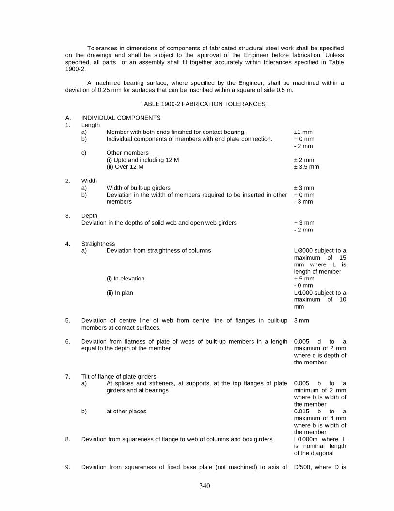
Tolerances in dimensions of components of fabricated structural steel work shall be specifiedon the drawings and shall be subject to the approval of the Engineer before fabrication. Unlessspecified, all parts of an assembly shall fit together accurately within tolerances specified in Table1900-2.
A machined bearing surface, where specified by the Engineer, shall be machined within adeviation of 0.25 mm for surfaces that can be inscribed within a square of side 0.5 m.
TABLE 1900-2 FABRICATION TOLERANCES .
A. INDIVIDUAL COMPONENTS1. Length
a) Member with both ends finished for contact bearing. ±1 mmb) Individual components of members with end plate connection. + 0 mm
- 2 mmc) Other members
(i) Upto and including 12 M ± 2 mm(ii) Over 12 M ± 3.5 mm
2. Widtha) Width of built-up girders ± 3 mmb) Deviation in the width of members required to be inserted in other
members+ 0 mm- 3 mm
3. DepthDeviation in the depths of solid web and open web girders + 3 mm
- 2 mm
4. Straightnessa) Deviation from straightness of columns L/3000 subject to a
maximum of 15mm where L islength of member
(i) In elevation + 5 mm- 0 mm
(ii) In plan L/1000 subject to amaximum of 10mm
5. Deviation of centre line of web from centre line of flanges in built-upmembers at contact surfaces.
3 mm
6. Deviation from flatness of plate of webs of built-up members in a lengthequal to the depth of the member
0.005 d to amaximum of 2 mmwhere d is depth ofthe member
7. Tilt of flange of plate girdersa) At splices and stiffeners, at supports, at the top flanges of plate
girders and at bearings0.005 b to aminimum of 2 mmwhere b is width ofthe member
b) at other places 0.015 b to amaximum of 4 mmwhere b is width ofthe member
8. Deviation from squareness of flange to web of columns and box girders L/1000m where Lis nominal lengthof the diagonal
9. Deviation from squareness of fixed base plate (not machined) to axis of D/500, where D is
column. This dimension shall be measured parallel to the longitudinal axis ofthe column at points where the outer surfaces of the column sections makecontact with the base plate.
the distance fromthe column axis tothe point underconsideration onthe base plate.
10. Deviation from squareness of machined ends to axes of columns D/1000, where D isas defined in 9above
11. Deviation from squarness of machined ends to axes of beams or girder D/1000, where D isas defined in 9above
12. Ends of members abuting all joints through cleats or end plates, permissibledeviation from squareness of ends.
1/600 of depth ofmember subject toa maximum of 1.5mm
1905. ERECTION1905.1. General
The provisions of this item shall apply to erection of steel bridge superstructures or mainmembers of bridge superstructures, composed of steel, which span between supports.
If the sub-structure and the superstructure are built under seperate contracts, the departmentwill provide the substructure. constructed to correct lines, dimensions and elevations properly finishedand will establish the lines and the elevation required for setting steel.
The Contractor shall erect the structural steel, remove the temporary construction, and do allthe work required to complete the construction included in the contract in accordance with the drawingsand the specifications and to the entire satisfaction of the Engineer.
1905.2. Organisation and EquipmentThe Contractor shall submit erection plans prepared by the fabricator, showing a method and
procedure of erection, compatible with the details of fabrication.
A detailed scheme must be prepared showing stage-wise activities, with complete drawingsand working phase-wise instructions. This should be based on detailed stage-wise calculation and takeinto account specifications and capacity of erection equipment machinery, tools, tackles to be used andtemporary working loads as per Codal provisions.
The scheme should be based on site conditions e.g. hydrology, rainfall, flood timings andintensity, soil and sub-soil conditions in the river bed and banks, maximum water depth, temperatureand climatic conditions and available working space, etc.
The scheme should indicate precisely the type of temporary fasteners to be used as also theminimum percentage of permanent fasteners to be fitted during the stage erection. The workingdrawings should give clearly the temporary jigs, fixtures, clamps, spacer supports, etc.
Unless otherwise provided in the contract, the contractor shall supply and erect all necessaryfalsework and staging and shall supply all labour, tools, erection plant and other materials necessary tocarry out the work complete in all respects.
The Contractor shall supply all rivets, bolts, nuts, washers, etc. required to complete erection atsite with an allowance for wastage, etc., of 12 V2 per cent of the net number of field rivets, bolts,washers required, or a minimum of five number of each item.
Service bolts and nuts, ordinary platters, washers and drifts for use in the erection of work shallbe supplied at 60 per cent (45 per cent bolts and 15 per cent drifts) of the number of field rivets perspan in each size (this includes wastage). A reduction in the quantities of service bolts, etc., mayhowever, be specified by the Engineer if more than one span of each type is ordered.
Prior to actual commencement of erection all equipment, machinery, tools, tackles, ropes, etc.need to be tested to ensure their efficient working. Frequent visual inspection is essential in vulnerableareas to detect displacements, distress, drainages, etc.
Deflection and vibratory tests shall be conducted in respect of supporting structures, launchingtruss as also the structure under erection and unusual observations reviewed; looseness of fittings areto be noted.
For welded structures, welders’ qualifications and skill are to be checked as per standardnorms. Non-destructive tests of joints as per designer’s directives are to be carried out.
Precision non-destructive testing instruments available in the market should be used for notingvarious important parameters of the structures frequently and systematic record is to be kept.
Safety requirements should conform to IS:7205, IS:7273 and IS:7269 as applicable and shouldbe a consideration of safely, economy and rapidity.
Erection work should start with complete resources mobilised as per latest approved drawingsand after a thorough survey of foundations and other related structural work. In case of work ofmagnitude, maximum mechanisation is to be adopted.
The structure should be divided into erectable modules as per the scheme. This should be pre-assembled in a suitable yard/platform and its matching with members of the adjacent module checkedby trial assembly before erection. The structure shall be set out to the required lines and levels. Thestocks and masses are to be carefully preserved. The steelwork should be erected, adjusted andcompleted in the required. position to the specified line and levels with sufficient drifts and bolts.Packing materials are to be available to maintain this condition. Organised "Quality Surveillance"checks need to be exercised frequently.
Before starting work, the Contractor shall obtain necessary approval of the Engineer as to themethod adopted for erection, the number and character of tools and plants. The approval of theEngineer shall not relieve the Contractor of his responsibility for the safety of his method or equipmentor from carrying out the work fully in accordance with the drawings and specifications.
During the progress of work, the Contractor shall have a competent Engineer or foreman incharge of the work, who shall be adequately experienced in steel erection and acceptable to theEngineer.
1905.3. Handling and Storing of MaterialsSuitable area for storage of structures and components shall be located near the site of work.
The access road should be free from water logging during the working period and the storage areashould be on levelled and firm ground.
The store should be provided with adequate handling equipments e.g road mobile crane,gantries, derricks, chain pulley blocks, winch of capacity as required. Stacking area should be plannedand have racks, stands sleeper, access tracks, etc., and properly lighted.
Storage should be planned to suit erection work sequence and avoid damage or distortion.Excessively rusted, bent or damaged steel shall be rejected. Methods of storage and handling steel,whether fabricated or not shall be subject to the approval of the Engineer.
Fabricated materials are to be stored with erection marks visible, such as not to come intocontact with earth surface or water and should be accessible to handling equipment.
Small fitting hand tools are to be kept in containers in covered stores. All materials,consumables, including raw steel or fabricated material shall be stored specification -wise and size-wiseabove the ground upon platforms, skids or other supports. It shall be kept free from dirt and otherforeign matter and shall be protected as far as possible from corrosion and distortion. The electrodesshall be stored specification - wise and shall be kept in dry warm condition in properly designed racks.The bolts, nuts, washers and other fasteners shall be stored on racks above the ground with protectiveoil coating in gunny bags. The paint shall be stored under cover in air-tight containers IS:7293 and
IS:7969 dealing with handling of materials and equipments for safe working should be followed. Safetynuts and bolts as directed are to be used while working. The Contractor shall be held responsible forloss or damage to any material paid for by the Department while in his care or for any damage to suchmaterial resulting from his work.
1905.4. FormworkThe formwork shall be properly designed, substantially built and maintained for all anticipated
loads. The Contractor, if required, shall submit plans for approval to the Engineer. Approval of theplans, however, shall not relieve the Contractor of his responsibility.
1905.5. Straightening Bent MaterialThe straightening of plates, angles and other shapes shall be done by methods not likely to
produce fracture or any injury. The metal shall not be heated unless permitted by the Engineer forspecial cases, when the heating shall not be to a temperature higher than that producing a dark “cherryred” colour, followed by as slow cooling as possible.
Following the straightening of a bend or buckle the surface shall be carefully investigated forevidence of fracture. Sharp kinks and bends may be the cause for rejection of material.
1905.6. Assembling SteelThe parts shall be accurately assembled as shown on the drawings and match marks shall be
followed. The material shall be carefully handled so that no parts will be bent, broken or otherwisedamaged.
Hammering which will injure or distort the members shall not be done. Eearing surface orsurfaces to be in permanent contact shall be cleaned, before the members are assembled. The trussspans shall be erected on blocking, so placed as to give the proper camber. The blocking shall be left inplace until the tendon chord splices are fully riveted and all other truss connections pinned and bolted.Rivets in splices of butt joints of compression members and rivets in railings shall not be driven until thespan has been swung.
All joint surface for bolted connections including bolts, nuts washers shall be free from scale,dirt, burrs, other foreign materials arid defects that would prevent solid seating of parts. The slope ofsurface of bolted parts in contact with bolt head and nut shall not exceed I in 20, plane normal to boltaxis, otherwise suitable tapered washer shall be used.
All fasteners shall have a washer under nut or bolt head whichever is turned in tightening.
Any connection to be riveted or bolted shall be secured in close contact with service bolts orwith a sufficient number of permanent bolts before the rivets are driven or before the connections arefinally bolted. Joints shall normally be made by filling not less than 50 per cent of holes with servicebolts and barrel drifts in the ratio 4:1. The service bolts are to be fully tightened up as soon as the jointis assembled. Connections to be made by close tolerance or barrel bolts shall be completed as soon aspracticable after assembly.
Any connection to be site welded shall be securely held in position by approved methods toensure accurate alignment, camber and elevation before welding is commenced.
The field riveting, welding, bolted and pin connection shall conform to the requirements ofClause 1904 as appropriate. The correction of minor misfits involving harmless amounts of reaming,cutting and chipping will be considered a legitimate part of erection. However, any error in the shopfabrication or deformation resulting from handling and transportation which prevent s proper assemblingand fitting up of parts by moderate use of drifts of by a moderate amount of reaming and slight chippingor cutting shall be reported immediately to the Engineer and his approval of the method of correctionobtained. The correction shall be made in the presence of the Engineer.
1905.7. Field Inspection1905.7.1. General
All materials, equipment and work of erection shall be subject to the inspection of the Engineerwho shall be provided with all facilities including labour and tools required at all reasonable times. Anywork found defective is liable to be rejected.
1905.7.2. No protective treatment shall be applied to the work until the appropriate inspection andtesting has been carried out. The stage inspection shall be carried out for all operations so as to ensurethe correctness of fabrication and good quality. Girder dimensions and camber shall not be finallychecked until all welding and healing operations are completed and the member has cooled to auniform temperature.
1905.7.3. Testing of material : Structural steel shall be tested for mechanical and chemical propertiesas per various IS codes as may be applicable and shall conform to requirements specified in IS:226,IS:2062, 15:11587, IS:1977, IS:8500 and IS:961, etc. Rivets, bolts, nuts, washers, weldingconsumables, steel forging, casting and stainless steel shall be tested for mechanical and chemicalproperties in the appropriate IS Code.
Rolling and cutting tolerance shall be as per IS: 1852. The thickness tolerance checkmeasurements for the plate and rolled sections shall be taken at not less than 15 mm from edge.
Laminations in plates shall be carried out by ultra-sonic testing or any other specified methods.
Steel work shall be inspected for surface defects and exposed edge laminations duringfabrication and blast cleaning. Significant edge laminations found shall be reported to the Engineer forhis decision.
Chipping, grinding, machining or ultrasonic testing shall be used to determine depth ofimperfection.
1905.7.4. Bolted connections : Bolts and bolted connection joints with high strength friction grip boltsshall be inspected and tested according to IS:4000. Rivets and riveted connection shall be inspectedand tested for compliance of codal requirements.
The firmness of joint shall be checked by 0.2 mm filler gauge, which shall not go inside underthe rivet head by more than 3 mm. There shall not be any gap between members to be riveted.
Driven rivets shall be checked with rivet testing hammer. When struck sharply on head withrivet testing hammer, rivet shall be free from movement and vibration.
All loose rivets and rivets with cracks, badly formed or deficient heads or with heads which areeccentric with shanks, shall be cut out and replaced.
The alignment of plates at all bolted splice joints and welded butt joints shall be checked forcompliance with codal requirements.
Testing of flame cut and sheared edges is to be done, where the hardness criteria given in thecode are adopted. Hardness testing shall be carried out on six specimens.
1905.7.5. Welding and welding consumables : Welding procedure, welded connection and testing shallbe in compliance with codal requirements. All facilities necessary for stage inspection during weldingand on completion shall be provided to the Engineer or their inspecting Authority by manufacturer.
Adequate means of identification either by identification mark or other record shall be providedto enable each weld to be traced to the welder(s) by whom it was carried out.
All metal arc welding shall be’ in compliance with IS:9595 provisions.
The method of inspection shall be in accordance with IS: 822 and extent of inspection andtesting shall be in accordance with the relevant standards or in the absence of such a standard, asagreed with the Engineer.
Procedure testsThe Destructive and Non-Destructive test of weld all be carried out cording to IS:7307 (Part I).
Non-Destructive Testing of WeldsOne or more of the following methods may be applied for inspection or testing of weld:
(i) Visual Inspection : All welds shall be visually inspected, which should cover all defects of weldsuch as size, porosity, crack in the weld or in the HAZ (Heat Affected Zone) etc. Suitablemagnifying glass may be used for sual inspection. A weld shall be acceptable by visualinspection if it that :a) The weld has no cracks.b) Through fusion exists between weld arid base metal and between adjacent layers of weldmetal.c) Weld profiles art in accordance with requisite clauses of IS:9595 or as seed with theEngineer.d) The weld shall be of full cross section, except for the ends of intermittent fillet welds outsidetheir effective length.e) When weld is transverse to the primary stress, undercut shall not be more than 0.25 mmdeep in the part of that is undercut and shall not be more than 0.8 mm deep when the weld isparallel to the primary stress in the part that is undercut.f) The fillet weld in any single continuous weld shall be permitted to under run the nominal filletweld size specified by 1.6 mm without correction provided that undersize portion of the welddoes not exceed 10 per cent of the length of the weld. On the web-to-flange welds on girders,no under- run is permitted at the ends for a length equal to twice the width of the flange.g) The piping porosity in fillet welds shall not exceed one in each 100 mm of weld length andthe maximum diameter shall not exceed 2.4 mm except for fillet welds connecting stiffeners toweb where the sum of diameters of piping porosity shall not exceed 9.5 mm in any 25 mmlength of weld and shall not exceed 19 mm in any 3020 mm length of weld.h) The full penetration groove weld in butt joints transverse to the direction of computedtensile stress shall have no piping porosity. For all other groove welds, the piping porosity shallnot exceed one in 100 mm of length and the maximum diameter shall not exceed 2.4 mm.
(ii) Magnetic Particle and Radiographic Inspection: Welds that are subject to radio- graphic ormagnetic particle testing in addition to visual inspection shall have no crack. Magnetic particletest shall be carried out for detection of crack and other discontinuity in the weld according toIS:5334. Radiographic test shall be carried out for detection of internal flaws in the weld suchas crack, piping porosity inclusion, lack of fusion, incomplete penetration, etc. This test mat becarried out as per IS:1182 and 15:4853. Acceptance Criteria: The weld shall be unacceptable ifradiographic or magnetic particle testing shows any of the type of discontinuities indicated inthe code.
(iii) Ultrasonic Inspection : The Ultrasonic testing in addition to visual inspection shall be carried outfor detection of internal flaws in the weld such as cracks, piping porosity inclusion, lack offusion, incomplete penetration, etc Acceptance criteria shall be as per IS:4260 or any otherrelevant IS Specification and as agreed to by the Engineer.
iv) Liquid Penetration Inspection : The liquid penetrant test shall be carried out for detection ofsurface defect in the weld, as per 15:3658, in addition to visual inspection.The non-destructive testing of following welds be carried out using one of the method ormethods described at (ii).(iii) and (iv) above, as may be agreed to by the Engineer.a) All transverse butt welds in tension flangeb) 10 per cent of the length of longitudinal and transverse butt welds in tension flanges.c) 5 per cent of the length of longitudinal and transverse butt welds in compression flanges.d) All transverse butt welds in webs adjacent to tension flanges as specified by the Engineer.
The particular length of welds in webs to be tested shall be agreed with the Engineer, in case of(b) or (c). Where specified by the Engineer, bearing stiffeners or bearing diaphragms adjacent to welds,flange plates adjacent to web/flange welds, plates at cruciform welds, plates in box girder constructionadjacent to corner welds or other details shall be ultrasonically tested after fabrication. Any lamination,lamellar tearing or other defect found shall be recorded and reported to Engineer for his decision.
Testing of Welding for Cast Steel : The testing of weld for cast steel shall be carried out as maybe agreed to by the Engineer.
Stud Shear Connectors : Stud shear connectors shall be subjected to the following tests :a) The fixing of studs after being welded in position shall be tested by striking the side of the head
of the stud with a 2 kg hammer to the satisfaction of the Engineer.b) The selected stud head stroked with 6 kg hammer shall be capable of lateral displacement of
approximately 0.25 the height of the stud from its original position.
The stud weld shall not show any sign of crack or lack of fusion.
The studs whose welds have failed the tests given in (a) and (b) shall be replaced.
1905.7.6. Inspection requirement : The fabricated member/component made out of rolled and built-upsection shall be checked for compliance of the tolerances given in Table 1900-2. Inspection ofmember/components for compliance with tolerances, and the check for deviations shall be made overthe full length.
During checking, the inspection requirement shall be placed in such a manner that local surfaceirregularities do not influence the results. For plate, out-of-plane deviation shall be checked at rightangle to the surface over the full area of plate.
The relative cross-girder or cross frame deviation shall be checked over the middle third oflength of the cross girder or frame between each pair of webs and for cantilever at the end of member.
The web of rolled beam or channel section shall be checked for out-of-plane deviation inlongitudinal direction equal to the depth of the section.
During inspection, the component/member shall not have any load or external restraint.Inspection Stages : The inspection to be carried out for compliance of tolerances shall include
but not be limited to the following stages:a) For completed pans, component/members on completion of fabrication and before any
subsequent operation such as surface preparation, painting, transportation, erection.b) For webs of plate and box girder, longitudinal compression flange stiffeners in box girder ? and
orthotropic decks and all web stiffeners at site joints, on completion of site joint.c) For cross girders and frames, cantilevers in orthotropic decks and other parts in which
deviations have apparently increased on completion of site assembly.
Where, on checking member/component for the deviations in respect of out-of-plane or out-of-straightness at right angles to the plate surface, and any other instances, exceed tolerance, themaximum deviation shall be measured and recorded. The recorded measurements shaft be submittedto the Engineer who will determine whether the component/member may be accepted withoutrectification, with rectification or rejected.
1906. PAINTING1906.1. General
Unless otherwise specified, all metal work shall be given approved shop coats as well as fieldcoats of painting. The item of work shall include preparation of metal surfaces, application of protectivecovering and drying of the paint coatings and supply of all tools, scaffolding, labour and materialsnecessary. Coatings shall be applied only to dry surfaces and the coated surfaces shall not be exposedto rain or frost before they are dry. The coatings shall be applied to all surfaces excluding shearconnectorsand inner surfaces of fully sealed hollow sections. Care shall be taken during coating of adjacentsurfaces to build up primer on the shear connectors.
1906.1.1. Types of paints(i) Ordinary Paints
These include paints based on drying oils, alkyd resin, modified alkyd resin, phenolic varnishepoxy, etc. Alkyd resin paints for the protection of steel structures are based partly on natural oils andpartly on synthetic resins. These paints shall be used for steel structures in atmospheres which are nottoo aggressive. Oil based paints can be used for steel structures in cases where the surfacepreparation cannot be ideal. Ordinary painting can generally be sub-divided into two groups :a) Primary Coats
This shall be applied immediately after the surface preparation and should have the propertiesof adhesion, corrosion inhibition and imperviousness to water and air.
b) Finishing CoatsThese are applied over the primary coat and should have the properties of durability, abrasion
resistance, aesthetic appearance and smooth finish.
(ii) Chemical Resistant PaintsThe more highly corrosion resistant paints can be divided into two main groups:a) One pack paints (ready for use)b) Two pack paints (mixed before use)
The two pack paints shall be mixed together immediately before use since they are workablethereafter only for a restricted period of time and dry up as a result of a reaction between theircomponents and yield hard tough films with resistance to abrasion.
(iii) Vinyl PaintsThese are based on polyvinyl resins such as polyvinyl-chloride (PVC) and polyvinyl-acetate,
etc. Certain types of vinyl resin paints yield thick, relatively soft andrubber like coatings with good chemical resistance. They can be repainted without difficulty.
(iv) Chlorinated Rubber PaintsThese paints also have good chemical resistance. The main fields of applications shall be in
aggressive environments. In general, chlorinated rubber paints do not have a high gloss.
(v) Bituminous PaintsAs a paint vehicle, bituminous is inferior, but because of the low price, this should be applied in
greater thickness (upto several millimetres) and may be suitable for some situations. A significantadvantage of bitumen paints is their impermeability to ingress of water. However, bituminous paints donot withstand effectively detrimental effects of oil.
(vi) Epoxy PaintsThese resin paints have good adherence to a well prepared sub-strata. They are mechanically
strong and resistant to chemicals, A disadvantage of epoxy resin paints is that it can rapidly becomedull when exposed to strong sunlight. These disadvantages do not, however, greatly influence theirprotective power,
(vii) Polyurethane PaintsThe chemical and mechanical behaviour of polyurethane paint resembles those of epoxy paint
very much. However, polyurethane paint retains its gloss for a longer period. Because of the high priceof polyurethane paint, a combination of the two viz., polyurethane and epoxy paints may sometimes beused.
(viii) Zinc Rich PaintsInstead of introducing an inhibitive pigment into paint, metallic zinc can be used and such
paints can provide cathodic protection to steel.
1906.1.2. Surfaces which are inaccessible for cleaning and painting after fabrication shall be painted asspecified before being assembled for riveting.
All rivets, bolts, nuts, washers etc., are to be thoroughly cleaned and dipped into boiling linseedoil conforming to IS:77. All machined surfaces are to be well coated with a mixture of white leadconforming to IS:34 and Mutton Tallow conforming to IS:887.
For site paintings, the whole of the steel work shall be given the second cover coat after finalpassing and after touching up the primer and cover coats, if damaged in transit.
1906.1.3. Choice of painting systemThe choice of suitable painting system is dependent on factors such as:
- Available application methods viz. brush, roller or spray- Durability in a specific environment- Availability of skilled manpower- Cost / benefit etc.
It is therefore necessary to consult various manufacturers of paint and ascertain the aboveaspects while deciding on the appropriate choice of painting system.

1906.1.4. Quality of paint : The paints which have been tested for the following qualities as per thespecifications given in the relevant IS codes should only be used :- Weight Test (weight per 10 litre of paint thoroughly mixed)- Drying time- Flexibility and Adhesion- Consistency- Dry thickness and rate of consumption
1906.1.5. Unless otherwise specified, all painting and protective coating work shall be done inaccordance with IS: 1477 (Part 1).
1906.2. Surface PreparationSteel surface to be painted either at the fabricating shop or at the site of work shall be prepared in athorough manner with a view to ensuring complete removal of mill scale by one of the followingprocesses as agreed to between the fabricator and the Engineer :a) Dry or wet grit / Sand blastingb) Pickling which should be restricted to single plates, bars and sectionsc) Flame cleaning
Primary coat shall be applied as soon as practicable after cleaning and in case of flamecleaning, primary coat shall be applied while He metal is still warm. All slag from welds shall beremoved before painting. Surfaces shall be maintained dry and free from din and oil. Work out of doorsin frosty or humid weather shall be avoided.
1906.3. CoatingsPrime coat to be used shall conform to the specification of primers approved by the Engineer.
Metal coatings shall be regarded as priming coatings. Primer shall be applied to the blast cleanedsurface before any deterioration of the surface is visible. In any case, the surface shall receive one coatof primer within 4 hours of abrasive blast cleaning. All coats shall be compatible with each other, Whenmetal coat-ings are used, the undercoat shall be compatible with the metal concerned. The undercoatand finishing coal shall preferably be fromthe same manufacturer. Successive coats of paints shall beof different shades or colours and each shall be allowed to dry thoroughly before the next is applied.Particular care shall be taken with the priming and painting of edges, corners, welds and rivets. Typicalguidelines for epoxy based paints and the convent ional painting system for bridge girders as givenbelow may be complied with:a) Epoxy Based Paintingi) Surface preparation: Remove oil/grease by use of petroleum hydrocarbon solution (15:1745)
and Gr it blasting to near while metal surface.ii) Paint system; 2 coals of epoxy zinc phosphate primer = 60 micron; Total 5 coats = 200 micronb) Conventional Painting System for areas where corrosion is not severe
Priming Coat :One heavy coal or ready mixed paint, red lead primer conforming to IS: 102 or One coat of
ready mixed zinc chrome primer conforming to IS: 104 followed by one coat of ready mixed red oxidezinc chrome primer conforming to IS:2074. or Two coats of zinc chromates red oxide primer conformingto IS: 2074
Finishing Coats :Two cover coats of red oxide paint conforming to IS: 123 or any other approved paint shall be
applied over the primer coat. One coat shall be applied before the fabricated steel work leaves the shop. After the steel work is erected at site, the second coat shall be given after touching up the primerand the cover coats if damaged in trans it.
c) Conventional Painting System for areas where corrosion is severe
Priming Coat :Two coats of ready mixed red lead primer conforming to IS: 102 or One coat of ready mixed
zinc chrome primer conforming to IS: 104 followed by one coal of zinc chromate conforming oxideprimer to IS:2074.
Finishing Coats :
Two coats of aluminum paint conforming to 1S:2339 shall be applied over the primer coat Onecoat s hall be applied before the fabricated steel work leaves the s hop. After the steel work is erectedat site, the second coat s hall be given after touching up the primer and the cover coats if damaged intransit.
1906.4. Painting in the ShopAll fabricated steel shall be painted in the shops after inspection and acceptance with at least
one priming coat, unless the exposed surfaces are subsequently to be cleaned at site or are metalcoated. No primer s hall be applied to galvanized surfaces. Shop contact surfaces, if specificallyrequired to be painted, shallbe brought together while the paint is still wet. Field contact surfaces and surfaces to be in contact withcement shall be painted with primer only. No paint shall be applied within 50mm of designed location offield welds. Paint shall be completely dried before loading and transporting to site.
Surface not in contact but inaccessible after shop assembly shall receive the fully specifiedprotective treatment before assembly. Where surfaces are to be welded, the steel shall not be paintedor metal coated within a suitable distance from any edges to be welded if the specified paint or metalcoating would be harmful to welders or is expected to impair the quality of site welds. Exposedmachined surfaces shall be adequately protected.
1906.5. Painting at SiteSurfaces which will be inaccessible after site assembly shall receive the full specified protective
treatment before assembly. Surfaces which will be in con tact after site assembly shall receive a coat ofpaint (in addition to any shop priming) and shall be brought together while the paint is still wet.
Damaged or deteriorated paint surfaces shall be first made good with the same type of coat asthe shop coat. Where steel has received a metal coating in the shop, this coating shall be completed onsite so as to be continuous over any welds, bolts and site rivets.
Specified protective treatment shall be completed after erection.
1906.6. Methods of ApplicationThe methods of application of all paint coatings shall be in accordance with the manufacturer’s
written recommendation and shall be as approved by the Engineer. Spray painting may be permittedprovided it will not cause inconvenience to the public and is appropriate to the type of structure beingcoated. Areas hard to gain access tofor painting and areas shaded for spray application shall be coated first by brushing. Oil based red leadprimers must be applied by brush only, taking care to work into all corners and crevices.
The primer, intermediate and finishing coats shall all be applied so as to provide smoothcoatings of uniform thickness. Wrinkled or blistered coatings or coatings with pinholes, sags, lumps orother blemishes shall not be accepted. Where the Engineer so directs, the coating shall be removed byabrasive blast cleaning and replaced at the Contractor’s expense.
1906.7. Guideline of Specifications for Protective Coating System in Different Environments Since theseriousness of the problem of corrosion depends upon atmospheric conditions and these varyenormously, there is no single protective system or method of application that is suitable for everysituation.
However, as a guide, broad recommendations are given in Table 1900-3 for various types ofcoatings in various environmental conditions which should be complied with. Approximate life to firstmaintenance is also indicated and can be us ed as a guide.
TABLE 1900-3 : RECOMMENDATIONS FOR TYPES OF PROTECTIVE COATINGS
System Environmenti) Wire brush to remove all loose rust and
scale; 2 coats drying oil type 1 under coatalkyd type paint; 1 finishing coat alkydtype. Total dry film thickness = 150 µm
Suitable for mi ld conditions whereappearance is of some importance andwhere regular maintenance is intended. Thissystem may deteriorate to a marked extent ifit is exposed to moderate aggressive
atmospheric conditions for lengthy period.
ii) Wire brush to remove all loose rust andscale; 2 coats drying oil type primer. 2under coats micaceous iron oxide (MXO)pigmented phenolic modified drying oil.Total dry film thickness = 170 µm
Similarly to (i) but where appearance is notvery important provides longer life in mildcondition. Will provide upto 5 years life to firstmaintenance in polluted inland environment
iii) Blest clean the surface; 2 coats of quickdrying primer, undercoat alkyd type paint;1 finishing coat alkyd type. Total dry filmthickness:130 – 150 µm
Compared to (i), this would provide a longerlife in mild conditions and could be used inless mild situation e.g., inland polluted, wheremaintenance could easily be carried out atregular intervals
iv) Blast clean the surface; 2 coats of dryingtype oil primer, 1 undercoat micaceousiron oxide pigmented drying oil type paint.Total dry filmthickness : 165 - 190 µm
suitable for general structural steel workexposed to ordinary polluted inlandenvironments where appearance is not ofprimary importance.
v) Blast clean the surface; 2 coats of metalliclead pigmented chlorinated rubber primer,1 undercoat of high build chlorinatedrubber; I finishing coal of chlorinatedrubber. Total dryfilm thickness : 200 µm
Suitable for structures in reasonablyaggressive conditions e.g. near the coast,Will provide long-term protection than (iv) innon-coastal situations. Also suitable foraggressive interior situation such asindustrial areas.
vi) Blast clean the surface; 350 - 450 µmthickness. coal tar epoxy.
Suitable for sea water splash zones or forconditions of occurrence of frequent saltsprays.
vii) Pickle; hot dip galvanized (Zinc). Totalthickness : 85 nm
Suitable for steel work in reasonably mildconditions Life of 15-20 yean before firstmaintenance could be expected in manysituations
viii) Grit blast, hot dip galvanised. (Zinc). Totalthickness = 140 µm
Provides a longer life than (vii) because ofthicker zinc coating
ix) Grit blast; I coat of sprayed zinc/ aluminumfollowed by suitable sealer Total thickness= 150 µm
Expected to provide long term protectionapprox 15-20 years in aggressiveatmosphere
1907. TESTS AND STANDARDS OF ACCEPTANCEThe materials-shall be tested in accordance with relevant IS specifications and necessary test
certificates shall be furnished. Additional tests, if required, shall be got carried out by the Contractor athis own cost.
The fabrication, furnishing, erecting, painting of structural steel work shall be in accordance withthese specifications and shall be checked and accepted by the Engineer.
1908. MEASUREMENTS FOR PAYMENTThe measurements of this item shall be in tonnes based on the net weight of metal in the
fabricated structure computed on the basis of nominal weight of materials.
The weight of rolled and cast steel and cast iron shall be determined from the dimensionsshown on the drawings on the following basis :
Rolled or cast steel : 7.84 X 10⁻³ kg/cu. cm.Cast Iron : 7.21 x 10⁻³ kg/cu. cm.
Weight of structural secti ons shall be nominal weight
Weight of castings shall be computed from the dimensions shown on the drawings with anaddition of 5 per cent for fillets and over-runs.
Weight of weld fillets ’and the weight of protective coatings shall not be included.
Weight of rivet heads s hall be computed by taking the weight of 100 s nap heads as given inTable 1900-4.
When specially agreed upon, allowance for snap heads may be taken as a flat percentage ofthe total weight. This percentage may be taken as 3 per cent or modified by mutual agreement.
TABLE 1900-4 : WEIGHT OF RIVET HEADS
Dia of Rivet as manufactured mm Weight of 100 snap heads kg12 1.314 2.116 3.418 4.4520 6.122 8.124 10.527 15.030 20.533 27.2
The Contractor shall supply detailed calculation sheets for the weight of the metal in thefabricated structure.
No additions s hall be made for the weight of protective coating or weld fillets.
Where computed weight forms the basis for payment, the weight shall be calculated for exactcut sizes of members used in the structure, deductions being made for all cuts, except for rivet holes .Additions shall be made for the rivet heads as mentioned above.
When specially agreed upon, the bas is for payment may be the bridge weight complete,according to specifications included in special provisions of the Contract.
1909. RATEThe contract unit rate for the completed structural steel work shall include the cost of all materials,labour, tools, plant and equipment required for fabrication, connections, oiling, painting, temporaryerection, inspection, tests and complete final erection as shown on the drawings and as specified inthese Specifications.


CONTENT
Clause No Description2001 DESCRIPTION
2002 GENERAL
2003 STEEL BEARINGS
2004 SPECIAL BEARINGS
2005 ELASTOMERIC BEARINGS
2006 POT BEARINGS
2007 INSPECTION AND TESTING
2008 TESTS AND STANDARDS OF ACCEPTANCE
2009 MEASUREMENTS FOR PAYMENT
2010 RATE
2001. DESCRIPTION
This work shall consist of furnishing and fixing bearings in position in accordance with the details shownon the drawings, to the requirements of these specifications or as directed by the Engineer.
2002. GENERAL
i) Bearing plates, bars, rockers, assemblies and other expansion or fixed devices shall be constructedin accordance with the details shown on the drawings.
ii) The bearings may cither be supplied directly to the Engineer by the manufacturer to be installed bythe Contractor or the Contractor is 10 supplies and install the bearings as part of the contract. In theformer case, the manufacturer shall be associated with the installation of the bearings to the fullsatisfaction of the Engineer, whereas in the latter case, the Contractor shall be solely responsiblefor the satisfactory supply and installation of the bearing. In the detailed description of thespecification, a general reference shall be made to the Contractor or manufacturer and theinterpretation shall be as per terms of contract.
iii) The Contractor shall exercise the utmost care in setting and fixing all bearings in their correctpositions and ensuring that uniformity is obtained on all bearing surfaces,
iv) Bearings shall be handled with care and stored under cover.
v) When bearing assemblies or plates art shown on the drawings 10 be placed (not embedded)directly on concrete, the concrete bearing area shall be constructed slightly above grade (notexceeding 12 mm) and shall be finished by grinding.
vi) It shall be ensured that the bearings are set truly level and in exact position as indicated on thedrawings so as to have full and even bearing on the seats. Thin mortar pads (not exceeding 12mm) may even be made w meet with this requirement.
vii) It shall be ensured that the bottoms of girders to be received on the bearings are plane at thelocations of these bearings and care shall be taken that the bearings are not displaced whileplacing the girders.
viii) M.S. bearings sliding on M.S. Plates shall not be permitted. For sliding plate bearings stainless,steel surface sliding on stainless steel plate with mild steel matrix shall be used. The other optionshall be to provide PTFE surface sliding on stainless steel.
ix) Some types of bearings which have been successfully used in various bridges in India have beencovered by these Specifications. For innovative types of structures or in special cases, specialtypes of bearings to suit the requirements may have to be provided for which special specificationsmay be laid down by the Engineer.
2003. STEEL BEARINGS
2003.1. MaterialsThe material for steel bearings shall conform to the requirement of Section 1000. Some additionalrequirements for materials for steel bearings are indicated below:
a) Railway axles (R 19) are also acceptable as forged steel for rollers.
b) For the purpose of checking the soundness of cast steel components, castings shall be ultrasonicallyexamined following procedures as per 1S:7666 with acceptance standard as per IS: 9565. Thecastings may also be checked by any other accepted method of non-destructive testing asspecified in 15:1030. Quality level of castings shall be level 3 as per IS: 9565.
The grease for bearings shall conform to the requirements of IS: 503 (Grade 4).
2003.2. Construction Operations
a) All work shall conform strictly lo the drawings and shall be in accordance with the provisions of thissection. Care shall be taken lo ensure that all parts of an assembly fit accurately together. Theworkmanship shall satisfy all relevant provisions laid down in Section 1900.
b) Knuckle pins, rolling surf aces of the rollers and bearing surface of the bearing plates shall bemachined and all boll holes shall be drilled. The whole bearings shall be fitted and finished asrequired for good quality machined work to the satisfaction of the Engineer. However, in case ofbearings which arc to be grouted or bedded on a suitable yielding material on any surface which isto be in permanent contract with the grout or the yielding material may be left unmachined.
c) In prestressed concrete construction where launching of girders is employed, in order to avoidslipping or jumping of rollers due lo vibration or jolts, adequate measures may be taken to ensurethat the roller assembly is not disturbed. It is normal practice lo provide rocker bearings on thebunching end and place the beam on Iris rocker end slightly in advance of placing on the roller.
d) During concreting of girders, the bearings shall he held in position securely by providing temporaryconnection between the top and bottom plates in cast of fined bearings and between top plate,base plate and saddle plate in case of roller cum-rocker bearing or by any other suitablearrangement which prevents the relative displacement of the components.
e) In prestressed precast girders, where recesses arc left on the underside of girders receive theanchor bolts, grout holes extending to the beam sides or to the deck level shall be provided. Thecement sand grout shall have a mix of 1. 1
2003.3. Workmanshipa) Fabrication shall be carried out by an organization experienced and qualified in undertake precision
engineering of this type and be approved by the Engineer
b) Workmanship shall be of good quality, neatly finished and of good appearance
c) Castings shall be true to the forms and dimensions shown on the drawings and stall be free frompouring faults, sponginess, cracks, blow holts and other defeat on position, affecting theirappearance or strength Warped or distorted castings will not be accepted. Exposed surfaces shallbe smooth and dense.
d) All castings shall be cleaned by sand or shot blasting to remove sand or scale and to present toclean uniform surface.
e) All irregularities fins or risers shall be ground off flush with the adjacent surface. Castings withvisible cracks, blow holes or similar blemishes shall be rejected if the imperfections are located inbearing surface or cannot be remedied to the approval of the Engineer.
f) Imperfections which are not located in bearing surface shall be cleaned out, filled with weld metal ofthe appropriate composition and ground flush.
g) All surfaces of major components like top plates, saddle plates, base plates, rollers of the bearingsshall be machined all over for correct alignment, interchangeability, proper fittings, etc.
2003.4. Tolerances
Tolerances for its individual components or of the assembled bearings shall be as shown on thedrawings or subject to the approval of the Engineer.Unless otherwise specified, the following tolerances shall be maintained:
Diameter of Rollers, Knuckle Pins and BoresTolerances on diameter of rollers and all convex surfaces s hall conform lo K7 of 15:919.Tolerances on diameter of all concave surfaces shall conform 10 D8 of IS: 919.
Height of Bearings
Tolerances on height of any component casting shall not exceed +0.5 mm. No minus tolerance s hallbe allowed. The edges of all ribs shall be parallel throughout their length.Base PlateTolerance on length and width of the base plate shall not exceed +1.0 mm, tolerance on the thicknessof the plate s hall not exceed +0.5 mm. No minus tolerance shall be allowed. All rocking, rolling andsliding surfaces shall have a machine smooth finish to 20 micron maximum mean deviation as perIS:3073.
CastingsNo minus tolerance shall be allowed in the thickness of any of the castings. The edges of all ribs shallbe parallel throughout their length.
2003.5. Installation of Steel Bearings2003.5.1. General
a) Bearings shall be placed in the positions as shown on the drawings with all bearing surfaces in fullcontact and to the tolerances as specified.
b) Roller and rocker bearings shall be placed so that their axles of rotations arc horizontal and normallo the direction of movement of the members they support. Upper and tower bearing plates shall beset horizontal in both directions.
c) During installation the bearings shall be pre-set with respect to the bearing axis to account for themovement due to the following:
i) Temperature variation between the average temperature prevailing at the time of installation andthe mean design temperature.
ii) Shrinkage, creep and elastic shortening,
d) For bridges in gradient, the bearing plates shall be placed in a horizontal plane.
2003.5.2. Placing
a) On supporting structures, pockets shall be provided to receive anchor bolts; one side of the pocketshall project beyond the bearing plate The pocket shall be Tilted with mortar of mil 1:1 and theconcrete bearing area also shall be finished level by a thin and stiff mortar pad of mix 1:1 (thethickness not exceeding 12mm) just before placing of bearing assemblies or bottom plate on theconcrete seat.
b) In case of precast girders a recess of 6 mm shall be provided on the underside with a level finish forhousing the bearing plate. A thin and stiff mortar pad of mi* 1:1 with thickness not exceeding 3 mmshall be provided over the top plate before lowering the precast beam in position in order to ensurefull and even pressure on the plate surface.
c) It shall be ensured that while placing the girders, the bearings are in their exact positions asindicated on the approved drawing and not displaced there from.
d) All concrete surfaces to be in contact with the mortar shall be thoroughly cleaned and keptsaturated with water for a period not less than 24 hours before placing mortar and operations are tobe carried out when the surface temperatures of the exposed bearings are the minimum practical.
e) No mortar that is more than 30 minutes old after completion of mixing, shall be used,
f) After placing and finishing the mor tar, the bearing shall be checked for position and shims or othertemporary supports removed and the mortar made good. If the bearing has moved, it or the plateshall be lifted, the mortar removed and the whole procedure repeated,
g) Exposed faces of the mortar shall be cured under damp Hessi an for 7 days.
h) Placing of the bearing and mortar shall only be carried out in the presence of the Engineer.
2003.5.3. Checking, cleaning and lubrication:
Before erection, each bearing shall be uncrated, disassembled and checked. Any damaged parts shallbe made good for approval.All bearings with sliding surfaces shall be cleaned and lightly lubricated with an approved lubricantimmediately before erection.
2003.5.4. Testing
i) The materials to be used in the bearing) shall conform to the specifications laid down in clause2003.1.
ii) If required, a suitable number of complete bearings as specified by an accepting authority shall betested lo 1.25 times the design load. Recovery should be 100 per cent. Contact surfaces shall beexamined by illumination source for any defects, cracks, etc. Segmental rollers shall be tested fordesign movements.
iii) For large lots (consisting of 1:2 jets or more), a quality control report shall be submitted as detailedbelow:
a) Unless otherwise agreed upon by the Engineer and the manufacturer, the latter shall furnish acomplete report on the process of quality control. The Engineer may appoint an authorizedinspection agency for inspection purpose on his behalf. Such an inspection agency shall alsosubmit reports to the Engineer regarding various tests performed on the bearing or certify theacceptance of the bearings.
b) Test certificates of all raw materials shall be submitted. If manufacturer’s lest certif icates ire notavailable for the raw materials, the bearings manufacturer shall perform the necessary confirmatorytests as per relevant codes of practice and shall furnish the test results.
c) A detailed quality control system including stage by stage inspection, starting from raw materials upto the finished bearing shall be submitted by the bearing manufacturer.
d) The Engineer shall reserve the right lo witness such inspection al manufacturer’s works with orwithout prior permission of the manufacturer. For this, the bearing manufacturer shall have in-planttesting facilities as far as possible and practicable.
e) The bearing manufacturer shall maintain a list of consumption of raw material for a period of at leastprevious one year.
f) Test certificates of bearings manufactured during preceding one year shall be made available at themanufacturer’s works.
g) In case the lot size of similar bearings exceeds 12 sets as per the direction of the Engineer, oneextra set of bearings for each 24 sets of bearings or pan thereof. Shall be manufactured and thecost of such extra bearings shall be borne by the user.
h) The Engineer shall select the extra bearing(s) at random mid hall perform various tests includingdestructive testing on h al his discretion, either, 11 the manufacturer’s works or al any otherapproved test laboratory, notwithstanding the lest reports submitted.
i) In case there is a major discrepancy regarding material, the engineer shall declare the whole lot ofbearings as unacceptable,
j) In case minor defects in fabrication, like welding or machining, is found in the test bearing beforedestructive testing and if the test bearing is found to be acceptable after destructive testing, theminor defects in the test bearings shall not be a bar to the acceptance of the entire lot.
k) The opinion of the Engineer in cases (i) and (j) above shall be binding on the manufacturer.
2004. SPECIAL BEARINGS
2004.1. Spherical BearingThis bearing only takes care of vertical load and horizontal force due to sliding friction. The bearing willpermit aniaxial translatory movement along longitudinal axis of the bridge and rotation along all axes.The bearing shall consist of the following parts:
Bottom Plate
A bottom plate with concave surface is integrally cast on circular square plate. The bottom plate isconnected to the substructure by means of tight fitted anchor bolls, which are embedded in concrete.The material of bottom plate shall be cast steel.Pure unfilled quality dimpled PTFE of specified thickness shall be provided on top of concave surface ofbottom plate in order to allow smooth rotation.
Saddle Plate
A saddle plate with square/circular/rectangular top and convex surface at bottom shall be placed in theconcave surface of bottom plate. The radius of curvature of the convex bottom of the saddle plate shallbe slightly less than that of the concave top surface of the bottom plate to ensure sufficient contact overa small area. Rotation along all axes shall be permitted along the contact surface of the saddle plateand the bottom plate. Pure unfilled quality dimpled PTFE sheet shall be recessed to specified depth ofrecess over the top of saddle plate. Suitable elastomeric seal shall be provided on the saddle plate toprevent ingress of dirt and moisture. The material of saddle plate shall be cast steel.
Top PlateThe top plate shall have stainless steel plate welded to its bottom which shall slide over PTFE. Theassembly shall be connected to the superstructure by tight fitted anchor bolts, Translatory movementsalong longitudinal axis of bridge shall be accommodated at the FIFE/ Stainless steel sliding surface.The material of top plate shall be cast steel.
Guide PlateGuide Plates shall be welded to saddle plate so as to permit only longitudinal movement. The materialof guide plates should be cast steel.
2004.2. Pin BearingPin bearing shall ensure fixity by arresting translatory movement. The pin bearing shall not take anyvertical load. It will take care of the longitudinal horizontal force of the entire superstructure unit as wellas transverse horizontal force developed at the fixed end.A pin bearing shall consist of a short height structural built-up column embedded in pier cap and theprotruding length inside soffit of deck shall have rocker plates on ail four sides, which permit rotation.Pin bearing shall resist horizontal force from any direction and will permit rotation but will not bear anyvertical load. The material of pin bearing including rocker plates shall be high tensile steel conforming toIS: 961.
2004.3. In general the sliding spherical and pin bearing shall conform to BS: 5400, Parts 9.1 and 9.2and all relevant clauses of this specification. Bearings shall be guaranteed for design loads andmovements. The term bearing shall include the entire assembly covering all the accessories requiredfor operation, erection and dismantling for replacement. All bearings shall be of replaceable type. Thesebearings should be based on their design to the specifications mentioned/international specifications.The manufacturer should gel their design approved from appropriate authority and the manufacturershould be associated with installation of bearings,
2004.4. MaterialsAll materials, particularly the following, shall be original, unused or non-re-cycled conforming to relevantspecifications:- Cast Steel; Mild Steel, Stainless Steel shall conform to Clause 2003.1.- Copolymer Poly Tetra Fluora Ethylene (FIFE) unfilled quality "shall have required properties as per
BS: 5400 and thickness shall be as specified.- Anchor Bolls shall be as per relevant IS specifications.
2004.5. Seating of Pin Bearing
i) Backing plate with studs welded on the face opposite to the seating of manufacture shill bedelivered by the manufacturer.
ii) This backing plate shall be accurately positioned on the reinforcement grid of the pedestal andlevelled.
iii) Studs shall be tacit welded/tied to the reinforcement to keep the backing plate in proper locationduring casting.
iv) Depth of embedment of the backing plate in the concrete shall be as per relevant drawing.v) The round base of the pot (bottom) of the pin bearing assembly shall be connected to the backing
plates by anchor screws after concreting of pier cap pedestal.vi) In order to ensure successful transfer of large horizontal forces to be resisted by the Pin bearing,
great care shall be taken in detailing the reinforcement in the sub-structure and the super-structureadjacent to the studs in the backing plate,
2004.6. Acceptance Test on Spherical Bearings
1. AH bearings shall be checked for overall dimensions2. All bearings shall be load tested to 1.25 times design vertical load3. A pair of bearings selected at random shall undergo testing in order lo determine coefficient of
friction which shall be less than 0.05.4. Two bearings selected at random shall be tested for permissible rotation.
2004.7. Acceptance Test on Pin Bearings
1. All bearings shall be checked for ovtrall dimensions.2. All bearings shall be load tested (if required, for design horizontal load only)
2005. ELASTOMERIC BEARINGSThe term "bearing" in this case refers to an elastomeric bearing consisting of one or more internallayers of elastomer bonded to internal steel laminates by the process of vulcanisation. The bearing shallcater for translation and/or rotation of the superstructure by elastic deformation.
2005.1. Raw MaterialChloroprene (CR) only shall be used in the manufacture of bearing. Grades of raw elastomer of provenuse in elastomeric bearings, with low crystallization rates and adequate shelf life (e.g. Neoprene WRT,Bayprene 110, Skyprene B-5 and Denka S40V) shall be used. No reclaimed rubber or vulcanizedwastes or natural rubber shall be used. The raw elastomer content of the compound shall not be lowerthan 60 per cent by its weight. The ash content shall not exceed 5 per cent, (as per tests conducted inaccordance with ASTM D-297, sub-section 10).EPDM and other similar candidate elastomers for bridge bearing use shall not be permitted,
PropertiesThe elastomer shall conform to the properties specified in Table 2000.1
TABLE 2000-1. PROPERTIES OF ELASTOMER
Propertly Unit Test Method, IS specificationreference
Value of thecharacteristicspecified
1 Physical Properties1.1 Hardness IRHD IS:3400
Part(II)60 + 5
1.2 Minimum Tensile MPa IS:3400Part(I)
17
1.3. Minimum Elongation atbreak
Per cent IS:3400Part(I)
400
2. Maximum CompressionSet
CR
Per cent IS:3400(Part X)Duration(h)+0 to24.2
Temperature(deg C)100±1 35
3. Accelerated Ageing
CR
IS:3400(Part IV)Duration(h)70
Temperature(deg C)100±1
3.1 Max change in Hardness IRHD +153.2 Max change in Tensile
StrengthPer cent -15
3.3 Max change inElongation
Per cent -40
Shear modulus of the elastomer bearing shall neither be less than 0.80 MPa nor greater than 1.20MPa.The adhesion strength of elastomer to steel plates determined according to IS: 3400 (Part XIV) methodA shall not be less than 7 kN/m.For elastomeric bearings (CR) used in adverse climatic conditions the following ozone resistance testshall be satisfied:The ozone resistance of elastomer shall be proved satisfactory when assessed by test according to IS:3400 (Part XX). The strain, temperature, duration and ozone concentration of the test shall be 20 percent, 40 ± 1 degree Celsius, 96 h and 50 pphm by volume respectively.No cracking detected by visual observation at the end of the test shall be considered satisfactory. Nospecific tests for assessment of low temperature resistance may be deemed necessary.
NOTE: For use of elastomer in extreme cold climates, the Engineer may specify special grade of lowtemperature resistant elastomer in conformity with operating ambient temperature conditions. Thespecifications of such special grade elastomer including the tests for low temperature resistance shallbe mutually agreed to by the Engineer and the producer supplier and are outside the purview of thesespecifications.Laminates of mild steel conforming to IS: 226 shall only be permitted to be used. Use of any othermaterial like fiber glass or similar fabric as laminates shall not be permitted.The manufacturers of elastomeric bearings shall satisfy the Engineer that they have in-house facilitiesfor testing the elastomer for carrying out the following tests in accordance with the relevant provisions ofASTM D-297.
a) Identification of polymers : to confirm the usage of Chloroprene (Appendix X-2)b) Ash content test : to determine the percentage (sub-section 34)c) Specific gravity test : (sub-section 15)d) Polymer content test : (sub-section 10)
The Engineer shall invariably get the test (a) performed within his presence or in the presence of hisauthorized representative to satisfy the requirement. In case of any disputes regarding interpretation ofresults the Engineer may carry out test as per ASTM S-3452-78 (Chromatography test) at themanufacturer’s cost in a recognised test house.The elastomer specimen to conduct the test shall be obtained from the bearings selected at random fordestructive test. Remaining part of the test bearing shall be preserved by the Engineer for any test to bedone in future, if required.
2005.2. Fabrication
Bearing with steel laminates shall be cast as a single unit in a mould and vulcanised under heat andpressure.Casting of elements in separate units and subsequent bonding shall not be permitted, nor shall cullingfrom large si/,e cast be permitted.Bearings of similar size 10 be used in particular bridge project shall be produced by identical processand in one lot as far as practicable. Phased production may only be resorted to when the total numberof bearings is large enough.The moulds used shall have standard surface finish adequate to produce bearings free from ’anysurface blemishes.Steel plates for laminates shall be sand blasted, cl ean of all mill scales and shall be free form allcontaminants prior to bonding by vulcanisation. Rusted plates with pitting shall not be used. All edges ofplates shall be rounded.Spacers used in mould to ensure cover and location of laminates shall be of maximum size and numberpracticable. Any hole at surface or in edge cover shall be filled in subsequently.Care shall be taken to ensure uniform vulcanising conditions and homogeneity of elastomer through thesurface and body of bearings.
The bearings shall be fabricated with the tolerances specified in Table 2000-2.
TABLE 2000-2 TOLERANCES
ITEMS TOLERANCES1. Overall plan dimensions -0, + 5 mm2. Total bearing thickness -0, + 5 mm3. Parallelisma) Of top surface of bearing with respect to the bottom surface as
datum1 in 200
b) Of one side surface withrespect to the other as datum
1 in 200
4a. Thickness of individual internal layer of elastomer ± 20 per cent (max, of 2 mm)
b) Thickness of individual outer layer -0, + I mm5a. Plan dimensions of laminates -3mm, +0b) Thickness of laminates ±10 per centc) Parallelism of laminate with respect to bearing base as datum 1 in 100
The vulcanising equipment/press shall be such that between the plattens of press the pressure andtemperature are uniform and capable of being maintained at constant values as required for effecting auniform vulcanisation of the bearing.The moulding dies utilised for manufacturing the bearings shall be so set inside the platten of the pressso that the pressure developed during vulcanisation of the product is evenly distributed and thethickness maintained at all places are within acceptable tolerance limits taking into consideration theshrinkage allowance of vulcanizate.The raw compound which has been introduced inside the metal dies for vulcanisation shall beaccurately weighed each time and it must be ensured that sufficient quantity has been put inside the diefor proper flow of material at every place so that a homogeneous s and compactBearing is produced without any sign of sponginess or deficiency of material at any place.Before any vulcanizate of any batch of production is used for producing vulcanised bearings, testpieces in the form of standard slab and buttons shall be prepared in accordance with prescribedstandards and salient properties tested and recorded regularly against each batch of production tomonitor the quality of the products.
2005.3. Acceptance Specifications
The manufacturer shall have all the test facilities required for the process and acceptance control testsinstalled at his plant to the complete satisfaction of the Engineer. The test facilities and their operationshall be open to inspection by the Engineer on demand.
All acceptance and process control tests shall be conducted at the manufacturer’s plant. Cost of allmaterials, equipment and labour shall be borne by the manufacturer unless otherwise specified orspecially agreed to between the manufacturer and Engineer.
Acceptance testing shall be commenced with the prior submittal of testing programme by themanufacturer to the Engineer and after obtaining his approval.
Any acceptance testing delayed beyond 180 days of production shall require special approval of theEngineer and modified acceptance specification, if deemed necessary by him.
All acceptance testing shall be conducted by the Inspector with aid of the personnel having adequateexpertise and experience in rubber testing provided by the manufacturer, working under the supervisionof the Inspector and to his complete satisfaction.
Lot by lot inspection and acceptance shall be made.
2005.3.1, Acceptance lot : A lot under acceptance shall comprise all bearings, including the pair ofextra test bearings where applicable of equal or near equal size produced under identical conditions ofmanufacture to be supplied for a particular project.
The size and composition of acceptance lot shall be got approved by the Engineer, For the purpose ofgrading levels of acceptance, testing lots shall be classified as follows:
i) A lot size of 24 or larger number of bearings shall be defined as a large lot
ii) A lot size of less than 24 bearings shall be defined as a small lot
When the number of bearings of equal or near equal size for a single bridge project is large and phasedproduction and acceptance is permitted, the number of bearings supplied in any single phase of supplyshall comprise a lot under acceptance. When such phased supply is made, each such lot shall beconsidered as a large lot for the purpose of acceptance testing,
2005.3.2. Levels of acceptance inspection: The level of acceptance testing shall generally be gradedinto the following two levels depending on lot size :Level 1 acceptance testingLevel 2 acceptance testingAcceptance testing Level 1 is a higher level inspection and shall be applicable to large lots only, unlessotherwise specified. This shall involve manufacture of two extra bearings for each lot to be used as testbearing and eventually consumed in destructive testing.Acceptance testing Level 2 shall be applicable to small lots only, (i.e. less than 24 lots) for which oneextra bearing shall be manufactured. Out of the lot one bearing shall be selected at random for carryingout material tests. This bearing shall be excluded from the lot accepted.Acceptance inspection level 1 may be specified at the sole discretion of the engineer taking intoaccount the special importance of bridge project for small lots also under the purview of specialacceptance inspection. The cost of extra bearings, in such cases shall be borne by the user, while thecost of all other materials, equipment and testing shall be borne by the manufacturer.
2005.3.3. Testing: Acceptance testing shall comprise general inspection, test on specially moulded testpieces and test on complete bearings or sections for measurement of various quality characteristicsdetailed below:
2005.3.3.1. Acceptance testing level 1
General Inspection
1. All bearings of the lot shall be visually inspected for any defects in surface finish, shape or any otherdiscernible superficial defects,2. Alt hearings of the lot shall be checked for tolerances specified in Table 2000-2.3. All bearings of the lot shall be subjected to axial load to correspond to cm (i.e. average cornpressivestress) = 15 MPa applied in steps and held constant while visual examination is made to check fordiscernible defects like :a) Misalignment of reinforcing platesb) Poor bond al laminate/steel interfacec) Variation in thickness of elastomer layersd) Any surface defectse) Low stiffnessDeflection under loads between sm=5 MPa and sm=15 MPa shall be measured and recorded for allbearings with sufficient accuracy (± 5 per cent), Variation in stiffness of any individual bearing from themean of the measured values for all such bearings of the lot shall not be larger than 20 per cent (of themean value).
Tests on specially moulded test pieces
1. Test pieces shall be moulded by the manufacturer with identical compound and under identicalvulcanizing conditions as used in the manufacture d the bearings of (he acceptance, lot. Theprocess shall be open to inspection by the Engineer.
2. Test pieces offered for inspection shall be identified by suitable markings and duly certified by themanufacturer.
3. The quality characteristics to be tested are listed below. The specification references in parenthesisshall define the corresponding specification for test piece, lest method and criterion for acceptance.
Composition (see Note 1 below)Hardness (Table 2000-1, 1.1)
Tensile strength (Table 2000-1, 1.2}Elongation at Break (Table 2000-1, 1.3)Compression Set (Table 2000-1, 2)Accelerated Ageing (Table 2000-1, 3)Adhesion Strength (Clause 2005.1) OzoneResistance (see Note 2 below)
Note 1.
For acceptance testing the properties enumerated in Clause 2005.1 and specific gravity of elastomer oftest pieces from test bearing shall be compared with those for corresponding specially moulded testpieces furnished by the manufacturer. The following variations shall be deemed maximum acceptable:
Specific Gravity ± 0.2Ash Content ± 0.5 per centHardness (Table 2000-1, 1.1) TensileStrength (Table 2000-1, 1.2) Elongation atBreak (Table 2000-1, 1.3) Compression Set(Table 2000-1, 2) Accelerated Ageing(Table 2000-1, 3) Adhesion Strength (Clause 2005.1)
Note 2.
Ozone resistance test can be waived by the Engineer for bearings of CR when satisfactory results ofozone resistance tests on similar grade of elastomer may be available from process control records ordevelopment test data furnished by the manufacturer.Where such process control data are not available or the frequency of testing not deemed adequate,ozone resistance test shall be mandatory for acceptance of bearings of CR.However, such tests may not be insisted for bearings not located under adverse conditions of exposureand where the lest on accelerated ageing could be considered as adequate.Process and acceptance control tests for ozone resistance by an independent testing agency shall beacceptable.Tests on Complete Bearings or Sections1. Two bearings shall be selected at random from the lot as test bearings- These beatings shall be
excluded from the lot accepted.
2. The following tests shall be conducted on test bearings:Test for determination of shear modulusTest for determination of elastic modulusTest for determination of shear modulus (short term loading)Test for determination of adhesion strengthTest for determination of ultimate compressive strengthThe test specifications and acceptance criteria shall conform to those given in Appendix 2 ofIRC:83 (Part II).
2005.3.3.2. Acceptance testing level 2General Inspection. This shall conform to the provision in Clause
2005.3.3.1 in all respects.Test on specially moulded test pieces. This shall conform to the provisions in Clause 2005.3.3.1 in allrespects.Test on complete bearings. Test for determination of shear modulus shall be conducted using twobearings of the lot selected at random and conforming to relevant provisions of Clause 2005.3.3.1.These bearings shall however be part of the lot accepted. The remaining tests stipulated in aforesaidclause shall be carried out on all bearings selected at random which shall be excluded from the lotaccepted.2005.3.4. Special acceptance inspection: Special acceptance inspection may comprise the following:

1. Acceptance testing by an independent external agency with separate or supplemental test facilitiesprovided by it.
2. Acceptance testing on test pieces prepared from the surface or body of the test bearings instead ofspecially moulded test pieces.
3. Acceptance tests not covered by these specifications but according to the specifications laid downby the Engineer.Special acceptance inspection may be specified under the following conditions:
a) Special contract agreementb) Unsatisfactory evidence of process or acceptance control
2005.3.5. Inspection certificate: A lot under inspection shall be accepted by the Inspector and socertified, when no defect is found with respect to any of the quality characteristics tested on samplesdrawn from the lot according to specifications laid down in Clause 2005.3.3 covering gene ral inspectiontests on specially moulded test pieces and on complete bearings.
In case of any bearing with defect, the lot shall be rejected by the Inspector and so certified.In case any bearing is found to be defective with respect to any quality characteristic, discerned bygeneral inspection tests specified in Clauses 2005.3.3.1 and 2005.3.3.2, tests on specially moulded testpieces and complete bearings as applicable according to Clauses 2005.3.3,1 and 2005.33.2 shallnevertheless be completed. If the said lot, rejected by general inspection, satisfies the acceptancecriteria in respect of these other tests, the lot and individual bearings found defective shall be clearlyidentified in the inspection certificate.The manufacturer shall obtain from the inspector, authorized by the Engineer, immediately oncompletion of his inspection, an inspection certificate which shall include the details of a lot or lotsaccepted/rejected by him and records of all test measurements.
2005.3.6. Quality control certificate: The manufacturer shall certify for each lot of bearing underacceptance:That an adequate system of continuous quality control was operated in his plant.That the entire process remained in control during the production of the lot of bearings underacceptance as verified from the quality control records charts which shall be open to inspection ofEngineer Inspector on demand.A certified copy of results of process control testing done on samples of elastomer used in theproduction of the lot shall be appended and shall include at least the following information:Composition of compound - raw elastomer and ash content, the grade of raw elastomer used (includingname, source, age on shelf), test results of hardness, tensile strength, elongation at break,compression set, accelerated ageing, etc.A higher level certification of the process quality control shall be called for at the sole discretion of theEngineer in special cases e.g.Where adequate inspection of bearings similar to those comprising the lot under inspection produced inthe same plant is not available with the Engineer or in case of any evidence of process or acceptancecontrol being deemed unsatisfactory. The higher level certificationShall comprise submittal of a complete quality control report as given in Appendix 3 of IRC:83 (Part II)supplementing the quality control certificate.
2005.3.7 Acceptance: The manufacturer shall furnish the following to Engineer for the acceptancejudgment:
1. Quality control certificate as laid down in Clause 2005.3.6.
2. Inspection certificate as laid down in Clause 2005.3.5.The manufacturer shall furnish any supplementary information on the system of quality control andor process and acceptance control testing as may be deemed necessary by the Engineer.
In case of any evidence of process or acceptance control testing being deemed unsatisfactory by him,Engineer at his sole discretion may call for a special acceptance of the lot according to specificationslaid down by him, without any prejudice to his right to reject the lot. The entire cost of suchsupplementary inspection shall be borne by the manufacturer.The Engineer shall be the sole authority for acceptance of a lot on scrutiny of the certificates along withany supplementary evidence and complete satisfaction therewith. In case of rejection of a lot, theEngineer shall reserve the right to call for special acceptance inspection for the succeeding lots offered
for inspection, according to the specifications laid down by him. The entire cost of such tightenedinspection shall be borne by the manufacturer.
2005.4. Certification and MarkingBearings shall be transported to bridge site after final acceptance by Engineer and shall beaccompanied by an authenticated copy of the certificate to that effect.An information card giving the following details for the bearings, duly certified by the manufacturer shallalso be appended:Name of manufacturerDate of manufactureElastomer grade usedBearing dimensionsProduction batch no.Acceptance lot no.Date of testing
Specific bridge location, if anyExplanation of markings used on theAll bearings shall have suitable index markings identifying the information. The markings hall be madein indelible ink or flexible paint and if practicable should be visible after installation. The top of thebearing and direction of installation shall be indicated.
2005.5. Storage and HandlingEach elasiomeric bearing shall be clearly labelled or marked. The bearing shall be wrapped in a cover.They shall be packed in timber crates with suitable arrangement to prevent movement and to protectcomers and edges.Care shall be taken to avoid mechanical damage, contamination with oil, grease and din, undueexposure to sunlight and weather to the bearings during transport and handling prior to and duringinstallation.
2005.6. Installation
Installation of multiple bearings one behind the other on a single line of support shall be of iden ticaldimensions.Bearings must be placed between true horizontal surfaces (maximum tolerance 0.2 per centperpendicular to the load) and at true plan position of their control lines marked on receiving surfaces(maximum tolerance ± 3 mm).Concrete surfaces shall be free from local irregularities (maximum tolerance ± 1 mm in height).Design shall be checked for the actual inclination in seating if larger inaccuracies than those specifiedare permitted.For cast- in-place concrete construction of superstructure, where bearings are installed prior to itsconcreting, the forms around the bearings shall be soft enough for easy removal. Forms shall also fitthe bearings snugly and prevent any leakage of mortar grout. Any mortar contaminating the bearingsduring concreting shall be completely removed before setting.For precast concrete or steel superstructure elements, fixing of bearing to them may be done byapplication of epoxy resin adhesive to interface, after specified surface preparation. The specificationsfor adhesive material, workmanship and control shall be approved by the Engineer. Care shall be takento guard against faulty application and consequent behaviour of the adhesive layer as a lubricant. Thebonding by the adhesive shall be deemed effective only as a device for installation and shall not bedeemed to secure bearings against displacement forthe purpose of design.As a measure of ample safety against accidental displacement, the bearings shall be placed in a recessas shown in Fig. 9 of IRC:83 (Part II).
2005.7. Seating of Elastomeric Bearings on a Non-Horizontal PlaneInstallation of elastomeric bearings on a Non-Horizontal Plane shall be as follows :
i) Elastomeric bearings shall be delivered with MS backing plate fastened to the bearing from themanufacturer.
ii) Template of 6 mm M.S. plate and of size same as bearing holding base plate with matching holesfor the anchor screws shall be used. Anchors shall be fitted to the templates with the anchor screwsbut with MS washers in place of elastomer washers. The above template assembly shall be fittedin the formwork at its proper location and in a vertical plane.
iii) After casting of the pedestal and removal of the formwork, the template is to be removed.
A. Installation with face plate and without template in-situ casting
i) The sub-assembly of elastomeric bearing with the MS backing plate shall be fitted to the embeddedanchors with anchor screws and elastomeric washers replacing the steel washer.
ii) A clearance is required between the stainless steel face of the elastomeric bearing and that of thevertical face of the face plate with stainless steel top installed on the projection below the soffit. Thisshall be achieved by inserting removable steel sheeting of thickness as per the drawing, duringpreparation of the formwork before casting of the superstructure.
iii) The face plate with stainless steel top and pack plate shall be assembled with the anchors withelastomeric washers and anchor screws. The assembly shall be fitted in the formwork at its properlocation and in a vertical plane. The removable steel shims shall be removed at an appropriate timeafter the casting of the super-structure.
B. Installation with face plate and with template in-situ casting
i) Template of 6 mm MS plate and of size same as face plate with stainless steel top and matchingholts for the anchor screws shall be used. Anchors shall be fitted to the templates with the anchorscrews but with MS washers in place of elastomer washers. Separate screws may be used in caseof inconvenience of in the length of original anchor screws. The above template assembly shall befitted in the formwork for the super-structure at its proper location and in a vertical plane.
ii) After removal of the superstructure formwork, the template shall be removed.
iii) The face plate with the required thickness of pack plate shall be loosely filled to the anchorsembedded in the projection below the superstructure, with elastomer washers and anchor screws.
iv) The sub-assernbly of elastomeric bearing with the MS backing plate shall be fitted to the embeddedanchors in the pedestal with anchor screws and elastomeric washers replacing the steel washerthis time.
v) The required clearance between the stainless steel face of the elaslotneric bearing and that of thevertical face plate installed on the projection below the soffit shall be checked. After adjustment ofthe required working clearance the small gap between the vertical face of the projection below thesoffit and the back of the face plate (with pack plates, if any) shall be grouted with epoxy grout,
2006. POT BEARINGS
2006.1. General
2006.1.1. Pot type bearings shall consist of a metal piston supported by a disc or unreinforcedelastomer confined within a metal cylinder to take care of rotation. Horizontal movement, ifrequired, shall with a system of sealing rings be provided by sliding surfaces of PTFE pads slidingagainst stainless steel mating surfaces. The pot bearings shall consist of cast steel assemblies orfabricated structural steel assemblies.
2006.1.2. Provisions of IRC-83 (Pan I) shall be applicable for all metallic elements. Provisions of 1RG83(Part II) shall be applicable for all elastomer elements. When any items are not covered by IRC83(Parts I and II), the same shall be as per guidelines given hereunder and BS:5400 (Sections 9.1 and9.2), except that no natural rubber shall be permitted. If there is any conflict between BS on the onehand and IRC on me other, the provisions of IRC will be guiding.
2006.1.3. Combination bearings using any judicious combination and sliding element shall bepermitted. As for example :
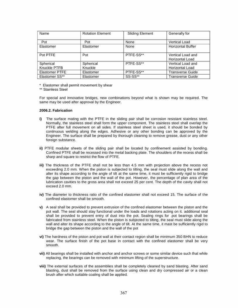
Name Rotation Element Sliding Element Generally for
Pot Pot None Vertical LoadElastomer Elastomer None Horizontal Buffer
Pot PTFE Pot PTFE-SS** Vertical Load andHorizontal Load
SphericalKnuckle PTFB
SphericalKnuckle
PTFE-SS** Vertical Load andHorizontal Load
Elastomer PTFE Elastomer PTFE-SS** Transverse GuideElastomer SS** Elastomer SS-SS** Transverse Guide
* Elastomer shall permit movement by shear** Stainless Steel
For special and innovative bridges, new combinations beyond what is shown may be required. Thesame may be used after approval by the Engineer.
2006.2. Fabrication
i) The surface mating with the PTFE in the sliding pair shall be corrosion resistant stainless steel.Normally, the stainless steel shall form the upper component. The stainless steel shall overlap thePTFE after full movement on all sides. If stainless steel sheet is used, it should be bonded bycontinuous welding along the edges. Adhesive or any other bonding can be approved by theEngineer. The surface shall be prepared by thorough cleaning to remove grease, dust or any otherforeign substance.
ii) PTFE modular sheets of the sliding pair shall be located by confinement assisted by bonding.Confined PTFE shall be recessed into the metal backing plate. The shoulders of the recess shall besharp and square to restrict the flow of PTFE.
iii) The thickness of the PTFE shall not be less than 4.5 mm with projection above the recess notexceeding 2.0 mm. When the piston is subjected to tilting, the seal must slide along the wall andalter its shape according to the angle of tilt at the same time, it must be sufficiently rigid to bridgethe gap between the piston and the wall of the pot. However, the percentage of plan area of thelubrication cavities to the gross area shall not exceed 25 per cent. The depth of the cavity shall notexceed 2.0 mm.
iv) The diameter to thickness ratio of the confined elastomer shall not exceed 15. The surface of theconfined elastomer shall be smooth.
v) A seal shall be provided to prevent extrusion of the confined elastomer between the piston and thepot wall. The seal should stay functional under the loads and rotations acting on it. additional sealshall be provided to prevent entry of dust into the pot. Sealing rings for .pot bearings shall befabricated from stainless steel. When the piston is subjected to tilting, the seal must slide along thewall and alter its shape according to the angle of tilt. At the same time, it mast be sufficiently rigid tobridge the gap between the piston and the wall of the pot
vi) The hardness of the piston and pot wall at their contact region shall be minimum 350 BHN to reducewear. The surface finish of the pot base in contact with the confined elastomer shall be verysmooth.
vii) All bearings shall be installed with anchor and anchor screws or some similar device such that whilereplacing, the bearings can be removed with minimum lifting of the superstructure.
viii) The external surfaces of the assemblies shall be completely cleaned by sand blasting. After sandblasting, dust shall be removed from the surface using clean and dry compressed air or a cleanbrush after which suitable coaling shall be applied.

ix) Pot bearings including all pans as shown on the drawings shall be fully shop assembled at themanufacturer’s works to ensure proper fitting of all pans.
2006.3. Materials
a) Steel
i) Structural steel shall conform to! S: 226 and IS; 2062, as applicable.
ii) Cast steel shall conform to Gr 280-520W of 15:1030. 0.3 to 0.5 per cent copper may be added loincrease the corrosion resistance properties.
iii) Stainless steel shall conform to A1SL3W or XO4Crl8NilO of IS:69ll for ordinary applications. Forapplications with adverse/corrosive environment, the stainless steel shall conform to A1SI:316L orO2Crl7NiI2Mo2 of IS:6911.
b) PTFEPTFE (poly tetra fluoro ethylene) shall be of unfilled pure virgin quality. It shall be free sintered. Themechanical properties of unfilled PTFE shall comply with Grade A of BS:37S4.
c) Elastomer
The confined elastomer inside pot will have the following properties:a) Hardness IRHD IS: 3400 (Part II) 50 + 5b) Min tensile MPa IS: 3400 (Pan I) 15.5 strengthc) Min elongation at break,) shall be as per Table 2000-1Max compression set and) "Properties of Elastomer"Accelerated ageing)
For other details, refer to Clause 2005.1.
2006.4. Workmanship
2006.4.1. Welding
All welding shall conform to IS: 9595 with electrodes of suitable grade as per IS: 814. Preheating andpost weld stress relieving shall be done as per IS: 9595.
2006.4.2. Cast steel assemblies: Cast steel for pot bearing assemblies shall conform lo requirementsof relevant IS. Castings shall be true lo the forms arid dimensions shown on the drawings, and shall befree from pouring faults, sponginess, cracks, blow holes and other defects affecting their appearance ortheir strength. Warped or distorted castings shall not be accepted. Exposed surfaces shall le smoothand dense.All irregularities, fins or risers shall be ground off flush with the adjacent surface. Castings with visiblecracks, blow holes, or similar blemishes shall be rejected if the imperfections are located on bearingsurfaces or cannot be remedied to the satisfaction of the Engineer. Imperfections which are not locatedon bearing surfaces shall be cleaned out filled with weld metal of the appropriate composition andground flush with adjacent surfaces.
2006.4.3. Structural steel assemblies: Defects arising from the fabrication of the steel shall beinspected by the Engineer, who will decide whether the materials may be repaired by the Contractor orwill be rejected. The cost of repairs or replacement shall be borne by the Contractor.All steel whether fabricated or not, shall be stored above the ground on platforms, skids, or othersupports, and adequately protected against corrosion. Excessively rusted, bent or damaged steel shallbe rejected.All plates shall be flat and rolled bars and shapes straight before marking our or being worked.Straightening shall be done by methods which shall not damage the material. Sharp kinks and bendsshall be the cause for rejection.Steel may be flame cut to shape and length so that a regular surface, free from excessive gouges andstriations is obtained. Flame cutting by hand shall be done only with the approval of the Engineer,Exposed corners shall be machined or ground.
2006.4.4. Tolerancesi) Plan dimensions : -0 10 +5 mm
ii) Overall height : -0 to +3 mmiii) Height of elastomer : ± 5 pet centiv) Height of any steel componenta) Machined : -0 to +1 mmb) Unmachined : Class 2 of IS: 4897v) Stainless steel sliding surfacea) Flatness : 0.0004L, where L = length in
Direction of measurementb) Surface Finish : Ra < 0.25 pm as per IS: 3073
2006.4.5. Painting
i) All non-working surfaces shall be coated with two coats of epoxy primer and one or more coat eachof epoxy intermediate and finish, total thickness < 0.150 Urn or any other painting scheme asapproved by the Engineer.
ii) Silicon grease shall be applied at me PTFE/SS interface after testing.iii) Anchor sleeves shall be cement coated at the manufacturer’s works.
2006.5. Test
2006.5.1. Raw materials: Necessary test certificates for all raw materials as in Clause 2006.3 aboveshall be furnished by manufacturers. Reference may also be made to Clause 2005.1 for tests onelastomers.
2006.5.2. Test on casting: Tests specified in IS: 1030 shall be performed. Castings shall beultrasonically tested and certificates submitted. Quality level of castings shall be level 3 as perIS: 9565.
2006.5.3. Test on welding: All welding shall be tested by Dye Penetration method. But welding shallbe tested by Ultrasonic method. Soundness of welding shall be certified by the manufacturer.
2006.5.4. Acceptance test on bearingi) All bearings shall be checked for overall dimensions.ii) All bearings shall be load tested to 1.1 times maximum design capacity including seismic force.Bearing tested at higher loads cannot be used.iii) A pair of bearings selected at random wilt undergo testing in order to determine the coefficient offriction "µ". The coefficient of friction shall be < 0.05 at the design load.iv) Two bearings selected at random shall be tested for permissible rotation.
2006.6. Installation of POT-cum-PTFE Bearings
2006.6.1. General
i) Care shall be taken during installation of the bearings to permit their correct functioning inaccordance with the design scheme.
ii) To prevent contamination, dismantling of the bearings at site shall not be done.
iii) The load shall be transferred onto the bearings only when the bedding material has developedsufficient strength. The props for the formwork shall only be removed after lapse of appropriatetime. In special cases, this can be ensured by suitable devices like jades, etc.
iv) Temporary clamps and shims (introduced 10 maintain working clearance) shall be removed at anappropriate time, before the bearing is required to permit movement,
v) Permitted installation tolerance of the bearing from plane of sliding shall be maintained.
vi) Cement based non- shrink grout with air releasing additive and epoxy based grout, whichever isspecified shall be first tried at the site. For the proprietary grout mixes, appropriate instructions fromthe manufacturer shall be followed specially with regard to the following:
a) Preparation->concrete cleaning, roughening, pre-soaking, etc.
b) Forms ->sturdiness, leak proofing, shape, header funnel vents, etc.c) Bearing Base->cleaning, etc.d) Placement->mixing, consistency, lime period, finishing, etc,e) Protection->curing, ambient temperature, etc.
2006.6.2. In-situ casting of superstructure
i) Formwork around the bearing shall be carefully scaled to prevent leakage
ii) Sliding plates shall be fully supported and care taken to prevent tilling, displacement or distortion ofthe bearings under the weight of wet concrete.
iii) Bearings shall be protected during concreting operation. Any mortar contaminating the bearing shallbe completely removed before it sets.
2006.6.3. Seating of bearing
A. Using Template
i) Template with required rigidity and matching holes corresponding to the base of the bearing shall beused.
ii) All the anchors shall be fitted to the lower face of the template using the anchor screws but withsteel washer replacing the elastomer washers, Separate screws may be used in case of inconvenience in the length of the original anchor screws.
iii) The template assembly shall be located with regard lo level and alignment. !t shall be ensured thatthe lop of the anchors lie in a horizontal plane al (he required elevation. The anchors shall betied/welded lo reinforcements to avoid displacement during concreting.
iv) Concreting of the pedestal/pier cap shall be done to a level leaving a gap of’25-50 mm below thetemplate.
v) The template and steel washers shall be removed prior to placement of the bearing assembly withtemporary clamps. The hearing assembly shall be fitted lo the anchors with the help of anchorscrews and elastomer washers, Level al the bearing shall be checked.
vi) The gap below the bearing assembly shall be grouted with cement based grout. Reference may bemade to Clause 2006.6.1 (vi).
B. Without Template with Gap
i) Pockets commensurate with the sizes of the anchors shall be kept in pedestals during concreting ofthe same. The pedestal shall be cast approximately 25 mm short of the required finished level.
ii) Anchors shall be fitted lo the bearing bottom with elastomer washers and anchor screws. Thebearing assembly shall be sealed in the location on sled chairs/packs. The anchors filled below thebearing shall go into pockets in the bed block. Level and alignment of the bearing shall be checked.Ii shall be ensured that the bearing sits in a horizontal plane.
iii) The gap below the bearing assembly including anchor pockets shall be grouted with cement basedgrout. Reference may be made to Clause 2006,6,1
C. Without Template without Gap
Elongated pockets commensurate with the sizes of the anchors shall be kept in pedestals duringconcreting of the same. The geometry and location of the anchor pockets (with tapered funnelextension, if required) shall be such that after placement of the bearing the pockets can be successfullygrouted. The pedestal shall be cast 5 mm - 15 mm short of the required finished level. The requiredlevel shall be achieved by chipping before placement of the bearing. Careful control shall be exercisedto cast at the exact finished level or 1mm - 3 mm down from the required Finished level.
D. Seating of bearings shall be as per manufacturer's instructions.
2007. INSPECTION AND TESTING
Where any patents are used, the manufacturer’s certificate with test proofs shall be submitted alongwith the design and got approved by the Engineer before their use in work.
2008. TESTS AND STANDARDS OF ACCEPTANCE
The materials shall be tested in accordance with these specifications and shall meet the prescribedcriteria. The work shall conform to these specifications and shall meet theprescribed standards of acceptance.
2009. MEASUREMENTS FOR PAYMENT
Bearings shall be measured in numbers, according to their capacities and particular specifications givenon the drawings. The quantity of elastomeric bearings shall be measured in cubic centimeters offinished dimensions.
2010. RATE
The contract unit rate of each type of bearing shall include the cost of supplying and fixing the bearingsin position complete as specified on the drawings or as decided by the Engineer. The rate shall alsoinclude the cost of samples and their testing when desired by the Engineer.In case of steel bearings the rate shall include the cost of all nuts, bolts, the cost of all tests prescribedin the specifications and shown on the drawings.Where the Department supplies the bearings, the rate for fixing them shall include the cost of anchorbolts, their fixing, transport of bearings from the place of supply to the site, handling and placing them inposition as per direction of the Engineer.

2100 Open Foundations

CONTENT
Clause No Description2101 DESCRIPTION
2102 MATERIALS
2103 GENERAL
2104 WORKMANSHIP
2105 TESTS AND STANDARDS OF ACCEPTANCE
2106 TOLERANCES
2107 MEASUREMENT FOR PAYMENT
2108 RATE
2101. DESCRIPTIONThe work shall cover furnishing and providing plain or reinforced concrete foundation placed in
open excavation, in accordance with the drawings and these specifications or as directed by theEngineer.
2102. MATERIALSMaterials shall conform to Section 1000 of these Specifications.
2103. GENERALA method statement for construction indicating the following shall be submitted by the
Contractor for approval of the Engineer, well in advance of the commencement of open foundation:i) Sources of Materialsii) Design, erection and removal of formworkiii) Production, transportation, laying and curing of concreteiv) Personnel employed for execution and supervisionv) Tests and sampling proceduresvi) Equipment detailsvii) Any other point
Necessary arrangements for execution under water wherever necessary, shall be included inmethod statement. Dimensions, lines and levels shall be set out and checked with respect topermanent reference lines and permanent bench mark.
2104. WORKMANSHIP2104.1. Preparation of Foundations
Excavation for laying the foundation shall be carried out in accordance with Section 300 ofthese specifications. The last 300 mm of excavation shall be done just before laying of lean concretebelow foundation.
In the event of excavation having been made deeper than that shown on the drawing or asordered by the Engineer, the extra depth shall be made up with M15 concrete in case of foundationresting on soil and foundation grade concrete for foundations in rock, at the cost of the Contractor andshall be considered as incidental work. Special care shall be taken not to disturb the bearing surface.Open foundations shall be constructed in dry conditions and the Contractor shall provide for adequatedewatering arrangements to the satisfaction of the Engineer.
2104.2. Setting OutThe plan dimensions of the foundation shall be set out at the bottom of foundation trench and
checked with respect to original reference line and axis. It shall be ensured that at no point the bearingsurface is higher than the founding level shown on the drawing or as directed by the Engineer.
2104.3. ConstructionWhere the bearing surface is earth, a layer of M15 concrete shall be provided below foundation
concrete. The thickness of lean concrete layer shall be 100 mm minimum unless otherwise specified.No formwork is necessary for the lean concrete layer. For foundation concrete work, side formworkshall be used. Formwork for top of the foundation concrete shall also be provided, if its top has slopessteeper than 1 (vertical) to 3 (horizontal). When concrete is laid in slope without top formwork, theslump of the concrete shall be carefully maintained to ensure that compaction is possible withoutslippage down the slope of freshly placed concrete. In certain cases it may be necessary to build thetop formwork progressively as the concreting proceedsup the slope. Reinforcement shall be laid as shown on the drawing. Before laying of lean concretelayer, the earth surface shall be cleaned of all loose material and wetted. Care shall be taken to avoidmuddy surface. If any portion of the surface has been spoiled by over-wetting, the same shall beremoved. Concrete M15 shall be laid to the thickness as required. No construction joint shall beprovided in the lean concrete.
Before laying foundation concrete, the lean concrete or hard rock surface shall be cleaned of allloose material and lightly moistened. Foundation concrete of required dimensions and shape shall belaid continuously upto the location of construction joint shown on the drawing or as directed by theEngineer.
Formwork and concrete shall conform to Sections 1500 and 1700 respectively of thesespecifications. Furnishing and providing steel reinforcement shall conform to Section 1600.
The concrete surface shall be finished smooth with a trowel. The location of construction jointand its treatment shall be done as per requirements of Section 1700. Formwork shall be removed notearlier than 24 hours after placing of concrete. Where formwork has been provided for top surface, thesame shall be removed as soon as concrete has hardened. Curing of concrete shall be carried out bywetting of formwork before removal. After its removal, curing shall be done by laying not less than 10cm of loose moistened sand, free from clod or gravel and shall be kept continuously moist for a periodof 7 days.
Dewatering, where necessary for laying of concrete, shall be carried out adopting any one ofthe following procedures or any other method approved by the Engineer;i) A pit or trench deeper than the foundation level as necessary may be dug beyond the
foundation pit during construction so that the water level is kept below the foundation level.ii) Water table is depressed by well point system or other methods.iii) Use of steel/concrete caissons or sheet piling for creating in enclosure for the foundations,
which can subsequently be dewatered.
Before backfilling is commenced, loose sand laid on foundation shall be removed anddispersed as directed by the Engineer. All spaces excavated and not occupied by the foundation orother permanent works shall be refilled with earth upto surface of surrounding ground in accordancewith Section 300. In case of excavation in rock, the annular space around foundation shall be filled withM15 concrete upto the top of rock.
The protective works, where provided shall be completed before the floods so that thefoundation does net get undermined.
2105. TESTS AND STANDARDS OF ACCEPTANCEThe materials shall be tested in accordance with these Specifications and shall meet the
prescribed criteria.
The work shall conform to these Specifications and shall meet the prescribed standards ofacceptance. No point of the surface of the lean concrete in the case of foundation on soil or the surfaceof hard rock in the case of foundation of hard rock, shall be higher man the founding level shown en thedrawing or as ordered by the Engineer. Levels of the surface shall be taken at intervals of not morethan 3 metres centre to centre, subject to a minimum of nine levels on the surface.
2106. TOLERANCESa) Variation in dimensions : +50 min - 10 mmb) Misplacement from specified position in plan : 15 mmc) Surface irregularities measured with 3 m straight edge : 5 mmd) Variation of levels at the top : +25 mm
2107. MEASUREMENT FOR PAYMENTExcavation in foundation shall be measured in accordance with Section 300 based on the
quantity ordered or as shown on the drawing. Lean concrete shall be measured in cubic metres inaccordance with Section 1700, based on the quantity ordered or as shown on the drawing.
Concrete in foundation shall be measured in cubic metres in accordance with Section 1700,based on the quantity ordered or as shown on the drawing.
Reinforcement steel shall be measured in tonnes in accordance with Section 1600, based onthe quantity ordered or as shown on the drawing.
2108. RATEThe contract unit rates for excavation in foundation, lean concrete and concrete in foundation
and reinforcement steel shall include all works as given in respective sections of these specificationsand cover all incidental items for furnishing and providing open foundation as mentioned in this Section.

2200 Sub-structure

CONTENT
Clause No Description2201 DESCRIPTION
2202 MATERIALS
2203 GENERAL
2204 PIERS AND ABUTMENTS
2205 PIER CAP AND ABUTMENT CAP
2206 DIRT/ BALLAST WALL, RETURN WALL AND WING WALL
2207 TESTS AND STANDARDS OF ACCEPTANCE
2208 TOLERANCES IN CONCRETE ELEMENTS
2209 MEASUREMENTS FOR PAYMENT
2210 RATE

2201. DESCRIPTIONThe work shall cover furnishing and providing of masonry or reinforced concrete sub-structure
in accordance with the drawings and as per these specifications or as directed by the Engineer.
2202. MATERIALSMaterials shall conform to Section 1000 of these Specifications.
2203. GENERALA method statement for construction indicating the following shall be submitted by the
Contractor for approval of the Engineer, well in advance of the commencement of sub-structure :
i) Sources of Materialsii) Design, erection and removal of formworkiii) Production, transportation, laying and curing of concreteiv) Personnel employed for execution and supervisionv) Tests and sampling proceduresvi) Equipment detailsvii) Any other point
Arrangements for execution under water wherever necessary, shall be included in methodstatement. Dimensions, lines and levels shall be set out and checked with respect to permanentreference lines and permanent bench mark.
2204. PIERS AND ABUTMENTSMasonry, formwork, concrete and reinforcement for piers and abutments shall conform to
relevant sections of these specifications. In case of concrete piers, the number of horizontalconstruction joints shall be kept minimum. Construction joints shall be avoided in splash zones unlessspecifically permitted by the Engineer and provided they are treated in accordance with specialprovisions. No vertical construction joint shall be provided. The work shall conform strictly to thedrawings or as directed by the Engineer.
In case of tall piers and abutments, use of slipform shall be preferred. The design, erection andraising of slipform shall be subject to special specifications which will be furnished by the Contractor.The concrete shall also be subject to additional specifications as necessary. All specifications andarrangements shall be subject lo the approval of the Engineer.
The surface of foundation/well cap/pile cap shall be scrapped with wire brush and all loosematerials removed. In case reinforcing bars projecting from foundations are coated with cement slurry,the same shall "be removed by tapping, hammering or wire brushing. Care shall be taken to remove allloose materials around reinforcements. Just before commencing masonry or concrete work, the surfaceshall be thoroughly welled.
In case of solid (non-spill through type) abutments, weep holes as shown on the drawings or asdirected by the Engineer, shall be provided in conformity with Section 2706.
The surface finish shall be smooth, except the earth face of abutments which shall be roughfinished. In case of abutments likely to experience considerable movement on account of backfill ofapproaches and settlement of foundations, the construction of the abutment shall be followed by fillingup of embankment in layers to, the full height to allow for the anticipated movement during constructionperiod before casting of superstructure.
2205. PIER CAP AND ABUTMENT CAPFormwork, reinforcement and concrete shall conform to relevant sections of these
specifications. The locations and levels of pier cap/abutment cap/pedestals and bolts for fixing bearingsshall be checked carefully to ensure alignment in accordance with the drawings of the bridge. Thesurface of cap shall be finished smooth and shall have a slope for draining of water as shown on thedrawings or as directed by the Engineer. For short span slab bridges with continuous support on piercaps, the surface shall be cast horizontal. The lop surface of the pedestal on which bearings are to beplaced shall also k- cast horizontal.
The surface on which elastomeric bearings are to be placed shall be wood float finished to alevel plane which shall not vary more than 1.5 mm from straight edge placed in any direction across thearea. The surface on which other bearings (steel bearings, pot bearings) are to be placed shall be castabout 25 mm below the bottom level of bearings and as indicated on the drawings.
2206. DIRT/ BALLAST WALL, RETURN WALL AND WING WALLMasonry, concrete and reinforcement shall conform to relevant sections of these specifications.
In case of cantilever return walls, no construction joint shall generally be permitted. Wherever feasible,the concreting in cantilever return walls shall be carried out in continuation of the ballast wall.
For gravity type masonry and concrete return and wing wall, the surface of foundation shall beprepared in the same manner as prescribed for construction of abutment. No horizontal constructionjoint shall be provided. If shown on drawing or directed by the Engineer, vertical construction joint maybe provided. Vertical expansion gap of 20 mm shall be provided in return wall/wing wall at every 10metre intervals or as directed by the Engineer. Weep holes shall be provided as prescribed forabutments or as shown on the drawings.
Formwork, reinforcement and concrete in dirt/ballast wall shall conform to relevant sections ofthese specifications. The finish of the surface on the earth side shall be rough while the front face shallbe smooth finished.
Architectural coping for wing wall/return wall in brick masonry shall conform to section 1300.
2207. TESTS AND STANDARDS OF ACCEPTANCEThe materials shall be tested in accordance with these specifications and shall meet the
prescribed criteria. The work shall conform to these specifications and shall meet the prescribedstandards of acceptance.
2208. TOLERANCES IN CONCRETE ELEMENTS(a) Variation in cross- sectional dimensions : +10 mm, -5mm(b) Misplacement from specified position in plan : 10 mm(c) Variation of levels at the top : ±10 mm(d) Variations of reduced levels of bearing areas : ± 5 mm(e) Variations from plumb over full height : ±10 mm(f) Surface irregularities measured with 3 m straight edge
All surfaces except bearing areas : 5 mmBearing areas : 3 mm
2209. MEASUREMENTS FOR PAYMENTMasonry in sub-structure shall be measured in cubic metres in accordance with Section 1300
or 1400, based on the quantities ordered or as shown on the drawing. Concrete in sub-structure shallbe measured in cubic metres in accordance with Section 1700, based on the quantity ordered or asshown on the drawing. No deduction shall be made for weep holes.
Steel in concrete of sub-structures shall be measured in tonnes, in accordance with Section1600, based on the quantity ordered or as shown on the drawing.
Weep holes shall be measured as per Section 2700, based on the quantity ordered or asshown on the drawings.
2210. RATEThe contract unit rates for masonry, concrete, reinforcement and weep holes shall include all
works as given in respective sections of these specifications and cover all incidental items forfurnishing and providing substructure as mentioned in this Section.

2300 Concrete Superstructure

CONTENT
Clause No Description2301 DESCRIPTION
2302 MATERIALS
2303 GENERAL
2304 REINFORCED CONCRETE CONSTRUCTION
2305 PRESTRESSED CONCRETE CONSTRUCTION
2306 TOLERANCES
2307 TESTS AND STANDARDS OF ACCEPTANCE
2308 MEASUREMENTS FOR PAYMENT
2309 RATE
2301. DESCRIPTIONThe work shall cover furnishing and providing of concrete superstructure in accordance with the
drawings as per these specifications or as directed by the Engineer.
2302. MATERIALSMaterials shall conform to Section 1000 of these Specifications.
2303. GENERAL2303.1. A method statement for construction, indicating the following, shall be submitted by theContractor for approval of the Engineer, well in advance of the commencement of the construction ofsuperstructure :i) Sources of Materialsii) Design, erection and removal of formworkiii) Production, transportation, laying and curing of concreteiv) Prestressing system, if applicablev) Personnel employed for execution and supervisionvi) Tests and samp ling procedurevii) Equipment detailsviii) Any other point
2303.2. Dimensions, lines and levels shall be set out and checked with respect to permanent referencetines and permanent bench mark so that the final product is in accordance with the drawings or asdirected by the Engineer.
2303.3. The work shall conform to the following sections besides stipulations in this section with regardto specific type of construction:i) Formwork Section 1500ii) Steel Reinforcement Section 1600iii) Structural Concrete Section 1700iv) Presiressing Section 1800
Additionally, some of the common types of superstructure construction shall have features asdiscussed in this Section.
2304. REINFORCED CONCRETE CONSTRUCTION2304.1. Solid Slabs
Where adjacent span of slab has already been cast, the expansion joint and filler board shall beplaced abutting the already cast span which shall form the shutter on that side of the new span to becast. The whole of the slab shall be cast with reinforcement embedded for the road kerb and railings.No other construction joint shall be allowed except with the express permission of the Engineer.
Where wearing coat is required to be provided, after the deck slab has been cast, the surfaceof the slab shall be finished rough, but true to lines and levels as shown on the drawings, before theconcrete has hardened. The areas of construction joints shall be treated in the prescribed manner.
The lop of the slab shall be covered with clean moist sand as soon as the top surface hashardened. Curing shall be carried out as per Section 1700.
Where the slab is resting on bearings, the same shall be placed in position in accordance withthe drawings, before casting of deck slab,
2304.2. RCC T-Beam and SlabProvision of construction joint shall conform to .the drawings or as per directions of the
Engineer. No construction joint shall be provided between the bottom bulb and the web. If not indicatedon the drawing, construction joint may be provided at the junction of the web and the fillet between theweb and the deck slab with the permission of the Engineer.
The portions of deck slab near expansion joints shall be cast along with reinforcements andembedments for expansion joints. For this purpose, the portion of deck slab near expansion joints maybe cast in a subsequent stage, if permitted by the Engineer.
The surface finish of the deck slab shall be finished rough but true to lines and levels as shownoh the drawings before the concrete has hardened. Care shall be taken for setting of bearings asindicated on the drawings.
2305. PRESTRESSED CONCRETE CONSTRUCTION2305.1. PSC Girder and Composite RCC Slab
PSC Girder may be precast or cast- in-situ as mentioned on the drawing or as directed by theEngineer. Girders may be post-tensioned or pre-tensioned. Where precast construction is required tobe adopted, selection of casting yard and details of methodology and of equipment for shifting andlaunching of girders shall be included in the method statement.
In case of cast- in-situ construction, the sequence of construction including side shifting ofgirders, if applicable, and placing on bearings shall be in accordance with the drawings.
The PSC girder constituting the top flange, web and the bottom flange shall be concreted in asingle operation without any construction joint.
The portions of deck slab near expansion joints shall be cast along - with reinforcements andembedments for expansion joints. For this purpose, the portion of deck slab near expansion joints maybe cast in a subsequent stage, if permitted by the Engineer.
The surface finish of the deck slab shall be finished rough but true to lines and levels as shownon the drawings before die concrete has hardened. Care shall be taken for setting of bearings asindicated on the drawings.
2305.2. Box GirderBox girders may be simply supported or continuous. Simply supported box girders shall have
minimum construction joints as approved by the Engineer. In the case of continuous box girders thesequence of construction and location of construction joints shall strictly follow the drawings.
The box section shall be constructed with a maximum of one construction joint located in theweb below the fillet between the deck slab and web. If permitted by the Engineer, one additionalconstruction joint may be permitted and this construction joint shall be located in the web above the filletbetween the soffit slab and web.
The portions of deck slab near expansion joints shall be cast alongwith reinforcements andembedments for expansion joints. For this purpose, the portion of deck slab near expansion joints maybe cast in a subsequent stage, if permitted by the Engineer.
The surface finish of the deck slab shall be finished rough but true to lines and levels as shownon the drawings before the concrete has hardened. Care shall be taken for setting of bearings asindicated on the drawings.
23053. Cantilever ConstructionContinuity of untensioned reinforcement from one segment to the next must be ensured by
providing full lap length as necessary.
The design of the superstructure shall take into account the following aspects which form anintegral part of the construction operations :a) Stability against over-turning for each statical condition through which the assembly passes,
shall be checked.b) Stresses at each preceding segment joint with the addition of every segment or change of
statical conditions shall be checked. The load of equipment as well as construction live loadshall be taken into account.
c) Precambering of the superstructure during construction shall be done in such a manner that thefinally constructed structure under permanent load strains the final profile intended in thedrawings.
2306. TOLERANCES2306.1. Precast Concrete Superstructure
Variation in cross-sectional dimensions:
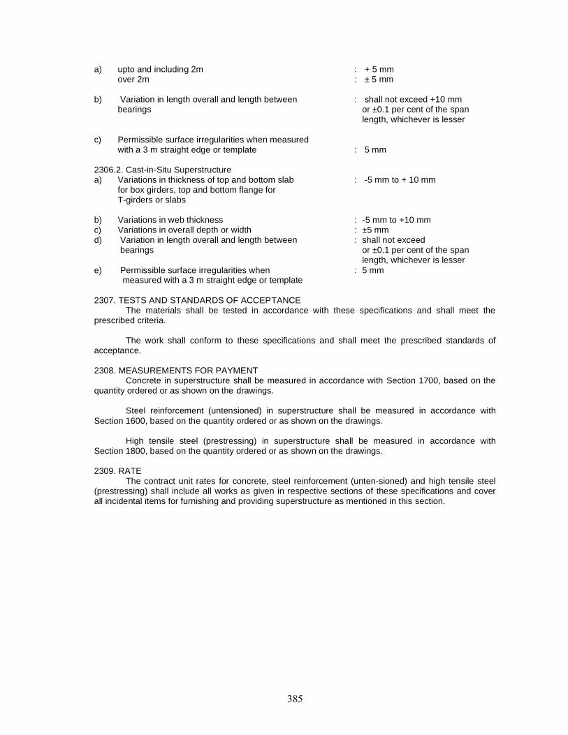
a) upto and including 2m : + 5 mmover 2m : ± 5 mm
b) Variation in length overall and length between : shall not exceed +10 mmbearings or ±0.1 per cent of the span
length, whichever is lesser
c) Permissible surface irregularities when measuredwith a 3 m straight edge or template : 5 mm
2306.2. Cast-in-Situ Superstructurea) Variations in thickness of top and bottom slab : -5 mm to + 10 mm
for box girders, top and bottom flange forT-girders or slabs
b) Variations in web thickness : -5 mm to +10 mmc) Variations in overall depth or width : ±5 mmd) Variation in length overall and length between : shall not exceed
bearings or ±0.1 per cent of the spanlength, whichever is lesser
e) Permissible surface irregularities when : 5 mmmeasured with a 3 m straight edge or template
2307. TESTS AND STANDARDS OF ACCEPTANCEThe materials shall be tested in accordance with these specifications and shall meet the
prescribed criteria.
The work shall conform to these specifications and shall meet the prescribed standards ofacceptance.
2308. MEASUREMENTS FOR PAYMENTConcrete in superstructure shall be measured in accordance with Section 1700, based on the
quantity ordered or as shown on the drawings.
Steel reinforcement (untensioned) in superstructure shall be measured in accordance withSection 1600, based on the quantity ordered or as shown on the drawings.
High tensile steel (prestressing) in superstructure shall be measured in accordance withSection 1800, based on the quantity ordered or as shown on the drawings.
2309. RATEThe contract unit rates for concrete, steel reinforcement (unten-sioned) and high tensile steel
(prestressing) shall include all works as given in respective sections of these specifications and coverall incidental items for furnishing and providing superstructure as mentioned in this section.

2400 Surface and Sub-surface GeotechnicalExploration
CONTENT
Clause No Description2401 GENERAL
2402 PRELIMINARY INVESTIGATION
2403 DETAILED EXPLORATION
2404 EXPLORATION FOR BRIDGE FOUNDATIONS RESTING ON ROCK
2405 BORING
2406 RECORDS OF BORINGS AND TRIAL PITS
2407 METHODS OF SAMPLING
2408 PROCEDURE FOR TAKING SAMPLES
2409 PROTECTION, HANDLING AND LABELLING OF SAMPLES
2410 TESTS FOR EXPLORATION OF SHALLOW FOUNDATIONS OF
BRIDGES
2411 TESTS FOR EXPLORATION FOR DEEP FOUNDATIONS OF BRIDGES
2412 TESTING OF MATERIAL FOR GUIDE BUND AND HIGH
EMBANKMENT AND ITS FOUNDATIONS
2413 MEASUREMENTS FOR PAYMENT
2414 RATE
2401. GENERAL2401.1. The objective of sub-surface exploration is to determine the suitability or otherwise of the soil orrock surrounding the foundation and soil parameters and rock characteristics for the design offoundation by in-situ testing or testing of samples/cores taken out of exploration. The sub-surfaceexploration shall be planned in such a way that different types of soil upto the desired depth and theirprofile for the full proposed length of the bridge can be recorded and other information such asmechanical and physical properties like grain-size distribution, sensitivity, any existence of deleteriousmaterial in soil or ground water, etc., are determined alongwith soil parameters and rock characteristics.The sub-surface exploration shall also throw light on porosity of rock and subsidence due to mining,ground water level, artesian condition, if any, likely sinking and driving effort, likely constructionaldifficulties, etc.
2401.2. Field InvestigationField investigations of sub-surface has. usually three phases :i) Reconnaissanceii) Preliminary Explorationsiii) Detailed Explorations
2401.2.1. Reconnaissance includes a review of available topo graphic and geological information, aerialphotographs and data from previous investigations and site examination".
2401.2.2. Preliminary investigation shall include the study of existing geological information, previoussite reports, geological maps, air photos, etc. and surface geological examination. For large andimportant structures the information may be supplemented by geophysical methods. In some caseswhere no previous sub-strata data are available, exploratory geophysical investigation may need to besupplemented by resorting to a few bore-holes. These will help to narrow down the number of sitesunder consideration and also to locate the most desirable location for detailed sub-surface investigationlike bore or drill holes, sounding probes, etc.
2401.2.3. The scope of detailed investigation for bridges may be decided based on data obtained afterpreliminary investigation. Based on data obtained after preliminary investigations, the bridge site, typeof structure with span arrangement and the location and type of foundations, shall be tentativelydecided. Thereafter, the scope of detailed investigation including the extent of exploration, number ofbore-holes, type of soundings, type of tests, number of tests, etc., shall be decided, so that adequatedata considered to be necessary for the detailed design and execution, are obtained.
2401.2.4 The width of exploration: One purpose of detailed exploration for high embankments is toascertain the average shear strength of each strata. The other purpose is to ascertain thecompressibility of the clayey strata. It is, therefore, necessary that detailed and well illustrateddescription of the characteristics of stratification should be prepared, After the general shape and trendof the boundaries of the various soil deposits have been determined and rough assessment of theirstrength has been made by sub-surface sounding, with or without sampling in exploratory boring, thelocation of bore-hole(s) for undisturbed sampling shall be decided. At least one representativeundisturbed sample should be collected from each strata. When the homogeneous strata is very thick,one representativesample shall be collected for each 3 m thickness of the strata.
2401.3. Soil investigation for foundations shall contain a programme for boring and retrieval of samples.The field work shall consist of excavation, drilling of bore-holes for the purposes of collection ofundisturbed and disturbed samples, standard penetration tests, in-situ vanetests, static and dynamiccone penetration tests, other field tests, as specified by the Engineer and preparation of bore- logs.Collection and preservation for testing of disturbed and undisturbed samples from bore holes, borrowpits, etc., as specified by the Engineer shall form a part of the above. All in-situ tests shall besupplemented by laboratory investigations. Relevant Indian Standards such as 15:1498, IS:1888,IS:1892, IS:2131, IS:2132, 15:2720, 15:4434 and 15:4968 and Appendix I of IRC:78, etc., shall befollowed for guidance.
2401.4. The soundings by dynamic method shall be carried out in bore-holes using a standard sampleras specified in 15:2131.
2402. PRELIMINARY INVESTIGATION2402.1. Foundations
2402.1.1. Preliminary exploration shall be carried out to determine the soil profile showing theboundaries between the different soil types and between loose and dense parts in the same type ofdeposit. For guidance reference may be made to IRC:75. For this purpose, as a first step, a suitabletype of sub-surface sounding (e.g. static or dynamic cone penetration test) shall be carried out. Asmany soundings as necessary should be made, until the penetration data is complete enough to leaveno doubt concerning the general shape an d the trend of boundaries of the various soil deposits.Exploratory drill holes should then be made at one or two locations where average condition prevailsand near those few points where the penetration diagrams indicate maximum deviations from theaverage.
2402.1.2. The exploration shall cover the entire length of the bridge and also extend at either side for adistance about twice the depth below bed of the last main foundations. If there is any necessity fordesigning investigation for approaches particularly on soft soil or with high embankment or there is apossibility of considering alternatives between viaduct or earthen embankment, the extended lengthand location of the borings beyond the proposed location of abutment should be determined andexecuted.
2402.1.3. The depth of exploration should be at least 1½ times the minimum width of foundation belowthe proposed foundation level. Where such investigation end in any unsuitable or questionablefoundation material the exploration shall be extended to a sufficient depth into firm and stable soils orrock but not less than four times the minimum depth of foundation below the earlier contemplatedfoundation level. In case of good sound rock the stipulation of minimum depth may be decreasedbased on difficulty to conduct core drilling and the minimum depth may be restricted to 3 metres.
2402.2. Guidebund and EmbankmentThe depth of exploration should include all strata likely to affect stability of the embankment,
guide bund and/or cause undesirable settlement In general, the requirement of settlement governs thedepth of exploration for high embankments in particular. However, borings can be terminated atshallower depths when firm strata or bed rock is encountered. Ordinarily, the boring shall be taken to adepth of at least 1.5 times the height of embankment and guidebund. However, where highlycompressible strata are encountered, the boring may have to be taken deeper. In order to ensure thatfirm strata is sufficiently thick, the boring should extend 3 metre into the firm strata.
2403. DETAILED EXPLORATION2403.1. The exploration shall cover the entire length of the bridge and also extend at either end for adistance of about twice the depth below bed of the last main foundation to assess the effect of theapproach embankment on the end foundations. Generally the sub-surface investigations (preliminaryand detailed) for bridges shall extend to a depth below the anticipated foundation level equal to aboutone and a half times the width of the foundation. However, where such investigations end in anyunsuitable or questionable foundation material, the exploration shall be extended to a sufficient depthinto firm and stable soils or to rock.
2403.2. The type and extent of exploration shall be divided into the following groups as per requirementof foundation design and likely method of data collection:
i) Foundation requiring shallow depth of explorationii) Foundation requiring large depth of explorationiii) Fills behind abutments and protection works
2403.3. Location BoringWhere the data made available by detailed exploration indicates appreciable variation or where
variations in a particular foundation are likely to appreciably affect the construction (specially in case ofbridge foundations resting on rock), it will be necessary to resort to additional bores/soundings toestablish complete profile of the underlying strata. The additional borings /soundings shal l be decideddepending upon the extent of variation at a particular foundation location and should cover the entirearea of the particular foundation.
2403.4. Construction Stage ExplorationWhenever a change in the sub-soil strata/rock profile is encountered during construction,
explorations shall be resorted to establish the correct data for further decisions.
2403.5. Logging of bore-holes by radio-active methods shall be done for detailed investigations asspecified in the contract or in special provisions.
2403.6. For bridge works, the investigations shall be comprehensive enough to enable the designer toestimate or determine the following:
i) the engineering properties of the soil/rock,ii) the location and client of soft layers and gas pockets, if any, under the hard founding strata,iii) the geological condition like type of rock, faults, fissures or subsidence due to mining,
porosity etc,iv) the ground water level,v) artesian conditions, if any,vi) quality of water in contact with-the foundation,vii) the depth and extent of scour,viii) suitable depth of foundation,ix) the bearing opacity of the foundation,x) probable settlement and probable differential settlement of the foundation!,xi) likely linking or driving effort, andxii) likely conjunction difficulties.
2404. EXPLORATION FOR BRIDGE FOUNDATIONS RESTING ON ROCK2404.1. Investigation and interpretation of data for rock is a specialised work. To arrive at thecharacteristic strength of rock mass, reliance shall be placed more on in-situ tests in comparison tolaboratory tests. An engineering geologist shall also be associated in the exploration programme.
2404.2. Identification and classification of rock types for engineering purposes may in general be limitedto broad, basic geological classes in accordance with accepted practice. Strength of parent rock aloneis of limited value because overall characteristics depend considerably on character, spacing anddistribution of discontinuities of the rock mass, such as the joints, bedding planes, faults and weatheredseams. An important factor affecting the behaviour is the weathered zone at top.
2404.3. Basic Information Required from Explorationsi) Depth of rock strata and its variation over the site,ii) Whether isolated boulder or massive rock formation,iii) Extent and character of weathered zone,iv) Structure of rock - including bedding planes, faults, fissures, solution cavities etc.,v) Properties of rock material -strength, geological formation, etc.,vi) Erodibility of nock to the extent possible,vii) Colour of water.
2404.4. Exploration ProgrammeIf preliminary investigations have revealed presence of rock within levels where the foundation
is to rest, it is essential to take up detailed investigation to collect necessary information mentioned inclause 2404.3. The exploratory bore-hole shall be drilled into the rock to a depth of about 3 metres todistinguish a boulder from a continuous rock formation.
2404.5. The extent of exploration shall be adequate enough to give a complete picture of the rockprofile both in depth and across the channel width to assess the constructional difficulties in reachingthe foundation levels.
2404.6. The depth of boring in rock depends primarily on local geology, credibility of the rock, extent ofstructural loads to be transferred to foundation etc. Normally, it shall pass through the upper weatheredor otherwise weak zone, well into the sound rock. Minimum depth of boring in sound rock shall be 3metres.
2404.7. Detailed Investigation for Rock2404.7.1. This covers sounding, boring and drilling. An adequate investigation programme shall beplanned to cover the whole area for general characteristics and in particular the foundation location, toobtain definite information regarding rock-depth and its variation over the foundation area. The detailedprogramme of exploration will depend on the type and depth of over-burden, the size and importance ofthe structure, .etc. To decide this, geophysical methods adopted at the preliminary investigation stagewill be helpful, this data being supplemented by sounding, bore-holes and drill holes.
2404.7.2. Drilling through rock is a very specialised work and every care shall be taken to notice andrecord any small change during drilling. The time required to drill through a certain depth, amount ofcore recovery, physical condition, length of pieces of core, joints, colour of water residue, weatheringand evidence of disturbance and other effects shall be carefully noticed and entered in the drilling log.For guidance, 15:5313 may be referred to. The data shall be presented in accordance with IS;4464.
2404.7.3. The cores shall be stored properly in accordance with IS:4078.
2404.7.4. The rock cores obtained shall be subjected to following laboratory tests :i) Visual identification for texture, structure, composition, colour and grain size.ii) Laboratory tests shall be done for specific gravity, porosity and moisture content 2404.7.5. In-situtests shall be made in accordance with IS:7292; IS:7317; and IS:7746. In addition, laboratory tests canalso be made on samples.
2404.7.6. Use of in-situ tests for measuring strength and deformation characteristics shall be made.Use of bore-hole photography will be desirable to evaluate the presence of faults, fissures or cavities,etc.
2404.8. Special Cases2404.8.1. Investigation for conglomerate: A drill hole shall be made same as for rock. The samplescollected shall be subjected to suitable tests depending upon the material, special care shall be taken toascertain credibility of the matrix. Where possible, specially for shallow foundation, Plate Load Testshall be conducted.
2404.8.2. Investigation for laterites : The investigation shall be generally similar to that required forcohesive soils, use of penetration tests shall be preferred, if suitable correlation charts are available.This may be static or dynamic penetration tests or vane shear tests. In the case of hard laterite,recourse may have to be made to core drilling as for soft rocks. For laterites at shallow depths, use ofPlate Load Test may be advantageous.
2404.9. Caution2404.9.1. The interpretation of laboratory results on rock samples depends upon the relationship of thespecimens tested to the overall rock characteristics, enumerated in Appendix 1 of 1RC:78. For thispurpose, care shall be exercised in the choice of specimen size and its orientation in relation to the jointpattern.
2404.9.2. In some cases, the foundation behaviour will be dominated by a possible mode of failureinvolving movement along some joint surface, fissures or weak layer within a generally strong rocksystem and also by possible weathering. In-situ shear tests may be conducted wherever feasible, assuch tests are likely to give more representative data than the shear tests conducted on core samples.
2404.10. Presentation of DataThe data shall be given in diagrammatic form in 3 sheets giving the following details :Sheet 1 : Plan showing the position of bore-holes clearly marked so as to fix the position at a
future date.Sheet 2 : This shall contain the bore- log chart and test results of the samples separately for
each bore-hole/pit etc.Sheet 3 : This shall contain pictorial representation of the bore- log data to get an overall
picture of the soil profile at the cross- section of the river.
NOTE : For guidance, refer to 1RO.78.
2405. BORINGBoring shall be done by any of the following methods depending on the soil type and types of
samples required for the investigation:i) Auger Boringii) Shell and Auger Boringiii) Percussion Boringiv) Wash Boringv) Rotary Boring
For preliminary and detailed sub-surface investigation only rotary drills shall be used. Thecasing shall also be invariably provided with diameters not less than 150 mm upto the level of rock, ifany. However, use of percussion or wash boring equipment shall be permitted only to penetrate throughbouldery or gravelly strata for progressing the boring but not for the collection of samples. Whileconducting detailed borings, the resistance to the speed of drilling i.e. rate of penetration, core loss,etc., as already specified in Appendix 3 oflRC:78 shall be carefully recorded to evaluate the differenttypes of strata and to distinguish specially sand from sandstone, clay from shale, etc.
2406. RECORDS OF BORINGS AND TRIAL PITS2406.1. The field records for the preliminary and detailed exploration shall contain the date when theboring was made, the location of the boring with reference to a permanent system of co-ordinates andthe elevation of the ground surface with respect to a permanent bench mark. They shall includeelevation at which the water table and the upper boundary of each of the successive soil strata wereencountered, the investigator’s classification of the layer on the basis of general information obtainedfrom field examination (refer to Appendix 2.1 of IRC:75) and the value of the resistance obtained bymeans of Standard Penetration Test. The type of tools used for borings shall be recorded. If the toolswere changed, the depth at which the change was made and the reason thereof shall also be noted.Incomplete and abandoned borings shall be described with no less care than successfully completeddrill holes. The notes shall contain everything of significance observed on the job such as the elevationat which wash water was lost from the hole.2406.2. For all borings and trial pits, necessary information as detailed below shall be given. A site pl anshowing the disposition of the bore holes shall also be attached :
a) Agencyb) Location with reference mapc) Pit/Bore-hole numberd) Reduced level (R.L.) of ground surface or other reference pointe) Dates of starting and completionf) Name of supervisorg) Scales of plans and sectionsh) Dimensions, methods of advancing exploration such as by hand tools, blasting, bonng,
etc.i) General description of strata met with and RLs at which they are metj) Position and altitude of contacts, faults, strong joint, slicken sides, etc.k) Inflow of water, methods of controlling the water, required capacity of pumps for de wale
ringl) The level at which the sub-soil water is met withm) Dtp and strike of bedding and of cleavage.n) Visual descriptor] of stratao) Results of field tests e.g. SPT, in-situ vane shear lest etc.p) Any other information and remarks.
2406.3. Upon removal of sampling tube, the length of the sample in the tube and the length betweenthe top of the tube and the top of the sample m the tube shall be measured and recorded.
2407. METHODS OF SAMPLINGThere arc two types of samples viz. (a) Disturbed sample (b)
Undisturbed sample. The usual methods for sampling conforming to IS:1892 and IS:2132 arc givenbelow :
Nature of Ground Type of Sample Method of SamplingSoil Disturbed Hand Samples
Auger SamplesShell Samples
Undisturbed Hand SamplesTube Samples
Rock Disturbed Wash Samples from precussion or rotary drillingUndisturbed Cores
2408. PROCEDURE FOR TAKING SAMPLES
2408.1. For proper identification of sub-surface material, sample should be recovered containing all theconstituents of the materials in their proper proportion. In clayey deposits such samples could becollected by split spoon samplers. In the case of sandy deposits, sampling spoons shall be fitted withsuitable devices for retaining samples. All data required for soil identification (Appendix 2.1 of IRC:75)should be collected from the samples so extracted when undisturbed samples, which are moredesirable for collection of some of the data, are not available. Penetration test should be carried outwith the standard split- spoon sampler or penetrometers if the soil is coarse grained. When it is knownin advance that the soil profile is fairly regular, preliminary and detailed investigation may be combined.Tube samplers can be used in place of split spoon samplers for collecting samples in clayey strata,
2408.2. Disturbed Soil Samples2408.2.1. Disturbed samples of soil shall be obtained in the course of excavation and boring. Forprocuring samples from below the ground water level, where possible, special type of sampler shall beused. Where Standard Penetration Test is conducted, representative samples shall be obtained fromthe split spoon. While collecting disturbed samples from borrow areas it shall be ensured that thesamples collected represent all types of borrow materials to be used in the construction of embankmentand sub-grade.
2408.2.2. The size of sample generally required shall be as given in Table 2400-1.
TABLE 2400-1 SIZE, OF SOIL SAMPLE REQUIRED
S.No. Purpose of Sample soil Type Weight of SampleRequired Kg
1. Soil identification, natural moisture contenttests, mechanical analysis and indexproperties, chemical tests
Cohesive soilsSands and Gravels
13
2. Compression tests Cohesive soils andsand
12.5
3. Comprehensive examination of constructionmaterial and borrow area soil including soilstabilisation.
Cohesive soils andsandsGravelly soil
25 - 50
50 - 100
2408.2.3. While taking out disturbed soil samples, Standard Penetration Test may also be conducted tofind out the bearing capacity of the sub-soils at specified levels.
2408.3. Undisturbed Soil Samples2408.3.1. The location of the bore-hole shall be as indicated on the drawing or given by the Engineer.
The depth of the bore-hole shall be as indicated on the drawing or shall be governed by thecriteria given therein 01 as directed by the Engineer.
2408.3.2. Samples shall be obtained in such a manner that their moisture content and structure do notget altered. This may be ensured by careful protection and packing and by use of correctly designedsampler.
2408.3.3. Standard Penetration Test may have to be conducted in each case to obtain additional dataas directed by the Engineer, In soft clay, in-situ vane shear test as per IS:4434 may have to beconducted.
Where all the three operations have to be carried out in one layer, the sequence shall beundisturbed soil sampling followed by in-situ vane shear test, followed by Standard Penetration Test.
2408.3.4. For compression test samples, a core of 40 mm diameter and about 150 to 200 mm lengthmay be sufficient, but for other laboratory tests, a core of 100 mm diameter and 300 mm length shall betaken as far as possible, unless otherwise specified by the Engineer.
2408.3.5. The upper few millimetres of both types of sample shall be rejected as the soil at the bottomof the bore hole usually gels disturbed by the boring tools.
2408.4. Rock Samples2408.4.1. Disturbed samples: The sludge from percussion borings or from rotary borings which havefailed to yield a core, shall be collected for a disturbed sample. It may be recovered from circulatingwater by settlement in a trough.
2408.4.2. Undisturbed samples : Block samples taken from the rock formation shall be dressed to asize of about 90 x 75 x 50 mm. For core samples - cores of rock shall be taken by means of rotary drillsfitted with a coring bit with core retainer, if warranted.
2408.4.3. In case of rock at shallow depths which can be conveniently reached, test pits or trenches arethe most depend able and valuable methods since they permit a direct examination of the surface, theweathered zone and presence of any discontinuities. It is also possible to take representative samplesfor tests. For guidance, IS:4453 may be referred to.
2409. PROTECTION, HANDLING AND LABELLING OF SAMPLES2409.1. Care shall be taken in handling and labelling of samples so that they are received in a fit statefor examination and testing and can be correctly identified as coming from a specified trial pit or boring.
2409.2. The disturbed material in the upper end of the lube shall be completely removed beforeapplying wax for sealing. The length and type of sample so removed should be recorded,
2409.3. The soil at the lower end of the tube shall be reamed to a distance of about 20 mm. Aftercleaning, both ends shall be sealed with wax applied in a way that will prevent wax from entering thesample. Wax used for sealing should not be heated to more than a few degrees above its meltingtemperature. The empty space in the samplers, if any, should be filled with moist soil, saw dust, etc.,and the ends covered with tight fitting caps.
2409.4. Labels giving the following information should be affixed to the tubes :a) Tube numberb) lob designationc) Sample locationd) Boring numberc) Sample numberf) Depthg) Penetrationh) Gross recovery ratio
The tube and boring numbers should be marked in duplicate.
Duplicate markings of the boring number and sample number on a sheet which will not beaffected by moisture should be enclosed inside the tube.
2410. TESTS FOR EXPLORATION OF SHALLOW FOUNDATIONS OF BRIDGES2410.1. Test pits or trenches are the most dependable and valuable methods of exploration since theypermit direct visual examination and more reliably the type of soil and their stratification. This will alsoallow in-situ tests like plate bearing tests, shear tests and uni-axial jacking tests, etc.
2410.2, Tests shall be conducted on undisturbed samples, which may be obtained from open pits. Theuse of Plate Load Test (as per IS:1888) is considered desirable to ascertain the safe bearing pressureand settlement characteristics. A few exploratory bore holes or soundings shall be made to safeguardagainst presence of weak strata underlying the foundation. This shall extend to a depth of about \}jltimes the proposed width of foundation.
The laboratory results shall correlate with in-situ tests like Plate Load Tests and PenetrationTest results.
2411. TESTS FOR EXPLORATION FOR DEEP FOUNDATIONS OF BRIDGES2411.1. The tests to be conducted at various locations for properties of soil, etc., are different forcohesive and cohensionless soils. These are enumerated below and shall be carried out, whereverpracticable, according to soil type.
2411.1.1. Cohesion less soila) Classification tests, density, etc.b) Field tests.- Plate Load lest as per IS:1S88.- Dynamic Penetration test as per 15:2131 and Use of Dynamic Cone penetration test as per IS:4968(Part 1 or Part 2) may be conducted where considered appropriatec) Laboratory tests : Shearing strength test - triaxial or box shear test - in case of the possibility of riseof water table, the tests shall be done on saturated samples.
2411.1.2. Cohesive soilsa) Classification tests, density, etc.b) Field tests :- Plate Load Test.- Unconfined Compression Test as per IS:2720 (Part 10).- Vane Shear Test as per IS:4434.- Static Cone Penetration Test (1S:4%8 Part 3).c) Laboratory tests : Shearing strength test - triaxial tests (IS:2720 Part 9). Consoli-dation Test (13:2720 Part 15)
Note : Where dewatering is expected, samples may be tested for permeability (IS:2720 Part 17).
2411.2. The sub-surface exploration for bridge works can be divided into 3 zones :i) between bed level and upto anticipated maximum scour depth (below H.F.L.)ii) from the maximum scour depth to the foundation level.iii) from foundation level to about 1½ times the width of the foundation below it.
2411.3. The sub-soil water shall be tested for chemical properties to ascertain the hazard ofdeterioration 10 foundations. Where dewatering is expected to be required, permeability characteristicsshall be deter mined.
2411.4. For the different zones categorised in para 2411.2 the data required, such as soil classification,particle size distribution, shearing strength characteristics, method of sampling disturbed andundisturbed samples, testing, including particle size distribution, shear strength, un-confinedcompression test, shall be complied with.
2412. TESTING OF MATERIAL FOR GUIDE BUND AND HIGH EMBANKMENT AND ITSFOUNDATIONS2412.1. The soil properties for the embankment foundation shall be as specified in particularspecifications and shall be got verified prior to construction operation. In case the actual soil propertiesdo not match the particular specification, then embankment design shall be revised.
2412.2. Field investigation for the embankment material should be carried out to collect generalinformation as indicated in IRC:75. For details refer to Clause 305.
Field investigations for sub-soil strata shall consist of raking minimum two bore holes for eachapproach to a bridge along centre line of the alignment at a distance of 50 m and 120 in behind theabutment positions on both sides. The depth of bore holes below the ground level may ordinarily be 2.5times the maximum height of the embankment subject to minimum depth of 20 m. Thin walled samplingtubes of 100 mm internal diameter and 450 mm minimum length conforming to IS:2132 shall be usedfor collecting undisturbed samples from bore-holes at an interval of 2.5 to 3.5 m. Standard penetrationtest should be conducted immediately after undisturbed sample is collected.
2412.3. In addition to the relevant identification tests, mentioned in 1RC:75, it shall be necessary toconduct some of the following tests on the undisturbed samples collected from the sub-strata. Thechoice of test is primarily determined by the type of soil, type of stability analysis {vide Table 2400-2),availability of apparatus and cost of investigation.
TABLE 2400-2 SHEAR STRENGTH TESTS FOR STABILITY ANALYSIS
S.No. Stage in Life of Embankment StrengthParameters
Shear Test Type ofAnalysis
1. (a) During construction orimmediate post-construction
Cuu, uu Unconsolidated undrained
triaxial shear test onundisturbed samples and oncompacted embankmentmaterial.
Total stressanalysis
1. (b) --- do-- Su Unconfined compression testin laboratory or vane sheartest
- do -
1. (c) During construction ofimmediate post-construction
C Consolidated undrained testwith pore-pressuremeasurement on ascompacted soil samples ofembankment materials andon undisturbed samples
Effective stressanalysis
2. Long term stability C - do - - do -
2412.4. Laboratory Investigations of Embankment Material2412.4.1. The following tests should be conducted on representative samples of embankment material :
S.No. Test Test Methodi) Gradation Test (Sieve Analysis) IS:2720 (Part 4)ii) Atterberg Limit Test IS:2720 (Part 5)iii) Standard Proctor Test IS:2720 (Part 7)iv) Natural Moisture Content IS: 2720 (Part 2)
2412.4.2 In addition to the above, there is need for shear strength tests on compacted samples of thefill material. For this purpose, the relative compaction should be 95 per cent of the Standard Proctormaximum dry density and moisture content, same as that likely to prevail in the embankment during theperiod covered by the stability analysis or to be used in the field during construction. Undrained testshall be run on cohesive soils and shear strength parameters should be ascertained for the ranges ofnormal pressures which are likely to be experienced in the field. In cases where effective stressanalysis is required to be done, pore-pressure measurements should also be made during theundrained tests and effective strength and pore-pressure parameters should be found out. For fillmaterial of cohesionless soils, a direct shear box test (IS:2720-Part 13) may be conducted to ascertainshear strength of soil.
2412.4.3. The results of reconnaissance, field and laboratory investigations for embankments shall beconsolidated into a well-knit report. The record of findings and recommendations, if any, may bepresented in the form of written test, graphs, figures and tables, as appropriate for different types ofdata and findings.
Information and data to be contained in the report should include general location map,pertinent geological information on reconnaissance observations, sub-soil profile (Fig. 2.1 of IRC:75),boring logs and summary of sub-soil properties (Fig. 2.2 of IRC:75), graphs and tables related tolaboratory investigations, results of borrow area investigations (Fig. 2.3 of IRC:75) andrecommendations, if any.
The undisturbed samples shall be collected from each layer of sub-soil unless the stratum issuch that undisturbed samples cannot be collected using ordinary sampler. Where indicated by theEngineer, undisturbed samples shall be collected using piston samples or core cutter or such specialdevices. In thick layers undisturbed samples shall be collected at 3 m interval.
2413. MEASUREMENTS FOR PAYMENTIn case of bridge and road structures, the work of boring and trial pits shall be considered as
incidental to the foundation works and nothing extra shall be paid unless otherwise specified in thecontract. In cases where it is specified to be paid separately, like contract for soil investigation, the workshall be measured in running metres for boring, in cubic meters for trial pits, in number of samples forcollection of disturbed and undisturbed samples and in number of tests for each type of test.

2414. RATEThe contract unit rate shall include the cost of all labour, materials, tools and plant an-
equipment required for doing the boring or making pits as per these specifications, taking out andpacking the samples, sending and getting them tested in approved laboratories and making availablethe test report as specified or directed by the Engineer inclusive of all incidental costs to complete thework as per the specifications.

2500 River Training Work and Protection Work
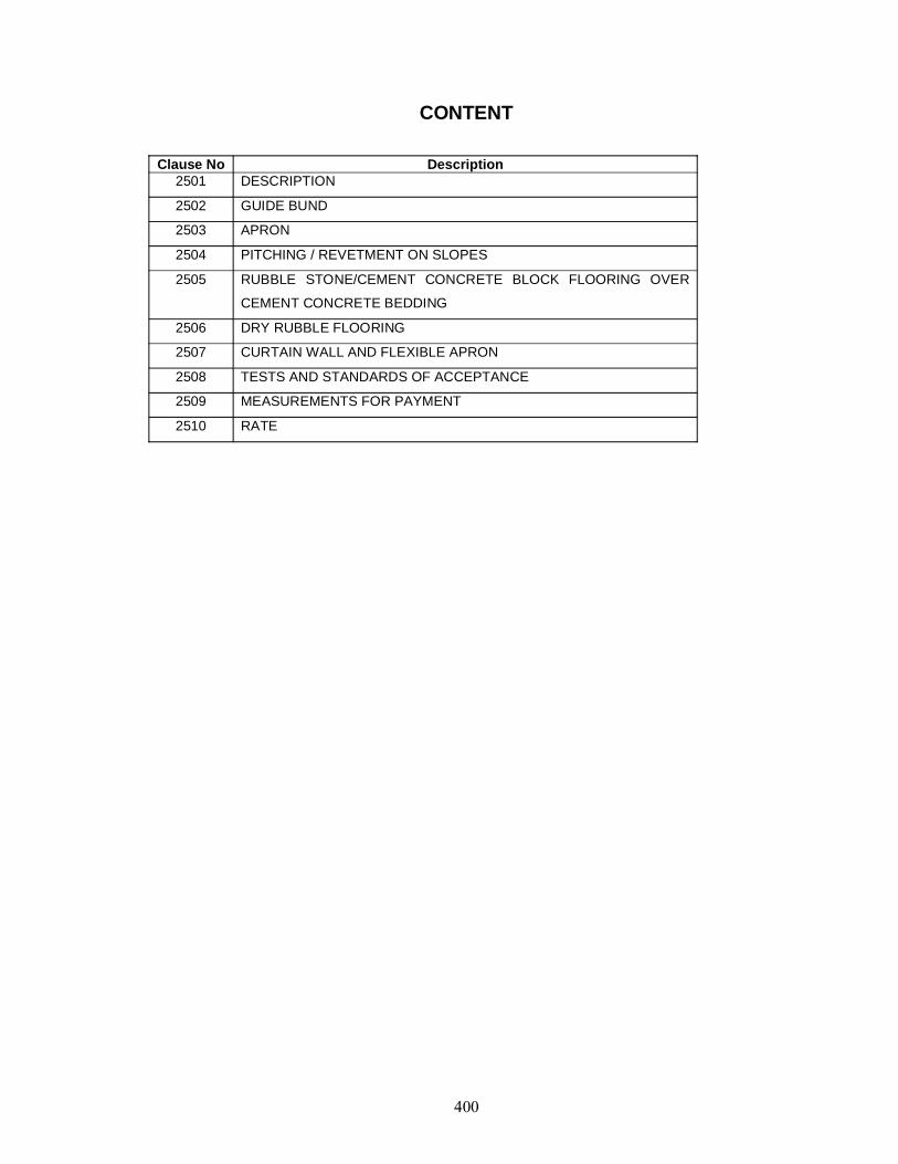
CONTENT
Clause No Description2501 DESCRIPTION
2502 GUIDE BUND
2503 APRON
2504 PITCHING / REVETMENT ON SLOPES
2505 RUBBLE STONE/CEMENT CONCRETE BLOCK FLOORING OVER
CEMENT CONCRETE BEDDING
2506 DRY RUBBLE FLOORING
2507 CURTAIN WALL AND FLEXIBLE APRON
2508 TESTS AND STANDARDS OF ACCEPTANCE
2509 MEASUREMENTS FOR PAYMENT
2510 RATE

2501 DESCRIPTIONRiver training and protection work shall include construction of guide bunds, guide walls, bank
protection, flooring and approach embankment protection as required for ensuring safety of the bridgestructure and its approaches .against damage by flood/flowing water. Construction of variouscomponents shall conform to IRC89 and these specifications or as directed by the Engineer.
2502. GUIDE BUND2502.1. This work shall consist of construction of embankment of guide bund and provision ofpitching/rivetment on slopes, apron, toe protection, curtain walls etc. as indicated on the drawing inaccordance with these specifications or as approved by the Engineer.
The provisions given hereunder are applicable only to guide bunds for bridges across alluvialrivers. Guide bunds for bridges across submontane rivers shall call for supplemental specifications.
2502.2. The alignment and layout of guide bund shall be as indicated on the drawing or as approved bythe Engineer. The construction of embankment for guide bund shall conform to provisions of Section300 of these Specifications. Pitching, filter underneath pitching and turfing, apron, toe protection, curtainwalls, etc., shall be as per these specifications.
2502.3. Guide bunds shall generally be made of locally available materials from the river bed preferablycohesionless materials. Trial pits shall be taken in borrow holes to examine suitability of soil forconstruction and also to decide the types of earth moving machinery to be arranged. The borrow pitsshould be sufficiently away from the location of the launching apron. No borrow pits should be dug onthe river side of the guide bunds.
Construction of guide bund shall be taken in hand alongwith the construction of the bridge.Every effort shall be made to complete the work of the guide bund in one working season. Where thereis any doubt about completion of the whole guide bund within one working season, suitable measuresshall be planned and executed for protection of completed work. In such cases the construction ofguide bund shall be started from abutment towards upstream.
2502.4. Construction of apron and pitching of the guide bunds shall generally conform to clause 2503and 2504 of these Specifications. Sufficient length of pit along the guide bund shall be ready within oneto two months of commencement of work so that the placing of stories in the apron and in the slopepitching can be commenced. As a guideline, earthwork should be completed within 80 per cent ofworking season and about 70 per cent working season shall be available for laying apron and pitching.No portion of the guide bund should be left below HFL before the onset of monsoon. Bottom of apronpit shall be as low as permitted by sub-soil water/lowest water level. Sufficient labour and appropriateearth moving machinery and trained staff shall be deployed in construction.
2502.5. The Contractor shall furnish his planning for approval of the Engineer regarding transport ofstones from the quarries to the site of work taking into account the quantities of stone required to betransported every day, train/truck, etc., deployed, available ferry or boats and labour available forloading and unloading and for laying within the time frame for construction of guide bund. Adequatereserve of stones should be maintained for major works as decided by the Engineer. Reserve stonesshall be stacked far away from the main channel of the river.
2502.6. Where the alignment of guide bund or the approach embankment crosses a branch channel ofthe river, the branch channel may be either diverted to the main channel of the river with the help ofspurs, etc. or closed by a properly designed closing dyke or closure bund before taking up constructionof guide bund.
2503. APRON2503.1. General
This work shall consist of laying boulders directly or in wire crates on the bed of rivers forprotection against scour.
Where the required size of boulders are not available economically, cement concrete blocks ofequivalent weight shall be used. The grade of concrete shall be M 15 nominal mix. (This holds good forpitching on slopes and flooring also). Cement concrete blocks shall be preferred where practicable.
The stones used in apron shall be sound, hard, durable and fairly regular in shape. Stonesubject to marked deterioration by water or weather shall not be used.
Quarry stones arc preferable to round boulders as the latter roll off easily. Angular stones fitinto each other better and have good interlocking characteristics.
Where the required size stones are not economically available, cement concrete blocks in M15grade conforming to Section 1700 or stones in wire crates in combination may be used in place ofisolated stones of equivalent weight. Cement concrete blocks will be preferred, wherever practicable.
2503.2. Laying Boulder ApronThe size of stone should conform to clause 5.3.7.2 of IRC:89.
The size of stone shall be as large as possible. In no case any fragment shall weigh less than40 kg. The specific gravity of stones shall be as high as possible and it shall not be less than 2,65.
To ensure regular and orderly disposition of the full intended quantity of stone in the apron,template cross walls in dry masonry shall be built about a metre thick and to the full height of thespecified thickness of the apron at intervals of 30 metres all along the length and width of the apron.Within these walls, the stone then shallbe hand packed.
The surface on which the apron is to be laid shall be levelled and prepared for the length andwidth as shown on the drawings. In case the surface on which apron is to be laid is below the low waterlevel, the ground level may be raised upto low water level by dumping earth and the apron laid thereon.The quantity of stone required in the apron shall be re-worked out by taking the toe of pitching at higherlevel.
2503.3. Laying Wire Crates and Mattresses in the Apron Wire crates shall be made from hot dippedgalvanized mild steel wire of diameter not less than 4 mm in annealed condition having tensile strengthof 300-450 MPa conforming to 1S:280. The galvanizing coating shall be heavy coating for soft conditionconforming to 15:4826.
The mesh of the crate shall not be more than 150 mm.
Wire crates for shallow or accessible situations shall be 3 metre x 1.5 metre x 1.25 metre insize. Where these have to be deposited and there is a chance of overturning, the crate shall be dividedinto 1.5 metre compartments by cross netting.
For deep or inaccessible situations, wire crates can be made smaller subject to the approval ofthe Engineer.
Wire rates built in-situ, shall not be larger than 7.5 metres x 3 metres x 0.6 metre. nor smallerthan 2 metres x 1 metre x 0.3 metre. Sides of large crates shall be securely stayed at intervals of notmore than 1 .50 metres to prevent bulging.
The netting shall be made by fixing a row of spikes on a beam at a spacing equal to the mesh.The beam must be a little longer than the width of netting required. The wire is to be cut to lengthsabout three times the length of the net required. Each piece shall he bent at the middle around one ofthe spikes arid the weaving commenced from one corner.
A double twist shall be given at each intersection. This twisting shall be carefully done bymeans of a strong iron bar, five and half turns being given to the bar at each splice.
The bottom and two ends of the crate or mattress shall be made at one time. The other twosides shall be made separately and shall be secured to the bottom and the ends by twisting adjacentvires together. The top shall be made separately and shall be fixed in the same manner as sides afterthe crates or mattress have been filled.
Wherever possible, crates shall be placed in position before filling with boulders. The cratesshall be tilled by carefully hand-paking the boulders as tightly as possible and not by merely throwing instones or boulders.
For laying of wire crates in apron of bridges, two situations arise:i) Where the crates are to be laid us deep water and have to be dumped and then joined
together.ii) Where depth of water s low or dry bed is available. In such cases, the crates can be
laid at site.
2504. PITCHING / REVETMENT ON SLOPES2504.1. Description
This work shall consist of covering the slopes of guide bunds, training works and roadembankments with stone, boulders, cement concrete blocks or stones in wire crates over a layer ofgranular material called filter. While river side slopes are given this protection against river action, therear slopes, not subjected to direct attack 01 the river, may be protected against ordinary wavesplashing by 0.3-0,6 metre thickcover of clayey or silly earth and turfed.
2504.2. Pitching/Filter media2504.2.1. Pitching : The pitching shall be provided as indicated in the drawings. The thickness and theshape of stone pitching shall be shown on the drawing.
The stone shall be sound, hard, durable and fairly regular in shape. Quarry stone should beused. Round boulders shall not be allowed. The stones subject to marked deterioration by water orweather shall not be accepted.
The size ar4 weight of stone shall conform to clause 5.3.5.1 of IRC:89. No stone, weighing lessthan 40 kg shall, however, be used. The sizes of spalls shall be a minimum of 25 mm and shall besuitable to fill the voids in the pitching.
Where the required size stones are not economically available, cement concrete blocks in Ml 5grade conforming to Section 1700 or stones in wire crates may be used in place of isolated stones ofequivalent weight. Cement concrete blocks will be preferred wherever practicable. Use of geosyntheticshas been dealt with in Section 700.
2504.2.2. Filter media : The material for the .filter shall consist of sand, gravel, stone or coarse sand. Toprevent escape of the embankment material through the voids of the stone pitching / cement concreteblocks as well as to allow free movement of water without creating any uplift head on the pitching, oneor more layers of graded materials, commonly known as a filter medium, shall be provided underneaththe pitching.
The gradation of the filter material shall satisfy the following requirements:
Provision of a suitably designed filter is necessary under the slope pitching to prevent theescape of underlying embankment material through the voids of stone pitching/cement concrete blockswhen subjected to the attack of flowing water and wave action, etc. In order to achieve this requirement,the filter may be provided in one or more layers satisfying the following criteria :
D 15 (Filter)----------------- < 5
D 85 (Base)
D 15 (Filter)4 < --------------- < 20
D 15 (Base)
D 50 (Filter)----------------- < 25
D 50 (Base)
Notes : 1. Filter design may not be required if embankment consists of CH or Ch soils withliquid limit greater than 30, resistant to surface erosion. In this case, if a layer ofmaterial is used as bedding for pitching, it shall be well graded and its D 85 size shallbe at least twice the maximum void size in pitching.
2. In the foregoing, D 15 means the size of that sieve which allows 15 per cent byweight of the filter material to pass through it and similar is the meaning of D 50 andD 85.
3. If more than one filler layer is required, the same requirement as above shall befollowed for each layer. The finer filter shall be considered as base material forselection of coarser filter.
4. The filter shall be compacted to a firm condition. The thickness of filter is generally ofthe order of 200 mm to 300 mm. Where filter is provided in two layers, thickness ofeach layer shall be 150 mm.
2504.3. Construction OperationsBefore laying the pitching, the sides of banks shall be trimmed to the required slope and
profiles put up by means of line and pegs at intervals of 3 metres to ensure regular straight work and auniform slope throughout. Depressions shall be filled and thoroughly compacted.
The filter granular material shall be laid over the prepared base and suitably compacted to thethickness specified on the drawings.
The lowest course of pitching shall be started from the toe wall and built up in courses upwards.The toe wall shall be in dry rubble masonry (uncoursed) conforming to Clause 1405.3, in case of dryrubble pitching and shall be in nominal mix cement concrete (M 15) conforming to Clause 1704.3 incase of cement concrete block pitching.
The stone pitching shall commence in a trench below the toe of the slope. Stone shall beplaced by derrick or by hand to the required length, thickness and depth conforming to the drawings.Stones shall be set normal to the slope, and placed so that the largest dimension is perpendicular to theface of the slope, unless such dimension is greater than the specified thickness of pitching.
The largest stones shall be placed in the bottom courses and for use as headers forsubsequent courses.
In hand placed pitching, the stone of flat stratified nature should be placed with the principalbedding plane normal to the slope. The pattern of laying shall be such that the joints are broken andvoids are minimum by packing with spalls, wherever necessary, and the top surface is as smooth aspossible.
When full depth of pitching can be formed with a single stone, die stones shall be laid breakingjoints and all interstices between adjacent stones shall be filled in with spalls of the proper size andwedged in with hammers to ensure tight packing.
When two or more layers of stones must be laid to obtain the design thickness of pitching, drymasonry shall be used and stones shall be well bonded. To ensure regular and orderly disposition ofthe full intended quantity of stone as shown, template cross walls in dry masonry shall be built about ametre wide and to the full height of the specified thickness at suitable intervals and all along the lengthand width of the pitching. Within these walls the stones shall be hand packed as specified.
2504.4. Toe ProtectionIn conformity with clause 5.3.7. of IRC:89, a toe wall shall be provided at the junction of slope
pitching and launching apron of a guide bund so as to protect the slope pitching from falling even whenthe apron is not laid at low water level. The toe wall shall be in dry rubble masonry (uncoursed)conforming to Clause 1405.3 in case of dry rubble pitching or pitching/ revetment with stones in wirecrates and in nominal mix cement concrete (M 15) conforming to Clause 1704.3 in case cementconcrete blocks have been used in pitching. For protection of toes of bank slopes terminating cither inshort aprons at bed levels or anchored in flooring / rocky bed, the provisions of clause 8.2.2 of IRC:89may be complied with. The relevant specifications of the protective works for individual components willbe followed,
2505. RUBBLE STONE/CEMENT CONCRETE BLOCK FLOORING OVER CEMENT CONCRETEBEDDING2505.1. This work shall consist of constructing rubble stone / c.c. block flooring laid over a cementconcrete (M 15) bedding. The floor protection will comprise rigid flooring stated above with curtain wallsand flexible apron.
2505.2. Construction OperationsExcavations for laying the bedding and floor protection works shall be carried out as per
specifications under proper supervision. Before laying the foundation and protection walls, theexcavated trenches shall be thoroughly inspected by the Engineer- in-Charge to ensure that:a) There are no loose pockets and unfilled depressions left in the trench.b) The soil at the founding level is properly compacted to true lines and level so as to have an
even bedding.c) All concrete and other elements are laid in dry bed.
Cement concrete nominal mix (grade M 15) of 300 mm thickness shall then be laid inaccordance with provisions given in Section 1700 except that the surface of the concrete shall not begiven a smooth finish. The paving work shall be embedded in green concrete.
Flooring shall consist of 150 mm thick flat stone/cement concrete blocks (Nominal mix Grade M15 conforming to Section 1700). It shall be bedded on a layer of cement mortar (1:3) prepared toClause 1304. Spalls shall be used to fill in the voids. The joints shall then be filled with cement mortarand finished neat. The stone shall break joints and the joints shall not exceed 20 mm in thickness.Spacing of jointsmay be 20 m or so. The top of flooring shall be kept to 300 mm below the lowest bed level.
2506. DRY RUBBLE FLOORINGThis work shall consist of constructing dry rubble flooring at cross drainage works for relatively
less important works.
The base for the flooring shall be prepared to the specified levels and slopes and compactedsuitably with hand rammers or other means to have an even bedding.The thickness of flooring shall be made with one stone only. The stones shall then be laid closely on theprepared base in one or more layers as specified and the bond used shall be as specified by theEngineer.
2507. CURTAIN WALL AND FLEXIBLE APRON2507.1. Curtain WallThe rigid flooring shall be enclosed by curtain walls (tied to the wing walls) with a minimum depth belowfloor level of 2 m on upstream side and 2.5 m on downstream side. The curtain wall will be in cementconcrete M 15/stone masonry in cement mortar 1:3. The rigid flooring shall be continued over the topwidth of curtain wall.
2507.2. Flexible ApronFlexible apron 1 m thick comprising loose stone boulders (weighing not less than 40 kg) shall beprovided beyond curtain walls for a minimum distance of 3 m on upstream side and 6 m on downstreamside. The work of floor protection shall be simultaneously completed alongwith the work on bridgefoundations.
2508. TESTS AND STANDARDS OF ACCEPTANCEThe materials shall be tested in accordance with these Specifications and shall meet the
prescribed criteria.
The work shall conform to these Specifications and shall meet the prescribed standards ofacceptance.
2509. MEASUREMENTS FOR PAYMENTThe protection works shall be measured as set forth below. If directed by the Engineer for
measurement, the materials may have to be stacked at site before laying and nothing extra will be paidto the Contractor for this stacking.
The earth work in construction of embankment for guide bund shall be measured in cubicmetres unless otherwise specified.
The boulders/cement concrete blocks and wire crates in apron shall be measured in cubicmetres.
The filter and stone pitching shall be measured separately in cubic metres unless otherwisespecified.
Rubble stone/cement concrete blocks, flooring and cement concrete bedding shall bemeasured in cubic metres for each class of material.
Preparation of base for laying the flooring shall be deemed incidental to the work.
For laying apron, excavation upto an average depth of 150 mm shall be deemed to be includedin the main item and shall not be measured separately unless otherwise specified. Excavation morethan 150 mm shall be measured in cubic metres as given in Clause 304.
2510. RATEThe contract unit rate for the construction of embankment for guide bund shall cover the cost of
all materials including transportation, laying, compacting, all labour, tools, equipment, sampling andtesting, supervision and all incidentals necessary for completing the work according to thesespecifications.
The contract unit rate for one cubic metre of finished work of apron shall include the cost of allmaterial, labour, tools and plant for completing the work according to above specifications. Excavationupto an average depth of 150 mm shall also be deemed to be included in the rate as dressing of thebed. Excavation beyond this depth shall be paid for separately unless otherwise specified. The contractunit rate for one cubic metre of filter or stone/cement concrete block pitching on slopes shall include thecost of preparing the bases, putting to the profiles, laying and compacting the filter and stone pitching ofdry rubble/cement concrete block rivetment for embankment slopes to the specified thickness, lines,curves, slopes and levels and all labour and materials as well as tools and plant required for the work.The contract unit rate for rubble stone/cement concrete block flooring shall include the cost of allmaterial, labour and tools and plant for completing the work as per these specifications.

2600 Expansion Joints
CONTENT
Clause No Description2601 DESCRIPTION
2602 GENERAL
2603 REQUIREMENTS
2604 STEEL PLATE SLIDING EXPANSION JOINTS
2605 FILLER JOINTS
2506 ELASTOMERIC SLAB SEAL EXPANSION JOINT
2607 STRIP SEAL EXPANSION JOINT
2608 TESTS AND STANDARDS OF ACCEPTANCE
2609 MEASUREMENTS FOR PAYMENT
2610 RATE
2601. DESCRIPTION
This work shall consist of fabrication and placing of expansion joints as indicated on the drawing andconforming to these specifications or as directed by the Engineer.
2602. GENERAL
a) The expansion joints shall be designed and duly got approved by the Engineer. It hall cater forexpected movement and rotation of the structure at the joints and provide mooth riding surface. Itshall also be easy for inspection maintenance and replacement
b) Expansion joints shall be robust, durable, water-light and replaceable. Site fabricated expansionjoints shall be prohibited. Expansion joints shall be obtained by the Engineer either directly orthrough the Contractor from approved manufacturers and be of proven type.
c) For bridges with prestressed concrete superstructure, with individual span length more than 20 m orbuilt with innovative design/construction elastomeric expansion joints of slab seal or strip seal typeshall be provided.
d) For slab type of bridges of spans less than 10 metres continuous surfacing may be provided acrossthe expansion gaps, supported on a -20 mm thick plate placed and fixed at the level of the deckslab.
e) For bridges other than those mentioned in (c) above with spans above 10 metres, an alternativespecification of sliding steel plate joint or filled joints with copper plates may also be adopted ifapproved by the Engineer, apart from elastomeric expansion joint of slab seal or strip seal type.
f) Vehicular traffic shall not be allowed over expansion joints after its construction for such period asmay be determined by the Engineer.
g) Proprietary type deck joints offered by the Contractor in lieu of the type specified shall comply in allrespects with the manufacturer’s specifications and meet the required range of movements androtations and be fit for the purpose of ensuring satisfactory long term performance in the bridge.
Where alternative type proprietary deck joints are proposed by the Contractor, the following informationshall be provided.
i) Name and location of the proposed manufacturer.
ii) Dimensions and general details of the joint including material specifications, holding down bolt oranchorage details and installation procedures.
iii) Evidence of satisfactory performance under similar environmental conditions of similar joints beingproduced by the manufacturer.
Any acceptance of alternative types will be at the sole discretion of the Engineer.
Such deck joints shall be installed in accordance with the manufacturer’s recommendations and to thegeneral requirements of this Specification.
No expansion joint shall be provided only for the width of the carriageway. It shall follow the profileincluding the kerb and the footway and facia, if provided. The type of expansion joint for the latter maybe made different from that used for the carriageway expansion joint.
2603. REQUIREMENTS
2603.1. The requirement criterion will be separately applicable for the expansion joint proper and thetransition zone of attachment to the deck.
2603.2. There are two types of performance requirements for the expansion joint proper viz. from thenecessity of the bridge and from the road users e.g. man, animal and vehicle.
2603.3. Performance Requirement with Respect to Bridges
The expansion joint shall:
a) Withstand the imposed load including the impact load from live load and other sources.
b) Allow expansion and contraction movement due to temperature, creep, shrinkage, prestressing andstructural deformations.
c) Permit relative rotation in elevation and plan due to the causes as noted above,
d) Be waterproof. Bridge deck expansion joint seals play a critical rol e in preventing the degradation ofthe structural components of the bridge system. Without effective joint seals, water passes throughthe bridge deck and works harmfully to corrode steel components and cause deterioration of theconcrete. Rain water gathers various corroding additives from the atmosphere and also from thecarriageway.
e) Ensure sealing. In case bridge deck joints arc not sealed, apart from loss of waterproofing, grit andother forms of road debris may enter the joint. Debris, when impacted with the joint can seriouslyrestrict the movement instead of facilitating the same. In the case of proprietary joints beingaccepted for adoption, the sealing shall be as specified by them,
f) Ensure long life by being resistant to corrosion,
g) Be easy to install,
h) Be easy to maintain. Replace ability of expansion joint shall be one of the basic criteria for selectionof type of expansion joint,
i) Be resistant to the materials likely to collect/spill over the deck in its normal service.
2603.4. Performance Requirement with Respect to User
The expansion joint snail:
a) Provide smooth continuity at the top of the deck for riding comfort,
b) Be of skid resistant surface,
c) Be non-damaging to the rubber tyre,
d) Make minimum noise during vehicular crossing.
e) Ensure that animal paws and hooves should not get entangled where bridges are used by animaldrawn traffic,
f) Permit passing of bullock Cart steel tyre for bridges where bullock cans ply,
g) Look good aesthetically.
2603.5. Performance Requirement for Transition ZoneIt is the zone of connection of joint assembly and the adjoining deck.
The expansion joint shall:
a) Permit transfer of generated forces without distress, i.e... Without getting uprooted. The purpose willnot be served if the bonding is with the wearing COM only. Anchorage must be provided with thedeck structural element.
b) Ensure that surface in the transition zone slays undisturbed during long term service.
2604. STEEL PLATE SLIDING EXPANSION JOINTS
a) In this type of buried joint, the wearing coat shall be made continuous over the joint. The otheralternative shall be to keep a gap in the wearing coal which is filled up with a seal and filler, to beprovided in extremely hoi areas.
b) Materials for steel plates shall conform to Section 1900. The exposed metallic components shall begalvanized or coaled with approved anti-corrosive paint. The thickness shall be 20 mm or so forobtaining satisfactory performance.
c) Plates shall be placed to the line, grade and expansion gap shown on the drawings with anyadjustment required for temperature, particular care being taken with the top of the plates.
d) Plates shall be firmly held in place during concreting by methods approved by the Engineer,
e) Any temporary bolls or other fixings which prevent relative movement of the adjacent pans of thejoint shall be removed as soon is the concrete has set sufficiently to hold the expansion plates intheir correct positions. In any case, temporary bolts or other fittings shall be removed within 6 hoursof placing concrete unless otherwise directed by the Engineer.
f) Care shall be taken to prevent damage to expansion joint plates or its coating.
g) If any damage occurs the plates and coatings shall be restored by the Contractor to the satisfactionof the Engineer.
h) Plates shall be free of oil, rust, loose paint or other similar material before coating.
2605. FILLER JOINTS
a) The components of this type of joint shall be at least 2 mm thick corrugated copper plate placedslightly below the wearing coat, 20 mm thick compressible fibre board to protect the edges. 20 mm
thick premoulded joint filler Tilling the gap upto the lop level of the wearing coat, sealed with a jointscaling compound.
b) The material used for filling expansion joint shall be bitumen impregnated fell, clastomer or anyother suitable material, as specified on the drawings. Impregnated felt shall conform to therequirements of 1S:1838, and shall be got approved from the Engineer, The joint filler shall consistof large pieces and assembly of small pieces to make up the required size shall be avoided.
c) Expansion joint material) shall be handled with care and stored under cover by the Contractor toprevent damage.
d) Any damage occurring after delivery shall be made good to the satisfaction of the Engineer and atthe expense of the Contractor.
e) Joint gaps (hall be constructed as shown on the drawings, Surfaces of joint grooves shall bethoroughly cleaned with a wire brush to remove all loose materials and dirt and debris, then washedor jelled out.
f) Pre-moulded expansion joint filler shall not be placed in position until immediately prior to theplacing of the abutting material. If the two adjacent surfaces of the joint are to be placed at differenttimes, this type of joint filler shall not be placed until the second fact is about to be placed.
g) Sealants shall be installed in accordance with the manufacturer’s recommendations and allappropriate requirement;! For joint face priming,
h) Sealants shall be finished approximately 3 mm below the upper surfaces of the joint,
i) Joint materials spill or splashed onto finished surfaces of the bridge during joint filling operationsshall be removed and the surfaces made good to the Engineer’s approval.
j) No joint shall be sealed until inspected by the Engineer and approval is givers to proceed with thework.
2606. ELASTOMERIC SLAB SEAL EXPANSION JOINT
2606.1. Materials
a) Steel inserts shall conform to IS: 226. Use of any other materials like fiberglass or similar materialshall not be permitted.
b) Elastomer for elasiomeric slab unit (ESU) shall conform to clause 915.1 of KC: S3 (Pan 11),compounded to give hardness 1RHD 60 +5, subject to the following additional stipulations:
i) Chloropiene (CR) only shall be used in the manufacture of elasiomeric expansion joints. Noreclaimed/natural rubber or vulcanised wastes shall be used.
ii) The chloroprene material used in the manufacture of elastomeric (expansion joints) shall beNeoprene WRT. Bayprene 110, Skyprene B5 or Denka S- 40V.
iii) Chloroprene content of the compound shall not be lower than 60 petcent by weight. The ashcontent shall not exceed 5 pr cent (»s per tests conducted in accordance with ASTM D-297 for (i)and (ii) above.
iv) EPDM and other similar candidate elastomers for expansion joints shall not be permitted.
c) Elasiomeric plugs,
d) Spacer bars, marked with centre to centre distance of fixing holes.
e) Fixing bolts and nuts made of stainless steel.
f) Anchor bars comprising hooked anchor stiffeners welded with tower steel inserts and sinusoidalanchor bars welded with horizontal leg of the edge steel inserts. The elaborate anchoringarrangements of steel inserts shall be permanently welded tied with the steel reinforcement
2606.2- Fabrication
a) Steel inserts shall be grit blasted and provided with epoxy paint.
b) Edges of reinforcing steel sections shall be founded.
c) Expansion joints shall be fully moulded to the required size in one single vulcanising operationincluding the encasing layers as integral and homogeneous part.
d) Tolerances of fabrication shall be as follows:
i) Plan dimension -> ± 5 mmii) Total height -> ± 3 mm
2606.3. Supply and Handling
i) The Contractor shall supply all steel-reinforced elasiomeric expansion joints including bolts, nuts,sealant, plugs and all other accessories for the effective installation of the joints including angledjointing sections for kerbs.
ii) Expansion joint material shall he handled with care and stored under cover by the Contractor toprevent damage. Any damage occurring after delivery shall be made good at the expense of theContractor to the satisfaction of the Engineer.
2606.4. Installation
2606.4.1. Expansion joints shall be installed as per approved drawing. Steel inserts, spacer bars,concreting of pockets, fixing of elastomer slab unit and presetting, etc., shall be done as per hefollowing:
a) Steel Inserts
i) Deck casting shall be done leaving pockets or recess for steel inserts and anchors of theexpansion joint as per drawing.
ii) Steel inserts shall be lowered at the appropriate location inside the pocket
iii) The top of the insert shall be flush with the finished level of wearing course maintaining thecamber.
iv) Spacer bars, duly set appropriately to the month of installation, shall be filled under propersupervision.
v) Anchor rods shall be lied/welded with the existing deck main reinforcement, maintaining leveland alignment.
vi) Welding between anchor rods and deck reinforcement is preferable. If welding is not possible,strong steel tie wires shall be used for fastening, under proper supervision,
b) Spacer Bar
i) Spacer bars shall be used to ensure proper positioning of bolts and also leveling of the steelinserts during fixing of the same with the deck reinforcement and casting second stage concretingin the pocket thereafter.
ii) The 2nd stage concreting operation shall preferably be started within 24 hours of fixing the steelinserts. In such cases, spacer bars should be removed just after concreting is finished. If there isa substantial time lag between fixing of inserts and concreting, then any one of the followingmethods shall be adopted, depending on the support condition:
a) For simply supported bridge resting on simple elasiomeric bearings, (with no dowel pins),insert shall be placed in position with spacer bars at every alternate joints. Such joints shall becalled restrained joints hereafier. In other words, inserts shall not be fixed simultaneously at twoends of one span. If the above condition is satisfied, inserts with spacer bars shall be kepi inposition for a substantially longer period at such restrained joints. Spacer bars shall beremoved after concreting of such restrained joints and inserts placed in position with spacerbars at the other unrestrained joints thereafter.
b) For bridges resting on other than elasiomeric bearings (including bearings with dowel pins atone end), after placing and aligning the inserts and securing the same, the spacer bars shall beremoved Concreting shall be done with great care so that inserts are not dislocated ordistorted.
iii) While removing the spacer bar after concreting, one must lake care to see that the concrete isnot damaged during withdrawal of spacer bar. If the spacer bar happens to be snugly fitted, itshall not be pulled by any means; it shall be gas cut in two pieces and then removed.
c) Concreting of Pocket
i) Concreting of pocket shall be done with great care using proper miconforming 10 grade similar tothat of the deck casting besides ensuring efficient bonding between deck and steel insert. Alsoproper care shall be given for ensuring efficient bonding with the already cast concrete.
ii) Needle vibrators shall be used. Care shall be taken so that the position of steel insert is notdisturbed during vibration.
iii) Spacer bar shall be removed within an appropriate lime before the joint is required to permitmovement,
d) Riling of Elstomeric Slab Unit (ESU)
i) Special jig shall be used to preset the ESU during installation
ii) ESU (mounted on the jig. if preset) shall he lowered to position.
iii) The line and level on the ESU should be adjusted.
iv) ESU shall be removed and coated with special adhesive
v) ESU shall be placed in position again, ensuring waterproof joining at required faces.
vi) ESU shall be tightened with stainless steel nuts and lock washers in position. Tightened nuts shallbe locked with lock washers.
vi) Special sealant shall be poured inside the plug holes.
vii) The elastomeric plugs shall be pressed in position after applying adhesive on the appropriatesurface.
viii) ESU shall be fitted in position after completion of wearing course. While completing this part ofthe wearing course, adequate care shall be taken to ensure a waterproof joining with the alreadyexisting wearing course,
e) Pre-Setting
i) The main purpose of presetting of the steel inserts at the time of its installation is to ensure asclosely as possible the condition that in the long run at the mean average annual temperature, theESU remains at its nominal state.
ii) Major factors responsible for changing the longitudinal length of the bridge superstructure areindicated below:
a) Temperature variation from annual mean.
b) Changes due to shrinkage of concrete.
c) Changes due to elastic shortening and creep of the prcstressed bridge superstructure.
d) Deformation of superstructure and substructure, if any. Resultant changes in expansion gap dueto first factor can occur in both directions from any pre-selected mean position whereas changesdue lo creep and shrinkage are unidirectional such that the expansion gap continuously increaseswith passage of time. The steel insert unit of expansion joint can be fixed in any month of theyear. As stated earlier, the expansion gap between bridges superstructures may vary from time totime; hence the initial fixing distance between fixing points will obviously depend on the month ofinstallation of steel insert. The c/c distance between stainless steel fixing of bolts as indicated inthe drawing can be taken as only nominal. The same shall be modified by presetting dependingon:
i) The difference between the mean temperature of the month of fixing of steel insert and the annualaverage temperature.
ii) The elapsed period between the casting and/or prestressing and fixing of steel insert forcalculating the remnant creep and shrinkage.
2606.4.2. Special requirements for installation
i) Prior to construction of bridge deck area adjacent lo the joint, the supplier shall provide detailedworking drawings showing the location of all bolts, recesses and holes necessary for theinstallation of the joint. Reinforcing bars in superstructure shall be amended as required to ensurethat there will be no interference in the installation of the joint.
ii) All bearing surfaces and recesses which are in contact with the joint assembly shall be checked witha straight edge to ensure flatness of profile.
iii) No holes shall be drilled for fixing bolts within 7 days of concreting. Holes for the bolts shall be drilledlo the size and depth shown on the drawings,
iv) Sections of the jointing making the completed joint shall follow a straight line.
v) The fixing bolts shall not be placed in a position until al least 4 weeks after stressing is completed inpost-tensioned box or beam and slab structures. Prior To placing sections of jointing, contactsurfaces shall be cleaned lo remove all grease, tar, paint, oil, mud or any other foreign material thatmay affect adhesion of the sealant.
vi) Sealant shall only be applied lo dry contact surfaces. Sufficient sealant shall be applied to thecontact surfaces lo cause extrusion of sealant when the jointing is fixed in position.
vii) Final sealing of the finished expansion joint shall be completed immediately after completion ofinstallation. All exposed ends, joints between units and other areas of possible leakage shall befilled with sealant. All voids between the sides of the jointing and concrete or plates shall be filledwith sealant.
viii) Boll cavities shall be cleaned and plugged with neoprene cavity plugs. Prior to placing the plugssufficient sealant shall be placed in the cavities lo cause extrusion of the sealant by the plugs.
ix) All excess sealant shall be removed from the jointing and adjacent areas.
2606.5. Acceptance Test
2606.5.1. As per clause 918.7 of IRC-83 (Part II), necessary quality control certification by themanufacturer in regard to properties of Elastomer and steel will be furnished.
For severe environment, ozone resistance test as per clause 915.2.3 of IRC: 83 (Part II), shall becarried out for elastomer.The properties of the elastomer shall conform to Table I of clause 915.2 ofIRC: 83(Part II).Theacceptance testing for elastomer, material shall conform to clause 918.4.1.2 of IRC: 83 (Part II) withadditional criteria as stated in Clause 2005.
2606.5.2. The fabricated expansion joint / shall be- subjected to the following acceptance tests:
i) Routine lest. Each expansion joint shall be tested- for at least 100 cycles for a test movement whichshall be 10 per cent mom than the design expansion contraction movement
ii) In addition to routine test, one out of every 20 expansion joints shall be subjected to the testmovement for 4000 cycles. The lot shall be rejected if the elastomer material shows signs of fatigueor permanent set or distress in the test, the test piece shall not be used in the
iii) The type test for abrasion resistance shall be carried out for one joint out of every 20 not, as per IS:34QQ (Part1 3) and the standard deviation shall be within ± 20 per cent
N.B, the manufacturer shall preferably have in-house testing facility. Otherwise, the testing shall be gotdone by him at his expense at any testing establishment selected by the Engineer, A manufacturer whocannot cany out the acceptance test shall not be entitled to supply elastomeric slab seal joint.
2607. STRIP SEAL EXPANSION JOINT
2607.1. Components
Strip seal expansion joint shall comprise the following items:
a) Edge beams - This special claw leg profiled member shall be of extruded rolled steel sectioncombining good weld ability with notch toughness.
b) Strip seal - This shall be of chloroprene with high tear strength, insensitive to oil, gasoline, andozone. U shall have high resistance to aging. This component, provided to ensure water lightness,shall have bulbous shape of the part of the seal which is inserted into the groove, provided in theedge beam. The sea) should be vulcanised b single operation for minimum full length of joint,
c) Rigid Anchorage - This shall be welded to the edge beam at staggered distance.
d) Anchor loops - This shall be made of weld able steel connecting the rigid anchorage with deckreinforcement 2607.2. Material
a) Edge beam) of this special section are at present being directly imported in India. The steel shallconform to steel grade Rs t 37-2 of Gentian Standard or equivalent
b) Chloroprene of strip seal shall conform to clause 915.1 of RC:83 (Pan II). The properties ofchloroprene shall conform to Table 2600-1.
c) Anchorage steel shall conform to IS: 2062.
d) Anchor loop shall conform to IS: 2062.
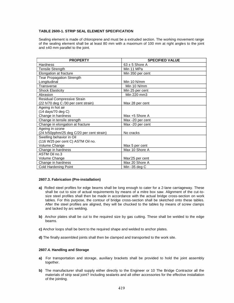
TABLE 2600-1. STRIP SEAL ELEMENT SPECIFICATION
Sealing element is made of chloroprene and must be a extruded section. The working movement rangeof the sealing element shall be at least 80 mm with a maximum of 100 mm at right angles to the jointand ±40 mm parallel to the joint.
PROPERTY SPECIFIED VALUEHardness 63 ± 5 Shore ATensile Strength Min 11 MPaElongation at fracture Min 350 per centTear Propagation StrengthLongitudinal Min 10 N/mmTransverse Min 10 N/mmShock Elasticity Min 25 per centAbrasion Min 220 mm3Residual Compressive Strain(22 h/70 deg C /30 per cent strain) Max 28 per centAgeing in hot air(14 days/70 deg C)Change in hardness Max +5 Shore AChange in tensile strength Max -20 per centChange in elongation at fracture Max -20 per centAgeing in ozone(24 h/50pphm/25 deg C/20 per cent strain) No cracksSwelling behavior in Oil(116 W25 per cent C) ASTM Oil no.Volume Change Max 5 per centChange in hardness Max 10 Shore AASTM Oil no.3Volume Change Max’25 per centChange in hardness Max 20 Shore ACold Hardening Point Min -35 deg C
2607.3. Fabrication (Pre-installation)
a) Rolled steel profiles for edge beams shall be long enough to cater for a 2-lane carriageway. Theseshall be cut to size of actual requirements by means of a mitre box saw. Alignment of the cut-to-size steel profiles shall then be made in accordance with the actual bridge cross-section on worktables. For this purpose, the contour of bridge cross-section shall be sketched onto these tables.After the steel profiles are aligned, they will be chucked to the tables by means of screw clampsand lacked by arc welding.
b) Anchor plates shall be cut to the required size by gas cutting. These shall be welded to the edgebeams.
c) Anchor loops shall be bent to the required shape and welded to anchor plates.
d) The finally assembled joints shall then be clamped and transported to the work site.
2607.4. Handling and Storage
a) For transportation and storage, auxiliary brackets shall be provided to hold the joint assemblytogether.
b) The manufacturer shall supply either directly to the Engineer or 10 The Bridge Contractor all thematerials of strip seal joint? Including sealants and all other accessories for the effective installationof the jointing.
c) Expansion joint material shall be handled with care; it shall be stored under cover on suitable lumberpadding by the Contractor to prevent damage. Any damage occurring after delivery shall be madegood at the Bridge Contractor’s expense to the satisfaction of the Engineer.
2607.5. Installation
2607.5.1. The width of the g ap to cater for movement due to thermal effect, prestress, shrinkage andcreep, superstructure deformations (if any) and sub-structure deformations (if any) shall bedetermined and intimated to the manufacturer. Depending upon the temperature at which the jointis likely to be installed, the gap dimension shall be preset.
2607.5.2. Taking the width of gap for movement of the joint into account, the dimensions of the recessin the decking shall be established in accordance with the drawings or design data of themanufacturer. The surfaces of the recess shall be thoroughly cleaned and all dirt and debrisremoved. The exposed reinforcement shall be suitably adjusted to permit unobstructed lowering ofthe joint into the recess.
2607.5.3. The recess shall be shut tered in such a way that dimensions in the joint drawing aremaintained. The formwork shall be tight.
2607.5.4. Immediately prior to placing the joint, the presetting shall be inspected. Should the actualtemperature of the structure be different from the temperature provided for presetting, correction ofthe presetting shall be done. After adjustment, the brackets shall be tightened again,
2607.5.5. The joint shall be lowered in a pre-determined position. Following placement of the joint in theprepared recess, the joint shall be leveled and finally aligned and the anchor loops on one side ofthe joint welded to the exposed reinforcement bars of the structure. Upon completion, the sameprocedure shall be followed for the other side of the joint. With the expansion joint finally held atboth sides, the auxiliary brackets shall be released, allowing the joint to lake up the movement ofthe structure.
2607.5.6. High quality concrete shall then be filled into the recess. The packing concrete must featurelow shrinkage and have the same strength as that of the superstructure, but in any case not lessthan M 35 grade. Good compaction and careful curing of concrete is particularly important. After theconcrete has cured, the movable installation brackets still in place shall be removed,
2607.5.7. Rolled up neoprene strip seal shall be cut into the required length and inserted between theedge beams by using a crow bar pushing the bulb of the seal into the steel grooves of the edgebeams. A landing to a bead shall be formed in the thickened end of the edges of the seal whichwould force the thickened end against the steel beam due to wedge effect when the strip seal isbuttoned in place.
2607.5.8. As soon as the concrete in the recess has become initially set, a sturdy ramp shall be placedover the joint to protect the exposed steel beams and neoprene seals from site traffic. Expansionjoint shall not be exposed to traffic loading before the carriageway surfacing is placed.
26073.9. The carriageway surfacing shall be finished flush with the top of the steel sections. The actualjunction of the surfacing/wearing coat with the steel edge section shall be formed by a wedgeshaped joint with a sealing compound. The horizontal leg of the edge beam shall be cleanedbeforehand. It is particularly important to ensure thorough and careful compaction of the surfacingin order to prevent any premature depression forming in it.
Acceptance Test
i) All steel elements shall be finished with corrosion protection system.
ii) For neoprene seal, the acceptance test shall conform to the requirements stipulated in Table 2600-1It shall also be stretch tested. If a manufacturer is to supply this type of joint, they will have toproduce a test certificate accordingly conducted in a recognised laboratory, in India or abroad.
iii) In view of the importance of the built up edge beams, special investigation of fatigue strength of thissection with anchorages to withstand 2 \ \Cf load change cycles without showing signs of damage,will be required. The supplier shall have to produce a test certificate in this regard, conducted in arecognised laboratory, in India or abroad.
iv) The manufacturer shall produce test certificates indicating that anchorage system had been testedin a recognised laboratory to determine optimum configuration of anchorage assembly underdynamic loading.
v) The manufacturer shall satisfy the Engineer that water tightness test for the type of joint has beencarried out in a recognised laboratory to check the water tightness under a water pressure of 4bars.
vi) As strip seal type of joint is specialized in nature, generally of the proprietary type, the manufacturershall be required 10 produce evidence of satisfactory performance of this type of joint.
2608. TESTS AND STANDARDS OF ACCEPTANCE
The materials shall be tested in accordance with these specifications and shall meet the prescribedcriteria. The work shall conform to these specifications and shall meet the prescribed standards ofacceptance.

2609. MEASUREMENTS FOR PAYMENTThe expansion joint shall be measured in running meters. For filled joints, the rate per running metreshall include the cost of sealant for the depth provided in this drawing.
2610. RATEThe contract unit rate shall include the cost of all material, labour, equipment and other incidentalcharges for fixing the joints complete in all respects as per these specifications in the case of BridgeContractor supplying the expansion joint. If the manufacturer supplies the expansion joint directly to theEngineer, the cost of installation, handling and fixing shall be borne by the Bridge Contractor.

2700 Wearing Coat and Appurtenances

CONTENT
Clause No Description2701 DESCRIPTION
2702 WEARING COAT
2703 RAILINGS
2704 APPROACH SLAB
2705 DRAINAGE SPOUTS
2706 WEEP HOLE
2707 TESTS AND STANDARDS OF ACCEPTANCE
2708 MEASUREMENTS FOR PAYMENT
2709 RATE
2701. DESCRIPTIONThis work shall include wearing coat and bridge appurtenances such as railing, approach slab, drainagespouts, weep holes in conformity with details shown on the drawing and these specifications or asapproved by the Engineer.
2702. WEARING COAT2702.1. Bituminous Wearing Coat
Specifications for bituminous concrete/bitumen mastic in wearing coat shall conform to Section500 except for the special requirements as stated hereinafter.
2702.1.1. Principles of bituminous wearing coat shall comprise the following:i) A layer of mastic asphalt, 6 mm thick after applying a prime coat over the top of the deck
before the wearing coat is laid. The prime coat and the layer of mastic asphalt shall belaid as per Clauses 503 and 515 respectively.
ii) 50 mm thick asphaltic concrete wearing coat in two layers of 25 mm each as per Clause512.
In case of high rainfall intensity areas, the thickness of mastic asphalt layer may be increasedto 12 mm.
2702.1.2. For high traffic density, an alternative specification for wearing course comprising 40 mmbituminous concrete overlaid with 25 mm thick bitumen mastic layer can be adopted. The work shall bedone in conformity with Section 500.
2702.2. Cement Concrete Wearing CoatCement concrete wearing coat may be provided in case of isolated bridge construction or bridgeslocated in remote areas. It shall not be laid monolithic with the deck.
The thickness of wearing coat shall be 75 mm. The minimum grade of concrete shall be M 30with water cement ratio as 0.4. Curing of wearing coat earlier than what is generally required may beresorted to, so as to avoid formation of shrinkage cracks in hot weather.
All carriageway and footpath surfaces shall have non -skid characteristics.
The cross slope in the deck shall be kept as 2.5 per cent for decks, level in longitudinal profile.
2702.3. For providing cross camber no variation in thickness of wearing coat shall be permitted,
2703. RAILINGS2703.1. General
a) Bridge railing includes the portion of the structure erected on and above the kerb for theprotection of pedestrians and traffic,
b) Railings shall not be constructed until the centering false work for the span has beenreleased and the span is self-supporting. For concrete with steel reinforcement,specifications of the items of controlled concrete and reinforcement mentioned underrelevant sections of this specifications shall be applicable.
c) The type of railing shall be carefully erected true to line and grade. Posts shall be verticalwith a tolerance not to exceed 6 mm in 3 metres. The pockets left for posts shall be filledup with non-shrink able mortar.
d) The type of railing to be constructed shall be as shown On the drawings.e) Care shall be exercised in assembling expansion joints in the railings ID ensure that they
function properly.f) The bridge railings shall be amenable to quick repairs.g) Railing materials, particularly metal railings, shall be handled and stored with care, so
that the material and parts art kepi clean and free from damage. Railing materials shallbe stored above the ground on platforms, skids, or other supports and kept free fromgrease, din and other contaminants. Any material which is lost, stolen or damaged afterdelivery shall be replaced or repaired by the Contractor. Methods of repair shall notdamage the material or protective coating.
2703.2. Metal RailingsMaterials, fabrication, transportation, erection and painting for bridge railings shall conform to
the requirements of section 1900.
All complete steel rail elements, pipe terminal sections, posts, bolts, nuts, hardware and othersteel fittings shall be galvanised or painted with an approved paint.
If galvanised, all elements of the railing shall be free from abrasions, rough or sharp edges, andshall not be kinked, twisted or bent. If straightening is necessary, it shall be done by methods approvedby the Engineer.
Damaged galvanised surfaces, edges of holes and ends of steel railing cut after galvanisingshall be cleaned and re-galvanised.
The railing shall be carefully adjusted prior to fixing in place to ensure proper matching atabutting joints and correct alignment and camber throughout their length. Holes for field connectionsshall be drilled with the railing in place in the structure at proper grade and alignment.
Unless otherwise specified on the drawings, metal railing shall be given one shop coat of paintand three coats of paint after erection if sections are not galvanised.Railings shall not follow any irregularity in the alignment of the deck. When shown on the drawings, therail elements shall be curved before erection.
2703.3. Cast-in-Situ Concrete RailingsThe portion of the railing or parapet which is to be cast in place shall be constructed in
accordance with the requirements for Structural Concrete in Section 1700. The reinforcement shallconform to Section 1600.
Forms shall either be of single width boards or shall be lined with suitable material dulyapproved by the Engineer. Form joints in plane surfaces will not be permitted.
All mouldings, panel work and bevel strips shall be constructed according to the details shownon the drawings. All comers in the finished work shall be true, sharp and clean -cut and shall be freefrom cracks, spalls or other defects. Casting of posts shall be done in single pour.
2703.4. Precast Concrete RailingsPrecast members for railings shall be of reinforces cement concrete and shall conform to the
specifications given in Sections 1600 and 1700. The maximum size of the aggregate shall be limited to12 mm and the concrete grade shall be M 30. The precast members shall be removed from th e mouldsas soon as practicable and shall be kept damp for a period of at least 10 days. During this period theyshall be protected from sun and wind. Any precast member that becomes chipped, marred or crackedbefore or during the process of placing shall be rejected. Special care shall be taken u: which thesurface of the cast-m-situ portion of the deck.
2704. APPROACH SLABReinforced concrete approach slab covering the entire width of the roadway shall be provided
as per details given on the drawings or as approved by the Engineer. Minimum length of approach slabshall be 3.5 m and minimum thickness 300 mm.
The cement concrete and reinforcement shall conform to Sections 1700 and 1600 respectively.The base for the approach slab shall be as shown on the drawings or as directed by the Engineer.
2705. DRAINAGE SPOUTS2705.1. This work shall consist of furnishing and fixing in position of drainage spouts and drainagepipes for bridge decks.
Drainage along longitudinal direction shall be ensured by sufficient number of drainage fixturesembedded in the deck slab. The spouts shall be of not less than 100 mm in diameter and shall be ofcorrosive resistant material such as galvanised steel with suitable cleanout fixtures. The spacing ofdrainage spouts shall not exceed 10 m. The discharge from drainage spout shall be kept away from the
deck structure. In case of viaducts in urban areas, the drainage spouts should be connected withsuitably located pipelines to discharge the surface run-off to drains provided at ground level.
2705.2. FabricationThe drainage assembly shall be fabricated to the dimensions shown on the drawings; all
materials shall be corrosion resistant; steel components shall be of mild steel conforming to IS:226. Thedrainage assembly shall be seam welded for water tightness and then hot-dip galvanised.
2705.3. PlacementThe galvanised assembly shall be given two coats of bituminous painting before placement.
The whole assembly shall be placed in true position, lines and levels as shown in the drawing withnecessary cut-out in the shuttering for deck slab and held in place firmly.
Where the reinforcements of the deck are required to be cut, equivalent reinforcements shall beplaced at the corners of the assembly.
2705.4. FinishingAfter setting of the deck slab concrete, the shrinkage cracks around the assembly shall be
totally sealed with polysulphide sealant or bituminous sealant as per 15:1834 and the excess sealanttrimmed to receive the wearing coat. After the wearing coat is completed, similar sealant shall befinished to cover at least 50 mm on the wearing coat surface all round the drainage assembly.
2706. WEEP HOLEWeep holes shall be provided in solid plain concrete/reinforced concrete, brick/stone masonry,
abutment, wing wall and return walls as shown on the drawing or directed by the Engineer to drivemoisture from the back filling. Weep holes shall be provided with 100 mm dia AC pipe for structures inplain/reinforced concrete or brick masonry. In case of stone masonry, weep holes shall be 80 mm wide,150 mm high or circular with 150 mm diameter. Weep holes shall extend through the full width ofconcrete/masonry with slope of about 1 vertical :20 horizontal towards the draining face. The spacing ofweep holes shall generally be 1m in either direction or as shown in the drawing with the lowest at about150 mm above the low water level or ground level whichever is higher or as directed by the Engineer.
2707. TESTS AND STANDARDS OF ACCEPTANCEThe materials shall be tested in accordance with these Specifications and shall meet the
prescribed criteria.
The work shall conform to these Specifications and shall meet the prescribed standards ofacceptance.
2708. MEASUREMENTS FOR PAYMENTThe measurement for payment for wearing coat, railings and approach slab shall be made as
given below:i) Cement concrete wearing coat shall be measured in cubic metres. Asphaltic concrete
wearing coal shall be measured in square metres.ii) Railings shall be measured in running metres.iii) Approach slab and its base shall be measured separately in cubic metresiv) Drainage spouts shall be measured in numbers.v) Weep holes in concrete/brick masonry structure shall he measured in numbers.
For structures in stone masonry, weep holes shall be deemed to he included in the Item ofstone masonry work arid shall not be measured separately.
2709. RATEThe contract unit rate for wearing coat shall include the cost of all labour, material, tools and
plant and other cost necessary for completion of the work as per these Specifications. The contract unitrate of railings shall include the cost of all labour material, tools and plant required for completing thework as per these Specifications.
The contract unit rate for approach slab shall include the cost of all labour, material, tools andplant required for completing the work as per these Specifications. The rate for base shall include cost

of all labour, material, tools and plant required, including preparation of surface and consolidationcomplete in all respects.
The contract unit rate for each drainage spout shall include the cost of all labour, material, toolsand plant required for completing the work as per these Specifications. It shall also include the cost ofproviding flow drain pipes with all fixtures upto the point of ground drains wherever shown on thedrawings.
The contract unit rate for weep hole shall include the cost of all labour, material, tools and plantrequired for completing the work as per these Specifications.

2800 Repair of Structures

CONTENT
Clause No Description2801 DESCRIPTION
2802 GENERAL
2803 SEALING OF CRACKS BY INJECTION OF EPOXY RESIN
2804 EPOXY MORTAR FOR REPLACEMENT OF SPALLED CONCRETE
2805 EPOXY BONDING OF NEW CONCRETE TO OLD CONCRETE
2806 CEMENT GROUTING
2807 GUNITING/SHOTCRETE
2808 REPLACEMENT/RECTIFICATION OF BEARINGS
2809 DISMANTLING OF CONCRETE WEARING COAT
2810 EXTERNAL PRESTRESSING
2811 TESTS AND STANDARDS OF ACCEPTANCE
2812 MEASUREMENTS FOR PAYMENT
2813 RATE
2801. DESCRIPTIONRepair of structures shall be carried out in accordance with the repair plans and these specifications oras directed by the Engineer. Where repair work is not covered by these specifications, specialspecification may be framed.
Implementation of repair schemes shall also conform to provisions of IRC:SP:40.
2802. GENERAL2802.1. Environmental AspectCare shall be taken to ensure suitable mitigation measures against noise and dust, pollution anddamages to the environs whether temporary or permanent and shall be taken as incidental to work.
2802.2. PhasingThe sequence of work shall be in accordance with the drawings or as directed by the Engineer.
2802.3. Traffic ManagementTraffic management, signage, signalling arrangement, barricading, and lighting arrangement
shall be in accordance with Section 100 and with these specifications and shall be considered asincidentals to work.
2802.4. Safety PrecautionsAdequate precautions shall be taken for safety of personnel, road users and existing services,
which, during execution, shall be considered as incidentals to work.
Persons working should wear safety helmets and rubber gloves.
2802.5. Dismantling and Removal of MaterialDismantling of any bridge component and removal of materials shall conform to Section 200
and this section and as shown on the drawings or as directed by the Engineer.
2803. SEALING OF CRACKS BY INJECTION OF EPOXY RESIN2803.1. GeneralThe work of epoxy adhesive utilising the Structural Concrete Bonding Process shall conform to thesespecifications.
2803.2. The Contractor shall furnish detailed methodology of construction including sources of supply ofmaterial, tools, equipment and appliances to be used on work, details of personnel and supervision.
2803.3. PersonnelThe Contractor’s personnel shall be qualified and experienced in epoxy injection process.
2803.4. MaterialThe material for injection shall be suitable two-component low viscosity epoxy resin, having the
required characteristics of bonding with concrete and resistance to moisture penetration. Epoxy mortaror polysulphide resin may be used for sealing the surface. The material for epoxy injection shallconform to the following:i) The mixing ratio of resin and hardener shall generally be between 1 to 1 and 2 to 1 by volume
subject 10 manufacturer’s recommendation.ii) Neither the mixed epoxy adhesive; nor their individual components shall contain solvents and
thinners.iii) The component shall be free of lumps or foreign material. The viscosity of the individual
components shall not change more than +15 per cent when kepi in closed containers at 25degrees Celsius after two weeks.
iv) Consistency requirement.
Standard Versioncps
Low ViscosityVersion cps
Viscosity of Mixed Adhesive at 25 degrees Celsiusv) Pot Life of mixed adhesive at 25 degrees
Celsius1 hour ± 15 minutes *
vi) Set time of mixed adhesive at 25 degrees 3 - 6 hours
Celsius
* In the case of two component injection system where resin and hardener gel mixedal point of injection pot life al 25 degrees Celsius shall be not greater than 15 min +10minutes.
2803.5. Equipment for InjectionThe equipment shall be portable, positive displacement type pumps with interl ock to provide
positive ratio control of exact proportions of the two components at nozzle. The pumps shall begenerally electrically powered and shall provide in- line metering and mixing. The tolerance on mix ratioshall be 5 per cent by volume. The injection equipment shall have automatic pressure control capableof discharging mixed adhesive at any pre-set pressure within the prescribed limits and shall beadditionally equipped with a manual pressure control.
The injection equipment shall be equipped with sensors on both the components A and Breservoirs that will automatically stop the machine when only one component is being pumped to themixing head.
If considered appropriate, suitable compressed air operated epoxy injection gun can be usedwith prior approval of the Engineer for manual injection of mix when resin and hardener had been mixedin a separate unit.
2803.6. PreparationSurfaces adjacent to cracks or other areas of application shall be cleaned of dirt, dust, grease,
oil efflorescence or other foreign matter by brushing/water jetting/sand blasting. Acids and corrosivesshall not be permitted for cleaning.
Entry ports shall be provided along the crack at intervals of not more than the thickness ofconcrete at the location.
Surface seal material shall be applied to the face of the crack between the entry ports. Forthrough cracks, surface seal shall be applied to both faces.
Before proceeding with the injection, the surface seal material must gain adequate strengthwith respect to concrete strength of the member/ injection pressure.
2803.7. Epoxy InjectionInjection of epoxy adhesive shall begin at lowest entry port and continue until there is an
appearance of epoxy adhesive at the next entry port adjacent to the entry port being pumped.
When epoxy adhesive travel is indicated by appearance at the next adjacent port, injectionshall be discontinued on the entry port being pumped and entry port shall be sealed. Thereafter, epoxyinjection shall be transferred to next adjacent port where epoxy adhesive has appeared.
Epoxy adhesive injection shall be performed continuously until cracks are completely filled.
If port to port travel of epoxy adhesive is not indicated, the work shall immediately be stopped.In case the volume of the injected material exceeds 2 litres for a particular entry port, the work shall bestopped and the specifications may be reviewed,
2803.8. Precautions for Applicationa) Unless otherwise specified, components A and B, i.e., resin and hardener, shall be at a
temperature between 10 degrees Celsius and 35 degrees Celsius at the time of mixing.b) Temperature of structural member during epoxy injection shall be between 10 degrees Celsius
and 35 degrees Celsius unless otherwise specified.c) Immediately prior to use, each component shall be thoroughly mixed -with a clean paddle. The
paddle shall be of a type that does not induce air into the material. Separate clean paddle mustbe used for each component.
d) Any heating of the adhesive components shall be done by application of indirect heat in casethe work is to be done in cold climate.
e) Just before use, the two components shall be thoroughly mixed in the ratios specified by themanufacturer. The length of mixing time shall be in strict accordance with manufacturer’s
recommendations. When mined, all adhesives with different coloured components shall have auniform colour without streaks.
f) The use of solvents and thinners will not be permitted except for cleaning of equipment.
2803.9. Testing2803.9.1. Material Testing : Prior to approval of the material, the following tests shall be carried out atsite or in an authorised laboratory for each batch of resin and hardener and each combination thereof atthe cost of the Contractor.i) Viscosity test for resin and hardener and the mix - three specimens each.ii) Pot life test - three specimens each,iii) Bond test - three specimens each.iv) Shear test - six specimens each, 3 after 24 hours and the other three after 72 hours of curing
Subsequent tests shall be carried out as directed by the Engineer.a) Pot Life Tests
i) 500 gm of resin formulation shall be prepared by thoroughly mixing the resin andhardener/accelerator/catalyst component in proposed proportion in a 1 kg capacity hemispheralporcelain bowl by means of a spatula or any other agitating device and note down the time and(he ambient temperature.ii) With a clean dry 25 mm size painter’s brush, the resin formulation shall be applied on a cleandry surface such as cement concrete over 15-20 cm length, starting immediately after mixingthe formulation and repeating operation every five minutes. When it becomes just difficult tospread the resin properly with the brush, the lime is noted. The lime elapsed since completionof mixing of resin formulation is taken as its pot life.iii) One pot life test shall be performed on commencement of work and the same shall berepeated every four hours.iv) In case the material fails to satisfy the poi life lest it shall not be used for injection. Where theresin and hardener get mined at point of injection, the pot life is not important and no tests maybe required.
b) Bond TestA standard 150 mm diameter and 300 mm long concrete cylinder shall be cast in 2 pieces byproviding a separating media at an axis of 45 degrees Celsius to the longer axis of the cylinder(refer to Fig. 2800/1).
Three sets of such split cylinders shall be prepared in advance. Two pieces of each set shall bejoined with epoxy mortar at four points to give a clear gap of about 0.2 mm, which will beinjected with epoxy resin at site. After epoxy has been cured, load test is carried out on thecylinder which shall not be less than 80 per cent of the cube strength of the concrete mix andthe failure shall not take place at the joint injected with epoxy resin.
c) Shear TestsTwo steel plates, minimum 3mm thick, shall be bonded with epoxy at site using the same resinmix as used/proposed lo be used for injection. The assembly shall be kept in mechanical clamptill epoxy is cured, A total of six specimens shall be prepared for each batch of materials. Threetest specimens shall then be subjected to a shear force along the axis after 24 hours and theminimum shear strength before failure shall not be less than 1 MPa. (refer Fig. 2800/2).
The remaining test specimens shall be similarly tested after 72 hours of curing. The shearstrength before failure shall not be less than 2.5 MPa.
2803.9.2. Core test : If directed by the Engineer, core tests shall be conducted for the acceptance of thework. The selection of the location of cores shall be made under the direction of the Engineer in such away that damage in critical/stressed areas of the structure is avoided. The procedure for the test shallbe as under.
The Contractor shall obtain 5 cm diameter initial core samples in the first 50 linear metres.Thereafter, frequency of core sampling shall be as specified or as agreed by the Engineer.
The depth of the core shall generally be less than 20 cm.
Tests and Acceptance Criteria shall be as follows :
a) Penel ration/Visual Examination - a minimum of 90 per cent of the crack shall be full of epoxyadhesive.
Diagram
b) Bond Strength : Concrete failure before adhesive failure or 40 MPa with no failure of citherconcrete “or adhesive :”
If the cores taken in first 50 m length pass tests as specified above, epoxy adhesive injectionwork at area represented by cores will be accepted.
If cores fail either by lack of penetration or bond strength, work shall not proceed further untilthe areas represented by the cores are reinjected and retested for acceptance.
Filling of Field Control Testing Core HolesThis procedure consists of using two-component bonding agent applied to surfaces of cored
holes followed by application of Non - Shrink cement grout mix placed by hand trowel, thoroughlyrodded and tamped in place, and finished to match finish and texture of existing concrete to thesatisfaction of the Engineer. Materials and procedures for filling testing core holes shall be submitted toand approved by the Engineer before proceeding with core testing work.
2803.9.3. Test for injection equipment : At all times during the course of the work the Contractor shallkeep complete and accurate records and make available to the Engineer of the pressure and ratio testsspecified above so that the efficacy and accuracy of the injection equipment is verified.
In addition, the Engineer at any time without prior intimation of the Contractor may request theContractor to conduct the tests specified below, in the presence of the Engineer.
a) Pressure TestThe mixing head of the injection equipment shall be disconnected and the two adhesivecomponent delivery lines shall be attached Lo the pressure check device, which .shall consistof two independent valved nozzles capable of sensing the pressure. The check device shall beclosed and equipment operated until the gauge pressure in each line reads 5 MPa. The pumpsshall be stopped and the gauge pressure shall not drop below 4 MPa within 2 minutes.
The pressure test shall be run for each injection unit at the beginning and after break of everyshift,
b) Ratio TestThe mixing head of the injection equipment shall be disconnected and the two adhesivecomponents shall be pumped simultaneously through the ratio check device, which shallconsist of two independent valved nozzles. There shall be a pressure gauge capable ofcontrolling back pressure by opening or closing valved nozzles capable of sensing the backpressure behind each valve. The discharge pressure shall be adjusted to road 5 bar for bothadhesive components which shall be simultaneously discharged into separate calibratedcontainers during the same time period and the amounts discharged into the calibratedcontainers simultaneously during the same period shall be compared to determine that thevolume/discharge conforms to the manufacturer’s recommended ratio for applicable material.
2804. EPOXY MORTAR FOR REPLACEMENT OF SPALLED CONCRETE2804.1. Material2804.1.1. Formulation
The epoxy resins for use in the mortar shall be obtained from a reputed manufacturer and themortar shall be prepared in conformity with the manufacturer’s recommendations.
They shall generally conform to the following:Pot Life : 90 minutes at 25 degrees Celsius
60 minutes at 30 degrees Celsius45 minutes at 35 degrees Celsius
Bond Strength : 12 MPaTensile Strength : 16 MPa
The Contractor shall carry out tests on the samples made out or requirements indicated above.
The sand content in the mortar shall be in accordance with the desired consistency.
2804.2. Proportioning and MixingThe resin and hardener shall be mixed before adding the dry filler. The mixed ready to use
mortar should not contain lumps of unwetted filler and should be uniform in colour. For a total weight of1 kg or less, hand mixing will be sufficient. For quantities in excess of 1 kg, die component shall bemixed for 3 minutes with a slow speed - 400-600 rpm - electric drill with a Jiffy mixer. The stirrer shall bemoved up and down and along the sides until an even streak free colour is obtained. Whipping in anexcessive amount of air shall be avoided. If no power is available, a flat putty knife may be used toreach into the corners of the can and hand mixing done for at least 5 minutes.
2804.3. Surface PreparationSurface upon which epoxy is to be placed shall be free of rust, grease, oil, paint, asphalt, loose
material, unsound concrete, dust or any other deleterious material.
Since cured epoxy does not provide adequate bond with any material, all overlay, whetherepoxy or cement based, shall be done within pot life of the base epoxy layer.
2804.4. Contaminants, such as oil, grease, tar, asphalt, paint, wax, curing compounds or surfaceimpregnants like linseed oil or silicons, including laitance and weak or loose concrete shall be removed.When bonding to asphalt, the surface should be roughened so that clean aggregate is exposed. Epoxybonding agents shall not be applied when it rains, or in standing water. The surface must be dry.
Two general methods of surface preparation shall be followed:a) Mechanical that includes grinding, grit blasting, water blasting and scarification,b) Chemical that includes acid etching with 15 per cent by weight of hydrochloric solution,
followed by repeated flushing with high pressure stream of water.
2804.5. ApplicationEpoxy primer coat shall be applied with the help of stiff nylon bristle brushes or hard rubber
rollers or spray gun depending upon the nature of surface and extent of work area. As far as possible,the coating snail be uniformly thick.
Before the primer coat is fully cured, epoxy mortar shall be applied by means of trowels andfloats. The interval between the application of primer coat and epoxy mortar shall be approximately15/30 minutes depending upon the ambient temperature.
Seal Coat shall be applied after 24 hours curing, after mild roughening of the surface of themortar.
2804.6. CoverageThe coverage of resin mix would depend on the system of resin used. However, as a general
guideline the coverage area shall be as under:
a) Primer Coat. One kg of resin-hardener mix covers an area of 3-6 square metres per coatdepending on the finish of the concrete,
b) Epoxy Mortar. One square metre of surface requires approximately 20-24 kg of epoxymortar when laid to a thickness of 10mm.
c) Seal Coat. 4 to 6 square metres per kg of mix depending on the temperature ofapplication.
2804.7. Cleaning and Maintenance of Equipment Tools and equipment are best cleaned immediatelyafter use since the removal of cured resin is difficult and time consuming. The bulk of resin shall beremoved using a scraper and remainder washed away completely using solvents such as toluene,xylene or acetone. Equipments used for epoxy snail always be cleaned before it hardens. Solvents
used for this purpose may be Acetone (flammable), Methyl Ethyl Kethone (flammable), Methyl Chloride(non - flammable). Cured epoxies may be removed using Methylene Chloride.
2804.8. TestingEpoxy used for making mortar shall conform to all requirements and testing procedures as laid
down in Clause 2803.9.
2804.9. Handling PrecautionsEpoxy resins can cause irritation of skin in sensitive persons if in-correctly handled. The resin
and hardener should not be allowed to come into direct contact with skin. The most effective protectionis achieved by wearing rubber or polythene gloves.
2804.10. Personnel and Environment SafetyAny skin contact with epoxy materials, solvents and epoxy strippers should be avoided. Epoxy
resins and particularly epoxy hardeners (B component) may cause a rash on the skin. The officialtoxicity classification on the container labels may be looked for before starting work.
Rubber gloves, with a cloth liner, and protective clothing shall be worn. Barrier creams arerecommended but are not substitutes for protective clothing. Eyes shall be protected where splashingcould occur while spraying or mixing. Good ventilation shall be ensured and inhalation of vapoursavoided. If materials are sprayed, a respirator shall be used.
If skin contact occurs, it shall be immediately washed with a cleaner, followed by soap andwater. Should eye contact occur, it shall be flushed immediately with plenty of water for 15 minutes anda doctor called for.
If contact occurs with the clothing, it shall be immediately changed to prevent further skincontact, and if the contact occurs with components A or B, the clothing shall be thrown away. Hardenedepoxy is not harmful but will break the clothing.
All emptied, used buckets, rags and containers shall be removed from site. These shall bestored in waste disposal bags and suitably disposed.
2805. EPOXY BONDING OF NEW CONCRETE TO OLD CONCRETE2805.1. Epoxy resin used for bonding shall be obtained from a reputed manufacturer. The pot life ofsuch bonding epoxy shall not be less than 60-90 minutes at normal temperature.
2805.2. The entire surface of the existing concrete member should be thoroughly cleaned by wire brushand then with compressed air to remove dust and loose particles from the surface. Any crack or spallingof concrete shall be scaled by epoxy injection/epoxy mortar/grouting as decided by the Engineer. Acoating of suitable epoxy resin at the rate of 0.8 kg/sq.m. (minimum) should then be applied on thesurface of the existing concrete members. Fresh concrete shall then be placed within the pot life of theresin system.
2805.3. Testing2805.3.1. Epoxy used for bonding work shall satisfy the criteria mentioned in Clause 2803.9.
2805.3.2. Two concrete cubes 150 mm size cast as per approved design mix shall be placed, as shownin Fig. 2800/3 at a distance of 150 mm from each other. Epoxy resin system suggested for bonding newto old concrete shall be applied on the opposite faces of the cubes.
Fresh cement concrete cube of grade as per approved design mix shall be cast with watercement ratio of 0.4 or less in the manner shown in Fig. 2800/3. The assembly shall be cured in waterfor 28 days and steel spacer removed thereafter.
The cube assembly shall .be subjected to compression load after 28 days of curing, therebysubjecting the bond to shearing load. Failure must not occur at this joint.
2806. CEMENT GROUTING2806.1. Material
Grouting shall normally be performed with a mixture of neat Portland Cement and water. Otheradditives and admixtures may be added to improve the impermeability, strength, etc. on the approval ofthe Engineer. The size of the particles and the consistency of the grout must be suited to thepassageways it must follow. Neat grout will not
Diagram
flow freely into holes smaller than about three times the largest cement particle. Except in large cavitieswhere thick mortar can be placed, the sand should all pass the 28-mesh sieve and have a large portionpassing the 50- and the 100- mesh sieves. The proportions of Ordinary Portland Cement to sand willdepend upon the size of the spaces to be filled and will vary from a neat grout to about 1:1 mix. Theamount of water to be added depends upon the consistency required. Grouts with as little as 16 litres ofwater per bag of cement could be handled and it should ’seldom be necessary to use more than 35 to40 litres of water per bag of cement.
Where necessary and approved by the Engineer, admixtures to Portland Cement groutmixtures may be added for delaying the setting time, increasing flow ability, minimising segregation andshrinkage.
2806.2. PreparationThe surface shall be cleaned with wire brush and compressed air, 15 mm dia and 150 to 200
mm deep holes along the length of the cracks at a spacing of 500 mm may be drilled by wet drillingusing rotary percussion drills and nipples, inserted in these holes.
2806.3. Proportioning, Mixing, and Equipment for Grouting The cement grout shall be mechanicallymixed using a system of power-driven paddles of high speed centrifugal pump. The grout pump to beused shall permit close control of pressures to allow a flexible rate of injection with minimum clogging ofvalves and ports. The most satisfactory equipment for injecting grout is a pump of the double-actingflexible reciprocating type giving a steady flow. The grout pump shall be so placed as to reduce thewaste in cleaning lines. It is preferable to add 50 per cent or more of the mixing water into the mixerbefore adding the dry ingredients and then the remaining water. A continuous supply of grout ispreferable to an intermittent one. Consistency ofthe grout may be determined by trials starting with thin grout i.e. about 40 litres of water per bag ofcement and progressively decreasing the water content to about 15 litres per bag of cement.
Where the mixer and pump are combined in one unit, the dry material shall be screened beforemixing. If the mixer and pump are in separate units, the grout shall pass through a screen before iienters the pump.
2806.4. ApplicationHighest practical pressure within the limits 100-400 kPa should be used in order to force the
surplus water from the grout. As the pressure may be distributed hydraulically over considerable areas,vigilance must be exercised to prevent damage or the needless waste of grout. Grouting is to be doneby attaching a packer (consisting of expansible tube of rubber) to the end of the grout supply pumpthrough the holes and nipples.
Pressure shall be steady to ensure a continuous flow of grout. Grouting shall not be continuedtill the hole consumes mix at the rate of not less than 30 litres in 20 minutes or until refusal at thegrouting pressure of 400 kPa at any hole until refusal. Should the grout escape from an adjacent nipple,it should be plugged or capped. Any scam, crack or joint through which grout escapes shall be caulkedwith epoxy mortar as soon as thick grout appears.
2806.5. Cleaning of EquipmentAfter completion of each grouting operation or temporary shutdown, it is advisable to force clear
water through the pump until the discharge line shows no colour, after which the pump covers shall beremoved and the valve chambers thoroughly cleaned.
2806.6. TestingPercolation test done at the end of grouting operation shall give a value of less than 2 lugions.
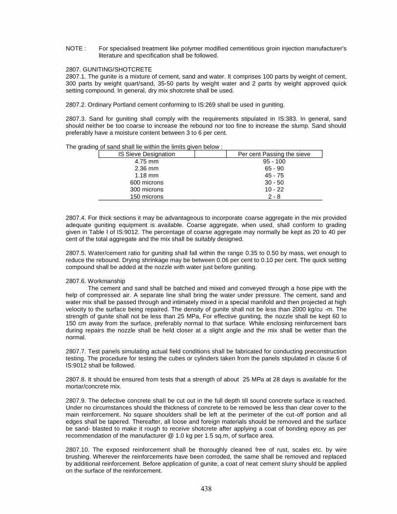
NOTE : For specialised treatment like polymer modified cementitious groin injection manufacturer’sliterature and specification shall be followed.
2807. GUNITING/SHOTCRETE2807.1. The gunite is a mixture of cement, sand and water. It comprises 100 parts by weight of cement,300 parts by weight quart/sand, 35-50 parts by weight water and 2 parts by weight approved quicksetting compound. In general, dry mix shotcrete shall be used.
2807.2. Ordinary Portland cement conforming to IS:269 shall be used in guniting.
2807.3. Sand for guniting shall comply with the requirements stipulated in IS:383. In general, sandshould neither be too coarse to increase the rebound nor too fine to increase the slump. Sand shouldpreferably have a moisture content between 3 to 6 per cent.
The grading of sand shall lie within the limits given below :IS Sieve Designation Per cent Passing the sieve
4.75 mm 95 - 1002.36 mm 65 - 901.18 mm 45 - 75
600 microns 30 - 50300 microns 10 - 22150 microns 2 - 8
2807.4. For thick sections it may be advantageous to incorporate coarse aggregate in the mix providedadequate guniting equipment is available. Coarse aggregate, when used, shall conform to gradinggiven in Table I of IS:9012. The percentage of coarse aggregate may normally be kept as 20 to 40 percent of the total aggregate and the mix shall be suitably designed.
2807.5. Water/cement ratio for guniting shall fall within the range 0.35 to 0.50 by mass, wet enough toreduce the rebound. Drying shrinkage may be between 0.06 per cent to 0.10 per cent. The quick settingcompound shall be added at the nozzle with water just before guniting.
2807.6. WorkmanshipThe cement and sand shall be batched and mixed and conveyed through a hose pipe with the
help of compressed air. A separate line shall bring the water under pressure. The cement, sand andwater mix shall be passed through and intimately mixed in a special manifold and then projected at highvelocity to the surface being repaired. The density of gunite shall not be less than 2000 kg/cu -m. Thestrength of gunite shall not be less than 25 MPa, For effective guniting, the nozzle shall be kept 60 to150 cm away from the surface, preferably normal to that surface. While enclosing reinforcement barsduring repairs the nozzle shall be held closer at a slight angle and the mix shall be wetter than thenormal.
2807.7. Test panels simulating actual field conditions shall be fabricated for conducting preconstructiontesting. The procedure for testing the cubes or cylinders taken from the panels stipulated in clause 6 ofIS:9012 shall be followed.
2807.8. It should be ensured from tests that a strength of about 25 MPa at 28 days is available for themortar/concrete mix.
2807.9. The defective concrete shall be cut out in the full depth till sound concrete surface is reached.Under no circumstances should the thickness of concrete to be removed be less than clear cover to themain reinforcement. No square shoulders shall be left at the perimeter of the cut-off portion and alledges shall be tapered. Thereafter, all loose and foreign materials should be removed and the surfacebe sand- blasted to make it rough to receive shotcrete after applying a coat of bonding epoxy as perrecommendation of the manufacturer @ 1.0 kg per 1.5 sq.m, of surface area.
2807.10. The exposed reinforcement shall be thoroughly cleaned free of rust, scales etc. by wirebrushing. Wherever the reinforcements have been corroded, the same shall be removed and replacedby additional reinforcement. Before application of gunite, a coat of neat cement slurry should be appliedon the surface of the reinforcement.
2807.11. Sufficient clearance shall be provided around the reinforcement to permit encasement withsound gunite. Care shall be taken to avoid sand pockets behind the reinforcement.
2807.12. A thickness of 25 to 40 mm of gunite can normally be deposited in one operation. If, for somereason, the total thickness is to be built up in successive operations, the previous layer should beallowed to set but not become hard before the application of the subsequent layer. It would always benecessary to apply guniting on a damp concrete surface.
2807.13. Where required, welded wire fabrics 5cm x 5 cm X No.10 gauge shall be provided in the firstlayer of guniting. The fabric shall be tied properly. In case die damage to the concrete member is toodeep, the specifications for guniting as well as requirement of placement of wire mesh has to bedecided as per field conditions.
2867.14. The stipulations given in 15:9012 regarding application of gunite should be followed so as tokeep the rebound to the minimum. The quality of guniting and workmanship shall be such that thepercentage of rebound mentioned in IS:9012 can be adhered to. In no circumstances shall the reboundmaterial be re-used in the work.
2807.15. It would be desirable that green gunite is moistened for at least 7 days. Guniting work shall notbe done during windy or rainy conditions.
2808. REPLACEMENT/RECTIFICATION OF BEARINGS2808.1. The replacement/rectification of bearings shall be carried out in accordance with approvedrepair plan or as approved by the Engineer.
2808.2. Lifting of Superstructure spans may be carried out by jacking up from below or by lifting thespan from top. Where jacks are employed, their location/number and size shall be selected in such amanner so that there are no undue stresses created in the structure. Jacks may be placed on piers/piercaps or specially erected trestles in accordance with the approved methodology for lifting ofsuperstructure. All jacks shall be operated from one control panel by a single control lever. The systemwill have provision for manual over ride to control die loads of any particular jack. The jacks should beso synchronised that differential lift between individual jacks shall not exceed 1mm .
2808.3. Necessary repair/replacement of bearings shall be carried out as indicated in the repair plan oras directed by the Engineer. Care shall be taken to plan the execution of repair in the shortest possibleperiod.
2808.4. Precautions during Lifting of Girders for Rectification of Bearings Walkie talkies system orsimilar audio arrangements should be available for communicating instructions regarding lifting,stopping, starting etc. The operator shall have a clear view of the jacks and the lifting of each girdercontrolled by reading the dial gauges.
2809. DISMANTLING OF CONCRETE WEARING COAT2809.1. Commencement of Dismantling
i) Before commencing dismantling, the nature and condition of concrete, the condition andposition of reinforcement should be ascertained. The Contractor shall familiarise himselfwith the structural design and ensure that the overall stability of the bridge is not affected
ii) The existing expansion joint assemblies shall he removed carefully along the entire widthof the carriageway. The deck slab for a width of 400 mm on either side should beremoved for placing of reinforcement, anchor rods, anchor bolls and other fixingassemblies for the new expansion joints and pouring of fresh concrete. The gap betweenthe girders over the piers should be cleared of all debris A temporary platform in the gapat the end of girders shall be erected to collect the materials falling down duringconcreting and fixing of expansion joints.
iii) The service lines, if any, shall be disconnected/ diverted before the dismantling workstarts.
2809.2. Dismantling of concrete wearing coat shall be carried out using jack hammers or suitablemanual methods as approved by the Engineer. Care should be taken to avoid any damage to the
existing structure including reinforcement or prestressing anchorages for cables, if any, located in thedeck slab.
2809.3. Precautions During Dismantling WorkFor general guidelines, reference may be made to Section 100.
Dismantling work shall not be carried out at night, or during storm or heavy rain. A warningdevice shall be installed in the area to be used to warn the workers in case of mishap/emergency.
Safety helmets conforming to IS:2925 shall be used by the workmen engaged in dismantlingwork. The sheds and tool boxes should be located away from the work site. Goggles preferably madeup of celluloids and gas masks shall be worn at the time of dismantling, especially where tools like jackhammers are deployed to protect eyes from injuries from flying pieces, dirt, dust etc. Leather or rubbergloves shall be worn by the workers during the demolition of RCC work. Screens made up of GI sheetsshall be placed wherever necessary to prevent the flying pieces from injuring the workers.
Water should be sprayed to reduce the dust while removing concrete wearing course with jackhammer. No work shall be taken up under the span when dismantling work is in progress.
2810. EXTERNAL PRESTRESSING2810.1. Various components constituting the system of external prestressing are as follows:
H.T. Strands/Wires, HDPE Sheathing, Deviator Blocks, Anchor Plates, Anchorages andgrouting material.
2810.2. MaterialH.T. Strands / Wires :H.T. Strands wires shall conform to Section 1000.HDPE Sheathing :HDPE Sheathing shall conform to IS:4984 suitable for a working pressure of 6 bars. Its density
shall be 955 kg/cum, shore hardness D63, yield stress 24 MPa and ultimate tensile strength 35 MPa.
Deviator Blocks :As necessitated by the profile of the external cable, suitable strand/wire deviator block
fabricated from M.S. Sections shall be provided. The deviator block shall be given a coat of suitablepaint (preferably epoxy based) after sand blasting.
Anchorages :Depending upon the prestressing force, suitable anchorages and wedges shall be used
conforming to relevant codes and section 1800.
28103. Workmanshipa) Stressing of cables shall be carried out as per instructions given in the drawing, and
conforming to Section 1800.b) Care should be taken to avoid any damage to the existing structure by way of stress
concentration or any other reason during fixing of the deviator blocks and after stressingof cable. The deviator blocks shall be so fined as not to allow any movement due toprestressing forces, Radius of curvature of the surface of the deviator block interfacingwith the cable shall be minimum one metre.
c) The anchorages shall be sealed with suitable epoxy mortar system after the stressing ofcables. A minimum cover of 50mm shall be provided for the anchor plates andanchorages.
d) Suitable grouting inlet points and vent points shall be provided by way of HDPE "T" ventconnections to the sheathing.
e) Grouting of cables shall be carried out as per provisions made in Section 1800.
2810.4. It shall be ensured that no part of the existing structure is damaged/distressed due to theexternal prestressing.

The behaviour of the girder shall be monitored by measurement of deflection so that onlyrequired amount of external prestressing is imparted to the girder. Care shall be taken to avoid excessprestressing and impairment to the girders.
2811. TESTS AND STANDARDS OF ACCEPTANCEThe materials shall be tested in accordance with these Specifications and shall meet the
prescribed criteria.
The work shall conform to these Specifications and shall meet the prescribed standards ofacceptance,
2812. MEASUREMENTS FOR PAYMENTa) Measurement for sealing of cracks and injection shall be made by weight of epoxy
consumed in kg for epoxy grouting. For provision of nipples required for grouting, thepayment shall be for number of nipples inserted,
b) Measurement for sealing of cracks and injection shall be made by weight of cementconsumed in kg for cement grouting.
c) Measurement [or application of epoxy mortar for specified thickness shall be per squaremetre of surface area of application.
d) Measurement for bonding of old and new concrete by epoxy mortar shall be measured insquare metre surface area of interface.
e) Measurement for guniting/shotcreting, shall be per square metre of surface area ofapplication.
f) Payment for replacement/rectification of bearings shall be for each number of bearingassembly replaced/rectified.
g) Dismantling of wearing coat shall be measured in square metre of area of wearing coursedismantled.
h) Provision of external presiressing shall be measured in tonnes of H.T. steel strand/wiremeasured from anchorage to anchorage before stressing.
2813. RATEThe contract unit rate for sealing of cracks and injection of cement grout shall include cost of all
materials, labour, tools and plant, placing in position, testing, curing and other incidental expenses forthe satisfactory completion of the work as per these specifications.
The contract unit rate for application of epoxy mortar for specified thickness shall include costof all materials, labour, tools and plant, placing in position, testing and other incidental expensesincluding surface preparation for the satisfactory completion of the work as per these specifications andas shown on the drawings.
The contract unit rate for guniting/shotcreting shall include cost of all materials, labour., toolsand plant, placing in position, testing, curing,- surface preparation and other incidental expensesincluding the provision of nipples for the satisfactory completion of the work as per these specifications.
The contract unit rate for replacement/rectification of bearings shall include cost of ail materials,labour, tools and plant, placing in position, site welding/riveting/bolt connections, operation of jacks andother incidental expenses for the satisfactory completion of the work as per these specifications and asshown on the drawings.
The contract unit rate for dismantling of wearing coat shall include cost of all materials, labour,tools and plant, traffic management, signages, safety precautions and other incidental expensesincluding removal of existing expansion joints for the satisfactory completion of the work as per thesespecifications.
The contract unit rate for external prestressing shall include cost of all materials, labour, toolsand plant, temporary works, testing, curing and other incidental expenses including the carefulmonitoring of the deflection of girders being externally prestressed for the satisfactory completion of thework as per these specifications and as shown on the drawings.

2900 Pipe Culverts
CONTENT
Clause No Description2901 SCOPE
2902 MATERIALS
2903 EXCAVATION FOR PIPE
2904 BEDDING FOR PIPE
2905 LAYING OF PIPE
2906 JOINTING
2907 BACKFILLING
2908 HEADWALLS AND OTHER ANCILLARY WORKS
2909 OPENING TO TRAFFIC
2910 MEASUREMENTS FOR PAYMENT
2911 RATE
2901. SCOPEThis work shall consist of furnishing and installing reinforced cement concrete pipes, of the
type, diameter and length required at the locations shown on the drawings or as ordered by theEngineer and in accordance with the requirements of these Specifications.
2902. MATERIALSAll materials used in the construction of pipe culverts shall conform to the requirements of
Section 1000. Each consignment of cement concrete pipes shall be inspected, tested, if necessary, andapproved by the Engineer either at the place of manufacture or at the site before their incorporation inthe works.
2903. EXCAVATION FOR PIPEThe foundation bed for pipe culverts shall be excavated true to the lines and grades shown on
the drawings or as directed by the Engineer. The pipes shall be placed in shallow excavation of thenatural ground or in open trenches cut in existing embankments, taken down to levels as shown on thedrawings. In case of high embankments where the height of fill is more than three times the externaldiameter of the pipe, the embankment shall first be built to an elevation above the top of the pipe equalto the external diameter of the pipe, and to width on each side of the pipe of not less than five times thediameter of pipe, after which a trench shall be excavated and the pipe shall be laid.
Where trenching is involved, its width on either side of the pipe shall be a minimum of 150 mmor one- fourth of the diameter of the pipe whichever is more and shall not be more than one-third thediameter of the pipe.
The sides of the trench shall be as nearly vertical as possible. The pipe shall be placed wherethe ground for the foundation is reasonably firm. Installation of pipes under existing bridges or culvertsshall be avoided as far as possible. When during excavation the material encountered is soft, spongy orother unstable soil, and unless other special construction methods are called for on the drawings or inspecial provisions, such unsuitable material shall be removed to such depth, width and length asdirected by the Engineer. The excavation shall then be backfilled with approved granular material whichshall be properly shaped and thoroughly compacted upto the specified level. Where bed-rock or boulderstrata are encountered, excavation shall be taken down to atleast 200 mm below the bottom level of thepipe with prior permission of the Engineer and all rock/boulders in this area be removed and the spacefilled with approved earth, free from stone or fragmented material, shaped to the requirements andthoroughly compacted to provide adequate support for the pipe. Trenches shall be kept free from wateruntil the pipes are installed and the joints have hardened.
2904. BEDDING FOR PIPEThe bedding surface shall provide a firm foundation of uniform density throughout the length of
the culvert, shall conform to the specified levels and grade, and shall be of one of the following twotypes as specified on the drawings:
(i) First Class bedding: Under first class bedding, the pipe shall be evenly bedded on acontinuous layer of well compacted approved granular material, shaped concentrically tofit the lower part of the pipe exterior for alleast ten per cent of its overall height or asotherwise shown on the drawings. The bedding material shall be well graded sand oranother granular material passing 5.6 mm sieve suitably com patted/rammed. Thecompacted thickness of the bedding layer shall be as shown on the drawings and in nocase shall it be less than 75 mm.
(ii) Concrete cradle bedding: When indicated on the drawings or directed by the Engineer,the pipe shall be bedded in a cradle constructed of concrete having a mi* not leaner thanM IS conforming no Section 1700, The shape and dimensions of the cradle shall be asindicated on the drawings. The pipes shall be laid on the concrete bedding before theconcrete has set.
2905. LAYING OF PIPENo pipe shall be laid in position until the foundation has been approved by the Engineer. Where
two or more pipes are to be laid adjacent to each other, they shall be separated by a distance equal toat least half the diameter of the pipe subject to a minimum of 450 mm. The arrangement for lifting,loading and unloading concrete pipes from factory/yard and at site shall be such that the pipes do not
suffer any undue structural strain, any damage due to fall or impact. The arrangement may be gotapproved by the Engineer.
Similarly, the arrangement for lowering the pipe in the bed shall be got approved by theEngineer. It may be with tripod-pulley arrangement or simply by manual labour in a manner that thepipe is placed in the proper position without damage.
The laying of pipes on the prepared foundation shall start from the outlet and proceed towardsthe inlet and be completed to the specified lines and grades. In case of use of pipes with bell-mouth, thebelled end shall face upstream. The pipes shall be fitted and matched so that when laid in work, (heyform a culvert with a smooth uniform invert. Any pipe found defective or damaged during laying shall beremoved at the cost of the Contractor.
2906. JOINTINGThe pipes shall be jointed either by collar joint or by flush joint. In the former case, the collars
shall be of RCC 150 to 200 mm wide and having the same strength as the pipes to be jointed. Caulkingspace shall be between 13 and 20 ram according to the diameter of the pipe. Caulking material shall beslightly wet mix of cement and sand in the ratio of 1:2 rammed with caulking irons. Before caulking, thecollar shall be so placed that its centre coincides with the joint and an even annular space is leftbetween the collar and the pipe.
Flush joint may be internal flush joint or external flush joint. In either case, the ends of the pipesshall be specially shaped to form a self centering joint with a jointing space 13 mm wide. The jointingspace shall be filled with cement mortar, 1 cement to 2 sand, mixed sufficiently dry to remain in positionwhen forced with a trowel or rammer. Care shall be taken to fill all voids and excess mortar shall beremoved.
For jointing pipe lines under light hydraulic pressure, the recess at the end of the pipe shall befilled with jute braiding dipped in hot bitumen or other suitable approved compound. Pipes shall be sojointed that the bitumen ring of one pipe shall set into the recess of the next pipe. The ring shall bethoroughly compressed by jacking or by any other suitable method.
All joints shall be made with care so that their interior surface is smooth and consistent with theinterior surface of the pipes. After finishing, the joint shall be kept covered and damp for at least fourdays.
2907. BACKFILLINGTrenches shall be backfilled immediately after the pipes have been laid and the jointing material
has hardened. The backfill soil shall be clean, free from boulders, large roots, excessive amounts ofsods or other vegetable matter, and lumps and shall be approved by the Engineer. Backfilling upto 300mm above the top of the pipe shall be carefully done and the soil thoroughly rammed, tamped orvibrated in layers not exceeding 150 mm, particular care being taken to thoroughly consolidate thematerials under the haunches of the pipe. Approved pneumatic or light mechanical tamping equipmentcan be used.
Filling of the trench shall be carried out simultaneously on both sides of the pipe in such amanner that unequal pressures do not occur. In case of high embankment, after filling the trench uptothe top of the pipe in the above said manner, a loose fill of a depth equal to external diameter of thepipe shall be placed over the pipe before further layers are added and compacted.
2908. HEADWALLS AND OTHER ANCILLARY WORKSHeadwalls, wing walls, aprons and other ancillary works shall be constructed in accordance
with the details shown on the drawings or as directed by the Engineer, Masonry for the walls shallconform to Section 1300,1400 or 1700 as applicable. Aprons shall conform to Section 2500.
2909. OPENING TO TRAFFICNo traffic shall be permitted to cross the pipe line unless height of filling above the top of the
pipe line is atleast 600 mm.
2910. MEASUREMENTS FOR PAYMENT

R.C.C. pipe culverts shall be measured along their centre between the inlet and outlet ends inlinear metres. Selected granular material and cement concrete for pipe bedding shall be measured aslaid in cubic metres. Ancillary works like headways, etc., shall be measured as provided for under therespective Sections.
2911. RATEThe Contract unit rate for the pipes shall include the cost of pipes including loading, unloading,
hauling, handling, storing, laying in position and jointing complete and all incidental costs to completethe work as per these Specifications. Ancillary works such as excavation including backfilling, concreteand masonry shall be paid for separately, as provided under the respective Clauses.

3000 Maintenance of Road

CONTENT
Clause No Description3001 GENERAL
3002 RESTORATION OF RAIN CUTS
3003 MAINTENANCE OF EARTHEN SHOULDER
3004 BITUMINOUS WORK IN CONNECTION WITH MAINTENANCE AND
REPAIRS
3005 MAINTENANCE OF CEMENT CONCRETE ROAD
3001. GENERALThe Specifications shall apply to all items of road maintenance works as required to be carried
out under the Contract or as directed by the Engineer. The works shall be carried out in conformity withthe relevant Specifications to the required level, grade and lines using approved materials. The works’shall be carried out using light duty machinery or manual means provided the quality of the end productdocs not suffer. In execution of maintenance works, a reference is made to the IRC publications:"Manual for Maintenance of Roads" and "Code of Practice for Maintenance for Bituminous Surfaces ofHighways, IRC 82-1982" for guidance and compliance wherever applicable. Wherever the Specificationis not clear, good engineering practice shall be adopted in the construction to the satisfaction of theEngineer,
3002. RESTORATION OF RAIN CUTS3002.1. Scope
The work shall consist of earthwork for restoration of rain cuts in the embankment andshoulders, using suitable material, and compacting the same.
3002.2. MaterialsThe material used for restoration of rain cuts shall consist of soil conforming to Clause 305.2.
3002.3. Construction OperationThe area affected by rain cuts shall be cleared of all loose soil and benched. The width of the
benches shall be at least 300 mm and they shall extend continuously for a sufficient length. The heightof the benches shall be in the range of 150-300 mm.
Fresh material shall be deposited in layers not exceeding 250 mm loose thickness andcompacted so as to match with the benching a: a moisture content close to the optimum. Compactionshall be carried out using suitable equipment such as plate compactors and rammers or by suitableimplements handled manually. The finished work shall conform to alignment, levels and slopes asindicated in the drawing.
3002.4. Measurements for PaymentThe earthwork for restoration of rain cuts shall be measured in cubic metres.
3002.5. RateThe Contract rate for the item of earthwork for restoration of rain cuts shall be payment in full
for carrying out the required operation including full compensation for:(i) Supply of material including alt leads and lifts and the cost of arrangement of land;(ii) Selling out;(iii) Removal of loose material from the rain cuts;(iv) Benching of old earthwork; and(v) Compacting after adding required quantity of water.
3003. MAINTENANCE OF EARTHEN SHOULDER3003.1. Scope
The work of maintenance of earthen shoulder shall include making up the irregularities/loss ofmaterial on shoulder LO the design level by adding fresh approved soil and compacting it withappropriate equipments or to strip excess soil from the shoulder surface as per the requirement of thisSpecification.
3003.2. MaterialThe material to be added lo the shoulder, if required, shall be a select soil conforming to Clause
305.
3003.3. Construction ProcedureThis work shall involve:(i) Making up of the earthen shoulder by adding extra soil and compacting the same; and/or(ii) Stripping a foyer of soil to achieve the required grade and level.
Wherever extra earth is required to be added, the earthen shoulder shall be stripped andloosened to receive fresh soil. The deficiency of thickness shall be made up in layers of loose thicknessnot exceeding 250 mm. Water shall be added, if required, to attain the optimum amount and the layer
compacted by 80 to 100 kN smooth wheel roller, vibratory roller, hand roller, plate vibrator or handrammer to obtain atleast 94 per cent of the maximum dry density in accordance with IS : 2720 (Part 8).The finished surface shall have the specified cross slope and line in accordance with the drawing. Theside slopes shall be trimmed to the required slope with the help of grader or manual methods usinghand tools.
Wherever the earth is required to be excavated from the shoulder, this shall be done eitherusing equipment like grader or by manual means using hand tools. The resulting surface shall beuniform and have a field density of atleast 94 per cent of maximum density obtained in accordance withIS : 2720 (Pan 8). 5f the surface is not uniformly compacted, it shall be excavated to a depth of 150 mmand the soil mixed with water if required and compacted at a moisture content close to the optimum toachieve 94 per cent of maximum density as stated above.
3003.4. Measurements for PaymentMaintenance of earthen shoulder shall be measured in sq. metres.
3003.5. RateThe Contract unit rate for maintenance of earthen shoulder shall be payment in full
compensation for:(i) furnishing earth required for making up of shoulders including all leads and lifts, cost of
land and compaction;(ii) excavation of earth as required and disposal of the earth at the location approved; and(iii) all tools, equipments and incidentals to complete the work in accordance with the above
Specification.
3004. BITUMINOUS WORK IN CONNECTION WITH MAINTENANCE AND REPAIRS3004.1. Filling Pot-holes and Patch Repairs3004.1.1. Scope : This work shall include repair of pot-holes and patching of all types of bituminoussurfaces with a bituminous mix either produced at plant site or at the site itself with manual method ofmixing and placed at site in the pot holes or in patches after trimming the pot-hole or depression toproper shape and depth, side painting with tack coat and compacting the layer to the levels specified inthe drawing.
3004.1.2. Materials : The materials used for the pot-hole and patch repair of bituminous surface shall beas per the Contract and shall be of the same type as used for the existing bituminous surface, A mixsuperior to the one on existing surface can also be considered appropriate for repair work.
An emulsified bitumen mix compatible with the existing layer shall also be consideredappropriate.
The grading of aggregates and bitumen content of the mix used for such patch repair shall bein accordance with Clause 501.
3004.1.3. Preparation of the area for pot-hole and patch repair: Each pot-hole and patch repair areashall be inspected and all loose material removed. The area shall be cut/trimmed either with jackhammer or hand tools like chisels, pick-axes etc., such that the area is in the shape of a rectangle orsquare. The edges shall be cut vertically upto the level where the lower layer is stable without any loosematerial. The area shall be thoroughly cleaned with compressed air or any appropriate methodapproved by the Engineer to remove all dust and loose particles. The area shall be tacked or primedwith cutback or emulsion depending upon whether the lower layer is bituminous or granular in nature.The sides, however, are to be painted with hoi lack coat material using a brush. The prime coat andtack coat shall conform to Clauses 502 and 503 of these Specifications, respectively.
3004.1.4. Backfilling operation : The mix to be filled shall be either a hot mix or a cold storable mix_(using bituminous emulsion). Mixing shall be done in a plant of suitable capacity. It shall be placed inthicknesses not more than 100 mm (loose). H shall be compacted in layers with roller/platecompactor/hand roller/ rammer. While placing the final layer, the mix shall be spread slightly proud ofthe surface so that after rolling, the surface shall be flush with the adjoining surface. If the area is large,the spreading and levelling shall be done using hand shovel and wooden straight edge. During theprocess of compaction with roller or other means, the surface level shall be checked using a 3 mstraightedge.
3004.1.5. Measurements for payment: Filling of pot-holes and patch repair shall be measured in sq.m.
3004.1.6. Rate: The Contract unit rate for filling of poi -holes and patch repair shall be in fullcompensation for:
(i) furnishing all materials required;(ii) works involved in trimming, tacking, palming with cutback or emulsion;(iii) all labour, tools, equipments and incidentals to complete !he work in accordance with the
Specifications.
3004.2. Sealing of Cracks with Fog Seal3004.2.1. Scope : Fog seal shall consist of an application of emulsified bitumen, without any aggregatecover for sealing fine hair-cracks like shrinkage cracks and alligator cracks or rejuvenating oxidisedbituminous surfaces. Areas having cracks with less than 3 mm width shall be considered for thistreatment.
3004.2.2. Material: Bituminous emulsion for Fog Seal shall be of a slow setting type.
3004.2.3. Application : The area to be applied with fog seal shall be thoroughly cleaned withcompressed air, scrubbers, etc. The cracks shall be cleaned with pressure air jet to remove all dirt,dust, etc. The fog seal shall be applied at the rate of 0.5-1.0 litre/sq.m, using equipment like a pressuretank, flexible hose and spraying bar or lance. Traffic shall be allowed on the surface after the seal hasset to a non -tacky and firm condition so that it is not picked up by the traffic.
3004.2.4. Measurements for payment: The fog seal work shall be measured in sq. metres.
3004.2.5. Rate : The Contract unit rate for application of fog seal shall be in full compensation for:(i) supplying of fog seal material and all the operations for applying ii: and(ii) all the labour, tools, equipments and incidentals lo complete the work in accordance with
this Specification.
3004.3. Slurry SealsClause 516 shall apply, with the modification that simple implements and tools amenable to
manual methods shaft be used.
3004.4. Premix Carpet for Renewal of SurfaceThe work shall consist of laying a 20 mm thick open-graded premix carpel for renewal of
surface. The stipulations contained in Clause 509 shall govern as regards scope and materials. A tackcoat shall be applied conforming to Clause 503, but manual methods or use of relatively small capacityequipment shall be permitted. The premix shall be prepared in hot-mix plants of suitable capacity orsmall portable mixers, approved by the Engineer. Rolling shall be done as per Clause 509.1.3.5. A sealcoat conforming to Clause 513 shall be applied after laying the carpet.
The work shall be measured in sq. metres and the Contract unit rate shall cover supply of allmaterials, labour and equipment and carrying out the work to Specifications.
3004.5. Surface Dressing for Maintenance WorkThe work shall be done in conformity with Clause 508, except that the use of small and portable
equipment shall be permitted.
3005. MAINTENANCE OF CEMENT CONCRETE ROAD3005.1. Repair of Joint Grooves with Epoxy Mortar or Epoxy Concrete3005.1.1. Scope: The work shall consist of repair of spalled joint grooves of contraction joints,longitudinal joints and expansion joints in a concrete pavement using epoxy mortar or epoxy concrete.
3005.1.2. Materials: The type/grade of epoxy compatible with the coefficient of thermal expansion ofconcrete shall be used with either processed fine aggregate or fine stone chips to produce a dry m ix forrepairing spalled or damaged edges.
3005.1.3. Repairing Procedure: Spalled or broken edges shall be shaped neaily with a vertical cut withchisels into the shape of rectangle. Small pneumatic chisels also may be used, provided the cutting

depth can be controlled. The depth of the cut shall be the minimum to effect repair, After shaping thespalled area, it shall be cleaned and primed. The epoxy mortar/concrete is then applied using handtools like trowels, straightedges, brushes etc. The repair edge shall be in line with the joint groove andshall be flush with the concrete slabs. During the repair work, any damage noticed to the joint sealantshall be made good by raking out the affected portion and resealing.
3005.1.4. Traffic: Although the epoxy mixes set in 2-3 hours time, it is desirable to divert the traffic for12 hours or as per the recommendation if the manufacturers.
3005.1.5. Measurements for payment: Repair of joint grooves shall be measured in linear metres.
3005.1.6. Rate : The Contract unit rate for repair of joint grooves with epoxy mortar or epoxy concreteshall be in full compensation for:
(i) supply and application of epoxy primer, epoxy mortar or epoxy concrete;(ii) all tools, equipment and incidentals to complete the work in accordance with the above
Specification.
3005.2. Repair Involving Removal of Old Joint Sealant and Sealing with Fresh Sealant in CementConcrete Pavements.
3005.2.1. Scope: The repair of sealant of contraction, longitudinal or expansion joints shall includeremoval of the existing sealant and resealing the joint with fresh sealant material.
3005.2.2. Material: Sealant material to be replaced shall be either hot poured rubberised bitumen orpolysulphide type of sealant as per Clause 602.2.8, As per the recommendation of the manufacturer,appropriate type of primer also shall be applied.
3005.2.3. Repairing procedure: The existing sealant shall he raked out with the help of a metal rakersuch that most of the sealant is removed. Subsequently, the sealant stuck to the sides of the groovesshall be removed thoroughly either by using saw cutting machine so that grooves may be widened byone mm or by sand blasting. In no case the old sealant shall be present during reseating operation. Ifjoint grooves are found inadequate in depth, they shall be deepened as directed by the Engineer.
Before commencing the sealing operation, compressed air shall be used 10 clean the jointgrooves to clean the joint groove. A heat resistant, papers backed compressible debonding strip ortape should be inserted in accordance with the requirement of Clause 602.11.2. Sealant may be pouredcither using hand held poorer or using mechanised sealing machines.
Sealants should not be heated directly but in double jacketed machine. All precautions andarrangements shall be taken not to spill the sealant on the concrete pavement. The sealant may bepoured to a depth of 5 ± 2 mm from the pavement surface.
3005.2.4. Measurements for payment: Repair of joint sealant shall be measured in linear metres.
3005.2.5. Rate: Contract unit rate for repair of joint sealant shall be in full compensation for:(i) removal of old Sealant, regrooving or sand blasting the sealing groove and placing of
debonding strip or tape.(ii) all tools, equipments and incidentals to complete the work in accordance with the above
Specification.