part 2 — systems other than - airah€¦ · 9 cleaning and flushing ... australia and new zealand...
TRANSCRIPT

Part 2 —
Systems other than self-contained low
charge systems
Prepared by the Australian Institute of Refrigeration, Air Conditioning and Heating (AIRAH)
and the Institute of Refrigeration, Heating and Air Conditioning Engineers New Zealand (IRHACE)
Australia and New Zealand
Refrigerant handling code of practice 2007


Australia and New Zealand refrigerant handling code of practice 2007
Part 2 –
Systems other thanself-contained low
charge systems
Prepared by the Australian Institute of Refrigeration, Air Conditioning and Heating (AIRAH) and the Institute of Refrigeration, Heating and Air Conditioning Engineers New Zealand (IRHACE)
With funding from the Australian Government Department of the Environment and Water Resources and the New Zealand Climate Change Office
Date of publication: September 2007

Australia and New Zealand refrigerant handling code of practice 2007 • Part 2 — Systems other than self-contained low charge systems2
I Acknowledgements ____________________________________________________________________________________________________ 4
II Scope ________________________________________________________________________________________________________________________ 5
III Referenced documents _______________________________________________________________________________________________ 5
IV Acronyms for standards and organisations and relevant websites ______________________________ 6
V Definitions _______________________________________________________________________________________________________ 6
VI How to read this code _________________________________________________________________________________________________ 8
1 General _______________________________________________________________________________________________________________________ 9
1.1 Personnel __________________________________________________________________________________________________________ 9
1.2 Refrigerant venting _____________________________________________________________________________________________ 9
2 Design _______________________________________________________________________________________________________________________10
2.1 Design of mass-manufactured systems ________________________________________________________________10
2.2 General ____________________________________________________________________________________________________________10
2.3 Compressors _____________________________________________________________________________________________________ 11
2.4 Refrigerant condensers and evaporators ______________________________________________________________12
2.5 Refrigerant pipelines and fittings _________________________________________________________________________13
2.6 Valves ______________________________________________________________________________________________________________13
2.7 Relief device ____________________________________________________________________________________________________ 14
2.8 Air purgers (negative pressure systems) _______________________________________________________________ 15
2.9 Pump down capability ______________________________________________________________________________________ 15
2.10 Charge monitors and leak detectors ___________________________________________________________________ 16
3 Manufacture and assembly _______________________________________________________________________________________ 16
3.1 General ___________________________________________________________________________________________________________ 16
3.2 Leak testing _____________________________________________________________________________________________________ 16
3.3 Charging of refrigerant _______________________________________________________________________________________ 17
4 Provision of information on installation, use and maintenance __________________________________ 17
5 Installation procedures ______________________________________________________________________________________________ 17
6 Evacuation ________________________________________________________________________________________________________________ 20
Table of contents

3Australia and New Zealand refrigerant handling code of practice 2007 • Part 2 — Systems other than self-contained low charge systems
7 Commissioning _________________________________________________________________________________________________________ 21
8 Servicing of equipment _____________________________________________________________________________________________ 22
9 Cleaning and flushing _______________________________________________________________________________________________ 24
10 Labelling ___________________________________________________________________________________________________________________ 25
11 Maintenance _____________________________________________________________________________________________________________ 26
11.1 General maintenance ________________________________________________________________________________________ 26
11.2 Advice to equipment users ________________________________________________________________________________ 27
12 Retrofitting _______________________________________________________________________________________________________________ 28
13 Decommissioning _____________________________________________________________________________________________________ 28
14 Recovery, recycling and disposal of refrigerants ________________________________________________________ 28
14.1 During manufacture, installation and servicing_____________________________________________________ 28
14.2 Disposal of refrigerants ______________________________________________________________________________________ 30
15 Handling and storage of refrigerants ________________________________________________________________________ 31
15.1 Handling and storage _______________________________________________________________________________________ 31
15.2 Charging _________________________________________________________________________________________________________ 32
15.3 Refrigerant transfer between cylinders ________________________________________________________________ 32
16 Appendices _______________________________________________________________________________________________________________ 33
16.1 Appendix 1 — dealing with the recovery of fluorocarbons mixed
with other refrigerants _______________________________________________________________________________________ 33
16.2 Appendix 2 — fluorocarbon refrigerants _____________________________________________________________33
16.3 Appendix 3 — safety group classifications __________________________________________________________ 37

Australia and New Zealand refrigerant handling code of practice 2007 • Part 2 — Systems other than self-contained low charge systems4
I AcknowledgementsThis Code of Practice was developed with assistance from a review committee and was subject to public comment prior to publication. AIRAH wishes to acknowledge the committee members who have contributed to the preparation of the document, including:
Bruce Buchtmann — Electrolux Home Products Pty Ltd
Ray Clarke — ISECO Consulting Services Pty Ltd
Don Cleland — Massey University, New Zealand
Rachael Clarke — Department of the Environment and Water Resources (Australia)
Craig Duff — Active Refrigeration Ltd
Greg Groppenbacher — Air Conditioning and Refrigeration Equipment Manufacturers Association (Australia)
Scott Miller — A-Gas Australia Pty Ltd
Lindsey Roke — Fisher and Paykel Appliances Ltd
David Smalldon — TAFE Australia
Steve Spurling — A-Gas Australia Pty Ltd
Ben Stapley — Department of the Environment and Water Resources (Australia)
Christopher Young — Department of the Environment and Water Resources (Australia)
Editing and drafting by Stuart West and Bonnie Alexander (Australian Institute of Refrigeration, Air Conditioning and Heating).
© Commonwealth of Australia 2007
ISBN 978 0 642 55379 3
Information contained in this publication may be copied or reproduced for study, research, information or educational purposes, subject to inclusion of an acknowledgment of the source.
The views and opinions expressed in this publication are those of the authors and do not necessarily reflect those of the Australian Government or the Minister for the Environment and Heritage. Neither has this publication been endorsed by the New Zealand Government including the Ministry for the Environment.
While reasonable efforts have been made to ensure that the contents of this publication are factually correct, the Commonwealth does not accept responsibility for the accuracy or completeness of the contents, and shall not be liable for any loss or damage that may be occasioned directly or indirectly through the use of, or reliance on, the contents of this publication.

5Australia and New Zealand refrigerant handling code of practice 2007 • Part 2 — Systems other than self-contained low charge systems
II Scope This code applies to all refrigeration and air conditioning systems which use fluorocarbon refrigerants, including heat pumps and transport refrigeration and air conditioning systems, but excluding:
• Appliances which contain a fluorocarbon refrigerant charge of two kilograms or less, and do not require any work to be done on the refrigeration system at the time of installation (such systems are covered by the Australia and New Zealand refrigerant handling code of practice 2007 Part 1 – self contained low charge systems)
This code has been developed with the intention of reducing emissions into the atmosphere of refrigerants listed in Appendix 2, or any other fluorocarbon refrigerant. This code specifies requirements which are mandatory for compliance with the code, and also includes best practice recommendations. Environmental benefits and cost savings from reduced losses can be expected from the application of this code including the use of alternative refrigerants.
Systems which do not use a fluorocarbon refrigerant (or do not use a refrigerant blend containing a fluorocarbon) are not covered by this code.
III Referenced DocumentsThe following documents are referred to in this code:
Document Title
AIRAH DA19 HVAC&R Maintenance
AS/NZS 1200:2000 Pressure Equipment
1571:1995 Copper - Seamless tubes for air conditioning and refrigeration
1677.2:1998 Refrigerating systems. Part 2: Safety Requirements for fixed applications
3823.1.1:1998 Performance of electrical appliances – air conditioners and heat pumps – test methods – non-ducted air conditioners and heat pumps – testing and rating for performance
AS 1210:1997 Pressure Vessels
3823.1.2:2001 Performance of electrical appliances – Air conditioners and heat pumps - Test methods - Ducted air conditioners and air-to-air heat pumps - Testing and rating for performance
2030.1:1999 The verification, filling, inspection, testing and maintenance of cylinders for storage and transport of compressed gases – Cylinders for compressed gases other than acetylene
4041:1998 Pressure Piping
4211.3:1996 Gas recovery on combined recovery and recycling equipment. Part 3: Fluorocarbon refrigerants from commercial/domestic refrigeration and air conditioning systems
4484:2004 Gas cylinders for industrial, scientific, medical and refrigerant use – Labelling and colour coding
ANSI/ARI 580-2001 Non-Condensable Gas Purge Equipment for Use with Low Pressure Centrifugal Liquid Chillers
ARI 700-2004 Specification for Fluorocarbon Refrigerants
ASHRAE Guideline 1-1996 The HVAC Commissioning Process
Code M Commissioning - Management

Australia and New Zealand refrigerant handling code of practice 2007 • Part 2 — Systems other than self-contained low charge systems6
Australian Act Ozone Protection and Synthetic Greenhouse Gas Management Act 1989 (as amended in 2003)
Australian Regulation Ozone Protection and Synthetic Greenhouse Gas Management Regulations 1995
Australia / New Zealand Code of Practice
Australia and New Zealand refrigerant handling code of practice Part 2 – systems other than self-contained low charge systems
CIBSE Code C Commissioning – Controls
New Zealand Act Ozone Layer Protection Act 1996
SAE J51 Refrigerant 12 Automotive Air Conditioning Hose
Acronym Standard/Organisation Website
AIRAH Australian Institute of Refrigeration Air Conditioning and Heating
www.airah.org.au
ANSI American National Standards Institute www.ansi.org
ARC Australian Refrigeration Council www.arctick.org
ARI Air-Conditioning and Refrigeration Institute (American) www.ari.org
AS Australian Standard www.standards.org.au
DEW Department of Environment and Water Resources (Australia)
www.environment.gov.au
IRHACE Institute of Refrigeration, Heating and Air Conditioning Engineers New Zealand
www.irhace.org.nz
NZCCO New Zealand Climate Change Office www.mfe.govt.nz
NZS New Zealand Standard www.standards.co.nz
RRA Refrigerant Reclaim Australia www.refrigerantreclaim.com.au
SAE Society of Automotive Engineers (American) www.sae.org
V DefinitionsFor the purp ose of this code the following definitions apply:
Alternative refrigerant Alternative refrigerant means a refrigerant other than that for which a system was designed.
Blend A combination of two or more refrigerants in a defined ratio which forms a refrigerant with specified thermodynamic properties.
Compatible Components are compatible when they can be operated together without degrading the overall performance of the system.
IV Acronyms for Standards and Organisations and Relevant Websites

7Australia and New Zealand refrigerant handling code of practice 2007 • Part 2 — Systems other than self-contained low charge systems
Contaminated refrigerant A refrigerant containing oil, acid, non-condensable substances and/or moisture and/or other foreign substances. This could include mixed refrigerants (cocktails) which are not a manufactured product.
Cylinder A portable storage vessel designed for the safe storage and handling of refrigerant gases under pressure.
Decommissioning The process whereby a system is deliberately rendered inoperable.
Destruction A process whereby a refrigerant is permanently transformed or decomposed into other substances.
Disposable container, disposable refrigerant container A non-refillable cylinder.
Factory matched Systems that require interconnecting pipe work and electrical connections between the separate evaporator unit and the condensing unit, where the evaporator and condenser unit have been matched by the manufacturer.
Fluorocarbon A hydrocarbon in which some or all of the hydrogen atoms have been replaced by fluorine.
Fluorocarbon refrigerant A refrigerant consisting of or containing fluorocarbon.
Global warming potential (GWP) The atmospheric warming impact of a gas compared with an equal mass of carbon dioxide over a specified period of time (usually 100 years).
Heat pump A refrigerating system where the main purpose is to make use of the heat rejected by the system, for example to provide space, process or water heating.
Major components and sub assemblies Equipment including compressors, air/water cooled condensers, liquid receivers, chilled water heat exchangers, evaporators and air/water cooled condensing units.
Must When used for a provision, indicates that the provision is mandatory for compliance with this code.
Negative pressure systems Systems in which the pressure may fall below atmospheric under normal operating conditions.
Ozone depletion potential (ODP) The capacity of a refrigerant to destroy stratospheric ozone. ODP is stated relative to the ODP of CFC-11, which is taken as having an ODP of 1.
Plant A combination of one or more refrigerating systems at a single site.
Reclaim To reprocess used refrigerant to new product specification by means which may include distillation. Chemical analysis of the refrigerant is required to determine that appropriate product specifications have been met. This term usually implies the use of processes or procedures available only at a specialised reclaim or manufacturing facility.

Australia and New Zealand refrigerant handling code of practice 2007 • Part 2 — Systems other than self-contained low charge systems8
Recover, recovery To remove refrigerant in any condition from a system and store it in an external cylinder, without necessarily testing or processing it in any way.
Refrigerant The medium used for heat transfer in a refrigerating system, which absorbs heat on evaporating at a low temperature and a low pressure and rejects heat on condensing at a higher temperature and higher pressure. (The term ‘gas’ should be avoided when referring to refrigerants). Unless specified otherwise, ‘refrigerant’ in this code refers to fluorocarbon refrigerant only.
Refrigerating system An assembly of piping, vessels, and other components in a closed circuit in which a refrigerant is circulated for the purpose of transferring heat.
Retrofit To replace the original refrigerant (and components, lubricant, etc as required) in a system with an alternative.
Returned refrigerant Refrigerant recovered from a system and returned to the supplier or equivalent for reclaim or destruction.
Self-contained low charge systems Appliances which contain a fluorocarbon refrigerant charge of two kilograms or less, and do not require any work to be done on the refrigeration system at the time of installation.
Should, recommended Indicate provisions which are not mandatory for compliance with this code but which are desirable as best practice.
Transport refrigeration Any mobile refrigeration system other than air conditioning systems for passenger vehicles.
For definitions of other components, refer to AS/NZS 1677.2-1998 section 1.4: Definitions.
VI How to read this codeText in the remainder of this document is colour coded for ease of use.
Text with a blue background, and containing the term ‘must’ in bold font, indicates compliance is mandatory.
Sections with a green background, and containing the terms ‘should’ or ‘recommended’ are not mandatory but are recommended as best practice.
Sections with plain background are explanatory notes, and are for informative purposes only.
Note for Australian users:
The use of fluorocarbon refrigerants in Australia is governed by the Ozone Protection and Synthetic Greenhouse Gas Management Act 1989 (as amended in 2003) and the Ozone Protection and Synthetic Greenhouse Gas Management Regulations 1995.
Any provisions contained in the Australian regulations take precedence over provisions in this code. The provisions in this code, however, take precedence over any original equipment manufacturer instructions (except where specified otherwise herein).

9Australia and New Zealand refrigerant handling code of practice 2007 • Part 2 — Systems other than self-contained low charge systems
1 General1.1 Personnel
1.1.1 In Australia, any person whose business includes the manufacturing, installation, servicing, modifying, or dismantling of any refrigeration and/or air conditioning equipment which:
(a) contains
(b) is designed to use, or
(c) is manufactured using
any fluorocarbon refrigerant, must ensure that they and/or any of their employees who handle fluorocarbon refrigerant are appropriately licensed under the Ozone Protection and Synthetic Greenhouse Gas Management Act and any regulations that supersede it.
For further details on the Australian licensing system, see www.environment.gov.au or www.arctick.org
1.1.2 In New Zealand, any person whose business is or includes the manufacturing, installation, servicing, modifying, or dismantling of any refrigeration and/or air conditioning equipment which:
(a) contains
(b) is designed to use, or
(c) is manufactured using
any fluorocarbon refrigerant, must ensure that they and/or any of their employees who handle fluorocarbon refrigerant possess a ‘No-Loss’ card.
The No-Loss card is a card indicating the completion of a voluntary training program run by the New Zealand government and the Institute of Refrigeration, Heating and Air Conditioning Engineers New Zealand (IRHACE). For more details see www.irhace.org.nz.
1.1.3 Any person whose business is or includes the manufacturing, installation, servicing, modifying, or dismantling of any refrigeration and/or air conditioning equipment which:
(a) contains
(b) is designed to use, or
(c) is manufactured using
a fluorocarbon refrigerant, must ensure that they and/or any of their employees who handle fluorocarbon refrigerant are provided with a copy of this code and work to the standards set out herein.
1.2 Refrigerant venting
1.2.1 Fluorocarbon refrigerant must not be willingly released to the atmosphere by any person by any means where the release is avoidable, including:
(a) venting refrigerant directly, and
(b) charging refrigerant into equipment with identified leaks.

Australia and New Zealand refrigerant handling code of practice 2007 • Part 2 — Systems other than self-contained low charge systems10
2 Design
This section deals with the design considerations of new air conditioning and refrigeration systems and components and alterations to existing systems. It also identifies possible sources of inadvertent loss of refrigerants to the atmosphere
2.1 Design of mass-manufactured systems
2.1.1 All systems must be designed so that they are able to be:
(a) manufactured,
(b) installed,
(c) operated,
(b) serviced, and
(c) decommissioned
without the avoidable loss of refrigerant as described in 1.2.1.
2.1.2 Where the designer can provide evidence that a system has been designed to an equivalent or better standard than is set out in this section, and complies with clause 2.1.1, the design will be exempt from sections 2.2 to 2.10 inclusive.
Where this can not be demonstrated, the system design must comply with sections 2.2 to 2.10 in their entirety.
2.2 GeneralGood system design is necessary for the prevention of refrigerant leakage.
2.2.1 All systems must be designed in accordance with the applicable Australian and New Zealand standards.
2.2.2 Pipework must have sufficient flexibility to accept structural movement during earthquakes, in accordance with AS 4041:1998, section 1: Scope and general.
2.2.3 For transport refrigeration systems, vibration absorbing mountings, flexible refrigerant hosing and/or vibration eliminators must be incorporated into the system design as appropriate to minimise the effect of vibration.
Refer to section 1 of AS 4041:1998 to determine class of piping and requirements. Fluorocarbon systems are generally class 3, with limited requirements for design installation and testing.
2.2.4 The fixings of plant, pipework and fittings should be designed to resist wind, seismic vibration and other loads that may be imposed on them during their life.
2.2.5 Refrigerating systems should be designed to minimise the amount of refrigerant required.

11Australia and New Zealand refrigerant handling code of practice 2007 • Part 2 — Systems other than self-contained low charge systems
2.3 CompressorsLeaks associated with compressors can generally be attributed to either the ancillary equipment attached to the compressor, (gauge and control connections, oil return, oil drain, oil sight glass, service valves, relief valve and connecting pipe work) or, in the case of open drive compressors the shaft seal. Proper initial installation, combined with a correct ongoing maintenance program, should minimise if not eliminate these problems (see also 11.1).
If contaminated oil reaches the seal it can cause damage to the shaft and seal. Oil can become contaminated in many ways, the most common being foreign matter such as minute copper particles or other metal dust mixing with the oil. Moisture also creates problems. Excess moisture in the system can combine with the refrigerant to form an acid solution leading to oil breakdown, component corrosion, and the formation of sludge. Therefore a clean dry system is essential for prolonged shaft seal effectiveness.
2.3.1 The shaft seal must be compatible with the compressor, oil and refrigerant used in the system.
2.3.2 The shaft seal must be capable of containing any pressure or vacuum that may be attained during both operational and any shut down periods.
2.3.3 Technicians must ensure manufacturers’ specifications are always complied with, especially when changing refrigerants and lubricants.
2.3.4 All lubricants used must be compatible with the refrigerant and equipment used, as indicated by the refrigerant/equipment manufacturer’s specifications.
2.3.5 Refrigerant dryers must be compatible with the refrigerant and lubricant used in the system.
2.3.6 Provisions for removing moisture and solids, and oil filtration, must be made to ensure the necessary level of cleanliness is maintained.
2.3.7 The compressor must be mounted on a solid foundation and/or anti-vibration mountings to avoid leaks caused by vibration, as recommended by the compressor manufacturer.
2.3.8 Isolation valves must be installed where gauges are fitted to minimise the chance of refrigerant loss during servicing or replacement, in accordance with AS/NZS 1677.2:1998, clause 3.6.9.3: Isolating Valves.
2.3.9 Isolation/evacuation valves must be fitted to systems to assist in the servicing and maintenance of plant (see also 2.3.10 to 2.3.13 inclusive, 2.6.5 and 2.9.8).
2.3.10 Service valves should be fitted to both the suction and delivery sides of the compressor to minimise refrigerant discharge during service work, in all systems except those which are hermetically sealed (see 2.3.13 and also 2.6).
2.3.11 Pump out capability within a system with isolating valves must be provided for system servicing where compressor service valves are not installed.
2.3.12 Service access ports must be provided on all transport refrigeration systems to allow refrigerant removal and charging.
2.3.13 Transport refrigeration systems must have service valves located at the compressor and other locations (in accordance with AS/NZS 1677.2:1998).
2.3.14 Superior shaft seals that do not rely on carbon faces should be used to prevent leakage of refrigerant. The provision of double shaft seals is advantageous.

Australia and New Zealand refrigerant handling code of practice 2007 • Part 2 — Systems other than self-contained low charge systems12
Lack of lubrication can cause seal mating surfaces to dry out and adhere. Subsequently, dry starting can cause damage to the seal faces. To avoid this in large systems it is necessary to have a separate oil pump to lubricate the compressor bearings and shaft prior to start-up.
2.3.15 Inclusion of a gas muffler or equivalent to reduce gas pulsation is recommended, especially on large capacity systems. Eliminating vibration in the suction and delivery lines connected to the compressor will also minimise the potential for leaks.
2.3.16 Pipeline connections to the compressor must be supported in accordance with AS 4041:1998, section 3: Design to avoid unacceptable stresses which could lead to leakage or fracture (see also 2.5.6).
2.3.17 Multiple compressors should be fitted with independent isolation valves where practical.
2.3.18 Oil equalising lines between compressors should be fitted with isolation valves which allow for the removal of individual compressors without the loss of refrigerant.
2.3.19 Replaceable dryers should be used on all systems, however, replaceable core dryers should be used on larger systems.
2.4 Refrigerant condensers and evaporators
Properly designed and manufactured condensers and evaporators have few leakage problems, however, the following points need to be considered and appropriate action taken.
2.4.1 All systems must be designed with materials selected to minimise the risk of corrosion.
2.4.2 The system must be designed to avoid excessive fluid velocity through the heat exchangers which can cause vibration and erosion failures.
2.4.3 Fluid velocity must not exceed the maximum safe working velocity of any material used.
2.4.4 Sacrificial anodes, cathodic protection systems or another anti-corrosion measure must be provided where it is necessary to reduce corrosion and protect against electrolytic action.
2.4.5 Anti-vibration mountings and mufflers are highly recommended, as excessive vibration from compressors or other equipment can cause heat exchanger tubing failure (see also 2.3.7).
2.4.6 Where cooling water quality is poor, for example with sea water or bore water, treatment and filtration methods should be designed to avoid corrosion or erosion failure.
2.4.7 The tube plate and tube materials appropriate to the type of water must be selected to minimise corrosion in the case of 2.4.6.
2.4.8 Facilities for flushing and/or drainage must be fitted since reduced or inactive water-flow may lead to serious corrosion problems, especially on sea water cooled systems.

13Australia and New Zealand refrigerant handling code of practice 2007 • Part 2 — Systems other than self-contained low charge systems
2.5 Refrigerant pipelines & fittings
2.5.1 All pipelines must be designed so that the number of joints is kept to the practical minimum.
2.5.2 Welding, brazing or another permanent hermetic sealing method is recommended for joining refrigerant pipelines since they offer increased resistance to pressure, temperature and vibration stresses.
2.5.3 Flared, screwed or flanged connections should be avoided.
2.5.4 Where flanged joints are used, attention must be given to the selection of gaskets, joining materials and joint design to withstand the pressures and temperatures involved and the effects of exposure to the refrigerant/oil mixtures.
2.5.5 Pipelines must be welded or brazed to flanges wherever possible.
2.5.6 Pipelines must be designed to minimise breakage due to vibration.
2.5.7 Lines to fitted gauges, high pressure and low pressure cut outs and oil safety switches, etc., must be designed to minimise breakage due to vibration.
2.5.8 Provision must be made for thermal movements in the pipework, and loops/anchors incorporated.
2.5.9 Strainers, filters, and dryers sized for the system must be included to ensure all the refrigerant and oil circulated throughout the system stays clean and moisture free.
2.5.10 Liquid line solenoids fitted for the purpose of system control should be sited as close to the evaporator as practical to reduce the effect of liquid hammer.
2.5.11 Trombone bends or spring hangers should be used for large pipelines (75mm diameter or above).
2.5.12 Care should be taken where vibration loops are created on small lines to prevent pipes rubbing through, and to support the weight and forces developed in the vibration loop.
2.5.13 A moisture indicating liquid line sight glass installed with the dryer is strongly recommended.
2.5.14 Full flow filter dryers should be used in preference to bypass dryers .
2.5.15 Refrigerant flexible hose should comply with SAE Standard J51.
2.5.16 Flexible hose connections should incorporate `O’ ring seals or flared fittings to ensure minimum leakage of refrigerants.
2.6 Valves
2.6.1 Where valves with removable packing are used they must have retained or captive spindles and facilities for tightening or replacement of the gland packing under line pressure.
2.6.2 The system must be designed to enable valves which use packing to retain leakage from the spindle gland and to remain capped at all times unless being opened or closed. For example; expansion valves, service valves and packed line valves.
2.6.3 Valves with welded or brazed connections must be used where the valve size exceeds 18mm outside diameter.

Australia and New Zealand refrigerant handling code of practice 2007 • Part 2 — Systems other than self-contained low charge systems14
2.6.4 Preference should be given to valves with welded or brazed connections in all
instances (see also 2.5.2).
2.6.5 Isolation and service valves must be included in the system (excluding transport refrigeration systems) to enable the pump down and isolation of major components and equipment.
2.7 Relief device
This section should be read in conjunction with AS/NZS 1677.2:1998.
2.7.1 Systems must have relief devices selected for the refrigerant and operating conditions of the system.
2.7.2 Relief devices must be of the type that automatically reset after activation.
2.7.3 Fail-safe electrical and/or mechanical protection and isolation must occur before any critical or safe working pressure can be exceeded.
2.7.4 Safety cut-out devices or switches must not be capable of being isolated from the system in normal operation.
2.7.5 Unnecessary operation of the pressure relief device must be avoided, by providing an adequate safety margin between the normal high pressure cut-out setting of the system and the relief device setting.
2.7.6 High side pressure relief devices must not discharge into the low pressure side of the system unless provisions are made so that the system is not affected by increased downstream back pressure, or provisions are made so that the low side is equipped with a pressure relief valve of sufficient capacity to protect all connected vessels, compressors and pumps simultaneously subjected to excess pressure. See also AS/NZS 1677.2:1998, clause 3.7.3.1: Protection of the refrigerating system.
High side relief to the low side has many attendant risks and the designer must ensure that the pressure does not exceed the maximum safe working pressure of the vessel, see AS/NZS 1677.2:1998, section 3.1: Maximum operating pressure, to section 3.4.
2.7.7 It is recommended that where relief devices are activated they will not result in release of the total refrigerant charge.
Installing a rupture disc between the equipment and the relief valve will protect the valve from corrosion and resetting problems.
2.7.8 An indicator system must be installed when the rupture disc is utilised in this manner to indicate that the disc has ruptured and permitted refrigerant to contact the relief valve.
2.7.9 Pipework must be designed so that liquid refrigerant cannot be trapped between isolation valves without pressure relief (see AS/NZS 1677.2:1998 section 3.7: Protection against excess pressure).

15Australia and New Zealand refrigerant handling code of practice 2007 • Part 2 — Systems other than self-contained low charge systems
2.8 Air purgers (negative pressure systems)
A well designed and maintained negative pressure system will need to purge non-condensable gas for only a minimal amount of time.
2.8.1 A purge unit which recovers refrigerant should be fitted to all new commercial and
industrial equipment and retro-fitted to existing systems.
2.8.2 The refrigerant loss due to non-condensable purging must not exceed 0.5 kg of refrigerant per 1 kg of air.
2.8.3 A purge monitor which indicates actual purging time must be fitted in all cases.
2.8.4 The performance of all air purgers must comply with ANSI/ARI 580-2001.
2.8.5 The purge unit should be capable of operating independently of the refrigeration system.
2.9 Pump down capability
2.9.1 All refrigeration systems that have a liquid receiver or condenser/receiver combination should have at least the capacity to hold the refrigerant charge of the largest group of evaporators to be pumped out for service at any one time.
2.9.2 The system should be designed so that the entire charge can be contained in the high pressure receiver when the receiver is no more than 80 percent by volume full.
2.9.3 The vessels must be designed to contain the pressure at ambient conditions at pump down without the relief valve discharging (see AS 1210:1997).
2.9.4 Auxiliary receivers must be installed to accommodate system expansion for safety and operational requirements.
2.9.5 Units that do not have a liquid receiver as part of their design must be fitted with permanently installed access valves for pumping out the system (i.e., capillary expansion or other critical charge designs).
2.9.6 Flooded and pump-recirculated systems must be fully isolatable with shut off valves and protected by a pressure relief facility in accordance with AS/NZS 1677.2:1998 Section 3.7: Protection against excess pressure. They may be exempted from 2.9.1, 2.9.4 and 2.9.5, provided the evaporator or liquid accumulator/separator or both can contain the entire charge.
2.9.7 Flooded systems must have service valves to allow the transfer of the entire refrigerant charge to approved storage vessels without the loss of refrigerant. See AS 1210:1997 for approved storage vessels and refrigerants.
2.9.8 Service valves must be fitted to compressors and major items of equipment to allow the connection of a pump down unit for the removal of refrigerant prior to service or repair operations (see also 2.6).
2.9.9 Systems containing a one piece condenser/receiver need not comply with 2.9.1 if the condenser shell is large enough to contain the pumped down refrigerant charge, is fully isolated by shut off valves and is protected by a pressure relief valve in accordance with AS/NZS 1677.2:1998, Section 3.7: Protection against excess pressure.

Australia and New Zealand refrigerant handling code of practice 2007 • Part 2 — Systems other than self-contained low charge systems16
2.10 Charge monitors and leak detectors
2.10.1 Where practical, a refrigerant charge monitoring or leak detection system should be used on new installations to alert equipment owners/operators of a refrigerant leak.
3 Manufacture and assembly3.1 General
It is imperative that all supervisory personnel involved in the manufacturing process are conversant with refrigerant technology and familiar with all aspects of the manufacturing process.
3.1.1 Complete refrigeration and air conditioning systems must be clean, dry, leak tested, evacuated, pressurised, sealed and labelled with the refrigerant type before delivery.
3.1.2 If the system is pressurised with a substance other than the specified refrigerant, this substance must be identified on the system label.
3.1.3 Refrigeration and air conditioning system components must be pressure tested, clean, dry, capped and labelled such that the appropriate refrigerants and lubricants can be identified.
3.2 Leak testing
3.2.1 Except where used as a trace gas (see 3.2.2), fluorocarbon refrigerant must not be put into a system for the purposes of leak testing.
Acceptable leak test methods include (but are not limited to):
(a) liquid submersion testing
(b) foam enhancer leak detection
(c) positive pressure holding test / pressure drop off test (gross leaks only)
(d) vacuum degradation test (gross leaks only)
(e) fluorescent leak detection
(f) electronic leak testing
(g mass spectrometer
3.2.2 A fluorocarbon substance may be used as a trace gas for leak testing by manufacturers, however, they must comply with the following conditions:
(a) the trace gas must be pre-mixed with nitrogen as a homogenous mixture, with a fluorocarbon content not greater than 10% by volume in the nitrogen
(b) the trace gas mixture must be fully recovered after final leak testing and must not be dispatched with the unit as a holding charge
(c) the unit must be tested for gross leaks using one of the methods described in 3.2.1 prior to introducing the trace gas.

17Australia and New Zealand refrigerant handling code of practice 2007 • Part 2 — Systems other than self-contained low charge systems
3.3 Charging of refrigerant
3.3.1 All charging must be carried out in accordance with AS/NZS 1677.2:1998 Section 6.1: Charging and discharging refrigerant, with the exception that manufacturers are not required to charge solely into the low side of the system.
4 Provision of information on installation, use and maintenance4.1 Instructions must be furnished with each new system, detailing correct methods and
recommended procedures for installation, use, and maintenance that prevent the deliberate emission, and minimise the potential for accidental emission, of refrigerants.
4.2 Instructions must encourage the owner to pass on installation, use and maintenance procedures for the system to the purchaser if the system is sold and is to be reinstalled.
5 Installation proceduresRecommendations on the design of pipework and on the methods of connection can be found in Section 2.5 of this code. Some self-contained products are manufactured and sold as a complete package. Where connection of refrigerant piping is not required, installation is normally the responsibility of the purchaser.
Note that where such a system has a refrigerant charge of less than two kilograms, it is covered by the Australia and New Zealand refrigerant handling code of practice 2007 Part 1 – self-contained low charge systems and not the provisions of this code.
5.1 The manufacturer’s instructions for installation must be followed if the system is factory matched and the manufacturer has supplied instructions with the system, except where the instructions specify a practice that will lead to emission of refrigerant.
Manufacturer’s instructions must not specify a practice which will result in the avoidable emission of refrigerant.
Provided the instructions do not specify a practice that will lead to emission of refrigerant, if the manufacturer’s instructions are followed then the installation is exempt from items 5.1.3 to 5.1.24.
The relevant parts of section 5 of this code must be complied with if there are any installation procedures not covered by the manufacturer’s instructions.
Installation of all other systems, or systems where manufacturer’s instructions are not supplied, must comply with section 5 of this code in its entirety.
5.2 The installer must ensure that all tools and equipment used during the installation process (including but not limited to vacuum pumps, tools and gauges) are appropriately rated for the refrigerant being used in the installation and are in serviceable condition.
5.3 The installer must ensure that all piping used is selected in accordance with AS/NZS 1571:1995 - Copper - Seamless tubes for air conditioning and refrigeration and AS 4041:2006 – Pressure piping

Australia and New Zealand refrigerant handling code of practice 2007 • Part 2 — Systems other than self-contained low charge systems18
5.4 All pipework and fittings should be thoroughly examined for cleanliness and
suitability for the system and refrigerant prior to assembling.
5.5 All unsealed tubing must be thoroughly inspected and, if necessary, cleaned before assembly to remove any copper residue and/or scale particles such as dirt or metal.
5.6 Metal filings must not be left in pipework after cutting as they can cause damage to shaft seals, compressor bearings and windings in hermetic and semi-hermetic compressors.
5.7 Pipes must be clean, burr free and not fallen in prior to assembly.
5.8 Condensing units must be secured to prevent any movement.
5.9 Shaft alignment must be within the compressor manufacturer’s specifications.
5.10 Compressors must be in a clean, dry and serviceable condition when installed.
5.11 Compressor drive belts, when fitted, should never be over tensioned as this can lead to premature bearing wear and shaft seal failure.
5.12 The technician must ensure that no foreign matter enters the suction side of the compressor during the initial run-in period.
5.13 For flare connections, a suitable lubricant must be used between the back of the flare and the nut to avoid tearing the flare when tightening the nut.
5.14 For flanged connections only the correct type and grade of gasket material, should be used (see also 2.5.2) that is suitable for the operating temperatures and pressures in the relevant part of the system and compatible with the relevant refrigerant and oil.
5.15 Dry, clean and descaled tubing with no sign of corrosion or powder must be used in the piping layout.
5.16 Refrigerant lines should be as short and direct as possible.
5.17 The copper tubing must be enclosed within a protective covering if it is not possible to place it in a location where it will not be exposed to possible damage.
5.18 If copper tubing runs along walls or rafters etc. it must be fixed at regular intervals according to the tube diameter and not exceeding the following intervals:
(a) 6.5mm diameter tube or less: 1m spacing
(b) 6.5mm to 20mm diameter tube: 1.5 m spacing
(c) 25mm diameter tube: 2m spacing
(d) 32mm to 40mm diameter tube: 2.5m spacing
(e) larger than 50mm diameter tube: 3m spacing.
Good support throughout the system means not only fewer problems, but better operation. Good piping and tubing support offers several advantages:
(a) no sagging and eventual cracking
(b) good oil-handling characteristics
(c) no bad effects from vibration
(d) longer service life for the piping
(e) less chance of liquid hammer damage.

19Australia and New Zealand refrigerant handling code of practice 2007 • Part 2 — Systems other than self-contained low charge systems
5.19 Copper pipe must be protected from chafing and corrosion where galvanised clamps
are used.
5.20 Refrigerant tubing must not be exposed to external sources of excessive heat such as furnace rooms or boilers.
5.21 Refrigerant tubing exposure to direct sunlight should be minimised.
5.22 The position of any equipment, cables or piping that may already be in place must be ascertained before any holes are drilled or penetrations made in the building to avoid possible damage and leakage of refrigerant. All penetrations must conform to the Building Code of Australia / New Zealand.
5.23 All refrigerant pipes must be evacuated prior to refrigerant charging (see also Section 6).
5.24 After the initial running in period (100 hours) it is recommended that strainers and dryers be changed and that they be examined for signs of abnormalities.
5.25 After pipework has been fixed in position, dry nitrogen must be passed through the system to remove oxygen prior to brazing or silver soldering joints.
5.26 Dry nitrogen must be bled continuously through the system during the brazing operation to eliminate oxidation (scaling), a common cause of choked dryers, blocked expansion valve strainers, dirty oil and compressor failure.
5.27 The nitrogen must be at minimal gauge pressure during the brazing operation to eliminate the possibility of pin hole leaks.
5.28 All mechanical joints must be double checked for tightness.
5.29 Fluorocarbon refrigerant must not be put into a system for the purposes of pressure leak testing.
Acceptable leak test methods include (but are not limited to):
(a) liquid submersion testing
(b) foam enhancer leak detection
(c) positive pressure holding test / pressure drop off test (gross leaks only)
(d) vacuum degradation test (gross leaks only)
(e) fluorescent leak detection
(f) electronic leak testing
(g) mass spectrometer
5.30 A fluorocarbon substance may be used as a trace gas for leak testing, however, its use must comply with the following conditions:
(a) the trace gas must be pre-mixed with nitrogen as a homogenous mixture, with a fluorocarbon content not greater than 10% by volume in the nitrogen
(b) the trace gas mixture must be fully recovered after final leak testing and must not be used as a holding charge
(c) the unit must be tested for gross leaks using one of the methods described in 5.1.29 prior to introducing the trace gas.
5.31 The system must be pressurised to a safe test pressure, having ensured there are no gross leaks as per 5.1.29 and 5.1.30.
5.32 All charging must be carried out in accordance with AS/NZS 1677.2:1998 Section 6.1: Charging and discharging refrigerant.

Australia and New Zealand refrigerant handling code of practice 2007 • Part 2 — Systems other than self-contained low charge systems20
5.33 The system must be observed over a period of time, relative to the size of the system,
to ensure that no pressure drop occurs, having due regard to temperature variation throughout the system.
5.34 Equipment should be sourced from manufacturers capable of providing spare parts and technical backup.
5.35 Refrigeration and air conditioning systems and components should be commissioned with calibrated instruments and an established checklist (such as CIBSE Commissioning Code C (controls) 2001 and Code M (management) 2003, ASHRAE Guideline 1-1996 The HVAC Commissioning Process or NEBB standards), using experienced personnel. A copy of the completed checklist should be provided to the customer.
5.36 The customer should be reminded when a routine service is required for at least two years after installation.
5.37 Service visits for the first year should be at the fixed price recommended in the quotation.
5.38 A service checklist (such as provided in AIRAH manual DA19 – HVAC&R Maintenance) should be utilised and a copy should be given to the customer after each service.
6 EvacuationThis section refers to evacuation in the field only – not evacuation during the manufacturing process.
6.1 The manufacturer’s instructions for evacuation must be followed if the system is factory-matched (ie: the manufacturer has supplied a matched evaporator and condenser) and the manufacturer has supplied instructions with the system, except where the instructions specify a practice that will lead to emission of refrigerant. Provided the instructions do not specify a practice that will lead to emission of refrigerant, if the manufacturer’s instructions are followed then the installation is exempt from items 6.1.2 to 6.1.5.
The relevant parts of this section must be complied with if there are any parts of the evacuation procedure not covered by the manufacturer’s instructions.
Installation of all other systems, or systems where manufacturer’s instructions are not supplied, must comply with section 6 of this code in its entirety.
6.2 Evacuation should be carried out with dedicated evacuation hoses (large diameter / as short as practical) and gauges and not service manifolds / gauges.
6.3 The system must be evacuated to remove moisture and non-condensables after determining that there are no refrigerant leaks when the system is pressurised,
6.4 Evacuation must be either the deep evacuation method, or triple evacuation using dry nitrogen only as the moisture absorber, following the procedures described below.
Deep vacuum method: Pull a deep vacuum to a pressure of less than 65 Pa absolute (500 microns of mercury). After isolating the vacuum pump, allow the system to stand for 60 minutes to ensure the vacuum is maintained at or below 78 Pa absolute (600 microns of mercury); OR
Triple evacuation method: Use a vacuum pump to pull a vacuum to a pressure of at least 65 Pa absolute (500 microns of mercury). Break the vacuum with dry nitrogen and allow the system to stand. Re-evacuate the system and repeat the procedure twice more, breaking the vacuum each time with dry nitrogen.

21Australia and New Zealand refrigerant handling code of practice 2007 • Part 2 — Systems other than self-contained low charge systems
6.5 After the system has been evacuated the vacuum pump should be isolated from
the system. As a guide, with constant ambient conditions, the vacuum should not rise more than 13 Pa (100 microns of mercury) in one hour. A greater rate of rise may indicate a leak or the presence of moisture (see also 8.1.17).
6.6 Absolute vacuums must be measured using accurate measuring equipment selected for the specific application.
7 CommissioningStarting up the new plant is a very critical period in which it is necessary to avoid damage.
7.1 The manufacturer’s instructions for commissioning must be followed if the system is factory-matched (ie: the manufacturer has supplied a matched evaporator and condenser) and the manufacturer has supplied instructions with the system, except where the instructions specify a practice that will lead to emission of refrigerant. Provided the instructions do not specify a practice that will lead to emission of refrigerant, if the manufacturer’s instructions are followed then the installation is exempt from items 7.2 to 7.5.
The relevant parts of section 7 of this code must be complied with if there are any commissioning procedures not covered by the manufacturer’s instructions.
Installation of all other systems, or systems where manufacturer’s instructions are not supplied, must comply with section 8 of this code in its entirety.
7.2 Condensing unit checks must involve the following procedures:
(a) ensuring that all travelling bolts and packaging have been removed and that the unit is correctly secured
(b) checking v-belts and pulleys for alignment and tightness
(c) cleaning condensers and ensuring a clear path for air movement
(d) evacuating and charging the unit
(e) ensuring the valves are in their correct operating position and valve caps are replaced.
7.3 Evaporator checks must involve:
(a) checking fan motor mountings and removal of transit packaging
(b) checking coil mounting.
7.4 Pipework checks must involve:
(a) ensuring that pipework has been correctly installed and secured
(b) checking proper insulation of suction line.

Australia and New Zealand refrigerant handling code of practice 2007 • Part 2 — Systems other than self-contained low charge systems22
7.5 When starting up the new plant, the following minimum procedures must be followed:
(a) gauges must be fitted to high and low sides of the compressor
(b) Pressures must be compared with the pressure for the prevailing ambient for that refrigerant. (Higher pressure indicates non-condensable gases or poorer than expected condenser performance.)
(c) high pressure/low pressure safety cutouts must be set
(d) the compressor oil level must be checked, even if this is normally carried out in the factory
(e) the system refrigerant charge must be checked
(f) operation must be observed for at least two cycles (a cycle is from when the unit is turned on, to when the thermostat turns it off), and fine adjustments made if necessary
(g) the compressor oil level must be re-checked and topped up if necessary, after first ensuring there are no other circumstances contributing to low oil level
(h) gauges must be removed, re-tests should be carried out for leaks, and belt tension should be adjusted if necessary.
8 Servicing of equipmentMany of the points in this section also need to be considered in Section 1.1 on Personnel and Section 14 on Recovery, Recycling and Disposal of Refrigerants.
Note: if the system is being retrofitted with a refrigerant, lubricant or components other than those for which it was originally designed, see Section 12 on Retrofitting.
Negative pressure systems can be pressurised using electric blankets or hot water to heat the vessel to a controlled positive pressure for leak detection purposes.
8.1 A service person should be aware of the possibility that the system may have been incorrectly charged or incorrectly labelled (See also Section 10).
8.2 The service person must therefore first establish the type of refrigerant contained in the system by checking the pressure/temperature relationship or by using other methods, and verify that the labelling is correct.
8.3 Only qualified persons with relevant experience should work on refrigeration and air conditioning systems which contain toxic or flammable refrigerants (ie: non-A1 safety class), since they demand special precautions (see Appendix 1).
8.4 Any refrigerant that cannot be identified must not be vented from the system.
8.5 Refrigerant content of the oil must be minimised using procedures such as evacuation, or the use of crankcase heaters since the refrigerant vapours are soluble in compressor lubricating oils.
8.6 The compressor crankcase must be brought to atmospheric pressure before oil is removed.
8. 7 Controlled refrigerants must not be used to clean debris and dirt from air cooled condenser fins or any equipment parts.
23Australia and New Zealand refrigerant handling code of practice 2007 • Part 2 — Systems other than self-contained low charge systems
8.8 The service person must check and repair as necessary all potential leak sites including:
(a) all hand valves used on service equipment
(b) process tubes and attachments
(c) valve stem glands
(d) sealing caps over gauge points (check flare face for wear)
(e) service valve caps (ensure a suitable washer is in place)
(f) pressure relief valves.
8.9 Access valves must have their caps refitted.
Various methods may be used for leak testing, eg. electronic leak detectors, ultrasonic leak detectors, proprietary bubble solution, halide lamp, and/or ultra violet lamp. Some leak test methods are specific to refrigerant types.
8.10 If work has been done on the refrigeration circuit, the system must be leak tested after service and any identified leaks must be repaired. Refrigerant must not be put into the system for the purpose of leak testing.
8.11 The service person must examine the following items for traces of refrigerant oil, which could indicate leaks, and repair where necessary;
(a) flare joints
(b) brazed joints
(c) catalyst cured joints
(d) compression fitting joints
(e) compressor gaskets
(f) control bellows
(g) shaft seals
(h) flanges
(i) every other potential leakage point.
8.12 The low pressure side of a system must be placed under a positive pressure before leak testing the evaporator, heat exchanger, expansion valve, solenoid valve, and other components.
8.13 Pressure build up in the low pressure side of the system must not exceed the maximum design conditions during servicing.
8.14 Having located a leak, that part of the system must be isolated to minimise the loss of refrigerant, after which the repair can then be undertaken.
8.15 The refrigerant must be pumped back into the system receiver or recovered to a separate cylinder if isolation is impractical, or if that part of the system cannot be held at atmospheric pressure accurately while the repair is being carried out. This cylinder must be suitable for the refrigerant being removed.
8.16 Refrigerant must not be wilfully discharged to atmosphere under any circumstances.
8.17 If the service person doubts the integrity of the system due to leakage rate and charging history, it must not be recharged until appropriate repairs and leak testing have been undertaken.
8. 18 An equivalent replacement `O’ ring seal must be used each time an `O’ ring connection is remade.

Australia and New Zealand refrigerant handling code of practice 2007 • Part 2 — Systems other than self-contained low charge systems24
Negative pressure systems can, if not controlled correctly during testing, burst the rupture disc.
8.19 The test pressure must comply with AS/NZS 1677.2:1998, table 3.2: Relationship between the various pressures and the maximum operating pressure (ps) when leak testing on negative pressure systems.
8.20 Tube piercing valves or equivalent devices must only be used to gain temporary access to the system where there is no other means of access in order to remove refrigerant. They must be removed prior to the completion of service.
8.21 The service person should ensure that the condenser is clean and serviceable.
8.22 If the system has electric defrost the compressor should be switched off and the defrost cycle initiated without pumping down the system to increase the system pressure.
8.23 Belts on open belt drive condensing units should be thoroughly checked for wear and damage in order to limit leaks. Worn or damaged belts, misalignment or over tensioning can cause failure of the compressor shaft seal and drive end bearing.
8.24 Compressor drive belts, when fitted, should never be over tensioned as this can lead to premature bearing wear and shaft seal failure.
8.25 The charging and/or temporary gauge lines and connecting lines and/or flexible hose should be evacuated using a vacuum pump to less than 5000 microns to eliminate air intake.
8.26 The system must not be recharged before the system has been fully tested and all identified leaks repaired.
8.27 A regular inspection and maintenance program should be adopted. This should ensure that the protection offered by the sacrificial anode or other protection where fitted is maintained and that the heat exchangers stay clean and scale-free.
9 Cleaning and flushing Cleaning and flushing a contaminated system after a hermetic or semi-hermetic compressor failure or motor burnout.
9.1 Contaminated refrigerant must be fully recovered.
9.2 The cylinder must not be over-filled, as per AS 2030.1:1999.
9.3 Refrigerants must not be mixed in the same cylinder as clean / reusable refrigerant.
9.4 As many parts of the system as practical must be isolated.
9.5 When the system is empty and at atmospheric pressure, the faulty component parts should be removed and the system capped off. Small systems should be taken to a workshop with appropriate facilities for cleaning and reinstating.
9.6 Fluorocarbon refrigerant must not be used for flushing components.
9.7 Occupational Health and Safety standards must be observed when handling solvents.
9.8 Relevant material safety data sheets (safety data sheets in New Zealand) must be obtained and made available to the technician handling solvents.
9.9 The cleaning solvent should be pumped throughout the system until only clean solvent emerges.

25Australia and New Zealand refrigerant handling code of practice 2007 • Part 2 — Systems other than self-contained low charge systems
9.10 After ensuring the system has been thoroughly cleaned, caution should be taken to
ensure no solvent residue remains in the system after purging.
9.11 All spent solvents must be disposed of in accordance with New Zealand Hazardous Substances (Disposal) Regulations 2001 and / or Australian state and territory hazardous substance disposal regulations.
9.12 When cleaning is complete, the major component parts should be reassembled in the system with the replacement compressor.
9.13 It is highly recommended that a suction line filter/dryer (a burnout dryer) be fitted.
9.14 The system must be pressurised and leak tested using one of the methods in 3.2.1, and then must be evacuated by the deep evacuation method, except if because of the nature of the plant (eg. blood bank, plasma freezing, operating theatre equipment) the major consideration is bringing the plant back into service without delay, in which case triple evacuation may be used. Refer to section 6.
9.15 A new dryer should be fitted while there is zero gauge pressure in the system. If triple evacuation is used this should be done between the second and third stages. If deep evacuation is used, it is done at the end of the process.
9.16 The system must then be pressurised then leak tested, re-evacuated and recharged with refrigerant.
If it has been established after testing the refrigerant and oil for acidity that the system has only been locally contaminated by the burnout, moisture, or mechanical failure, and does not require the cleaning procedure outlined in 9.1.5 and 9.1.6, then cleaning of the system by using purpose selected suction and liquid line filter dryers is an acceptable alternative.
9.17 All filters fitted must be capable of being replaced with a minimal loss of refrigerant to the atmosphere, using the procedure outlined in 9.1.15 if cleaning of the system by using purpose selected suction and liquid line filter dryers is undertaken.
10 Labelling
10.1 Whenever the type of refrigerant and/or lubricant in a system is changed, the service person must clearly label the system with:
(a) the refrigerant type,
(b) name of service person, license number (Australia only) and service organisation,
(c) date of service,
(d) any ultraviolet dye that has been added.
Wherever the type of lubricant in a system is changed (other than when it has been pre-charged into a replacement compressor by its manufacturer), the service person must also clearly label the system with:
(e) the lubricant type
10.2 Refrigerating systems modified on site must be labelled as per Clause 10.1.1.
10.3 Compressors, unit systems and liquid refrigerant pumps must be labelled in accordance with AS/NZS 1677.2:1998 Clause 5.4.2: Marking of compressors, unit systems and liquid refrigerant pumps.

Australia and New Zealand refrigerant handling code of practice 2007 • Part 2 — Systems other than self-contained low charge systems26
10.4 The service organisation must check with New Zealand authorities or Australian State
and Territory authorities as to their particular labelling requirements.
11 Maintenance 11.1 General maintenance
11.1.1 All plants must be regularly inspected in accordance with AIRAH manual DA19 – HVAC&R maintenance.
11.1.2 For systems with separate oil pumps, these pumps should be run at least once a month for 2 hours during shut-down periods longer than a month.
11.1.3 On compressors where a separate oil pump is not fitted, the shaft should be rotated at least once a month to ensure the seal is kept lubricated (see also 11.1.1, 11.1.2, and 11.1.7).
11.1.4 If a system equipped with an open type compressor is to be shut down for more than one month, the equipment should be pumped down, all necessary valves closed to prevent the escape of refrigerant, and suitably labelled.
11.1.5 The shaft seal must be thoroughly inspected , lubricated and leak tested before starting any maintenance if, after any shut down period of more than one month;
(a) the oil pump has not been run, or
(b) on compressors with no oil pump, if the shaft has not been rotated periodically.
11.1.6 Compressor drive belts, when fitted, should never be over tensioned as this can lead to premature bearing wear and shaft seal failure.
11.1.7 The shaft should be rolled at least once per month to minimise leakage at the shaft seal on open drive machines.
11.1.8 If the procedure in 11.1.5 is not possible, the system should be run once a week for at least half an hour in order to ensure that mechanical seal faces, bearings, etc., have a continuous oil film on their surfaces.
Such a procedure could prevent seal failure occurring over a long period of shutdown.
11.1.9 The general operating conditions should be checked once a week, including system pressures, refrigerant sight glass, etc.
11.1.10 The condition of condensing equipment should be checked once a week. For air cooled equipment, the condition or the condenser coil should be observed.
11.1.11 In preparation for seasonal shutdown it is recommended that the system is pumped down and the bulk of the refrigerant charge be valved off in the condenser.
Negative pressure systems can be under a vacuum and could draw in air and moisture both while operating and when they are off.
11.1.12 A method of pressurising the system and controlling the pressure to between 0.3 kPa and 2.0 kPa gauge should be implemented when the system would otherwise equilibrate at a vacuum when not operating.

27Australia and New Zealand refrigerant handling code of practice 2007 • Part 2 — Systems other than self-contained low charge systems
11.1.13 Once a week the compressor should be stopped and the shaft seal checked for
excessive oil leakage.
11.1.14 The seal must be checked with a refrigerant leak detector if leakage is found, opening the compressor only.
This minimises the quantity of refrigerant that might be lost due to any minor leak on the low pressure side of the system and, in the case of the open compressor, refrigerant that might leak through the shaft seal.
11.1.15 The compressor should not be allowed to pump the suction pressure into a vacuum.
A slight positive pressure is necessary to prevent air and moisture from being drawn into the system through minor leaks and through the now unmoving shaft seal.
11.1.16 For all systems, the condenser and liquid receiver (if used) must be checked for refrigerant leaks using a refrigerant leak detector.
11.1.17 The compressor oil line sight glass, oil pressure and liquid line sight glass must be checked upon seasonal startup, after the system has been operated for 15 to 20 minutes.
11.1.18 The system temperature controller should be readjusted to the proper temperature setting if 11.1.17 is completed satisfactorily.
11.2 Advice to equipment users
11.2.1 The owner of the unit should be held responsible for its use and care.
11.2.2 A malfunctioning unit should be attended to by a licensed service organisation as soon as the condition occurs to ensure that any leakage of refrigerant is minimised. See also AS/NZS 1677.2:1998 Appendix F: Guide to the Operation and Maintenance of Commercial and Industrial Refrigerating Appliances and Systems in Relation to Safety (Informative).
Users are advised that persons who service refrigeration and air conditioning equipment are required by legislation to observe this code of practice and not to “top up” systems known to be leaking or to service equipment unless it can be returned into service in a leak free condition. Some modification to plant or equipment may be necessary to achieve the aim of the code of practice to minimise loss of refrigerant.
11.2.3 It is recommended that a routine maintenance agreement for their plant be undertaken with a licensed service person or organisation if a user does not have trained staff to undertake service or maintenance work.
11.2.4 All users should monitor the operation of their installation weekly and call the service person immediately if any abnormal condition is found. (Apart from the likelihood of minimising loss of refrigerants to the atmosphere this may also save the cost of an expensive repair or replacement.)
11.2.5 When a system contains in excess of 50kg of refrigerant, the service person must recommend to the owner that the system be leaked tested at least on a quarterly basis (see also 8.1.8).

Australia and New Zealand refrigerant handling code of practice 2007 • Part 2 — Systems other than self-contained low charge systems28
11.2.6 The installation of a suitable sensing and alarm system to detect a loss of refrigerant
charge or the presence of leaked refrigerant, as well as an oxygen monitoring system for installations in enclosed spaces, is highly recommended.
11.2.7 All refrigerants must be recovered and either recycled, reclaimed or held for destruction in an approved manner.
12 Retrofitting12.1 Any procedures recommended by the system manufacturer or their distributor must
be followed when retrofitting is to be carried out.
12.2 Retrofitting a system with an alternative refrigerant and/or lubricant must only be carried out based on written advice from the equipment and/or component manufacturers.
12.3 If the equipment and/or component manufacturers cannot be contacted and written advice from them is not available, written advice from a suitably qualified refrigeration or air conditioning engineer must be obtained prior to the retrofit.
12.4 High pressure, flammable or toxic refrigerants must not be used in systems where they will pose a safety risk.
12.5 Alternative refrigerants must be compatible with all parts of the system.
12.6 Correct lubricants must be used with alternative refrigerants (check with the refrigerant supplier if in doubt).
12.7 When an alternative refrigerant has been retrofitted to a system, the system’s labelling, colour coding (if applicable) and nameplates must be changed to permanently identify the refrigerant contained and the type of lubricant.
12.8 A new filter drier appropriate for the new refrigerant must be fitted.
12.9 Where it is technically and economically feasible, alternative refrigerants with a lower ozone depletion and global warming potential than the original refrigerant should be used.
13 Decommissioning13.1 All refrigerant must be reclaimed from all parts of the system at the time of
decommissioning, unless the system is being decommissioned for service or immediate recommissioning.
14 Recovery, recycling and disposal of refrigerants14.1 DURING MANUFACTURE, INSTALLATION AND SERVICING
Note: Non-condensable gases mixed with refrigerant can be extremely hazardous, increasing the pressure above normal vapour pressure. They can cause a cylinder to burst during filling or warming.

29Australia and New Zealand refrigerant handling code of practice 2007 • Part 2 — Systems other than self-contained low charge systems
In Australia, recovery and recycling of refrigerant at the end of its useful life using recovery and/or recycling equipment is mandatory. In New Zealand it is an offence under the Ozone Layer Protection Act to wilfully release an ozone depleting substance.
To avoid mixing refrigerants that can be recycled or reused and to ensure that no recovery cylinder is over-filled, it is necessary to either use dedicated recovery equipment for each refrigerant or to ensure that only cylinders marked with the correct filling ratio are used, and that this filling ratio is not exceeded for the refrigerant being reclaimed.
The provision of receivers or dump tanks on larger capacity refrigeration and air conditioning systems facilitates re-using the refrigerant charge following servicing operations or decommissioning of equipment.
In smaller capacity systems using capillary expansion devices, or critical charge systems where pump down facilities are not provided, refrigerant cylinders will often be used as temporary receivers for all or part of the refrigerant charge.
Hazards can arise in the use of refrigerant cylinders in this way and the following two provisions apply:
14.1.1 The designed maximum safe working pressure of a refrigerant cylinder must not be exceeded in any filling operation, as per AS 2030.1:1999, no matter how temporary.
Refrigerant/oil mixtures have a lower density than refrigerant alone and for this reason the carrying capacity of refrigerant cylinders will be reduced for refrigerant/oil mixtures compared to pure refrigerants.
14.1.2 Refrigerant must not be recovered into a flexible bag.
14.1.3 Cylinders must only be used within the application for which they are designed.
If contaminated refrigerant is decanted into a recovery cylinder, corrosion and contamination may occur.
14.1.4 If a cylinder is filled with contaminated refrigerant, an internal examination followed by cleaning should be carried out before it is reused.
14.1.5 The permission of the owner of the cylinder must be obtained in advance if a refrigerant cylinder belonging to a third party (for example, a refrigerant manufacturer, wholesaler or hirer) is to be used as a temporary receiver.
14.1.6 Where granted, the owner must be given the opportunity to carry out an internal inspection for corrosion and contamination immediately after such use, and the refrigerant cylinder must be labelled indicating such use.
14.1.7 Valves and non-return valves on refrigerant cylinders must not be tampered with without the permission of the owner.
14.1.8 Cylinders must conform with AS 4484:2004, AS 2030:1999 and AS/NZS 1200:2000 Appendix G: Organisation of Australian, New Zealand and other pressure equipment standards.
Portable equipment is available for recovery of refrigerant in the field.
14.1.9 Refrigerant recovery units must be appropriate for the refrigerant being recovered.
See Appendix 1 for further information if the presence of flammable refrigerant is suspected.

Australia and New Zealand refrigerant handling code of practice 2007 • Part 2 — Systems other than self-contained low charge systems30
14.1.10 Special care must be taken to ensure cross contamination of refrigerants and
lubricants does not occur within the equipment if the refrigerant is to be recycled or reused.
14.1.11 Proprietary equipment must be used in accordance with the manufacturer’s instructions.
14.1.12 Hoses, fittings and procedures used during service, installation and decommissioning must be those which minimise the loss of refrigerant.
14.1.13 Refrigerant must be either disposed of or tested when it is suspected to be contaminated or is to be re-used in a system other than that from which it was removed. If necessary, it may be recycled or reprocessed to ensure it complies with the provisions of ARI 700-2004.
14.1.14 Refrigerant recovery equipment and/or recycle equipment must conform to AS 4211.3:1996.
14.1.15 Refrigerant vapour as well as refrigerant liquid must be recovered when a system is repaired.
As many systems have a large internal volume it is important that all refrigerant vapour be recovered. A system at atmospheric pressure can still hold many kilograms of refrigerant vapour after the liquid has been removed.
14.1.16 When recovering refrigerant from a chiller, the refrigerant should be recovered until the internal system pressure is reduced to 3kPa absolute for low pressure systems (eg. R11) and 70kPa absolute for positive pressure systems, eg. (R134a, R12 and R22). The internal system pressure should then be taken up to atmospheric pressure with dry nitrogen if the chiller is to be opened. This will prevent moisture-laden air entering the system which could lead to contamination and corrosion.
14.2 Disposal of refrigerants
If refrigerant is to be recycled or reprocessed, mixing different types of refrigerants may render large quantities of refrigerant unusable as separation may be impossible.
14.2.1 Unusable or unrequired fluorocarbon refrigerant must not be discharged to the atmosphere and must be returned to a supplier or collection agent for disposal.
In Australia, reclaimed refrigerant can be returned to the supplier for disposal. See www.refrigerantreclaim.com.au for more information.
For locations that accept returned refrigerant in New Zealand, visit www.opc.co.nz
The importation and use of fluorocarbon refrigerant in disposable refrigerant containers is prohibited by law in Australia. Clauses 14.2.2 through 14.2.5 apply to New Zealand only.
14.2.2 Any residual refrigerant in a disposable container must be recovered.
14.2.3 A disposable container must not be refilled or used as a temporary receiver during service.
14.2.4 A disposable container must not be repaired or modified in any way.
14.2.5 Empty disposable containers must be disposed of at a recycling centre.

31Australia and New Zealand refrigerant handling code of practice 2007 • Part 2 — Systems other than self-contained low charge systems
14.2.6 Refrigerators and freezer cabinets must have any locks removed or rendered
inoperative upon removal from service. Doors, drawers and/or lids must be removed or otherwise rendered safe and inaccessible where refrigerators and freezer cabinets are stored or removed from service and left in any public place or any other place where children could have access.
14.2.7 The refrigerant must be recovered before disposal if the refrigeration system contains refrigerant.
15 Handling and storage of refrigerants15.1 Handling and storage
Losses of refrigerant to the atmosphere can occur during the handling and storage of refrigerant cylinders. Service persons have a duty of care to avoid such losses.
15.1.1 Refilling a cylinder must only be undertaken with the permission of the cylinder owner.
15.1.2 Refrigerant must not be vented to the atmosphere from the receiving cylinder.
The receiving cylinder may be cooled in an operating refrigerator or freezer.
15.1.3 Refrigerant cylinders must not be directly heated by flame, radiant heat or uncontrolled direct contact heat. Warming of the discharging cylinder is permissible under controlled conditions to increase the rate of discharge of refrigerant during transfer.
15.1.4 Heating of cylinders using indirect forms of heating, e.g. controlled temperature air flow, must only be conducted where the control system is designed to be fail safe.
15.1.5 Where a fluorocarbon refrigerant is to be transferred to a charging station, refrigerant vapour vented to atmosphere must be minimised.
There are numerous hazards associated with the storage of refrigerant. These include asphyxiation in confined spaces due to leakage from refrigerant cylinders and fire, which may overheat and explode refrigerant cylinders or decompose refrigerant into toxic substances.
15.1.6 Refrigerant must be stored securely with appropriate signage (to provide ready identification by emergency teams).
15.1.7 There are limits on the amount that can be stored and reference must be made to current local legislation.
15.1.8 Service personnel should make reference to refrigerant manufacturers’ Material Safety Data Sheets (safety data sheets in New Zealand) when handling refrigerants.
15.1.9 The refrigerant cylinder and its valve must be handled carefully to avoid mechanical damage.
15.1.10 When a refrigerant cylinder is not in use its valve must be closed, the valve outlet sealing cap put in place and the valve protected.

Australia and New Zealand refrigerant handling code of practice 2007 • Part 2 — Systems other than self-contained low charge systems32
15.1.11 Cylinders must be leak tested every three months and leaking cylinders must be
returned to the supplier.
15.2 Charging
15.2.1 Except where charging is being carried out by the manufacturer on an assembly line, the pipework connecting a cylinder to a refrigeration system must be leak-tested before the cylinder valve is fully opened. This can be done by partially opening and then closing the cylinder valve to pressurise the connecting pipework.
15.2.2 Refrigerant being transferred must be accurately measured into the system with due reference to temperature as per AS 4211.3:1996.
15.2.3 Charging lines must be as short as possible and have suitable fittings to minimise losses during disconnection at the end of the transfer.
15.2.4 Care should be taken to avoid refrigerant liquid being trapped between closed valves as high pressures may develop.
15.2.5 Refrigerant cylinders must not be connected to a system at a higher pressure, or to a hydraulic leg, where the pressure is sufficient to cause a back flow of refrigerant into the cylinder.
15.2.6 Refrigerant cylinders must not be connected to systems or other cylinders at a high temperature for similar reasons.
Back flow of refrigerant can result in cylinders being contaminated or overfilled, resulting in the subsequent danger from the development of a pressure high enough to burst the cylinder.
15.3 Refrigerant transfer between cylindersNote that the provisions of section 15.1 also apply to refrigerant transfer between cylinders.
Where refrigerant is to be transferred from one cylinder to another, a pressure or height difference will have to be established between the cylinders and this may be achieved by means of a pump or temperature differential.
15.3.1 The maximum gross weight must not be exceeded when filling refrigerant cylinders. The cylinder must not be used if the maximum gross weight is not marked on the cylinder.
The maximum gross weight is a function of the internal volume of the cylinder, refrigerant composition and oil content and temperature. The cylinder supplier should determine the maximum gross weight in accordance with AS 2030.1:1999.
15.3.2 Refrigerant cylinders should not be manifolded together if there is a possibility of temperature differences between the cylinders, since this will result in refrigerant transfer and the danger of overfilling the cold cylinder (see also 15.2.5).
15.3.3 Where cylinders are manifolded together, care should be taken to ensure all the cylinders are at the same height to avoid gravity transfer between cylinders.
15.3.4 When cylinders are manifolded together it is highly recommended that single direction flow or check valves be installed at each cylinder.

33Australia and New Zealand refrigerant handling code of practice 2007 • Part 2 — Systems other than self-contained low charge systems
16 Appendices
16.1 Appendix 1 — dealing with the recovery of fluorocarbons mixed with other refrigerants
Over the past few years a number of different refrigerants and refrigerant mixtures have been used as replacements for CFCs and HCFCs. In some cases hydrocarbons and hydrocarbon mixtures have been used for this purpose.
In many instances the equipment in question may not be labelled to indicate the refrigerant used and as the operating pressures of these replacements are usually similar to those of the original refrigerant, identification in the field is extremely difficult.
Hydrocarbons or other refrigerants may have been used to ‘top up’ fluorocarbon refrigerant in some refrigeration or air conditioning systems.
If the presence of flammable refrigerant is suspected in a system, proper care should be taken to recover the flammable refrigerant. Only properly trained personnel using equipment designed for recovering flammable refrigerant should perform this task.
Refrigerant containing a fluorocarbon must not be vented to the atmosphere.
16.2 Appendix 2 – Fluorocarbon Refrigerants
A long term replacement refrigerant should have a zero Ozone Depleting Potential (ODP), and a low Global Warming Potential (GWP).
The ODP and GWP figures listed below for refrigerant blends must not be used for the purposes of reporting on the import, export and manufacture of bulk Ozone Depleting Substances and Synthetic Greenhouse Gases, or imports of pre-charged equipment under Part VII of the Ozone Protection and Synthetic Greenhouse Gas Management Act. For further information on these reporting requirements, please contact the Ozone and Synthetic Gas Team in the Australian Department of the Environment and Water Resources.
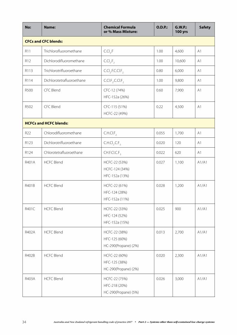
Australia and New Zealand refrigerant handling code of practice 2007 • Part 2 — Systems other than self-contained low charge systems34
No: Name: Chemical Formula or % Mass Mixture:
O.D.P.: G.W.P.: 100 yrs
Safety
CFCs and CFC blends:
R11 Trichlorofluoromethane C.Cl3.F 1.00 4,600 A1
R12 Dichlorodifluoromethane C.Cl2.F
21.00 10,600 A1
R113 Trichlorotrifluoroethane C.Cl2.F.C.Cl.F
20.80 6,000 A1
R114 Dichlorotetrafluoroethane C.Cl.F2.C.Cl.F
21.00 9,800 A1
R500 CFC Blend CFC-12 (74%)
HFC-152a (26%)
0.60 7,900 A1
R502 CFC Blend CFC-115 (51%)
HCFC-22 (49%)
0.22 4,500 A1
HCFCs and HCFC blends:
R22 Chlorodifluoromethane C.H.Cl.F2
0.055 1,700 A1
R123 Dichlorotrifluoroethane C.H.Cl2.C.F
30.020 120 A1
R124 Chlorotetrafluoroethane CH.F.Cl.C.F3
0.022 620 A1
R401A HCFC Blend HCFC-22 (53%)
HCFC-124 (34%)
HFC-152a (13%)
0.027 1,100 A1/A1
R401B HCFC Blend HCFC-22 (61%)
HFC-124 (28%)
HFC-152a (11%)
0.028 1,200 A1/A1
R401C HCFC Blend HCFC-22 (33%)
HFC-124 (52%)
HFC-152a (15%)
0.025 900 A1/A1
R402A HCFC Blend HCFC-22 (38%)
HFC-125 (60%)
HC-290(Propane) (2%)
0.013 2,700 A1/A1
R402B HCFC Blend HCFC-22 (60%)
HFC-125 (38%)
HC-290(Propane) (2%)
0.020 2,300 A1/A1
R403A HCFC Blend HCFC-22 (75%)
HFC-218 (20%)
HC-290(Propane) (5%)
0.026 3,000 A1/A1

35Australia and New Zealand refrigerant handling code of practice 2007 • Part 2 — Systems other than self-contained low charge systems
No: Name: Chemical Formula or % Mass Mixture:
O.D.P.: G.W.P.: 100 yrs
Safety
R403B HCFC Blend HCFC-22 (56%)
HFC-218 (39%)
HC-290(Propane) (5%)
0.019 4,300 A1/A1
R405A HCFC Blend HCFC-22 (45%)
HFC-142b (5.5%)
HFC-152a (7%)
HFC-318 (42.5%)
0.018 5,200 A1/A1
R406A HCFC Blend HCFC-22 (55%)
HCFC-142b (41%)
HC-600a (Isobutane) (4%)
0.036 1,900 A1/A2
R408A HCFC Blend HCFC-22 (47%)
HFC-125 (7%)
HFC-143a (46%)
0.016 3,000 A1/A1
R409A HCFC Blend HCFC-22 (60%)
HCFC-124 (25%)
HCFC-142b (15%)
0.039 1,500 A1/A1
R409B HCFC Blend HCFC-22 (65%)
HCFC-124 (25%)
HCFC-142b (10%)
0.039 1,500 A1/A1
R411A HCFC Blend HCFC-22 (87.5%)
HCFC-152a (11%)
HCFC-1270 (1.5%)
0.030 1,500 A1/A2
R411B HCFC Blend HCFC-22 (94%)
HCFC-152a (3%)
HCFC-1270 (3%)
0.032 1,600 A1/A2
R412A HCFC Blend HCFC-22 (70%)
HCFC-142b (25%)
HFC-218 (5%)
0.035 2,200 A1/A2
R416A HCFC Blend HCFC-124 (39.5%)
HCFC-134a (59%)
HFC-600 (1.5%)
0.009 1,000 A1/A1
R509A HCFC Blend HCFC-22 (44%)
HFC-218 (56%)
0.015 5,600 A1

Australia and New Zealand refrigerant handling code of practice 2007 • Part 2 — Systems other than self-contained low charge systems36
No: Name: Chemical Formula or % Mass Mixture:
O.D.P.: G.W.P.: 100 yrs
Safety
HFCs and HFC blends:
R125 Pentafluoroethane C2.H.F
50.0 2,800 A1
R134a Tetrafluoroethane C.F3.C.H
2.F 0.0 1,300 A1
R143a Trifluoroethane C.F3.C.H
30.0 4,300 A2
R404A HFC Blend HFC-125 (44%)
HFC-134a (4%)
HFC-143a (52%)
0.0 3,800 A1/A1
R407A HFC Blend HFC-32 (20%)
HFC-125 (40%)
HFC-134a (40%)
0.0 2,000 A1/A1
R407B HFC Blend HFC-32 (10%)
HFC-125 (70%)
HFC-134a (20%)
0.0 2,700 A1/A1
R407C HFC Blend HFC-32 (23%)
HFC-125 (25%)
HFC-134a (52%)
0.0 1,700 A1/A1
R410A HFC Blend HFC-32 (50%)
HFC-125 (50%)
0.0 2,000 A1/A1
R507A HFC Blend HFC-125 (50%)
HFC-143a (50%)
0.0 3,900 A1/A1

37Australia and New Zealand refrigerant handling code of practice 2007 • Part 2 — Systems other than self-contained low charge systems
16.3 Appendix 3 – Safety Group Classifications
Introduction
Refrigerants have been classified into safety groups according to the following criteria:
Classification: The safety classifications consist of two alphanumeric characters (e.g. A2 or B1). The capital letter indicates the toxicity and the Arabic numeral denotes the flammability.
Toxicity classification: Refrigerants are assigned to one of two classes, A or B, based on the following exposure:
Class A signifies refrigerants with an LC50 ≥ 10,000 ppm.
Class B signifies refrigerants with an LC50 < 10,000 ppm..
Flammability Classification: Refrigerants are assigned to one of three classes, 1, 2 or 3, based on flammability. Tests have been conducted in accordance with ASTM E681-04 Standard Test Method for Concentration Limits of Flammability of Chemicals (Vapors and Gases) except that the ignition source must be an electrically activated kitchen match head for halocarbon refrigerants.
Class 1 refrigerants are non-flammable.
Class 2 refrigerants have a lower explosive limit (LEL) ≥ 3.5% volume.
Class 3 refrigerants have a lower explosive limit (LEL) < 3.5% volume.
All flammability classes are as tested in air at 101 kPa (standard atmospheric pressure) and 21ºC ambient temperature.
Definitions of flammability differ depending on the purpose. For example, ammonia is classified for transportation purposes as a non-flammable gas by the U.S. Department of Transportation, but it is a Class 2 refrigerant.
Safety Classification of Refrigerant Blends: Blends whose flammability and/or toxicity characteristic may change as the composition changes during fractionation must be assigned a dual safety group classification with the two classifications separated by a slash (/). Each of the two classifications has been determined according to the same criteria as a single component refrigerant. The first classification listed is the classification of the ‘as formulated’ composition of the blend. The second classification is the classification of the blend composition of the ‘worst case fractionation’. For flammability, ‘worst case of fractionation’ is defined as the composition during fractionation that results in the highest concentration of the flammable component(s) in the vapour or liquid phase. For toxicity, ‘worst case of fractionation’ is defined as the composition during fractionation that results in the highest concentration(s) in the vapour or liquid phase for which the TLV-TWA is less than 400 ppm. The TLV-TWA for a specified blend composition has been calculated from the TLV-TWA of the individual components.

Australia and New Zealand refrigerant handling code of practice 2007 • Part 2 — Systems other than self-contained low charge systems38
Notes

39Australia and New Zealand refrigerant handling code of practice 2007 • Part 2 — Systems other than self-contained low charge systems
Notes

Australia and New Zealand refrigerant handling code of practice 2007 • Part 2 — Systems other than self-contained low charge systems40
Notes

