parking management system scope of work a parking... · parking management systems scope of work 2...
TRANSCRIPT

Parking Management System Scope of Work
Document type Scope of Work
Document prepared by:
Version No: v4.0
Status Final

Parking Management Systems Scope of Work
2
Document Review and Distribution
This document will be managed and controlled in terms of the ACSA IT Project Management Office document
management procedure.
Glossary
Acronym/Term Description
1D and 2D One and Two-Dimensional Bar Code Technology.
ACSA Airports Company South Africa.
ANPR Automatic Number (License) Plate Recognition [See LPR]
APS Automatic Payment Station.
B2B Bill to Bill.
BFN Bloemfontein.
Consumables or
Spares
This refers to goods or miscellaneous needed by the Parking System that must be
replaced regularly because they wear out or are used up. They are required for the
operational running of the Parking System.
CPU Central Processing Unit.
CTIA Cape Town International Airport.
DP Card Tenant/Staff Parker Card.
EFT Electronic Funds transfer.
HDD Hard Disk Drive.
HOD Head of Department.
IEEE 802.3
Standard specification for Ethernet, a method of physical communication in a local area
network (LAN), which is maintained by the Institute of Electrical and Electronics
Engineers (IEEE).
IPsec Internet Protocol Security.
IP65 IP65 Enclosure - IP rated as "dust tight" and protected against water projected from a
nozzle.
IT Information Technology.
IVERI Financial Clearing House for POF Credit card and Debit card transactions.

Parking Management Systems Scope of Work
3
KP Card Short Parker card.
KSIA King Shaka International Airport.
LAN Local Area Network.
LAN KVM Local Area Network Keyboard Video Mouse Extender.
LED Light Emitting Diode.
LPR License plate Recognition. [See ANPR]
OEM Original Equipment Manufacturer.
OHS Occupational Health and Safety Act.
OPMS Zeag specific reference to name of database.
OPMS.mdb Zeag naming reference of database that keeps record of old information for later
reference.
OPMSSS Zeag naming reference to temporary storage of database.
ORTIA Oliver Reginald Tambo International Airport.
OS Operating System
PC Personal Computer.
POF Pay on Foot.
PCU Peripheral Control Unit.
PMS Parking Management System.
PSU Power Supply Unit.
PTM Pocket Terminal.
RSS Rich Site Summary or Really Simple Syndication.
RCU Recycling Coin Unit.
RCU05 Version of RCU.
RFID Radio Frequency Identification.
RFP Request for Proposal.
SABS South African Bureau of Standards.
SLA Service Level Agreement.
SOW Scope of Work Document.
Parking Management Systems Scope of Work
4
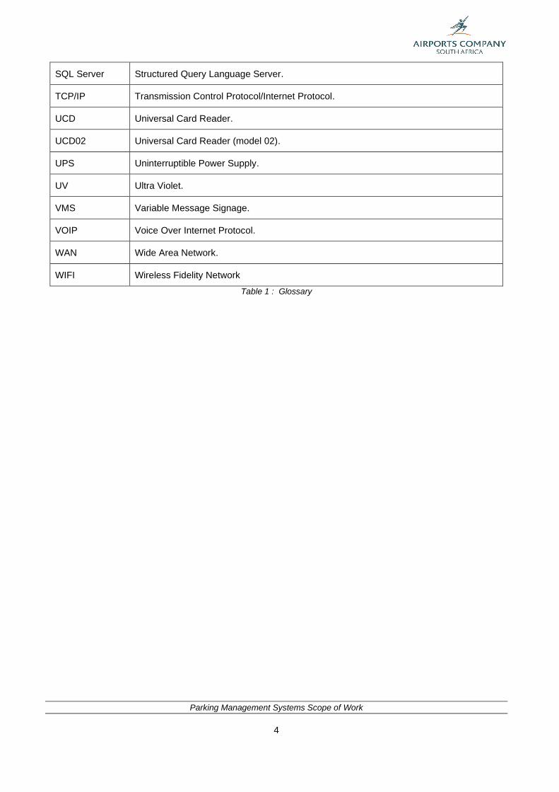
SQL Server Structured Query Language Server.
TCP/IP Transmission Control Protocol/Internet Protocol.
UCD Universal Card Reader.
UCD02 Universal Card Reader (model 02).
UPS Uninterruptible Power Supply.
UV Ultra Violet.
VMS Variable Message Signage.
VOIP Voice Over Internet Protocol.
WAN Wide Area Network.
WIFI Wireless Fidelity Network
Table 1 : Glossary

Parking Management Systems Scope of Work
5
TABLE OF CONTENTS
1. INTRODUCTION _____________________________________________________________ 8
2. SCOPE ____________________________________________________________________ 9
3. OR TAMBO INTERNATIONAL AIRPORT ________________________________________ 11
4. KING SHAKA INTERNATIONAL AIRPORT _______________________________________ 13
5. AS IS SYSTEM CONTEXT MODEL _____________________________________________ 15
6. PAY ON FOOT REQUIREMENTS SPECIFICATION ________________________________ 17
7. LICENSE PLATE RECOGNITION REQUIREMENTS SPECIFICATION _________________ 25
8. VARIABLE MESSAGE SIGNAGE REQUIREMENTS SPECIFICATION _________________ 28
9. BAY DETECTION SENSORS REQUIREMENTS SPECIFICATION ____________________ 30
10. GENERIC REQUIREMENTS SPECIFICATION ____________________________________ 31
11. SERVER SPECIFICATIONS __________________________________________________ 33
12. WORKSTATION OR CASHIER TERMINAL SPECIFICATIONS _______________________ 35
13. TICKET VALIDATORS _______________________________________________________ 36
14. FIBRE OPTIC CABLING SPECIFICATIONS ______________________________________ 36
15. REPORT SPECIFICATIONS __________________________________________________ 38
16. NON-FUNCTIONAL SPECIFICATIONS __________________________________________ 40
17. MAINTENANCE SCOPE OF SERVICES _________________________________________ 42
18. SUPPORT SERVICES _______________________________________________________ 48
19. MEETING AND REPORTING REQUIREMENTS ___________________________________ 51
20. DOCUMENTATION __________________________________________________________ 53
21. AIRPORT LAYOUTS AND SYSTEM ARCHITECTURAL MODELS ____________________ 54
22. IMPLEMENTATION APPROACH _______________________________________________ 54
Parking Management Systems Scope of Work
6
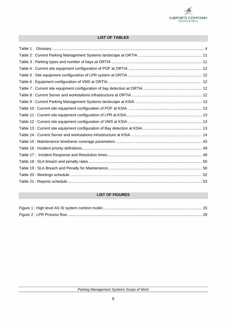
LIST OF TABLES
Table 1 : Glossary ............................................................................................................................................... 4
Table 2 : Current Parking Management Systems landscape at ORTIA ............................................................ 11
Table 3 : Parking types and number of bays at ORTIA ..................................................................................... 11
Table 4 : Current site equipment configuration of POF at ORTIA ..................................................................... 12
Table 5 : Site equipment configuration of LPR system at ORTIA ...................................................................... 12
Table 6 : Equipment configuration of VMS at ORTIA ........................................................................................ 12
Table 7 : Current site equipment configuration of bay detection at ORTIA ....................................................... 12
Table 8 : Current Server and workstations infrastructure at ORTIA .................................................................. 12
Table 9 : Current Parking Management Systems landscape at KSIA. .............................................................. 13
Table 10 : Current site equipment configuration of POF at KSIA. ..................................................................... 13
Table 11 : Current site equipment configuration of LPR at KSIA ....................................................................... 13
Table 12 : Current site equipment configuration of VMS at KSIA ...................................................................... 13
Table 13 : Current site equipment configuration of Bay detection at KSIA ........................................................ 13
Table 14 : Current Server and workstations infrastructure at KSIA ................................................................... 14
Table 15 : Maintenance timeframe coverage parameters ................................................................................. 43
Table 16 : Incident priority definitions ................................................................................................................. 49
Table 17 : Incident Response and Resolution times ......................................................................................... 49
Table 18 : SLA breach and penalty rates ........................................................................................................... 50
Table 19 : SLA Breach and Penalty for Maintenance ........................................................................................ 50
Table 20 : Meetings schedule ............................................................................................................................ 52
Table 21 : Reports schedule .............................................................................................................................. 53
LIST OF FIGURES
Figure 1 : High level AS IS system context model ............................................................................................. 15
Figure 2 : LPR Process flow ............................................................................................................................... 28

Parking Management Systems Scope of Work
7
EXECUTIVE SUMMARY
This Parking Management System Scope of Work document is a distillation of Airport assessment visits
undertaken last year (2017) between February and March. The visits were dictated and mandated by intermittent
technical and operational failures of the Parking Management Systems (PMS) in general at all Airports. Key
findings from the assessments were as follows:
1. All Regional Airports did not have a support and maintenance contract in place to ensure Service and
Operational continuity;
2. The proliferation of siloed implementation was rife and pervasive without regards or alignment to
standards or industry best practice and benchmarks;
3. The Parking Management System was not offered as a consolidated service offering which includes
Pay on Foot, License Plate Recognition, Variable Message Signage and Bay Detection as one package
that seeks to achieve the same broad objective ie seamless Parking Management; and
4. Most of the Parking Management Systems have reached the end of their useful life span and are no
longer reliable;
As a response to the non-existence of Support and maintenance contracts at Regional Airports, urgent Fit gaps
for Support and maintenance for a suitable duration inclusive of Parking consumables as a tentative solution
was put in place. The rationale for the Support and maintenance Fit gaps is to stabilise operations in order to
ensure Service and Operational continuity.
The long term sustainable solution to the preceding challenges is to comprehensively replace all Parking
Management Systems at all Airports with state of the art systems under the auspices of one Service Provider
and one Contract consistent with the IT Strategy, the new Operating model, the Governance framework and
Organisational vision in general. This document is an extensive and elaborate articulation of the Scope of Work
for the Parking Management System Replacement Project at all ACSA Airports. It commences with a succinct
expression and contextualisation of the business challenge or need, background and objectives to be achieved.
It then proceeds to unpack the scope or delimitations of the Project. The current AS IS or baseline situation at
ORTIA and KSIA from a Parking Management Systems perspective is established, documented and Airport
specific requirements captured. Next is a deployment of transversal or cross cutting functional requirements for
all Airports for the Parking Management System encompassing Pay on Foot, License Plate Recognition,
Variable Message Signage and Bay Detection. The preceding is trailed by an exposition of infrastructural or
enablement specifications including non-functional requirements. The later part of the document is a
disintegration and postulation of the support and maintenance requirements, service level agreements and
Service Provider performance requirements.

Parking Management Systems Scope of Work
8
1. INTRODUCTION
1.1. Background and Problem statement
Following assessments visits at all ACSA Airports earlier last year (2017) between February and March
regarding Parking Management Systems, it was apparent that there are serious operational challenges
owing to the age of the systems and also problems of support and maintenance. Support and maintenance
is currently non-existent and the Service Providers only support systems that are still under warranty.
Furthermore, several systems have reached end of useful life and need to be replaced due to obsolescence.
Summarily, the following challenges were uncovered:
1.1.1. No Support and maintenance contracts in place to support the Pay on Foot (POF) system or
solution. Support is mainly based on warranty and not all machines qualify for this concession;
1.1.2. No contract for Parking System consumables (spares) in place;
1.1.3. Automatic Pay Stations together with associated or related infrastructure (Intercom, Booms) were
plagued with intermittent and frequent operational and technical failures;
1.1.4. With the exception of ORTIA, CTIA and KSIA, there was no License Plate Recognition (LPR)
System at other Regional Airports;
1.1.5. Chip and Pin (debit card) as well as Credit card functionality was non-existent or dysfunctional on
the POF systems;
1.1.6. Dealing with lost tickets was a daunting challenge. Verifying whether the motorist or customer is
truthful regarding parking duration in cases of lost ticket was problematic. Staff depend on manual
capturing of car registration numbers to establish the truth. The installation of LPR will circumvent
this challenge;
1.1.7. The Service Provider installed the POF system without all related, key or associated functionality
eg Credit Card, Chip and Pin, Bill to Bill, Note Safes etc. When these functionalities were later
requested, ACSA was quoted separately;
1.1.8. Rejection of some coins and bank notes by some pay stations with no alternative option;
1.1.9. There were accessibility challenges with regards to the POF systems because they were never
designed to cater for the disabled or physically challenged individuals; and
1.1.10. Except for KSIA, all airports had one Service Provider for Parking Management Systems with
eight different contracts.
1.2. Recommendation
Firstly, against the preceding background just articulated and secondly, mindful of the need to ensure
operational continuity, improve service levels, improve customer experience, safe guard ACSA’s reputation
and parking income, thirdly, aware that Parking revenue constitutes 19% (third after Retail and Property
rental) of non-aeronautical revenue and finally, cognisance of the need to ensure long term sustainability in
this regard, the following recommendations have been made and will need to be implemented.

Parking Management Systems Scope of Work
9
1.2.1. Tentative solution
Implement urgent Fit gaps for support and maintenance for a suitable duration inclusive of parking
consumables as a tentative solution. The rationale for the support and maintenance Fit gaps is to
stabilise operations given that the National Parking initiative will take some time to be implemented
owing to project governance and procurement processes.
1.2.2. Long term sustainable solution
Replace all Parking Management Systems at all ACSA Airports with state of the art systems starting
with ORTIA and KSIA as phase one of the project. Furthermore, to ensure alignment with the IT Strategy
and new Operating model, radically convert to a new model by standardising all Airport systems as well
as consolidating and coalescing all contracts under the umbrella of one Service Provider. Transition to
the new dispensation will lead to the following benefits:
1.2.2.1. Improved visibility and better management of contracts;
1.2.2.2. Leverage on economies of scale;
1.2.2.3. A consistent look and feel for all Airport systems; and
1.2.2.4. A platform that is conducive for systems interoperability and scalability will be created that
can be leveraged upon.
1.3. Purpose of this document
The purpose of this Scope of Work (SOW) document is to articulate and concisely specify the work
activities, material or equipment specifications, deliverables, milestones, quality requirements, support
and maintenance requirements as well as performance management and evaluation criteria applicable
to a comprehensive replacement of all Parking Management Systems (PMS) at ORTIA and KSIA. This
incorporates the replacement of the following sub systems:
1.3.1. Pay on Foot inclusive of Intercom;
1.3.2. License Plate Recognition (LPR);
1.3.3. Variable message signage; and
1.3.4. Bay detection.
2. SCOPE
2.1. In Scope
2.1.1. Comprehensive replacement of Parking Management Systems at OR Tambo International Airport
including Cargo parking precinct and King Shaka International Airport;
2.1.2. The Prospective Parking Management System shall be integrated and should work seamlessly
with the current ACSA IT landscape;
2.1.3. If in future, ACSA acquires or takes over ownership of another airport for example Mthatha
airport, the contract with the current Service Provider will be revised or amended accordingly to
incorporate the acquired airport;
2.1.4. All bidders will be required to do a compulsory site inspection and investigation at all airports

Parking Management Systems Scope of Work
10
prior to submitting their proposals. They must specifically look for structural reconfigurations,
dependencies, infrastructural and other relevant requirements that ACSA may have missed.
Therefore, ACSA does not assume anything in the environment, and present the environment to
the Bidders as is. It is the responsibility of all bidders to ensure that they obtain all necessary
information needed to craft a proposal for ACSA;
2.1.5. Inferring from the forgone expression, no negotiations will be entertained post tender award on
expansion of scope, or any other factors that were not considered by the successful bidder in
proposing the Parking Management System;
2.1.6. All equipment supplied must have a minimum warranty of 5 (five) years; and
2.1.7. Replacement of the Parking Management System at Regional airports and CTIA will form phase
2 (two) of the project.
2.2. Scope of replacement
The Scope of the Parking Management System replacement is as follows where applicable:
2.2.1. The entire POF system and its associated components and peripherals;
2.2.2. The entire Intercom system and its associated components and peripherals;
2.2.3. The entire LPR system and all its associated components and peripherals. For ORTIA, the LPR
cameras will not be replaced. Only the back-end applications and any supporting infrastructure;
2.2.4. The entire Bay detection system and its associated components and peripherals; and
2.2.5. The entire VMS system and its associated components and peripherals.
2.3. Support and maintenance and Support
2.3.1 The duration of support and maintenance is 5 (five years) including the provision of Parking
System Consumables (spares). Parking consumables to include tickets, receipt rolls, printer
ribbons etc and any other spares required to operate parking system.
2.3.2 The Service provider must explicitly articulate the warranty duration on all equipment supplied.
2.3.3 The support and maintenance duration must exclude the time spent supplying and
commisioning the system as well applicable warranty period.
2.4. Definition of consumables or spares
This refers to goods or miscellaneous needed by the Parking system that must be replaced regularly
because they wear out or are used up. They are required for the operational running of the Parking
system.
2.5. Out of scope
2.5.1. Anything not explicitly mentioned herein is out of scope; and
2.5.2. Height restriction or other signage.
2.5.3. Regional airports and CTIA
2.5.4. LPR Camera’s in OR Tambo are out of scope including Facial video camera’s.
2.6. Document structure
The next sections of this document will broadly position and specify the following:
2.6.1. Functional requirements for airports in scope;
2.6.2. Generic or transversal functional requirements;

Parking Management Systems Scope of Work
11
2.6.3. Infrastructural requirements;
2.6.4. Non-functional requirements;
2.6.5. Support and maintenance requirements;
2.6.6. Service Level Agreement (SLA) and Performance management requirements;
2.6.7. Transformation requirements and the Solution implementation approach.
3. OR TAMBO INTERNATIONAL AIRPORT
3.1. Current Parking Management Systems landscape at ORTIA
Item
#
Pay on foot Intercom License plate
recognition
Variable
message
signage
Bay Detection
1. Yes. Complete
replacement
required.
Yes. Complete
replacement
required.
Yes. Partial
replacement
required.
Yes. Complete
replacement
required.
Yes. Complete
replacement
required.
Table 2 : Current Parking Management Systems landscape at ORTIA
3.2. Parking types and number of bays
Item # Car park Area Number of bays
1. KB KB1 452
2. KB KB2 495
3. Executive parking (tenant) 39
4. MSP1 L0(car hire) 111
5. MSP1 L0 Pickup 90
6. MSP1 L1(car hire) 916
7. MSP1 L2 968
8. MSP1 L2 Premium 71
9. MSP1 L2 XXL 42
10. MSP1 L3 1 013
11. MSP1 L4 912
12. MSP1 L4 Exec c/ports 81
13. MSP2 L-2 805
14. MSP1 L-1 764
15. MSP1 L-0 330
16. MSP1 L-1 500
17. MSP1 L-2 719
18. MSP1 L-3 800
19. MSP1 L-4(tenant) 781
20. MSP1 L-5 Undercover 518
21. MSP1 Open 222
22. Piazza Open 171
23. Carports (Shade West) undercover 442
24. Carports (Shade West) open 112
25. Bus Deck Bus Deck 15
26. Shade 1 Shade 1 458
27. Shade 2 Shade 2 630
28. Super South Super South 3 855
29. Total 16 312 Table 3 : Parking types and number of bays at ORTIA

Parking Management Systems Scope of Work
12
3.3. Current site configuration of POF system
Item #
Number of Entries
Number of Exits Intercom Number of Automated Pay stations
1. 56 59 192 76 Table 4 : Current site equipment configuration of POF at ORTIA
3.4. Current site equipment configuration of LPR system
Item # Number of Entry cameras Number of Exit Cameras
1. 56 59 Table 5 : Site equipment configuration of LPR system at ORTIA
3.5. Current site equipment configuration of VMS system
Item # Component Number
1. Control box 29
2. Control cards 29
3. Power supplies 29
Table 6 : Equipment configuration of VMS at ORTIA
3.6. Current site equipment configuration of bay detection system
Item # Parking Area's
Bay Sensors
Zone Boards (LED)
Control Cards
Power Supply Units
1. KB 1 464 13 13 13
2. KB 2 496 15 15 15
3. MSP 1 L 0 0 0 0 0
4. MSP 1 L 0 PICK UP 0 0 0 0
5. MSP 1 L1 979 23 23 23
6. MSP 1 L 2 1001 23 23 23
7. MSP 1 L 3 1030 23 23 23
8. MSP 1 L 4 992 23 23 23
9. MSP 2 L -2 603 11 11 11
10. MSP 2 L -1 440 11 11 11
11. MSP 2 L 0 (GROUND) 403 15 15 15
12. MSP 2 L 1 722 16 16 13
13. MSP 2 L 2 721 16 16 13
14. MSP 2 L 3 723 17 17 17
15. MSP 2 L 4 683 17 17 17
16. Total 9257 223 223 217 Table 7 : Current site equipment configuration of bay detection at ORTIA
3.7. Servers and workstations
Item #
Servers Workstations Substations (intermediary Server)
1. 2x POF 13 9
2. 2 x VMS
3. 2 X LPR
4. 2 x Credit Card
5. 1x Intercom Server Table 8 : Current Server and workstations infrastructure at ORTIA

Parking Management Systems Scope of Work
13
3.8. Structural dependencies, reconfigurations and infrastructural requirements
This refers to any civil works and structural reconfigurations that need to be undertaken to implement
the solution. None was identified for ORTIA at the time of the assessment. However, the Service
Provider will be expected to conduct a compulsory and thorough site assessment and advise whether
any structural reconfigurations or civil works within the parking precinct is required.
4. KING SHAKA INTERNATIONAL AIRPORT
4.1. Current Parking Management Systems landscape at King Shaka International Airport (KSIA)
Item #
Pay on foot installed
Intercom License plate recognition
Variable message signage
Bay Detection
1. Yes. Complete
replacement
required.
Yes. Complete
replacement
required.
Yes. Complete
replacement
required.
Yes. Complete
replacement
required.
Yes. Complete
replacement
required
Table 9 : Current Parking Management Systems landscape at KSIA.
4.2. Current site configuration of POF system
Item # Number of Entries
Number of Exits Intercom Number of Automated Pay stations
1. 16 and 19 required for the new installation.
14 and 17 required for the new installation.
There is an Intercom device at each entry and exit.
17 and 19 required for the new installation.
Table 10 : Current site equipment configuration of POF at KSIA.
4.3. Current site configuration of LPR system
Item # Number of Entry cameras Number of Exit Cameras
1. 16 and 19 required for the new installation. 14 and 17 required for the new installation. Table 11 : Current site equipment configuration of LPR at KSIA
4.4. Current site configuration of VMS system
Item # Number of displays on gantries Number of displays on information boards
1. 3 and 5 required for the new installation. 5 and 6 required for the new installation. Table 12 : Current site equipment configuration of VMS at KSIA
4.5. Current site configuration of bay sensor detection system
Item # Number of bay detection sensors
1. 58 and 1500 required for the new installation. Table 13 : Current site equipment configuration of Bay detection at KSIA

Parking Management Systems Scope of Work
14
4.6. Servers and workstations
Item # Server type and number Workstations
1. I x Primary Database Server 1. 2 x cashier workstations including
drawer for notes and coins.
2. Additionally, 4 x workstations with
Intercoms for the control room will
be required.
2. 1 x Primary Application Server
3. 1x backup Server for database and Application
4. 1x Credit Card Processing Server
Table 14 : Current Server and workstations infrastructure at KSIA
4.7. Structural dependencies, reconfigurations and infrastructural requirements
This refers to any civil works and Structural reconfigurations that need to be undertaken to implement
the solution. civil works and structural reconfigurations will need to be performed in the following
areas:
4.7.1. Pick-up zone parking facility;
4.7.2. Ground transport staging parking facility;
4.7.3. Ground transport zone parking facility;
4.7.4. Multi-storey entrance 6 of the parking facility.
4.7.5. The IT, mechanical and electrical infrastructure requirements for the above areas are out of
scope for this scope of work; and
4.7.6. In addition to the forgone articulation, the Service Provider will be expected to conduct a
compulsory and thorough site assessment and advise whether any further structural
reconfiguration or civil works within the Parking precinct is required.
4.8. KSIA specific requirements
4.8.1. Fibre installation will be required as an infrastructural requirement;
4.8.2. The entrance equipment at the Ground Transport Zone and the Ground Transport Staging
area will not require a magnetic stripe ticket dispenser. These areas will only allow entry by
means of long and short-range RFID reader incorporating Wi-Fi and Bluetooth functionality, chip
and pin card, tap and pay technology and Automatic Licence Plate Recognition (ANPR);
4.8.3. All exit lanes will be equipped with a double barrier arm system to prevent tail-gating with the
exception of the Ground transport zone that will be equipped with a single barrier arm;
4.8.4. Two additional pay stations will be added to the multi-storey parking facility ground floor area
(level 0);
4.8.5. The ground transport vehicle zone and ground transport staging area entry lanes will only
allow access to users registered on the central POF system through wireless contact card
(RFID card, MiFare or similar), automatic license plate recognition, debit or credit card, long
range and short range RFID tags. The entry stations for the ground transport vehicle zone
must be suitable and accessible for buses and minibuses;
4.8.6. The elevated road area has a barrier arm that is in very poor condition. The barrier arm is to
be replaced with a new, quick open and closing barrier arm. The barrier arm will be a standalone
device and not be connected to the POF central system. The barrier arm will be equipped with a

Parking Management Systems Scope of Work
15
push button and a remote-control receiver and transmitter with a range of at least 50 m to operate
the barrier arm;
4.8.7. The entry and exit stations for the elevated road must be suitable and accessible for buses and
minibuses;
4.8.8. The elevated road should have the following equipment linked to the parking management system
and allow access to users registered on the central POF system through wireless contact card
(RFID card, MiFare or similar), automatic license plate recognition, debit or credit card, long range
and short range RFID tags;
4.8.8.1. Entry station;
4.8.8.2. Entry boom;
4.8.8.3. Automatic license plate recognition entry;
4.8.8.4. Exit station;
4.8.8.5. Exit boom; and
4.8.8.6. Automatic license plate recognition exit.
5. AS IS SYSTEM CONTEXT MODEL
Figure 1 is a high-level Parking Management System AS IS system context model.
Pay on FootLicense Plate
Recognition
Bay Detection SensorsVariable Message
Signage
License plate number
Ticket number
Decrement and increment
Number of available parking bays
Decrement and increment
Number of available parking bays
Figure 1 : High level AS IS system context model
The following paragraphs are a high-level expression how the Parking Management System at ACSA currently
functions.

Parking Management Systems Scope of Work
16
Entry
Step 1
When the motorist presses the button upon entry, a ticket number is generated by the POF system and sent to
the LPR system. The LPR system receives the ticket number and combines it with the License plate number
(simultaneously captured) of the car sends it back to the POF system via a Serial connection. POF then uses
this information (Ticket number + License plate number) and generates a ticket that is time stamped and the
boom opens.
Step 2.1 (Parking precinct where there are no bay detection sensors installed)
In parking precincts where there are no bay detection sensors, immediately the boom opens and the car enters
the precinct, the POF system sends a message to VMS system to decrement the number of available bays by
1.
Step 2.2 (Parking precinct where bay detection sensors installed)
Motorist enters parking precinct and parks. The Bay detection system sends a message to VMS to decrement
the total number of available bays by 1.
Exit
Step 3
When the motorist inserts the ticket upon exit, the POF system checks the following:
• Whether payment has been effected; and
• It communicates with the LPR system to verify whether the credentials on the ticket matches the ones
on the system. If there is a match, the boom opens and the motorist leaves the parking precinct.
On the contrary, if there is a mismatch or discrepancy, the system must function as specified in section 7.9.11
Step 4
Immediately the boom opens and the motorist is leaving, the POF system sends a message to VMS to increment
the number of available bays by 1.
Spike Grippers
The mechanical and functional dynamics of the spike grippers must allow the car to be able to enter and exit the
parking area in cases where there is no exception. Spike grippers are used to enforce one way traffic in a single
traffic lane, such as the entrance or exit to a parking lot.
5.1. The Intercom sub-system is an integral part of the Parking Management System even though it is not
depicted in figure 1 for simplicity sake. An intercom system is a two-way communication electronic device
that contains circuitry for the purpose of transmitting and receiving audio and/or video transmissions. In the
case of parking, it provides a medium or platform of communication between the customer or operator and
the Control room attendant; and
5.2. The Intercom subsystem must be linked to a cordless phone to allow communication between customers
and an Operator and Operator to Operator. Intercoms should have volume controls. Furthermore, they
should have call stacking capabilities in order to show and inform customers position in queue. (eg you
are number 2 on the list; your call will be answered shortly). Moreover, information should be available to
control room regarding the number of calls waiting in queue.

Parking Management Systems Scope of Work
17
6. PAY ON FOOT REQUIREMENTS SPECIFICATION
This section is an elaborate exposition of Parking Management System (PMS) requirements and specifications
that the solution must comply with. PMS as used in this document refers to the following:
I. Pay on Foot (POF) System and associated components and peripherals;
II. License Plate Recognition (LPR) associated components and peripherals;
III. Variable Message Signage (VMS) associated components and peripherals; and
IV. Bay detection sensors associated components and peripherals.
A Pay on Foot system requires the driver to pay at a payment machine before returning to their vehicle. It is a
natural solution for parking facilities such as airports, hospitals, large shopping centres, theatres and cinemas
where parking personnel are less frequently available. The POF system must at minimum comply with the
following requirements:
6.1. POF system specifications and requirements: Entry and Exit
6.1.1. The entry lanes will require a ticket dispenser, a barrier arm and barrier (single barrier arm),
and a LPR camera for each lane. The entry lanes will also be equipped with magnetic loops
to sense vehicles in order to ensure correct operation and timing of the entry lane. Pinhole facial
cameras are also required for the entries and exits;
6.1.2. Lane exits and lane entries shall be equipped with vehicle barrier systems to prevent
unauthorised exits and entries. Vehicle barrier systems shall incorporate electro-mechanical
drive units to allow automatic and manual opening and closing of barrier arms. Automatic
operation shall be the primary mode of operation for the vehicle barrier system;
6.1.3. The vehicle barrier system shall be a cost-effective solution that caters for high frequencies of
vehicular movement yet requiring minimum maintenance;
6.1.4. Electronic control panels are to be positioned within vehicle barrier cabinet at a height that
permits easy access to components and therefore allow convenient carrying out of settings
and maintenance activities;
6.1.5. All Exits, Entries and Pay stations must have proximity readers. A proximity reader is a
contactless smart card which can be read without inserting it into a reader device, as required by
earlier magnetic stripe cards such as credit cards and "contact" type smart cards;
6.1.6. The booms must preferably be padded ie covered with a soft material to protect them and
make them more comfortable and durable;
6.1.7. It shall be possible to integrate vehicle barrier systems with inductive loop detectors for
detection of vehicle presence. Logging of events at each vehicle barrier shall be made possible.
Events such as operational failure, tampering, changes in settings, and maintenance activities
shall all be reflected in the POF system as a log and accessible by ACSA when required;
6.1.8. All ticket dispensers, exit dispensers and boom housings should be in stainless steel;
6.1.9. The ticket dispensers will require a VOIP intercom system, a magnetic stripe ticket dispenser
with ability to print unique 1D and 2D bar codes, chip and pin card readers, tap and pay
technology, a pinhole camera, a RFID reader incorporating Wi-Fi and Bluetooth functionality,

Parking Management Systems Scope of Work
18
and a voice guidance system. An A5 cut-out display area covered in UV protected clear
material to accommodate the parking tariff signage. An A4 cut-out display area covered in UV
protected clear material to accommodate the entrance disclaimer signage;
6.1.9.1. VOIP intercoms are mandatory for communication purposes in the event that the
station has either swallowed a ticket, hasn’t issued a ticket or for general issues
that require communication with the respective control room operations staff;
6.1.9.2. Magnetic stripe tickets are mandatory entrance requirement in the absence of
any other means discussed below;
6.1.9.3. 1 and 2D bar code scanners scan bar codes printed either on paper, and/or read
off from mobile phones when making pre-bookings;
6.1.9.4. Chip n Pin card readers are used to read payment by debit card method;
6.1.9.5. Tap ‘n Pay technology. This technology provides a wide spectrum of uses ranging
from tap Master and VISA cards to future bus cards, city cards that will be accepted
on bus/train platforms, suitable for Park ‘n Ride solutions;
6.1.9.6. Pin-hole cameras already being installed at ORTIA, also called facial cameras will
take an image of the driver and compare entry and exit data for authentication
upon exit, preventing vehicle theft;
6.1.9.7. RFID Readers facilitate entry by prepaid card systems, or RFID tag systems that
will allow staff etc to enter and exit;
6.1.9.8. Wi-Fi and Bluetooth Technology promote the concept of BOYD [bring your own
device] methodologies, eg. Mobile phones. Enter by either placing mobile phone
against the readers, or allowing the Wi-Fi signal to lock on and authenticate and
enter via ticketless entry;
6.1.9.9. Voice guidance system. This is a sound byte that is installed into the intercom
server that allows the intercom speaker to address the motorist customer when
they activate/arm the entry station as the car drives up to the entry; and
6.1.9.10. A5 cut-out is for the purposes of applying tariff advice.
6.1.10. The exit lanes will require a ticket reader, barriers and barrier arms, and a LPR camera for
each lane;
6.1.11. The ticket readers at exits will have a VOIP intercom system, a magnetic stripe ticket and 1D
and 2D bar code reader, chip and pin card readers, tap and pay technology, a pinhole camera,
a RFID reader incorporating Wi-Fi and Bluetooth functionality, and a voice guidance system.
An A5 cut-out display area covered in UV protected clear material to accommodate the parking
tariff signage;
6.1.12. There must be an Intercom at each entry and exit. The intercom subsystem must have audio
recording and playback capabilities;
6.1.13. All exit lanes will be equipped with a double barrier arm with spike grippers system to prevent
tail-gating and all automatic barrier arms with will be of the fast-acting type;
6.1.14. Exit stations shall be automatic devices that perform parking ticket validations with a high level

Parking Management Systems Scope of Work
19
of accuracy and reliability. Exit stations shall perform quick ticket validations and quick ticket
jam detections;
6.1.15. Coordination of exit stations with vehicle barrier systems in exit lanes shall prevent vehicles
with non-validated parking tickets from exiting the parking facility and only permit vehicles with
validated parking tickets to exit. The process of validating parking tickets, offering customer
assistance through built-in intercoms and granting permission to vehicles to exit the parking
facility shall not introduce hindrances to seamless operation of exit lanes;
6.1.16. Exit stations shall make use of latest applications and component technologies that comply
with relevant national and international standards;
6.1.17. The POF system must create and maintain an audit log for instances where the boom was
manually opened at the exit;
6.1.18. Audit logs to include log of the name of operator logged in on the parking system when boom
was manually opened. All doors to have a sensor to record all manual interventions, removal
of ticket jams, etc. Exit and entry equipment to have an alarm. Audit logs to record all and be
able to extract information on specific events;
6.1.19. The numbering of tickets for all entries must be sequential;
6.1.20. The front panels of exit stations shall be made of high-quality vandal-resistant material and
comprise clear and user friendly interfaces with easy to follow instructions. It shall be possible
to transmit exit lane data (e.g. event logs, transactions etc.) to the central server for verification,
statistical analysis and storage;
6.1.21. All exit stations shall have local off-line capabilities in the event of a communications failure.
The exit stations shall store no less than 50 000 transactions and upload transactional data to
the appropriate processing system once communication is restored;
6.1.22. RAM or bollard protection of devices against damages from vehicles at entrance and exit
terminals as well as car park barriers shall be provided. The ticket dispensers, exit stations
and LPR cameras shall be protected. Protection shall be in the form of a steel post ram
protection, surface with durable, weather resistant powder coating installed using stainless
steel fitment to prevent corrosion;
6.1.23. The POF field equipment will be provided with UPS backup power, 2KvA minimum installed
inside the entry, exit and pay-station device. All server racks to have a managed 1 X 4KvA
rack-mount UPS per rack as a minimum requirement;
6.1.24. The contractor will be responsible for all equipment installation including civil works or
structural reconfigurations, cabling (fibre, ethernet, and power), etc. as described in this
document;
6.1.25. The system will include control computers to be installed in the Airport control centre to monitor
activities in the parking in case of emergency and customer issues;
6.1.26. The POF system should have the functionality that facilitates the control room operator to see
the content of the pay station eg change availability.
6.1.27. The control room operator should be able to close or reset the entry/exit station and the pay

Parking Management Systems Scope of Work
20
station from remote.
6.1.28. The interlocking area between the boom or barriers must have two robots that should glow
RED by default and should turn GREEN upon entry if the entry transaction is successful. The
two exit robots should also be RED by default and should turn GREEN upon exit if the exit
transaction is successful;
6.1.29. All entries must have spike grippers and all exits must have double spike grippers to avoid tail
gating;
6.1.30. The POF system must accept credit and debit cards, magnetic stripe tickets, and the ability to
integrate with standard parking payment application systems and bar coded paraphernalia;
6.1.31. All entry and exit lanes are to cater for License plate recognition and automated vehicle barrier
systems;
6.1.32. All entry Ticket dispensers must have a DUAL ticket storage (1 X Active storage and one
standby storage) with DUAL feeder technology that will automatically change ticket source
when tickets in active box are depleted and commence using the standby box seamlessly
without a need for operator intervention. System must report to user when the standby box of
tickets has been initiated; and
6.1.33. CCTV to pop up on screen when a specific entry, exit or pay station is activated by the control
room operator and
6.1.34. If tickets are unreadable; the exit station should still be able to ingest the ticket before the
boom is manually opened by the control room.
6.1.35. Exit station should have the functionality of paying for a parking ticket using the credit card
6.1.36. The POF system should be able to accommodate tap and pay at predetermined parking
areas like pre-booking.
6.2. POF system specifications and requirements: Pay stations
6.2.1. All pay stations shall be fully automated pay-on-foot machines that offer complete ticket
handling capabilities for central cashiering parking operations. The pay stations shall be low-
maintenance and reliable with weather-proof cabinets and vandal-resistant faceplates;
6.2.2. The pay stations shall comprise user friendly interfaces with clear instructions for guiding
customers through all payment procedures. The exterior operator controls shall be clearly laid
out with easy-to-follow instructions, visual displays and push button controls;
6.2.3. The pay-station to have an A5 cut-out display area covered in UV protected clear material to
accommodate the parking tariff signage;
6.2.4. Each pay-station to have an active media screen of no less than 15” to provide the customer
with updated electronic information using RSS feeds with central advertising capability;
6.2.5. Comprehensive cash audits and revenue management reports shall be captured on-line and
off-line to ensure 100% collection of all parking fees. Access to cash handling systems (banknote
and coin vaults) shall require electronic password or mechanical keys. Different passwords or
access keys shall be used for cash handling units and ticket containers. Each module shall be
monitored electronically for maximum security. Any unauthorised access to cash handling

Parking Management Systems Scope of Work
21
modules and ticket containers modules shall trigger an alarm and reflect immediately in the POF
system database;
6.2.6. A pinhole camera is to be installed into each pay-station to record the passengers face when
concluding a payment and an image stored with the unique ticket information and accessible
on demand;
6.2.7. All transactions processed by pay stations shall reflect immediately in the POF system
database. in the event that a customer requires assistance at a pay station, it shall be possible
to contact system operator through a built-in VOIP intercom device;
6.2.8. Pay stations shall be equipped with electronic monitoring devices to detect tampering and
misuse. Incidents of tampering and misuse shall be automatically logged and reported to the
central POF system immediately;
6.2.9. All Pay stations must incorporate Bill to Bill (B2B) functionality. B2B is a component of the pay
stations that uses bills paid with by previous customers to pay back change in bills to
subsequent customers;
6.2.10. Provision must be made for a spare note and coin safes for each pay station;
6.2.11. All pay stations shall only be opened by authorised personnel using a two-method system of
Key and a RFID card releasing a Mag-Lock mechanism. The authority levels are to be set on
the main Server and only by an Administrator. Reports indicating opening activity must be
available on the system reporting menu;
6.2.12. Each pay station shall be equipped with a static label displaying a message (written in boldface
letters) such as ‘PAY-HERE’/’ PAY STATION’. In addition, the solution must provide APS
machines that have engraved signage like for example ‘press for receipt’, ‘INSERT YOUR
CREDIT’, ‘DEBIT CARD HERE’;
6.2.13. All pay stations shall have local off-line capabilities in the event of a communications failure
The pay stations shall store no less than 50 000 transactions and upload transaction data to
the appropriate processing system once communication is restored;
6.2.14. Pay station must be able to issue vouchers if unable to dispense change;
6.2.15. In every cluster of pay-stations, there should be one which is disabled-friendly, with a reduced
height. In the event of a single installation, then it must meet the needs of people with
disabilities;
6.2.16. All parking pay stations must allow for float refilling externally through either the coin slot
for the topping, up of change in the various denominations into the coin hoppers/containers or
via the note acceptor for the refilling of the note storage facility;
6.2.17. Regarding note acceptance, the payment stations must accept all notes as released by the
South African Reserve Bank and acceptable in South Africa as legal tender. Upon a change
of currency notes as may be decided upon by the Governor of the Reserve Bank, such
changes must be successfully implemented into the parking payment stations nationally, within
a period of 14 days from date of release of the new notes;
6.2.18. Pay stations must be able to dispense change in notes and coins. Notes and coins received

Parking Management Systems Scope of Work
22
to be recycled to issue change. In addition, provision must be made for coin storage in hoppers
or similar device;
6.2.19. Loss of data or Information should be retrievable on Server if memory is lost due to some
malfunction of pay stations;
6.2.20. It is a mandatory requirement that the system be equipped with functionality that will enable
the motorist or customer to be able to pay at the EXIT with a debit or credit card upon leaving
the parking precinct;
6.2.21. Mobile payment: The mobile payment functionality should ideally or preferably work as per the
following two scenarios:
6.2.21.1 Scenario 1
With this scenario, payment will be effected will by way of a downloadable application to be provided
the Service Provider. The application will work in conjunction with ACSA branded cards to be
provided by the Service Provider. The trigger of the payment mechanism will be the ACSA cards.
Payment will be done online via the application using a debit or credit card and entry and exit via the
parking precinct will unfold by via the ACSA cards.
6.2.21.2 Scenario 2
To pay using a phone, motorist scan a quick response (QR) code on their parking ticket using an
application to be provided by the Service Provider that can be installed on mobile devices, there after
the ticket number or licence plate number is entered and payment concluded via debit or credit card.
Upon leaving the parking precinct the motorist presents the ticket at the exit and leave.
6.3. POF system specifications and requirements: Ticketing and Printing technology
6.3.1 The system will use magnetic stripe tickets and have the ability to scan and read bar coded
paraphernalia, issued to customers via the entry stations or in the event of bar codes, obtained
from various approved sources, payable at the pay stations and used at the exit stations;
6.3.2 The system must accept chip and pin cards, credit cards and tap and pay and RFID
technology devices at the entrance and exit stations, with the specific card or device acting as
the ticket creating a ticketless environment, payment must be automatically calculated at exit,
and the transaction concluded from the card or similar device used upon entry. The exit stations
will accept payment at the exit station from a magnetic stripe ticket;
6.3.3 The Parking Management System will allow for the creation of customer accounts. The
customers with accounts will be issued with wireless RFID cards. The RFID cards will allow
entrance and exit to all parking areas connected to the POF system, with the accounts
automatically updated with the associated fees. Customers with created accounts will also be
able to add more vehicles and link to their accounts;
6.3.4 Users will be issued with monthly account statements via e-mail. Account holders will be able
to make payments to their accounts via EFT, payment at the cash registers, or by means of
their RFID cards at the pay stations;
6.3.5 ACSA has entered an agreement with the Republic of South African Parliament of South Africa

Parking Management Systems Scope of Work
23
to provide the Members of Parliament with ease of access in the use of a ‘one-card-all-airports’
facility, the technology design in the tender response must be able to fully integrate into the
current offering to Parliament without having the need to issue additional cards;
6.3.6 Ticket dispensers shall use the latest components and applications that comply with relevant
national and international standards. Components shall be of high quality and be able to
withstand severe weather conditions. It shall be possible to integrate ticket dispensers with third-
party devices at entry lanes to achieve a fully automated vehicle access control system;
6.3.7 Parking tickets shall be issued at all ticket dispensers located at all entry lanes with the
exception of the vehicle staging and the bus lane;
6.3.8 Pay stations and the cashier terminal shall issue replacement parking tickets for lost tickets and
for tickets that become unreadable. Furthermore, bidders must provide a process for ticket re-
issue that will avoid fraudulent activities and also avoid criminal activities, e.g. aimed at stealing
cars;
6.3.9 Printing and reprinting options from the control room of receipts shall be made possible at all
designated pay points and exit points;
6.3.10 The minimum information to be printed on the parking tickets shall be the Name of the Airport,
Ticket Number, Entry Time, Entry Date and Name of the Entry Point;
6.3.11 Additional information that may be considered mandatory to appear on the tickets shall be
accommodated by the Service Provider;
6.3.12 The license plate associated with the ticket shall be printed on the ticket;
6.3.13 The minimum information to be printed on receipts shall be Name of the Airport, Location within
the parking facility, Duration, the words ‘tax invoice’, Receipt date and time; License Plate
Number (optional) and Transaction type i.e. cash, credit/debit card or contactless card, the value
of the transaction;
6.3.14 Receipts should have a VAT number;
6.3.15 The central control room operator must be able to reprint receipts using a facility on the
workstations in the control room to either a pay-station or to an exit station and have the option
to e-mail the receipt directly from the workstation; and
6.3.16 There are a lot of system reports that are printed from the POF system to reconcile the revenue
and other parking statistics. It would be preferred that the POF system be linked to the ACSA
printers to print these reports as the printers supplied by the service provider use up the ink
quite quickly and the cartridges are expensive. If the system reports are not linked to the ACSA
printers for printing, the POF service provider must include the supply of printer cartridges as
part of their monthly consumable list. Reports should be e-mailed via POF to dedicated e-mails
and team viewer to remotely dial in and extract them.
6.4. Customer loyalty programs and discounted parking fees
Prospective bidder’s proposal must incorporate a value proposition of the concept of loyalty and
discounts on parking fees. In other words, the proposed parking management solution must be able to

Parking Management Systems Scope of Work
24
integrate and function seamlessly with existing and envisaged customer loyalty programs at ACSA in
a manner that customers and motorist can qualify for discounted parking fees.
6.5. POF system specifications and requirements: Cashier workstations (Terminals)
6.5.1 The manual cashier terminal shall offer similar manual car park tolling services. The
equipment and software shall be flexible and capable of customisation to meet the
specific requirements as detailed in this section;
6.5.2 The cashiering system equipment and software must not operate as stand-alone units.
They will be networked to share the POF system central server database. Upon a network
failure, only will the cashier station operate on standalone and should be able to hold no less
than 50 000 transactions;
6.5.3 The cashier stations will also be equipped with a receipt printer and an A4 printer and
a VOIP intercom system;
6.5.4 Cashier work stations must be able to print duplicate receipts for all payments made at
exits and Pay stations;
6.5.5 The operating stations will each include a master VOIP intercom station which will be
connected to the intercoms located at the entry stations, exit stations, and pay stations.
6.5.6 All computer workstations are to be rack-mounted in a secure IT room and fed through
to the control centre by the use of LAN KVM extender technology; and
6.5.7 All computer workstations are to be rack-mounted in a secure IT room and fed through
to the control centre by the use of LAN KVM extender technology.
6.6. Car Charging Stations
6.6.1 The POF system should have the ability to add on parking power charging stations as and
when requested for electric vehicles and be able to transact amounts payable in currency
at pay-stations or at the charging station itself;
6.6.2 The solution must be able accommodate ‘pay-as -you-go’ or similarly, prepaid recharging
stations for electric vehicles that is fully integrated with the parking software and hardware;
and
6.6.3 The Car battery charging stations should have a variety of connections to meet with
international and industry specific requirements.
6.7. Pre-booking
6.7.1 The POF system shall be able to accommodate prebooking options into all parking
facilities, and maintain an accurate update of bays used versus bays available which will
be communicated in real-time to the embedded prebooking portal; and
6.7.2 As an innate requirement, the POF system should have an application through which
mobile users will be able to log on remotely to their profiles and prebook a bay in a
parking facility and enter the facility by way of their mobile phone RFID, bar coded receipt
displayed on their mobile device, or through printed paraphernalia.

Parking Management Systems Scope of Work
25
7. LICENSE PLATE RECOGNITION REQUIREMENTS SPECIFICATION
The objective of this system is to minimise crime and mitigate the phenomenon of car theft and revenue
leakage. LPR is an image processing technology used to identify vehicles by their license plates on entry
and at exit time to ensure the car license plate matches the parking ticket. The technology is supported by
complimentary processes which match license plate registration, facial image of the motorist and the
payment transaction. This makes it difficult for a motorist to drive out of the parking precinct if transaction
credentials upon exit do not match the entry ones. In case of a mismatch or discrepancy, the system must
function as specified in section 7.20.11. The LPR system must at minimum comply with the following
requirements:
7.1. Each parking entry and exit lane at the airport parking facilities shall be equipped with the LPR
subsystem;
7.2. The LPR subsystem shall consist of all hardware and software necessary to provide a complete licence
plate reading subsystem that does not adversely affect any function of the POF system;
7.3. The Service Provider shall be responsible for providing fully functional LPR subsystem that is fully
integrated with the rest of the Parking Management System;
7.4. Processing of license plates by the LPR subsystem shall occur in parallel with other functions occurring
at exit and entry lanes. Operation of the LPR subsystem shall not negatively impact the ticket
processing time for vehicle entry and vehicle exit;
7.5. All Cameras for the LPR subsystem must be digital and IP based;
7.6. LPR cameras should be in a tamper plate housing to prevent the camera from being bumped and
loosing focus;
7.7. The LPR subsystem must have LPR and facial cameras at all entries and exits;
7.8. All information within the LPR database shall be accessible for review on a screen and through the
availability of printing of reports. No impediment to the immediate access and retrieval of LPR data
shall result from the use of the POF system database or any other system hardware or software;
7.9. The proposed Automated Number Plate Recognition Software (ANPRS) or Automated Licence Plate
Recognition System (ALPRS) should be a stand-alone application which should be able to function in
the absence of any integration with Pay on Foot/Parking Management/Access control or any State
Agency Institutions;
7.10. The proposed system should play a role of an intelligence system when integrated with
critical Airports systems (Pay on Foot, Access Control or any other State Agency Systems);
7.11. It should deliver clear license plate images for reliable recognition, in both highest levels of glare and
in the darkest hours;
7.12. The system should be able to integrate with any Pay on Foot System/Parking Management
System/Pay per parking/Access Control and or State Agency systems;
7.13. The system should be able to determine the car mark and brand;

Parking Management Systems Scope of Work
26
7.14. It should be able to integrate with multiple with multiple cameras including drive face camera, overview
camera and number plate camera;
7.15. When integrated with Pay on Foot, the ANPRS/ALPRS should be able to provide statistics on overstay;
7.16. It should be able to White list or Blacklist so that authorised vehicles can easily pass;
7.17. It should have built in or an alternative monitoring system to detect when there is an offline facial and
LPR camera;
7.18. Other system features should include the following:
7.18.1. Identification of Vehicle make and model;
7.18.2. Accurate License Plate Recognition;
7.18.3. Number plate and vehicle mismatch scenario; and
7.18.4. Drive and vehicle mismatch scenario.
7.19. LPR Camera specifications:
7.19.1. Must be able to capture a vehicle Licence plate at up to 20MPH (32km/hr);
7.19.2. Must have Supreme anti-glare capabilities/build in illumination/ Capability to read reflective and
no reflective license plate;
7.19.3. Must be open IP standards for plug-and-play integration with 3rd party Automatic Number Plate
Recognition Software (ANPR) or Automatic Licence Plate Recognition;
7.19.4. Must be dust and waterproofed resistant;
7.19.5. Must Activate detection via software video motion detection or by input/output activation;
7.19.6. Power: POE/POE+++/802.3AF/12V/24VAC;
7.19.7. 1080P/2 Megapixel;
7.19.8. Detection rate must be greater of equal to 99%;
7.19.9. Reading rate must be greater or equal to 95%;
7.19.10. Black and White and colour option;
7.19.11. Optical character recognition (OCR) Engine Onboard;
7.20. In conjunction with the POF system, the LPR subsystem must at minimum be able to work as follows:
Step 1: Entrance to parking precinct
7.20.1. The motorist presses the button on the ticket dispenser, this action activates a process,
whereby the facial camera takes the picture of the motorist, simultaneously the LPR camera
positioned in front of the boom will decode, read and store the registration number and captures
an image of the vehicle license registration plate. In a ticket-less environment or prebooked
scenario, the LPR immediately recognises the licence plate via the RFID used by either mobile
phone technology or by prebooked and prepaid criteria and opens the boom, sending a string of
the information gathered to the database for storage and billing purposes;
7.20.2. The motorist picture and the vehicle license registration plate is matched and stored in the
system;
7.20.3. A parking ticket is printed and issued to the motorist, the ticket issued contains the details of
the boom/entrance, date, time and registration number printed on it; and

Parking Management Systems Scope of Work
27
7.20.4. The boom opens and allows the motorist to enter the Parkade.
Step 2: Payment for parking
7.20.5. Before leaving the airport, the visitor/motorist pays for parking time at the automatic payment
station (APS) located within the airport precinct which registers the payment;
7.20.6. At the APS, the motorist inserts the parking ticket. The system computes the cost and displays
it on the screen; and
7.20.7. A successful transaction is registered on payment and is registered as paid in the system. The
parking ticket is validated and re-issued to the motorist;
Step 3: Exit from parking precinct
7.20.8. The motorist inserts the ticket into the ticket acceptor slot and this activates a process whereby
the payment, license plate registration is matched via the POF system. In a ticketless
environment, the LPR would immediately recognise the licence plate and RFID apparatus,
check for available funds or prepayment and evaluate the stay period against the funds and
opens the boom to allow exit;
7.20.9. If all the above-mentioned characteristics or variables are matched, the first boom opens
allowing the motorist to proceed into the interlocking area between the two booms; and
7.20.10. Once the first boom closes after the motor vehicle has passed through, the second boom will
open allowing the motor vehicle to exit from the Parkade. As the ticketless user leaves the
parking facility, the POF system will automatically generate a tax invoice for the stay period and
send to the user via email.
Exception: Credentials discrepancy
7.20.11. If a mismatch is detected between parking ticket and vehicle license plate number, the
following must unfold:
14.9.11.1 The system must raise an alarm;
14.9.11.2 LPR should automatically pop-up both entry and exit pictures of the vehicle
registration and the driver (Facial Recognition);
14.9.11.3 LPR should show colour/make of the vehicle without the Control room agents
looking at CCTV footage;
14.9.11.4 The vehicle registration (automated pop-up) should be time stamped with date and
time as well as entry used.
14.9.11.5 As the above articulated events (14.9.11.1 to 14.9.11.4) are unfolding, the system
should maintain a high level of operational ability without any reduction in processing
capacity.
7.20.12. Furthermore, in case of exceptions of the above nature, a log must be automatically generated
in an incident file and stored for auditing purpose. The LPR process articulated above is
depicted in figure 2 at a high-level. The process model does not cover the ticketless scenario.

Parking Management Systems Scope of Work
28
Number Plate?Capture number
plate
Trigger camera for
plate recognition
Detect Plate
characters
Record date, time,
vehicle registration
number, gate
number
Insert Ticket/Press
for ticket
Yes
Print and Issue
TicketOpen Boomgate
Yes
Exit/Entrance?
Entrance
Compare record in
databaseExit
Check payment
and time
Correct?Open Exit boom Yes
Raise Control
Room Alarm
NO
Record date, time,
number, gate
number
No
Stop
Start
Sensor picks
vehicle?
No
Figure 2 : LPR Process flow
8. VARIABLE MESSAGE SIGNAGE REQUIREMENTS SPECIFICATION
The purpose of the VMS system is to assist motorists driving into the Airport to be able to see, from a
distance, how many parking spaces are available at which parking precinct and therefore where parking can
be found when they are still out of the parking precinct.
8.1. Variable message signage: Signage
8.1.1. The Variable Message Signage (VMS) shall provide motorists with information they need to
choose a parking area and parking product. The information shall help motorists to quickly locate
correct parking structures, level and space where they are parked. The static signage to include
parking grading requirements to indicate best choice options by virtue of convenience;
8.1.2. The VMS shall conform to applicable design standards with regards to text height, arrow style,
colour usage and the use of sign faces;
8.1.3. The VMS shall ensure logical decision making process for both arriving and departing motorists.
Information shall be provided instantaneously, at the correct location, with accurate values, and
in a format, that is clearly understood by the viewer. The system shall make use of consistent
terminology on signage and use of terms most commonly understood by motorists;
8.1.4. The VMS system displays must respond appropriately to ambient light intensities between full
sunlight and complete darkness for maximum visibility. The VMS system shall ensure that the
luminance output of the display board elements is maintained in accordance with ambient light
conditions, especially when there is low sun directly in front of, or low sun directly behind the VMS;
8.1.5. The VMS control unit shall provide information regarding the Power failure, communication

Parking Management Systems Scope of Work
29
failure, incorrect message displayed, message updated, external luminance level (lux) and
luminance settings;
8.1.6. The VMS will be fully networked and configurable through the control centre. The VMS will
provide real time parking space availability. Dynamic Information displayed by the VMS will
reflect immediately in the POF system. Where necessary, it will be possible to configure to display
appropriate messages for special events such as lane closures, special tariff structures etc.to the
POF system; and
8.1.7. Real time logging of events will be possible through VMS controls units. Logged data will include
dysfunctional units, error messages, changes in settings, maintenance activities etc. Such data
will be reflected in the POF system database.
8.2. Variable message signage: Applications
8.2.1. Vehicle directional signage: This will provide motorists with directions for ease of navigation at
identified locations throughout the parking facility. Directions will be in the form of names of
parking areas and arrows next to the names pointing in the direction of the parking area locations.
The signage will display parking space availability of parking space by area. Dynamic information
relating to parking products such as tariff structures and grace periods will form part of the
information provided by vehicular directional signage. Location of vehicular direction signage will
be next to identified roadways within and outside the parking facility. Where over-head mounting
of signs are unnecessary or impractical, post-mounted signs will be used next to the roadways.
Material will be fabricated aluminium with applied retro-reflective graphics and digital LED
displays. External over-head light fixtures will be provided for night time illumination of the entire
signage display boards. The signs will be attached to galvanized steel/post structures;
8.2.2. Facility identification signage: This will be wall mounted and easy to locate by motorists.
Information displayed will be the name of the parking area (e.g. ‘MULTI-STOREY PARKADE
ENTRANCE 1’) at the entrance. Where wall-mounted signage is not possible, free-standing or
post-mounted signs will be installed next to the facility entrance. The signage will be made out of
fabricated aluminium with applied retro-reflective graphics. External lighting will be provided for
night time illumination of the signage boards;
8.2.3. Facility interior signage: Shaded parking facility and the Multi-storey parking facility interior
signage will provide directional information to guide motorists through the parking area. The
signage will be made out of fabricated aluminium with applied retro-reflective graphics. External
lighting will be provided for night time illumination of the signage boards. Displays will be free-
standing or post-mounted where applicable;
8.2.4. Pedestrian directional signage: The signs will be freestanding, on fabricated aluminium with
applied graphics. Location of signs will be along walkways leading up to various points of service
throughout the facility (i.e. pay stations, parking areas, cashier station etc.). Where freestanding
signage is not possible, post-mounted/over-head/wall-mounted fixtures will be used;
8.2.5. Pay station identification signage: Pay station identification signage will be located above each

Parking Management Systems Scope of Work
30
pay station to assist customers/pedestrians in quickly locating nearby pay stations. The material
will be internally illuminated sign boxes with applied translucent graphics. The signage will be
mounted on facility slabs or physically fixed on the pay station; and
8.2.6. Fitment in areas with ceiling height lower than 2.5m should have a minimum of 100mm
characters, areas with ceiling height between 2.5 and 4.0m must have a minimum of 200mm
characters and areas with ceiling height exceeding 4m [external] to have a minimum of 300mm
characters, all gantries to have 300mm characters as a minimum requirement. All LEDS are to
glow AMBER in normal operation when bays are available and to glow RED when indicating
FULL.
9. BAY DETECTION SENSORS REQUIREMENTS SPECIFICATION
Parking bay detection sensors indicate available parking bays when the motorist is already within the
Parking precinct. If a sensor is green, the bay is available, while red means the bay is occupied. The bay
detection system must at minimum comply with the following requirements:
9.1. The bay detection installation will indicate the availability of its dedicated parking space by means of
a LED light. The LED indicators will be positioned as to be visible from a distance of at least 30 meter
from the specific parking space. In addition, any undercover parking area shall be fitted with the latest
car finder technology which must be embedded and integrated into the bay detection system and fully
integrated into the Parking Management System;
9.2. The sensors must not detect a trolley or any other object;
9.3. The sensor should detect a motor bike occupying the parking bay;
9.4. The Parking Management System must be able to accommodate online payments via an application.
9.5. The sensor must be able to detect glass and fabric otherwise the car will not be detected if it is
parked in a way
that the windscreen is facing the sensor;
9.6. The system must make accommodation for a different colour light for available bays for people with
disabilities to park in, preferably blue in keeping with the other airport configurations;
9.7. Each parking space will be fitted with an ultrasonic or radio frequency sensor, with a display light
indicating whether the parking space is available or occupied.;
9.8. The Service Provider will be responsible for installing cable trays, as required, for the bay detection
installation. The bay detection installation will include electronic signage that indicates the number of
open parking spaces for a given aisle; and
9.9. The bay detection will be connected to the POF network, and information including abandoned
vehicles, statistical parking usage information, etc. will be obtainable from the POF central server.
9.10. Car finder integration will allow a user to locate his/her vehicle through licence plate input into the
parking pay-station or on standalone units strategically placed to provide users with ease of use.

Parking Management Systems Scope of Work
31
10. GENERIC REQUIREMENTS SPECIFICATION
This section is an articulation of requirements applicable to the entire Parking Management System. The
solution must comply to the following requirements:
10.1. Generic requirements specification: Equipment
10.2. The Service Provider shall provide, install, commission, support and maintain all the required
equipment;
10.3. All material housing metals must be weather and rust proof (especially for coastal airports ie Port
Elizabeth, George, King Shaka and Cape Town) and non-corrosive (IP65 rated);
10.4. Provision must be made for UPSs for all electrical equipment or installations;
10.5. Provision must be made for lightening and surge protection for all electrical equipment or installations;
10.6. Provision must be made for designated staff to be able to authorise and set amount limits for off line
credit card payments to facilitate payments at exits and pay stations in cases where the POF system
is unable to facilitate credit card payments; and
10.7. A notification must be sent to system users in cases where the main power is down and the system
is running on UPS.Miminum required uptime for UPS is 2 hours;
10.8. Owing to the fast pace at which technology evolves, all prospective service providers submitting
proposal for the tender should declare all relevant Technology that ACSA has not specifically
requested, but could have a significant impact on improving customer service and operating costs;
10.9. From time to time, ACSA may require the Service Provider to perform new Installations, Moves,
Additions, Change and De-installation (“IMACD”) as well as tagging of asset as follows
10.9.1. Request installations, change, de-installation or moves of components of the Parking
Management System.
10.9.2. Maintain an asset register indicating the location of all installed equipment;
10.9.3. Asset tagging of all newly installed equipment as well as current equipment that the Service
Provider will be maintaining. Asset tagging shall be done as per instructions from ACSA;
10.10. Generic requirements specification: Software and equipment installation, start-up and
testing
10.11. The Service Provider shall install all the required equipment, perform on-site inspection of
installation work, perform initial start-up of equipment and software (including customised
equipment and software programming) and test all equipment and software to ensure proper
operation;
10.12. All installations shall be complete in all respects and the Service Provider shall allow for the
completion and successful operation of the complete installation, irrespective of whether every
separate item is specified or not;
10.13. Equipment installation shall include all mounting hardware and all low voltage electrical, fibre optic
or other cable or wiring connection required to make the equipment operable;

Parking Management Systems Scope of Work
32
10.14. The Service Provider shall work with the airport electrician/personnel to direct what necessary
low/high voltage hook-ups are necessary;
10.15. If any software is required to be installed on any airport-owned computers, such installation shall be
done in coordination with the relevant airport’s Information Technology Department as necessary.
10.16. The Service Provider shall make available user and maintenance manuals for all equipment and
software to the airport at the time of equipment start-up;
10.17. Generic requirements specification: Standards
10.18. Any deviations from the standard specifications, drawings and/or equipment specified shall be
listed together with the alternatives offered and shall be submitted as part of the tender. If no
deviations are listed, it will be assumed that the Tenderer complies with all the relevant technical
parts of this specification;
10.19. The solution must at minimum comply with the current ACSA IT Architectural principles;
10.20. Generic requirements specification: Removal of existing equipment and transition plan
10.21. All POF equipment removed from site will be handed over to ACSA immediately after removal.
Existing asset management tags must remain on the equipment at all times. Equipment removed
will be boxed and transported to a pre-determined location on the airport premises according to
ACSA requirements. It is recommended that the supplier keeps a record with serial number
information of existing equipment removed and handed over to ACSA;
10.22. All decommissioning of old equipment should follow proper asset decommissioning procedures (for
IT equipment) as instructed by ACSA from time to time;
10.23. Care must be taken to minimise the impact of this undertaking to on-going operations in the facility.
The bidder will include the change-over methodology in detail with a total projected plan as part
of the overall project execution methodology, bearing in mind that all tickets extracted from the old
system must be able to be paid for at a pay-station and able to exit without any hindrance to the
customer A cut-over plan and method statement must be included in the document to accommodate
the preceding;
10.24. A comprehensive change management and training plan will be put in place to address the changes
brought about by deploying the solution. The forgone will be mediated by ACSA and effected by the
Service Provider. Furthermore, a risk assessment needs to be conducted to identify probable risks
associated with this deployment. The risks should be logged with IT Risk Management in IT
Governance and Resilience. There should be evidence of risk mitigation measures put in place in
the form of a risk management plan;
10.25. A Factory Acceptance Test pack will be drafted and the solution will be tested against the
requirements articulated in this document Specification. Any defects will be corrected, and a
Factory Acceptance Testing (FAT) report will need to be signed off by the relevant stakeholders prior
to the solution going operational; and
10.26. A thorough system impact assessment will need to be conducted prior to deployment.

Parking Management Systems Scope of Work
33
11. SERVER SPECIFICATIONS
11.1. The system shall to the greatest extent possible use commercial off-the-shelf systems (software and
hardware components) marketed and installed by revenue control service providers and
manufacturers and shall embrace system technologies that have been successfully implemented;
11.2. The Service Provider shall utilize premium grade equipment designed to operate reliably within the
specified environmental and operating circumstances. All equipment shall be installed and tested by
system provider’s technicians/personnel complying with manufacturers’ recommendations;
11.3. To the greatest extent possible and available open architecture shall be utilized for operational and
maintenance support subsystems;
11.4. The Severs shall provide capability to expand and upgrade the system to meet future parking
requirements without having to replace major components;
11.5. The system or solution must be connected to ACSA’ network;
11.6. ACSA standards for Severs is Virtual especially for ORTIA, KSIA and CTIA. Physical servers are not
recommended. ACSA’s IT Infrastructure team will review Regional sites and make a recommendation
whether to deploy Virtual or Physical Servers. Furthermore, the Servers will be provided by ACSA’s IT
Infrastructural team but the Specifications will be furnished by the Service Provider. This is also
applicable to all Cashier workstations;
11.7. The system will be web accessible and allow Operators and Managers access to the operation and
reporting of the system through operator and manager accounts over the internet;
11.8. All functions of the POF must be accessible via web interface including the VMS, bay detection
information, LPR and facial cameras;
11.9. The system must be flexible and adaptable in order to allow for customisation according ACSA’s
changing parking requirements;
11.10. All central servers shall operate using internationally adopted operating system(s). The database
shall be robust, proven, and commercially available (Oracle and Microsoft SQL Server) are
examples of such database management systems (DBMS);
11.11. Interoperability, Industry standard SQL databases, commercially available solutions, integrated
through open communications protocols, TCP/IP compliant, Hardware and Software reliability and
system supportability are the main features, functions and essential requirements for this solution;
11.12. All data from the various sub-systems will be maintained in the main database on the central
servers by unique data fields. The transaction data is to be accessed by Ticket number or
transaction number or Date and Time or Equipment identification or Location within the parking
facility or License plate number or a combination of the aforementioned fields;
11.13. All system transactions shall be recorded in such a manner as to allow an audit to be conducted on
all transactions, customer, and facility levels. The intent is to allow all transactions to be linked back
to the master records for reporting, analysis, data retrieval, and legal purposes;

Parking Management Systems Scope of Work
34
11.14. The system shall be an open system where all interfaces (hardware and software) conform to
recognised national and international standards published from organisations such as International
Standards Organisation (ISO);
11.15. The POF system database server shall use open system standards (e.g., IEEE 802.3 – defines the
Ethernet communication protocol);
11.16. The POF revenue control network shall be managed centrally and support standalone operations.
11.17. The system shall use point-to-point communication between field devices and fibre optic
connectivity shall be provided in each field equipment component;
11.18. All central servers and log on systems shall have secured access. An appropriate password
system shall be supplied by the Service Provider that is based upon a “need-to-know” decision.
The car park management staff shall have complete control to add to, delete from, or revise the
passwords that are established by the Applications Administrator. The passwords must be
compliant to the ACSA password standards and security policy;
11.19. The system will be fitted with a grey list and black list database. Operators will be able to add and
remove vehicles to the lists manually. The system will also automatically identify vehicles tailgating
and repeatedly entering the Pickup and Go area and add them to the lists. In the event that a
vehicle that is on either the grey list or the black list attempts to enter the parking area, the system
will alert the operators of this event. The operator will then be able to deny access or deny exit to
the vehicle;
11.20. The Service Provider will use a payment gateway to process all card transactions. On the contrary,
ACSA needs to conclude an agreement with the clearing house and all transactional costs or
commissions and charges are to be paid for by ACSA/debited by the clearing house. If it is
permissible, then we need to prescribe that only the clearing house named IVERI be used, which is
a Nedbank supported gateway;
11.21. All central servers’ on-line databases shall be fault tolerant for all operational functions. There shall
be no data loss upon failure of any single component or associated interface. The servers shall be
configured at a minimum to:
11.21.1. Maintain twenty-five (25) months of on-line data of all transactions – entry date/time, exit
date/time; parking facility entry and exit lane identification, parking length of stay calculation,
parking fee due, parking fee paid, payment method, credit card details including credit card
type, and authorization code, and other information considered as part of the transaction;
11.21.2. Archive all summary reports for up to sixty (60) months on electronic media with simple
retrieval capability. The Service Provider shall provide a backup/archiving system whereby
reports are properly catalogued, such that historical data can be retrieved, added to new
reports, or printed;
11.21.3. Keep operational data on-line for the prior twenty-five (25) months. Operational data includes:
Lane closure date/time with cause for closure and equipment failures; The failed equipment
component shall be identified by functional name, model number and serial number; Daily

Parking Management Systems Scope of Work
35
event log of exception transactions including date, time, parking area, lane, complaint or
problem identification, and resolution;
11.21.4. Detailed event data shall be maintained for twenty-five (25) months. The complaint or
exception information shall be easily retrievable and software provided to assist an operator
in building and maintaining a report/database of complaints and/or problem incidents;
11.21.5. The Service Provider shall size the fault tolerant POF system Central Servers’ hard-disk
capacity to have twenty-five (25) months active data on hard disk along with software and
other programs required to operate the system. Provide from the workstation “Real-time
Revenue and Ticket Query” - immediate access by a Supervisor of any cashier, card exit
reader, and entry lane or exit lane to monitor their current balance, number of transactions,
and ticket count;
11.21.6. A backup, offsite data storage system will be provided. The backup storage system will be
installed at one of the POF equipment/power buildings. The backup storage system will shave
capacity to store twenty-five (25) months of detailed event data and will automatically
update/synchronise with the main storage system; and
11.21.7. At minimum, the following Servers will be required:
11.21.7.1. One Sever and a backup for the POF subsystem;
11.21.7.2. One Server and a backup for the POF subsystem credit card functionality;
11.21.7.3. One Server and a backup for the LPR subsystem;
11.21.7.4. One Server and a backup for the Intercom subsystem;
11.21.7.5. One Server and a backup for VMS and Bay detection subsystems;
11.21.7.6. One Time server; and
11.21.7.7. One server and a backup for CCTV.
12. WORKSTATION OR CASHIER TERMINAL SPECIFICATIONS
As already alluded to in the preceding section. The Servers and Workstations will be Provided by ACSA IT’s
Infrastructural Team but the System specification (Hardware and Software) will be provided by the service
provider. The Operator in conjunction with the Parking System must comply to the minimum Workstation
requirements expressed in the following paragraphs:
12.1. Manual tolling of parking fees;
12.2. A RFID Card reader must be an integral part of the system;
12.3. Issuing of change in the form of coins and banknotes;
12.4. Perform parking ticket validations;
12.5. Printing of receipts and duplicate receipts at customer’s request;
12.6. Processing of lost and damaged ticket transactions;
12.7. Generation of tariff structures;
12.8. Offer customer assistance through the voice service provided by intercom system throughout the
parking facility;

Parking Management Systems Scope of Work
36
12.9. Keep track of all transactional activities at all field devices;
12.10. Generate historical data reports and financial reports for all field devices and for each cashier unit.
financial reports shall be for any shift (i.e. daily/weekly/monthly). Field devices shall include: exit
stations and pay stations;
12.11. Ticket technology: Magnetic stripe paper ticket and 1D and 2D bar code:
12.12. Ticket validation speed: maximum of 1 second per ticket;
12.13. Cash handling: 1 cash drawer per cashier unit;
12.14. Compatible with Ethernet communication (TCP/IP); and
12.15. High brightness fee display Point of Sale printer.
13. TICKET VALIDATORS
The Parking Management System must be bundled or packaged with parking ticket validators. Validators are
used to validate VIP tickets and other persons permitted by ACSA in a way that payment at a pay station prior
to exiting the parking arena will not be necessary. At a minimum, all International Airports (ORTIA, KSIA and
CTIA should have 5 (five) validating machines and all Regional Airports should have 3 (three) validating
machines.
14. FIBRE OPTIC CABLING SPECIFICATIONS
14.1. Installation Specifications
a. No installation of any fibre cable older than one year from date of manufacturing shall be done or
allowed. The fibre specification must be single mode 9/125 microns as this is fastest and most
reliable;
b. The cabling specifications and installation must comply to ACSA IT Physical Infrastructure
Caballing Standards and Guidelines;
c. Branding: All products installed shall be branded indicating the manufacturer’s name and the
product code;
d. Cables: Fibre patch cables are to be factory assembled, terminated and certified to the relevant
standards;
e. Joints: Only approved dome joints are to be used and shall be waterproof, have wall mount
brackets, have splice organiser, have sealed unused inlets with lugs, have heat shrink for cables
and screw type brackets to seal the lead; and
f. All manholes and leading sleeves in and out of the manholes must be fitted with rodent proofing
produced in stainless steel.
Parking Management Systems Scope of Work
37
14.2. Installation Specifications
a. Cables: Indoor fibre optic cables shall have a minimum bend radius of 10 times the cable outside
diameter when under no load and 15 times the cables diameter when being pulled;
b. Vertical Optic Fibre Cables: Use tight buffer cables in buildings where the vertical rise of an optic
fibre cable exceeds 20m. Use cable strain relieve at the top of each vertical rise and thereafter at
1m intervals;
c. Cable Drums: Cable drums will be supported with an axle on trestles. All cables will be provided
in standard drum lengths;
d. Twisting: Twisting of cables is forbidden;
e. Manholes: No slack is required at intermediate manholes unless there will be a joint introduced for
future developments. Planning will indicate this;
f. Cable Slack: Cable slack will be a minimum of 15 m on both cables to enable splicing to take place
outside of manhole inside the splicing vehicle. Cable slack at termination points will be 4 m and 15
m at splicing manhole;
g. Hauling: Cables will be hauled at a constant speed so as not to be subjected to unnecessary stress;
h. Termination: The optic fibre cable will be terminated in rack mountable fibre splicing termination
trays on mid-couplers or spliced onto unjacketed pigtails connected to mid-couplets. The position
of the splice tray in cabinet will be established before the installation commences;
i. Splice Tray: The splice tray will house sufficient organisers;
j. Cores: All cores in a cable will be terminated at both ends;
k. Slots: Unused slots will be blanked off in the front and back of the splice tray;
l. Patch leads: Fibre optic patch lead will have duplex patch leads used for connection of the single
mode or multimode fibre optic cables to equipment. The length of patch lead will be as required;
m. Connectors: The connector is to be fitted on the patch leads will match the connectors on the
equipment / termination devices; and
n. Cable Support: Cables will be supported with cantle levers or equivalent in manholes to prevent
damage.
14.3. Marking specification
The marking method of the fibre optic cable shall be by means a Critsley Carrier Strip-on method, black
characters on yellow background.
a. Position of marking: the cable shall be marked at each end of the cable as close as possible to a
termination point, in each manhole / draw pit, at each point where a cable enters or exits a building,
and in cable shafts where a cable is routed between two (2) or more floors; and

Parking Management Systems Scope of Work
38
b. Warning tags: Fibre warning tags shall be attached to the cable in the same position as the cable
identifier. The warning tag shall at least be printed with the following: “CAUTION: Fibre optic cable”.
The tag shall be clearly visible. Secure label and warning tag on fibre cable with cable ties.
14.4. Fibre optic cabling testing
a. Acceptance testing: on completion of a fibre link an acceptance testing of a fibre link with an
Optical Time Domain Reflectometer (OTDR) or a light source and power meter shall be
performed from both ends. The readings shall then be recorded and the bi-bidirectional event and
average link lost shall be calculated;
b. Results: the results shall be stored in both hard and soft copies for the acceptance
documentation; and
c. Inspection: The Service Provider shall inspect and complete an inspection certificate, certifying
that: The installed products are approved by ACSA and that a certificate certifying such approval
and the delivery note for the installed items are available on request; The splice trays are installed
in the correct positions in the cabinet; splice trays are labelled correctly; Fibre cable are labelled
correctly (fibre identifier and warning tags); That the above specifications are adhered to and that
such adherence is verified and that an inspection report to that extent is available; All relevant
documentation is presented and such documents are correct and complete.
15. REPORT SPECIFICATIONS
The entire Parking Management System must be able to generate the following minimum report
specifications:
15.1. Payments by time range;
15.2. Daily statistics for pay stations: number of notes in safe, number of coins in safe, amount of notes
removed etc;
15.3. Current pay station statistics: number of notes in safe, number of coins in safe, etc;
15.4. Wireless card and automatic licence plate transactions;
15.5. Account holders with vehicles registered and cards issued;
15.6. Number of entries and exits per day per entrance and exit area;
15.7. Number of total entries and exits by hour, by week and by month;
15.8. Failed entries and exits by hour, by week and by month;
15.9. Lost entry tickets sold;
15.10. Lost entry tickets usage;
15.11. Manual boom openings indicating the boom that was opened;
15.12. Midnight money statistics;
15.13. Net fees by ticket dispenser station;
15.14. Net fees by pay station;
15.15. Park time by day (Occupancy), by day, by week, by month and by facility;
15.16. Parker movement report;

Parking Management Systems Scope of Work
39
15.17. Ticket statistics;
15.18. Validation by types: pay station, credit/debit card, cashier station, wireless access card etc;
15.19. Cash audits;
15.20. Note recycling and coin recycling removal report with content values;
15.21. Payments by Chip and Pin, Tap and Pay, cash etc;
15.22. Exception transaction reports. Exception transactions include but
are not limited to:
15.22.1.1. Lost ticket;
15.22.1.2. Unreadable ticket;
15.22.1.3. Stolen ticket;
15.22.1.4. Backout ticket;
15.22.1.5. Handicap parking;
15.22.1.6. Validations (must be sortable by type);
15.22.1.7. Voids/Cancelled transactions;
15.22.1.8. Towed and Impound vehicles;
15.22.1.9. Non-revenue badges; and
15.22.1.10. Disputed.
15.23. Communication statistics summary by date by device (this key performance indicator indicates
the overall health of the communication system;
15.24. Communications statistics by date by device;
15.25. Operator activity by date (an operator audit trail report);
15.26. Current Operators;
15.27. Offline history by device by date;
15.28. Sensor errors by device by date;
15.29. Current parking utilisation by zone;
15.30. Parking utilisation summary by zone by date;
15.31. Parking utilisation detail by zone by day, week, month, year;
15.32. Current overstay violations by zone;
15.33. Overstay violation by zone by date;
15.34. Current reservations by zone;
15.35. Parking duration by registration number;
15.36. Current reservation overstay violation by zone;
15.37. Estimated parking revenue;
15.38. Average time bays are occupied by day, week, month, year;
15.39. Bay stay reporting;
15.40. Sensor failures;
15.41. Event logs for User and Admin accounts;
15.42. User verification list;
15.43. List of expired accounts;

Parking Management Systems Scope of Work
40
15.44. System, user or application Changes;
15.45. Attempt of unauthorised access on user accounts;
15.46. Standard reports can be filtered and sorted based on field data contained within the
report including but not limited to:
15.46.1.1. Parking facility;
15.46.1.2. User type;
15.46.1.3. Lane(s);
15.46.1.4. Device type;
15.46.1.5. Device ID;
15.46.1.6. User ID;
15.46.1.7. Transaction type;
15.46.1.8. Payment method; and
15.46.1.9. Date.
15.47. Report Output Options:
15.47.1.1. Screen/Monitor;
15.47.1.2. Printer; and
15.47.1.3. Converted to a file for export.
15.48. The System must lend itself to customisation of reports according to ACSA requirements. A
minimum of fifty (50) additional customised reports during the 5-year period must be provided for;
15.49. All reports generated to must be time stamped to correspond to shift patterns;
15.50. A Consolidated reporting pack of key reports for all 9 (nine) airports shall be provided along with a
dashboard format for easy visual and presentation requirements, based on multiple airport
viewability and based on selection criteria for comparative purposes;
15.51. The POF system credit card Service Provider must furnish ACSA with monthly or on demand
detailed credit card reports for reconciliation and customer query purposes.
16. NON-FUNCTIONAL SPECIFICATIONS
This section is a high-level exposition of nonfunctional requirements that the system must comply with. Non-
functional requirements define the criteria that can be used to judge the operation of a system, in contrast to
functional requirements that define specific behavior or functions. Categories of non-functional requirements for
the purpose of this solution include the following:
16.1. Configurability and Flexibility: The solution must have the ability to handle a wide variety of system
configuration sizes. On the other hand, flexibility is applied when the software intends to increase or
extend the functionality after its deployment. The solution must able to comply with the later;
16.2. Performance: The performance constraints specify the timing characteristics of the software.
efficiency specifies how well the software utilizes scarce resources: CPU cycles, disk space, memory,
bandwidth, etc. System response times must be benchmarked and adhered to;
16.3. Reliability and Robustness: Reliability specifies the capability of the software to maintain its

Parking Management Systems Scope of Work
41
performance over time. A robust system is able to handle error conditions gracefully, without failure.
This includes a tolerance of invalid data, software defects, and unexpected operating conditions. The
system must have a minimum operational and useful life span of 10 (ten) years;
16.4. Availability: A system’s availability or” uptime” is the amount of time that it is operational and available
for use. Expected system availability Standards at ACSA is 99.8% that the solution must comply with
the exception of planned maintenance;
16.5. Portability: Portability specifies the ease with which the software can be installed on all necessary
platforms and the platforms on which it is expected to run;
16.6. Usability: Ease-of-use requirements address the factors that constitute the capacity of the software
to be understood, learned, and used by its intended users. The system must be easy to learn and
operated by users with minimal training.it must also conform to usability standards for graphical user
interfaces;
16.7. Maintainability: Refers to the probability of performing a successful repair action within a given time.
In other words, maintainability measures the ease and speed with which a system can be restored to
operational status after a failure occurs. The solution must comply with the maintainability and
supportability requirements specified in section 23;
16.8. Operational and environmental: Refers to wider environmental and operating requirements. The
entire solution especially the mechanical dynamics of the booms and other associate components
must be able to work within extreme temperature conditions and variations. The systems (POF, LPR,
VMS and Bay detection must interface and works seamlessly together where necessary;
16.9. Security: Describes functional and non-functional requirements that need to be satisfied in order to
achieve the security attributes of an IT system. Security has been further disintegrated into the
following requirements:
16.9.1. Authorisation: The solution must restrict the performance of all system use cases to persons
who are currently designated as users;
16.9.2. Identification: The solution must always identify any of its actors before permitting him or her
to access the system otherwise access must be denied;
16.9.3. Integrity: The solution must protect of its communications from unauthorised intentional
corruption during transit including communications between its users. It must also protect its
persistent data from unauthorised intentional corruption;
16.9.4. Privacy: The system shall restrict access to confidential user information, whether
communicated or stored to its rightful users and administrators;
16.9.5. Repeated authentication failure: The solution must notify and administrator within one minute
if it cannot successfully verify the identity of any user in less than three attempts within any one-
hour period. In addition, the system should hide unauthorized functionality to users according
to their user profiles;
16.9.6. Encryption: All data/information transmitted between the various components of the system
must be in an encrypted channel. Specifically, all transmitted data must use IPsec-encryption

Parking Management Systems Scope of Work
42
(using a crypto coprocessor) that meets international regulations or standards;
16.9.7. Non-repudiation: All the times that a user performs any updates or changes to profile
information, the system shall audit trail the transaction and record the following information:
a. Name of the user;
b. Date and time; and
c. Update or change performed.
Furthermore, the system must maintain an audit log of all security events;
16.10. Personalisation: Refers to customisation of the system according to user personal preferences.
The system must lend itself to all ACSA customisation requirements eg currency language etc;
16.11. Compliance: The solution must comply with all statutory and legislative requirements in the
Republic of South Africa;
16.12. Accessibility: Refers to the accessibility of a system to all people, regardless of disability type or
severity of impairment. The Pay stations and associated equipment must include those designed to
cater for the physically challenged; and
16.13. Innovativeness: The solution must be a state of the art system surpassing its predecessor in many
novel and innovative aspects and must provide a platform and springboard for innovation and
scalability. Furthermore, the system or solution must include innovative features like pay to wait
booking, bay specific parking, parking status checking, predictive revenue analytics and real time
revenue analytics.
17. MAINTENANCE SCOPE OF SERVICES
This section is an enunciation of Support and maintenance Requirements. The following specifications
shall apply to maintenance and support services:
17.1. The Service Provider must provide a detailed proposal and costing on how it will perform this critical
function for ACSA;
17.2. The Service Provider is expected to work in conjunction with ACSA IT and other Service Providers
within ACSA when performing preventative and corrective maintenance;
17.3. The Service Provider will be responsible for the entire Parking Management System including
hardware, software and all associated applications running on the units as well as adhoc installations;
17.4. The operating hours will be from Sunday to Friday, 6:00am to 6:00pm. The bidder must make
provision for a resource to be available at all hours as stipulated in table 45 as well as in the SLA and
contract document to be signed with the Service provider;
17.5. The Operating hours for technicians in first month of operation will be 05h00 to 22h00 for ORTIA, KSIA
and CTIA to insure no down time. Otherwise they must confirm that all parking systems and associated
components and peripherals are fully operational/functional. Furthermore, provision should be made
to extend the operating hours of support technicians in the service contract that will be signed
between ACSA and the successful service provider;

Parking Management Systems Scope of Work
43
17.6. The Service Provider must ensure that all relevant resources and subject matter experts are available
during the entire project duration ie from compulsory site inspections, investigations and assessment
all the way through to implementation and support.
Coverage parameters are expressed in table 15.
Coverage parameters:
# Days Time
from
Time to Standby
Times
1. Monday 06h00 18h00 18h00-06h00
2. Tuesday 06h00 18h00 18h00-06h00
3. Wednesday 06h00 18h00 18h00-06h00
4. Thursday 06h00 18h00 18h00-06h00
5. Friday 06h00 18h00 18h00-06h00
6. Saturday - - 24 Hours
7. Sunday (restricted only to ORTIA, CTIA and
KSIA)
06hoo 18h00 18h00 -06h00
8. Public Holiday - - 24 Hours
Table 15 : Maintenance timeframe coverage parameters
17.7. The bidder’s proposal must make provision for after hours, weekends and public holidays support on
a callout basis;
17.8. The proposal must include after hours’ telephone numbers, where support personnel are reachable;
17.9. The number of resources allocated for the system should take into account the SLA requirements;
17.10. Preventative and corrective maintenance requirements
17.10.1. Preventative maintenance includes planned overhauls, replacements, inspections, tests and
any activity aimed at preventing failures and defects through maintaining the condition of the
infrastructure or assessing its condition for the purposes of corrective maintenance. Corrective
maintenance includes all activities following a preventative maintenance inspection;
17.10.2. Breakdown maintenance includes maintenance that is unforeseen and is necessary to restore
the serviceability of the infrastructure and functionality of the System. Some of this break down
maintenance could be requested after hours on weekend and Public holiday. Bidders will be
expected to respond and attend to all the faults;
17.10.3. The Service Provider will be held liable for any failure of the System that should have been
prevented during preventative maintenance. Therefore, the Service Provider should include
any further preventative maintenance recommendations, which in its opinion are necessary
for the specific and other failure prevention;
17.10.4. The Service Provider’s proposal must make provision for enough personnel at each Airport
during normal working hours (Sunday – Friday: 07h00-17h00) to perform maintenance and
support of the Parking Systems. The number of resources allocated should take into account

Parking Management Systems Scope of Work
44
the Service Level Agreement (“SLA”) requirements as stipulated in Section 4 to ensure that
SLA targets are met;
17.10.5. The Bidder’s proposal must make provision for after hours, weekends and public holidays
support on a callout basis for incidents that impacts the systems. Hourly rates and call-out fees
if applicable must be provided in the pricing schedule;
17.10.6. The Service Provider’s proposal must also cater for short notice call-out in an emergency
situation where the supported system may be affected by other interruptions or change
processes within the airport (e.g. power). This Bidders must provide a call-out basis and hour
rate at the specific site. For planned activities, advance notice will be given to the service
provider. In addition, ACSA will require the Service Provider to be part of disaster recovery
efforts and teams in the event of a declared disaster where the Parking Management System
is also impacted;
17.10.7. As part of bidder’s proposals, ACSA expects the Service Provider to put in place a business
continuity plan to ensure that if operations are disrupted, services provided to ACSA will not
be adversely disrupted. This is over and above disaster recovery/redundancy arrangements;
and
17.10.8. The Bidders’ proposal must include after-hours telephone numbers, where support personnel
are reachable. It is the responsibility of the Service Providers to ensure their resources are
available and reachable at all times and the Services shall be delivered in terms of SABS
standards, OHS Act, manufacturer’s specifications and other statutory regulations.
17.11. Preventative maintenance services
This sub section is an articulation of preventative maintenance services/activities that will be required
and they are non-exhaustive. The Bidders must provide a detailed list of maintenance procedures
and checks to be performed (Maintenance plan) in addition to the ones listed below and the frequency
of such checks or procedures on all the supplied items where applicable. Bidders must provide the
maintenance schedule with resource allocation per Airport.
17.11.1. PC (Sub stations and work stations) activities
17.11.2. Clean PC and brush out PC PSU (external);
17.11.3. Do windows maintenance e.g. scandisk, defragment etc;
17.11.4. Clean keyboard and mouse;
17.11.5. Check and test UPS; report to ACSA IT service desk if it is not operational;
17.11.6. Do OPMS.mdb backup and repair. This is the database that keeps record of old information
for later reference. If this backup is not done properly, the system will lose all the information
which was not backed up, or when the computer is replaced, information from the previous
computer will be lost;
17.11.7. Perform OPMS and Parameter backup;
17.11.8. Check that scheduled backups are performed daily between 01h00 and 03h00;
17.11.9. Check for sufficient disk space on PC and keep records of status. Notify upfront if space is
approaching minimum required by the Operating System; and

Parking Management Systems Scope of Work
45
17.11.10. Check system date and time (using a time server). Adjust if necessary and record when and
why they were out of sync.
17.12. Server activities
17.12.1. Check and make sure all servers are operational. If not, log a call with IT service desk;
17.12.2. Check server’s performance (CPU, Memory and HDD space) is within acceptable level.
17.12.3. If not log a call with IT service desk;
17.12.4. Make sure that servers are patched (OS patches), if not log a call with IT service desk;
17.12.5. Make sure that the latest Antivirus is loaded on all systems and if not log a call with IT service
desk;
17.12.6. Perform regular backups of the server databases and critical data files which are (OPMS,
OPMSSS, E-counting and text); and
17.12.7. Ensure that all servers and associated equipment are monitored by ACSA service desk team
on ACSA monitoring tool.
17.12.8. Common: lane station and cashiers
17.12.8.1. Remove loose tickets from stations;
17.12.8.2. Clean dirt, cob webs etc. from station using a blower or mini vacuum;
17.12.8.3. Test if housing is loose and re-secure;
17.12.8.4. Clean extractor fan filter (replace if necessary);
17.12.8.5. Test extractor fan and heater and adjust thermostat to suit local conditions. Make sure
no tickets etc. obstruct fan/heater;
17.12.8.6. Check the door locking mechanism and lubricate if necessary;
17.12.8.7. Check ticket low switch for correct operation and adjust if necessary;
17.12.8.8. Clean dust from display and Perspex with anti-static spray;
17.12.8.9. Check if the display is readable and replace if necessary;
17.12.8.10. Check all cables for noticeable damage and replace as needed;
17.12.8.11. Check PCU battery, if under 3V DC, replace;
17.12.8.12. Check if incoming mains power is secure and safe. Test PSU switches and report
what cannot be repaired; and
17.12.8.13. Check and test UPS (if fitted), and report results in the monthly report.
17.12.9. Common: UCD’s Feeders and Escrows (including validators)
17.12.9.1. Check transport rollers for damage and replace if necessary;
17.12.9.2. Clean transport rollers;
17.12.9.3. Clean and check mag head and replace if necessary;
17.12.9.4. Clean printer and check print quality and replace where quality is poor;
17.12.9.5. Check shaft on the solenoid for wear/damage; Repair/replace damaged one;
17.12.9.6. Check and clean transport belt, if worn, replace;
17.12.9.7. Clean non-toothed gears, check if all grub screws are present and tighten;
17.12.9.8. Clean guide plates and straighten/replace any bent guides;

Parking Management Systems Scope of Work
46
17.12.9.9. Replace optics on UCD and feeder escrow;
17.12.9.10. Check the tension of the plastic transport rollers and replace the ones worn.
17.12.9.11. Ensure that all cover screws are replaced and properly tightened;
17.12.9.12. Ensure the correct head gap is present or UCS 99 and UCD02;
17.12.9.13. Check the pins that connect UCD and Feeder for damage. Repair the damaged pins;
17.12.9.14. Remove feeder cover plate with hex key to remove dirt under plate;
17.12.9.15. Check tension on feeder/escrow rollers and replace if needed;
17.12.9.16. Check the guillotine operation and make sure it operational;
17.12.9.17. Check the feeder escrow as per vision of UCD;
17.12.9.18. Use PTM do 5 read/ write tests with both paper ticket and DP card.
17.12.9.19. Make sure that the plastic card holder is in place behind the UCD on entries
and Automatic Pay Stations (APS) and If they are not put them in the correct place; and
17.12.9.20. Replace all critical parts and list them in the monthly report and the machines
that were replaced from them.
17.12.10. Barriers: Entry, Exit, Pass by
17.12.10.1. Align arms;
17.12.10.2. Check and tighten al bolts and nuts;
17.12.10.3. Ensure barrier housing is not loose and tighten if necessary;
17.12.10.4. Ensure the spring is tensioned correctly i.e. arm opens and closes at the same Speed;
17.12.10.5. Check the crank arm is securely fitted to motor shaft and the rest of the crank
Mechanism;
17.12.10.6. Replace all worn rubber stoppers;
17.12.10.7. Clean barrier inside;
17.12.10.8. Check loop detectors inserted correctly with the correct frequency settings;
17.12.10.9. Check the cross talks between lanes and adjust if necessary;
17.12.10.10. Check barrier logic e.g. inserted correctly;
17.12.10.11. Checks relay e.g. inserted correctly;
17.12.10.12. Secure incoming mains;
17.12.10.13. Check barrier drive cable is securely inserted and there are no loose wires;
fix all loose wires and report in the monthly report;
17.12.10.14. Check condition of road surface where loops are and check loop condition;
report all findings on the monthly report;
17.12.10.15. Check barrier arm condition, jack knife kits, barrier arm brackets and sheer
plates and report all conditions on the monthly report;
17.12.10.16. Check barrier door locks and secure all locks; and
17.12.10.17. Clean spike grippers and ensure smooth movement;
17.12.11. APS: Money handling Systems
17.12.11.1. Clean discriminator and optics;
17.12.11.2. Ensure that all coin paddles are working;

Parking Management Systems Scope of Work
47
17.12.11.3. Ensure all tubes are fully functional;
17.12.11.4. Clean plastic transport rollers of note readers and all excess dust from the Units;
17.12.11.5. Clean scanners of the note readers;
17.12.11.6. B2B clean optics and plastic transport rollers;
17.12.11.7. B2B clean and check contacts of both cassettes and recycling unit;
17.12.11.8. Check and clean the contact switches of both note and coin safes;
17.12.11.9. Clean and lubricate the coin safe lid mechanisms;
17.12.11.10. Clean RCU acceptors and hoppers;
17.12.11.11. Check coin deflector plate is straight on RCU05;
17.12.11.12. Check the solenoid and refill switch for correct operation;
17.12.11.13. MK4 hoppers, check both male and female plugs;
17.12.11.14. Reconcile APS if requested;
17.12.11.15. Reconcile APS note and coin contents at minimum monthly and each time that the
unit is serviced or repairs are carried out to the note and/or coin hopper;
17.12.11.16. Check change tray flap moves freely and returns to close position after use; and
17.12.11.17. Check and repair damage to safe.
17.12.12. VMS External LEDS and Parking Area Zone Board LEDS
17.12.12.1. Clean all LED’s for dust and dirt;
17.12.12.2. Inspect all external VMS boards for pixel or PCB failures;
17.12.12.3. Inspect all Zone boards for pixel and PCB failures;
17.12.12.4. Inspect all intersection boards for pixel and PCB failures;
17.12.12.5. Check general condition of each module box and housing doors;
17.12.12.6. Test if housing is loose and re-secure;
17.12.12.7. Check all cables for noticeable damage and replace as needed; and
17.12.12.8. Make sure all cables are secured and running in cable trays/conduits.
17.12.13. Parking Bay Ultra Sensors
17.12.13.1. Do a physical check and inspection on sensors for damage and replace if necessary;
17.12.13.2. Check sensors for LED failures and replace where necessary;
17.12.13.3. Check sensors for ultrasonic failures (false greens);
17.12.13.4. Clean all sensors for dust and dirt; and
17.12.13.5. Check for zone updates.
17.12.14. LPR Cameras
17.12.14.1. Check picture availability and picture quality, repair where necessary and report all
findings in the monthly report;
17.12.14.2. Check and tighten all bolts and nuts on brackets;
17.12.14.3. Ensure camera housing and bracket is not loose and tighten if necessary;
17.12.14.4. Check and adjust camera position for proper picture capturing;
17.12.14.5. Clean lens, covers and housings;
17.12.14.6. Check the cross talk between lanes and adjust if necessary;

Parking Management Systems Scope of Work
48
17.12.14.7. Secure incoming mains; and
17.12.14.8. Check camera PSU for correct voltage, rectify where necessary and report findings in
the monthly report.
17.12.15. Facial Cameras: Entry and Exit
17.12.15.1. Check for positioning. Rectify where necessary and report in the monthly report;
17.12.15.2. Check for picture quality, rectify where required and report findings in the monthly
report;
17.12.15.3. Clean camera lens and housing;
17.12.15.4. Check and tighten all bolts and nuts; and
17.12.15.5. Check the cross talk between lanes and adjust if necessary.
17.12.16. Power Supply Units
17.12.16.1. Clean units for dust and dirt;
17.12.16.2. Check for any ventilation obstructions; and
17.12.16.3. Check voltage and test for potential overloads.
17.12.16.4. Check and test UPS and report monthly
17.12.17. All Other Parking Management System Related Devices
17.12.17.1. Clean units for dust and dirt; and
17.12.17.2. Do visual inspections and correct/report irregularities; and
17.12.18. Consumables or Spares Holding
17.12.18.1. The Service Provider will be required to maintain sufficient spares, equipment and
materials to respond to all calls without compromising response and resolution times;
17.12.18.2. The Bidder must provide a proposed spares list needed to maintain all systems and
costing for all items. i.e. Provide a list of all critical spares required and the price list
covering each device or equipment where applicable);
17.12.18.3. As part of the spares holding, a list of equipment with pricing must be provided where the
supply, installation of parts and systems will be included;
17.12.18.4. Consumables provisions to be included in SLA. Price list to be included as well;
17.12.18.5. Locally sourced or and time frame to order to be given on commencement of contract;
17.12.18.6. Consumables to be included for first 6 Month/1 year/2 years of operation;
18. SUPPORT SERVICES
18.1. Support services refers to day to day support activities performed to resolve incidents that are logged
by users of the system or logged by the monitoring tools or alarm and error logs generated by the
system’s internal monitoring;
18.2. The Service Provider will be required to attend to and resolve all incidents in line with ACSA incident
management processes;
18.3. All incidents will be logged on the IT service desk systems. The response and resolution times
depicted in times must be adhered to;

Parking Management Systems Scope of Work
49
18.4. This will form part of the SLAs that will be agreed to between the Service Provider and ACSA; and
18.5. Penalties will be incurred by the Service Provider if the agreed SLA times are not met.
18.6. Incident logging procedure
18.6.1. All incidents must be logged with ACSA service desk via email, telephone or on the self-
service web portal;
18.6.2. The incident status must be updated regularly depending on the priority of the incidents until
resolution; and
18.6.3. All incidents must be updated with a detailed resolution before closure. The Service Provider
must notify the service desk immediately on resolution of the incident.
18.7. Definition of incident priority
Table 16 is a disintegration and definition of incident priority levels.
Item #
Priority Description Impact
1. P1 Total systems failure/server down or complete loss of system
functionality in one or more areas of the airport. The failure has
a negative impact to the airports operation.
Critical
2. P2 Multiple devices are down simultaneously however with
minimum functionality in the area.
High
3. P3 Failure of single device or components of the systems. Medium
4. P4 Non-critical fault/failure logged at night or over the weekend. It
has no impact on the operations of the airport.
Low
Table 16 : Incident priority definitions
Applicable incident management response as well as resolution times are articulated in table 17.
Incident management response and resolution times (Office hours,
After Hours, Weekends and Public Holidays)
Incident
Priority Response Restoration Update Feedback
Resolution
(permanent fix)
P1 15min 2hrs 15min Within 6 hours
P2 30min 4hrs 30min Within 12 hours
P3 60min 4hrs 2hrs Within 24 hours
P4 4hours 24hrs 6hrs Within 48 hours
Table 17 : Incident Response and Resolution times
18.8. Availability requirements
An ACSA availability requirement for Parking Systems is 99.8% per month. The Service Provider
must ensure that the availability targets are met every month. In an event that the target is not
met ACSA will impose penalties. The formula for calculation will be provided to the successful
Bidder.
18.9. Penalties
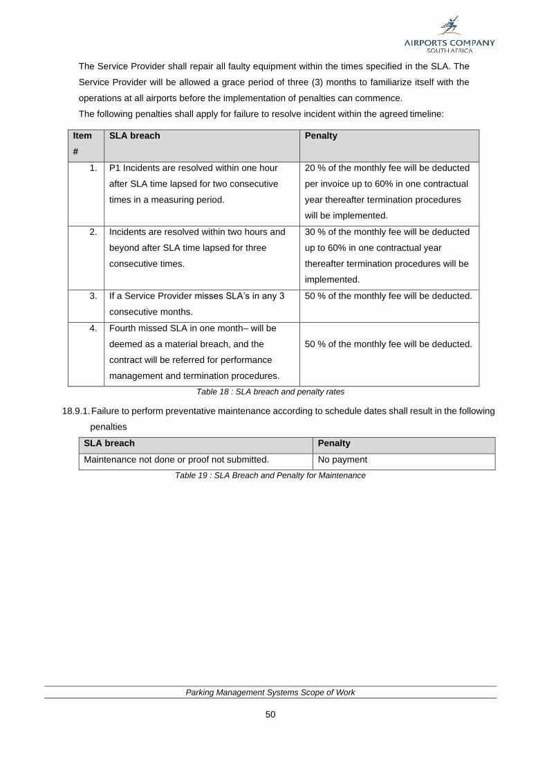
Parking Management Systems Scope of Work
50
The Service Provider shall repair all faulty equipment within the times specified in the SLA. The
Service Provider will be allowed a grace period of three (3) months to familiarize itself with the
operations at all airports before the implementation of penalties can commence.
The following penalties shall apply for failure to resolve incident within the agreed timeline:
Item
#
SLA breach Penalty
1. P1 Incidents are resolved within one hour
after SLA time lapsed for two consecutive
times in a measuring period.
20 % of the monthly fee will be deducted
per invoice up to 60% in one contractual
year thereafter termination procedures
will be implemented.
2. Incidents are resolved within two hours and
beyond after SLA time lapsed for three
consecutive times.
30 % of the monthly fee will be deducted
up to 60% in one contractual year
thereafter termination procedures will be
implemented.
3. If a Service Provider misses SLA’s in any 3
consecutive months.
50 % of the monthly fee will be deducted.
4. Fourth missed SLA in one month– will be
deemed as a material breach, and the
contract will be referred for performance
management and termination procedures.
50 % of the monthly fee will be deducted.
Table 18 : SLA breach and penalty rates
18.9.1. Failure to perform preventative maintenance according to schedule dates shall result in the following
penalties
SLA breach Penalty
Maintenance not done or proof not submitted. No payment
Table 19 : SLA Breach and Penalty for Maintenance

Parking Management Systems Scope of Work
51
19. MEETING AND REPORTING REQUIREMENTS
19.1. Meetings
19.1.1. As part of ongoing performance management, ACSA requires that the Supplier provides the reports
Articulated in table 50 and attend periodic meetings. These meetings will be held weekly (every
Wednesday), and/or on demand for the duration of the project and arranged by the ACSA Project
Management to discuss the following, but not limited to: Project progress delays, risks, issues,
financials and all other requirements related to the project.
19.1.2. The meetings must be attended by Service Provider’s Project Manager as well as ACSA Project
Manager;
19.1.3. These meetings will be held monthly (during the last week of the month). Purpose of these meetings
is to provide the Service Provider a platform to report on their performance for the current month;
and
19.1.4. If the Service Provider fails to attend any of the scheduled meetings, ACSA will withhold invoice
payment for the month.
Table 20 is an articulation of meetings schedule. The project management portion of these meetings will become
redundant once the system or solution has been commissioned and handed over to operations. Therefore, the
Project board meetings expressed in table 20 will be applicable during the execution part of the project and not
during the operational stage.
# Frequency Meeting
Name
Standing
Agenda
Participants and
Roles
Documents
to be
submitted
prior to
meeting
Documents to
be produced
after meeting
1. Monthly
(27th or
next
working
day).
SLA
meeting.
1. Consumables
Usage.
2. Calendar
month
Incidents
(System
Availability).
3. Payment.
4. Monthly
services
deliverables.
5. Discuss SLA
Report.
6. Discuss SLA
improvement
plan.
7. Discuss
penalties.
1. Service
Provider
account
manager.
2. ACSA
representatives.
3. ACSA will chair
the meeting.
Maintenance
Report.
1. Minutes of
meeting.
2. Action
items.
3. Penalties.
4. Acceptance
of
deliverables.
5. Payment
status.
6. Deliverables
for the
upcoming
month.
7. ACSA will
produce
minutes and
action items.

Parking Management Systems Scope of Work
52
2. Monthly -
As
required.
Project
Board
meeting.
1. Status.
2. Risks /
Issues.
3. Next
milestones.
4. Monthly
services
deliverables.
1. Service
Provider
account
manager.
2. ACSA
representatives.
Project
Report
1. Minutes of
meeting.
2. Action items
3. Acceptance
of
deliverable.
4. Payment
status.
5. Deliverables
for the
upcoming
month.
3. Adhoc. Adhoc. Adhoc. As and when
required.
Either party Lync (Online) or
in Person
(Physical).
Table 20 : Meetings schedule
19.2. Reporting
Table 21 is an articulation of reports schedule.
# Frequency Meeting
Name
Standing
Agenda
Participants and
Roles
Documents
to be
submitted
prior to
meeting
Documents to
be produced
after meeting
1. Monthly
(27th or
next
working
day or date
agreed
upon by
both
parties).
SLA
meeting.
1. Consumables
Usage
2. Calendar
month
Incidents
(System
Availability).
3. Payment.
4. Monthly
services
deliverables.
5. Discuss SLA
Report.
6. Discuss SLA
improvement
plan.
7. Discuss
penalties.
1. Service
Provider
account
manager.
2. ACSA
representatives.
3. ACSA will chair
the meeting.
Maintenance
Report.
1. Minutes of
meeting.
2. Action items.
3. Penalties.
4. Acceptance
of
deliverables.
5. Payment
status
6. Deliverables
for the
upcoming
month
7. ACSA will
produce
minutes and
action items.
2. Monthly -
As
required.
Project
Board
meeting
1. Status
2. Risks /
Issues.
3. Next
milestones.
1. Service
Provider
account
manager.
Project
Report.
1. Minutes of
meeting.
2. Action items.

Parking Management Systems Scope of Work
53
4. Monthly
services
deliverables.
2. ACSA
representatives.
3. Acceptance
of
deliverables.
4. Payment
status
5. Deliverables
for the
upcoming
month.
3. Adhoc. Adhoc. Adhoc. As and when
required.
Either party. Lync (Online) or
in Person
(Physical).
Table 21 : Reports schedule
19.2.1. All reports must be submitted three days prior to the meeting day. The meeting will be attended by
the Service Provider’s account manager, Technical lead, Project manager and ACSA’s IT contract
management, procurement and end users; and
19.2.2. If reports are not delivered within the stipulated times, ACSA will withhold invoice payment for the
month until the reports are submitted and reviewed.
20. DOCUMENTATION
20.1. The successful Service Provider is expected to keep detailed and updated documentation of including but
not limited to the following.
20.1.1. Technical architecture diagrams incorporating all architecture domains ie Business, Information
Systems and Technology);
20.1.2. List of all equipment installed;
20.1.3. Inventory list of spares on hold;
20.1.4. List of decommissioned or old equipment;
20.1.5. Maintenance report template and schedules;
20.1.6. Training manual;
20.1.7. System manual
20.1.8. Cable route drawings;
20.1.9. Certifications (electrical, Mechanical and civil)
20.1.10. Standard operating procedure;
20.1.11. Daily check list;
20.1.12. Equipment manuals; and
20.1.13. Any other relevant documentation
20.2. Prior to the solution going live, the relevant Operational department must ensure that an Operational
handover checklist has been duly completed and signed by all relevant stakeholders (Service Provider,
Project Team and the applicable Operations department; and
20.3. Accreditation and partnership of OEM.The successful Service Provider is expected to provide written

Parking Management Systems Scope of Work
54
proof of their partnership status with the OEM or any form of accreditation that certifies that the supplier
has the necessary resources and skills to work on the specific technologies or devices.
21. AIRPORT LAYOUTS AND SYSTEM ARCHITECTURAL MODELS
21.1. Owning to size and space, all maps for Airports layouts and current system Architectural models have
been dropped on the IT Projects repository. To access them, Click here.
21.2. Note that logical access to this folder is needed otherwise log a call with the IT Service desk. Also, note
that these maps or models were not available for some airports.
22. IMPLEMENTATION APPROACH
The two Airports in scope for phase 1 are ORTIA and KSIA.The implementation must unfold concurrently.