park-king install hardcopy - american custom lifts
TRANSCRIPT

Installation Manual
Model ACP-7 Park-King

Required Installation Tools & MaterialsTOOLS
? Wrenches (open end) 7/16”, 1/2”, 3/4”, 11/16”, 1 1/16”
? Ratchets/Sockets7/16”, 1/2”, 3/4”
? Crescent wrench? Large punch? Funnel? Tape measure? Locking pliers or vice grips? Come-along (optional)? Fork lift or Crane lift? 4ft Level ? Line chalk
MATERIALS
? Teflon tape
? Bearing or silicon grease
? Approx. 4 gallons of 10-wt, non-foaming, non-detergent hydraulic oil.
NOTEYou will need at least two people (including yourself) to properly install this lift.
Installation usually takes 4 – 6 hrs.
IMPORTANT! Be sure read this manual completely through before operating your lift.
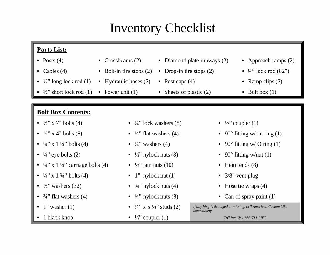
Inventory ChecklistParts List:
• Posts (4) • Crossbeams (2) • Diamond plate runways (2) • Approach ramps (2)
• Cables (4) • Bolt-in tire stops (2) • Drop-in tire stops (2) • ¼” lock rod (82”)
• ½” long lock rod (1) • Hydraulic hoses (2) • Post caps (4) • Ramp clips (2)
• ½” short lock rod (1) • Power unit (1) • Sheets of plastic (2) • Bolt box (1)
Bolt Box Contents:
• ½” x 7” bolts (4) • ¼” lock washers (8) • ½” coupler (1)
• ½” x 4” bolts (8) • ¼” flat washers (4) • 90° fitting w/out ring (1)
• ¼” x 1 ¼” bolts (4) • ¼” washers (4) • 90° fitting w/ O ring (1)
• ¼” eye bolts (2) • ½” nylock nuts (8) • 90° fitting w/nut (1)
• ¼” x 1 ¼” carriage bolts (4) • ½” jam nuts (10) • Heim ends (8)
• ¼” x 1 ¾” bolts (4) • 1” nylock nut (1) • 3/8” vent plug
• ½” washers (32) • ¾” nylock nuts (4) • Hose tie wraps (4)
• ¾” flat washers (4) • ¼” nylock nuts (8) • Can of spray paint (1)
• 1” washer (1) • ¼” x 5 ½” studs (2)
• 1 black knob • ½” coupler (1)
If anything is damaged or missing, call American Custom Lifts immediately
Toll free @ 1-888-711-LIFT

Park-King MODELS: Key Std. Narrow SUV
Total Width (to outside base plates)
A 115" 109" 115"
Width Between Posts
B 99" 93" 99"
Width Between Base Plates
C 87" 81" 87"
Width Between Tracks
D 38" 38" 38"
Ramp Length E 36" 36" 36"
Track Length (without ramp)
F 160" 160" 180"
Track Outside Width
G 76" 76" 76"
Track Width H 19" 19" 19"
Base Plate Dimensions
I 12" x 12" 12" x 12" 12" x 12"
Overall Length (to outside base plates)
J 170.75" 170.75" 190.75"
Max. Clearance(for lower vehicle)
K 67.5" on lock
67.5" on lock
77.5" on lock
Overall Height L 84" 84" 94"
Length Between Posts
M 151.5" 151.5" 171.5"
SIDE
VIEW
TOP VIEW
Specs. SheetSpecs. Sheet

(1) Remove protective covering and unbolt* runways.
*The same nuts and bolts used in crate assembly will be used to secure post caps.
(2) Remove steel band from around the lift.
(3) Lay out all parts on the ground and inventory them, using the preceding inventory list to make sure everything is there.
Step 1 Crate disassembly
procedures

Step 2 Chalk out a rectangle in working area
170 ¾” (narrow & std.)
190” (SUV)
111” (std. & SUV)
105” (narrow)
All measurements are to the outside of the base platesAll measurements are to the outside of the base plates
Cylinder ramp Offside ramp
Tire stop
(1) Make sure you position your lift so you have enough room, lengthwise, to insert the long lock rod (see step 10). Also, remember to allow enough surrounding room for power unit and to exit vehicle.
(2) Decide where you want to install the power unit (left front or right rear). We suggest mounting the power unit on the left front post to avoid possible interference with the manual lock release lever when you drive your car on and off the lift.
Insert long lock rod here
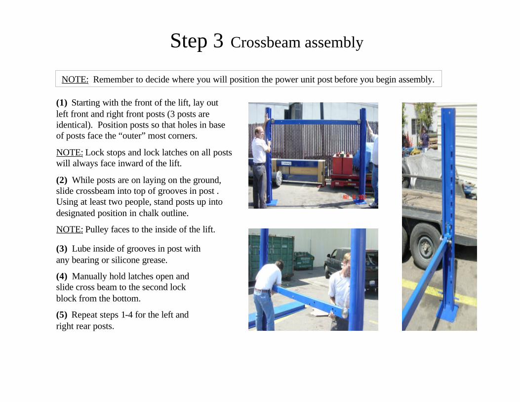
Step 3 Crossbeam assembly
(1) Starting with the front of the lift, lay out left front and right front posts (3 posts are identical). Position posts so that holes in base of posts face the “outer” most corners.
NOTE: Lock stops and lock latches on all posts will always face inward of the lift.
(2) While posts are on laying on the ground, slide crossbeam into top of grooves in post . Using at least two people, stand posts up into designated position in chalk outline.
NOTE: Pulley faces to the inside of the lift.
(3) Lube inside of grooves in post with any bearing or silicone grease.
(4) Manually hold latches open and slide cross beam to the second lock block from the bottom.
(5) Repeat steps 1-4 for the left and right rear posts.
NOTE: Remember to decide where you will position the power unit post before you begin assembly.

Step 4 Installing offside runway
(1) Determine where offside (w/out cylinder) runway will go. Always, opposite side of power unit
(2) Measure distance between inside of crossbeam (156”).
(3) Set offside runway in place.
(4) Bolt offside runway in place (as seen above) using ½” x 4” bolts, ½” nuts and washers.
NOTE: Assuming that you are mounting the power unit on the left front, the ramp clips (hold ramps and drop-in tire stops) should be installed on end furthest from the power unit mount.
Ramp clip
Power unit mount

Steps 5 & 6 Installing cylinder runway & post caps
Warning: Runway with cylinder weighs almost 400 lbs. We highly recommend using a forklift or boom at this stage of the installation. Improperly lifting this equipment can cause serious injury.
(1) Place cylinder ramp into place. Make sure hydraulic line outlet is closest to the motor mount.
(2) Bolt runway in place using ½” x 4” bolts, ½” nuts and washers. Remember that bolt-in tire stops are normally installed on end closest to the motor mount.
Locate post caps (4), bolts (12) and washers (24) and secure post caps (as seen above).
NOTE: When securing middle bolt, it is recommended to use a shallow extension socket to avoid dropping washer and bolt into inside of post.

Step 7 cylinder extension
Extend the cylinder: First, remove the protective netting from end of cylinder. Second, attach the cable holder (thick metal) and cable retainer (thin metal) with 1” washer and nut to the end of the cylinder. Third,remove both plastic plugs from the cylinder. Fourth, with two people, grab the cable block and pull until the cylinder is extended.
*The fourth step can also be done with a come-along tool (as shown above).
cable holder
cable retainer

Step 8 Cable installation
Use nut for leveling each corner
left rear(LR)
right front (RF)
right rear (RR)
left front (LF)
rear cables to lower pulleys
left front post
(1) Thread the cables per drawing. Starting at the top of the post makes this easier. You can route the thinner end of the cable through the pulleys without removing them.
(2) Connect the cables up to the posts using the ¾” nuts and washers. Tighten the nut on the top of the post only until it breaks through the nylon, then stop. Final adjustment will be done later.
powerunit
Cable length
(LR) - shortest
(RR) – 2nd shortest
(LF) – 2nd longest
(RF) - longest

Step 9 Installing the power unit & hydraulic lines
Power Unit: As seen above, install power unit using ¼” bolts (4), ¼” lock washers (4) and ¼” nuts (8).
Hydraulic Lines: Connect hydraulic valve fittings to the power unit and cylinder. Connect hoses as shown above. NOTE: Be careful not to force or cross thread fittings.
Step 10 lock linkage assembly (part 1)
Eye bolt: Install a ¼” nut and washer on the eyebolt, slide the eyebolt into crossbeam. Add ¼” washer and nut on other side and tighten. Be sure eye is facing to outside of lift.
Lock rods: Place a 1 ½” copper spacer on short rod (bent handle) insert into 5/8” hole in cross beam (power unit end) and through the holder on underside of track. Place a copper spacer on long rod (“T” weld) and insert on opposite end of track. See next page
long rod
long rod
short rod

Step 10 lock linkage assembly (Part 2)
(1) Place a ½” nut and lock washer on the ends of each rod. Next, with the ½” coupler connect the two lock rods together. (Do not tighten nuts until step 6)
(2) Find the short ¼” lock linkage rod in bolt box and thread a heimend on both ends. Place a ¼” x 1 ¼” bolt through the heim end then through the ¼” lock washer and attach to the bottom of the “T” (handle end). Secure with nylock nut. Lever handle @ 1 o’clock position.
(3) Connect the other heim end to the latch on the cross beam. Insert a ¼” x 1 ½” bolt then the ¼” lock washer, through the latch, secure with ¼” nylock nut. (Do not over-tighten). This should be snug, but should also allow the heim to swivel.
(4) Install the long ¼” linkage rod rod through the eyebolt and connect it to the “T” handle and the other end to the latch.
(5) Align the “T” on the long lock rod to match the “T” on the short lock rod. Connect the linkage on the other end of the lift at this time.
(6) Now tighten the jam nuts and coupler under the track in lock rod assembly.
long rod
short rod
1 ½” spacer
short rod long rodcoupler
tightening nuts
lock washer
heim end

Final Assembly1. Go back over all bolts and make sure everything is tight!
2. Fill power unit with 10-weight, non-foaming, non-detergent hydraulic oil (approx. 4 gallons).
3. Connect power unit to electric lock release solenoid then plug in power unit.
4. Check cylinder and hoses for leaks and double-check that the cables are positioned correctly inside the pulleygrooves (at all four corners and under ramp).
1. Note: Raise and lower lift about two feet with nothing on it to bleed the system. With no weight and with new paint inside the columns, the lift may stick at first coming down, so be patient and run it up and down at least 5-10 times.
2. To raise lift: Insert key into power unit and turn clockwise. Note: Watch all pulleys to make sure that cables stay in pulley grooves. Keep key turned clockwise until lift raises 1 or 2 inches above desired locking position. Once lift is at desired height, simply turn key counterclockwise to the off position and push down slowly on the valve lever with black knob (located on power unit) until lift rests on lock stops on all four posts. Note: Make sure all lock four locks are resting on lock stops at the same locking positions for all four posts.
3. To lower lift: Turn safety key control switch clockwise to raise lift off locks. Raise platform approximately 1or 2 inches until locks can be disengaged. Disengage locks by either pushing on electric lock release button located on power unit or pulling down on black-knobbed manual lock release lever located on crossrail of lift next to power unit. Then lower lift by pushing down on black-knobbed valve lever while continuing to hold down electric lock release button/manual lock release lever.
4. Level the lift: Raise lift slightly so that each lock is at least ½” above its lock block. Now adjust each corner by tightening or loosening cable nut on top of each post until all locks are sitting the same distance above lock blocks.
5. Lower lift completely after leveling it, and install drip pans and approach ramps.
6. Slowly drive vehicle onto lift. Ensure vehicle is left in park (automatic) or in gear (manual) with parking brake on.
7. Raise the lift: Turn control key on power unit clockwise. Safety locks will automatically engage as you raise the lift, making a clanking sound. Note: Once you have achieved desired height, lower lift by depressing valve lever on power unit until locks rest on lock blocks. Do not leave lift on the hydraulics. This creates a safety hazard and may damage the power unit.
Operating Instructions

SAFETY TIPSPOST THESE TIPS WHERE THEY WILL BE A CONSTANT REMINDER TO YOUR LIFT OPERATOR.
•Inspect your lift on a regular basis. Never operate lift if it malfunctions or if it has broken or damaged parts. Repairs should be made with original manufacturer’s parts.
•Positive locks are designed to engage automatically when lift is raised. Do not block them open or override them.
•Never overload your lift. Manufacturer’s rated capacity for this lift is 7000 lbs.
•Never raise vehicle with anyone inside it. Do not allow bystanders (especially children) in lift area during operation.
•Always keep lift area free of obstructions, grease, oil, trash and other debris.
•Never roll vehicle back and forth on lift.
•Never raise only part of a vehicle i.e. front or rear only. Lift the entire vehicle. All tires must be on the lift while it isbeing raised or lowered.
•When jacking up vehicle off the lift, use a stand to support the vehicle.
•Never climb on lift to access vehicle.
•If you are working under vehicle, lift should be raised high enough for locking device to be engaged.
Lift Maintenance•Check all bolts and hydraulic connections within two weeks of initial assembly. Thereafter, check bolts and connections on a regular basis.
•Every few months, spray the bronze bushings in the center of the pulleys with silicone spray.
•Keep post grooves lubricated with lightweight grease or lubricant.

Caster Kit (optional)
OPTION 11. Slide caster arms under “T” on posts.
2. Take out caster pins and lower lift onto mounting bracket (lining up holes of bracket and crossbeam).
3. Insert caster pins and lower lift until all posts are off the ground.
4. Reverse process to remove.
OPTION 21. Raise lift 3-4 ft from floor.
2. Using caster pins, attach mounting bracket to inside to inside of ramp on cross beam.
3. Lower lift and make sure caster arms slide under “T” on posts.
4. Lower lift until all posts are off the ground.
5. Reverse process to remove.
NOTE: This method may scratch base plates when caster is lowered to the ground.
“T” mounting bracket
caster arms
caster pin